WO2018043179A1 - 放熱板及びその製造方法 - Google Patents
放熱板及びその製造方法 Download PDFInfo
- Publication number
- WO2018043179A1 WO2018043179A1 PCT/JP2017/029787 JP2017029787W WO2018043179A1 WO 2018043179 A1 WO2018043179 A1 WO 2018043179A1 JP 2017029787 W JP2017029787 W JP 2017029787W WO 2018043179 A1 WO2018043179 A1 WO 2018043179A1
- Authority
- WO
- WIPO (PCT)
- Prior art keywords
- rolling
- heat sink
- composite
- manufacturing
- layer
- Prior art date
- Legal status (The legal status is an assumption and is not a legal conclusion. Google has not performed a legal analysis and makes no representation as to the accuracy of the status listed.)
- Ceased
Links
Images


Classifications
-
- B—PERFORMING OPERATIONS; TRANSPORTING
- B22—CASTING; POWDER METALLURGY
- B22F—WORKING METALLIC POWDER; MANUFACTURE OF ARTICLES FROM METALLIC POWDER; MAKING METALLIC POWDER; APPARATUS OR DEVICES SPECIALLY ADAPTED FOR METALLIC POWDER
- B22F7/00—Manufacture of composite layers, workpieces, or articles, comprising metallic powder, by sintering the powder, with or without compacting wherein at least one part is obtained by sintering or compression
- B22F7/06—Manufacture of composite layers, workpieces, or articles, comprising metallic powder, by sintering the powder, with or without compacting wherein at least one part is obtained by sintering or compression of composite workpieces or articles from parts, e.g. to form tipped tools
- B22F7/08—Manufacture of composite layers, workpieces, or articles, comprising metallic powder, by sintering the powder, with or without compacting wherein at least one part is obtained by sintering or compression of composite workpieces or articles from parts, e.g. to form tipped tools with one or more parts not made from powder
-
- B—PERFORMING OPERATIONS; TRANSPORTING
- B22—CASTING; POWDER METALLURGY
- B22F—WORKING METALLIC POWDER; MANUFACTURE OF ARTICLES FROM METALLIC POWDER; MAKING METALLIC POWDER; APPARATUS OR DEVICES SPECIALLY ADAPTED FOR METALLIC POWDER
- B22F3/00—Manufacture of workpieces or articles from metallic powder characterised by the manner of compacting or sintering; Apparatus specially adapted therefor ; Presses and furnaces
- B22F3/10—Sintering only
- B22F3/1003—Use of special medium during sintering, e.g. sintering aid
- B22F3/1007—Atmosphere
-
- B—PERFORMING OPERATIONS; TRANSPORTING
- B22—CASTING; POWDER METALLURGY
- B22F—WORKING METALLIC POWDER; MANUFACTURE OF ARTICLES FROM METALLIC POWDER; MAKING METALLIC POWDER; APPARATUS OR DEVICES SPECIALLY ADAPTED FOR METALLIC POWDER
- B22F7/00—Manufacture of composite layers, workpieces, or articles, comprising metallic powder, by sintering the powder, with or without compacting wherein at least one part is obtained by sintering or compression
- B22F7/06—Manufacture of composite layers, workpieces, or articles, comprising metallic powder, by sintering the powder, with or without compacting wherein at least one part is obtained by sintering or compression of composite workpieces or articles from parts, e.g. to form tipped tools
- B22F7/062—Manufacture of composite layers, workpieces, or articles, comprising metallic powder, by sintering the powder, with or without compacting wherein at least one part is obtained by sintering or compression of composite workpieces or articles from parts, e.g. to form tipped tools involving the connection or repairing of preformed parts
-
- B—PERFORMING OPERATIONS; TRANSPORTING
- B23—MACHINE TOOLS; METAL-WORKING NOT OTHERWISE PROVIDED FOR
- B23P—METAL-WORKING NOT OTHERWISE PROVIDED FOR; COMBINED OPERATIONS; UNIVERSAL MACHINE TOOLS
- B23P15/00—Making specific metal objects by operations not covered by a single other subclass or a group in this subclass
- B23P15/26—Making specific metal objects by operations not covered by a single other subclass or a group in this subclass heat exchangers or the like
-
- B—PERFORMING OPERATIONS; TRANSPORTING
- B32—LAYERED PRODUCTS
- B32B—LAYERED PRODUCTS, i.e. PRODUCTS BUILT-UP OF STRATA OF FLAT OR NON-FLAT, e.g. CELLULAR OR HONEYCOMB, FORM
- B32B15/00—Layered products comprising a layer of metal
- B32B15/01—Layered products comprising a layer of metal all layers being exclusively metallic
-
- B—PERFORMING OPERATIONS; TRANSPORTING
- B32—LAYERED PRODUCTS
- B32B—LAYERED PRODUCTS, i.e. PRODUCTS BUILT-UP OF STRATA OF FLAT OR NON-FLAT, e.g. CELLULAR OR HONEYCOMB, FORM
- B32B15/00—Layered products comprising a layer of metal
- B32B15/20—Layered products comprising a layer of metal comprising aluminium or copper
-
- C—CHEMISTRY; METALLURGY
- C22—METALLURGY; FERROUS OR NON-FERROUS ALLOYS; TREATMENT OF ALLOYS OR NON-FERROUS METALS
- C22C—ALLOYS
- C22C1/00—Making non-ferrous alloys
- C22C1/04—Making non-ferrous alloys by powder metallurgy
- C22C1/045—Alloys based on refractory metals
-
- C—CHEMISTRY; METALLURGY
- C22—METALLURGY; FERROUS OR NON-FERROUS ALLOYS; TREATMENT OF ALLOYS OR NON-FERROUS METALS
- C22C—ALLOYS
- C22C27/00—Alloys based on rhenium or a refractory metal not mentioned in groups C22C14/00 or C22C16/00
- C22C27/04—Alloys based on tungsten or molybdenum
-
- C—CHEMISTRY; METALLURGY
- C22—METALLURGY; FERROUS OR NON-FERROUS ALLOYS; TREATMENT OF ALLOYS OR NON-FERROUS METALS
- C22F—CHANGING THE PHYSICAL STRUCTURE OF NON-FERROUS METALS AND NON-FERROUS ALLOYS
- C22F1/00—Changing the physical structure of non-ferrous metals or alloys by heat treatment or by hot or cold working
- C22F1/04—Changing the physical structure of non-ferrous metals or alloys by heat treatment or by hot or cold working of aluminium or alloys based thereon
- C22F1/057—Changing the physical structure of non-ferrous metals or alloys by heat treatment or by hot or cold working of aluminium or alloys based thereon of alloys with copper as the next major constituent
-
- C—CHEMISTRY; METALLURGY
- C22—METALLURGY; FERROUS OR NON-FERROUS ALLOYS; TREATMENT OF ALLOYS OR NON-FERROUS METALS
- C22F—CHANGING THE PHYSICAL STRUCTURE OF NON-FERROUS METALS AND NON-FERROUS ALLOYS
- C22F1/00—Changing the physical structure of non-ferrous metals or alloys by heat treatment or by hot or cold working
- C22F1/16—Changing the physical structure of non-ferrous metals or alloys by heat treatment or by hot or cold working of other metals or alloys based thereon
- C22F1/18—High-melting or refractory metals or alloys based thereon
-
- F—MECHANICAL ENGINEERING; LIGHTING; HEATING; WEAPONS; BLASTING
- F28—HEAT EXCHANGE IN GENERAL
- F28F—DETAILS OF HEAT-EXCHANGE AND HEAT-TRANSFER APPARATUS, OF GENERAL APPLICATION
- F28F21/00—Constructions of heat-exchange apparatus characterised by the selection of particular materials
- F28F21/08—Constructions of heat-exchange apparatus characterised by the selection of particular materials of metal
- F28F21/081—Heat exchange elements made from metals or metal alloys
- F28F21/085—Heat exchange elements made from metals or metal alloys from copper or copper alloys
-
- H—ELECTRICITY
- H10—SEMICONDUCTOR DEVICES; ELECTRIC SOLID-STATE DEVICES NOT OTHERWISE PROVIDED FOR
- H10W—GENERIC PACKAGES, INTERCONNECTIONS, CONNECTORS OR OTHER CONSTRUCTIONAL DETAILS OF DEVICES COVERED BY CLASS H10
- H10W40/00—Arrangements for thermal protection or thermal control
- H10W40/20—Arrangements for cooling
- H10W40/25—Arrangements for cooling characterised by their materials
- H10W40/255—Arrangements for cooling characterised by their materials having a laminate or multilayered structure, e.g. direct bond copper [DBC] ceramic substrates
-
- H—ELECTRICITY
- H10—SEMICONDUCTOR DEVICES; ELECTRIC SOLID-STATE DEVICES NOT OTHERWISE PROVIDED FOR
- H10W—GENERIC PACKAGES, INTERCONNECTIONS, CONNECTORS OR OTHER CONSTRUCTIONAL DETAILS OF DEVICES COVERED BY CLASS H10
- H10W40/00—Arrangements for thermal protection or thermal control
- H10W40/20—Arrangements for cooling
- H10W40/25—Arrangements for cooling characterised by their materials
- H10W40/258—Metallic materials
-
- B—PERFORMING OPERATIONS; TRANSPORTING
- B22—CASTING; POWDER METALLURGY
- B22F—WORKING METALLIC POWDER; MANUFACTURE OF ARTICLES FROM METALLIC POWDER; MAKING METALLIC POWDER; APPARATUS OR DEVICES SPECIALLY ADAPTED FOR METALLIC POWDER
- B22F7/00—Manufacture of composite layers, workpieces, or articles, comprising metallic powder, by sintering the powder, with or without compacting wherein at least one part is obtained by sintering or compression
- B22F7/06—Manufacture of composite layers, workpieces, or articles, comprising metallic powder, by sintering the powder, with or without compacting wherein at least one part is obtained by sintering or compression of composite workpieces or articles from parts, e.g. to form tipped tools
- B22F7/062—Manufacture of composite layers, workpieces, or articles, comprising metallic powder, by sintering the powder, with or without compacting wherein at least one part is obtained by sintering or compression of composite workpieces or articles from parts, e.g. to form tipped tools involving the connection or repairing of preformed parts
- B22F2007/066—Manufacture of composite layers, workpieces, or articles, comprising metallic powder, by sintering the powder, with or without compacting wherein at least one part is obtained by sintering or compression of composite workpieces or articles from parts, e.g. to form tipped tools involving the connection or repairing of preformed parts using impregnation
-
- B—PERFORMING OPERATIONS; TRANSPORTING
- B22—CASTING; POWDER METALLURGY
- B22F—WORKING METALLIC POWDER; MANUFACTURE OF ARTICLES FROM METALLIC POWDER; MAKING METALLIC POWDER; APPARATUS OR DEVICES SPECIALLY ADAPTED FOR METALLIC POWDER
- B22F2301/00—Metallic composition of the powder or its coating
- B22F2301/10—Copper
-
- B—PERFORMING OPERATIONS; TRANSPORTING
- B22—CASTING; POWDER METALLURGY
- B22F—WORKING METALLIC POWDER; MANUFACTURE OF ARTICLES FROM METALLIC POWDER; MAKING METALLIC POWDER; APPARATUS OR DEVICES SPECIALLY ADAPTED FOR METALLIC POWDER
- B22F2998/00—Supplementary information concerning processes or compositions relating to powder metallurgy
- B22F2998/10—Processes characterised by the sequence of their steps
-
- B—PERFORMING OPERATIONS; TRANSPORTING
- B22—CASTING; POWDER METALLURGY
- B22F—WORKING METALLIC POWDER; MANUFACTURE OF ARTICLES FROM METALLIC POWDER; MAKING METALLIC POWDER; APPARATUS OR DEVICES SPECIALLY ADAPTED FOR METALLIC POWDER
- B22F2999/00—Aspects linked to processes or compositions used in powder metallurgy
-
- B—PERFORMING OPERATIONS; TRANSPORTING
- B23—MACHINE TOOLS; METAL-WORKING NOT OTHERWISE PROVIDED FOR
- B23P—METAL-WORKING NOT OTHERWISE PROVIDED FOR; COMBINED OPERATIONS; UNIVERSAL MACHINE TOOLS
- B23P2700/00—Indexing scheme relating to the articles being treated, e.g. manufactured, repaired, assembled, connected or other operations covered in the subgroups
- B23P2700/10—Heat sinks
-
- C—CHEMISTRY; METALLURGY
- C22—METALLURGY; FERROUS OR NON-FERROUS ALLOYS; TREATMENT OF ALLOYS OR NON-FERROUS METALS
- C22F—CHANGING THE PHYSICAL STRUCTURE OF NON-FERROUS METALS AND NON-FERROUS ALLOYS
- C22F1/00—Changing the physical structure of non-ferrous metals or alloys by heat treatment or by hot or cold working
Definitions
- the present invention relates to a heat radiating plate used for efficiently dissipating heat generated from a heating element such as a semiconductor element, and a manufacturing method thereof.
- heat sink In order to efficiently dissipate the heat generated from the semiconductor element from the semiconductor device, a heat sink (heat sink) is used.
- This heat sink is required to have high thermal conductivity in terms of its function, and since it is joined to a semiconductor, ceramic circuit board, metal package member, etc. by soldering or brazing, it has a thermal expansion coefficient close to that of the member to be joined (low heat Expansion coefficient).
- a Mo—Cu composite material has been used as a heat radiating plate having a high thermal conductivity and a low thermal expansion coefficient (for example, Patent Document 1).
- the Mo—Cu composite material used for the heat sink is formed by pressing a Mo powder or a mixed powder of Mo powder and Cu powder into a green compact, and this green compact is subjected to reduction sintering as necessary. Thereafter, Cu infiltration or densification treatment is performed to obtain a Mo—Cu composite material, and the Mo—Cu composite material is rolled. Since Mo is hardly dissolved in Cu, this Mo-Cu composite material has a two-phase structure of Mo and Cu, and a heat sink utilizing the characteristics of Mo having a low thermal expansion coefficient and Cu having a high thermal conductivity.
- Patent Document 2 discloses a heat sink based on the Mo—Cu composite material as described above, in which a Cu plate is pressure-bonded to both sides of a Mo—Cu composite material obtained through a specific rolling process.
- the heat radiating plate has a higher thermal conductivity than the [Cu / Mo / Cu] clad material and is excellent in press punchability.
- Patent Document 1 discloses a manufacturing method in which warm rolling is performed by primary rolling and cold rolling is performed by secondary rolling. However, even in this manufacturing method, Mo particles are hardly deformed. On the premise, warm rolling (primary rolling) is an essential process.
- heat dissipation of a heat sink has become more important due to higher output of semiconductors.
- heat dissipation in the thickness direction is more important than heat dissipation in the plate surface direction.
- an object of the present invention is to provide a heat dissipation plate having a low thermal expansion coefficient and a high thermal conductivity having a clad structure of a Mo—Cu composite material and a Cu material.
- Another object of the present invention is to provide a manufacturing method capable of stably and inexpensively manufacturing a heat sink having such excellent heat characteristics.
- the cladding structure of the heat dissipation plate described in Patent Document 2 is a Cu / (Cu—Mo) / Cu structure, but according to the study of the present inventors, (Cu—Mo) / Cu / (Cu—Mo). ) It was found that a higher thermal conductivity can be obtained by using the structure while having a similar low thermal expansion coefficient. Specifically, in the (Cu—Mo) / Cu / (Cu—Mo) structure, the heat conduction in the plate thickness direction is the same as that of the Cu / (Cu—Mo) / Cu structure even though the reduction ratio is the same at the same Cu ratio. It was found that the rate increased by 10 W / m ⁇ K or more, and further increased depending on the conditions.
- the clad material having such a (Cu—Mo) / Cu / (Cu—Mo) structure is manufactured, the material is cold-rolled at a high pressure reduction rate (total reduction rate), so that the thermal expansion coefficient is reduced. It turns out that it falls more effectively.
- a (Cu—Mo) / Cu / (Cu—Mo) clad material particularly by optimizing the Cu content of the Cu—Mo composite layer, high thermal conductivity and low thermal expansion coefficient can be achieved. It turned out to be highly satisfying.
- the present invention has been made on the basis of the above-described findings and has the following gist.
- a radiator plate in which a Cu—Mo composite layer, a Cu layer, and a Cu—Mo composite layer are laminated in this order in the thickness direction of the plate, The heat dissipation plate, wherein the Cu—Mo composite layer has a plate thickness cross-sectional structure in which a flat Mo phase is dispersed in a Cu matrix.
- Cu—Mo composite layers and Cu layers are alternately laminated to form three or more Cu—Mo composite layers and two or more Cu layers.
- An outer layer is a heat sink made of a Cu-Mo composite layer, The heat dissipation plate, wherein the Cu—Mo composite layer has a plate thickness cross-sectional structure in which a flat Mo phase is dispersed in a Cu matrix.
- the thermal conductivity in the thickness direction is 200 W / m ⁇ K or more, and the in-plane average thermal expansion coefficient from 50 ° C. to 800 ° C. is 10 A heat radiating plate characterized by being 0.0 ppm / K or less.
- the thermal conductivity in the thickness direction is 250 W / m ⁇ K or more, and the average in-plane thermal expansion coefficient from 50 ° C. to 800 ° C.
- the heat conductivity in the thickness direction is provided on one or both sides of the heat sink main body composed of the laminated Cu—Mo composite layer and the Cu layer.
- a method of manufacturing a heat sink comprising obtaining a heat sink in which a Cu—Mo composite layer made of Cu—Mo composite (a) and a Cu layer made of Cu material (b) are laminated.
- the Cu—Mo composite material (a) is a step of pressing a mixed powder of Mo powder and Cu powder into a green compact, and reducing the green compact
- a heat-radiating plate manufacturing method characterized by being obtained through a step of sintering in a neutral atmosphere or vacuum to form a sintered body.
- the Cu—Mo composite material (a) is formed by pressing a mixed powder of Mo powder and Cu powder into a green compact, and reducing the green compact.
- a heat-radiating plate manufacturing method characterized by being obtained through a step of sintering in a neutral atmosphere or vacuum to form a sintered body and a step of densifying the sintered body.
- the Cu—Mo composite material (a) is formed by pressing a Mo powder or a mixed powder of Mo powder and Cu powder into a green compact; It was obtained through a step of sintering the body in a reducing atmosphere or vacuum to obtain a sintered body, and a step of impregnating the sintered body with Cu melted in a non-oxidizing atmosphere or vacuum.
- a manufacturing method of a heat sink characterized by being.
- the Cu—Mo composite material (a) is a step of pressing a mixed powder of Mo powder and Cu powder into a green compact, and reducing the green compact A step of sintering in a neutral atmosphere or vacuum to form a sintered body, a step of densifying the sintered body, and a step of rolling (y) the densified Cu-Mo composite material A method of manufacturing a heat sink, characterized by being obtained through the process.
- the Cu—Mo composite material (a) is a step of pressing a Mo powder or a mixed powder of Mo powder and Cu powder into a green compact; A step of sintering the body in a reducing atmosphere or vacuum to form a sintered body, a step of impregnating the sintered body with Cu melted in a non-oxidizing atmosphere or vacuum, and impregnating the Cu A method of manufacturing a heat sink, characterized by being obtained through a step of rolling (y) the Cu—Mo composite material. [17] In the manufacturing method of [15] or [16], the total rolling reduction of the Cu—Mo composite (a) obtained by combining the cold rolling (x) and the rolling (y) is 70 to 99%.
- the manufacturing method of a heat sink characterized by performing the following (1) or / and (2) warm rolling. (1) Perform warm rolling instead of cold rolling (x). (2) Rolling (y) is performed by warm rolling.
- the heat sink of the present invention has excellent thermal characteristics such as low thermal expansion coefficient and high thermal conductivity. Moreover, according to the manufacturing method of this invention, the heat sink which has such the outstanding thermal characteristic can be manufactured stably and at low cost.
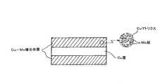
- Explanatory drawing which shows typically the board thickness cross section of the heat sink of this invention which has a three-layer clad structure
- Explanatory drawing which shows typically the plate
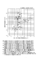
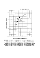
- the graph which shows the thermal characteristic (The thermal conductivity of a plate
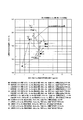
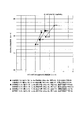
- the graph which shows the thermal characteristic (The thermal conductivity of a plate
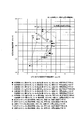
- the graph which shows the heat characteristic (heat conductivity of a plate
- the one having a three-layer clad structure is a heat sink in which a Cu—Mo composite layer, a Cu layer, and a Cu—Mo composite layer are laminated in this order in the thickness direction.
- the composite layer has a plate thickness cross-sectional structure in which a flat Mo phase is dispersed in a Cu matrix.
- FIG. 1 schematically shows a thickness cross section of the heat sink of the present invention having this three-layer cladding structure.
- the Cu—Mo composite layer and the Cu layer of the heat dissipation plate of the present invention are formed by diffusion bonding the laminated Cu—Mo composite material and the Cu material, and have a diffusion bonding portion between both layers.
- the heat dissipation plate of the present invention may have a clad structure of five or more layers.
- the clad structure has a Cu—Mo composite layer and a Cu layer that are alternately laminated in the plate thickness direction to form three or more layers of Cu—
- the heat sink is composed of a Mo composite layer and two or more Cu layers, and the outermost layer on both sides is a Cu-Mo composite layer, and the Cu-Mo composite layer is flat in a Cu matrix. It has a plate thickness cross-sectional structure in which the Mo phase is dispersed.
- FIG. 2 schematically shows a thickness cross section of the heat sink of the present invention having a five-layer cladding structure.
- a heat sink of the present invention for example, a heat sink of a (Cu—Mo) / Cu / (Cu—Mo) structure) in which the outermost layers on both sides are composed of a Cu—Mo composite layer as described above is disclosed in Patent Document 2. Although it has a higher thermal conductivity than a heat sink with a Cu / (Cu—Mo) / Cu structure, it is considered that this is due to the following difference in action and effect. In other words, in the case of the Cu / (Cu—Mo) / Cu structure disclosed in Patent Document 2, the thermal conductivity is between the outer layer (Cu layer)> the inner layer (Cu—Mo composite layer), and therefore, between the outer layer and the inner layer.
- the heat resistance at the interface is high, and the heat that enters the outer layer (Cu layer) is reflected and scattered at the interface between the outer layer and inner layer, disturbing the heat flow, so the heat does not transfer well to the inner layer (Cu-Mo composite layer) side. Therefore, the thermal conductivity in the plate thickness direction is considered to be lowered.
- the thermal conductivity is the outer layer (Cu—Mo composite layer) ⁇ the inner layer (Cu layer). ⁇ There is almost no thermal resistance at the interface between the inner layers, and heat entering the outer layer (Cu-Mo composite layer) is directly transferred to the inner layer (Cu layer) side, so that high thermal conductivity in the thickness direction can be obtained. it is conceivable that.
- the number of laminated layers in the cladding structure is not particularly limited, and the larger the number of laminated layers, the lower the coefficient of thermal expansion and the better the press workability, which is advantageous for press work.
- the upper limit is about 11 layers in the total number of stacked layers.
- the Cu content of the Cu—Mo composite layer is not particularly limited, but is generally about 10 to 50% by mass. As will be described later, when a relatively high Cu content (for example, 40% by mass or more) is cold-rolled at a high pressure rate, the cold rolling property is improved, and by cold rolling at a high pressure rate. It is easy to obtain an effect of decreasing the thermal expansion coefficient.
- the Cu content is preferably about 30 to 45% by mass mainly from the viewpoint of workability such as cold rollability.
- the Cu content of the Cu—Mo composite layer is preferably about 15 to 30% by mass, which is excellent in satisfying high thermal conductivity and low thermal expansion coefficient. It was found that thermal characteristics were obtained.
- the Cu content of the Cu—Mo composite layer is preferably about 15 to 30% by mass.
- the Cu content of the Cu—Mo composite layer (Cu—Mo composite material) is less than 20% by mass, there is a possibility of causing problems in cold rollability.
- the Cu content of the Cu—Mo composite layer is more preferably about 20 to 30% by mass.
- FIG. 3 and 4 show the thermal characteristics of a part of the heat radiating plates of the examples to be described later, and FIG. 3 shows the thermal conductivity in the thickness direction (thermal conductivity at room temperature). ) And the average thermal expansion coefficient in the plate surface from 50 ° C. to 800 ° C., FIG. 4 shows the thermal conductivity in the thickness direction (thermal conductivity at room temperature) and the average thermal expansion in the plate surface from 50 ° C. to 400 ° C. Each rate is shown.
- the coefficient of thermal expansion in the plate surface was measured by a push rod type displacement detection method, and the difference in elongation between 50 ° C.-800 ° C. and 50 ° C.-400 ° C. was divided by the temperature difference to obtain 50 ° C.
- the average in-plane coefficient of thermal expansion from 1 to 800 ° C. and the average in-plane coefficient of thermal expansion from 50 ° C. to 400 ° C. were determined. Further, the thermal conductivity in the plate thickness direction (thermal conductivity at room temperature) was measured by a flash method. The method for measuring and calculating the thermal characteristics is the same for the thermal characteristics shown in FIGS.
- FIG. 3 and 4 show a heat sink made of a single Cu—Mo composite material (comparative example), and a heat sink made of a three-layer clad material of Cu / (Cu—Mo) / Cu structure of Patent Document 2 (comparative example).
- the thermal characteristics of the heat radiating plate (invention example) made of the three-layer to seven-layer clad material of the present invention are shown.
- what is surrounded by a circle and connected by an arrow is a heat sink having substantially the same density. According to this, when comparing the thermal characteristics of heat sinks having substantially the same density, the heat sink of Cu / (Cu—Mo) / Cu structure in Patent Document 2 is used as a heat sink of a single Cu—Mo composite material.
- the heat dissipation plate of the present invention has substantially the same in-plane thermal expansion coefficient as the thermal characteristics of the heat dissipation plate of this Cu / (Cu—Mo) / Cu structure, but the thermal conductivity in the plate thickness direction. Is significantly higher (in this example, about 50 to 70 W / m ⁇ K higher).
- FIG. 5 and 6 show the influence of the Cu content of the Cu—Mo composite layer on the thermal characteristics of the heat sink of the present invention. This is a summary of the thermal characteristics of a part of the cladding material.
- FIG. 5 shows the thermal conductivity in the thickness direction (thermal conductivity at room temperature) and the average thermal expansion coefficient in the plate surface from 50 ° C. to 800 ° C.
- FIG. 6 shows the thermal conductivity in the thickness direction (heat at room temperature). Conductivity) and the in-plane average thermal expansion coefficient from 50 ° C. to 400 ° C., respectively.
- FIG. 5 and 6 also show the thermal characteristics of a heat sink (comparative example) made of a single Cu-Mo composite in which the Cu content of the Cu-Mo composite is almost the same as that of the heat sink of the present invention.
- the solid arrows connected to each other indicate that the Cu-Mo composite has almost the same Cu content as "a heat sink made of a single Cu-Mo composite” and "a heat sink of the present invention". It is.
- the thermal conductivity in the plate thickness direction is high, and the average thermal expansion coefficient in the plate surface is low.
- the Cu content of the Cu—Mo composite layer (Cu—Mo composite material) is less than 20 mass%, the cold rollability deteriorates, so the Cu content of the Cu—Mo composite layer is 15 mass. % Is produced by warm rolling.
- the heat conductivity in the thickness direction of the heat sink of the example of the present invention is considerably higher than that of the heat sink (comparative example) made of a single Cu—Mo composite in which the Cu content of the Cu—Mo composite is almost equal. Although it is high, the degree is particularly remarkable when the Cu content of the Cu—Mo composite is relatively low (15 mass%, 25 mass%). From the results of FIG. 5 and FIG. 6, particularly excellent thermal properties are obtained when the Cu content of the Cu—Mo composite layer is 15 to 30% by mass (and further 20 to 30% by mass considering cold rolling properties). Is considered to be obtained.
- the thicknesses of the Cu-Mo composite layer and the Cu layer, the layer thickness ratio of the Cu-Mo composite layer and the Cu layer, and the thickness of the heat sink are not particularly limited, but 5 layers or more (especially 7 layers or more)
- the thicknesses of the plurality of Cu layers are the same in order to increase the binding force of the Cu layer by the Cu—Mo composite layer.
- the thickness direction centering on the Cu-Mo composite layer at the center in the thickness direction so as to ensure thermal characteristics and prevent warping and distortion during rolling and practical use.
- a symmetrical structure (a structure in which the thickness of the Cu—Mo composite layer and the Cu layer is symmetrical) is preferable.
- the thickness of the heat sink is often around 1 mm, but is not particularly limited.
- the layer thickness ratio between the Cu-Mo composite layer and the Cu layer if the layer thickness ratio of the Cu layer is large with respect to the Cu-Mo composite layer, the restraint of the Cu layer by the Cu-Mo composite layer is weakened. On the other hand, if the thermal expansion coefficient is high, and the layer thickness ratio of the Cu layer is small, the thermal conductivity is low. Therefore, the layer thickness ratio between the Cu—Mo composite layer and the Cu layer may be appropriately selected according to the thermal characteristics to be obtained, but the coefficient of thermal expansion at a low temperature (eg, 200 ° C., 400 ° C.) is lowered. From this point of view, it is better not to make the Cu layer too thick with respect to the Cu—Mo composite layer.
- a low temperature eg, 200 ° C., 400 ° C.
- this density is about 9.25 to 9.55 g / cm 3. It is preferable that it is about 9.30 to 9.45 g / cm 3 .
- the heat sink of the present invention is manufactured by performing diffusion bonding after a Cu-Mo composite material manufactured in advance and a Cu material are diffusion-bonded, and may also be rolled in the manufacturing process of the Cu-Mo composite material. Therefore, the whole is a rolled structure, and the Mo phase dispersed in the Cu matrix of the Cu—Mo composite layer has a flatly stretched form, and usually the Mo phase in the plate thickness cross-sectional structure.
- the aspect ratio (aspect ratio in the rolling direction) exceeds 2. Further, since the coefficient of thermal expansion is reduced by the flattening of the Mo phase by rolling (particularly cold rolling), the aspect ratio (aspect ratio in the rolling direction) is more preferably 3 or more.
- the aspect ratio is the major axis / minor axis (length ratio) of the Mo phase in the sheet thickness sectional structure in the rolling direction.
- the sheet thickness sectional structure (ion milling finish) in the rolling direction is used.
- the thickness / cross-sectional texture of the Mo phase in each arbitrary visual field is determined by SEM, and the major axis / short axis of each Mo phase is determined. "
- the Cu—Mo composite layer undergoes a rolling process in a direction (X-axis direction, Y-axis direction) orthogonal to each other in the plate surface, the aspect ratio in both rolling directions seems to satisfy the above conditions. It is preferable to make it.
- the Mo phase dispersed in the Cu matrix of the Cu—Mo composite layer is a flat stretched form depending on the Mo content of the Cu—Mo composite layer, the rolling mode (unidirectional rolling, cross rolling), etc.
- the flatly stretched Mo phase has a shape close to an individual island, but the Mo content is large.
- the flatly stretched Mo phases are connected to each other, and the absence of stripes in which such a Mo phase and a Cu matrix are mixed has a marbled form (rolling structure). Therefore, in the latter case, the aspect ratio clearly exceeds 2, but there are cases where it cannot be specifically quantified.
- the semiconductor package to which the heat sink of the present invention is mainly applied repeats the operation and the rest of the semiconductor, it is from room temperature (may be about ⁇ 50 ° C. in a cold region) to about 200 ° C. during semiconductor operation. Repeat until the temperature rises. For this reason, the heat sink needs to have a low coefficient of thermal expansion in order to cope with thermal fatigue. In addition, it is important that the thermal expansion coefficient is as low as about 800 ° C. for use in brazing and about 400 ° C. for use in soldering. On the other hand, the heat sink needs to have a high thermal conductivity, in particular, a high thermal conductivity in the thickness direction in order to obtain high heat dissipation.
- the thermal conductivity in the plate thickness direction is It is preferably 200 W / m ⁇ K or more, more preferably 250 W / m ⁇ K or more, and particularly preferably 260 W / m ⁇ K or more.
- the in-plane average thermal expansion coefficient from 50 ° C. to 800 ° C. is preferably 10.0 ppm / K or less, more preferably 8.0 ppm / K or less, and 7.5 ppm / K or less. It is particularly preferred.
- the heat sink of the present invention is bonded to a ceramic such as an alumina substrate.
- a heat sink of about 220 W / m ⁇ K is used. I came.
- the thermal conductivity in the plate thickness direction is 260 W / m ⁇ K or more, It is particularly preferred that the in-plane average thermal expansion coefficient from 50 ° C. to 800 ° C. has a thermal characteristic of 7.5 ppm / K or less.
- the Cu content of the Cu—Mo composite layer is 20 to 30% by mass, such particularly excellent thermal characteristics can be easily obtained.
- the heat radiating plate of the present invention may be plated with Ni plating or the like on its surface for anticorrosive purposes or for joining with other members (brazing joining or soldering joining).
- the plating film is formed with a thickness that does not significantly affect the thermal characteristics of the heat sink.
- limiting in the kind of plating For example, Ni plating, Cu plating, Au plating, Ag plating etc. can be applied, and plating chosen from these can be given individually or in combination of 2 or more layers.
- the plating film may be provided only on one side of the heat radiating plate (one surface of the two Cu—Mo composite layers as the outermost layer) or on both surfaces of the heat radiating plate.
- the heat sink surface (the surface of the outermost Cu-Mo composite layer) has a thickness that does not affect the thermal characteristics. You may form Cu film (plating film etc.) of thickness (for example, thickness of about several micrometers).
- the plating film must be formed with a film thickness that does not greatly affect the thermal characteristics of the heat sink main body composed of the Cu—Mo composite layer and the Cu layer. Specifically, since the thermal conductivity in the plate thickness direction generally decreases as the plating film becomes thicker, the thermal conductivity in the plate thickness direction of the plating film has a heat sink body (the heat sink having no plating film).
- the film thickness is preferably such that it does not become lower than that of 10 W / m ⁇ K. For this reason, for example, when the plating film is a Cu plating film, it is generally preferable that the film thickness is 20 ⁇ m or less.
- a Cu—Mo composite material (a) and a Cu material (b) having a plate thickness cross-sectional structure in which a Mo phase is dispersed in a Cu matrix are laminated, and this laminate After diffusion bonding, cold rolling (x) is performed to obtain a heat radiating plate in which a Cu—Mo composite layer made of Cu—Mo composite material (a) and a Cu layer made of Cu material (b) are laminated.
- the Cu—Mo composite material (a) is manufactured in advance, but this Cu—Mo composite material (a) is not subjected to rolling (for example, the methods (i) to (iii) described later) ) Or a method of rolling (y) (for example, methods (iv) and (v) described later).
- a method of rolling (y) for example, methods (iv) and (v) described later.
- the following Perform warm rolling of 1) and / or (2). This manufacturing method will be described in detail later. (1) Perform warm rolling instead of cold rolling (x). (2) Rolling (y) is performed by warm rolling.
- the thicknesses of the Cu—Mo composite material (a) and the Cu material (b) are selected according to the thickness of the Cu—Mo composite layer and the Cu layer of the heat sink to be manufactured. Depending on the thickness, Cu foil may be used as the Cu material (b).
- the Cu—Mo composite material (a) may be composed of a plurality of thin Cu—Mo composite materials, or the Cu material (b) may be composed of a plurality of thin Cu materials. . Therefore, in that case, (1) a Cu—Mo composite material (a) composed of a plurality of Cu—Mo composite materials and a single Cu material (b) are laminated, and (2) a single Cu—Mo composite material.
- a and a Cu material (b) made of a plurality of Cu materials are laminated, (3) a Cu-Mo composite material (a) made of a plurality of Cu-Mo composite materials and Cu made of a plurality of Cu materials.
- a layered product is formed by either laminating the material (b), and this layered product is diffusion bonded.
- SPS discharge plasma sintering
- the Cu—Mo composite material (a) the following can be used.
- a pure Cu plate including a pure Cu foil) is usually used.
- the thermal expansion coefficient of the Cu—Mo composite material is reduced by rolling, and the Cu—Mo composite material is also rolled in the prior art. Since the Mo particles are hard and the primary particles are small, it is considered that the Mo particles are not easily deformed by rolling. Therefore, the rolling of the Cu—Mo composite material is carried out exclusively by warm rolling at about 200 to 400 ° C. Yes.
- a method of performing cold rolling by secondary rolling on a 65 mass% Mo-35 mass% Cu composite material has also been proposed, but warm rolling is performed in the primary rolling.
- the effect of lowering the thermal expansion coefficient can be expected by the cold rolling.
- the Cu content of the Cu—Mo composite material is relatively small (for example, Cu content of 30% by mass or less)
- the same effect as described above can be obtained although the degree is relatively small.
- the Cu content of the Cu—Mo composite material is relatively small, since the restraint by Mo is strengthened as described above, an effect of reducing the thermal expansion coefficient from this surface can be expected.
- the Cu—Mo composite material (a) is manufactured in advance, but the Cu—Mo composite material (a) is obtained, for example, by any of the following methods (i) to (iii): Can be used.
- IIi) a step of pressing a mixed powder of Mo powder and Cu powder into a green compact, a step of sintering the green compact in a reducing atmosphere or vacuum to form a sintered body, Cu-Mo composite material (a) obtained through the step of densifying the sintered body
- the cold rolling (x) of the clad material requires a reduction. It is desirable to perform rolling at a rate of 70 to 99%, more preferably 80 to 99%, particularly preferably 90 to 96%. This reduction ratio is also the reduction ratio of the Cu—Mo composite material (a).
- the effect of lowering the thermal expansion coefficient is obtained by cold rolling at a high pressure reduction rate, and if the reduction rate is excessively high, the thermal conductivity tends to decrease.
- % Preferably 96%, it is possible to effectively reduce the thermal expansion coefficient while suppressing a decrease in thermal conductivity.
- Cold rolling (x) is performed in multiple passes.
- Cold rolling (x) may be unidirectional rolling, but the in-plane anisotropy is reduced by reducing the difference in coefficient of thermal expansion between two directions (X-axis direction and Y-axis direction) orthogonal to each other in the plate surface.
- cross rolling which performs rolling in two orthogonal directions may be performed.
- rolling in two orthogonal directions may be performed at different reduction ratios, but when it is desired to obtain a rolled sheet having uniform thermal characteristics with no difference in thermal expansion coefficient between the X-axis direction and the Y-axis direction. It is preferable to roll at the same rolling reduction.
- the Cu—Mo composite material (a) a material obtained by the following method (iv) or (v) may be used.
- (Iv) a step of pressing a mixed powder of Mo powder and Cu powder into a green compact, a step of sintering the green compact in a reducing atmosphere or vacuum to form a sintered body, Cu-Mo composite material (a) obtained through a step of densifying the sintered body and a step of rolling (y) the densified Cu-Mo composite material (V)
- Cu-Mo composite (a) a step of pressing a mixed powder of Mo powder and Cu
- Rolling (y) can be performed by cold rolling.
- the rolling (y) can be performed by cold rolling, but in some cases, it is performed by warm rolling. May be.
- the rolling (y) may be unidirectional rolling, but the in-plane anisotropy is reduced by reducing the difference in thermal expansion coefficient between two directions (X-axis direction and Y-axis direction) orthogonal to each other in the plate surface. In order to reduce, cross rolling which performs rolling in two orthogonal directions may be performed.
- the rolling in the two orthogonal directions may be performed at different reduction ratios, but the Cu—Mo composite material having uniform thermal characteristics with no difference in thermal expansion coefficient between the X-axis direction and the Y-axis direction (a) When it is desired to obtain the same, it is preferable to perform rolling at the same rolling reduction.
- the Cu—Mo composite material (a) obtained by the above method (iv) or (v) is subjected to rolling (y)
- cold rolling (x) of the clad material is cold rolling.
- the total rolling reduction ratio of the Cu—Mo composite (a) in which (x) and rolling (y) are combined is 70 to 99%, more preferably 80 to 99%, particularly preferably 90 to 96%. It is desirable to roll at. The reason is the same as above. Further, for the same reason as the above-described cross rolling, when the Cu—Mo composite material (a) is unidirectionally rolled by rolling (y), the cold rolling (x) is performed by rolling the Cu—Mo composite material ( You may roll in the direction orthogonal to the rolling direction of y).
- FIG. 7 and FIG. 8 are heat sinks of examples to be described later, in which heat characteristics of heat sinks with different cold rolling reduction ratios during manufacturing are arranged and shown in FIG.
- the thermal conductivity in the plate thickness direction thermal conductivity at room temperature
- FIG. 8 shows the thermal conductivity in the plate thickness direction (thermal conductivity at room temperature).
- the in-plane average thermal expansion coefficient from 50 ° C. to 400 ° C., respectively.
- the cold rolling reduction ratio 70 to 98%) is the total rolling reduction ratio of the reduction ratio of the Cu—Mo composite material alone and the reduction ratio of the Cu—Mo composite material during rolling of the clad material.
- the Cu content of the Cu—Mo composite (a) when the Cu content of the Cu—Mo composite (a) is relatively low, it prevents the cracks caused by cold rolling, etc., depending on the total rolling reduction of the material. Therefore, it is preferable to use a production method incorporating warm rolling (however, including a production method in which the rolling (y) of the Cu—Mo composite material (a) is not performed). In this production method, for example, It is preferable to perform warm rolling under the following conditions.
- the total reduction ratio of the material (total reduction ratio combining the reduction ratio of the Cu—Mo composite alone and the reduction ratio of the Cu—Mo composite during rolling of the clad material) is 70% or more, and the Cu—Mo
- the Cu content of the composite (a) is less than 20 mass%, it is preferable to perform the following (1) or / and (2) warm rolling, particularly when the Cu content is 15 mass% or less.
- the following (1) and (2) warm rolling is preferably performed. Even when the Cu content of the Cu—Mo composite (a) is 20 to 30 mass% and the total rolling reduction of the material is particularly high (for example, a total rolling reduction of 96% or more), the following (1) or / And it is preferable to perform the warm rolling of (2).
- the rolling (y) is performed by warm rolling.
- the Mo particles are deformed by the Cu phase as compared with the cold rolling.
- the distance between Mo particles is not sufficient, but the rate of decrease in the thermal expansion coefficient due to rolling tends to be lower than that in cold rolling.
- the relative position change between the Cu phase and the Mo particles is less likely to occur due to the shortened length of the Mo particles, the Mo particles are easily deformed. For this reason, even if warm rolling is performed under the above conditions, there is no great difference from the case of cold rolling. A heat sink having thermal properties is obtained.
- the warm rolling is preferably performed at a temperature of about 200 to 300 ° C.
- Mo is easily oxidized to form a surface oxide, which tends to cause problems such as peeling during rolling and adversely affecting product quality.
- step (A) the step of pressing the Mo powder or a mixed powder of Mo powder and Cu powder to form a green compact is the step (A), and the green compact is sintered in a reducing atmosphere or vacuum.
- step (B) the step of forming a sintered body is step (B)
- step (C1) the step of impregnating the sintered body with Cu melted in a non-oxidizing atmosphere or vacuum is the step (C1)
- step (C2) the step of densifying the sintered body
- step (D) the step of rolling (y) the Cu-Mo composite material subjected to Cu infiltration or densification treatment
- step (A) Mo powder or a mixed powder of Mo powder and Cu powder is pressure-formed into a green compact according to a conventional method.
- Cu is infiltrated after the green compact is sintered (step (C1)), and Cu is infiltrated after the green compact is sintered.
- the densification treatment is performed (step (C1)).
- an amount of Cu powder corresponding to the Cu content of the Cu—Mo composite (a) is blended.
- the purity and particle size of the Mo powder and Cu powder are not particularly limited. Usually, the Mo powder having a purity of 99.95% by mass or more and an FSSS average particle size of about 1 to 8 ⁇ m is used.
- the Cu powder is usually pure Cu such as electrolytic copper powder or atomized copper powder and having an average particle diameter D50 of about 5 to 50 ⁇ m.
- step (A) Mo powder or a mixed powder of Mo powder and Cu powder is filled into a mold, and pressure is adjusted while adjusting the pressure according to the target value of the filling property of the mixed powder to be used and the molding density of the green compact Molding to obtain a green compact.
- step (B) the green compact obtained in the step (A) is sintered in a reducing atmosphere (such as a hydrogen atmosphere) or in a vacuum to obtain a sintered body. This sintering may be performed under normal conditions.
- the temperature is about 900 to 1050 ° C. (preferably 950 to 1000 ° C.) for about 30 to 1000 minutes. It is preferable to carry out under the condition of holding.
- Mo powder compacts it is preferably carried out at a temperature of about 1100 to 1400 ° C. (preferably 1200 to 1300 ° C.) for 30 to 1000 minutes.
- step (C1) the sintered body (porous body) obtained in step (B) is impregnated with Cu melted in a non-oxidizing atmosphere or in a vacuum (Cu infiltration) to form a Cu-Mo composite material.
- (A) is obtained.
- a desired Cu content is obtained by Cu infiltration.
- Infiltration of Cu may be performed under normal conditions.
- a Cu plate or Cu powder is placed on the upper surface and / or lower surface of the sintered body and held at a temperature of about 1083 to 1300 ° C. (preferably 1150 to 1250 ° C.) for 20 to 600 minutes.
- the non-oxidizing atmosphere is not particularly limited, but a hydrogen atmosphere is preferable. Further, from the viewpoint of improving workability after infiltration, infiltration in a vacuum is preferable.
- a sintering temperature is first set in a state in which a Cu plate or Cu powder for Cu infiltration is arranged on the green compact obtained in the step (A).
- the step (B) may be carried out by heating to a temperature, and then the temperature may be raised to the Cu infiltration temperature to carry out the step (C1).
- the Cu—Mo composite material (infiltrated) obtained in this step (C1) is subjected to surface grinding (for example, in order to remove excess pure Cu remaining on the surface prior to cold rolling in the next step. It is preferable to perform surface grinding using a milling machine or a grindstone.
- the sintered body obtained in the step (B) is densified to obtain the Cu—Mo composite material (a).
- the temperature is further raised to perform the treatment for dissolving Cu (treatment at about 1200 to 1300 ° C. for about 20 to 120 minutes), and then the densification in the step (C2). Processing may be performed.
- This densification treatment requires high temperature and pressure, and can be performed by methods such as hot pressing, spark plasma sintering (SPS), and hot rolling. By this densification treatment, the voids in the sintered body are reduced and densified to increase the relative density.
- the Cu—Mo composite material obtained in the step (C1) or (C2) is rolled at a predetermined reduction rate for the purpose of reducing the thermal expansion coefficient of the Cu—Mo composite material (a).
- (Y) is applied.
- a homogenizing aging heat treatment may be performed at a temperature of about 800 to 1000 ° C. as necessary.
- the heat sink of the present invention can be made into a product by performing cold rolling or warm rolling as it is, or by performing softening aging heat treatment. Further, if necessary, the surface may be further subjected to plating such as Ni plating for the purpose of improving the corrosion resistance assumed to be used as a semiconductor pedestal and the performance against electric corrosion. In this case, the plating film is formed with a thickness that does not significantly affect the thermal characteristics of the heat sink.
- plating there is no special restriction
- Plating may be performed only on one side of the heat sink (one surface of both Cu—Mo composite layers as the outermost layer) or on both sides of the heat sink. Further, in order to improve the plating property when plating such as Ni plating on the surface of the heat sink, Cu plating may be applied to the surface of the heat sink (the surface of the Cu—Mo composite layer that is the outermost layer) as a base. .
- the preferable film thickness of the plating film formed by plating as described above is as described above.
- the heat sink of the present invention can be suitably used for a semiconductor package such as a ceramic package or a metal package included in various semiconductor modules, and high heat dissipation and durability can be obtained.
- a semiconductor package such as a ceramic package or a metal package included in various semiconductor modules
- high heat dissipation and durability can be obtained.
- a low thermal expansion coefficient is maintained even after being exposed to a high temperature exceeding 800 ° C., so there is no problem in applications such as brazing joining where the joining temperature is increased to 750 ° C. or higher. Applicable.
- Example 1 (1) Manufacturing conditions of Cu—Mo composite material Mixed powder obtained by mixing Mo powder (FSSS average particle diameter: 6 ⁇ m) and pure Cu powder (average particle diameter D50: 5 ⁇ m) at a predetermined ratio into a mold (50 mm ⁇ 50 mm) The resulting green compact was pressed into a green compact having a thickness corresponding to the rolling reduction ratio in the subsequent cold rolling. The green compact was sintered (1000 ° C., 600 minutes) in a hydrogen atmosphere to obtain a sintered body. Next, a pure Cu plate is placed on the upper surface of the sintered body, heated to 1200 ° C. in a hydrogen atmosphere (holding time 180 minutes) to dissolve the pure Cu plate, and the sintered body is impregnated with the dissolved Cu.
- Mo powder FSSS average particle diameter: 6 ⁇ m
- pure Cu powder average particle diameter D50: 5 ⁇ m
- a Cu—Mo composite material having a predetermined Cu content was obtained.
- the Cu—Mo composite material was subjected to unidirectional rolling (y) (cold rolling) at a predetermined reduction rate to produce a Cu—Mo composite material. .
- Example of the present invention A Cu—Mo composite material and a pure Cu plate having a predetermined plate thickness obtained as described above were made into (Cu—Mo) / Cu / (Cu—). A three-layer structure of Mo) or a five-layer structure of (Cu—Mo) / Cu / (Cu—Mo) / Cu / (Cu—Mo) is laminated, and this laminate is a spark plasma sintering (SPS) apparatus (Sumitomo). Using “DR.SINTER SPS-1050” manufactured by Coal Mining Co., Ltd., diffusion bonding was performed under the conditions of 950 ° C., holding for 18 minutes, and pressure of 20 MPa.
- SPS spark plasma sintering
- the heat sink of the example of the present invention is rolled (cold rolling) in the direction perpendicular to the rolling direction of the rolling (y) at the same reduction ratio as the rolling (y) (cold rolling) of the Cu—Mo composite material.
- Plate thickness 1 mm was manufactured.
- the Cu—Mo composite material alone was also used as a heat radiating plate (plate thickness 1 mm) as a comparative example (Comparative Examples 1, 2, 4, 6, 8, 10).
- Example 2 (1) Manufacturing conditions of Cu—Mo composite material A Cu—Mo composite material having a Cu content of 30 mass% or more was produced by the same method and conditions as in Example 1. On the other hand, a Cu—Mo composite material having a Cu content of less than 30 mass% was manufactured as follows. Mo powder (FSSS average particle size: 6 ⁇ m) was put into a mold (50 mm ⁇ 50 mm) and subjected to pressure molding to obtain a green compact having a thickness corresponding to the rolling reduction ratio in the subsequent cold rolling. The green compact was sintered (1300 ° C., 600 minutes) in a hydrogen atmosphere to obtain a sintered body. Next, a pure Cu plate is placed on the upper surface of the sintered body, heated to 1200 ° C.
- Mo powder FSSS average particle size: 6 ⁇ m
- Example of the present invention A Cu—Mo composite material and a pure Cu plate having a predetermined plate thickness obtained as described above were made into (Cu—Mo) / Cu / (Cu—). Mo) three-layer structure, (Cu-Mo) / Cu / (Cu-Mo) / Cu / (Cu-Mo) five-layer structure, or (Cu-Mo) / Cu / (Cu-Mo) / Cu / (Cu—Mo) / Cu / (Cu—Mo) is laminated in a seven-layer structure, and diffusion bonding and rolling (cold rolling) are performed in the same manner and under the same conditions as in Example 1. (Plate thickness 1 mm) was manufactured.
- thermal conductivity of the inventive example is significantly higher than that of the comparative example, and in particular, the Cu content of the Cu—Mo composite layer is 20 to 30% by mass, so that high thermal conductivity and low thermal expansion coefficient are obtained. Excellent thermal characteristics satisfying the above are obtained.
- Example 3 (1) Manufacturing conditions for Cu—Mo composite material The same method and conditions as in Example 2 (in the case of a Cu—Mo composite material with a Cu content of less than 30 mass%) except that the rolling was performed at a temperature of 250 ° C. A Cu—Mo composite was produced. (2) Manufacturing conditions of each specimen of the present invention example A Cu—Mo composite material and a pure Cu plate having a predetermined plate thickness obtained as described above were prepared from (Cu—Mo) / Cu / (Cu—Mo).
- the heat dissipation plate (plate thickness 1 mm) of the present invention example is manufactured by performing diffusion bonding and rolling in the same manner and conditions as in Example 1 except that the three-layer structure is laminated and the rolling is performed at a temperature of 250 ° C. did.
- Example 4 (1) Manufacturing conditions for Cu—Mo composite material A Cu—Mo composite material was manufactured by the same method and conditions as in Example 2 (in the case of a Cu—Mo composite material with a Cu content of less than 30 mass%). (2) Manufacturing conditions of each specimen of the present invention example A Cu—Mo composite material and a pure Cu plate having a predetermined plate thickness obtained as described above were prepared from (Cu—Mo) / Cu / (Cu—Mo). Then, diffusion bonding and rolling (cold rolling) were performed under the same method and conditions as in Example 1 to produce a heat sink main body (plate thickness 1 mm). A Cu plating film having a film thickness of 10 ⁇ m or 20 ⁇ m was formed on both surfaces of the heat sink main body by electrolytic plating to produce a heat sink of the present invention example.
- the thermal characteristics of the heat dissipation plates of Invention Examples 19 and 20 on which a Cu plating film having a thickness of 10 ⁇ m was formed are almost the same as those of the heat dissipation plates of Invention Examples 7 and 8, respectively.
- the thermal characteristics of the heat sinks of Invention Examples 21 and 22 in which a Cu plating film having a film thickness of 20 ⁇ m was formed have a slightly lower thermal conductivity in the plate thickness direction than the heat sinks of Invention Examples 7 and 8. However, the amount of decrease is less than 10 W / m ⁇ K.
Landscapes
- Chemical & Material Sciences (AREA)
- Engineering & Computer Science (AREA)
- Mechanical Engineering (AREA)
- Materials Engineering (AREA)
- Manufacturing & Machinery (AREA)
- Metallurgy (AREA)
- Organic Chemistry (AREA)
- Composite Materials (AREA)
- Thermal Sciences (AREA)
- Physics & Mathematics (AREA)
- Crystallography & Structural Chemistry (AREA)
- General Engineering & Computer Science (AREA)
- Cooling Or The Like Of Semiconductors Or Solid State Devices (AREA)
- Ceramic Engineering (AREA)
- Powder Metallurgy (AREA)
- Laminated Bodies (AREA)
- Pressure Welding/Diffusion-Bonding (AREA)
Priority Applications (4)
| Application Number | Priority Date | Filing Date | Title |
|---|---|---|---|
| KR1020197008727A KR102324373B1 (ko) | 2016-08-31 | 2017-08-21 | 방열판 및 그 제조 방법 |
| CN201780052821.1A CN109690760B (zh) | 2016-08-31 | 2017-08-21 | 散热板及其制造方法 |
| EP17846187.7A EP3509100B1 (de) | 2016-08-31 | 2017-08-21 | Kühlkörper und verfahren zu herstellung davon |
| US16/328,426 US11270926B2 (en) | 2016-08-31 | 2017-08-21 | Heat sink and method for manufacturing same |
Applications Claiming Priority (6)
| Application Number | Priority Date | Filing Date | Title |
|---|---|---|---|
| JP2016170339 | 2016-08-31 | ||
| JP2016-170339 | 2016-08-31 | ||
| JP2017156796 | 2017-08-15 | ||
| JP2017-156796 | 2017-08-15 | ||
| JP2017158064A JP6233677B1 (ja) | 2016-08-31 | 2017-08-18 | 放熱板及びその製造方法 |
| JP2017-158064 | 2017-08-18 |
Publications (1)
| Publication Number | Publication Date |
|---|---|
| WO2018043179A1 true WO2018043179A1 (ja) | 2018-03-08 |
Family
ID=60417513
Family Applications (1)
| Application Number | Title | Priority Date | Filing Date |
|---|---|---|---|
| PCT/JP2017/029787 Ceased WO2018043179A1 (ja) | 2016-08-31 | 2017-08-21 | 放熱板及びその製造方法 |
Country Status (7)
| Country | Link |
|---|---|
| US (1) | US11270926B2 (de) |
| EP (1) | EP3509100B1 (de) |
| JP (1) | JP6233677B1 (de) |
| KR (1) | KR102324373B1 (de) |
| CN (1) | CN109690760B (de) |
| TW (1) | TWI633637B (de) |
| WO (1) | WO2018043179A1 (de) |
Cited By (1)
| Publication number | Priority date | Publication date | Assignee | Title |
|---|---|---|---|---|
| WO2021040030A1 (ja) * | 2019-08-29 | 2021-03-04 | Jfe精密株式会社 | 放熱板、半導体パッケージ及び半導体モジュール |
Families Citing this family (12)
| Publication number | Priority date | Publication date | Assignee | Title |
|---|---|---|---|---|
| JP7139862B2 (ja) * | 2018-10-15 | 2022-09-21 | 株式会社デンソー | 半導体装置 |
| JP7147622B2 (ja) | 2019-02-21 | 2022-10-05 | コベルコ建機株式会社 | 建設機械 |
| WO2020184773A1 (ko) * | 2019-03-11 | 2020-09-17 | 주식회사 더굿시스템 | 방열판재 |
| KR20200108599A (ko) * | 2019-03-11 | 2020-09-21 | 주식회사 더굿시스템 | 방열판재 |
| US20200368804A1 (en) * | 2019-05-24 | 2020-11-26 | Trusval Technology Co., Ltd. | Manufacturing process for heat sink composite having heat dissipation function and manufacturing method for its finished product |
| JP7391957B2 (ja) * | 2019-05-27 | 2023-12-05 | ローム株式会社 | 半導体装置 |
| CN110944493B (zh) * | 2019-12-09 | 2022-08-09 | 上海交通大学 | 一种基于气液相变的金属基复合材料器件及其制备方法 |
| KR20210076862A (ko) * | 2019-12-16 | 2021-06-24 | 주식회사 아모센스 | 파워모듈용 세라믹 기판 및 이를 포함하는 파워모듈 |
| JP7700510B2 (ja) * | 2021-05-19 | 2025-07-01 | 住友電気工業株式会社 | 放熱板および半導体パッケージ |
| CN114045410B (zh) * | 2021-11-15 | 2022-10-28 | 西安瑞福莱钨钼有限公司 | 一种多层钼铜热沉复合材料的制备方法 |
| CN117483471A (zh) * | 2023-11-15 | 2024-02-02 | 长沙升华微电子材料有限公司 | 一种铜/钼铜/铜复合卷材及其制备方法 |
| WO2025243621A1 (ja) * | 2024-05-24 | 2025-11-27 | 住友電気工業株式会社 | 複合材料、放熱板、半導体パッケージ、および複合材料の製造方法 |
Citations (5)
| Publication number | Priority date | Publication date | Assignee | Title |
|---|---|---|---|---|
| JPH11307701A (ja) | 1997-08-22 | 1999-11-05 | Tokyo Tungsten Co Ltd | 放熱基板及びその製造方法 |
| JP2000323632A (ja) * | 1999-05-10 | 2000-11-24 | Tokyo Tungsten Co Ltd | 放熱基板およびその製造方法 |
| JP2001358266A (ja) | 2000-01-26 | 2001-12-26 | Allied Material Corp | 半導体搭載用放熱基板材料、その製造方法、及びそれを用いたセラミックパッケージ |
| JP2003037230A (ja) * | 2001-07-25 | 2003-02-07 | Kyocera Corp | 半導体素子収納用パッケージ |
| JP2007115731A (ja) * | 2005-10-18 | 2007-05-10 | Eiki Tsushima | クラッド材およびその製造方法、クラッド材の成型方法、クラッド材を用いた放熱基板 |
Family Cites Families (14)
| Publication number | Priority date | Publication date | Assignee | Title |
|---|---|---|---|---|
| JP2657610B2 (ja) * | 1993-07-16 | 1997-09-24 | 東京タングステン株式会社 | 金属複合材料および電子回路用部品 |
| JPH08169648A (ja) * | 1994-12-20 | 1996-07-02 | Canon Inc | シート排出装置及び画像形成装置 |
| US7083759B2 (en) | 2000-01-26 | 2006-08-01 | A.L.M.T. Corp. | Method of producing a heat dissipation substrate of molybdenum powder impregnated with copper with rolling in primary and secondary directions |
| US20050029666A1 (en) * | 2001-08-31 | 2005-02-10 | Yasutoshi Kurihara | Semiconductor device structural body and electronic device |
| JP2003100930A (ja) | 2001-09-20 | 2003-04-04 | Kyocera Corp | 半導体素子収納用パッケージ |
| JP4138844B2 (ja) * | 2006-02-15 | 2008-08-27 | Jfe精密株式会社 | Cr−Cu合金およびその製造方法ならびに半導体用放熱板と半導体用放熱部品 |
| JP2011011366A (ja) * | 2009-06-30 | 2011-01-20 | Sumitomo Electric Ind Ltd | 金属積層構造体の製造方法 |
| JP5698947B2 (ja) * | 2009-10-01 | 2015-04-08 | Jfe精密株式会社 | 電子機器用放熱板およびその製造方法 |
| WO2015053316A1 (ja) * | 2013-10-10 | 2015-04-16 | 三菱マテリアル株式会社 | ヒートシンク付パワーモジュール用基板及びその製造方法 |
| TWI685116B (zh) * | 2014-02-07 | 2020-02-11 | 日商半導體能源研究所股份有限公司 | 半導體裝置 |
| KR101612346B1 (ko) * | 2014-05-19 | 2016-04-15 | (주)메탈라이프 | 클래드 소재 및 그의 제조방법, 방열 기판 |
| US10215512B2 (en) * | 2014-05-29 | 2019-02-26 | A.L.M.T. Corp. | Heat spreader and method for manufacturing the same |
| JP5818045B1 (ja) * | 2014-12-05 | 2015-11-18 | 株式会社半導体熱研究所 | 放熱基板と、それを使用した半導体パッケージと半導体モジュール |
| US9984951B2 (en) * | 2016-07-29 | 2018-05-29 | Nxp Usa, Inc. | Sintered multilayer heat sinks for microelectronic packages and methods for the production thereof |
-
2017
- 2017-08-18 JP JP2017158064A patent/JP6233677B1/ja active Active
- 2017-08-21 KR KR1020197008727A patent/KR102324373B1/ko active Active
- 2017-08-21 WO PCT/JP2017/029787 patent/WO2018043179A1/ja not_active Ceased
- 2017-08-21 US US16/328,426 patent/US11270926B2/en active Active
- 2017-08-21 CN CN201780052821.1A patent/CN109690760B/zh active Active
- 2017-08-21 EP EP17846187.7A patent/EP3509100B1/de active Active
- 2017-08-29 TW TW106129313A patent/TWI633637B/zh active
Patent Citations (5)
| Publication number | Priority date | Publication date | Assignee | Title |
|---|---|---|---|---|
| JPH11307701A (ja) | 1997-08-22 | 1999-11-05 | Tokyo Tungsten Co Ltd | 放熱基板及びその製造方法 |
| JP2000323632A (ja) * | 1999-05-10 | 2000-11-24 | Tokyo Tungsten Co Ltd | 放熱基板およびその製造方法 |
| JP2001358266A (ja) | 2000-01-26 | 2001-12-26 | Allied Material Corp | 半導体搭載用放熱基板材料、その製造方法、及びそれを用いたセラミックパッケージ |
| JP2003037230A (ja) * | 2001-07-25 | 2003-02-07 | Kyocera Corp | 半導体素子収納用パッケージ |
| JP2007115731A (ja) * | 2005-10-18 | 2007-05-10 | Eiki Tsushima | クラッド材およびその製造方法、クラッド材の成型方法、クラッド材を用いた放熱基板 |
Non-Patent Citations (1)
| Title |
|---|
| See also references of EP3509100A4 |
Cited By (3)
| Publication number | Priority date | Publication date | Assignee | Title |
|---|---|---|---|---|
| WO2021040030A1 (ja) * | 2019-08-29 | 2021-03-04 | Jfe精密株式会社 | 放熱板、半導体パッケージ及び半導体モジュール |
| CN114365276A (zh) * | 2019-08-29 | 2022-04-15 | Jfe精密株式会社 | 散热板、半导体封装及半导体模块 |
| US12130096B2 (en) | 2019-08-29 | 2024-10-29 | Jfe Precision Corporation | Heat sink, semiconductor package and semiconductor module |
Also Published As
| Publication number | Publication date |
|---|---|
| KR102324373B1 (ko) | 2021-11-09 |
| TWI633637B (zh) | 2018-08-21 |
| KR20190042676A (ko) | 2019-04-24 |
| CN109690760A (zh) | 2019-04-26 |
| JP2019029631A (ja) | 2019-02-21 |
| EP3509100B1 (de) | 2022-03-02 |
| JP6233677B1 (ja) | 2017-11-22 |
| EP3509100A1 (de) | 2019-07-10 |
| CN109690760B (zh) | 2022-12-27 |
| EP3509100A4 (de) | 2019-07-10 |
| US20200051889A1 (en) | 2020-02-13 |
| TW201826467A (zh) | 2018-07-16 |
| US11270926B2 (en) | 2022-03-08 |
Similar Documents
| Publication | Publication Date | Title |
|---|---|---|
| JP6233677B1 (ja) | 放熱板及びその製造方法 | |
| JP6455896B1 (ja) | 放熱板及びその製造方法 | |
| JP6462172B1 (ja) | 放熱板及びその製造方法 | |
| JP5698947B2 (ja) | 電子機器用放熱板およびその製造方法 | |
| US20180328677A1 (en) | Heat-dissipating plate for high-power element | |
| JP7440944B2 (ja) | 複合材料および放熱部品 | |
| EP3398205A1 (de) | Gebundenes substrat und verfahren zur herstellung eines gebundenen substrats | |
| TWI661516B (zh) | 接合體,附散熱器電源模組用基板,散熱器,接合體的製造方法,附散熱器電源模組用基板的製造方法及散熱器的製造方法 | |
| CN106460191A (zh) | 散热器及其制造方法 | |
| WO2021040030A1 (ja) | 放熱板、半導体パッケージ及び半導体モジュール | |
| WO2016088687A1 (ja) | 放熱基板及び該放熱基板の製造方法 | |
| JP6981846B2 (ja) | 放熱板及びその製造方法 | |
| JP6784863B1 (ja) | 放熱板 | |
| JP2010118651A (ja) | 放熱板、多層放熱板、及び放熱板の製造方法 | |
| WO2023210395A1 (ja) | 放熱部材および電子装置 | |
| CN114729440A (zh) | 复合基板及其制造方法、以及电路基板及其制造方法 |
Legal Events
| Date | Code | Title | Description |
|---|---|---|---|
| 121 | Ep: the epo has been informed by wipo that ep was designated in this application |
Ref document number: 17846187 Country of ref document: EP Kind code of ref document: A1 |
|
| NENP | Non-entry into the national phase |
Ref country code: DE |
|
| ENP | Entry into the national phase |
Ref document number: 20197008727 Country of ref document: KR Kind code of ref document: A |
|
| ENP | Entry into the national phase |
Ref document number: 2017846187 Country of ref document: EP Effective date: 20190401 |