WO2018043247A1 - 照明装置及びプロジェクター - Google Patents
照明装置及びプロジェクター Download PDFInfo
- Publication number
- WO2018043247A1 WO2018043247A1 PCT/JP2017/030131 JP2017030131W WO2018043247A1 WO 2018043247 A1 WO2018043247 A1 WO 2018043247A1 JP 2017030131 W JP2017030131 W JP 2017030131W WO 2018043247 A1 WO2018043247 A1 WO 2018043247A1
- Authority
- WO
- WIPO (PCT)
- Prior art keywords
- light
- optical system
- lens
- lens array
- rod
- Prior art date
- Legal status (The legal status is an assumption and is not a legal conclusion. Google has not performed a legal analysis and makes no representation as to the accuracy of the status listed.)
- Ceased
Links
Images



Classifications
-
- G—PHYSICS
- G02—OPTICS
- G02B—OPTICAL ELEMENTS, SYSTEMS OR APPARATUS
- G02B27/00—Optical systems or apparatus not provided for by any of the groups G02B1/00 - G02B26/00, G02B30/00
- G02B27/09—Beam shaping, e.g. changing the cross-sectional area, not otherwise provided for
- G02B27/0938—Using specific optical elements
- G02B27/095—Refractive optical elements
- G02B27/0955—Lenses
-
- G—PHYSICS
- G02—OPTICS
- G02B—OPTICAL ELEMENTS, SYSTEMS OR APPARATUS
- G02B27/00—Optical systems or apparatus not provided for by any of the groups G02B1/00 - G02B26/00, G02B30/00
- G02B27/48—Laser speckle optics
-
- G—PHYSICS
- G03—PHOTOGRAPHY; CINEMATOGRAPHY; ANALOGOUS TECHNIQUES USING WAVES OTHER THAN OPTICAL WAVES; ELECTROGRAPHY; HOLOGRAPHY
- G03B—APPARATUS OR ARRANGEMENTS FOR TAKING PHOTOGRAPHS OR FOR PROJECTING OR VIEWING THEM; APPARATUS OR ARRANGEMENTS EMPLOYING ANALOGOUS TECHNIQUES USING WAVES OTHER THAN OPTICAL WAVES; ACCESSORIES THEREFOR
- G03B21/00—Projectors or projection-type viewers; Accessories therefor
- G03B21/14—Details
-
- G—PHYSICS
- G03—PHOTOGRAPHY; CINEMATOGRAPHY; ANALOGOUS TECHNIQUES USING WAVES OTHER THAN OPTICAL WAVES; ELECTROGRAPHY; HOLOGRAPHY
- G03B—APPARATUS OR ARRANGEMENTS FOR TAKING PHOTOGRAPHS OR FOR PROJECTING OR VIEWING THEM; APPARATUS OR ARRANGEMENTS EMPLOYING ANALOGOUS TECHNIQUES USING WAVES OTHER THAN OPTICAL WAVES; ACCESSORIES THEREFOR
- G03B21/00—Projectors or projection-type viewers; Accessories therefor
- G03B21/14—Details
- G03B21/20—Lamp housings
- G03B21/2006—Lamp housings characterised by the light source
- G03B21/2013—Plural light sources
-
- G—PHYSICS
- G03—PHOTOGRAPHY; CINEMATOGRAPHY; ANALOGOUS TECHNIQUES USING WAVES OTHER THAN OPTICAL WAVES; ELECTROGRAPHY; HOLOGRAPHY
- G03B—APPARATUS OR ARRANGEMENTS FOR TAKING PHOTOGRAPHS OR FOR PROJECTING OR VIEWING THEM; APPARATUS OR ARRANGEMENTS EMPLOYING ANALOGOUS TECHNIQUES USING WAVES OTHER THAN OPTICAL WAVES; ACCESSORIES THEREFOR
- G03B21/00—Projectors or projection-type viewers; Accessories therefor
- G03B21/14—Details
- G03B21/20—Lamp housings
- G03B21/2006—Lamp housings characterised by the light source
- G03B21/2033—LED or laser light sources
-
- G—PHYSICS
- G03—PHOTOGRAPHY; CINEMATOGRAPHY; ANALOGOUS TECHNIQUES USING WAVES OTHER THAN OPTICAL WAVES; ELECTROGRAPHY; HOLOGRAPHY
- G03B—APPARATUS OR ARRANGEMENTS FOR TAKING PHOTOGRAPHS OR FOR PROJECTING OR VIEWING THEM; APPARATUS OR ARRANGEMENTS EMPLOYING ANALOGOUS TECHNIQUES USING WAVES OTHER THAN OPTICAL WAVES; ACCESSORIES THEREFOR
- G03B21/00—Projectors or projection-type viewers; Accessories therefor
- G03B21/14—Details
- G03B21/20—Lamp housings
- G03B21/208—Homogenising, shaping of the illumination light
-
- H—ELECTRICITY
- H04—ELECTRIC COMMUNICATION TECHNIQUE
- H04N—PICTORIAL COMMUNICATION, e.g. TELEVISION
- H04N9/00—Details of colour television systems
- H04N9/12—Picture reproducers
- H04N9/31—Projection devices for colour picture display, e.g. using electronic spatial light modulators [ESLM]
- H04N9/3141—Constructional details thereof
- H04N9/315—Modulator illumination systems
- H04N9/3152—Modulator illumination systems for shaping the light beam
-
- H—ELECTRICITY
- H04—ELECTRIC COMMUNICATION TECHNIQUE
- H04N—PICTORIAL COMMUNICATION, e.g. TELEVISION
- H04N9/00—Details of colour television systems
- H04N9/12—Picture reproducers
- H04N9/31—Projection devices for colour picture display, e.g. using electronic spatial light modulators [ESLM]
- H04N9/3141—Constructional details thereof
- H04N9/315—Modulator illumination systems
- H04N9/3161—Modulator illumination systems using laser light sources
-
- G—PHYSICS
- G03—PHOTOGRAPHY; CINEMATOGRAPHY; ANALOGOUS TECHNIQUES USING WAVES OTHER THAN OPTICAL WAVES; ELECTROGRAPHY; HOLOGRAPHY
- G03B—APPARATUS OR ARRANGEMENTS FOR TAKING PHOTOGRAPHS OR FOR PROJECTING OR VIEWING THEM; APPARATUS OR ARRANGEMENTS EMPLOYING ANALOGOUS TECHNIQUES USING WAVES OTHER THAN OPTICAL WAVES; ACCESSORIES THEREFOR
- G03B21/00—Projectors or projection-type viewers; Accessories therefor
- G03B21/005—Projectors using an electronic spatial light modulator but not peculiar thereto
- G03B21/006—Projectors using an electronic spatial light modulator but not peculiar thereto using LCD's
-
- G—PHYSICS
- G03—PHOTOGRAPHY; CINEMATOGRAPHY; ANALOGOUS TECHNIQUES USING WAVES OTHER THAN OPTICAL WAVES; ELECTROGRAPHY; HOLOGRAPHY
- G03B—APPARATUS OR ARRANGEMENTS FOR TAKING PHOTOGRAPHS OR FOR PROJECTING OR VIEWING THEM; APPARATUS OR ARRANGEMENTS EMPLOYING ANALOGOUS TECHNIQUES USING WAVES OTHER THAN OPTICAL WAVES; ACCESSORIES THEREFOR
- G03B33/00—Colour photography, other than mere exposure or projection of a colour film
- G03B33/10—Simultaneous recording or projection
- G03B33/12—Simultaneous recording or projection using beam-splitting or beam-combining systems, e.g. dichroic mirrors
Definitions
- the present invention relates to a lighting device and a projector.
- Patent Document 1 discloses a technique for reducing speckle noise using a deformable mirror in a projector using a laser light source.
- Patent Document 2 an EP value is introduced as an index of speckle size, and it is disclosed that speckle is reduced by increasing the EP value.
- Patent Document 1 In the projector disclosed in Patent Document 1, it is not easy to manufacture the deformable mirror and control the operation. Therefore, a simple means that can increase the EP value disclosed in Patent Document 2 has been desired.
- One aspect of the present invention has been made to solve the above problems, and an object thereof is to provide an illumination device with reduced speckles.
- An object of one embodiment of the present invention is to provide a projector including the above-described lighting device.
- a light source device a first collimating optical system on which a light beam emitted from the light source device is incident, and a condensing optical system provided at a subsequent stage of the first collimating optical system;
- a rod provided downstream of the condensing optical system, a second collimating optical system provided downstream of the rod, a lens integrator provided downstream of the second collimating optical system, and a lens integrator
- An illumination device including a superimposing lens provided at a subsequent stage, wherein the lens integrator includes a first lens array and a second lens array provided at a subsequent stage of the first lens array, and the rod
- an illuminating device in which the light emitting end surface of the second lens array and the lens surface of the second lens array are substantially conjugate to each other.
- an image of the light exit end face of the rod can be formed on the lens surface of the second lens array.
- the image of the light exit end face serves as a secondary light source. Therefore, the image of the secondary light source formed on the second lens array can be easily enlarged as compared with the case where the light from the first collimating optical system is incident on the lens integrator without using the rod. Thereby, speckle can be reduced.
- the first aspect it is preferable to further include a diffusing portion provided on the optical path of the light beam between the condensing optical system and the light emission end face or on the light emission end face. Since the first lens array is provided, a plurality of secondary light source images are formed on the second lens array. By providing the diffusing unit, a region where a plurality of secondary light source images are formed is enlarged. Therefore, speckle can be further reduced.
- the diffusing portion is provided between the condensing optical system and the light incident end face of the rod, and is configured to be rotatable around a predetermined rotation axis.
- the speckle pattern changes with time because the diffusion state of the light transmitted through the diffusion portion changes with time. Since the time-averaged speckle pattern is recognized by the observer, speckle noise is less noticeable than when the diffusion portion does not rotate. Also, interference unevenness due to the use of laser light is reduced.
- the second lens array has a plurality of second small lenses, and the shape of each of the plurality of second small lenses is similar to the shape of the light emission end face. According to this configuration, the secondary light source image can be expanded to the maximum size that fits inside the contour of the second small lens. Therefore, speckle can be reduced by enlarging the secondary light source image.
- the illumination device according to the first aspect, a light modulation device that forms image light by modulating illumination light from the illumination device according to image information, and the image light And a projection optical system for projecting.
- the projector according to the second aspect includes the illumination device according to the first aspect, it is possible to display a high-quality image with reduced speckle noise.
- the first lens array has a plurality of first small lenses
- the light modulation device has an image forming area
- the shape of each of the plurality of first small lenses is the image forming area. It is preferable that the shape is similar. According to this configuration, each of the partial light beams emitted from the first lens array can be efficiently incident on the image forming area of the light modulation device. Therefore, high light utilization efficiency can be realized.
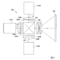
- FIG. 1 is a schematic configuration diagram illustrating a projector according to a first embodiment.
- It is a figure which shows schematic structure of the illuminating device for blue lights which concerns on 2nd Embodiment.
- FIG. 1 is a schematic configuration diagram illustrating a projector according to the present embodiment.
- the projector 100 includes a red light illumination device 101R, a green light illumination device 101G, a blue light illumination device 101B, a red light liquid crystal light valve 102R, and a green light liquid crystal light valve.
- 102G, a blue light liquid crystal light valve 102B, field lenses 106B, 106G, and 106R, a color synthesizing element 103, and a projection optical system 104 are provided.
- each of the red light illumination device 101R, the green light illumination device 101G, and the blue light illumination device 101B corresponds to an “illumination device” in the claims.
- Each of the red light liquid crystal light valve 102R, the green light liquid crystal light valve 102G, and the blue light liquid crystal light valve 102B corresponds to a “light modulation device” in the claims.
- the projector 100 generally operates as follows.
- the light beam LR made of red laser light emitted from the red light illumination device 101R is incident on the red light liquid crystal light valve 102R via the field lens 106R and modulated.
- a light beam LG made of green laser light emitted from the green light illumination device 101G enters the green light liquid crystal light valve 102G via the field lens 106G and is modulated.
- the light beam LB made of blue laser light emitted from the blue light illumination device 101B is incident on the blue light liquid crystal light valve 102B via the field lens 106B and modulated.
- the blue light liquid crystal light valve 102B includes a liquid crystal panel in which a liquid crystal layer is sandwiched between a pair of glass substrates, a light incident side polarizing plate disposed on the light incident side of the liquid crystal panel, and a liquid crystal A light emission side polarizing plate disposed on the light emission side of the panel.
- the operation mode of the liquid crystal panel is not particularly limited, such as a TN mode, a VA mode, and a horizontal electric field mode.
- the liquid crystal light valve for red light and the liquid crystal light valve for blue light have the same configuration.
- the red light modulated by the red light liquid crystal light valve 102R, the green light modulated by the green light liquid crystal light valve 102G, and the blue light modulated by the blue light liquid crystal light valve 102B are incident on the color composition element 103. And synthesized.
- the color synthesizing element 103 is constituted by, for example, a cross dichroic prism.
- the light synthesized by the color synthesizing element 103 is emitted as image light and enlarged and projected onto the screen SCR by the projection optical system 104. In this way, a full color projected image is displayed.
- the red light illuminating device 101R, the green light illuminating device 101G, and the blue light illuminating device 101B differ only in the color of the emitted light, and have the same device configuration.
- a laser light source for red light emits laser light (light beam) having a peak wavelength in a wavelength range of approximately 585 nm to 720 nm.
- the green laser light source emits laser light (light beam) having a peak wavelength in a wavelength range of approximately 495 nm to 585 nm.
- the laser light source for blue light emits laser light (light beam) having a peak wavelength in a wavelength range of approximately 380 nm to 495 nm.
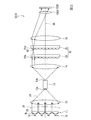
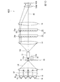
- FIG. 2 is a diagram showing a schematic configuration of the blue light illumination device 101B.
- the field lens 106B and the blue light liquid crystal light valve 102B are also illustrated.
- the blue light illumination device 101 ⁇ / b> B includes a light source device 10, a first collimating optical system 11, a condensing optical system 12 provided at a subsequent stage of the first collimating optical system 11, and condensing optics.
- a superimposing lens 16 provided in the lens.
- the light source device 10 includes a laser light source 19 that emits a blue light beam BL.
- the number of laser light sources 19 is not limited. In the present embodiment, a plurality of laser light sources 19 are two-dimensionally arranged. In FIG. 2, only four laser light sources 19 are illustrated, but the plurality of laser light sources 19 are arranged in a matrix (for example, 4 rows and 4 columns) in a plane perpendicular to the illumination optical axis AX.
- the light source device 10 emits a light beam LB composed of a plurality of light beams BL.
- the first collimating optical system 11 is provided on the light emission side of the light source device 10, and the light beam LB emitted from the light source device 10 is incident thereon.
- the first collimating optical system 11 includes a plurality of collimating lenses 20 arranged in an array.
- Each of the plurality of collimating lenses 20 is disposed corresponding to each of the plurality of laser light sources 19. That is, the plurality of collimating lenses 20 are arranged in a matrix (for example, 4 rows and 4 columns).
- the light beams BL emitted from each of the laser light sources 19 are substantially collimated by the collimating lens 20. Based on such a configuration, the first collimating optical system 11 collimates the light beam LB.
- a collimating optical system in which a plurality of cylindrical lenses arranged in the row direction and a plurality of cylindrical lenses arranged in the column direction are combined is used. Also good.
- the light beam LB transmitted through the first collimating optical system 11 is incident on the condensing optical system 12.
- the condensing optical system 12 makes the light beam LB enter the rod 13 so as to condense.
- Rod 13 has a light incident end face 13a and a light exit end face 13b.
- the light incident end face 13a is disposed at or near the focal position of the condensing optical system 12.
- the light beam LB incident on the light incident end surface 13a of the rod 13 propagates by being totally reflected inside the rod 13, and is emitted from the light emitting end surface 13b. Thereby, the in-plane intensity distribution of the light beam LB emitted from the light emission end face 13b is made uniform.
- the light beam LB whose in-plane intensity distribution is made uniform by the rod 13 enters the second collimating optical system 14.
- the second collimating optical system 14 is composed of one lens, and the light beam LB emitted from the rod 13 is incident thereon.
- the second collimating optical system 14 converts the light beam LB emitted from the rod 13 into parallel light.
- the collimated light beam LB is incident on a lens integrator 15 provided at the subsequent stage of the second collimating optical system 14.
- the lens integrator 15 includes a first lens array 24 and a second lens array 25 provided at a subsequent stage of the first lens array 24.
- the first lens array 24 has a plurality of first small lenses 24a.
- the plurality of first small lenses 24a are arranged in a matrix of a plurality of rows and a plurality of columns in a plane orthogonal to the illumination optical axis AX.
- the first lens array 24 divides the light beam LB emitted from the rod 13 into a plurality of partial light beams.
- each of the first small lenses 24a is substantially similar to the shape of the image forming area of the blue light liquid crystal light valve 102B.
- each of the partial light beams emitted from the first lens array 24 can be efficiently incident on the image forming area of the blue light liquid crystal light valve 102B. Therefore, high light utilization efficiency can be realized.
- the second lens array 25 has a plurality of second small lenses 25a.
- Each of the plurality of first small lenses 24a has the same shape as each of the plurality of second small lenses 25a.
- the first small lens 24a and the second small lens 25a have a one-to-one correspondence with each other, and the plurality of second small lenses 25a are arranged in a matrix of a plurality of rows and a plurality of columns in a plane orthogonal to the illumination optical axis AX. Has been.
- a plurality of images of the light exit end face 13 b of the rod 13 are formed on the lens surface of the second lens array 25.
- the image serves as a secondary light source.
- the second lens array 25 forms an image of the first small lens 24a of the first lens array 24 in the vicinity of the image forming area of the blue light liquid crystal light valve 102B in cooperation with the superimposing lens 16 and the field lens 106B in the subsequent stage. It has a function to image.
- the light beam BL emitted from the laser light source 19 is coherent light, so speckle noise is generated in the projected image.
- the inventor increases the uniformity of the intensity distribution of the secondary light source image formed on the second lens array 25, or It was found that a plurality of secondary light source images should be widely distributed in the two-lens array 25 (the spatial distribution of the plurality of secondary light sources should be expanded). And the structure of this embodiment was completed.
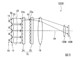
- FIG. 3 is a diagram showing a schematic configuration of a blue light illumination device 101B1 according to a comparative example.
- the blue light illuminating device 101B1 is different from the blue light illuminating device 101B in that it does not have a condensing optical system, a rod, and a second collimating optical system. 3 also shows the field lens 106B and the blue light liquid crystal light valve 102B for convenience of explanation.
- the blue light illumination device 101B1 includes a light source device 10, a first collimating optical system 11, a lens integrator 15, and a superimposing lens 16. Therefore, the light beam LB transmitted through the first collimating optical system 11 is directly incident on the lens integrator 15.
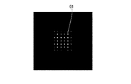
- FIG. 4 is a diagram showing a secondary light source image G1 formed on the lens surface of the second lens array 25 in the comparative example.
- the size of the secondary light source image G1 is small.
- the EP value is also small as described above, so that speckle noise is easily noticeable.
- the blue light illumination device 101B includes a condensing optical system 12, a rod 13, and a second collimating optical system 14. Further, the lens surface of the second lens array 25 (the surface of the second small lens 25a) and the light emitting end surface 13b of the rod 13 are substantially conjugate with each other.
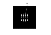
- FIG. 5 is a diagram showing a secondary light source image G2 formed on the lens surface of the second lens array 25 in the present embodiment.
- an image (secondary light source image G ⁇ b> 2) of the light exit end face 13 b of the rod 13 is formed on the lens surface of the second lens array 25.
- the secondary light source image G2 in the present embodiment is larger than the secondary light source image G1 of the comparative example shown in FIG.
- the size of the secondary light source image G2 can be arbitrarily set according to the size of the light exit end face 13b of the rod 13.
- the shape of the light exit end face 13b of the rod 13 and the shape of each of the plurality of second small lenses 25a of the second lens array 25 are similar.
- the secondary light source image G2 can be expanded to the maximum size that can be accommodated inside the contour of the second small lens 25a.
- speckle can be reduced by increasing the size of the secondary light source image G2 formed on the second lens array 25.
- a positional shift may occur between the plurality of laser light sources 19 and the plurality of collimating lenses 20 constituting the light source device 10.
- the light beam LB emitted from the light source device 10 is condensed and incident on the light incident end face 13 a of the rod 13.
- the size of the light incident end face 13a of the rod 13 is sufficiently larger than the positional deviation range of the condensing point of the light beam LB due to the mounting error described above. Therefore, even when a mounting error occurs in the light source device 10, the light beam LB can be incident on the light incident end face 13 a (illuminated object) of the rod 13. Therefore, the light emitted from the light source device 10 can be used efficiently.
- the blue light illumination device 101 ⁇ / b> B of the present embodiment the light use efficiency is not easily affected by mounting errors.
- the superimposing lens 16 provided in the subsequent stage of the lens integrator 15 cooperates with the field lens 106 ⁇ / b> B to emit a plurality of light beams emitted from the second lens array 25, and is a liquid crystal for blue light that is an illuminated area.
- the light valves 102B are overlapped with each other. Thereby, the intensity distribution of the light that illuminates the blue light liquid crystal light valve 102B is made uniform, and the axial symmetry about the illumination optical axis AX is enhanced.
- the secondary light source image G2 formed on the second lens array 25 can be enlarged.
- speckle noise of the image projected by the projector 1 is reduced as compared with the conventional case.
- FIG. 6 is a diagram showing a schematic configuration of a blue light illumination device 201B according to the present embodiment.
- the blue light illumination device 201B includes a light source device 10, a first collimating optical system 11, a condensing optical system 12, a rod 113, a second collimating optical system 14, and a lens integrator 15. And a superimposing lens 16.
- the rod 113 has a light incident end face 113a, a light exit end face 113b, and a diffusing portion 17.
- the blue light illumination device 201 ⁇ / b> B includes a diffusing unit 17.
- the diffusion part 17 is, for example, a concavo-convex structure provided on the surface of the light emission end face 113b.
- the uneven structure is finer than the plurality of first small lenses 24a or second small lenses 25a.
- the diffusing structure is formed by, for example, a microlens formed directly on the surface of the light emitting end surface 113b, an unevenness formed by blasting the surface of the light emitting end surface 113b, or a diffraction element formed on the surface of the light emitting end surface 113b. Composed.
- the diffusion unit 17 diffuses the light beam LB emitted from the light emission end face 113b at a predetermined angle. Since the light beam LB is diffused by the diffusing unit 17, the size of the formation region (a plurality of secondary light source images) on the second lens array 25 on which the plurality of secondary light source images are formed is compared with the case where the diffusing unit 17 is not provided. The spatial distribution of the next light source image becomes large.
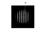
- FIG. 7 is a view showing a secondary light source image formed on the lens surface of the second lens array 25 in the present embodiment.
- the light beam LB is not diffused unlike the blue light illumination device 201B of the first embodiment.
- the size becomes larger than the formation area (see FIG. 5) of the plurality of secondary light source images G2. That is, according to the configuration of the present embodiment, speckle can be further reduced by expanding the spatial distribution of the plurality of secondary light source images G3 than in the first embodiment.
- FIG. 8 is a diagram showing a schematic configuration of a blue light illumination device 301B according to the present embodiment.
- the blue light illumination device 301 ⁇ / b> B includes a light source device 10, a first collimating optical system 11, a condensing optical system 12, a diffusion plate 18, a rod 113, and a second collimating optical system 14.
- the blue light illumination device 301B of the present embodiment is different from the second embodiment in that it includes the diffusion plate 18 provided on the optical path of the light bundle LB between the condensing optical system 12 and the light emission end face 113b. Is different.
- the diffusion plate 18 corresponds to a “diffusion part” recited in the claims.
- the diffusion plate 18 is disposed in the vicinity of the light incident end surface 113a of the rod 113.
- the diffusion plate 18 is made of, for example, a substrate having an uneven structure.
- the concavo-convex structure similarly to the concavo-convex structure of the diffusion portion 17 described above, microlenses, concavo-convex formed by performing blasting, a diffraction element, and the like can be exemplified.
- the diffusion plate 18 diffuses the light beam LB condensed by the condensing optical system 12 and causes the light bundle LB to enter the light incident end surface 113a of the rod 113. Since the light beam LB enters the rod 113 in a diffused state, the in-plane intensity distribution of the light beam LB emitted from the light emission end surface 113b is compared with the case where the diffusion plate 18 is not used (configuration of the second embodiment). Is more uniform. Therefore, a secondary light source image having a more uniform in-plane intensity distribution is formed on the second lens array 25.
- FIG. 9 is a diagram showing a secondary light source image formed on the lens surface of the second lens array 25 in the present embodiment.
- the uniformity of the secondary light source image G4 is higher than the uniformity of the secondary light source image G3 in the second embodiment. Therefore, according to the configuration of the present embodiment, speckle can be further reduced by increasing the uniformity of the secondary light source image G4 as compared to the second embodiment.
- the diffusion plate 18 has a function of increasing the uniformity of the in-plane intensity distribution of the light beam LB, a rod having a relatively low light uniformizing function may be used as the rod 113.
- a rod having a short overall lens length that determines the number of times of total reflection of light may be used.
- the blue light illumination device 301B can be made smaller than the blue light illumination device 101B of the first embodiment.
- the diffusion unit 17 may be omitted.
- FIG. 10 is a diagram showing a schematic configuration of a blue light illumination device 401B according to the present embodiment.
- the illumination device 401B for blue light includes a light source device 10, a first collimating optical system 11, a condensing optical system 12, a rotating diffuser plate 30, a rod 13, and a second collimating optical system. 14, a lens integrator 15, and a superimposing lens 16.
- the blue light illumination device 401B of the present embodiment is different from the first embodiment in that a rotating diffuser plate 30 is provided on the optical path of the light beam LB between the condensing optical system 12 and the light exit end face 13b. ing.
- the rotating diffusion plate 30 corresponds to a “diffusion part” recited in the claims.
- the rotary diffusion plate 30 includes a diffusion plate 31 and a motor 32 that rotates the diffusion plate 31 around a predetermined rotation shaft 31a.
- the diffusion plate 31 has the same configuration as the diffusion plate 18.
- the rotation axis 31a is an axis extending in parallel with the illumination optical axis AX, but the direction of the rotation axis 31a is not particularly limited.
- the rotating diffuser plate 30 changes the diffusion state of the light beam LB transmitted through the diffuser plate 31 with time by rotating the diffuser plate 31 around the rotation axis 31a. That is, according to the configuration of the present embodiment, the speckle pattern changes with time. Since the time-averaged speckle pattern is recognized by the observer, speckle noise is less noticeable than when the diffusion plate 31 does not rotate. Further, the rotating diffusion plate 30 can also reduce interference unevenness due to the use of laser light. Note that the configuration of the present embodiment can provide a remarkable effect when applied to the red light illumination device 101R where speckle noise is most noticeable. Further, the rod 13 may be replaced with the rod 113 described in the second embodiment.
- the present invention is not limited to the contents of the above-described embodiments, and can be appropriately changed without departing from the spirit of the invention.
- the diffusing portion is provided between the condensing optical system 12 and the light incident end surface 13a of the rod 13 or the light emitting end surface 13b is described as an example.
- the position where the part is provided is not limited to this. That is, the diffusing portion may be provided on the light incident end face 13a, or may be provided inside the rod 13 (between the light incident end face 13a and the light emitting end face 13b).
- a projector including three liquid crystal light valves is exemplified, but the present invention may be applied to a projector that displays a color image with one liquid crystal light valve. Further, for example, a digital mirror device may be used as the light modulation device.
- the lighting device according to the present invention is not limited thereto.
- the lighting device according to the present invention can also be applied to lighting fixtures such as automobile headlights.
- Illuminating device for red light 102B ... Liquid crystal light valve for blue light, 102G ... Liquid crystal for green light
- Light valve, 102R Red light liquid crystal light valve, 104 ... Projection optical system, 113 ... Rod, 113a ... Light incident end face, 113b ... Light exit end face 201B ... lighting device for blue light, 301B ... lighting device for blue light, 401B ... lighting device for blue light, LB ... light beam, LG ... light beams, LR ... light beam.
Landscapes
- Physics & Mathematics (AREA)
- General Physics & Mathematics (AREA)
- Optics & Photonics (AREA)
- Engineering & Computer Science (AREA)
- Multimedia (AREA)
- Signal Processing (AREA)
- Projection Apparatus (AREA)
- Non-Portable Lighting Devices Or Systems Thereof (AREA)
Abstract
スペックルを低減させた照明装置を提供する。上記の照明装置を備えたプロジェクターを提供する。 光源装置と、光源装置から射出された光ビームが入射する第1コリメート光学系と、第1コリメート光学系の後段に設けられた集光光学系と、集光光学系の後段に設けられたロッドと、ロッドの後段に設けられた第2コリメート光学系と、第2コリメート光学系の後段に設けられたレンズインテグレーターと、レンズインテグレーターの後段に設けられた重畳レンズと、を備えた照明装置であって、レンズインテグレーターは、第1レンズアレイと、該第1レンズアレイの後段に設けられた第2レンズアレイとを含み、ロッドの光射出端面と第2レンズアレイのレンズ面とが互いに略共役である。
Description
本発明は、照明装置及びプロジェクターに関するものである。
下記特許文献1には、レーザー光源を用いたプロジェクターにおいて、変形可能ミラーを用いてスペックルノイズを低減する技術が開示されている。
下記特許文献2では、スペックルの大きさの指標としてEP値が導入され、EP値を大きくすることでスペックルを低減することが開示されている。
特許文献1に開示のプロジェクターにおいては、変形可能ミラーの製造や動作の制御が容易ではない。そこで、特許文献2に開示されているEP値を大きくすることができる簡易な手段が望まれていた。
本発明の一つの態様は、上記の課題を解決するためになされたものであり、スペックルを低減させた照明装置を提供することを目的の一つとする。本発明の一つの態様は、上記の照明装置を備えたプロジェクターを提供することを目的の一つとする。
本発明の第1態様に従えば、光源装置と、前記光源装置から射出された光ビームが入射する第1コリメート光学系と、前記第1コリメート光学系の後段に設けられた集光光学系と、前記集光光学系の後段に設けられたロッドと、前記ロッドの後段に設けられた第2コリメート光学系と、前記第2コリメート光学系の後段に設けられたレンズインテグレーターと、前記レンズインテグレーターの後段に設けられた重畳レンズと、を備えた照明装置であって、前記レンズインテグレーターは、第1レンズアレイと、該第1レンズアレイの後段に設けられた第2レンズアレイとを含み、前記ロッドの光射出端面と前記第2レンズアレイのレンズ面とが互いに略共役である照明装置が提供される。
第1態様に係る照明装置によれば、第2レンズアレイのレンズ面にロッドの光射出端面の像を形成できる。光射出端面の像は二次光源として働く。よって、ロッドを用いずに第1コリメート光学系からの光をレンズインテグレーターに入射させる場合と比べて、第2レンズアレイに形成される二次光源の像を容易に大きくすることができる。これにより、スペックルを低減することができる。
上記第1態様において、前記集光光学系と前記光射出端面との間における前記光ビームの光路上、又は前記光射出端面に設けられた拡散部をさらに備えるのが好ましい。
第1レンズアレイを備えているため、第2レンズアレイには複数の二次光源像が形成される。拡散部を備えることで、複数の二次光源像が形成される領域が拡大される。よって、スペックルをより低減できる。
第1レンズアレイを備えているため、第2レンズアレイには複数の二次光源像が形成される。拡散部を備えることで、複数の二次光源像が形成される領域が拡大される。よって、スペックルをより低減できる。
上記第1態様において、前記拡散部は、前記集光光学系と前記ロッドの光入射端面との間に設けられ、所定の回転軸の周りに回転可能に構成されているのが好ましい。
この構成によれば、拡散部を透過する光の拡散状態が時間的に変化するため、スペックルパターンが時間的に変化する。時間平均されたスペックルパターンが観察者に認識されるため、拡散部が回転しない場合よりもスペックルノイズが目立ちにくい。また、レーザー光を用いたことによる干渉ムラが低減される。
この構成によれば、拡散部を透過する光の拡散状態が時間的に変化するため、スペックルパターンが時間的に変化する。時間平均されたスペックルパターンが観察者に認識されるため、拡散部が回転しない場合よりもスペックルノイズが目立ちにくい。また、レーザー光を用いたことによる干渉ムラが低減される。
上記第1態様において、前記第2レンズアレイは複数の第2小レンズを有し、前記複数の第2小レンズ各々の形状は、前記光射出端面の形状と相似であるのが好ましい。
この構成によれば、第2小レンズの輪郭の内側に収まる最大の大きさまで二次光源像を拡げることができる。よって、二次光源像を大きくすることでスペックルを低減することができる。
この構成によれば、第2小レンズの輪郭の内側に収まる最大の大きさまで二次光源像を拡げることができる。よって、二次光源像を大きくすることでスペックルを低減することができる。
本発明の第2態様に従えば、上記第1態様に係る照明装置と、前記照明装置からの照明光を画像情報に応じて変調することにより画像光を形成する光変調装置と、前記画像光を投射する投射光学系と、を備えるプロジェクターが提供される。
第2態様に係るプロジェクターは、上記第1態様に係る照明装置を備えるので、スペックルノイズが低減された高い品質の画像を表示できる。
上記第2態様において、前記第1レンズアレイは複数の第1小レンズを有し、前記光変調装置は画像形成領域を有し、複数の前記第1小レンズ各々の形状は、前記画像形成領域の形状と相似であるのが好ましい。
この構成によれば、第1レンズアレイから射出された部分光束各々を光変調装置の画像形成領域に効率良く入射させることができる。よって、高い光利用効率を実現できる。
この構成によれば、第1レンズアレイから射出された部分光束各々を光変調装置の画像形成領域に効率良く入射させることができる。よって、高い光利用効率を実現できる。
以下、本発明の実施の形態について、図面を参照して詳細に説明する。
なお、以下の説明で用いる図面は、特徴をわかりやすくするために、便宜上特徴となる部分を拡大して示している場合があり、各構成要素の寸法比率などが実際と同じであるとは限らない。
なお、以下の説明で用いる図面は、特徴をわかりやすくするために、便宜上特徴となる部分を拡大して示している場合があり、各構成要素の寸法比率などが実際と同じであるとは限らない。
(第1実施形態)
図1は、本実施形態のプロジェクターを示す概略構成図である。
図1に示すように、プロジェクター100は、赤色光用照明装置101Rと、緑色光用照明装置101Gと、青色光用照明装置101Bと、赤色光用液晶ライトバルブ102Rと、緑色光用液晶ライトバルブ102Gと、青色光用液晶ライトバルブ102Bと、フィールドレンズ106B,106G,106Rと、色合成素子103と、投射光学系104と、を備えている。
図1は、本実施形態のプロジェクターを示す概略構成図である。
図1に示すように、プロジェクター100は、赤色光用照明装置101Rと、緑色光用照明装置101Gと、青色光用照明装置101Bと、赤色光用液晶ライトバルブ102Rと、緑色光用液晶ライトバルブ102Gと、青色光用液晶ライトバルブ102Bと、フィールドレンズ106B,106G,106Rと、色合成素子103と、投射光学系104と、を備えている。
本実施形態において、赤色光用照明装置101R、緑色光用照明装置101Gおよび青色光用照明装置101B各々は、特許請求の範囲の「照明装置」に対応する。赤色光用液晶ライトバルブ102R、緑色光用液晶ライトバルブ102Gおよび青色光用液晶ライトバルブ102B各々は、特許請求の範囲の「光変調装置」に対応する。
プロジェクター100は、概略すると以下のように動作する。
赤色光用照明装置101Rから射出された赤色のレーザー光からなる光線束LRは、フィールドレンズ106Rを介して赤色光用液晶ライトバルブ102Rに入射して変調される。同様に、緑色光用照明装置101Gから射出された緑色のレーザー光からなる光線束LGは、フィールドレンズ106Gを介して緑色光用液晶ライトバルブ102Gに入射して変調される。青色光用照明装置101Bから射出された青色のレーザー光からなる光線束LBは、フィールドレンズ106Bを介して青色光用液晶ライトバルブ102Bに入射して変調される。
赤色光用照明装置101Rから射出された赤色のレーザー光からなる光線束LRは、フィールドレンズ106Rを介して赤色光用液晶ライトバルブ102Rに入射して変調される。同様に、緑色光用照明装置101Gから射出された緑色のレーザー光からなる光線束LGは、フィールドレンズ106Gを介して緑色光用液晶ライトバルブ102Gに入射して変調される。青色光用照明装置101Bから射出された青色のレーザー光からなる光線束LBは、フィールドレンズ106Bを介して青色光用液晶ライトバルブ102Bに入射して変調される。
青色光用液晶ライトバルブ102Bは、図示を省略するが、一対のガラス基板の間に液晶層が挟持された液晶パネルと、液晶パネルの光入射側に配置される光入射側偏光板と、液晶パネルの光射出側に配置される光射出側偏光板と、を備える。液晶パネルの動作モードは、TNモード、VAモード、横電界モード等、特に限定されるものではない。赤色光用液晶ライトバルブ、青色光用液晶ライトバルブも、同様の構成である。
赤色光用液晶ライトバルブ102Rにより変調された赤色光、緑色光用液晶ライトバルブ102Gにより変調された緑色光、および青色光用液晶ライトバルブ102Bにより変調された青色光は、色合成素子103に入射して合成される。色合成素子103は例えばクロスダイクロイックプリズムにより構成されている。色合成素子103により合成された光は、画像光として射出され、投射光学系104によりスクリーンSCRに拡大投写される。このようにして、フルカラーの投写画像が表示される。
以下、プロジェクター100の各構成要素について説明する。
赤色光用照明装置101R、緑色光用照明装置101G、および青色光用照明装置101Bは、射出される光の色が異なるだけであり、装置構成は同様である。一例として、赤色光用のレーザー光源は、概ね585nm~720nmの波長域にピーク波長を持つレーザー光(光ビーム)を射出する。緑色光用のレーザー光源は、概ね495nm~585nmの波長域にピーク波長を持つレーザー光(光ビーム)を射出する。青色光用のレーザー光源は、概ね380nm~495nmの波長域にピーク波長を持つレーザー光(光ビーム)を射出する。
赤色光用照明装置101R、緑色光用照明装置101G、および青色光用照明装置101Bは、射出される光の色が異なるだけであり、装置構成は同様である。一例として、赤色光用のレーザー光源は、概ね585nm~720nmの波長域にピーク波長を持つレーザー光(光ビーム)を射出する。緑色光用のレーザー光源は、概ね495nm~585nmの波長域にピーク波長を持つレーザー光(光ビーム)を射出する。青色光用のレーザー光源は、概ね380nm~495nmの波長域にピーク波長を持つレーザー光(光ビーム)を射出する。
したがって、以下では、青色光用照明装置101Bについてのみ説明し、赤色光用照明装置101Rおよび緑色光用照明装置101Gについては説明を省略する。
図2は青色光用照明装置101Bの概略構成を示す図である。なお、図2においては、説明の都合上、フィールドレンズ106B及び青色光用液晶ライトバルブ102Bも図示している。
図2に示すように、青色光用照明装置101Bは、光源装置10と、第1コリメート光学系11と、第1コリメート光学系11の後段に設けられた集光光学系12と、集光光学系12の後段に設けられたロッド13と、ロッド13の後段に設けられた第2コリメート光学系14と、第2コリメート光学系14の後段に設けられたレンズインテグレーター15と、レンズインテグレーター15の後段に設けられた重畳レンズ16と、を備えている。
光源装置10は、青色の光ビームBLを射出するレーザー光源19を備える。なお、レーザー光源19の数は限定されない。本実施形態では、複数のレーザー光源19が二次元的に配列されている。図2では、4個のレーザー光源19のみを図示するが、複数のレーザー光源19は、照明光軸AXに垂直な面内において、マトリクス状(例えば4行4列)に配列されている。光源装置10は複数の光ビームBLからなる光線束LBを射出する。
第1コリメート光学系11は光源装置10の光射出側に設けられており、光源装置10から射出された光線束LBが入射する。第1コリメート光学系11は、アレイ状に配列された複数のコリメートレンズ20を備えている。複数のコリメートレンズ20の各々は、複数のレーザー光源19の各々に対応して配置されている。すなわち、複数のコリメートレンズ20は、マトリクス状(例えば4行4列)に配列されている。レーザー光源19の各々から射出された光ビームBLは、コリメートレンズ20によって略平行化される。このような構成に基づき、第1コリメート光学系11は光線束LBを平行化する。
なお、上記の第1コリメート光学系11の構成に代えて、例えば行方向に配列された複数のシリンドリカルレンズと、列方向に配列された複数のシリンドリカルレンズと、を組み合わせたコリメート光学系を用いてもよい。
集光光学系12には第1コリメート光学系11を透過した光線束LBが入射する。集光光学系12は光線束LBを集光させるようにロッド13に入射させる。
ロッド13光入射端面13aと光射出端面13bとを有する。光入射端面13aは集光光学系12の焦点位置、または焦点近傍に配置されている。
ロッド13の光入射端面13aに入射した光線束LBは、ロッド13の内部を全反射することで伝播し、光射出端面13bから射出される。これにより、光射出端面13bから射出された光線束LBの面内強度分布が均一化される。ロッド13により面内強度分布が均一化された光線束LBは第2コリメート光学系14に入射する。
第2コリメート光学系14は一つのレンズからなり、ロッド13から射出された光線束LBが入射する。第2コリメート光学系14はロッド13から射出された光線束LBを平行光に変換する。平行化された光線束LBは、第2コリメート光学系14の後段に設けられたレンズインテグレーター15に入射する。
レンズインテグレーター15は、第1レンズアレイ24と、該第1レンズアレイ24の後段に設けられた第2レンズアレイ25と、を含む。
第1レンズアレイ24は複数の第1小レンズ24aを有する。複数の第1小レンズ24aは、照明光軸AXと直交する面内に複数行、複数列のマトリクス状に配列されている。第1レンズアレイ24は、ロッド13から射出された光線束LBを複数の部分光束に分割する。
第1小レンズ24a各々の形状は、青色光用液晶ライトバルブ102Bの画像形成領域の形状と略相似形となっている。これにより、第1レンズアレイ24から射出された部分光束各々を青色光用液晶ライトバルブ102Bの画像形成領域に効率良く入射させることができる。よって、高い光利用効率を実現できる。
第2レンズアレイ25は複数の第2小レンズ25aを有する。複数の第1小レンズ24a各々の形状は、複数の第2小レンズ25a各々の形状と同じである。第1小レンズ24a及び第2小レンズ25aは互いに1対1で対応しており、複数の第2小レンズ25aは照明光軸AXと直交する面内に複数行、複数列のマトリクス状に配列されている。
第2レンズアレイ25のレンズ面には、ロッド13の光射出端面13bの像が複数形成される。当該像は二次光源として働く。
第2レンズアレイ25は、後段の重畳レンズ16及びフィールドレンズ106Bと協働して、第1レンズアレイ24の第1小レンズ24aの像を青色光用液晶ライトバルブ102Bの画像形成領域近傍に結像させる機能を有する。
ところで、本実施形態のプロジェクター100において、レーザー光源19から発せられた光ビームBLはコヒーレント光であることから、投写画像にスペックルノイズが発生する。
本発明者は、特開2015-64444号公報に記載されているEP値を大きくするには、第2レンズアレイ25に形成される二次光源像の強度分布の均一性を高める、或いは、第2レンズアレイ25に複数の二次光源像を広く分布させる(複数の二次光源の空間分布を拡げる)ようにすればよいとの知見を得た。そして、本実施形態の構成を完成させた。
ここで、比較例を参照しながら、本実施形態の構成による効果について説明する。
図3は比較例に係る青色光用照明装置101B1の概略構成を示す図である。青色光用照明装置101B1は、集光光学系と、ロッドと、第2コリメート光学系とを有しない点において青色光用照明装置101Bと異なっている。なお、図3においても、説明の都合上、フィールドレンズ106B及び青色光用液晶ライトバルブ102Bも図示している。
図3に示すように、比較例に係る青色光用照明装置101B1は、光源装置10と、第1コリメート光学系11と、レンズインテグレーター15と、重畳レンズ16と、を備えている。そのため、第1コリメート光学系11を透過した光線束LBはレンズインテグレーター15に直接入射する。
この青色光用照明装置101B1において、レーザー光源19と第2レンズアレイ25とが共役関係にあるため、第2レンズアレイ25にレーザー光源19の像(二次光源像G1)が形成される。
図4は比較例において第2レンズアレイ25のレンズ面に形成される二次光源像G1を示した図である。図4に示すように、レーザー光源19からの光は第2レンズアレイ25上で結像するため、二次光源像G1の大きさは小さい。
このように二次光源像G1の大きさが小さいと、上述のようにEP値も小さくなるため、スペックルノイズが目立ち易くなる。
このように二次光源像G1の大きさが小さいと、上述のようにEP値も小さくなるため、スペックルノイズが目立ち易くなる。
これに対し、本実施形態に係る青色光用照明装置101Bは、集光光学系12と、ロッド13と、第2コリメート光学系14とを備えている。また、第2レンズアレイ25のレンズ面(第2小レンズ25aの表面)とロッド13の光射出端面13bとは互いに略共役となっている。
図5は本実施形態において第2レンズアレイ25のレンズ面に形成される二次光源像G2を示した図である。図5に示すように、第2レンズアレイ25のレンズ面にはロッド13の光射出端面13bの像(二次光源像G2)が形成される。図4に示した比較例の二次光源像G1よりも、本実施形態における二次光源像G2の方が大きい。
ここで、二次光源像G2の大きさは、ロッド13の光射出端面13bの大きさによって任意に設定可能である。
本実施形態において、ロッド13の光射出端面13bの形状と、第2レンズアレイ25の複数の第2小レンズ25a各々の形状とは相似である。このようにすれば、第2小レンズ25aの輪郭の内側に収まる最大の大きさまで二次光源像G2を拡げることができる。
本実施形態によれば、第2レンズアレイ25に形成される二次光源像G2のサイズを大きくすることでスペックルを低減することができる。
ここで、光源装置10を構成する複数のレーザー光源19と複数のコリメートレンズ20との間で、位置ズレ(実装誤差)が生じることがある。
本実施形態においては、光源装置10から射出した光線束LBを集光してロッド13の光入射端面13aに入射させている。ロッド13の光入射端面13aのサイズは、上述の実装誤差による光線束LBの集光点の位置ずれ範囲よりも十分に大きい。
そのため、光源装置10において実装誤差が生じた場合であっても、ロッド13の光入射端面13a内(被照明物)に光線束LBを入射させることができる。したがって、光源装置10から射出した光を効率良く利用することができる。
本実施形態の青色光用照明装置101Bにおいて、光利用効率は実装誤差の影響を受け難い。
そのため、光源装置10において実装誤差が生じた場合であっても、ロッド13の光入射端面13a内(被照明物)に光線束LBを入射させることができる。したがって、光源装置10から射出した光を効率良く利用することができる。
本実施形態の青色光用照明装置101Bにおいて、光利用効率は実装誤差の影響を受け難い。
図2に戻って、レンズインテグレーター15の後段に設けられた重畳レンズ16は、第2レンズアレイ25から射出された複数の光束をフィールドレンズ106Bと協働して被照明領域である青色光用液晶ライトバルブ102B上で互いに重畳させる。これにより、青色光用液晶ライトバルブ102Bを照明する光の強度分布が均一化されるとともに、照明光軸AX周りの軸対称性が高められる。
以上説明したように、本実施形態によれば、第2レンズアレイ25に形成される二次光源像G2を大きくすることができる。その結果、プロジェクター1が投写する画像のスペックルノイズは従来よりも低減されている。
(第2実施形態)
続いて、第2実施形態に係る照明装置について説明する。本実施形態においても、青色光用照明装置についてのみ説明し、赤色光用照明装置および緑色光用照明装置については説明を省略する。なお、第1実施形態と共通の構成及び部材については同じ符号を付し、その説明については省略若しくは簡略にする。
続いて、第2実施形態に係る照明装置について説明する。本実施形態においても、青色光用照明装置についてのみ説明し、赤色光用照明装置および緑色光用照明装置については説明を省略する。なお、第1実施形態と共通の構成及び部材については同じ符号を付し、その説明については省略若しくは簡略にする。
図6は本実施形態に係る青色光用照明装置201Bの概略構成を示す図である。
図6に示すように、青色光用照明装置201Bは、光源装置10と、第1コリメート光学系11と、集光光学系12と、ロッド113と、第2コリメート光学系14と、レンズインテグレーター15と、重畳レンズ16と、を備えている。
図6に示すように、青色光用照明装置201Bは、光源装置10と、第1コリメート光学系11と、集光光学系12と、ロッド113と、第2コリメート光学系14と、レンズインテグレーター15と、重畳レンズ16と、を備えている。
ロッド113は、光入射端面113aと、光射出端面113bと、拡散部17と、を有する。第1実施形態の青色光用照明装置201Bとは異なり、青色光用照明装置201Bは拡散部17を備えている。拡散部17は、例えば、光射出端面113bの表面に設けられた凹凸構造である。凹凸構造は、複数の第1小レンズ24a或いは第2小レンズ25aよりも微細である。拡散構造は、例えば、光射出端面113bの表面に直接形成したマイクロレンズや、光射出端面113bの表面にブラスト処理を施すことで形成した凹凸や、光射出端面113bの表面に形成した回折素子から構成される。
拡散部17は、光射出端面113bから射出される光線束LBを所定の角度で拡散させる。光線束LBは拡散部17により拡散されるため、拡散部17を有しない場合に比べて、第2レンズアレイ25上における複数の二次光源像が形成される形成領域の大きさ(複数の二次光源像の空間分布)は大きくなる。
図7は本実施形態において第2レンズアレイ25のレンズ面に形成される二次光源像を示した図である。図7に示すように、拡散部17によって拡散された光線束LBによる複数の二次光源像G3の形成領域は、第1実施形態の青色光用照明装置201Bのように光線束LBが拡散されない場合の複数の二次光源像G2の形成領域(図5参照)よりもサイズが大きくなる。すなわち、本実施形態の構成によれば、第1実施形態よりも複数の二次光源像G3の空間分布を拡げることでスペックルをより低減することができる。
(第3実施形態)
続いて、第3実施形態に係る照明装置について説明する。本実施形態においても、青色光用照明装置についてのみ説明し、赤色光用照明装置および緑色光用照明装置については説明を省略する。なお、第2実施形態と共通の構成及び部材については同じ符号を付し、その説明については省略若しくは簡略にする。
続いて、第3実施形態に係る照明装置について説明する。本実施形態においても、青色光用照明装置についてのみ説明し、赤色光用照明装置および緑色光用照明装置については説明を省略する。なお、第2実施形態と共通の構成及び部材については同じ符号を付し、その説明については省略若しくは簡略にする。
図8は本実施形態に係る青色光用照明装置301Bの概略構成を示す図である。
図8に示すように、青色光用照明装置301Bは、光源装置10と、第1コリメート光学系11と、集光光学系12と、拡散板18と、ロッド113と、第2コリメート光学系14と、レンズインテグレーター15と、重畳レンズ16と、を備えている。
図8に示すように、青色光用照明装置301Bは、光源装置10と、第1コリメート光学系11と、集光光学系12と、拡散板18と、ロッド113と、第2コリメート光学系14と、レンズインテグレーター15と、重畳レンズ16と、を備えている。
すなわち、本実施形態の青色光用照明装置301Bは、集光光学系12と光射出端面113bとの間における光線束LBの光路上に設けられた拡散板18を備える点で第2実施形態と異なっている。拡散板18は特許請求の範囲に記載の「拡散部」に相当する。
本実施形態において、拡散板18は、ロッド113の光入射端面113aの近傍に配置されている。拡散板18は、例えば凹凸構造を有する基板からなる。凹凸構造としては、上述の拡散部17の凹凸構造と同様、マイクロレンズや、ブラスト処理を施すことで形成した凹凸や、回折素子等を例示できる。
拡散板18は、集光光学系12により集光された光線束LBを拡散させてロッド113の光入射端面113aに入射させる。光線束LBは拡散した状態でロッド113に入射するため、光射出端面113bから射出された光線束LBの面内強度分布は、拡散板18を用いない場合(第2実施形態の構成)に比べ、より均一化されている。よって、より均一性が高い面内強度分布を有する二次光源像が第2レンズアレイ25上に形成される。
図9は本実施形態において第2レンズアレイ25のレンズ面に形成される二次光源像を示した図である。図9に示すように、光線束LBは拡散板18によって拡散されているため、二次光源像G4の均一性は第2実施形態における二次光源像G3の均一性よりも高い。よって、本実施形態の構成によれば、第2実施形態よりも二次光源像G4の均一性を高めることでスペックルをより低減することができる。
なお、拡散板18は光線束LBの面内強度分布の均一性を高める機能を持っているので、ロッド113として光均一化機能が比較的低いロッドを用いてもよい。たとえば、光の全反射回数を決めるレンズ全長が短いロッドを用いてもよい。これによれば、青色光用照明装置301Bを第1実施形態の青色光用照明装置101Bよりも小型化することができる。また、拡散板18を備えているため、拡散部17を省略してもよい。
(第4実施形態)
続いて、第4実施形態に係る照明装置について説明する。本実施形態においても、青色光用照明装置についてのみ説明し、赤色光用照明装置および緑色光用照明装置については説明を省略する。なお、第3実施形態と共通の構成及び部材については同じ符号を付し、その説明については省略若しくは簡略にする。
続いて、第4実施形態に係る照明装置について説明する。本実施形態においても、青色光用照明装置についてのみ説明し、赤色光用照明装置および緑色光用照明装置については説明を省略する。なお、第3実施形態と共通の構成及び部材については同じ符号を付し、その説明については省略若しくは簡略にする。
図10は本実施形態に係る青色光用照明装置401Bの概略構成を示す図である。
図10に示すように、青色光用照明装置401Bは、光源装置10と、第1コリメート光学系11と、集光光学系12と、回転拡散板30と、ロッド13と、第2コリメート光学系14と、レンズインテグレーター15と、重畳レンズ16と、を備えている。
図10に示すように、青色光用照明装置401Bは、光源装置10と、第1コリメート光学系11と、集光光学系12と、回転拡散板30と、ロッド13と、第2コリメート光学系14と、レンズインテグレーター15と、重畳レンズ16と、を備えている。
すなわち、本実施形態の青色光用照明装置401Bは、集光光学系12と光射出端面13bとの間における光線束LBの光路上に、回転拡散板30を備える点で第1実施形態と異なっている。本実施形態において、回転拡散板30は特許請求の範囲に記載の「拡散部」に相当する。
本実施形態において、回転拡散板30は、拡散板31と、拡散板31を所定の回転軸31aの周りに回転させるモーター32とを備えている。拡散板31は、上記拡散板18と同様の構成を有する。なお、本実施形態において、回転軸31aは照明光軸AXと平行に延びる軸であるが、回転軸31aの方向は特に限定されない。
回転拡散板30は、回転軸31aの周りに拡散板31を回転させることで、該拡散板31を透過する光線束LBの拡散状態を時間的に変化させる。すなわち、本実施形態の構成によれば、スペックルパターンが時間的に変化する。時間平均されたスペックルパターンが観察者に認識されるため、拡散板31が回転しない場合よりもスペックルノイズが目立ちにくい。
また、回転拡散板30は、レーザー光を用いたことによる干渉ムラを低減することもできる。
なお、本実施形態の構成は、最もスペックルノイズが目立ち易い赤色光用照明装置101Rに適用した場合に顕著な効果を得ることができる。また、ロッド13を第2実施形態で説明したロッド113に置き換えてもよい。
また、回転拡散板30は、レーザー光を用いたことによる干渉ムラを低減することもできる。
なお、本実施形態の構成は、最もスペックルノイズが目立ち易い赤色光用照明装置101Rに適用した場合に顕著な効果を得ることができる。また、ロッド13を第2実施形態で説明したロッド113に置き換えてもよい。
以上、本発明の実施形態について説明したが、本発明は上記実施形態の内容に限定されることはなく、発明の主旨を逸脱しない範囲において適宜変更可能である。
例えば、上記第2、第3、第4実施形態では、集光光学系12とロッド13の光入射端面13aとの間或いは光射出端面13bに拡散部を設ける場合を例に挙げたが、拡散部を設ける位置はこれに限定されない。すなわち、拡散部は光入射端面13a上に設けてもよく、またはロッド13の内部(光入射端面13aと光射出端面13bとの間)に設けても良い。
例えば、上記第2、第3、第4実施形態では、集光光学系12とロッド13の光入射端面13aとの間或いは光射出端面13bに拡散部を設ける場合を例に挙げたが、拡散部を設ける位置はこれに限定されない。すなわち、拡散部は光入射端面13a上に設けてもよく、またはロッド13の内部(光入射端面13aと光射出端面13bとの間)に設けても良い。
上記実施形態では、3つの液晶ライトバルブを備えるプロジェクターを例示したが、1つの液晶ライトバルブでカラー映像を表示するプロジェクターに適用してもよい。さらに、光変調装置としては、例えばデジタルミラーデバイスを用いてもよい。
また、上記実施形態では、本発明による照明装置をプロジェクターに応用する例を示したが、これに限られない。本発明による照明装置を自動車用ヘッドライトなどの照明器具にも適用できる。
1…プロジェクター、10…光源装置、11…第1コリメート光学系、12…集光光学系、13…ロッド、13a…光入射端面、13b…光射出端面、14…第2コリメート光学系、15…レンズインテグレーター、16…重畳レンズ、17…拡散部、18…拡散板、19…レーザー光源、24…第1レンズアレイ、24a…第1小レンズ、25…第2レンズアレイ、25a…第2小レンズ、30…回転拡散板、100…プロジェクター、101B…青色光用照明装置、101G…緑色光用照明装置、101R…赤色光用照明装置、102B…青色光用液晶ライトバルブ、102G…緑色光用液晶ライトバルブ、102R…赤色光用液晶ライトバルブ、104…投射光学系、113…ロッド、113a…光入射端面、113b…光射出端面、201B…青色光用照明装置、301B…青色光用照明装置、401B…青色光用照明装置、LB…光線束、LG…光線束、LR…光線束。
Claims (6)
- 光源装置と、
前記光源装置から射出された光ビームが入射する第1コリメート光学系と、
前記第1コリメート光学系の後段に設けられた集光光学系と、
前記集光光学系の後段に設けられたロッドと、
前記ロッドの後段に設けられた第2コリメート光学系と、
前記第2コリメート光学系の後段に設けられたレンズインテグレーターと、
前記レンズインテグレーターの後段に設けられた重畳レンズと、を備えた照明装置であって、
前記レンズインテグレーターは、第1レンズアレイと、該第1レンズアレイの後段に設けられた第2レンズアレイとを含み、
前記ロッドの光射出端面と前記第2レンズアレイのレンズ面とが互いに略共役である
照明装置。 - 前記集光光学系と前記光射出端面との間における前記光ビームの光路上、又は前記光射出端面に設けられた拡散部をさらに備える
請求項1に記載の照明装置。 - 前記拡散部は、前記集光光学系と前記ロッドの光入射端面との間に設けられ、所定の回転軸の周りに回転可能に構成されている
請求項2に記載の照明装置。 - 前記第2レンズアレイは複数の第2小レンズを有し、
前記複数の第2小レンズ各々の形状は、前記光射出端面の形状と相似である
請求項1乃至3のいずれか一項に記載の照明装置。 - 請求項1乃至4のいずれか一項に記載の照明装置と、
前記照明装置からの照明光を画像情報に応じて変調することにより画像光を形成する光変調装置と、
前記画像光を投射する投射光学系と、を備える
プロジェクター。 - 前記第1レンズアレイは複数の第1小レンズを有し、
前記光変調装置は画像形成領域を有し、
複数の前記第1小レンズ各々の形状は、前記画像形成領域の形状と相似である
請求項5に記載のプロジェクター。
Priority Applications (1)
| Application Number | Priority Date | Filing Date | Title |
|---|---|---|---|
| US16/330,262 US10534250B2 (en) | 2016-09-05 | 2017-08-23 | Illumination device and projector |
Applications Claiming Priority (2)
| Application Number | Priority Date | Filing Date | Title |
|---|---|---|---|
| JP2016-172993 | 2016-09-05 | ||
| JP2016172993A JP6737084B2 (ja) | 2016-09-05 | 2016-09-05 | 照明装置及びプロジェクター |
Publications (1)
| Publication Number | Publication Date |
|---|---|
| WO2018043247A1 true WO2018043247A1 (ja) | 2018-03-08 |
Family
ID=61301796
Family Applications (1)
| Application Number | Title | Priority Date | Filing Date |
|---|---|---|---|
| PCT/JP2017/030131 Ceased WO2018043247A1 (ja) | 2016-09-05 | 2017-08-23 | 照明装置及びプロジェクター |
Country Status (3)
| Country | Link |
|---|---|
| US (1) | US10534250B2 (ja) |
| JP (1) | JP6737084B2 (ja) |
| WO (1) | WO2018043247A1 (ja) |
Cited By (2)
| Publication number | Priority date | Publication date | Assignee | Title |
|---|---|---|---|---|
| CN108415213A (zh) * | 2018-04-29 | 2018-08-17 | 中国华录集团有限公司 | 一种激光投影显示用匀光板透镜一体化系统 |
| US10915014B1 (en) * | 2019-08-28 | 2021-02-09 | Seiko Epson Corporation | Illumination optical device and projector |
Families Citing this family (4)
| Publication number | Priority date | Publication date | Assignee | Title |
|---|---|---|---|---|
| WO2019182073A1 (ja) * | 2018-03-20 | 2019-09-26 | Agc株式会社 | ホモジェナイザ、照明光学系および照明装置 |
| EP3598591A1 (en) * | 2018-07-17 | 2020-01-22 | Koninklijke Philips N.V. | Laser arrangement with reduced building height |
| CN115280234A (zh) | 2020-03-18 | 2022-11-01 | 夏普Nec显示器解决方案株式会社 | 光源设备和投影仪 |
| JP2025035875A (ja) * | 2023-09-04 | 2025-03-14 | セイコーエプソン株式会社 | プロジェクター |
Citations (2)
| Publication number | Priority date | Publication date | Assignee | Title |
|---|---|---|---|---|
| JP2014182207A (ja) * | 2013-03-18 | 2014-09-29 | Seiko Epson Corp | 照明装置及びプロジェクター |
| JP2015169675A (ja) * | 2014-03-04 | 2015-09-28 | セイコーエプソン株式会社 | 照明装置およびプロジェクター |
Family Cites Families (15)
| Publication number | Priority date | Publication date | Assignee | Title |
|---|---|---|---|---|
| KR20100106487A (ko) | 2007-12-19 | 2010-10-01 | 옵티카 리미티드 | 광학계 및 방법 |
| JP2010152176A (ja) | 2008-12-25 | 2010-07-08 | Mitsubishi Electric Corp | 投写型表示装置 |
| JP2012088451A (ja) | 2010-10-18 | 2012-05-10 | Sony Corp | 照明装置および表示装置 |
| JP2013015762A (ja) | 2011-07-06 | 2013-01-24 | Sony Corp | 照明光学系および画像表示装置 |
| CN103034297A (zh) * | 2011-09-30 | 2013-04-10 | 鸿富锦精密工业(深圳)有限公司 | 数据存储器固定装置 |
| JP6160117B2 (ja) | 2013-02-21 | 2017-07-12 | セイコーエプソン株式会社 | 光源装置およびプロジェクター |
| JP2014164175A (ja) | 2013-02-26 | 2014-09-08 | Seiko Epson Corp | 照明装置、及びプロジェクター |
| JP2014170034A (ja) | 2013-03-01 | 2014-09-18 | Panasonic Corp | 画像表示装置 |
| CN104111532B (zh) * | 2013-04-20 | 2017-08-29 | 深圳市绎立锐光科技开发有限公司 | 发光装置及相关光源系统 |
| JP2015064444A (ja) | 2013-09-24 | 2015-04-09 | セイコーエプソン株式会社 | プロジェクター |
| JP2014178693A (ja) | 2014-04-08 | 2014-09-25 | Sony Corp | 照明装置および表示装置 |
| JP2015230866A (ja) | 2014-06-06 | 2015-12-21 | Necディスプレイソリューションズ株式会社 | 照明光学系及び投写型表示装置 |
| JP2016057644A (ja) | 2015-12-25 | 2016-04-21 | ソニー株式会社 | 照明光学系および画像表示装置 |
| US10816883B2 (en) * | 2016-11-29 | 2020-10-27 | Panasonici Intellectual Property Management Co., Ltd. | Light source system and projection display apparatus |
| JP6511546B1 (ja) * | 2018-01-10 | 2019-05-15 | 株式会社ライトショー・テクノロジー | 光源装置および投射型表示装置 |
-
2016
- 2016-09-05 JP JP2016172993A patent/JP6737084B2/ja active Active
-
2017
- 2017-08-23 WO PCT/JP2017/030131 patent/WO2018043247A1/ja not_active Ceased
- 2017-08-23 US US16/330,262 patent/US10534250B2/en active Active
Patent Citations (2)
| Publication number | Priority date | Publication date | Assignee | Title |
|---|---|---|---|---|
| JP2014182207A (ja) * | 2013-03-18 | 2014-09-29 | Seiko Epson Corp | 照明装置及びプロジェクター |
| JP2015169675A (ja) * | 2014-03-04 | 2015-09-28 | セイコーエプソン株式会社 | 照明装置およびプロジェクター |
Cited By (4)
| Publication number | Priority date | Publication date | Assignee | Title |
|---|---|---|---|---|
| CN108415213A (zh) * | 2018-04-29 | 2018-08-17 | 中国华录集团有限公司 | 一种激光投影显示用匀光板透镜一体化系统 |
| US10915014B1 (en) * | 2019-08-28 | 2021-02-09 | Seiko Epson Corporation | Illumination optical device and projector |
| CN112445053A (zh) * | 2019-08-28 | 2021-03-05 | 精工爱普生株式会社 | 照明光学装置和投影仪 |
| CN112445053B (zh) * | 2019-08-28 | 2022-03-11 | 精工爱普生株式会社 | 照明光学装置和投影仪 |
Also Published As
| Publication number | Publication date |
|---|---|
| US10534250B2 (en) | 2020-01-14 |
| US20190196317A1 (en) | 2019-06-27 |
| JP2018041564A (ja) | 2018-03-15 |
| JP6737084B2 (ja) | 2020-08-05 |
Similar Documents
| Publication | Publication Date | Title |
|---|---|---|
| JP6737084B2 (ja) | 照明装置及びプロジェクター | |
| JP6160117B2 (ja) | 光源装置およびプロジェクター | |
| JP6744041B2 (ja) | 光源装置、プロジェクター及びスペックル低減方法 | |
| JP6090875B2 (ja) | 照明光学系及びプロジェクタ | |
| US20150309399A1 (en) | Illumination apparatus and projection-type image display apparatus having the same | |
| JP6565362B2 (ja) | 光源装置およびプロジェクター | |
| JP6255680B2 (ja) | 照明光源装置とこれを用いた投射装置 | |
| JPWO2020137749A1 (ja) | 光源装置および投写型映像表示装置 | |
| US9891514B2 (en) | Light source apparatus and projection display apparatus | |
| JP6330147B2 (ja) | 光源装置及び投写型映像表示装置 | |
| WO2014192115A1 (ja) | 光源装置および投写型表示装置 | |
| JP2020177070A (ja) | 光源装置及び投写型表示装置 | |
| JP2018084757A (ja) | 照明装置及びプロジェクター | |
| JP6582708B2 (ja) | 光源装置、照明装置およびプロジェクター | |
| JP2018021990A (ja) | 光源装置、及びプロジェクター | |
| JP2021047363A (ja) | プロジェクター | |
| JP6318670B2 (ja) | プロジェクター | |
| JP2017146553A (ja) | 照明装置及びプロジェクター | |
| JP6323072B2 (ja) | 照明装置およびプロジェクター | |
| US11474424B2 (en) | Light source device and projector | |
| WO2019187948A1 (ja) | プロジェクタ | |
| JP4893780B2 (ja) | 照明装置及びこれを備えたプロジェクタ | |
| JP2016184064A (ja) | デスペックル照明装置およびデスペックル照明方法、投写型表示装置 | |
| US20240329508A1 (en) | Illumination device and projector | |
| JP2008102193A (ja) | 偏光変換素子、照明装置及び画像表示装置 |
Legal Events
| Date | Code | Title | Description |
|---|---|---|---|
| 121 | Ep: the epo has been informed by wipo that ep was designated in this application |
Ref document number: 17846252 Country of ref document: EP Kind code of ref document: A1 |
|
| NENP | Non-entry into the national phase |
Ref country code: DE |
|
| 122 | Ep: pct application non-entry in european phase |
Ref document number: 17846252 Country of ref document: EP Kind code of ref document: A1 |