WO2018043248A1 - Procédé de fabrication de stabilisateur et structure de joint pour liaison de stabilisateur - Google Patents
Procédé de fabrication de stabilisateur et structure de joint pour liaison de stabilisateur Download PDFInfo
- Publication number
- WO2018043248A1 WO2018043248A1 PCT/JP2017/030140 JP2017030140W WO2018043248A1 WO 2018043248 A1 WO2018043248 A1 WO 2018043248A1 JP 2017030140 W JP2017030140 W JP 2017030140W WO 2018043248 A1 WO2018043248 A1 WO 2018043248A1
- Authority
- WO
- WIPO (PCT)
- Prior art keywords
- stabilizer
- stud
- ball
- link
- hole
- Prior art date
- Legal status (The legal status is an assumption and is not a legal conclusion. Google has not performed a legal analysis and makes no representation as to the accuracy of the status listed.)
- Ceased
Links
Images







Classifications
-
- B—PERFORMING OPERATIONS; TRANSPORTING
- B60—VEHICLES IN GENERAL
- B60G—VEHICLE SUSPENSION ARRANGEMENTS
- B60G21/00—Interconnection systems for two or more resiliently-suspended wheels, e.g. for stabilising a vehicle body with respect to acceleration, deceleration or centrifugal forces
- B60G21/02—Interconnection systems for two or more resiliently-suspended wheels, e.g. for stabilising a vehicle body with respect to acceleration, deceleration or centrifugal forces permanently interconnected
- B60G21/04—Interconnection systems for two or more resiliently-suspended wheels, e.g. for stabilising a vehicle body with respect to acceleration, deceleration or centrifugal forces permanently interconnected mechanically
- B60G21/05—Interconnection systems for two or more resiliently-suspended wheels, e.g. for stabilising a vehicle body with respect to acceleration, deceleration or centrifugal forces permanently interconnected mechanically between wheels on the same axle but on different sides of the vehicle, i.e. the left and right wheel suspensions being interconnected
- B60G21/055—Stabiliser bars
- B60G21/0551—Mounting means therefor
-
- B—PERFORMING OPERATIONS; TRANSPORTING
- B60—VEHICLES IN GENERAL
- B60G—VEHICLE SUSPENSION ARRANGEMENTS
- B60G21/00—Interconnection systems for two or more resiliently-suspended wheels, e.g. for stabilising a vehicle body with respect to acceleration, deceleration or centrifugal forces
- B60G21/02—Interconnection systems for two or more resiliently-suspended wheels, e.g. for stabilising a vehicle body with respect to acceleration, deceleration or centrifugal forces permanently interconnected
- B60G21/04—Interconnection systems for two or more resiliently-suspended wheels, e.g. for stabilising a vehicle body with respect to acceleration, deceleration or centrifugal forces permanently interconnected mechanically
- B60G21/05—Interconnection systems for two or more resiliently-suspended wheels, e.g. for stabilising a vehicle body with respect to acceleration, deceleration or centrifugal forces permanently interconnected mechanically between wheels on the same axle but on different sides of the vehicle, i.e. the left and right wheel suspensions being interconnected
- B60G21/055—Stabiliser bars
-
- B—PERFORMING OPERATIONS; TRANSPORTING
- B60—VEHICLES IN GENERAL
- B60G—VEHICLE SUSPENSION ARRANGEMENTS
- B60G7/00—Pivoted suspension arms; Accessories thereof
- B60G7/005—Ball joints
-
- F—MECHANICAL ENGINEERING; LIGHTING; HEATING; WEAPONS; BLASTING
- F16—ENGINEERING ELEMENTS AND UNITS; GENERAL MEASURES FOR PRODUCING AND MAINTAINING EFFECTIVE FUNCTIONING OF MACHINES OR INSTALLATIONS; THERMAL INSULATION IN GENERAL
- F16C—SHAFTS; FLEXIBLE SHAFTS; ELEMENTS OR CRANKSHAFT MECHANISMS; ROTARY BODIES OTHER THAN GEARING ELEMENTS; BEARINGS
- F16C11/00—Pivots; Pivotal connections
- F16C11/04—Pivotal connections
- F16C11/06—Ball-joints; Other joints having more than one degree of angular freedom, i.e. universal joints
- F16C11/0604—Construction of the male part
-
- F—MECHANICAL ENGINEERING; LIGHTING; HEATING; WEAPONS; BLASTING
- F16—ENGINEERING ELEMENTS AND UNITS; GENERAL MEASURES FOR PRODUCING AND MAINTAINING EFFECTIVE FUNCTIONING OF MACHINES OR INSTALLATIONS; THERMAL INSULATION IN GENERAL
- F16C—SHAFTS; FLEXIBLE SHAFTS; ELEMENTS OR CRANKSHAFT MECHANISMS; ROTARY BODIES OTHER THAN GEARING ELEMENTS; BEARINGS
- F16C11/00—Pivots; Pivotal connections
- F16C11/04—Pivotal connections
- F16C11/06—Ball-joints; Other joints having more than one degree of angular freedom, i.e. universal joints
- F16C11/0695—Mounting of ball-joints, e.g. fixing them to a connecting rod
-
- B—PERFORMING OPERATIONS; TRANSPORTING
- B60—VEHICLES IN GENERAL
- B60G—VEHICLE SUSPENSION ARRANGEMENTS
- B60G2202/00—Indexing codes relating to the type of spring, damper or actuator
- B60G2202/10—Type of spring
- B60G2202/13—Torsion spring
- B60G2202/135—Stabiliser bar and/or tube
-
- B—PERFORMING OPERATIONS; TRANSPORTING
- B60—VEHICLES IN GENERAL
- B60G—VEHICLE SUSPENSION ARRANGEMENTS
- B60G2204/00—Indexing codes related to suspensions per se or to auxiliary parts
- B60G2204/10—Mounting of suspension elements
- B60G2204/12—Mounting of springs or dampers
- B60G2204/122—Mounting of torsion springs
- B60G2204/1224—End mounts of stabiliser on wheel suspension
-
- B—PERFORMING OPERATIONS; TRANSPORTING
- B60—VEHICLES IN GENERAL
- B60G—VEHICLE SUSPENSION ARRANGEMENTS
- B60G2204/00—Indexing codes related to suspensions per se or to auxiliary parts
- B60G2204/40—Auxiliary suspension parts; Adjustment of suspensions
- B60G2204/416—Ball or spherical joints
-
- B—PERFORMING OPERATIONS; TRANSPORTING
- B60—VEHICLES IN GENERAL
- B60G—VEHICLE SUSPENSION ARRANGEMENTS
- B60G2204/00—Indexing codes related to suspensions per se or to auxiliary parts
- B60G2204/40—Auxiliary suspension parts; Adjustment of suspensions
- B60G2204/422—Links for mounting suspension elements
-
- B—PERFORMING OPERATIONS; TRANSPORTING
- B60—VEHICLES IN GENERAL
- B60G—VEHICLE SUSPENSION ARRANGEMENTS
- B60G2206/00—Indexing codes related to the manufacturing of suspensions: constructional features, the materials used, procedures or tools
- B60G2206/01—Constructional features of suspension elements, e.g. arms, dampers, springs
- B60G2206/40—Constructional features of dampers and/or springs
- B60G2206/42—Springs
- B60G2206/427—Stabiliser bars or tubes
-
- B—PERFORMING OPERATIONS; TRANSPORTING
- B60—VEHICLES IN GENERAL
- B60G—VEHICLE SUSPENSION ARRANGEMENTS
- B60G2206/00—Indexing codes related to the manufacturing of suspensions: constructional features, the materials used, procedures or tools
- B60G2206/01—Constructional features of suspension elements, e.g. arms, dampers, springs
- B60G2206/80—Manufacturing procedures
- B60G2206/82—Joining
- B60G2206/8201—Joining by welding
-
- B—PERFORMING OPERATIONS; TRANSPORTING
- B60—VEHICLES IN GENERAL
- B60G—VEHICLE SUSPENSION ARRANGEMENTS
- B60G2206/00—Indexing codes related to the manufacturing of suspensions: constructional features, the materials used, procedures or tools
- B60G2206/01—Constructional features of suspension elements, e.g. arms, dampers, springs
- B60G2206/80—Manufacturing procedures
- B60G2206/82—Joining
- B60G2206/8209—Joining by deformation
- B60G2206/82092—Joining by deformation by press-fitting
-
- B—PERFORMING OPERATIONS; TRANSPORTING
- B60—VEHICLES IN GENERAL
- B60G—VEHICLE SUSPENSION ARRANGEMENTS
- B60G2206/00—Indexing codes related to the manufacturing of suspensions: constructional features, the materials used, procedures or tools
- B60G2206/01—Constructional features of suspension elements, e.g. arms, dampers, springs
- B60G2206/80—Manufacturing procedures
- B60G2206/82—Joining
- B60G2206/821—Joining by gluing
-
- B—PERFORMING OPERATIONS; TRANSPORTING
- B60—VEHICLES IN GENERAL
- B60G—VEHICLE SUSPENSION ARRANGEMENTS
- B60G2600/00—Indexing codes relating to particular elements, systems or processes used on suspension systems or suspension control systems
- B60G2600/44—Vibration noise suppression
-
- F—MECHANICAL ENGINEERING; LIGHTING; HEATING; WEAPONS; BLASTING
- F16—ENGINEERING ELEMENTS AND UNITS; GENERAL MEASURES FOR PRODUCING AND MAINTAINING EFFECTIVE FUNCTIONING OF MACHINES OR INSTALLATIONS; THERMAL INSULATION IN GENERAL
- F16C—SHAFTS; FLEXIBLE SHAFTS; ELEMENTS OR CRANKSHAFT MECHANISMS; ROTARY BODIES OTHER THAN GEARING ELEMENTS; BEARINGS
- F16C2326/00—Articles relating to transporting
- F16C2326/01—Parts of vehicles in general
- F16C2326/05—Vehicle suspensions, e.g. bearings, pivots or connecting rods used therein
Definitions
- the present invention relates to a stabilizer manufacturing method for manufacturing a stabilizer to which a stabilizer link is joined by joining a stabilizer link for connecting between a suspension device and a stabilizer provided in a vehicle to the stabilizer, and a stabilizer link joining structure. .
- the vehicle is equipped with a suspension device that absorbs and reduces shock and vibration transmitted from the road surface via wheels to the vehicle body, and a stabilizer for increasing the roll rigidity of the vehicle body.
- a rod-shaped member called a stabilizer link is used in the vehicle.
- the stabilizer link includes a support bar and ball joints provided at both ends of the support bar.
- the stabilizer link according to Patent Document 1 includes a ball stud having a ball portion and a stud portion, and a housing that is provided at both ends of the support bar and rotatably accommodates the ball portion of the ball stud.
- a resin ball sheet is provided so as to be interposed between the inner wall of the housing and the ball portion of the ball stud.
- the present invention was devised in view of the above circumstances, and an object of the present invention is to provide a method of manufacturing a stabilizer capable of realizing a rigid joint that does not particularly require a measure for separating the stabilizer link from the stabilizer.
- Another object of the present invention is to provide a stabilizer link joint structure capable of realizing a firm joint that does not particularly require a measure for separating the stabilizer link from the stabilizer.
- Another object of the present invention is to provide a stabilizer link joining structure capable of suppressing the vibration and noise and maintaining the ride comfort of the vehicle.
- a stabilizer manufacturing method is a stabilizer in which a stabilizer link is joined by joining a suspension link provided in a vehicle and a stabilizer link for connecting the stabilizer to the stabilizer. It is a manufacturing method of the stabilizer which manufactures.
- the stabilizer link includes a support bar and ball joints provided at both ends of the support bar.
- the ball joint includes a ball stud having a ball portion and a stud portion, and a housing that rotatably supports the ball portion of the ball stud.
- the stabilizer is composed of a metal rod-shaped member. Attachment portions to which the stabilizer link is joined are provided at both ends of the stabilizer.
- the attachment portion is provided with a through hole through which the stud portion of the ball stud is inserted. The stabilizer link is joined to the stabilizer by press-fitting the stud portion of the ball stud into the through hole of the attachment portion.
- the stud link of the ball stud is press-fitted into the through hole of the mounting portion to join the stabilizer link to the stabilizer. It is possible to realize a solid joint that is not particularly required.
- the stabilizer link joining structure according to the present invention (12) is a stabilizer link joining structure in which a stabilizer link for connecting a suspension device and a stabilizer provided in a vehicle is joined to the stabilizer.
- the stabilizer link includes a support bar and ball joints provided at both ends of the support bar.
- the ball joint includes a ball stud having a ball portion and a stud portion, and a housing that rotatably supports the ball portion of the ball stud.
- the stabilizer is composed of a metal rod-shaped member. At both ends of the stabilizer, attachment portions to which the stabilizer link is joined are provided.
- the mounting portion is provided with a through hole through which the stud portion of the ball stud is inserted. The stud portion of the ball stud is joined to the mounting portion by being press-fitted into the through hole of the mounting portion.
- the stud portion of the ball stud is joined to the attachment portion by being press-fitted into the through hole of the attachment portion, so that the stabilizer link is separated from the stabilizer. It is possible to realize a solid joint that does not require any special measures.
- the stabilizer link joining structure according to the present invention (16) is a stabilizer link joining structure for joining a stabilizer link for connecting a suspension device and a stabilizer provided in a vehicle to the stabilizer.
- the stabilizer link includes a support bar and ball joints provided at both ends of the support bar.
- the ball joint includes a ball stud having a ball portion and a stud portion, and a housing that rotatably supports the ball portion of the ball stud.
- the stabilizer is composed of a metal rod-shaped member. At both ends of the stabilizer, attachment portions to which the stabilizer link is joined are provided.
- the mounting portion is provided with a through hole through which the stud portion of the ball stud is inserted.
- the stud portion of the ball stud is joined to the attachment portion with an elastic member interposed between the stud portion and the through hole of the attachment portion.
- the stud portion of the ball stud is joined to the attachment portion with an elastic member interposed between the stud portion and the through hole of the attachment portion. And the ride comfort of the vehicle can be kept good.
- the present invention it is possible to provide a stabilizer manufacturing method and a stabilizer link joining structure capable of realizing a firm joint that does not particularly require a measure for separating the stabilizer link from the stabilizer.
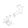
- FIG. 1 It is a perspective view showing the manufacturing method of the stabilizer which concerns on Example 3 of 6th Embodiment of this invention, and the joining structure of a stabilizer link. It is principal part sectional drawing showing the junction structure of the stabilizer link which concerns on 7th Embodiment of this invention. It is a front view showing the joining structure of the stabilizer link which concerns on 7th Embodiment of this invention seen from the arrow X direction shown in FIG.
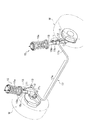
- FIG. 1 is a perspective view illustrating a state in which the stabilizer link 11 is attached to the vehicle.
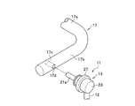
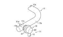
- 2A and 2B are perspective views showing a stabilizer manufacturing method and a stabilizer link joining structure according to the first embodiment of the present invention.
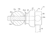
- FIG. 3A is a cross-sectional view of a principal part showing a stabilizer manufacturing method and a stabilizer link joining structure according to the first embodiment of the present invention.
- the suspension device 15 includes a coil spring 15a and a shock absorber 15b.
- the left and right suspension devices 15 are connected via a stabilizer 17 made of a substantially U-shaped spring steel rod or the like.
- the stabilizer 17 is bent from both ends of the torsion bar portion 17a and the torsion bar portion 17a. And a pair of arm portions 17b extending.
- the stabilizer 17 and the shock absorber 15b that supports the wheel W are connected via a stabilizer link 11.
- the connection is the same on the left and right wheels W side.
- the stabilizer link 11 is configured by providing ball joints 13 at both ends of a substantially linear support bar 12 made of a metal such as steel.
- the ball joint 13 includes a ball stud 21 made of metal such as steel and a housing 23 made of resin, for example, as shown in FIG. 3A.
- the ball stud 21 has a cylindrical stud portion 21a at one end portion and a spherical ball portion 21b at the other end portion.
- the stud portion 21a and the ball portion 21b are joined by welding.
- the stud portion 21a and the ball portion 21b may be integrally formed.
- the housing 23 is provided at both ends of the support bar 12, and is configured to rotatably support the ball portion 21b of the ball stud 21.
- the resin material of the housing 23 for example, fiber reinforced plastic FRP (Fiber-Reinforced Plastics) or carbon fiber reinforced plastic CFRP (Carbon Fiber-Reinforced Plastics) is preferably used.
- the housing 23 is not limited to resin and may be made of metal.
- the configuration of the pair of ball joints 13 is the same.
- the stud portion 21a of the ball stud 21 has a flange portion 21a1 as shown in FIG. 3A.
- the flange portion 21a1 will be described in detail later, but caulking portions 22-1 to 2-3 of the stud portion 21a (see Examples 1 to 3 of the second embodiment described later) or welded portions 24-1 to 3 (described later). It has a function of creating a restraining force for the mounting portion 17c acting in the axial direction of the stud portion 21a in cooperation with Examples 1 to 3) of the third embodiment.
- the shape of the flange portion 21a1 is not particularly limited.
- a curved shape along the outer peripheral wall of the mounting portion 17c that can exhibit the above function at a high level may be adopted.
- a circular dust cover 27 made of an elastic body such as rubber is mounted so as to cover these gaps.
- the dust cover 27 plays a role of preventing rainwater, dust and the like from entering the ball joint 13.
- one of the pair of ball joints 13 is fastened and fixed to the bracket 15c of the shock absorber 15b by screw joining. Further, as shown in FIGS. 1, 2A, 2B, and 3A, for example, the other ball joint 13 is manufactured with respect to the mounting portion 17c of the arm portion 17b of the stabilizer 17 according to the embodiment of the present invention. It is joined using the method and the joint structure of the stabilizer link. This will be described in detail below.
- FIGS. 2A, 2B, and 3A A stabilizer manufacturing method and a stabilizer link joining structure according to the first embodiment will be described with reference to FIGS. 2A, 2B, and 3A.
- the mounting portion 17c of the arm portion 17b of the stabilizer 17 has a through-hole (corresponding to the “through-hole” in the present invention) 17d having a shape in which a cylinder just fits.
- the through hole 17d is formed so as to be oriented in a direction perpendicular to the longitudinal direction of the arm portion 17b.
- the stud 21a of the ball stud 21 is inserted through the through hole 17d.
- the outer diameter dimension of the stud portion 21a is substantially equal to or slightly smaller than the inner diameter dimension of the through hole 17d.
- the stabilizer link 11 is joined to the stabilizer 17 by press-fitting the stud portion 21a of the ball stud 21 into the through hole 17d of the mounting portion 17c.
- the frictional force generated between the outer wall surface of the stud portion 21a and the inner wall surface of the through hole 17d is used.
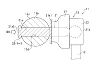
- FIG. 3B is a cross-sectional view of a principal part showing a stabilizer manufacturing method and a stabilizer link joining structure according to the second embodiment of the present invention.
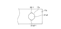
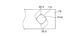
- 4A to 4C are front views respectively showing a stabilizer manufacturing method and a stabilizer link joint structure according to Examples 1 to 3 of the second embodiment of the present invention as viewed from the direction of arrow IIIB shown in FIG. 3B. .
- the through-side end portion 21a2 of the stud portion 21a is inserted in the state where the stud portion 21a of the ball stud 21 is passed through the through-hole 17d of the mounting portion 17c.
- the stabilizer link 11 is joined to the stabilizer 17 by caulking (see FIG. 3B).
- the stud-side end portion 21 a 2 of the stud portion 21 a having a circular shape in front view is point-symmetric.
- the caulking portion 22-1 is formed by caulking these two points.
- the caulking portion 22-1 cooperates with the flange portion 21a1 of the stud portion 21a to restrain the cylindrical mounting portion 17c of the arm portion 17b of the stabilizer 17 in the axial direction of the stud portion 21a. Acts like
- the stud-side end portion 21 a 2 having a circular shape in front view of the stud portion 21 a is point-symmetric.
- the caulking portion 22-2 is formed by caulking these four points.
- the caulking portion 22-2 cooperates with the flange portion 21a1 of the stud portion 21a in the same manner as the caulking portion 22-1 and has a columnar mounting portion 17c included in the arm portion 17b of the stabilizer 17. Is constrained in the axial direction of the stud portion 21a.
- the entire edge of the through-side end portion 21 a 2 having a circular shape when viewed from the front of the stud portion 21 a is formed.
- the caulking portion 22-3 is formed by caulking around the circumference. As shown in FIG. 3B, the caulking portion 22-3 cooperates with the flange portion 21a1 of the stud portion 21a in the same manner as the caulking portions 22-1 and 2-1, and is attached to the columnar shape of the arm portion 17b of the stabilizer 17.
- the portion 17c acts to restrain the stud portion 21a in the axial direction.
- the penetrating side end portion 21a2 of the stud portion 21a is caulked.
- the caulking portions 22-1 to 2-3 are formed by plastic deformation of the penetrating side end portion 21a2.
- the caulking portions 22-1 to 3-3 of the stud portion 21a and the flange portion 21a1 By the cooperation, the binding force acting on the mounting portion 17c acting in the axial direction of the stud portion 21a can realize a firm joint that does not particularly require a measure for joining the stabilizer link 11 to the stabilizer 17.
- FIG. 5A is a cross-sectional view of a principal part showing a stabilizer manufacturing method and a stabilizer link joining structure according to a third embodiment of the present invention.
- FIGS. 5B to 5D are front views respectively showing a stabilizer manufacturing method and a stabilizer link joining structure according to Examples 1 to 3 of the third embodiment of the present invention viewed from the direction of the arrow VA shown in FIG. 5A. .
- the stud portion 21 a has a point-symmetric shape in the through-side end portion 21 a 2 having a circular shape when viewed from the front. These four points are welded to the mounting portion 17c to form a welded portion 24-2. As shown in FIG. 5A, the welded portion 24-2 cooperates with the flange portion 21a1 of the stud portion 21a to cooperate with the flange portion 21a1 of the stud portion 21a, and has a columnar mounting portion 17c that the arm portion 17b of the stabilizer 17 has. Is constrained in the axial direction of the stud portion 21a.
- the entire edge of the through-side end portion 21a2 having a circular shape when viewed from the front of the stud portion 21a is formed.
- the weld 24-3 is formed by welding over the circumference.
- the welded portion 24-3 cooperates with the flange portion 21a1 of the stud portion 21a to restrain the cylindrical mounting portion 17c of the arm portion 17b of the stabilizer 17 in the axial direction of the stud portion 21a. Acts like
- the through-side end portion 21a2 of the stud portion 21a is welded to the mounting portion 17c.
- the welded portions 24-1 to 24-3 are formed.
- the welded portions 24-1 to 3 and the flange portion 21a1 of the stud portion 21a By the cooperation, the binding force acting on the mounting portion 17c acting in the axial direction of the stud portion 21a can realize a firm joint that does not particularly require a measure for joining the stabilizer link 11 to the stabilizer 17.
- FIG. 6 is principal part sectional drawing showing the manufacturing method of the stabilizer which concerns on 4th Embodiment of this invention, and the joining structure of a stabilizer link.
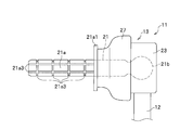
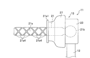
- FIG. 7A and FIG. 7B are explanatory views showing the stud portion 21a of the ball stud 21 used in the stabilizer manufacturing method and the stabilizer link joining structure according to the fourth embodiment of the present invention.
- the stabilizer link 11 is joined to the stabilizer 17 by adhering the outer peripheral wall to the inner peripheral wall of the through hole 17d using an adhesive 26.
- the outer peripheral wall of the stud portion 21a (corresponding to the “adhesive surface of the adhesive” of the present invention). ) are engraved with receiving grooves 21a3 and 21a4 for the adhesive 26, respectively.
- the storage grooves 21a3 and 21a4 of the adhesive 26 serve to store the surplus adhesive 26 and to supply the adhesive 26 to the insufficient part, thereby making the amount of the adhesive 26 uniform on the application surface. .
- FIG. 7A the outer peripheral wall of the stud portion 21a (corresponding to the “adhesive surface of the adhesive” of the present invention). ) are engraved with receiving grooves 21a3 and 21a4 for the adhesive 26, respectively.
- the storage grooves 21a3 and 21a4 of the adhesive 26 serve to store the surplus adhesive 26 and to supply the adhesive 26 to the insufficient part, thereby making the amount of the adhesive 26 uniform on the application surface. .
- the accommodation groove 21a3 of the adhesive 26 is provided so as to extend in the direction along the axial direction of the stud portion 21a and in the direction around the axis of the stud portion 21a.
- the accommodation groove 21a4 of the adhesive 26 is provided so as to extend in the clockwise direction and the counterclockwise direction, respectively, in the spiral direction of the stud portion 21a.
- the stabilizer link 11 is bonded by bonding the outer peripheral wall of the stud portion 21a to the inner peripheral wall of the through hole 17d using the adhesive 26. Since the stabilizer 17 is joined to the stabilizer 17, it is possible to easily realize a firm joint that does not particularly require measures for joining the stabilizer link 11 to the stabilizer 17.
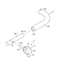
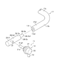
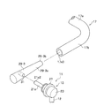
- FIGS. 8A to 8C are perspective views respectively showing a stabilizer manufacturing method and a stabilizer link joining structure according to Examples 1 to 3 of the fifth embodiment of the present invention.
- the stabilizer manufacturing method and the stabilizer link joining structure according to the first to fourth embodiments are used when the stabilizer link 11 is joined to the solid stabilizer 17.
- the stabilizer manufacturing method and the stabilizer link joining structure according to Examples 1 to 3 of the fifth embodiment are similar to the stabilizer link 11 with respect to the hollow tubular stabilizer 17, as shown in FIGS. 8A to 8C. Is different from the stabilizer manufacturing method and the stabilizer link joining structure according to the first to fourth embodiments.
- the arm portion 17b of the stabilizer 17 has on the other hand, substantially cylindrical mounting portions 29-1 to 29-3 are provided separately.
- the substantially cylindrical mounting portion 17 c is formed by the arm portion 17 b in the stabilizer 17. And is provided integrally.
- the material of the attachment portions 29-1 to 29-3 is not particularly limited, and for example, a metal such as iron or a resin (including carbon fiber reinforced plastic) may be appropriately employed.
- the mounting portion 29-1 according to Example 1 of the fifth embodiment is formed in a substantially cylindrical shape.
- a through-hole 31 (corresponding to the “through-hole” of the present invention) 31 having a shape in which a cylinder just fits is provided in the attachment portion 29-1 according to the first embodiment.
- the through hole 31 is formed so as to be oriented in a direction orthogonal to the longitudinal direction of the attachment portion 29-1.
- the stud portion 21 a of the ball stud 21 is inserted into the through hole 31.
- the outer diameter dimension of the stud portion 21 a is substantially equal to or slightly smaller than the inner diameter dimension of the through hole 31.
- the outer diameter dimension of the mounting portion 29-1 according to the first embodiment is substantially equal to or slightly smaller than the inner diameter dimension of the arm portion 17b in the stabilizer 17. Yes.
- the attachment portion 29-1 according to the first embodiment is joined to the arm portion 17b of the stabilizer 17 by press-fitting the outer peripheral wall portion 29-1a of the attachment portion 29-1 into the inner peripheral wall portion 17e1 of the arm portion 17b.
- the inner peripheral wall portion 17e1 of the arm portion 17b and the outer peripheral wall portion 29-1a of the attachment portion 29-1 may be adhesively bonded using an adhesive.
- a configuration in which the arm portion 17b is crimped so as to crush the attachment portion 29-1 in a state where the attachment portion 29-1 is inserted into the hollow space of the arm portion 17b may be employed.
- a portion where the arm portion 17b and the attachment portion 29-1 are adjacent may be welded.
- the mounting portion 29-2 according to Example 2 of the fifth embodiment is formed in a substantially cylindrical shape in appearance as the mounting portion 29-1 according to Example 1.
- the attachment portion 29-2 according to the second embodiment includes a substantially cylindrical large-diameter portion 29-2a and a small-diameter portion 29-2b that are coaxially connected.
- the large diameter portion 29-2a of the mounting portion 29-2 according to the second embodiment has a through hole 31 similar to the mounting portion 29-1 according to the first embodiment. .
- the outer diameter size of the small diameter portion 29-2b of the mounting portion 29-2 according to the second embodiment is substantially equal to the inner diameter size of the arm portion 17b in the stabilizer 17, as shown in FIG. 8B, or , Formed slightly smaller.
- the mounting portion 29-2 according to the second embodiment is configured by pressing the outer peripheral wall portion 29-2b1 of the small-diameter portion 29-2b of the mounting portion 29-2 into the inner peripheral wall portion 17e2 of the arm portion 17b. Is joined to the arm portion 17b.
- the flange portion 29-2c generated by the outer diameter difference between the large diameter portion 29-2a and the small diameter portion 29-2b is abutted against the end surface 17f of the arm portion 17b.
- the outer peripheral wall portion 29-2a1 of the large-diameter portion 29-2a and the outer peripheral wall portion 17b1 of the arm portion 17b of the mounting portion 29-2 are configured to be substantially flush with each other.
- the inner peripheral wall portion 17e2 of the arm portion 17b and the outer peripheral wall portion 29-2b1 of the small diameter portion 29-2b may be adhesively bonded using an adhesive.
- a configuration in which the arm portion 17b is caulked so as to crush the small diameter portion 29-2b in a state where the small diameter portion 29-2b of the attachment portion 29-2 is inserted into the hollow space of the arm portion 17b may be employed.
- a portion where the arm portion 17b and the small diameter portion 29-2b are adjacent may be welded.
- the attachment portion 29-3 according to Example 3 of the fifth embodiment is substantially circular in appearance as the attachment portions 29-1, 2 according to Example 1 or 2. It is formed in a column shape.
- the attachment portion 29-3 according to the third embodiment has a wedge-shaped outer peripheral wall portion 29-3a as shown in FIG. 8C.
- the outer diameter of the tip portion 29-3b facing the inner peripheral wall portion 17e3 of the arm portion 17b in the stabilizer 17 is as shown in FIG. 8C. It is formed smaller than the dimensions.
- the attachment portion 29-3 according to the third embodiment is inserted into the arm portion 17b of the stabilizer 17 by press-fitting the wedge-shaped outer peripheral wall portion 29-3a of the attachment portion 29-3 into the inner peripheral wall portion 17e3 of the arm portion 17b. Be joined.
- the inner peripheral wall portion 17e3 of the arm portion 17b and the wedge-shaped outer peripheral wall portion 29-3a of the attachment portion 29-3 may be adhesively bonded using an adhesive.
- the adjacent portion between the arm portion 17b and the attachment portion 29-3 may be welded. Absent.
- the through holes 31 of the attachment portions 29-1 to 29-3 joined to the arm portion 17b of the stabilizer 17 are provided.
- the stabilizer link 11 is joined to the stabilizer 17 by press-fitting the stud portion 21a of the ball stud 21 (with the stabilizer manufacturing method and the stabilizer link joining structure according to the first embodiment).
- the stud portion 21a of the ball stud 21 is passed through the through holes 31 of the attachment portions 29-1 to 29-3 joined to the arm portion 17b of the stabilizer 17.
- the stabilizer link 11 is joined to the stabilizer 17 by caulking the penetrating end portion 21a2 of the stud portion 21a in the state of being used (using the stabilizer manufacturing method and the stabilizer link joining structure according to the second embodiment). Also good.
- the stud portion 21a of the ball stud 21 is passed through the through holes 31 of the attachment portions 29-1 to 29-3 joined to the arm portion 17b of the stabilizer 17.
- the through-side end 21a2 (see FIG. 5A) of the stud 21a is welded to the mounting portion 17c (the stabilizer manufacturing method and the stabilizer link joining structure according to the third embodiment are used).
- the link 11 may be joined to the stabilizer 17.
- the stud portion 21a of the ball stud 21 is passed through the through holes 31 of the attachment portions 29-1 to 29-3 joined to the arm portion 17b of the stabilizer 17.
- the outer peripheral wall of the stud portion 21a is bonded to the inner peripheral wall of the through-hole 31 using an adhesive (not shown) (using the stabilizer manufacturing method and the stabilizer link connecting structure according to the third embodiment). Accordingly, the stabilizer link 11 may be joined to the stabilizer 17.
- the arm portion 17b of the stabilizer 17 is provided.
- the attachment portions 29-1 to 29-3 separate from the stud portion 21a of the ball stud 21 as an intermediate joining member, it is possible to easily realize a firm joint that does not particularly require a measure for joining the stabilizer link 11 to the stabilizer 17.
- the attachment portions 29 are joined to both ends of the hollow tubular stabilizer 17 so as to close the hollow space, an event that liquid such as water enters the hollow space of the stabilizer 17 is prevented, and generation of rust and the like is prevented. The following effects can also be obtained.
- FIGS. 9A to 9C are perspective views respectively showing a stabilizer manufacturing method and a stabilizer link joint structure according to Examples 1 to 3 of the sixth embodiment of the present invention.
- the stabilizer manufacturing method and the stabilizer link joining structure according to Examples 1 to 3 of the fifth embodiment include the stabilizer link 11 with respect to the hollow tubular stabilizer 17, the arm portion 17 b of the stabilizer 17, and the ball stud 21.
- the stud portion 21a is used for joining via attachment portions 29-1 to 3-3 (see FIGS. 8A to 8C) that are separate from the stud portion 21a.
- the stabilizer manufacturing method and the stabilizer link joining structure according to Examples 1 to 3 of the sixth embodiment are similar to the stabilizer link 11 with respect to the hollow tubular stabilizer 17 as shown in FIGS. 9A to 9C.
- the stud portion 21a of the ball stud 21 is provided.
- substantially cylindrical attachment portions 33-1 to 33-1 extending in a substantially L shape are integrally provided.
- the material of the attachment portions 33-1 to 33-1 is not particularly limited.
- a metal such as iron and a resin (including fiber reinforced plastic and carbon fiber reinforced plastic) may be appropriately employed.
- the outer diameter of the mounting portion 33-1 according to Example 1 of the sixth embodiment is substantially equal to or slightly smaller than the inner diameter of the arm portion 17b in the stabilizer 17. It is formed small.
- the attachment portion 33-1 according to the first embodiment is joined to the arm portion 17b of the stabilizer 17 by press-fitting the outer peripheral wall portion 33-1a of the attachment portion 33-1 into the inner peripheral wall portion 17e1 of the arm portion 17b.
- the inner peripheral wall portion 17e1 of the arm portion 17b and the outer peripheral wall portion 33-1a of the attachment portion 33-1 may be adhesively bonded using an adhesive.
- a configuration in which the arm portion 17b is crimped so as to crush the attachment portion 33-1 in a state where the attachment portion 33-1 is inserted into the hollow space of the arm portion 17b may be employed.
- a portion where the arm portion 17b and the mounting portion 33-1 are adjacent may be welded.
- the mounting portion 33-2 according to Example 2 of the sixth embodiment is formed in a substantially cylindrical shape in appearance as the mounting portion 33-1 according to Example 1. ing.
- the attachment portion 33-2 according to the second embodiment has a substantially cylindrical large-diameter portion 33-2a and a small-diameter portion 33-2b that are coaxially connected.
- the outer diameter size of the small diameter portion 33-2b of the mounting portion 33-2 according to the second embodiment is substantially the same as the inner diameter size of the arm portion 17b in the stabilizer 17, as shown in FIG. 9B, or , Formed slightly smaller.
- the mounting portion 33-2 according to the second embodiment presses the outer peripheral wall portion 33-2b1 of the small-diameter portion 33-2b of the mounting portion 33-2 into the inner peripheral wall portion 17e2 of the arm portion 17b. Is joined to the arm portion 17b.
- the flange portion 33-2c generated by the difference in outer diameter between the large diameter portion 33-2a and the small diameter portion 33-2b is abutted against the end surface 17f of the arm portion 17b.
- the outer peripheral wall portion 33-2a1 of the large-diameter portion 33-2a and the outer peripheral wall 17b1 of the arm portion 17b of the attachment portion 33-2 are configured to be substantially flush with each other.
- the inner peripheral wall portion 17e2 of the arm portion 17b and the outer peripheral wall portion 33-2b1 of the small diameter portion 33-2b may be adhesively bonded using an adhesive. Further, a configuration may be adopted in which the arm portion 17b is crimped so as to crush the small diameter portion 33-2b in a state where the small diameter portion 33-2b of the attachment portion 33-2 is inserted into the hollow space of the arm portion 17b. Further, in a state where the small diameter portion 33-2b of the attachment portion 33-2 is inserted into the hollow space of the arm portion 17b, a portion where the arm portion 17b and the small diameter portion 33-2b are adjacent may be joined by welding.
- the attachment portion 33-3 according to Example 3 of the sixth embodiment is substantially circular in appearance as the attachment portions 33-1 and 3-2 according to Example 1 or 2. It is formed in a column shape.
- the attachment portion 33-3 according to the third embodiment has a wedge-shaped outer peripheral wall portion 33-3a as shown in FIG. 9C.
- the outer diameter of the tip portion 33-3b facing the inner peripheral wall portion 17e3 of the arm portion 17b in the stabilizer 17 is as shown in FIG. 9C. It is formed smaller than the dimensions.
- the mounting portion 33-3 according to the third embodiment is inserted into the arm portion 17b of the stabilizer 17 by press-fitting the wedge-shaped outer peripheral wall portion 33-3a of the mounting portion 33-3 into the inner peripheral wall portion 17e3 of the arm portion 17b. Be joined.
- the inner peripheral wall portion 17e3 of the arm portion 17b and the wedge-shaped outer peripheral wall portion 33-3a of the mounting portion 33-3 may be adhesively bonded using an adhesive. Further, a configuration may be adopted in which the arm portion 17b is crimped so as to crush the attachment portion 33-3 in a state where the wedge-shaped outer peripheral wall portion 33-3a of the attachment portion 33-3 is inserted into the hollow space of the arm portion 17b. Good. Further, with the wedge-shaped outer peripheral wall portion 33-3a of the attachment portion 33-3 inserted into the hollow space of the arm portion 17b, the adjacent portion of the arm portion 17b and the attachment portion 33-3 may be welded. Absent.
- the arm portion 17b of the stabilizer 17 is provided. Is separate from the stud portion 21a of the ball stud 21, but by using the mounting portions 33-1 to 3-3 that are integral with the intermediate joint member as an intermediate joining member, it is not necessary to take any special measures against the stabilizer link 11 from the stabilizer 17. Can be easily realized. Further, since the attachment portions 33-1 to 3-3 are joined to both ends of the hollow tubular stabilizer 17 so as to block the hollow space, it prevents the liquid such as water from entering the hollow space of the stabilizer 17 and generates rust and the like. A secondary effect is also obtained.
- FIG. 10 is a cross-sectional view of an essential part showing a stabilizer link joint structure according to a seventh embodiment of the present invention.
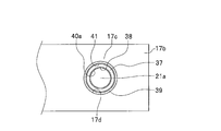
- FIG. 11 is a front view showing a stabilizer link joint structure according to a seventh embodiment of the present invention as seen from the direction of arrow X shown in FIG.
- a through hole 17d is formed in the mounting portion 17c integral with the arm portion 17b of the stabilizer 17.
- the through hole 17d is formed so as to be oriented in a direction perpendicular to the longitudinal direction of the mounting portion 17c.
- a metal cylindrical member 39 is press-fitted and joined to the through hole 17d (details will be described later).
- the outer diameter dimension of the cylindrical member 39 is substantially equal to or slightly smaller than the inner diameter dimension of the through hole 17d.
- the stud portion 21a of the ball stud 21 is elastically joined to the through hole 17d of the mounting portion 17c with a cylindrical elastic member 37 interposed between the stud portion 21a and the cylindrical member 39 inserted through the through hole 17d of the mounting portion 17c. ing.
- the elastic member 37 has a through hole 38 through which the stud portion 21 a of the ball stud 21 is inserted so as to penetrate the cylindrical shaft center portion.
- the inner diameter dimension of the through hole 38 is substantially equal to or slightly larger than the outer diameter dimension of the stud portion 21a.
- the stud portion 21 a of the ball stud 21 is joined to the inner wall of the through hole 38 opened in the elastic member 37.
- This joining is realized by vulcanizing and bonding the inner wall of the through hole 38 to the stud portion 21 a of the ball stud 21.
- This vulcanization adhesion is performed with an adhesive layer 40a (see FIG. 10) having an appropriate thickness interposed.
- the end face of the elastic member 37 on the side facing the disc-shaped flange portion 21a1 provided on the stud portion 21a is vulcanized and bonded to the flange portion 21a1 to reinforce the above-mentioned joining.
- a configuration may be adopted.
- This vulcanization adhesion is also performed with an adhesive layer 40b (see FIG. 10) having an appropriate thickness interposed.
- a cylindrical member 39 is joined to the outer wall of the elastic member 37 as shown in FIGS.
- This joining is realized by vulcanizing and bonding the outer wall of the elastic member 37 to the inner wall of the cylindrical member 39.
- This vulcanization adhesion is performed with an adhesive layer 41 (see FIG. 10) having an appropriate thickness interposed.
- the elastic member 37 is not particularly limited.
- natural rubber epoxidized natural rubber, isoprene rubber, butadiene rubber, butadiene / isoprene rubber, styrene / butadiene rubber, chloroprene rubber, acrylonitrile / butadiene rubber (NBR), hydrogenated nitrile.
- rubber elastic resin such as rubber, chlorinated polyethylene rubber, butyl rubber, acrylic rubber, ethylene / vinyl acetate / acrylic ester copolymer rubber, silicone rubber, styrene / butadiene rubber.
- the thickness dimension of the elastic member 37 may be set to an appropriate dimension through experiments and simulations in consideration of the frequency of vibration that is desired to prevent transmission between the stabilizer link 11 and the stabilizer 17.
- the cylindrical member 39 is joined to the mounting portion 17c integral with the arm portion 17b of the stabilizer 17 by press-fitting the outer wall of the cylindrical member 39 into the inner wall of the through hole 17d provided in the mounting portion 17c. ing.
- the inner wall of the through hole 17d and the outer wall of the cylindrical member 39 may be adhesively bonded using an adhesive.
- a configuration is adopted in which the stabilizer link 11 is elastically joined to the stabilizer 17 by caulking the through-side end portion of the tubular member 39 in a state where the tubular member 39 is passed through the through hole 17d of the mounting portion 17c. Also good.
- the stabilizer link 11 is elastically joined to the stabilizer 17 by welding the through-side end portion of the tubular member 39 to the attachment portion 17c in a state where the tubular member 39 is passed through the through hole 17d of the attachment portion 17c. May be adopted.
- the stud portion 21a of the ball stud 21 is joined to the through hole 17d with the elastic member 37 interposed between the stud portion 21a and the through hole 17d of the mounting portion 17c.
- the cylindrical member 39 is elastically joined.
- vibration and noise can be suppressed and the riding comfort of the vehicle can be satisfactorily maintained.
- the stabilizer link 11 is joined to the stabilizer 17 by press-fitting the stud portion 21a of the ball stud 21 into the through hole 17d of the mounting portion 17c.
- the stud portion 21a of the ball stud 21 is press-fitted into the through hole 17d of the mounting portion 17c, and the stud portion 21a of the ball stud 21 is passed through the through hole 17d of the mounting portion 17c.
- the stabilizer link 11 is joined to the stabilizer 17 by caulking the through-side end 21a2 of the stud portion 21a.
- the stud portion 21a of the ball stud 21 is press-fitted into the through hole 17d of the mounting portion 17c, and the stud portion 21a of the ball stud 21 is passed through the through hole 17d of the mounting portion 17c.
- the stabilizer link 11 is joined to the stabilizer 17 by adhering the outer peripheral wall of the stud portion 21 a to the inner peripheral wall of the through hole 17 d using the adhesive 26.
- the stud portion 21a of the ball stud 21 is press-fitted into the through hole 17d of the mounting portion 17c, and the stud portion 21a of the ball stud 21 is passed through the through hole 17d of the mounting portion 17c.
- the stabilizer link 11 is joined to the stabilizer 17 by welding the through-side end 21a2 of the stud portion 21a to the attachment portion 17c in the state of being made to be.
- the stabilizer is provided by caulking the through-side end portion 21a2 of the stud portion 21a while the stud portion 21a of the ball stud 21 is passed through the through-hole 17d of the mounting portion 17c.
- the link 11 is joined to the stabilizer 17.
- the restraining force on 17c it is possible to realize a firm joint that does not require any special measures against the separation of the stabilizer link 11 from the stabilizer 17.
- the through-side end portion 21a2 of the stud portion 21a is welded to the mounting portion 17c in a state where the stud portion 21a of the ball stud 21 is passed through the through hole 17d of the mounting portion 17c.
- the stabilizer link 11 is joined to the stabilizer 17.
- the mounting portion acting in the axial direction of the stud portion 21a by the cooperation of the welded portions 24-1 to 3 (see FIG. 5A) and the flange portion 21a1 of the stud portion 21a By virtue of the restraining force on 17c, it is possible to realize a firm joint that does not require any special measures against the separation of the stabilizer link 11 from the stabilizer 17.
- the outer peripheral wall of the stud portion 21a is inserted into the through hole 17d in a state where the stud portion 21a of the ball stud 21 is inserted (including through) into the through hole 17d of the mounting portion 17c.
- the stabilizer link 11 is joined to the stabilizer 17 by adhering to the inner peripheral wall using the adhesive 26.
- the stabilizer link 11 is joined to the stabilizer 17 by bonding the outer peripheral wall of the stud portion 21a to the inner peripheral wall of the through hole 17d using the adhesive 26.
- the adhesive 26 it is possible to easily realize a firm joint that does not particularly require a measure for joining the stabilizer link 11 to the stabilizer 17.
- the outer peripheral wall of the stud portion 21a is bonded to the inner peripheral wall of the through hole 17d using the adhesive 26, and the stud of the ball stud 21 is attached to the through hole 17d of the mounting portion 17c.
- the stabilizer link 11 is joined to the stabilizer 17 by caulking the penetrating side end portion 21a2 of the stud portion 21a with the portion 21a being penetrated.
- the outer peripheral wall of the stud portion 21a is bonded to the inner peripheral wall of the through hole 17d using the adhesive 26, and the stud of the ball stud 21 is attached to the through hole 17d of the mounting portion 17c.
- the stabilizer link 11 is joined to the stabilizer 17 by welding the penetration side end portion 21a2 of the stud portion 21a to the attachment portion 17c in a state where the portion 21a is penetrated.
- the receiving grooves 21a3 and 21a4 (see FIGS. 7A and 7B) of the adhesive 26 are provided on the application surface of the adhesive 26 in contact with the through hole 17d in the stud portion 21a. It has been.
- the attachment portions 29 and 33 are separate members from the stabilizer 17 and are joined to both ends of the stabilizer 17, respectively.
- a stabilizer according to the present invention when the stabilizer link 11 is joined to the hollow tubular stabilizer 17, a firm joint that does not particularly require measures for joining the stabilizer link 11 to the stabilizer 17 is required. It can be easily realized.
- the stud portion 21a of the ball stud 21 is joined to the attaching portion 17c by being press-fitted into the through hole 17d of the attaching portion 17c.
- the stabilizer link 11 is prevented from being joined to the stabilizer 17 by the frictional force generated between the outer wall surface of the stud portion 21a and the inner wall surface of the through hole 17d. It is possible to realize a firm joint that is not particularly required.
- the stud portion 21a of the ball stud 21 is attached by caulking the through-side end portion 21a2 of the stud portion 21a in a state of passing through the through hole 17d of the attachment portion 17c. It is joined to the portion 17c.
- the stud portion 21a is attached in the axial direction by the cooperation of the caulking portions 22-1 to 2-3 (see FIG. 3B) and the flange portion 21a1 of the stud portion 21a.
- the portion 17c By the restraining force with respect to the portion 17c, it is possible to realize a firm joint that does not particularly require measures for the joint link 11 to be separated from the stabilizer 17.
- the stud portion 21a of the ball stud 21 welds the through-side end portion 21a2 of the stud portion 21a to the mounting portion 17c while passing through the through hole 17d of the mounting portion 17c. By doing so, it is joined to the mounting portion 17c.
- the attachment that acts in the axial direction of the stud portion 21a by the cooperation of the welded portions 24-1 to 3 (see FIG. 5A) and the flange portion 21a1 of the stud portion 21a.
- the restraining force with respect to the portion 17c it is possible to realize a firm joint that does not particularly require measures for the joint link 11 to be separated from the stabilizer 17.
- the stud portion 21a of the ball stud 21 is inserted into the through hole 17d of the mounting portion 17c (including the through hole), and the stud portion 21a is bonded to the through hole 17d. It is joined to the attachment part 17c by bonding using
- the stud portion 21a is joined to the mounting portion 17c by bonding the outer peripheral wall of the stud portion 21a to the inner peripheral wall of the through hole 17d using the adhesive 26. Therefore, it is possible to easily realize a firm joint that does not particularly require a measure for joining and separating the stabilizer link 11 with respect to the stabilizer 17.
- the stud portion 21a of the ball stud 21 is joined to the through hole 17d with an elastic member 37 interposed between the stud portion 21a and the through hole 17d of the mounting portion 17c. It is elastically joined to the member 39 (that is, the mounting portion 17c).
- the present invention is limited to this example.
- the cylindrical member 39 may be omitted.
- any configuration may be employed as long as the substantially cylindrical elastic member 37 is interposed between the stud portion 21a of the ball stud 21 and the through hole 17d of the mounting portion 17c. Absent.
Landscapes
- Engineering & Computer Science (AREA)
- Mechanical Engineering (AREA)
- General Engineering & Computer Science (AREA)
- Vehicle Body Suspensions (AREA)
- Pivots And Pivotal Connections (AREA)
Abstract
Priority Applications (8)
| Application Number | Priority Date | Filing Date | Title |
|---|---|---|---|
| KR1020197007498A KR20190038916A (ko) | 2016-09-05 | 2017-08-23 | 스태빌라이저의 제조 방법, 및 스태빌라이저 링크의 접합 구조 |
| MX2019002539A MX2019002539A (es) | 2016-09-05 | 2017-08-23 | Metodo de manufactura del estabilizador, y estructura de la junta o union del enlace del estabilizador. |
| CA3035885A CA3035885A1 (fr) | 2016-09-05 | 2017-08-23 | Procede de fabrication de stabilisateur et structure de joint pour liaison de stabilisateur |
| CN201780052468.7A CN109641502A (zh) | 2016-09-05 | 2017-08-23 | 稳定器的制造方法及稳定器连杆的接合构造 |
| JP2018537183A JPWO2018043248A1 (ja) | 2016-09-05 | 2017-08-23 | スタビライザの製造方法、及びスタビリンクの接合構造 |
| US16/330,590 US20210276390A1 (en) | 2016-09-05 | 2017-08-23 | Stabilizer manufacturing method, and joint structure for stabilizer link |
| BR112019002658A BR112019002658A2 (pt) | 2016-09-05 | 2017-08-23 | método de fabricação de estabilizadores e estrutura de junta para bieleta |
| EP17846253.7A EP3508362A4 (fr) | 2016-09-05 | 2017-08-23 | Procédé de fabrication de stabilisateur et structure de joint pour liaison de stabilisateur |
Applications Claiming Priority (4)
| Application Number | Priority Date | Filing Date | Title |
|---|---|---|---|
| JP2016172572 | 2016-09-05 | ||
| JP2016-172572 | 2016-09-05 | ||
| JP2017-109235 | 2017-06-01 | ||
| JP2017109235 | 2017-06-01 |
Publications (1)
| Publication Number | Publication Date |
|---|---|
| WO2018043248A1 true WO2018043248A1 (fr) | 2018-03-08 |
Family
ID=61300693
Family Applications (1)
| Application Number | Title | Priority Date | Filing Date |
|---|---|---|---|
| PCT/JP2017/030140 Ceased WO2018043248A1 (fr) | 2016-09-05 | 2017-08-23 | Procédé de fabrication de stabilisateur et structure de joint pour liaison de stabilisateur |
Country Status (9)
| Country | Link |
|---|---|
| US (1) | US20210276390A1 (fr) |
| EP (1) | EP3508362A4 (fr) |
| JP (1) | JPWO2018043248A1 (fr) |
| KR (1) | KR20190038916A (fr) |
| CN (1) | CN109641502A (fr) |
| BR (1) | BR112019002658A2 (fr) |
| CA (1) | CA3035885A1 (fr) |
| MX (1) | MX2019002539A (fr) |
| WO (1) | WO2018043248A1 (fr) |
Cited By (3)
| Publication number | Priority date | Publication date | Assignee | Title |
|---|---|---|---|---|
| KR102344702B1 (ko) * | 2021-07-05 | 2021-12-30 | 김원홍 | 승용차용 서스펜션에 장착되는 이너 튜브의 제조 방법 |
| US11376919B2 (en) * | 2020-05-06 | 2022-07-05 | Zf Friedrichshafen Ag | Chassis component and stabilizer arrangement for a chassis of a vehicle with such a chassis component |
| US20220363103A1 (en) * | 2019-07-02 | 2022-11-17 | Nhk Spring Co., Ltd. | Stabilizer |
Citations (11)
| Publication number | Priority date | Publication date | Assignee | Title |
|---|---|---|---|---|
| JPS49121668U (fr) * | 1973-02-14 | 1974-10-18 | ||
| JPH0652857U (ja) * | 1992-12-28 | 1994-07-19 | ヤマハ株式会社 | ゴルフ用クラブ |
| JP2000320529A (ja) * | 1999-05-13 | 2000-11-24 | Tokai Rubber Ind Ltd | プロペラシャフト |
| JP2001055035A (ja) * | 1999-07-01 | 2001-02-27 | American Accel & Manufacturing Inc | プラグイン型直動スタビライザバーリンク |
| JP2002227828A (ja) * | 2001-02-02 | 2002-08-14 | Honda Motor Co Ltd | ボールスタッド及びレバー部材の結合方法 |
| JP2002256828A (ja) * | 2001-03-05 | 2002-09-11 | Mitsubishi Electric Corp | バルブタイミング調整装置 |
| JP2002333010A (ja) * | 2001-05-08 | 2002-11-22 | Nissan Motor Co Ltd | ボールジョイントの取付け構造 |
| JP2007192326A (ja) * | 2006-01-19 | 2007-08-02 | Gkn ドライブライン トルクテクノロジー株式会社 | 動力伝達装置 |
| JP2009031745A (ja) * | 2007-07-04 | 2009-02-12 | 21:Kk | リムレス眼鏡 |
| JP2015151097A (ja) * | 2014-02-18 | 2015-08-24 | 日本発條株式会社 | リンクアーム部材、及び、リンクアーム部材の製造方法 |
| JP2016084057A (ja) | 2014-10-28 | 2016-05-19 | 日本発條株式会社 | リンクアーム部材 |
Family Cites Families (10)
| Publication number | Priority date | Publication date | Assignee | Title |
|---|---|---|---|---|
| US3679248A (en) * | 1971-08-05 | 1972-07-25 | Trw Inc | Ball joint |
| JPH0542049U (ja) * | 1991-11-12 | 1993-06-08 | 株式会社リズム | タイロツド |
| US6076840A (en) * | 1998-05-19 | 2000-06-20 | American Axle & Manufacturing, Inc. | Self-locking plug-in stabilizer bar links |
| KR20030082271A (ko) * | 2002-04-17 | 2003-10-22 | 기아자동차주식회사 | 피트먼 암 체결구조 |
| JP2004251410A (ja) * | 2003-02-21 | 2004-09-09 | Nippon Thompson Co Ltd | 軸継ぎ手 |
| KR20080109972A (ko) * | 2007-06-14 | 2008-12-18 | 현대자동차주식회사 | 자동차용 스테빌라이저 |
| KR20130056642A (ko) * | 2011-11-22 | 2013-05-30 | 현대자동차주식회사 | 스테빌라이져 바 링크의 가변조절장치 |
| JP5476402B2 (ja) * | 2012-02-16 | 2014-04-23 | 日本発條株式会社 | スタビリンクおよびその製造方法 |
| DE102014110139A1 (de) * | 2014-05-27 | 2015-12-03 | Heiko Schmidt | Verfahren zur Herstellung einer Nietverbindung zwischen einem Kugelgelenkbolzen und einem blechförmigen Bauteil sowie zugehörige vorgefertigte Baugruppe |
| CN204383117U (zh) * | 2014-11-25 | 2015-06-10 | 广汽吉奥汽车有限公司 | 一种多用途汽车及其横向稳定杆连接杆组件 |
-
2017
- 2017-08-23 MX MX2019002539A patent/MX2019002539A/es unknown
- 2017-08-23 WO PCT/JP2017/030140 patent/WO2018043248A1/fr not_active Ceased
- 2017-08-23 BR BR112019002658A patent/BR112019002658A2/pt not_active Application Discontinuation
- 2017-08-23 CA CA3035885A patent/CA3035885A1/fr not_active Abandoned
- 2017-08-23 EP EP17846253.7A patent/EP3508362A4/fr not_active Withdrawn
- 2017-08-23 JP JP2018537183A patent/JPWO2018043248A1/ja active Pending
- 2017-08-23 US US16/330,590 patent/US20210276390A1/en not_active Abandoned
- 2017-08-23 KR KR1020197007498A patent/KR20190038916A/ko not_active Abandoned
- 2017-08-23 CN CN201780052468.7A patent/CN109641502A/zh active Pending
Patent Citations (11)
| Publication number | Priority date | Publication date | Assignee | Title |
|---|---|---|---|---|
| JPS49121668U (fr) * | 1973-02-14 | 1974-10-18 | ||
| JPH0652857U (ja) * | 1992-12-28 | 1994-07-19 | ヤマハ株式会社 | ゴルフ用クラブ |
| JP2000320529A (ja) * | 1999-05-13 | 2000-11-24 | Tokai Rubber Ind Ltd | プロペラシャフト |
| JP2001055035A (ja) * | 1999-07-01 | 2001-02-27 | American Accel & Manufacturing Inc | プラグイン型直動スタビライザバーリンク |
| JP2002227828A (ja) * | 2001-02-02 | 2002-08-14 | Honda Motor Co Ltd | ボールスタッド及びレバー部材の結合方法 |
| JP2002256828A (ja) * | 2001-03-05 | 2002-09-11 | Mitsubishi Electric Corp | バルブタイミング調整装置 |
| JP2002333010A (ja) * | 2001-05-08 | 2002-11-22 | Nissan Motor Co Ltd | ボールジョイントの取付け構造 |
| JP2007192326A (ja) * | 2006-01-19 | 2007-08-02 | Gkn ドライブライン トルクテクノロジー株式会社 | 動力伝達装置 |
| JP2009031745A (ja) * | 2007-07-04 | 2009-02-12 | 21:Kk | リムレス眼鏡 |
| JP2015151097A (ja) * | 2014-02-18 | 2015-08-24 | 日本発條株式会社 | リンクアーム部材、及び、リンクアーム部材の製造方法 |
| JP2016084057A (ja) | 2014-10-28 | 2016-05-19 | 日本発條株式会社 | リンクアーム部材 |
Non-Patent Citations (1)
| Title |
|---|
| See also references of EP3508362A4 |
Cited By (4)
| Publication number | Priority date | Publication date | Assignee | Title |
|---|---|---|---|---|
| US20220363103A1 (en) * | 2019-07-02 | 2022-11-17 | Nhk Spring Co., Ltd. | Stabilizer |
| US11820192B2 (en) * | 2019-07-02 | 2023-11-21 | Nhk Spring Co., Ltd. | Stabilizer |
| US11376919B2 (en) * | 2020-05-06 | 2022-07-05 | Zf Friedrichshafen Ag | Chassis component and stabilizer arrangement for a chassis of a vehicle with such a chassis component |
| KR102344702B1 (ko) * | 2021-07-05 | 2021-12-30 | 김원홍 | 승용차용 서스펜션에 장착되는 이너 튜브의 제조 방법 |
Also Published As
| Publication number | Publication date |
|---|---|
| EP3508362A4 (fr) | 2020-05-06 |
| MX2019002539A (es) | 2019-07-15 |
| BR112019002658A2 (pt) | 2019-05-28 |
| KR20190038916A (ko) | 2019-04-09 |
| CA3035885A1 (fr) | 2018-03-08 |
| US20210276390A1 (en) | 2021-09-09 |
| EP3508362A1 (fr) | 2019-07-10 |
| JPWO2018043248A1 (ja) | 2019-06-24 |
| CN109641502A (zh) | 2019-04-16 |
Similar Documents
| Publication | Publication Date | Title |
|---|---|---|
| KR102714870B1 (ko) | 튜닝 자유도 개선형 부시 및 현가 시스템 | |
| JP6909815B2 (ja) | 車両骨格サポート装置 | |
| WO2018043248A1 (fr) | Procédé de fabrication de stabilisateur et structure de joint pour liaison de stabilisateur | |
| JP6431380B2 (ja) | 防振装置 | |
| JP6494321B2 (ja) | 防振装置用ブラケットとブラケット付防振装置、防振装置用ブラケットの製造方法 | |
| JP2018090245A (ja) | 車両のサスペンションのためのスタビライザー | |
| EP3632717B1 (fr) | Structure de charnière de liaison de stabilisation | |
| KR101450319B1 (ko) | 조향장치 기어 하우징의 마운팅 부시 | |
| JP5119863B2 (ja) | ピロボール構造及びサスペンション構造 | |
| JP2016161102A (ja) | ストラット式サスペンション装置 | |
| KR20180076239A (ko) | 리벳 및 이를 이용한 판재의 접합방법 | |
| JP2013224106A (ja) | ステアリング装置 | |
| JP2008106867A (ja) | ストラットマウント | |
| JP2010126139A (ja) | サスペンションアーム締結構造 | |
| WO2016113996A1 (fr) | Amortisseur de chocs | |
| KR101450323B1 (ko) | 조향장치 기어 하우징의 마운팅 부시 | |
| KR20240166786A (ko) | 스태빌라이저바 링크 | |
| KR102552072B1 (ko) | 내측고정방식 마운팅 부시 유닛 및 서브프레임 | |
| KR20250052603A (ko) | 샤프트 요크 핀 압입 결합구조 | |
| KR102474602B1 (ko) | 강체 압입방식 인슐레이터 및 현가 시스템 | |
| JP2016175535A (ja) | ステアリング装置 | |
| JP2015047996A (ja) | 車両用サスペンションアーム | |
| JP2018090087A (ja) | ステアリング装置 | |
| JP2019100471A (ja) | 防振装置及び防振構造 | |
| JP2016130537A (ja) | 防振装置 |
Legal Events
| Date | Code | Title | Description |
|---|---|---|---|
| 121 | Ep: the epo has been informed by wipo that ep was designated in this application |
Ref document number: 17846253 Country of ref document: EP Kind code of ref document: A1 |
|
| ENP | Entry into the national phase |
Ref document number: 2018537183 Country of ref document: JP Kind code of ref document: A |
|
| ENP | Entry into the national phase |
Ref document number: 3035885 Country of ref document: CA |
|
| NENP | Non-entry into the national phase |
Ref country code: DE |
|
| ENP | Entry into the national phase |
Ref document number: 20197007498 Country of ref document: KR Kind code of ref document: A |
|
| REG | Reference to national code |
Ref country code: BR Ref legal event code: B01A Ref document number: 112019002658 Country of ref document: BR |
|
| ENP | Entry into the national phase |
Ref document number: 2017846253 Country of ref document: EP Effective date: 20190405 |
|
| ENP | Entry into the national phase |
Ref document number: 112019002658 Country of ref document: BR Kind code of ref document: A2 Effective date: 20190208 |