WO2018043293A1 - Endoscope électronique et système d'endoscope électronique - Google Patents
Endoscope électronique et système d'endoscope électronique Download PDFInfo
- Publication number
- WO2018043293A1 WO2018043293A1 PCT/JP2017/030383 JP2017030383W WO2018043293A1 WO 2018043293 A1 WO2018043293 A1 WO 2018043293A1 JP 2017030383 W JP2017030383 W JP 2017030383W WO 2018043293 A1 WO2018043293 A1 WO 2018043293A1
- Authority
- WO
- WIPO (PCT)
- Prior art keywords
- light
- light source
- wavelength
- electronic
- source device
- Prior art date
- Legal status (The legal status is an assumption and is not a legal conclusion. Google has not performed a legal analysis and makes no representation as to the accuracy of the status listed.)
- Ceased
Links
Images


Classifications
-
- A—HUMAN NECESSITIES
- A61—MEDICAL OR VETERINARY SCIENCE; HYGIENE
- A61B—DIAGNOSIS; SURGERY; IDENTIFICATION
- A61B1/00—Instruments for performing medical examinations of the interior of cavities or tubes of the body by visual or photographical inspection, e.g. endoscopes; Illuminating arrangements therefor
- A61B1/06—Instruments for performing medical examinations of the interior of cavities or tubes of the body by visual or photographical inspection, e.g. endoscopes; Illuminating arrangements therefor with illuminating arrangements
- A61B1/07—Instruments for performing medical examinations of the interior of cavities or tubes of the body by visual or photographical inspection, e.g. endoscopes; Illuminating arrangements therefor with illuminating arrangements using light-conductive means, e.g. optical fibres
-
- A—HUMAN NECESSITIES
- A61—MEDICAL OR VETERINARY SCIENCE; HYGIENE
- A61B—DIAGNOSIS; SURGERY; IDENTIFICATION
- A61B1/00—Instruments for performing medical examinations of the interior of cavities or tubes of the body by visual or photographical inspection, e.g. endoscopes; Illuminating arrangements therefor
- A61B1/00002—Operational features of endoscopes
- A61B1/00004—Operational features of endoscopes characterised by electronic signal processing
- A61B1/00006—Operational features of endoscopes characterised by electronic signal processing of control signals
-
- A—HUMAN NECESSITIES
- A61—MEDICAL OR VETERINARY SCIENCE; HYGIENE
- A61B—DIAGNOSIS; SURGERY; IDENTIFICATION
- A61B1/00—Instruments for performing medical examinations of the interior of cavities or tubes of the body by visual or photographical inspection, e.g. endoscopes; Illuminating arrangements therefor
- A61B1/04—Instruments for performing medical examinations of the interior of cavities or tubes of the body by visual or photographical inspection, e.g. endoscopes; Illuminating arrangements therefor combined with photographic or television appliances
- A61B1/043—Instruments for performing medical examinations of the interior of cavities or tubes of the body by visual or photographical inspection, e.g. endoscopes; Illuminating arrangements therefor combined with photographic or television appliances for fluorescence imaging
-
- A—HUMAN NECESSITIES
- A61—MEDICAL OR VETERINARY SCIENCE; HYGIENE
- A61B—DIAGNOSIS; SURGERY; IDENTIFICATION
- A61B1/00—Instruments for performing medical examinations of the interior of cavities or tubes of the body by visual or photographical inspection, e.g. endoscopes; Illuminating arrangements therefor
- A61B1/06—Instruments for performing medical examinations of the interior of cavities or tubes of the body by visual or photographical inspection, e.g. endoscopes; Illuminating arrangements therefor with illuminating arrangements
- A61B1/0638—Instruments for performing medical examinations of the interior of cavities or tubes of the body by visual or photographical inspection, e.g. endoscopes; Illuminating arrangements therefor with illuminating arrangements providing two or more wavelengths
-
- A—HUMAN NECESSITIES
- A61—MEDICAL OR VETERINARY SCIENCE; HYGIENE
- A61B—DIAGNOSIS; SURGERY; IDENTIFICATION
- A61B1/00—Instruments for performing medical examinations of the interior of cavities or tubes of the body by visual or photographical inspection, e.g. endoscopes; Illuminating arrangements therefor
- A61B1/06—Instruments for performing medical examinations of the interior of cavities or tubes of the body by visual or photographical inspection, e.g. endoscopes; Illuminating arrangements therefor with illuminating arrangements
- A61B1/0646—Instruments for performing medical examinations of the interior of cavities or tubes of the body by visual or photographical inspection, e.g. endoscopes; Illuminating arrangements therefor with illuminating arrangements with illumination filters
-
- A—HUMAN NECESSITIES
- A61—MEDICAL OR VETERINARY SCIENCE; HYGIENE
- A61B—DIAGNOSIS; SURGERY; IDENTIFICATION
- A61B1/00—Instruments for performing medical examinations of the interior of cavities or tubes of the body by visual or photographical inspection, e.g. endoscopes; Illuminating arrangements therefor
- A61B1/06—Instruments for performing medical examinations of the interior of cavities or tubes of the body by visual or photographical inspection, e.g. endoscopes; Illuminating arrangements therefor with illuminating arrangements
- A61B1/0653—Instruments for performing medical examinations of the interior of cavities or tubes of the body by visual or photographical inspection, e.g. endoscopes; Illuminating arrangements therefor with illuminating arrangements with wavelength conversion
-
- A—HUMAN NECESSITIES
- A61—MEDICAL OR VETERINARY SCIENCE; HYGIENE
- A61B—DIAGNOSIS; SURGERY; IDENTIFICATION
- A61B1/00—Instruments for performing medical examinations of the interior of cavities or tubes of the body by visual or photographical inspection, e.g. endoscopes; Illuminating arrangements therefor
- A61B1/06—Instruments for performing medical examinations of the interior of cavities or tubes of the body by visual or photographical inspection, e.g. endoscopes; Illuminating arrangements therefor with illuminating arrangements
- A61B1/0655—Control therefor
-
- A—HUMAN NECESSITIES
- A61—MEDICAL OR VETERINARY SCIENCE; HYGIENE
- A61B—DIAGNOSIS; SURGERY; IDENTIFICATION
- A61B1/00—Instruments for performing medical examinations of the interior of cavities or tubes of the body by visual or photographical inspection, e.g. endoscopes; Illuminating arrangements therefor
- A61B1/06—Instruments for performing medical examinations of the interior of cavities or tubes of the body by visual or photographical inspection, e.g. endoscopes; Illuminating arrangements therefor with illuminating arrangements
- A61B1/0661—Endoscope light sources
- A61B1/0669—Endoscope light sources at proximal end of an endoscope
-
- A—HUMAN NECESSITIES
- A61—MEDICAL OR VETERINARY SCIENCE; HYGIENE
- A61B—DIAGNOSIS; SURGERY; IDENTIFICATION
- A61B1/00—Instruments for performing medical examinations of the interior of cavities or tubes of the body by visual or photographical inspection, e.g. endoscopes; Illuminating arrangements therefor
- A61B1/06—Instruments for performing medical examinations of the interior of cavities or tubes of the body by visual or photographical inspection, e.g. endoscopes; Illuminating arrangements therefor with illuminating arrangements
- A61B1/0661—Endoscope light sources
- A61B1/0684—Endoscope light sources using light emitting diodes [LED]
-
- G—PHYSICS
- G02—OPTICS
- G02B—OPTICAL ELEMENTS, SYSTEMS OR APPARATUS
- G02B23/00—Telescopes, e.g. binoculars; Periscopes; Instruments for viewing the inside of hollow bodies; Viewfinders; Optical aiming or sighting devices
- G02B23/24—Instruments or systems for viewing the inside of hollow bodies, e.g. fibrescopes
- G02B23/2407—Optical details
- G02B23/2461—Illumination
- G02B23/2469—Illumination using optical fibres
-
- G—PHYSICS
- G02—OPTICS
- G02B—OPTICAL ELEMENTS, SYSTEMS OR APPARATUS
- G02B23/00—Telescopes, e.g. binoculars; Periscopes; Instruments for viewing the inside of hollow bodies; Viewfinders; Optical aiming or sighting devices
- G02B23/24—Instruments or systems for viewing the inside of hollow bodies, e.g. fibrescopes
- G02B23/26—Instruments or systems for viewing the inside of hollow bodies, e.g. fibrescopes using light guides
Definitions
- the present invention relates to an electronic scope and an electronic endoscope system.
- Patent Document 1 describes a specific configuration of a light source device used in this type of endoscope system.
- the endoscope system described in Patent Document 1 includes a light source device on which two light emitting diodes (LEDs) are mounted and an optical filter.
- One of the two LEDs is a purple LED that emits light in a purple wavelength band.
- the other LED is a phosphor LED having a blue LED and a yellow phosphor. By mixing blue LED light and yellow fluorescence, pseudo white light is emitted.
- the optical filter is a wavelength selection filter that allows only light in a specific wavelength range to pass through, and is disposed so as to be insertable / removable on the optical path of irradiation light emitted from the phosphor LED.
- the light source device described in Patent Document 1 when the optical filter is extracted from the optical path, the light emitted from the phosphor LED is irradiated to the subject as white light without limiting the wavelength band.
- the optical filter when the optical filter is inserted on the optical path, the subject is irradiated with both the irradiation light emitted from the phosphor LED and the wavelength band limited and the irradiation light emitted from the purple LED.
- the spectral intensity characteristic of the irradiation light and irradiating the subject with only light in a specific wavelength band, it is possible to obtain a captured image in which a specific tissue is emphasized among subjects in the living body.
- the optical fiber has a characteristic of transmitting light in the visible light band.
- the optical fiber has a wavelength dependency of transmittance depending on the material. For example, quartz generally used for optical fibers has a lower transmittance as the wavelength of light becomes shorter. Therefore, when the subject is observed using purple light having a relatively short wavelength, there is a problem that the amount of the purple light is small and the obtained captured image becomes dark. In addition, the optical fiber may be yellowed due to the material used and deterioration with time.
- the present invention provides an electronic scope and an electronic endoscope that can prevent a decrease in the amount of light in a desired wavelength band even if the light transmittance of the optical fiber has different characteristics in the wavelength band. It is to provide a mirror system.
- an electronic scope includes: An insertion tube configured to be inserted into a body cavity and having a light exit at the tip; A light guide configured to guide the first light from the distal end to the distal end of the insertion tube; A light emitting element configured to emit from the tip portion second light in a wavelength band in which the light transmittance in the light guide is equal to or lower than the transmittance in the wavelength band of the first light.
- the optical path length of the second light from the light emitting element to the second light exit provided at the tip is shorter than the optical path length of the first light in the light guide.
- the light emitting element is preferably provided at the tip.
- the second light has a peak wavelength between a wavelength of 405 nm and a wavelength of 425 nm.
- a plurality of solid state light emitting elements are provided at the tip, and the light emitting element is one of the solid state light emitting elements.
- the electronic scope includes a light source device configured to emit the first light to the light guide.
- An electronic endoscope system includes: The electronic scope; An electronic endoscope processor capable of detachably connecting the electronic scope; Is provided.
- the electronic endoscope processor includes: The light source device configured to emit the first light; and A light source driving circuit configured to generate a control signal for controlling light emission of the light emitting element and the light source device; Is provided.
- the electronic endoscope processor has an optical filter that can be inserted into and removed from the optical path of the first light.
- the optical filter has a filter characteristic that transmits only light in a green wavelength band in a visible light band.
- An electronic endoscope system includes: The electronic scope; A light source device configured to emit the first light to the light guide.
- the first light includes light having a longer wavelength than the second light.
- the light source device preferably includes a plurality of light source units configured to emit light having different wavelength bands.
- one of the plurality of light source units is a light source unit configured to emit the second light.
- the electronic endoscope system is configured to generate a control signal for individually controlling light emission of the light emitting element and the light source device according to each of a plurality of modes.
- the light source driving circuit generates at least a first control signal for driving the light source device to emit light in the first mode, and generates a second control signal for driving at least the light emitting element to emit light in the second mode, It is preferable that the light source device and the light emitting element are configured to be controlled.
- the electronic endoscope system includes a light source driving circuit configured to generate a control signal for individually controlling light emission of the solid state light emitting element and the light source device,
- the electronic scope includes an imaging device configured to capture an image of a subject at a predetermined frame period and generate an image signal;
- the light source driving circuit is configured to alternately generate at least a first control signal for driving light emission of the light source device and a second control signal for driving light emission of at least the light emitting element for each frame of the image signal. It is preferable that
- FIG. 1 is a block diagram of an electronic endoscope system according to an embodiment of the present invention. It is a block diagram of the light source device which concerns on the 1st Embodiment of this invention.
- (A), (b) is a figure which shows the spectral intensity distribution of the illumination light based on the 1st Embodiment of this invention. It is a block diagram of the light source device which concerns on the 2nd Embodiment of this invention.
- (A), (b) is a figure which shows the spectral intensity distribution of the illumination light based on the 2nd Embodiment of this invention. It is a block diagram of the light source device which concerns on the 3rd Embodiment of this invention.
- (A), (b) is a figure which shows the spectral intensity distribution of the illumination light based on the 3rd Embodiment of this invention.
- An electronic scope includes: An insertion tube configured to be inserted into a body cavity and having a light exit at the tip; A light guide configured to guide the first light from the distal end to the distal end of the insertion tube; A light emitting device configured to emit from the tip portion second light in a wavelength band in which the light transmittance in the light guide is equal to or lower than the transmittance in the wavelength band of the first light; Is provided.
- the optical path length of the second light from the light emitting element to the second light exit port provided at the tip is shorter than the optical path length of the first light in the light guide that guides the first light.
- the light path length of the second light whose light transmittance in the light guide is equal to or less than the transmittance of the wavelength band of the first light is shorter than the light path length of the ride guide that guides the first light.
- the light emitting element is preferably provided at the tip of the electronic scope. This eliminates the need to guide the second light by the light guide, so that there is no light loss of the second light by the light guide.
- the second light may be emitted from the outlet of the distal end portion using light guide by a ride guide cable. Even in this case, since the length of the light guide cable that guides the second light is short, the light loss due to the light guide of the second light is smaller than when the light guide cable is guided by the same light guide cable as the first light. It is suppressed.
- the light emitting element is preferably configured to emit second light whose light transmittance in the light guide is lower than the transmittance in the wavelength band of the first light.
- FIG. 1 is a block diagram showing a configuration of an electronic endoscope system 1 including an endoscope light source device 201 according to the first embodiment of the present invention.
- the electronic endoscope system 1 is a system specialized for medical use, and includes an electronic scope 100, a processor 200, and a monitor 300.
- the electronic scope 100 includes an insertion tube 101 to be inserted into a human body cavity and a connection portion 102.
- the electronic scope 100 is detachably connected to the processor 200 via the connection unit 102.
- the processor 200 includes a system controller 21 and a timing controller 22.
- the system controller 21 executes various programs stored in the memory 23 and controls the entire electronic endoscope system 1 in an integrated manner.
- the system controller 21 is connected to the operation panel 24.
- the system controller 21 changes each operation of the electronic endoscope system 1 and parameters for each operation in accordance with an instruction from the operator input to the operation panel 24.
- the timing controller 22 outputs a clock pulse for adjusting the operation timing of each unit to each circuit in the electronic endoscope system 1.
- the processor 200 includes a light source device 201.
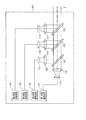
- FIG. 2 shows a block diagram of the light source device 201.
- the light source device 201 includes first to fourth light source units 111 to 114.
- the first to fourth light source units 111 to 114 are individually controlled to emit light by control signals generated by the first to fourth light source drive circuits 141 to 144, respectively.
- the first light source unit 111 is a red LED (Light Emitting Diode) that emits light in a red wavelength band (for example, a wavelength of 620 to 680 nm).
- the second light source unit 112 includes a blue LED that emits light in a blue wavelength band (for example, a wavelength of 430 to 470 nm) and a phosphor. The phosphor is excited by blue LED light emitted from the blue LED, and emits fluorescence in a green wavelength band (for example, a wavelength of 460 to 600 nm).
- the third light source unit 113 is a blue LED that emits light in a blue wavelength band (for example, a wavelength of 430 to 470 nm).
- the fourth light source unit 114 is a purple LED that emits light in a purple wavelength band (for example, a wavelength of 395 to 435 nm).
- Collimating lenses 121 to 124 are arranged in front of the light source units 111 to 114 in the light emission direction, respectively.
- the red LED light emitted from the first light source unit 111 is converted into parallel light by the collimator lens 121 and is incident on the dichroic mirror 131.
- the light emitted from the second light source unit 112, that is, the blue LED light and the green fluorescence is converted into parallel light by the collimator lens 122 and is incident on the dichroic mirror 131.
- the dichroic mirror 131 combines the optical path of the light emitted from the first light source unit 111 and the optical path of the light emitted from the second light source unit 112.
- the dichroic mirror 131 has a cutoff wavelength in the vicinity of a wavelength of 600 nm, has a characteristic of transmitting light having a wavelength longer than the cutoff wavelength, and reflecting light having a wavelength shorter than the cutoff wavelength. Yes. Therefore, the red LED light emitted from the first light source unit 111 passes through the dichroic mirror 131, and the light emitted from the second light source unit 112 is reflected by the dichroic mirror 131. Thereby, the optical path of red LED light, the optical path of blue LED light, and green fluorescence are combined. The light whose optical path is synthesized by the dichroic mirror 131 is incident on the dichroic mirror 132.
- the blue LED light emitted from the third light source unit 113 is converted into parallel light by the collimator lens 123 and is incident on the dichroic mirror 132.
- the dichroic mirror 132 combines the optical path of the light incident from the dichroic mirror 131 and the optical path of the blue LED light emitted from the third light source unit 113.
- the dichroic mirror 132 has a cutoff wavelength in the vicinity of a wavelength of 500 nm, transmits light having a wavelength longer than the cutoff wavelength, and reflects light having a wavelength shorter than the cutoff wavelength. Yes.
- red LED light and green fluorescence pass through the dichroic mirror 132, and blue LED light is reflected by the dichroic mirror 132.
- the blue LED emitted from the third light source unit 113 is reflected by the dichroic mirror 132.
- the optical path of the red LED light and the green fluorescence and the optical path of the blue LED emitted from the third light source unit 113 are combined.
- the light whose optical path is synthesized by the dichroic mirror 132 is incident on the dichroic mirror 133.
- the purple LED light emitted from the fourth light source unit 114 is converted into parallel light by the collimator lens 124 and is incident on the dichroic mirror 133.
- the dichroic mirror 133 combines the optical path of the light incident from the dichroic mirror 132 and the optical path of the purple LED light emitted from the fourth light source unit 114.
- the dichroic mirror 133 has a cutoff wavelength near a wavelength of 430 nm, has a characteristic of transmitting light having a wavelength longer than the cutoff wavelength, and reflecting light having a wavelength shorter than the cutoff wavelength. Yes. Therefore, the light incident from the dichroic mirror 132 and the purple LED light emitted from the fourth light source unit 114 are combined by the dichroic mirror 133 and emitted from the light source device 201 as illumination light L.
- the illumination light L emitted from the light source device 201 is condensed on the incident end face of the LCB (Light Carrying Bundle) 11 by the condenser lens 25 and is incident on the LCB 11.
- LCB Light Carrying Bundle
- the illumination light L incident on the LCB 11 propagates in the LCB 11.
- the illumination light L propagating through the LCB 11 is emitted from the exit end face of the LCB 11 disposed at the distal end portion 101A of the electronic scope 100, and is irradiated onto the subject via the light distribution lens 12 provided at the exit port 101B.
- the return light from the subject illuminated by the illumination light L from the light distribution lens 12 forms an optical image on the light receiving surface of the solid-state imaging device 14 via the objective lens 13.
- the solid-state imaging device 14 is a single-plate color CCD (Charge Coupled Device) image sensor having a Bayer pixel arrangement.
- the solid-state imaging device 14 accumulates an optical image formed by each pixel on the light receiving surface as a charge corresponding to the amount of light, and generates R (Red), G (Green), and B (Blue) image signals. Output.
- the solid-state imaging device 14 is not limited to a CCD image sensor, and may be replaced with a CMOS (Complementary Metal Oxide Semiconductor) image sensor or other types of imaging devices.
- the solid-state image sensor 14 may also be one having a complementary color filter mounted thereon.
- a driver signal processing circuit 15 is provided in the connection part 102 of the electronic scope 100.
- the driver signal processing circuit 15 receives an image signal of a subject from the solid-state imaging device 14 at a predetermined frame period.
- the frame period is, for example, 1/30 seconds.
- the driver signal processing circuit 15 performs a predetermined process on the image signal input from the solid-state imaging device 14 and outputs the processed image signal to the upstream signal processing circuit 26 of the processor 200.
- the driver signal processing circuit 15 also accesses the memory 16 and reads the unique information of the electronic scope 100.
- the unique information of the electronic scope 100 recorded in the memory 16 includes, for example, the number of pixels and sensitivity of the solid-state imaging device 14, an operable frame period, a model number, and the like.
- the driver signal processing circuit 15 outputs the unique information read from the memory 16 to the system controller 21.
- the system controller 21 performs various calculations based on the unique information of the electronic scope 100 and generates a control signal.
- the system controller 21 uses the generated control signal to control the operation and timing of various circuits in the processor 200 so that processing suitable for the electronic scope 100 connected to the processor 200 is performed.
- the timing controller 22 supplies clock pulses to the driver signal processing circuit 15 according to the timing control by the system controller 21.
- the driver signal processing circuit 15 drives and controls the solid-state imaging device 14 at a timing synchronized with the frame period of the video processed on the processor 200 side, according to the clock pulse supplied from the timing controller 22.
- the pre-stage signal processing circuit 26 performs predetermined signal processing such as demosaic processing, matrix calculation, and Y / C separation on the image signal input from the driver signal processing circuit 15 in one frame period, and outputs it to the image memory 27. To do.
- the image memory 27 buffers the image signal input from the upstream signal processing circuit 26 and outputs it to the downstream signal processing circuit 28 according to the timing control by the timing controller 22.
- the post-stage signal processing circuit 28 processes the image signal input from the image memory 27 to generate screen data for monitor display, and converts the generated screen data for monitor display into a predetermined video format signal.
- the converted video format signal is output to the monitor 300. Thereby, the image of the subject is displayed on the display screen of the monitor 300.
- an LED 18 (light emitting element or solid light emitting element) is disposed at the distal end 101A of the insertion tube 101 of the electronic scope 100.
- the light emission of the LED 18 is controlled by a control signal generated by the light source driving circuit 17 provided in the connection unit 102.
- the LED 18 is a purple LED that emits light in a purple wavelength band (for example, a wavelength of 395 to 435 nm).
- the purple LED light emitted from the LED 18 is irradiated to the subject via the light distribution lens 19 provided at the exit port 101C.
- the reason why the LED 18 is provided at the distal end portion 101A is that the light emitted from the LED 108 (second light) is not guided by the LCB 11 that absorbs part of the light.
- the LCB 11 has transmission characteristics with different transmittances depending on the wavelength band of light. For this reason, LED18 inject
- the light emitted from the LED 18 is light in a purple wavelength band.
- the electronic endoscope system 1 has a plurality of observation modes including a normal observation mode and a special observation mode.
- Each observation mode is switched manually or automatically depending on the subject to be observed. For example, when it is desired to observe the subject illuminated with normal light, the observation mode is switched to the normal observation mode.
- the normal light is, for example, white light or pseudo white light.
- White light has a flat spectral intensity distribution in the visible light band.
- the pseudo-white light has a spectral intensity distribution that is not flat, and light in a plurality of wavelength bands is mixed.
- the observation mode is switched to the special observation mode.
- the special light is, for example, light having a high absorbance with respect to a specific living tissue.
- the biological tissue emphasized in the special observation mode is a surface blood vessel will be described.
- the superficial blood vessel contains blood having hemoglobin therein. It is known that hemoglobin has absorbance peaks near wavelengths of 415 nm and 550 nm. Therefore, the superficial blood vessels are emphasized by irradiating the subject with special light suitable for emphasizing the superficial blood vessels (specifically, light having a high intensity near the wavelength of 415 nm, which is the absorbance peak of hemoglobin). Captured images can be obtained. In addition, by irradiating light with a wavelength near 415 nm and special light having a high intensity near the wavelength of 550 nm, which is another peak of the absorbance of hemoglobin, a bright photographed image is maintained while maintaining a state where the surface blood vessels are emphasized. Obtainable.
- the peak of the spectral intensity of the special light does not need to completely match 415 nm.
- the special light only needs to include light having a wavelength of 415 nm.
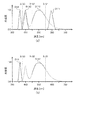
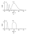
- 3A and 3B show the spectral intensity distribution of the irradiation light L emitted from the electronic scope 100 in each observation mode.
- 3A shows the spectral intensity distribution of the irradiation light L (normal light) in the normal observation mode
- FIG. 3B shows the spectral intensity distribution of the irradiation light L (special light) in the special observation mode.
- the horizontal axis of the spectral intensity distribution shown in FIG. 3 indicates the wavelength (nm), and the vertical axis indicates the intensity of the irradiation light L. Note that the vertical axis is standardized so that the maximum intensity value is 1.
- FIG. 3A shows intensity distributions D111 to D113 and D18 of light emitted from the first to third light source units 111 to 113 and the LED 18.
- the cutoff wavelengths ⁇ 131 to ⁇ 133 of the dichroic mirrors 131 to 133 are indicated by dotted lines.
- a region indicated by a solid line is a region that is emitted from the electronic scope 100 and used as the illumination light L.
- a region indicated by a broken line is a region that is not emitted from the light source device 201 and is not used as the illumination light L.
- the spectral intensity distribution D111 of light emitted from the first light source unit 111 has a steep intensity distribution having a peak at a wavelength of about 650 nm.
- the spectral intensity distribution D112 of light emitted from the second light source unit 112 has peaks at a wavelength of about 450 nm and a wavelength of about 550 nm. These two peaks are the peak of the intensity distribution of the light emitted from the blue LED 112 and the peak of the spectral intensity distribution of the fluorescence emitted from the green phosphor.
- the spectral intensity distribution D113 of light emitted from the third light source unit 113 has a steep intensity distribution having a peak at a wavelength of about 450 nm.
- the spectral intensity distribution D18 of the light emitted from the LED 18 has a steep intensity distribution having a peak at a wavelength of about 415 nm.
- the electronic scope 100 emits illumination light L having a wide wavelength band from the ultraviolet region (part of near ultraviolet) to the red region.
- the spectral intensity distribution of the illumination light L is the sum of the areas indicated by the solid lines in the spectral intensity distributions D111 to D113 and D18 shown in FIG.
- the LED 18 may not be driven to emit light. Even when the LED 18 is not driven to emit light, the illumination light L is emitted with a wide wavelength band from blue to red. By photographing the subject using the illumination light L, a normal color photographed image can be obtained.
- the second light source unit 112 and the LED 18 are driven to emit light, and the first, third, and fourth light source units 111, 113, and 114 are not driven to emit light.
- the intensity around the wavelength of 415 nm, which is the absorbance peak of hemoglobin is relatively higher than the intensity of other wavelength bands, and a captured image in which the surface blood vessels are emphasized can be obtained.
- the light emitted from the second light source unit 112 includes light having a wavelength near 550 nm, which is another peak of the absorbance of hemoglobin. Therefore, by driving the second light source unit 112 to emit light together with the LED 18, the brightness of the captured image can be increased while maintaining the state where the surface blood vessels are emphasized.
- the electronic endoscope system 1 includes the plurality of light source units 111 to 114 and the LEDs 18.
- the light sources 111 to 114 and the LED 18 are individually controlled to emit light according to the observation mode. Therefore, by selecting which one of the light source units 111 to 114 and the LED 18 is driven to emit light, and changing the drive current, the spectral intensity characteristic of the irradiation light L can be switched to one corresponding to the observation mode. it can.
- the electronic endoscope system 1 of the present embodiment has a twin mode in which shooting is performed while the normal observation mode and the special observation mode can be alternately switched as the observation mode.
- the twin mode the observation mode is alternately switched between the normal observation mode and the special observation mode for each frame of the captured image. Therefore, the light emission control of the light source units 111 to 114 and the LED 18 is also switched for each frame of the photographing apparatus. Specifically, when the observation mode is the normal observation mode, the first to third light source units 111 to 113 and the LED 18 are driven to emit light, and the fourth light source unit 114 is not driven to emit light. Further, according to one embodiment, the LED 18 is not driven to emit light.
- the second light source unit 112 and the LED 18 are driven to emit light, and the first, third, and fourth light source units 111, 113, and 114 are not driven to emit light.
- the captured image (normally captured image) captured in the normal observation mode and the captured image (special captured image) captured in the special observation mode are combined by the subsequent signal processing circuit 28. Thereby, the normal captured image and the special captured image are displayed side by side on the monitor 300. Therefore, according to one embodiment, the light source driving circuits 17 and 141 to 144 are configured to generate control signals for individually controlling the light emission of the LED 18 and the light source device 201.
- the electronic scope 100 includes a solid-state imaging device 14 configured to capture an image of a subject at a predetermined frame period and generate an image signal.
- the light source driving circuits 17 and 141 to 144 include one frame of the image signal.
- it is preferable that at least a first control signal for driving the light source device 201 to emit light and a second control signal for driving at least the LED 18 to be switched alternately are generated.
- both the light emitted from the LED 18 and the light emitted from the fourth light source unit 114 are light in a purple wavelength band. Therefore, when the subject is illuminated with light in the purple wavelength band, only one of the LED 18 and the fourth light source unit 114 needs to emit light.
- the purple LED light emitted from the fourth light source unit 114 is irradiated to the subject through the LCB 11.
- the LCB 11 has a characteristic of transmitting visible light, but this transmittance varies depending on the wavelength band, and becomes smaller as the wavelength of light becomes shorter, for example.
- the LCB 11 has a long shape of 1 meter or more from the connection portion 102 of the electronic scope 100 to the distal end portion of the insertion tube 101. Therefore, when the light quantity of the purple LED light incident on the LCB 11 is 100%, the light quantity of the purple LED light emitted from the distal end portion of the insertion tube 101 through the LCB 11 is reduced to about 40%, for example. As a result, the amount of purple LED light applied to the subject decreases, and the captured image may become dark. On the other hand, when the LED 18 disposed at the distal end portion of the insertion tube 101 is caused to emit light instead of the fourth light source unit 114, the purple LED light emitted from the LED 18 loses light amount due to transmission through the LCB 11.
- the light source driving devices 17 and 141 to 144 generate control signals for individually controlling the light emission of the LED 18 (light emitting element) and the light source device 201 according to each of a plurality of modes.
- the light source drive circuits 17, 141 to 144 generate a first control signal for driving to emit at least the light source device 201 in the first mode, and a second control signal for driving to emit at least the LED 18 in the second mode.
- LED18 which inject
- the light source units 111 to 113 are arranged in the light source device 201 of the processor 200.
- the LCB 11 has a relatively high transmittance with respect to blue, green, and red light having wavelengths longer than violet among visible light. Therefore, even if the light source units 111 to 113 are arranged in the light source device 201, the light quantity loss of the light emitted from these light source units 111 to 113 hardly occurs in the LCB 11.
- the light source device 201 shown in FIG. 2 has the 4th light source unit 114 which has purple LED
- embodiment of this invention is not limited to this structure.
- the light source device 201 may not include the light source unit 114.
- various types of electronic scopes 100 are detachably connected to the processor 200. Therefore, it is desirable that the light source device 201 of the processor 200 has the fourth light source unit 114 in preparation for the case where the electronic scope 100 that does not have the LED 18 is connected to the processor 200 for use.
- the electronic endoscope system 1 according to the second embodiment is the same as the electronic endoscope system 1 according to the first embodiment except that the configuration of the light source device 201 of the processor 200 is different.
- FIG. 4 is a block diagram of the light source device 201 included in the processor 200 in the electronic endoscope system 1 according to the second embodiment.
- the light source device 201 includes first and second light source units 211 and 212.
- the first and second light source units 211 and 212 are individually controlled to emit light by control signals generated by the first and second light source drive circuits 241 and 242, respectively.
- the first light source unit 211 is a red LED (Light Emitting Diode) that emits light in a red wavelength band (for example, a wavelength of 620 to 680 nm).
- the second light source unit 212 includes a blue LED that emits light in a blue wavelength band (for example, a wavelength of 430 to 470 nm) and a phosphor. The phosphor is excited by blue LED light emitted from the blue LED, and emits fluorescence in a green wavelength band (for example, a wavelength of 460 to 600 nm).
- Collimating lenses 221 and 222 are arranged in front of the light emission directions of the light source units 211 and 212, respectively.
- the red LED light emitted from the first light source unit 211 is converted into parallel light by the collimator lens 221 and is incident on the dichroic mirror 231.
- the light emitted from the second light source unit 212 that is, the blue LED light and the green fluorescence is converted into parallel light by the collimator lens 222 and is incident on the dichroic mirror 231.
- the dichroic mirror 231 combines the optical path of the light emitted from the first light source unit 211 and the optical path of the light emitted from the second light source unit 212.
- the dichroic mirror 231 has a cutoff wavelength in the vicinity of a wavelength of 600 nm, transmits light having a wavelength longer than the cutoff wavelength, and reflects light having a wavelength shorter than the cutoff wavelength. Yes. Therefore, the red LED light emitted from the first light source unit 211 passes through the dichroic mirror 231, and the light emitted from the second light source unit 212 is reflected by the dichroic mirror 231. Thereby, the optical path of red LED light, the optical path of blue LED light, and green fluorescence are combined. The light whose optical path is synthesized by the dichroic mirror 231 is emitted as illumination light L from the light source device 201.
- FIG. 5 shows the spectral intensity distribution of the irradiation light L emitted from the electronic scope 100 in each observation mode.
- 5A shows a spectral intensity distribution of the irradiation light L (normal light) in the normal observation mode
- FIG. 5B shows a spectral intensity distribution of the irradiation light L (special light) in the special observation mode.
- the horizontal axis of the spectral intensity distribution shown in FIG. 5 indicates the wavelength (nm), and the vertical axis indicates the intensity of the irradiation light L. Note that the vertical axis is standardized so that the maximum intensity value is 1.
- FIG. 5A shows spectral intensity distributions D211, D212, and D18 of light emitted from the first and second light source units 211 and 212 and the LED 18.
- the cutoff wavelength ⁇ 231 of the dichroic mirror 231 is indicated by a dotted line.
- a region indicated by a solid line is a region that is emitted from the electronic scope 100 and used as the illumination light L.
- the optical path of the light emitted from the light source units 211 and 212 is synthesized by the dichroic mirror 231, and the LED 18 is driven to emit light, so that the electronic scope 100 starts from the ultraviolet region (part of near ultraviolet) to red.
- Irradiation light L (normal light) having a wide wavelength band over the region is emitted.
- the spectral intensity distribution of the irradiation light L (normal light) is the sum of the areas indicated by the solid lines in the spectral intensity distributions D211, D212, and D18 shown in FIG.
- the second light source unit 212 and the LED 18 are driven to emit light, and the first light source unit 211 is not driven to emit light.
- the driving current of the second light source unit 212 is set smaller than the driving current in the normal observation mode.
- the intensity around the wavelength of 415 nm, which is the absorbance peak of hemoglobin is relatively higher than the intensity in other wavelength bands, and the captured image in which the surface blood vessels are emphasized is obtained.
- the light emitted from the light source unit 212 includes light having a wavelength near 550 nm, which is another peak of the absorbance of hemoglobin. Therefore, by driving the light source unit 212 to emit light together with the light source unit 211, the brightness of the photographed image can be increased while maintaining the state where the surface blood vessels are emphasized.
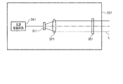
- the electronic endoscope system 1 according to the third embodiment differs from the first and second embodiments in that the light source device 201 includes an optical filter 351 that transmits only light in a specific wavelength band. Is different.
- FIG. 6 is a block diagram of the light source device 201 included in the processor 200 in the electronic endoscope system 1 according to the third embodiment.
- the light source device 201 includes a light source unit 311.
- the light source unit 311 is controlled to emit light by a control signal generated by the light source driving circuit 341.
- the light source unit 311 includes a blue LED that emits light in a blue wavelength band (for example, a wavelength of 430 to 470 nm) and a phosphor.
- the phosphor is excited by blue LED light emitted from the blue LED, and emits fluorescence in a green wavelength band (for example, a wavelength of 460 to 600 nm).
- pseudo white light is emitted from the light source unit 311.
- Light emitted from the light source unit 311 is converted into parallel light by the collimator lens 321.
- the light source device 201 includes an optical filter 351 that can be inserted into and removed from the optical path of light emitted from the light source unit 311.
- the optical filter 351 has a filter characteristic that transmits only light in a wavelength band near a wavelength of 550 nm.
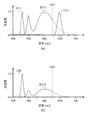
- FIG. 7 shows the spectral intensity distribution of the irradiation light L emitted from the electronic scope 100 in each observation mode.
- FIG. 7A shows the spectral intensity distribution of the irradiation light L (normal light) in the normal observation mode
- FIG. 7B shows the spectral intensity distribution of the irradiation light L (special light) in the special observation mode.
- the horizontal axis of the spectral intensity distribution shown in FIG. 7 indicates the wavelength (nm), and the vertical axis indicates the intensity of the irradiation light L. Note that the vertical axis is standardized so that the maximum intensity value is 1.
- the spectral intensity distribution D311 of light emitted from the light source unit 311 has peaks at wavelengths of about 450 nm and about 550 nm. These two peaks are the peaks of the spectral intensity distribution of blue LED light and green fluorescence, respectively.
- the spectral intensity distribution D18 of light emitted from the LED 18 has a peak at a wavelength of 415 nm.
- the light source unit 311 and the LED 18 are driven to emit light.
- the optical filter 351 is inserted on the optical path. Therefore, the light emitted from the light source unit 311 is limited to light having intensity only in the wavelength band near the wavelength of 550 nm by the optical filter 351.
- the intensities in the vicinity of wavelengths 415 nm and 550 nm, which are the absorption peaks of hemoglobin, are relatively higher than the intensities in other wavelength bands, and the surface blood vessels are emphasized. A photographed image can be obtained.
- the light source device 201 is mounted on the processor 200.
- the light source device 201 is preferably mounted on the electronic scope 100.
- the light source device 201 may be provided in the connection unit 102 or an operation unit that is provided between the connection unit 102 and the distal end portion 101A and operates the electronic scope 100 by the surgeon.
- the light (first light) emitted from the light source device 201 is emitted to the LCB 11 and guided to the tip portion 101A via the LCB 11.
- the light source device 201 is preferably a component device of the electronic endoscope system 1 as a separate device from the processor 200.
- the light source unit 311 is not limited to an LED having a phosphor.
- the light source unit 311 may be a lamp that emits white light, such as a xenon lamp.
- Embodiments of the present invention are not limited to those described above, and various modifications are possible within the scope of the technical idea of the present invention.
- the embodiment of the present invention also includes contents appropriately combined with embodiments or the like clearly shown in the specification or obvious embodiments.
- each light source unit has an LED.
- the present invention is not limited to this, and an LD (Laser ⁇ Diode) can be adopted for each light source unit.
- the LED 18 disposed at the distal end portion of the insertion tube 101 may employ an LD instead of the LED.
- the tip of the insertion tube 101 has one LED 18, but the present invention is not limited to this.
- a plurality of LEDs 18 may be disposed at the distal end portion 101 ⁇ / b> A of the insertion tube 101.
- each light emitted from the LED 18 provided at the tip 101A has a wavelength band in which the light transmittance in the LCB 11 is equal to or lower than that emitted from the light source device 201. It is preferable from the point that the fall of light quantity can be suppressed efficiently.
Landscapes
- Health & Medical Sciences (AREA)
- Life Sciences & Earth Sciences (AREA)
- Physics & Mathematics (AREA)
- Surgery (AREA)
- Optics & Photonics (AREA)
- Engineering & Computer Science (AREA)
- Medical Informatics (AREA)
- General Health & Medical Sciences (AREA)
- Pathology (AREA)
- Nuclear Medicine, Radiotherapy & Molecular Imaging (AREA)
- Biomedical Technology (AREA)
- Heart & Thoracic Surgery (AREA)
- Biophysics (AREA)
- Molecular Biology (AREA)
- Animal Behavior & Ethology (AREA)
- Radiology & Medical Imaging (AREA)
- Public Health (AREA)
- Veterinary Medicine (AREA)
- Astronomy & Astrophysics (AREA)
- General Physics & Mathematics (AREA)
- Microelectronics & Electronic Packaging (AREA)
- Signal Processing (AREA)
- Endoscopes (AREA)
- Instruments For Viewing The Inside Of Hollow Bodies (AREA)
Abstract
L'invention concerne un endoscope électronique capable d'empêcher la réduction de la quantité de lumière dans une bande de longueurs d'ondes souhaitée et qui comporte : un tube d'insertion qui est conçu pour être inséré dans une cavité corporelle, et qui est équipé d'un orifice d'émission de lumière au niveau de son extrémité avant ; un guide de lumière qui est conçu pour guider un premier rayon lumineux jusqu'à l'extrémité avant du tube d'insertion pour une émission à partir de là ; et un élément électroluminescent qui est conçu pour émettre, à partir de l'extrémité avant, un second rayon lumineux d'une bande de longueurs d'ondes présentant une transmittance de la lumière inférieure au niveau du guide de lumière à celle de la bande de longueurs d'ondes du premier rayon lumineux. Le second rayon lumineux allant de l'élément électroluminescent jusqu'au second orifice d'émission de rayons lumineux disposé au niveau de l'extrémité avant présente une longueur de trajet optique plus courte que celle du premier rayon lumineux dans le guide de lumière.
Priority Applications (4)
| Application Number | Priority Date | Filing Date | Title |
|---|---|---|---|
| CN201780038171.5A CN109310285B (zh) | 2016-09-01 | 2017-08-24 | 电子镜及电子内窥镜系统 |
| DE112017004396.4T DE112017004396T5 (de) | 2016-09-01 | 2017-08-24 | Elektronisches endoskop und elektronisches endoskopsystem |
| JP2018537206A JP6732029B2 (ja) | 2016-09-01 | 2017-08-24 | 電子スコープ及び電子内視鏡システム |
| US16/308,455 US20190269309A1 (en) | 2016-09-01 | 2017-08-24 | Electronic scope and electronic endoscope system |
Applications Claiming Priority (2)
| Application Number | Priority Date | Filing Date | Title |
|---|---|---|---|
| JP2016-170601 | 2016-09-01 | ||
| JP2016170601 | 2016-09-01 |
Publications (1)
| Publication Number | Publication Date |
|---|---|
| WO2018043293A1 true WO2018043293A1 (fr) | 2018-03-08 |
Family
ID=61300904
Family Applications (1)
| Application Number | Title | Priority Date | Filing Date |
|---|---|---|---|
| PCT/JP2017/030383 Ceased WO2018043293A1 (fr) | 2016-09-01 | 2017-08-24 | Endoscope électronique et système d'endoscope électronique |
Country Status (5)
| Country | Link |
|---|---|
| US (1) | US20190269309A1 (fr) |
| JP (1) | JP6732029B2 (fr) |
| CN (1) | CN109310285B (fr) |
| DE (1) | DE112017004396T5 (fr) |
| WO (1) | WO2018043293A1 (fr) |
Cited By (1)
| Publication number | Priority date | Publication date | Assignee | Title |
|---|---|---|---|---|
| WO2023276497A1 (fr) * | 2021-06-30 | 2023-01-05 | Hoya株式会社 | Processeur pour endoscope et système endoscopique |
Families Citing this family (3)
| Publication number | Priority date | Publication date | Assignee | Title |
|---|---|---|---|---|
| JP7000933B2 (ja) * | 2017-12-27 | 2022-01-19 | カシオ計算機株式会社 | 撮像装置及び撮像方法 |
| WO2019131586A1 (fr) | 2017-12-27 | 2019-07-04 | カシオ計算機株式会社 | Dispositif de capture d'image et procédé de capture d'image |
| CN115227188A (zh) * | 2022-08-17 | 2022-10-25 | 常州联影智融医疗科技有限公司 | 光源装置及内窥镜系统 |
Citations (5)
| Publication number | Priority date | Publication date | Assignee | Title |
|---|---|---|---|---|
| JP2010063590A (ja) * | 2008-09-10 | 2010-03-25 | Fujifilm Corp | 内視鏡システム、およびその駆動制御方法 |
| JP2011194082A (ja) * | 2010-03-19 | 2011-10-06 | Fujifilm Corp | 内視鏡画像補正装置および内視鏡装置 |
| WO2012056860A1 (fr) * | 2010-10-26 | 2012-05-03 | オリンパスメディカルシステムズ株式会社 | Endoscope |
| WO2012161028A1 (fr) * | 2011-05-26 | 2012-11-29 | オリンパスメディカルシステムズ株式会社 | Dispositif de source de lumière |
| WO2015077684A1 (fr) * | 2013-11-22 | 2015-05-28 | Duke University | Colposcope comportant des émetteurs de lumière et des dispositifs de capture d'image, et procédés associés |
Family Cites Families (24)
| Publication number | Priority date | Publication date | Assignee | Title |
|---|---|---|---|---|
| JP2010099172A (ja) * | 2008-10-22 | 2010-05-06 | Fujifilm Corp | 内視鏡システム |
| WO2010116902A1 (fr) * | 2009-04-09 | 2010-10-14 | オリンパスメディカルシステムズ株式会社 | Dispositif endoscopique |
| JP5606120B2 (ja) * | 2010-03-29 | 2014-10-15 | 富士フイルム株式会社 | 内視鏡装置 |
| JP5467970B2 (ja) * | 2010-08-30 | 2014-04-09 | 富士フイルム株式会社 | 電子内視鏡システム |
| JP5587120B2 (ja) * | 2010-09-30 | 2014-09-10 | 富士フイルム株式会社 | 内視鏡用光源装置 |
| JP5431294B2 (ja) * | 2010-11-16 | 2014-03-05 | 富士フイルム株式会社 | 内視鏡装置 |
| JP5271364B2 (ja) * | 2011-01-07 | 2013-08-21 | 富士フイルム株式会社 | 内視鏡システム |
| JP5550574B2 (ja) * | 2011-01-27 | 2014-07-16 | 富士フイルム株式会社 | 電子内視鏡システム |
| JP5198694B2 (ja) | 2011-02-09 | 2013-05-15 | オリンパスメディカルシステムズ株式会社 | 光源装置 |
| EP2581030B1 (fr) * | 2011-04-11 | 2015-04-29 | Olympus Medical Systems Corp. | Appareil d'endoscope |
| JP2013048792A (ja) * | 2011-08-31 | 2013-03-14 | Fujifilm Corp | 内視鏡装置 |
| JP5872916B2 (ja) * | 2012-01-25 | 2016-03-01 | 富士フイルム株式会社 | 内視鏡システム、内視鏡システムのプロセッサ装置、及び内視鏡システムの作動方法 |
| JP2014036759A (ja) * | 2012-08-17 | 2014-02-27 | Hoya Corp | 電子内視鏡システムおよび内視鏡用光源装置 |
| JP2014121363A (ja) * | 2012-12-20 | 2014-07-03 | Fujifilm Corp | 光源装置、およびこれを用いた内視鏡システム |
| JP6157135B2 (ja) * | 2013-02-07 | 2017-07-05 | オリンパス株式会社 | 光源撮像装置 |
| JP2014171511A (ja) * | 2013-03-06 | 2014-09-22 | Olympus Corp | 被検体観察システム及びその方法 |
| WO2014156253A1 (fr) * | 2013-03-25 | 2014-10-02 | オリンパスメディカルシステムズ株式会社 | Dispositif endoscopique |
| CN104619236B (zh) * | 2013-08-01 | 2016-11-23 | 奥林巴斯株式会社 | 摄像装置 |
| JP6086602B2 (ja) * | 2013-09-27 | 2017-03-01 | 富士フイルム株式会社 | 内視鏡装置 |
| JP5997676B2 (ja) * | 2013-10-03 | 2016-09-28 | 富士フイルム株式会社 | 内視鏡用光源装置、およびこれを用いた内視鏡システム |
| JP6498126B2 (ja) * | 2013-11-28 | 2019-04-10 | オリンパス株式会社 | 蛍光観察装置 |
| JP6085648B2 (ja) * | 2014-08-29 | 2017-02-22 | 富士フイルム株式会社 | 内視鏡用光源装置及び内視鏡システム |
| JP2016049370A (ja) * | 2014-09-02 | 2016-04-11 | Hoya株式会社 | 電子内視鏡システム |
| JP2016152874A (ja) * | 2015-02-20 | 2016-08-25 | Hoya株式会社 | 光源装置 |
-
2017
- 2017-08-24 WO PCT/JP2017/030383 patent/WO2018043293A1/fr not_active Ceased
- 2017-08-24 DE DE112017004396.4T patent/DE112017004396T5/de active Pending
- 2017-08-24 CN CN201780038171.5A patent/CN109310285B/zh active Active
- 2017-08-24 US US16/308,455 patent/US20190269309A1/en not_active Abandoned
- 2017-08-24 JP JP2018537206A patent/JP6732029B2/ja active Active
Patent Citations (5)
| Publication number | Priority date | Publication date | Assignee | Title |
|---|---|---|---|---|
| JP2010063590A (ja) * | 2008-09-10 | 2010-03-25 | Fujifilm Corp | 内視鏡システム、およびその駆動制御方法 |
| JP2011194082A (ja) * | 2010-03-19 | 2011-10-06 | Fujifilm Corp | 内視鏡画像補正装置および内視鏡装置 |
| WO2012056860A1 (fr) * | 2010-10-26 | 2012-05-03 | オリンパスメディカルシステムズ株式会社 | Endoscope |
| WO2012161028A1 (fr) * | 2011-05-26 | 2012-11-29 | オリンパスメディカルシステムズ株式会社 | Dispositif de source de lumière |
| WO2015077684A1 (fr) * | 2013-11-22 | 2015-05-28 | Duke University | Colposcope comportant des émetteurs de lumière et des dispositifs de capture d'image, et procédés associés |
Cited By (2)
| Publication number | Priority date | Publication date | Assignee | Title |
|---|---|---|---|---|
| WO2023276497A1 (fr) * | 2021-06-30 | 2023-01-05 | Hoya株式会社 | Processeur pour endoscope et système endoscopique |
| JP2023006137A (ja) * | 2021-06-30 | 2023-01-18 | Hoya株式会社 | 内視鏡用プロセッサ、内視鏡システム |
Also Published As
| Publication number | Publication date |
|---|---|
| CN109310285A (zh) | 2019-02-05 |
| JP6732029B2 (ja) | 2020-07-29 |
| CN109310285B (zh) | 2021-05-28 |
| JPWO2018043293A1 (ja) | 2019-02-14 |
| DE112017004396T5 (de) | 2019-05-23 |
| US20190269309A1 (en) | 2019-09-05 |
Similar Documents
| Publication | Publication Date | Title |
|---|---|---|
| US9456738B2 (en) | Endoscopic diagnosis system | |
| US9918613B2 (en) | Endoscope system and operating method thereof | |
| JP6878647B2 (ja) | 内視鏡用光源装置及び内視鏡システム | |
| CN106535739A (zh) | 内窥镜系统以及内窥镜用光源装置 | |
| JP2017209530A (ja) | 内視鏡用光源装置及び内視鏡システム | |
| WO2019044802A1 (fr) | Dispositif de source de lumière pour endoscope et système d'endoscope | |
| CN107072508A (zh) | 观察系统 | |
| JP6438062B2 (ja) | 内視鏡システム | |
| JP2016049370A (ja) | 電子内視鏡システム | |
| JP6732029B2 (ja) | 電子スコープ及び電子内視鏡システム | |
| WO2018216276A1 (fr) | Système d'observation et appareil de commande de sources de lumière | |
| JP6203127B2 (ja) | 内視鏡用光源装置及び内視鏡システム | |
| WO2017141415A1 (fr) | Dispositif de source de lumière destiné à un endoscope | |
| JP6138386B1 (ja) | 内視鏡装置及び内視鏡システム | |
| CN111818837A (zh) | 内窥镜系统 | |
| JP6277068B2 (ja) | 内視鏡用光源装置及び内視鏡システム | |
| WO2017141416A1 (fr) | Dispositif de source de lumière destiné à un endoscope | |
| JP2017099455A (ja) | 内視鏡システム及びその制御方法 | |
| JP7338845B2 (ja) | 内視鏡システムおよび内視鏡システムの作動方法 | |
| JP7211971B2 (ja) | 電子内視鏡システム | |
| JP6572065B2 (ja) | 内視鏡用光源装置 | |
| WO2016203983A1 (fr) | Dispositif endoscopique | |
| JP2019000148A (ja) | 内視鏡システム |
Legal Events
| Date | Code | Title | Description |
|---|---|---|---|
| WWE | Wipo information: entry into national phase |
Ref document number: 2018537206 Country of ref document: JP |
|
| 121 | Ep: the epo has been informed by wipo that ep was designated in this application |
Ref document number: 17846298 Country of ref document: EP Kind code of ref document: A1 |
|
| 122 | Ep: pct application non-entry in european phase |
Ref document number: 17846298 Country of ref document: EP Kind code of ref document: A1 |