WO2018043294A1 - Appareil de production de support d'enregistrement et procédé de production de support d'enregistrement - Google Patents
Appareil de production de support d'enregistrement et procédé de production de support d'enregistrement Download PDFInfo
- Publication number
- WO2018043294A1 WO2018043294A1 PCT/JP2017/030387 JP2017030387W WO2018043294A1 WO 2018043294 A1 WO2018043294 A1 WO 2018043294A1 JP 2017030387 W JP2017030387 W JP 2017030387W WO 2018043294 A1 WO2018043294 A1 WO 2018043294A1
- Authority
- WO
- WIPO (PCT)
- Prior art keywords
- recording medium
- fiber
- containing material
- ink receiving
- receiving layer
- Prior art date
- Legal status (The legal status is an assumption and is not a legal conclusion. Google has not performed a legal analysis and makes no representation as to the accuracy of the status listed.)
- Ceased
Links
Images










Classifications
-
- B—PERFORMING OPERATIONS; TRANSPORTING
- B32—LAYERED PRODUCTS
- B32B—LAYERED PRODUCTS, i.e. PRODUCTS BUILT-UP OF STRATA OF FLAT OR NON-FLAT, e.g. CELLULAR OR HONEYCOMB, FORM
- B32B23/00—Layered products comprising a layer of cellulosic plastic substances, i.e. substances obtained by chemical modification of cellulose, e.g. cellulose ethers, cellulose esters, viscose
- B32B23/02—Layered products comprising a layer of cellulosic plastic substances, i.e. substances obtained by chemical modification of cellulose, e.g. cellulose ethers, cellulose esters, viscose in the form of fibres or filaments
-
- B—PERFORMING OPERATIONS; TRANSPORTING
- B41—PRINTING; LINING MACHINES; TYPEWRITERS; STAMPS
- B41J—TYPEWRITERS; SELECTIVE PRINTING MECHANISMS, i.e. MECHANISMS PRINTING OTHERWISE THAN FROM A FORME; CORRECTION OF TYPOGRAPHICAL ERRORS
- B41J2/00—Typewriters or selective printing mechanisms characterised by the printing or marking process for which they are designed
- B41J2/005—Typewriters or selective printing mechanisms characterised by the printing or marking process for which they are designed characterised by bringing liquid or particles selectively into contact with a printing material
- B41J2/01—Ink jet
-
- B—PERFORMING OPERATIONS; TRANSPORTING
- B41—PRINTING; LINING MACHINES; TYPEWRITERS; STAMPS
- B41M—PRINTING, DUPLICATING, MARKING, OR COPYING PROCESSES; COLOUR PRINTING
- B41M5/00—Duplicating or marking methods; Sheet materials for use therein
- B41M5/50—Recording sheets characterised by the coating used to improve ink, dye or pigment receptivity, e.g. for ink-jet or thermal dye transfer recording
- B41M5/52—Macromolecular coatings
-
- D—TEXTILES; PAPER
- D21—PAPER-MAKING; PRODUCTION OF CELLULOSE
- D21H—PULP COMPOSITIONS; PREPARATION THEREOF NOT COVERED BY SUBCLASSES D21C OR D21D; IMPREGNATING OR COATING OF PAPER; TREATMENT OF FINISHED PAPER NOT COVERED BY CLASS B31 OR SUBCLASS D21G; PAPER NOT OTHERWISE PROVIDED FOR
- D21H25/00—After-treatment of paper not provided for in groups D21H17/00 - D21H23/00
- D21H25/18—After-treatment of paper not provided for in groups D21H17/00 - D21H23/00 of old paper as in books, documents, e.g. restoring
Definitions
- the present invention relates to a recording medium manufacturing apparatus and a recording medium manufacturing method.
- Patent Document 1 discloses that paper is regenerated by polishing the image-formed surface of paper and applying a mixture of paper dust and glue generated by the polishing to the surface on which the image has been polished. A paper recycling method is described.
- Patent Document 1 when a mixture of paper powder and glue is applied to the surface on which the image is polished, a spray is used.
- the mixture can be formed on the surface by a single application. Even if it is desired to form a layer as thick as possible (for example, 10 ⁇ m or more), the layer thickness is considered to be only a few ⁇ m at most.
- One of the objects according to some embodiments of the present invention is to provide a recording medium manufacturing apparatus and a recording medium manufacturing method capable of forming a recording layer with a uniform thickness as much as possible with a simple configuration. .
- one of the objects according to some aspects of the present invention is to provide a recording medium manufacturing apparatus and a recording medium manufacturing method capable of forming a recording layer as thick as possible (for example, 10 ⁇ m or more) with a simple configuration. There is.
- one of the objects according to some aspects of the present invention is to provide a recording medium reproducing method capable of repeatedly reproducing the recording medium.
- Another object of some aspects of the present invention is to provide a recording medium reproducing apparatus capable of repeatedly reproducing a recording medium.
- one of the objects according to some aspects of the present invention is to provide a method for manufacturing a recording medium that can be printed favorably, for example, by an ink jet method and can be reproduced thereafter.
- Another object of some aspects of the present invention is to provide a recording medium manufacturing apparatus which can be printed favorably by, for example, an inkjet method and can be reproduced thereafter.
- the present invention has been made to solve at least a part of the problems described above, and can be realized as the following modes or application examples.
- a recording medium manufacturing apparatus includes a carrier that conveys a fiber-containing material containing cellulose fibers and a hydrophobic material, a conveyance unit that conveys a substrate, and the fiber-containing material.
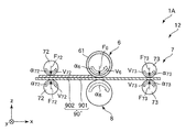
- a transfer portion that transfers the carrier-containing material to the base material, and in the transfer portion, the transport direction of the fiber-containing material by the support body is parallel to the transport direction of the base material by the transport portion ( (Same direction).
- the ink receiving layer composed of the fiber-containing material with a uniform thickness.
- the recording medium manufacturing apparatus carries a fiber-containing material containing cellulose fibers and a hydrophobic material, and conveys a carrier at a first speed V1 and a substrate at a second speed V2. And a transfer unit that transfers the fiber-containing material from the carrier to the substrate.
- the transfer direction of the fiber-containing material by the carrier, and the transfer unit The transport direction of the base material is parallel (same) and satisfies the relationship of V1> V2.
- the ink receiving layer composed of the fiber-containing material can be formed as thick as possible (for example, 10 ⁇ m or more).
- a recording medium manufacturing apparatus includes a carrier that conveys a fiber-containing material including cellulose fibers and a hydrophobic material, a carrier that conveys a base material, and the fiber-containing material.
- a transfer portion that transfers the carrier-containing material to the base material, wherein the transfer portion transports the fiber-containing material in a direction opposite to the transport direction of the base material by the transport portion. It is characterized by being.
- the ink receiving layer composed of the fiber-containing material can be formed as thick as possible (for example, 10 ⁇ m or more).
- a recording medium manufacturing apparatus includes a carrier that conveys a fiber-containing material containing cellulose fibers and a hydrophobic material, a conveyance unit that conveys a substrate, and the fiber-containing material.
- W2 weight of the fiber-containing material carried on the carrier
- the ink receiving layer composed of the fiber-containing material can be formed as thick as possible (for example, 10 ⁇ m or more).
- the carrier is a rotating body. Thereby, the carrier can stably transfer the fiber-containing material to the substrate together with the transfer portion while rotating.
- the rotating body has a dielectric layer on an outer peripheral portion.
- the apparatus structure which transfers a fiber containing material can be simplified.
- the transfer unit transfers the fiber-containing material by electrostatic force.
- the fiber-containing material can be easily attached to the base material by a simple method of using electrostatic force.
- the transfer unit transfers the fiber-containing material while sandwiching the base material with the carrier.
- the transfer unit separates the carrier on the base material to be larger than the thickness of the fiber-containing material layer transferred to the base material. It is preferable to transfer the fiber-containing material.
- non-contact transfer can be performed, and for example, noise during transfer can be suppressed.
- the fiber-containing material can be uniformly applied by, for example, electrostatic application.
- the average length of the cellulose fibers is 1 ⁇ m or more and 100 ⁇ m or less.
- the fiber-containing material can be uniformly applied by, for example, electrostatic application.
- a recording medium manufacturing method conveys a fiber-containing material containing cellulose fibers and a hydrophobic material at a first speed V1, and conveys a substrate at a second speed V2.
- the recording layer composed of the fiber-containing material can be formed as thick as possible (for example, 10 ⁇ m or more).
- a recording medium manufacturing method includes supporting a fiber-containing material including cellulose fibers and a hydrophobic material on a carrier, and transferring the fiber-containing material from the carrier to a substrate.
- a transfer step wherein the weight per unit area of the fiber-containing material supported on the carrier is W1, and the weight per unit area of the fiber-containing material transferred to the substrate is W2. It satisfies the relationship of W2 / W1> 1.0.
- the recording layer composed of the fiber-containing material can be formed as thick as possible (for example, 10 ⁇ m or more).
- a recording medium reproduction method is a method of newly reproducing a recording medium from a recording medium having a recording surface on which information is recorded.
- a first step of removing the information recording material provided for recording from the recording surface, and at least a part of the recording surface from which the information recording material has been removed include a fiber containing fiber-containing material including cellulose fibers.
- a second step of forming a layer is a method of newly reproducing a recording medium from a recording medium having a recording surface on which information is recorded.
- the recording medium in which information is recorded and is no longer needed is reproduced as a recording medium in which the information is deleted and information can be recorded again.
- this regeneration can be performed repeatedly, so that it is economical and environmentally friendly.
- Application Example 19 In the recording medium reproducing method described in Application Example 18, in the first step, it is preferable that the information recording material is removed by at least one of cutting, scraping, grinding, and polishing. .
- the information recording material can be removed by appropriately selecting from at least one of cutting, scraping, grinding and polishing, and therefore the information recording material can be easily and quickly removed.
- Application Example 20 In the recording medium reproducing method according to Application Example 19, in the first step, at least one of a bite, a scraper, a flap brush, and an elastic grinder is used as a removing member for removing the information recording material. It is preferable to use one.
- the removal of the information recording material can be performed by appropriately selecting from at least one machining among cutting, scraping, grinding and polishing, and a tool suitable for the selected machining can be used. it can.
- Application Example 21 In the recording medium reproducing method according to any one of Application Examples 18 to 20, it is preferable that in the first step, the information recording material is removed while heating the information recording material. .
- the information recording material is softened, so that the information recording material can be easily removed.
- the fiber-containing layer is formed by electrostatic coating.
- the fiber-containing material can be easily attached to the recording surface on demand by a relatively simple method of electrostatic coating.
- the recording medium reproducing method according to Application Example 22 preferably includes a step of forming a symbol including information on the fiber-containing layer. Thereby, the information regarding a fiber content layer can be checked (acquired) as needed.
- the average aspect ratio of the cellulose fibers is preferably less than 3.
- the fiber-containing material includes a hydrophobic material that covers at least a part of the cellulose fiber, and the hydrophobic material
- the conductive material preferably contains a thermoplastic resin.
- the fiber-containing layer has more stable charging characteristics (particularly negative chargeability). Moreover, it becomes possible to bind cellulose fibers by heat processing by including a thermoplastic resin.
- content Wa when the content Wa is equal to or higher than the lower limit value, it is possible to secure the binding force of the cellulose fibers and to prevent the cellulose fibers from falling off the fiber-containing layer. If content Wa is less than the said upper limit, it can suppress that the hydrophobicity of a fiber content layer becomes high too much, for example, flips ink, and can improve printing quality.
- the glass transition temperature of the thermoplastic resin is preferably 50 ° C. or more and 200 ° C. or less.
- the glass transition temperature of a thermoplastic resin is more than the said lower limit, it can suppress that a fiber content layer peels off by heating of a friction grade, and can suppress that the intensity of a fiber content layer falls. Can do. If the glass transition temperature of the thermoplastic resin is equal to or lower than the upper limit value, for example, when the fiber-containing material to be the fiber-containing layer is fixed by heating and pressurizing, it is necessary to heat the recording medium to a temperature higher than the upper limit value. In addition, the cellulose fibers can be prevented from being damaged by heat.
- the hydrophobic material preferably contains a charge control agent.
- the fiber-containing material that becomes the fiber-containing layer can have stable chargeability and greater chargeability.
- the hydrophobic material preferably contains a white pigment. Thereby, the whiteness of a fiber content layer can be adjusted suitably.
- the average length of the cellulose fibers is preferably 1 ⁇ m or more and 100 ⁇ m or less.
- the length of the cellulose fibers can be reduced by a dry method, and the cellulose fibers can be prevented from being entangled with each other.
- the material can be uniformly electrostatically applied.
- the fiber-containing layer is an ink receiving layer that receives ink.
- ink ejected from an ink receiving layer for example, a print head of an ink jet printer, can be easily received and permeated. As a result, the ink receiving layer is printed.
- a recording medium reproducing apparatus is an apparatus that newly reproduces a recording medium from a recording medium having a recording surface on which information is recorded, and is provided on the recording surface to record the information.
- the recording medium in which information is recorded and is no longer needed is reproduced as a recording medium in which the information is deleted and information can be recorded again.
- this regeneration can be performed repeatedly, so that it is economical and environmentally friendly.
- the material removing unit includes a removing member that removes the information recording material by rotating, and applies a tensile force to the recording medium. However, it is preferable to remove the information recording material with the removing member.
- the information recording material of the recording medium can be easily removed.
- the material removing unit rotates the information recording material by rotating with a transport unit that transports the recording medium having the recording surface.
- a pair of first rollers that are disposed on the upstream side in the transport direction of the recording medium with respect to the removal member, and rotate while sandwiching the recording medium;
- a pair of second rollers that are disposed on the downstream side in the transport direction with respect to the removing member and rotate while sandwiching the recording medium, and the speed of the pair of first rollers is Va, and the pair of first rollers
- the clamping force of the roller is Fa
- the speed of the pair of second rollers is Vb
- the clamping force of the pair of second rollers is Fb
- the speed of the removing member is Vc
- the grinding force of the removing member is Fc
- the recording medium when removing the information recording material on the recording surface, the recording medium can be pulled toward the downstream side in the transport direction, and thus the information recording material can be removed by one transport (one pass). It can be performed stably.
- a recording medium manufacturing method includes a layer forming step of forming a recording layer made of a fiber-containing material containing cellulose fibers and a hydrophobic material on a substrate, and a surface of the recording layer. And a solidification step for solidifying the recording layer.
- a recording medium having a recording layer that is favorably printed by the ink jet method it is possible to manufacture a recording medium having a recording layer that is favorably printed by the ink jet method.
- a recording medium on which the recording layer is printed may be unnecessary.
- the recording layer is removed from the printed recording medium, and then a new recording layer can be formed.
- the printed recording medium is reproduced (manufactured) as a recording medium that can be printed again.
- the recording medium manufacturing method according to Application Example 35 preferably includes a step of forming a symbol including information on the recording layer. Thereby, the information regarding a fiber content layer can be checked (acquired) as needed.
- the recording layer is formed by electrostatic coating in the layer forming step.
- the fiber-containing material can be easily attached to the base material by a relatively simple method of electrostatic coating.
- Application Example 38 In the recording medium manufacturing method according to Application Example 36 or 37, it is preferable that the recording layer is neutralized during the processing step or between the processing step and the solidification step. . Accordingly, when static electricity is applied to the recording layer, the static electricity can be discharged.
- the average aspect ratio of the cellulose fibers is preferably less than 3. Thereby, it can suppress that a cellulose fiber entangles, Therefore The fiber containing material used as a recording layer can be electrostatically apply
- the treatment preferably includes a flattening treatment for flattening a surface of the recording layer.
- the surface of the recording layer can be made smooth, that is, the surface of the recording layer is flattened.
- the treatment includes a semi-solidification process for semi-solidifying the surface of the recording layer.
- the process includes a pressurizing process for pressurizing the recording layer.
- the treatment includes a flattening treatment for flattening a surface of the recording layer and a semi-solidification of the surface of the recording layer.
- the processing step it is preferable to perform the processing in the order of the flattening processing and the semi-solidifying processing.
- the treatment includes a flattening treatment for flattening a surface of the recording layer, a pressurizing treatment for pressurizing the recording layer, and the recording layer.
- the flattening process, the pressurizing process, and the semisolidifying process are preferably performed in this order.
- Application Example 45 In the method for manufacturing a recording medium according to any one of Application Examples 35 to 44, it is preferable that the solidification step is performed by heating and pressurizing the recording layer. Thereby, the recording layer can be fixed to the substrate.
- a recording medium manufacturing apparatus includes a recording layer forming unit that forms a recording layer made of a fiber-containing material including cellulose fibers and a hydrophobic material on a base material, and a surface of the recording layer. It is characterized by comprising a processing section for performing processing for adjusting properties and a solidifying section for solidifying the recording layer.
- a recording medium having a recording layer that is favorably printed by the ink jet method it is possible to manufacture a recording medium having a recording layer that is favorably printed by the ink jet method.
- a recording medium on which the recording layer is printed may be unnecessary.
- the recording layer is removed from the printed recording medium, and then a new recording layer can be formed.
- the printed recording medium is reproduced (manufactured) as a recording medium that can be printed again.
- a recording medium reproduction method includes a removal step of removing the information recording material used for recording information from the base material, and a fiber-containing material including cellulose fibers and a hydrophobic material.
- a layer forming step for forming the recording layer on the substrate includes a processing step for performing a process for adjusting the surface properties of the recording layer, and a solidifying step for solidifying the recording layer.
- a recording medium having a recording layer that is favorably printed by the ink jet method it is possible to manufacture a recording medium having a recording layer that is favorably printed by the ink jet method.
- a recording medium on which the recording layer is printed may be unnecessary.
- the recording layer is removed from the printed recording medium, and then a new recording layer can be formed.
- the printed recording medium is reproduced (manufactured) as a recording medium that can be printed again.
- a recording medium reproducing apparatus includes a material removing unit that removes an information recording material used for recording information from a base material, and a fiber-containing material including cellulose fibers and a hydrophobic material.
- a recording layer forming section for forming the recording layer on the substrate, a processing section for performing a process for adjusting the surface properties of the recording layer, and a solidifying section for solidifying the recording layer.
- a recording medium having a recording layer that is favorably printed by the ink jet method it is possible to manufacture a recording medium having a recording layer that is favorably printed by the ink jet method.
- a recording medium on which the recording layer is printed may be unnecessary.
- the recording layer is removed from the printed recording medium, and then a new recording layer can be formed.
- the printed recording medium is reproduced (manufactured) as a recording medium that can be printed again.
- FIG. 1 is a block diagram showing the main part of the recording medium playback system of the first embodiment.
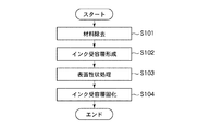
- FIG. 2 is a diagram (flowchart) sequentially illustrating each step performed in the recording medium playback system shown in FIG.
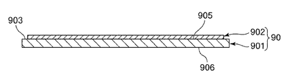
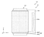
- FIG. 3 is a plan view showing an example of a recording medium manufactured by the recording medium reproducing system shown in FIG. 4 is a cross-sectional view taken along line AA in FIG.
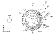
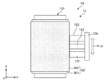
- FIG. 5 is a vertical cross-sectional view showing the material removing unit of the recording medium reproducing apparatus provided in the recording medium reproducing system shown in FIG. 6 is a view as seen from the direction of arrow B in FIG.
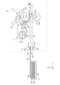
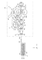
- FIG. 7 is a vertical sectional side view showing the upstream side of the recording medium manufacturing apparatus provided in the recording medium reproducing system shown in FIG.
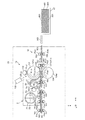
- FIG. 8 is a vertical sectional side view showing the downstream side of the recording medium manufacturing apparatus provided in the recording medium reproducing system shown in FIG.
- FIG. 9 is an enlarged view of a region [C] surrounded by a two-dot chain line in FIG.
- FIG. 10 is a vertical cross-sectional view showing a material removing unit of a recording medium reproducing apparatus provided in the recording medium reproducing system of the second embodiment.
- FIG. 11 is a plan view showing a material removing unit of a recording medium reproducing apparatus provided in the recording medium reproducing system of the third embodiment.
- FIG. 12 is a vertical cross-sectional view sequentially illustrating the operating state of the material removing unit of the recording medium reproducing apparatus provided in the recording medium reproducing system of the fourth embodiment.
- FIG. 13 is a vertical cross-sectional view sequentially illustrating the operating state of the material removing unit of the recording medium reproducing apparatus provided in the recording medium reproducing system of the fourth embodiment.
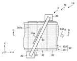
- FIG. 14 is a plan view showing the surface texture processing unit of the recording medium manufacturing apparatus provided in the recording medium reproducing system of the fifth embodiment.
- FIG. 15 is a sectional view taken along the line DD in FIG.
- FIG. 16 is a plan view showing the surface texture processing unit of the recording medium manufacturing apparatus provided in the recording medium reproducing system of the sixth embodiment.
- FIG. 17 is a vertical cross-sectional view showing the surface texture processing unit of the recording medium manufacturing apparatus provided in the recording medium playback system of the seventh embodiment.
- FIG. 18 is a vertical sectional view showing an ink receiving layer forming part of a recording medium manufacturing apparatus provided in the recording medium reproducing system of the eighth embodiment.
- FIG. 19 is a vertical sectional view showing an ink receiving layer forming part of a recording medium manufacturing apparatus provided in the recording medium reproducing system of the ninth embodiment.
- FIG. 20 is a vertical sectional side view showing the upstream side of the recording medium manufacturing apparatus provided in the recording medium reproducing system of the tenth embodiment.
- FIG. 21 is a vertical sectional side view showing the downstream side of the recording medium manufacturing apparatus provided in the recording medium reproducing system of the tenth embodiment.
- FIG. 22 is a vertical sectional side view showing the upstream side of the recording medium manufacturing apparatus provided in the recording medium playback system of the eleventh embodiment.
- FIG. 23 is a vertical sectional side view showing the downstream side of the recording medium manufacturing apparatus provided in the recording medium reproducing system of the eleventh embodiment.
- FIG. 24 is a vertical sectional side view showing the upstream side of the recording medium manufacturing apparatus provided in the recording medium reproducing system of the twelfth embodiment.
- FIG. 1 is a block diagram showing the main part of the recording medium playback system of the first embodiment.
- FIG. 2 is a diagram (flowchart) sequentially illustrating each step performed in the recording medium playback system shown in FIG.
- FIG. 3 is a plan view showing an example of a recording medium manufactured by the recording medium reproducing system shown in FIG. 4 is a cross-sectional view taken along line AA in FIG.
- FIG. 5 is a vertical cross-sectional view showing the material removing unit of the recording medium reproducing apparatus provided in the recording medium reproducing system shown in FIG. 6 is a view as seen from the direction of arrow B in FIG. FIG.
- FIG. 7 is a vertical sectional side view showing the upstream side of the recording medium manufacturing apparatus provided in the recording medium reproducing system shown in FIG. 8 is a vertical sectional side view showing the downstream side of the recording medium manufacturing apparatus provided in the recording medium reproducing system shown in FIG.
- FIG. 9 is an enlarged view of a region [C] surrounded by a two-dot chain line in FIG.
- the xy plane including the x axis and the y axis is the horizontal direction
- the z axis is the vertical direction.
- a direction parallel to the x-axis is also referred to as “x-axis direction (first direction)”, a direction parallel to the y-axis is also referred to as “y-axis direction (second direction)”, and a direction parallel to the z-axis. Is also referred to as “z-axis direction (third direction)”.
- the direction in which the arrow in each direction is directed is called “positive”, and the opposite direction is called “negative”.
- the upper side may be referred to as “upper” or “upper”
- the lower side may be referred to as “lower” or “lower”.
- the left side may be referred to as “upstream side” and the right side may be referred to as “downstream side”.
- the recording medium reproduction method is a method of newly reproducing the recording medium 90 from the recording medium 90 having the first surface 905 (recording surface) on which information is recorded, and is given to the first surface 905 (recording surface).
- the first step of removing the information recording material used for recording information from the first surface 905 (recording surface), and at least a part of the first surface 905 (recording surface) from which the information recording material has been removed include cellulose.
- the recording medium reproducing apparatus 1A is an apparatus for newly reproducing the recording medium 90 from the recording medium 90 having the first surface 905 (recording surface) on which information is recorded, and the first surface 905 (recording surface).
- the material removing unit 12 that removes the information recording material that is provided and used for recording information from the first surface 905 (recording surface), and at least a part of the recording surface from which the information recording material is removed include cellulose fibers.
- This recording medium playback apparatus 1A is an apparatus that can execute a recording medium playback method.
- the recording medium 90 'that has been recorded and no longer needed is reproduced as a recording medium 90 on which the information is erased and information can be recorded again. Further, this reproduction can be repeated.
- a recording medium manufacturing method includes a layer forming step of forming an ink receiving layer 902 (recording layer) made of a fiber-containing material including cellulose fibers and a hydrophobic material on a substrate 901, and an ink receiving layer 902 (recording layer). ) And a solidifying step for solidifying the ink receiving layer 902 (recording layer).
- the recording medium manufacturing apparatus 1B includes an ink receiving layer forming unit 13 (recording layer forming) that forms an ink receiving layer 902 (recording layer) made of a fiber-containing material including cellulose fibers and a hydrophobic material on a substrate 901. Part), a surface property processing unit 14 (processing unit) that performs a process for adjusting the surface property of the ink receiving layer 902 (recording layer), and an ink receiving layer solidifying unit 15 (solidifying) that solidifies the ink receiving layer 902 (recording layer). Part).
- This recording medium manufacturing apparatus 1B is an apparatus capable of executing a recording medium manufacturing method.
- the recording medium reproduction method includes a removal step of removing an information recording material provided for information recording from a base material, and an ink receiving layer 902 composed of a fiber-containing material including cellulose fibers and a hydrophobic material ( A recording layer) on the substrate 901, a processing step for adjusting the surface properties of the ink receiving layer 902 (recording layer), a solidifying step for solidifying the ink receiving layer 902 (recording layer), Have.
- the recording medium reproducing apparatus 1A includes an ink receiving layer that includes a material removing unit 12 that removes an information recording material used for recording information from a base material, and a fiber-containing material including cellulose fibers and a hydrophobic material.
- An ink receiving layer forming portion 13 (recording layer forming portion) for forming 902 (recording layer) on the substrate 901, and a surface property processing portion 14 (processing portion) for performing processing for adjusting the surface properties of the ink receiving layer 902 (recording layer).
- an ink receiving layer solidifying unit 15 solidifying unit that solidifies the ink receiving layer 902 processed by the surface texture processing unit 14 (processing unit).
- a recording medium 90 as described later can be manufactured.
- the ink receiving layer 902 is favorably printed by, for example, an ink jet method.
- the recording medium 90 on which the ink receiving layer 902 is printed may be unnecessary.
- the ink receiving layer 902 is removed from the printed recording medium 90 ', and then a new ink receiving layer 902 is formed.
- the printed recording medium 90 ′ is reproduced (manufactured) as a recording medium 90 that can be printed again.
- the recording medium 90 shown in FIG. 3 can be manufactured.
- the recording medium 90 includes a sheet-like base material 901 and an ink receiving layer 902 formed on the base material 901.
- the ink receiving layer 902 of the unused recording medium 90 can be printed and used.
- various information is recorded in the ink receiving layer 902.
- the various information includes, for example, characters, symbols, figures, patterns, colors, or combinations thereof.
- a marking part (symbol) 904 described later can be recorded.
- recording medium 90 ′ when the recording medium 90 that has been printed and used (hereinafter, this recording medium 90 is referred to as “recording medium 90 ′”) becomes unnecessary, the recording medium 90 ′ is re-used as waste paper. Used.
- the recording medium reproduction system 100 can also be used for this reuse. In this case, the ink receiving layer 902 is removed from the recording medium 90 ′ to obtain a base material 901. Then, by forming the ink receiving layer 902 on the substrate 901 again, the used recording medium 90 is reproduced.
- the recording medium 90 ′ is the recording medium 90 that has been used in the present embodiment, but is not limited to this.
- the recording medium 90 ′ is printed directly on commercially available PPC (Plain Paper Copier) paper. It may have been used after being applied.
- PPC paper can be obtained as the base material 901 by removing at least the printed portion from the PPC paper by the recording medium reproduction system 100. It should be noted that printing on the PPC paper may be performed in any manner such as ink or toner.
- the used recording medium 90 (recording medium 90 ′) is referred to as a “primary recording medium”, and an unused recording medium 90 obtained from the primary recording medium is referred to as a “secondary recording medium”. Can be said.
- the recording medium 90 includes a base material 901 and an ink receiving layer 902.
- the base material 901 is, for example, PPC paper.
- the base material 901 may be a recycled paper manufactured by defibrating waste paper, or may be an OHP sheet (trend spareness) used for an OHP (Over Head Projector).
- the base material 901 is flexible as described above, but is not limited thereto, and may be a rigid body.
- the shape of the base material 901 in plan view (the shape seen from the thickness direction of the base material 901) is a rectangle, but is not limited to this.
- the size is not particularly limited, and may be, for example, A size or B size.
- the base material 901 has a blank portion 903 where the ink receiving layer 902 is not provided at least at a part of the edge of the base material 901 in plan view.
- the blank portion 903 is provided in a strip shape over the entire circumference of the edge portion of the base material 901.
- the width of the blank portion 903 is, for example, preferably from 1 mm to 10 mm, and more preferably from 3 mm to 7 mm. If the width of the blank portion 903 is equal to or greater than the lower limit value, the ink receiving layer 902 can be easily removed from the blank portion 903. Further, if the width of the blank portion 903 is equal to or less than the upper limit value, the area of the ink receiving layer 902 on the base material 901 can be sufficiently ensured to be printable.
- the blank part 903 is provided over the perimeter of the edge part of the base material 901, it is not limited to this, You may be provided in a part of edge part of the base material 901.
- An ink receiving layer 902 is provided on the substrate 901.
- the ink receiving layer 902 is provided on one surface of the base material 901 (the upper first surface 905 in FIG. 4). It may also be provided on the side surface (lower second surface 906 in FIG. 4). Further, the shape of the ink receiving layer 902 in plan view is a rectangle, but is not limited thereto.
- the ink receiving layer 902 is a portion that is printed by an inkjet method (for example, by an inkjet printer), and is a composite (fiber-containing material) that includes cellulose fibers and a hydrophobic material that covers at least part of the cellulose fibers. It is the fiber content layer comprised by these. Since such a fiber-containing layer is an ink receiving layer 902 that receives ink, the ink receiving layer 902 can easily receive and infiltrate ink ejected from the print head of the ink jet printer. As a result, the ink receiving layer 902 is printed. As described above, various kinds of information such as characters are recorded on the ink receiving layer 902 by printing.
- the composite that is the constituent material of the ink receiving layer 902 is a material that is used for storing information, and can also be referred to as an “information recording material”.
- the thickness of the ink receiving layer 902 is, for example, preferably 20 ⁇ m to 100 ⁇ m, and more preferably 30 ⁇ m to 70 ⁇ m. If the thickness of the ink receiving layer 902 is equal to or greater than the lower limit, it is possible to suppress the ink ejected by the ink jet printer from penetrating to the base material 901 below the ink receiving layer 902. Further, if the thickness of the ink receiving layer 902 is equal to or less than the upper limit value, the manufacturing cost of the recording medium 90 can be suppressed. For example, when the thickness of the ink receiving layer 902 is greater than 50 ⁇ m, it is possible to obtain a recording medium 90 that is more excellent in ink absorbability and retention in the ink receiving layer 902.
- the ink receiving layer 902 includes (has) a marking portion (symbol) 904.
- the marking unit 904 includes information regarding the ink receiving layer 902 (fiber-containing layer). Further, in the configuration shown in FIG. 3, one marking portion 904 is provided in the vicinity of one corner of the ink receiving layer 902 that is rectangular in plan view, but the arrangement location and the number of arrangement are not limited to this.
- the marking unit 904 may be a barcode (one-dimensional barcode), but is preferably a QR code (registered trademark) (two-dimensional code) (“QR code” is a registered trademark).
- QR code registered trademark
- the marking unit 904 can carry a relatively large amount of information.
- the marking unit 904 may be, for example, a simple figure, symbol, character, or a combination of these in addition to the barcode or QR code.
- the information regarding the ink receiving layer 902 is not particularly limited, and examples thereof include the following information. Position information of the ink receiving layer 902 with respect to the first surface 905. Area information of the ink receiving layer 902 with respect to the first surface 905. Ink receiving layer 902 thickness information. Information on the composition of the composite that forms the ink receiving layer 902 (for example, the ratio of cellulose fiber to resin).
- the ink receiving layer 902 when the ink receiving layer 902 is removed from the substrate 901 as described above, the ink receiving layer 902 thickness information and the margin portion 903 position and width information are acquired from the marking unit 904 to obtain ink.
- the receiving layer 902 can be easily removed.
- the ink receiving layer 902 is printed by an ink jet printer, information on the composition of the composite forming the ink receiving layer 902 is acquired from the marking unit 904, so that the image of the ink receiving layer 902 can be obtained. Is suitable for printing (for example, whether it is suitable for printing a photograph or printing a character).
- the ink receiving layer 902 is composed of a composite (fiber-containing material) including cellulose fibers and a hydrophobic material covering at least a part of the cellulose fibers. As will be described later, the ink receiving layer 902 is formed by adhering the composite to the base material 901 by electrostatic coating (coating using electrostatic force) by a method similar to the electrophotographic method, and pressurizing and heating. Is done.
- Cellulose fibers are fibers composed of cellulose.
- the cellulose fiber may be a natural fiber, a regenerated fiber, or a semi-synthetic fiber.
- the cellulose fiber may be derived from virgin pulp, may be derived from a cellulose product such as paper (including waste paper, recycled paper, etc.), or cellulose as described above.
- Semi-synthetic fibers obtained by subjecting a material containing to chemical treatment may also be used.
- the cellulose fibers may be powder fibers.
- the cellulose fiber is not particularly limited as long as it is mainly composed of cellulose (narrowly defined cellulose) as a compound and has a fibrous form, and includes hemicellulose and lignin in addition to cellulose (narrowly defined cellulose). It may be.
- the size of the cellulose fibers contained in the ink receiving layer 902 is preferably, for example, an average (number average) length (major axis) of 1 ⁇ m to 100 ⁇ m and a width (minor axis) of 1 ⁇ m to 30 ⁇ m. More preferably, the thickness is 5 ⁇ m or more and 30 ⁇ m or less, and the width is 5 ⁇ m or more and 20 ⁇ m or less.
- the length of the cellulose fiber is made smaller than the lower limit value, the production cost of the cellulose fiber becomes high. However, the production cost can be suppressed within the above range. Furthermore, if the magnitude
- the length of a cellulose fiber is below the said upper limit, it can suppress that a cellulose fiber entangles. Thereby, the uniformity of the charge amount distribution of the powder made of the composite forming the ink receiving layer 902 can be improved, and thus the composite can be uniformly electrostatically applied to the substrate 901.
- size (length, width) of a cellulose fiber is measured using the particle
- This apparatus is an apparatus for measuring particle size and particle shape by uniformly dispersing a sample by an automatic dry dispersion unit and analyzing a still image of the sample.
- the fiber-containing material constituting the ink receiving layer 902 includes a hydrophobic material, and the hydrophobic material covers at least a part of the cellulose fiber.
- the average aspect ratio of the cellulose fibers contained in the ink receiving layer 902 is preferably less than 3, and more preferably 2 or less. If the average aspect-ratio of a cellulose fiber is less than 3, it can suppress that a cellulose fiber entangles. Thereby, the uniformity of the charge amount distribution of the powder made of the composite forming the ink receiving layer 902 can be improved, and thus the composite can be uniformly electrostatically applied to the substrate 901.
- the ink receiving layer 902 can be made more suitable for the ink to permeate during printing. In this way, in particular, the ink absorbability of the ink receiving layer 902 can be increased.
- the average aspect ratio of the cellulose fiber is, for example, a value obtained by dividing the average length of the cellulose fiber measured by the particle image analyzer Morphogi G3 by the average width.
- the average length of a cellulose fiber is 1 micrometer or more and 100 micrometers or less.
- the length of a cellulose fiber can be made small by a dry system, and it can suppress that a cellulose fiber entangles.
- the uniformity of the charge amount distribution of the powder made of the composite forming the ink receiving layer 902 can be improved, and thus the composite can be uniformly electrostatically applied to the substrate 901.
- the hydrophobic material is fused to cellulose fibers by heat treatment, for example, to form a composite.
- the hydrophobic material may cover a part of the surface of the cellulose fiber or may cover the entire surface of the cellulose fiber.
- the hydrophobic material should just be a thing with hydrophobicity higher than a cellulose as a whole, for example, may contain the component (hydrophilic component with a low hydrophobicity) rather than a cellulose.
- the hydrophobic material binds cellulose fibers together to form a porous ink receiving layer 902. Also, by having hydrophobicity, the balance between hydrophobicity and hydrophilicity of the ink receiving layer 902 can be adjusted, and excessive wetting and spreading of the ink when ink is applied to the ink receiving layer 902 is suppressed. In addition, the ink absorbability in the ink receiving layer 902 can be made excellent. Furthermore, the hydrophobic material can make the charging property of the composite excellent in stability by coating the cellulose fiber. Thereby, the ink receiving layer 902 can be suitably formed by electrostatic coating.
- cellulose fibers that are not coated with a hydrophobic material have high affinity with ink, and the ink may ooze.
- the chargeability of the cellulose fiber can be stabilized, and ink bleeding can be suppressed.
- the hydrophobic material contains at least a resin.
- the resin binds cellulose fibers together to form a porous ink receiving layer 902.
- the resin may be in powder form.
- the content of the resin in the ink receiving layer 902 is preferably 10% by mass or more and less than 40% by mass, and more preferably 15% by mass or more and 30% by mass or less.
- the hydrophobic material has a function of binding cellulose fibers together, and also has a function of stabilizing the charging characteristics of the composite by covering the cellulose fibers.
- the hydrophobic material is generally composed of a resin as described later. This resin may be positively charged or negatively charged, but is preferably negatively charged. In general, negatively chargeable resins are particularly excellent in stability of charging characteristics. In addition to the positively chargeable resin, there are many types of negatively chargeable resins, and the characteristics of the resin (for example, melting point, glass transition temperature, bonding strength with cellulose fiber, charge amount, degree of hydrophobicity, etc.) ) Can be easily adjusted, and is advantageous from the viewpoint of reducing the manufacturing cost of the recording medium 90.
- the resin constituting the hydrophobic material for example, a thermoplastic resin, a curable resin, or the like can be used, but it is preferable to use a thermoplastic resin.
- a thermoplastic resin generally more stable charging characteristics (particularly negative chargeability) can be obtained.
- the hydrophobic material contains a curable resin, the heat resistance and durability of the recording medium 90 can be made particularly excellent.
- the hydrophobic material may include a thermoplastic resin and a curable resin in addition to the thermoplastic resin alone.
- thermoplastic resin examples include AS resin, ABS resin, polyethylene, polypropylene, polyolefin such as ethylene-vinyl acetate copolymer (EVA), modified polyolefin, acrylic resin such as polymethyl methacrylate, polyvinyl chloride, polystyrene, and polyethylene.
- EVA ethylene-vinyl acetate copolymer
- acrylic resin such as polymethyl methacrylate, polyvinyl chloride, polystyrene, and polyethylene.
- Polyester such as terephthalate, polybutylene terephthalate, nylon 6, nylon 46, nylon 66, nylon 610, nylon 612, nylon 11, nylon 12, nylon 6-12, nylon 6-66, polyamide (nylon), polyphenylene ether, polyacetal , Polyether, polyphenylene oxide, polyether ether ketone, polycarbonate, polyphenylene sulfide, thermoplastic polyimide, polyetherimide, aromatic Liquid crystal polymers such as reesters, various thermoplastic elastomers such as styrene, polyolefin, polyvinyl chloride, polyurethane, polyester, polyamide, polybutadiene, trans polyisoprene, fluororubber, chlorinated polyethylene, etc. 1 type selected from these, or 2 or more types can be used in combination.
- the thermoplastic resin polyester or one containing the same is used as the thermoplastic resin.
- the glass transition temperature (Tg) of the thermoplastic resin is preferably, for example, 50 ° C. or higher and 200 ° C. or lower, and more preferably 55 ° C. or higher and 160 ° C. or lower. If the glass transition temperature of the thermoplastic resin is equal to or higher than the lower limit, it is possible to suppress the ink receiving layer 902 from being peeled off by heating to the extent of friction, and to suppress the strength of the ink receiving layer 902 from being lowered. it can. If the glass transition temperature of the thermoplastic resin is equal to or lower than the upper limit value, for example, when the composite that becomes the ink receiving layer 902 is heated and pressed to be fixed, the recording medium 90 needs to be heated to a temperature higher than the upper limit value.
- the ink receiving layer 902 can be softened by heating, and at that time, it is not necessary to heat the recording medium 90 to a temperature higher than the upper limit value. .
- the curable resin examples include a thermosetting resin, a photocurable resin, and the like. More specifically, a phenol resin, an epoxy resin, a melamine resin, a urea resin, an unsaturated polyester resin, an alkyd resin, and a urethane resin. (Polyurethane), an acrylic resin, etc. are mentioned, It can use combining 1 type (s) or 2 or more types selected from these.
- Wa is preferably 10% by mass or more and less than 40% by mass, and 15% by mass or more and 30% by mass. The following is more preferable. If content Wa is more than the said lower limit, the binding force of a cellulose fiber can be ensured and it can suppress that a cellulose fiber falls from the ink receiving layer 902. If the content Wa is less than the above upper limit value, it is possible to suppress the ink receiving layer 902 from becoming too hydrophobic and repel the ink, and the print quality can be improved. Whether the composite is attached to the base material 901 or the composite is attached to the base material 901 to form the ink receiving layer 902, the content Wa is the above numerical value. It is preferable to be within the range.
- the hydrophobic material may contain a charge control agent (charge control agent).
- charge control agent charge control agent
- the composite used as the ink receiving layer 902 can have stable chargeability and greater chargeability. Whether or not the composite contains a charge control agent can be confirmed not only by a change in the charge amount of the composite but also by a decrease in the angle of repose of the composite.
- the charge control agent may have a function as an aggregation inhibitor that suppresses aggregation of the complex.
- at least a part of the charge control agent is usually exposed on the surface of the resin. Thereby, the effect by including a charge control agent is exhibited more effectively.
- Examples of the charge control agent include silica (silicon dioxide), titanium oxide, aluminum oxide, zinc oxide, cerium oxide, magnesium oxide, zirconium oxide, strontium titanate, barium titanate, calcium carbonate, metal salt of benzoic acid, and salicylic acid.
- One or two or more selected from can be used in combination.
- the charge control agent may be subjected to surface treatment for the purpose of adjusting charging characteristics, adjusting hydrophobicity, and the like.
- a silane compound can be used for the surface treatment of the charge control agent.
- a hydrophobic treatment can be suitably performed on the charge control agent.
- the silane compound used for the hydrophobic treatment of the charge control agent include alkylsilanes such as trimethylsilane, dimethylsilane, triethylsilane, triisopropylsilane, and triisobutylsilane, and silanes such as vinyltrimethoxysilane and vinyltriethoxysilane.
- a coupling agent etc. are mentioned.
- the form of the charge control agent is not particularly limited, but is preferably in the form of particles (fine particles).
- the volume-based average particle diameter (volume average particle diameter) of the charge control agent is, for example, preferably from 1 nm to 100 nm, and more preferably from 5 nm to 50 nm. If the particle size of the charge control agent is within the above numerical range, a better charging effect can be obtained. Furthermore, when the particle size of the charge control agent is within the above numerical range, coating can be performed more favorably on the resin surface.
- the volume average particle diameter of the charge control agent can be determined by, for example, a laser diffraction / scattering method or a dynamic light scattering method.
- the content of the charge control agent is preferably 0.5 parts by mass or more and 10 parts by mass or less, and preferably 1 part by mass or more and 5 parts by mass or less with respect to 100 parts by mass of the cellulose fiber and resin mixture. Is more preferable. If the range of the content of the charge control agent is within the above numerical range, the composite that becomes the ink receiving layer 902 can exhibit better and more stable chargeability.
- the hydrophobic material may contain a white pigment.
- the whiteness of the ink receiving layer 902 can be adjusted suitably.
- the white pigment can form the ink receiving layer 902 with high whiteness even when the low-whiteness base material 901 or cellulose fibers with low whiteness is used, and the appearance of printing ( Quality).
- the white pigment material examples include inorganic pigments such as calcium carbonate, titanium dioxide, barium sulfate, lithopone, aluminum oxide, silicon oxide, antimony trioxide, titanium phosphate, zinc oxide, white lead, zirconium oxide, polystyrene, styrene- Examples thereof include organic fine powders such as divinylbenzene copolymer, and one or two or more selected from these can be used in combination.
- inorganic pigments such as calcium carbonate, titanium dioxide, barium sulfate, lithopone, aluminum oxide, silicon oxide, antimony trioxide, titanium phosphate, zinc oxide, white lead, zirconium oxide, polystyrene, styrene-
- organic fine powders such as divinylbenzene copolymer, and one or two or more selected from these can be used in combination.
- titanium dioxide or calcium carbonate is used as the white pigment.
- the blending amount of the white pigment is, for example, preferably from 1 part by mass to 30 parts by mass, and more preferably from 3 parts by mass to 20 parts by mass with respect to 90 parts by mass of the resin. Thereby, it is possible to more suitably increase the whiteness of the ink receiving layer 902 while suppressing an increase in manufacturing cost of the recording medium 90.
- the white pigment may be arranged either on the surface or inside of the resin.
- polyester when 90 parts by weight of polyester is mixed with 10 parts by weight of calcium carbonate, which is a white pigment, in a hopper and then charged into a twin-screw kneading extruder and melt-kneaded to produce white resin pellets.
- the ink receiving layer 902 formed from resin pellets has higher whiteness.
- the hydrophobic material may include components other than those described above.
- the hydrophobic material may include pigments and dyes other than white pigments.
- colored paper can be easily obtained at low cost by electrostatic coating.
- the absolute value of the average charge amount of the composite forming the ink receiving layer 902 is preferably 3 ⁇ C / g or more.
- the composite can be easily attached to the substrate 901 by electrostatic coating, and the ink receiving layer 902 can be formed.
- the charge amount of the composite can be measured by friction charging the composites.
- the charge amount can be measured, for example, by stirring (mixing) a powder called a standard carrier and a composite in the air and measuring the charge amount of the powder.
- the average charge amount of the composite can be determined, for example, as follows. The mixed powder of 80% by mass of the carrier and 20% by mass of the composite is put into an acrylic container, and the container is placed on a ball mill frame at 100 rpm for 60 seconds, and the container is rotated. Body). The absolute value of the average charge amount can be obtained by measuring the mixed composite and carrier mixture with a suction-type small charge amount measuring device (for example, “Model 210Hs-2” manufactured by Trek).
- a suction-type small charge amount measuring device for example, “Model 210Hs-2” manufactured by Trek.
- a powder composed of cellulose fibers having an average length (major axis) of 18 ⁇ m and an average width (minor axis) of 9 ⁇ m and a polyester resin (glass transition temperature: 56 ° C., molecular weight: 10,000) and having a particle diameter of 1 ⁇ m to 40 ⁇ m.
- the body was mixed in air at a ratio of 2: 8 (weight ratio), and then the polyester resin was fused to cellulose fibers by heat treatment to form a composite.
- silicon dioxide fine particles whose surface is hydrophobized are added to the composite so that the weight ratio is 1.5%, and the mixture is put into a table-top blender and stirred for 60 seconds at a blade tip speed of 30 m / s. Processed.
- cellulose fiber is a material that is relatively easy to be positively charged, but it becomes easy to be negatively charged by forming a composite with a polyester resin and coating the composite with inorganic fine particles.
- the average charge amount is ⁇ 6 ⁇ C / g.
- the recording medium reproduction system 100 includes the recording medium reproduction apparatus 1A, the control unit 11, and the marking unit forming unit 20 (see FIG. 1). Further, the recording medium reproducing apparatus 1A includes a material removing unit 12 and a recording medium manufacturing apparatus 1B.
- Step S101 is a material removal step (removal step) for removing the ink receiving layer 902 (the material constituting the ink receiving layer 902) from the recording medium 90 'to obtain the substrate 901.
- Step S102 is a layer forming step for forming an unsolidified ink receiving layer 902 on the substrate 901 obtained in step S101.
- Step S103 is a processing step of performing a surface texture normalization process (hereinafter, this process is simply referred to as “surface texture process”) for adjusting the surface texture of the unsolidified ink receiving layer 902 formed on the substrate 901.
- Step S104 is a solidification step for solidifying the unsolidified ink receiving layer 902 that has been subjected to the surface texture treatment. Note that in the recording medium reproduction system 100, step S101 is referred to as “first step”, and the subsequent step S102 to step S104, that is, the ink receiving layer 902 that can be printed on the substrate 901 is formed. This is called the “second step”.
- the recording medium reproducing apparatus 1A is an apparatus that newly reproduces the recording medium 90 from the used recording medium 90 '.
- the recording medium manufacturing apparatus 1B is an apparatus mainly responsible for the re-formation of the ink receiving layer 902 with respect to the substrate 901 from which the ink receiving layer 902 has been removed by the recording medium reproducing apparatus 1A.
- the control unit 11 is a control device that controls the operation of each unit of the recording medium reproducing apparatus 1A and the marking unit forming unit 20.
- the control unit 11 includes a CPU (central processing unit) 111 and a storage unit 112.
- the storage unit 112 stores a control program for controlling the operation, various data, and the like.
- the recording medium reproduction system 100 can execute step S101 to step S104 in order based on these control programs and the like.
- control unit 11 preferably includes an input unit such as a keyboard and a touch panel, and an image display unit such as an LCD monitor.
- the operating conditions of each part to be described later may be input in advance to the control program, or may be input each time via the input part. This input information can also be confirmed via the image display unit.
- the control unit 11 may be provided with a connection unit to which an input unit and an image display unit are connected.
- the recording medium playback apparatus 1 ⁇ / b> A includes a material removing unit 12.
- the material removing unit 12 executes Step S101.
- step S101 removal of the fiber-containing material (information recording material) that is a constituent material of the ink receiving layer 902 from the recording medium 90 ′ is performed by at least one of cutting, scraping, grinding, and polishing. Is preferred.
- step S101 at least one of a cutting tool, a scraper, a flap brush, and an elastic grinder can be used as a removing member for removing the fiber-containing material (information recording material).
- the fiber-containing material is removed by cutting, and the cutting tool 122 is used for the cutting.
- a tool suitable for cutting can be used, and therefore the cutting can be performed easily and quickly.
- the material removing unit 12 includes a rotating drum 121, a cutting tool 122, and a pump 123.
- the rotating drum 121 can be rotated around the y axis in the direction of arrow ⁇ 121 (clockwise) by a motor (not shown) as a driving source.
- the rotating drum 121 is formed of a cylindrical body, and its inner cavity 121a is airtightly connected to the pump 123.
- a plurality of suction holes 121b each having a through hole communicating with the inner cavity 121a are formed in the wall portion of the rotary drum 121. These suction holes 121b are arranged at equal intervals along the circumferential direction of the rotary drum 121, and are also arranged at intervals even along the y-axis direction. Then, by operating the pump 123, a suction force F121 is generated in each suction hole 121b. With this suction force F121, the recording medium 90 'can be fixed to the outer peripheral portion of the rotary drum 121.
- the rotating drum 121 is configured to fix the recording medium 90 ′ by the suction force F121, but is not limited thereto, and may be configured to fix the recording medium 90 ′ by electrostatic force, for example.
- Examples of such a configuration include a configuration in which a dielectric or an electrode is disposed on the outer surface of the rotating drum 121.
- the cutting tool 122 is a tool used for cutting.
- the cutting tool 122 is disposed on the positive side in the x-axis direction with respect to the rotating drum 121 and is supported so as to be accessible from the outer peripheral side of the rotating drum 121.
- cutting of the ink receiving layer 902 from the blank portion 903 of the recording medium 90 ′ is performed by causing the cutting tool 122 to approach the rotating drum 121 while the rotating drum 121 to which the recording medium 90 ′ is fixed is rotated. Can start. Then, by continuing this cutting, the ink receiving layer 902 can be peeled from the substrate 901. Thereby, for example, when confidential information is recorded in the ink receiving layer 902, the confidential information can be deleted on the spot.
- the base material 901 from which the ink receiving layer 902 has been peeled is removed from the rotating drum 121 after the rotation of the rotating drum 121 is stopped, and is collected in the tray 17 (see FIG. 7). This collection may be performed automatically or manually.
- the peeled ink receiving layer 902 is preferably collected separately.
- the blank portion 903 of the recording medium 90 ′ on the rotating drum 121 and the cutting tool are rotated while the rotating drum 121 rotates.
- the blade edge 122 is positioned.
- This positioning operation is controlled by the control unit 11.
- the ink receiving layer 902 may be peeled off while the rotating drum 121 rotates once, or may be performed while the rotating drum 121 rotates a plurality of times.
- the cutting is performed while gradually moving the cutting tool 122 closer to the rotating drum 121. Accordingly, even if the ink receiving layer 902 is relatively thick, it can be peeled off without difficulty.
- a stopper for restricting the maximum approach distance between the cutting edge of the cutting tool 122 and the outer peripheral surface of the rotating drum 121 is provided.
- the removal limit by the cutting tool 122 is restricted, that is, the distance between the cutting edge of the cutting tool 122 and the outer peripheral surface of the rotating drum 121 can be prevented from becoming smaller than the thickness of the base material 901, for example. Thereby, it is possible to prevent the cutting edge of the cutting tool 122 from entering the base material 901 and excessive cutting.
- the cutting speed of the cutting tool 122 can be adjusted by changing the rotational speed of the motor that rotates the rotating drum 121.
- the rotation speed of the motor can be changed by changing the voltage applied to the motor.
- the rotation of the rotary drum 121, the movement of the cutting tool 122, the operation of the pump 123, and the like are controlled by the control unit 11.
- the material removing unit 12 has three cutting tools 122. These cutting tools 122 are arranged along the y-axis direction and are connected to each other via a connecting portion 124. When cutting and removing the ink receiving layer 902, these cutting tools 122 are moved together in the arrow ⁇ 122 direction (y-axis direction) together with the connecting portion 124. Thereby, the ink receiving layer 902 can be removed quickly. Further, the reciprocating distance of the cutting tool 122, that is, the deflection width in the direction of the arrow ⁇ 122, can be adjusted according to the width of the ink receiving layer 902 in the y-axis direction.
- the recording medium manufacturing apparatus 1 ⁇ / b> B includes a transport unit 16 and an ink receiving layer forming unit 13. As shown in FIG. 8, the recording medium manufacturing apparatus 1 ⁇ / b> B further includes a surface property processing unit (processing unit) 14 and an ink receiving layer solidifying unit (solidifying unit) 15 in addition to these.
- processing unit processing unit
- solidifying unit solidifying unit
- the transport unit 16 transports the base material 901 before the ink receiving layer 902 is formed or the base material 901 (recording medium 90) on which the ink receiving layer 902 is formed.
- the transport unit 16 includes a transport belt 161 and a transport roller 162.
- the conveyance belt 161 is constituted by, for example, an endless belt, and can convey toward the positive side in the x-axis direction while the base material 901 is placed.
- metal materials such as stainless steel, for example.
- a heat-resistant resin material such as polyimide can be used.
- the transport belt 161 may transport the base material 901 while it is simply placed, or the surface of the transport belt 161 has adhesiveness, and the base material 901 is held and transported by this adhesive. It may be a thing.
- the substrate 901 may be conveyed (platen) configured to adsorb and hold the substrate 901 with a negative pressure, for example.
- the base material 901 before the ink receiving layer 902 is formed is supplied from the tray 17 to the transport belt 161. This supply may be performed automatically or manually. Moreover, it is preferable to supply the base material 901 to the conveyance belt 161 one by one (each leaf). Further, the base material 901 on which the ink receiving layer 902 is formed is separately collected from the transport belt 161 on the downstream side in the transport direction. This collection may also be performed automatically or manually.
- the conveying belt 161 preferably has sufficient strength to withstand the conveyance of the base material 901 and has sufficient flexibility to function as an endless belt. In particular, it is preferable that the conveyance belt 161 can sufficiently hold the potential difference between the photosensitive member 131 and the transfer unit 134 when passing through a transfer nip 135 described later.
- the transport rollers 162 are arranged such that two transport rollers 162 are paired up and down via the transport belt 161 and are spaced along the direction in which the transport belt 161 extends. And each base roller 901 mounted on the conveyance belt 161 can be conveyed because each conveyance roller 162 rotates to the direction of arrow (alpha) 162, respectively.
- the conveyance part 16 is comprised so that change of the conveyance speed which conveys the base material 901 is possible.
- This changing method is not particularly limited. For example, a method of adjusting a voltage applied to a motor connected to the conveyance roller 162 serving as a main driving roller, a speed reducer is provided between the main driving roller and the motor. Methods and the like.
- the main driving roller is preferably a conveyance roller 162 positioned below the conveyance belt 161 rather than the conveyance roller 162 positioned above the conveyance belt 161.
- the ink receiving layer forming unit 13 is arranged in the middle of the transport direction of the base material 901.
- the ink receiving layer forming unit 13 executes Step S102, that is, executes a layer forming step of forming the ink receiving layer 902 (recording layer) on the substrate 901 with the fiber-containing material (composite that becomes the ink receiving layer 902).
- the ink receiving layer forming unit 13 includes a photosensitive member 131, a charging unit 132, an exposure unit 133, a transfer unit 134, and a material supply unit 2.
- the ink receiving layer is formed on the substrate 901 by electrostatic coating. This is an apparatus for forming 902.
- the photosensitive member 131 is a carrier that is disposed on the upper side of the conveyance belt 161 and carries a fiber-containing material on its outer peripheral surface 131a and transfers the fiber-containing material to the substrate 901.
- the photosensitive member 131 as such a carrier is a rotating member, that is, a cylindrical member.
- the photoconductor 131 is connected to a motor and can rotate in the direction of arrow ⁇ 131 (counterclockwise). Thereby, the photoconductor 131 can stably transfer the fiber-containing material to the base material 901 while rotating in the direction of the arrow ⁇ 131 as the base material 901 is conveyed.
- the photosensitive member 131 is configured to be able to change its rotation speed.
- the changing method is not particularly limited, and for example, it is possible to change the voltage applied to the motor connected to the photoconductor 131.
- the outer peripheral surface 131a of the photoconductor 131 is preferably formed of, for example, an organic photoconductor.
- the rotation of the photosensitive member 131 is controlled by the control unit 11.
- a charging unit 132, an exposure unit 133, a material supply unit 2, and a transfer unit 134 are arranged in this order along the arrow ⁇ 131 of the photoconductor 131 on the outer peripheral side of the photoconductor 131.
- the charging unit 132 is a roller that uniformly charges the outer peripheral surface 131a of the photosensitive member 131 while rotating in the direction of the arrow ⁇ 132 (clockwise) as the photosensitive member 131 rotates.
- the charging unit 132 can charge the outer peripheral surface 131a of the photoreceptor 131 to, for example, a negative potential.
- the charging unit 132 can be configured by, for example, a corona charger that irradiates ozone, a charging brush, a charging film, or the like. The operation of the charging unit 132 is controlled by the control unit 11.
- the exposure unit 133 exposes the outer peripheral surface 131a of the photosensitive member 131 and adjusts the potential of the outer peripheral surface 131a of the photosensitive member 131.
- the exposure unit 133 can adjust the potential so that the fiber-containing material moves and adheres to the outer peripheral surface 131 a of the photoconductor 131 by irradiating the outer peripheral surface 131 a of the photoconductor 131 with the laser beam LB133.
- the potential can be adjusted, for example, by gradually charging a part of the outer peripheral surface 131a of the uniformly charged photoreceptor 131.
- the operation of the exposure unit 133 is controlled by the control unit 11.
- the material supply unit 2 moves and attaches the fiber-containing material to the outer peripheral surface 131a of the photoreceptor 131.
- the material supply unit 2 includes a storage unit 21, an agitator 22, a supply roller 23, a layer forming roller 24, and a blade 25. The operation of the material supply unit 2 is also controlled by the control unit 11.
- the storage unit 21 stores a powdery fiber-containing material therein.
- the stirrer 22 can rotate in the direction of the arrow ⁇ 22 (counterclockwise) in the storage unit 21. Thereby, the fiber-containing material can be stirred and charged in the storage unit 21.
- the fiber-containing material is supplied to the layer forming roller 24 via the supply roller 23 that rotates in the direction of the arrow ⁇ 23 (clockwise).
- the layer forming roller 24 has a potential difference with the fiber-containing material supplied via the supply roller 23, and the fiber-containing material is electrostatically attached while rotating in the direction of arrow ⁇ 24 (clockwise).
- the blade 25 adjusts the thickness (attachment amount) of the fiber-containing material attached on the layer forming roller 24 to form a thin film, which is triboelectrically charged.
- the fiber-containing material on the layer forming roller 24 moves and adheres to the outer peripheral surface 131 a of the photosensitive member 131 due to a potential difference between the photosensitive member 131 and the layer forming roller 24.
- the potential between the photosensitive member 131 and the layer forming roller 24 is appropriately set. The setting of the potential is controlled by the control unit 11.
- the transfer unit 134 is disposed on the opposite side (lower side in FIG. 7) of the photosensitive member 131 with respect to the conveying belt 161, and can sandwich the substrate 901 together with the conveying belt 161 with the photosensitive member 131. As a result, the fiber-containing material attached to the outer peripheral surface 131a of the photoreceptor 131 can be transferred to the substrate 901.
- the transfer unit 134 is an idle roller that rotates in the direction of arrow ⁇ 134 (clockwise), and forms a transfer nip 135 that is a space with the photoreceptor 131.
- the outer peripheral surface 134a of the transfer unit 134 has a predetermined potential.
- the transfer nip 135 a potential difference is generated between the photoconductor 131 and the transfer portion 134, so that the fiber-containing material on the photoconductor 131 is electrostatically moved to the transfer portion 134 side, and the base material 901. Is transferred to. Then, the transferred fiber-containing material is formed into a layer shape with the movement of the base material 901 and becomes the ink receiving layer 902.
- the transfer unit 134 functions as a transport roller that moves the transport belt 161 together with the transport roller 162 of the transport unit 16.
- the transfer unit 134 transfers the fiber-containing material by the electrostatic force generated by the potential difference with the photoreceptor 131. That is, in the second step (layer forming step), the ink receiving layer 902 (fiber-containing layer (recording layer)) is formed by electrostatic coating.
- the fiber-containing material can be easily and appropriately attached to the base material 901 by a simple method using electrostatic force (electrostatic application).
- the transfer unit 134 is configured to transfer the fiber-containing material by sandwiching the substrate 901 together with the conveyance belt 161 with the photosensitive member 131 (supporting member). Thereby, application
- the transfer unit 134 transfer nip 135), the conveyance direction CD131 of the fiber-containing material by the photoreceptor 131 and the conveyance direction CD16 of the base material 901 by the conveyance unit 16 are the same.
- the surface property processing unit 14 is disposed on the downstream side in the transport direction of the base material 901 with respect to the ink receiving layer forming unit 13, that is, on the positive side in the x-axis direction.
- the surface texture processing unit 14 executes Step S103.
- the ink receiving layer 902 immediately after being formed by the ink receiving layer forming portion 13 is in a state in which various types of unevenness such as unevenness in the stripes, undulations, etc. (hereinafter “represented by unevenness in the stripes”) are generated.
- Such a state depends on the degree, but for example, the ink reception in the ink receiving layer 902 may be somewhat inhibited. Therefore, it is necessary to perform a process for adjusting the surface texture on the ink receiving layer 902 where the unevenness has occurred, and the surface texture process is performed by the surface texture processing unit 14.
- a leveling treatment for leveling the surface 902a of the ink receiving layer 902 a pressure treatment for pressing the ink receiving layer 902, and a semi-solidification for semi-solidifying the surface 902a of the ink receiving layer 902. Processing.
- the cause of unevenness in the ink receiving layer 902 is, for example, due to an assembly error between components constituting the ink receiving layer forming portion 13 (for example, an error in the driving gear pitch during layer formation or transfer), or during transfer. And the like due to the ink receiving layer 902 being broken by the transfer vibration after transfer.
- the surface texture treatment unit 14 includes a leveling treatment unit 3, a pressure treatment unit 4, and a semi-solidification treatment unit 5. Further, the leveling processing unit 3, the pressure processing unit 4, and the semi-solidification processing unit 5 are arranged in this order along the conveyance direction of the base material 901.
- the surface texture treatment includes a smoothing treatment (flattening treatment) that smoothes and flattens the surface 902a of the ink receiving layer 902 (recording layer).
- a smoothing treatment flattening treatment
- the surface 902a of the ink receiving layer 902 can be made smooth.
- the leveling processing is performed in the leveling processing unit 3.
- the leveling unit 3 includes a leveling roller 31 and a support roller 32.
- the leveling roller 31 is disposed on the upper side of the conveyor belt 161.
- the leveling roller 31 can be rotated in the direction of the arrow ⁇ 31 (counterclockwise) around the y axis by a motor (not shown) as a driving source. Further, the leveling roller 31 can contact the surface 902 a of the ink receiving layer 902. As shown in FIG. 9, the leveling roller 31 is adjusted to rotate so as to satisfy the relationship of V31 ⁇ V16, where V31 is the tangential speed at the contact point with the surface 902a.
- the surface 902a of the ink receiving layer 902 moves to the positive side in the x-axis direction, minute irregularities and the like that form streaks are crushed and the fiber-containing material is pushed back upstream in the transport direction CD16. .
- the surface 902a of the ink receiving layer 902 is smoothed (flattened), with undulations, irregularities and the like being reduced.
- the base material 901 is prevented from being displaced with respect to the transport belt 161 by, for example, the above-described adhesion or other frictional engagement. Further, the material pushed back from the ink receiving layer 902 may be separately collected and discarded, or may be reused. Further, the rotation of the leveling roller 31 is controlled by the control unit 11.
- the outer peripheral surface of the leveling roller 31 is made of a metal material such as stainless steel.
- the surface roughness (centerline average roughness Ra) of the outer peripheral surface of the leveling roller 31 is not particularly limited, but is preferably 0.1 ⁇ m or more and 100 ⁇ m or less, for example.
- the ink receiving layer 902 is charged with static electricity generated by friction with the leveling roller 31. Therefore, as shown in FIG. 8, the leveling roller 31 is grounded via the ground wire 33. As a result, the leveling roller 31 can be neutralized, and therefore the fiber-containing material powder constituting the ink receiving layer 902 can be prevented from adhering to the leveling roller 31.
- the surface texture processing unit 14 can perform static elimination on the ink receiving layer 902 (recording layer) during step S103 (processing step).
- the neutralization of the ink receiving layer 902 (recording layer) is not limited to being performed during step S103 (processing step), but is performed between step S103 (processing step) and step S104 (solidification step). Also good.
- the support roller 32 is disposed on the side opposite to the leveling roller 31 with respect to the transport belt 161.
- This support roller 32 is an idle roller that rotates in the direction of arrow ⁇ 32 (clockwise) around the y-axis.
- the support roller 32 can support the substrate 901 on which the ink receiving layer 902 is formed from the lower side together with the transport belt 161, and thus leveling processing (flattening processing) on the surface 902 a of the ink receiving layer 902. Can be performed sufficiently.
- the support roller 32 has a function as a transport roller that moves the transport belt 161 together with the transport roller 162 of the transport unit 16.
- the surface texture treatment is performed by adding a leveling treatment (flattening treatment) for leveling and flattening the surface 902a of the ink receiving layer 902 (recording layer) and an ink receiving layer 902 (recording layer). Pressurizing treatment for pressing, and semi-solidifying treatment for semi-solidifying the surface 902a of the ink receiving layer 902 (recording layer).
- step S103 surface property processing (processing) is performed in the order of leveling processing (flattening processing), pressurizing processing, and semi-solidifying processing.
- a pressurizing process in the middle of step S103, it is possible to suitably increase the density of the ink receiving layer 902.
- the pressurizing process is performed by the pressurizing unit 4.
- the pressure processing unit 4 is a calendar machine having two pressure rollers 41 whose outer peripheral part 411 is made of a metal material such as stainless steel. These two pressure rollers 41 are arranged above and below the conveyor belt 161, and are idle rollers that rotate in the direction of arrow ⁇ 41.
- the ink receiving layer 902 passes between the two pressure rollers 41, the ink receiving layer 902 can be pressed in a direction in which the layer thickness decreases. As a result, pressure treatment is performed, and thus the fiber-containing materials are bonded to each other in the ink receiving layer 902.
- the density of the fiber-containing material is increased and the density is also made uniform.
- the force with which the two pressure rollers 41 press the ink receiving layer 902 is, for example, a strong pressure of preferably 10 kg or more and 2000 kg or less, more preferably 400 kg or more and 800 kg or less.
- pressurization with respect to the ink receiving layer 902 is once in this embodiment, it is not limited to this, For example, you may perform in steps over multiple times.
- the lower pressure roller 41 of the two pressure rollers 41 has a function as a conveyance roller that moves the conveyance belt 161 together with the conveyance roller 162 of the conveyance unit 16. Further, the two pressure rollers 41 may be configured such that the distance between the centers is variable. Thereby, a pressurizing force can be adjusted. This adjustment is also controlled by the control unit 11.
- the surface property treatment includes leveling treatment (flattening treatment) for leveling and flattening the surface 902a of the ink receiving layer 902 (recording layer), and pressurization for pressurizing the ink receiving layer 902. And a semi-solidification process for semi-solidifying the surface 902a of the ink receiving layer 902 (recording layer).
- leveling treatment flattening treatment
- pressurizing pressurizing the ink receiving layer 902.
- a semi-solidification process for semi-solidifying the surface 902a of the ink receiving layer 902 (recording layer).
- the semi-solidification process is performed at the end of step S103, and contributes to prevention of scattering of the fiber-containing material, which is a constituent material of the ink receiving layer 902, and the shape maintenance of the ink receiving layer 902.
- the semi-solidification process can also be referred to as a process of temporarily solidifying the ink receiving layer 902 prior to the main solidification in the ink receiving layer solidifying unit 15. By this temporary solidification, the solidification of the ink receiving layer 902 can be promoted.
- the semi-solidification processing is performed in the semi-solidification processing unit 5.
- the semi-solidification processing unit 5 includes a chamber 51 and a heater 52.
- the chamber 51 has a heat insulating wall 511 made of a heat insulating material.
- the chamber 51 has an inlet 512 and an outlet 513. Thereby, the base material 901 on the transport belt 161 can pass through the chamber 51 together with the ink receiving layer 902.
- the heater 52 is disposed above the transport belt 161 in the chamber 51.
- the heater 52 is preferably composed of a heating element that generates heat when energized, but may also be composed of something that emits electromagnetic waves.
- the heating element is not particularly limited, and for example, a heating wire such as a nichrome wire, a halogen lamp, or the like can be used.
- the ink receiving layer 902 is heated in a non-contact manner from above while passing through the chamber 51.
- the thermoplastic resin is once melted on the surface 902a side of the ink receiving layer 902.
- the molten thermoplastic resin is naturally cooled, bound, and solidified, for example.
- a thin film is formed on the surface 902a with respect to the thickness of the ink receiving layer 902.
- the fiber-containing material scatters from the ink receiving layer 902 due to static electricity generated by contact with the ink receiving layer solidified portion 15 disposed next to the surface texture processing portion 14, or the ink receiving layer due to vibration caused by conveyance. It is possible to prevent the shape of 902 from collapsing.
- the heating temperature in the semi-solidification process part 5 is more than the said glass transition temperature of a thermoplastic resin, for example, Preferably it is more than melting
- the heating temperature is controlled by the control unit 11. Further, the heating time in the semi-solidification processing unit 5 is obtained, for example, by the relationship between the distance that the ink receiving layer 902 moves in the chamber 51 and the speed V16.
- the ink receiving layer 902 is flattened and has a constant thickness. Thereby, the thin film formed on the surface 902a by the semi-solidification process is also maintained in a flattened state.
- the ink receiving layer solidifying unit 15 is disposed on the downstream side in the transport direction of the base material 901 with respect to the surface texture processing unit 14, that is, on the positive side in the x-axis direction.
- the ink receiving layer solidifying unit 15 executes Step S104.
- the ink receiving layer solidifying unit 15 has two solidifying rollers 151. These two solidification rollers 151 are arranged above and below via the conveyor belt 161 and rotate in the direction of the arrow ⁇ 151.
- Each solidifying roller 151 has a built-in heater 152.
- the heater 152 is preferably composed of a heating element that generates heat when energized.
- the heating element is not particularly limited, and for example, a heating wire such as a nichrome wire can be used.
- the ink receiving layer 902 passes between the two solidifying rollers 151, the ink receiving layer 902 can be heated and pressed against the ink receiving layer 902 in a direction in which the layer thickness decreases. Thereby, the thermoplastic resin in the ink receiving layer 902 can be fully melted as a whole. Then, after the ink receiving layer 902 has passed between the two solidifying rollers 151, the molten thermoplastic resin is naturally cooled, bonded, and solidified, for example. Thereby, the ink receiving layer 902 solidified without excess or deficiency is formed, and thus the ink receiving layer 902 can be fixed to the base material 901.
- the force with which the two solidifying rollers 151 press the ink receiving layer 902 is, for example, preferably 10 kg to 2000 kg, and more preferably 400 kg to 800 kg.
- the temperature for heating the ink receiving layer 902 is preferably 100 ° C. or higher and 250 ° C. or lower, and more preferably 150 ° C. or higher and 180 ° C. or lower.
- the temperature which heats the ink receiving layer 902 is not limited to the said numerical range, It can also change according to the kind of thermoplastic resin. In this case, it is preferable to heat until the thermoplastic resin is softened or melted.
- the heating temperature by the upper solidifying roller 151 of the two solidifying rollers 151 and the heating temperature by the lower solidifying roller 151 may be the same or different.
- the lower solidification roller 151 may be one in which the heater 152 is omitted.
- the lower solidification roller 151 has a function as a transport roller that moves the transport belt 161 together with the transport roller 162 of the transport unit 16.
- the two solidifying rollers 151 may be configured so that the distance between the centers is variable. Thereby, a pressurizing force can be adjusted. This adjustment is also controlled by the control unit 11.
- the ink receiving layer 902 is in a flattened state. Thereby, when the ink receiving layer 902 passes between the two solidifying rollers 151, the heat conduction from the solidifying roller 151 to the ink receiving layer 902 is improved. Therefore, the ink receiving layer 902 is uniformly heated over the thickness direction.
- the thickness of the obtained ink receiving layer 902 is 50 ⁇ m.
- an ink jet printer for example, “PX-M5041F” manufactured by Epson Corporation
- the ink receiving layer may be solidified in multiple stages.
- a plurality of sets of two solidification rollers 151 can be installed along the x-axis direction. Then, the heating temperature in each group may be lowered or raised toward the positive side in the x-axis direction. Further, the applied pressure in each set may be lowered or raised toward the positive side in the x-axis direction. Furthermore, you may combine these conditions suitably.
- step S104 solidification step using the ink receiving layer solidifying unit 15 is a step in which the ink receiving layer 902 (recording layer) is solidified by heating and pressing.
- the recording medium 90 in which the ink receiving layer 902 is fixed to the base material 901 is obtained.
- the recording medium 90 becomes printable on the ink receiving layer 902 and is discharged from the recording medium reproduction system 100 (recording medium manufacturing apparatus 1B).
- the recording medium 90 has the marking portion 904 formed therein.
- the marking portion 904 is a symbol including information regarding the ink receiving layer 902 (fiber-containing layer (recording layer)).
- a marking unit 904 a symbol including information on the fiber-containing layer (recording layer)
- the step is executed by the marking unit forming unit 20.
- the marking portion 904 the information regarding the ink receiving layer 902 described above can be confirmed (acquired) as necessary.
- the marking part 904 is formed on the ink receiving layer 902, and the marking part forming part 20 takes charge of the formation.
- the marking part forming part 20 is arranged downstream of the ink receiving layer solidifying part 15.
- the marking part formation part 20 may be comprised with the inkjet printer, for example.
- the marking portion 904 is formed using a special ink such as fluorescent (invisible) ink (invisible to the naked eye when irradiated with visible light but visible to the naked eye when irradiated with ultraviolet light). Can do.
- the marking part 904 can be made inconspicuous normally, which is preferable in use of the recording medium 90.
- the marking part formation part 20 may be comprised so that the marking part 904 may be formed with an electrostatic application system with a fiber containing material other than an inkjet printer.
- the marking portion 904 is formed on the ink receiving layer 902, the marking portion 904 can be removed together with the ink receiving layer 902 by removing the ink receiving layer 902. Accordingly, the marking portion 904 can be removed and regenerated at the same time, and the correspondence between the ink receiving layer 902 and the marking portion 904 carrying information about the ink receiving layer 902 can be optimized.
- the marking portion forming portion 20 is disposed on the downstream side of the ink receiving layer solidifying portion 15.
- the marking portion forming portion 20 is not limited to this. Absent.
- the marking part 904 may be formed on either the front or back of the base material 901. Further, it may be disposed between the substrate 901 and the ink receiving layer 902 or may be disposed inside the ink receiving layer 902.
- the recording medium 90 can be manufactured by the recording medium reproduction system 100 configured as described above.
- the recording medium 90 is favorably printed by, for example, an ink jet method.
- the recording medium 90 can be printed well even with a laser printer or a copier using toner. Further, the recording medium 90 can be used favorably even by handwriting. In the case of handwriting, for example, a pen or pencil of oil-based ink or water-based ink can be used.
- the recording medium 90 that has been used after printing on the ink receiving layer 902 may be unnecessary.
- the recording medium reproduction system 100 removes the ink receiving layer 902 from the used recording medium 90, and then a new ink receiving layer 902 is formed. In this manner, the used recording medium 90 is reproduced (manufactured) as a recording medium 90 that can be printed again. This reproduction can be repeatedly performed by the recording medium reproduction system 100. Therefore, the recording medium reproduction system 100 is excellent in economy and environmental.
- the recording medium reproduction system 100 can be installed in any place such as offices, factories, stores such as homes, supermarkets, convenience stores, etc., public institutions such as schools, hospitals, stations, public halls, etc. it can.
- FIG. 10 is a vertical cross-sectional view showing a material removing unit of a recording medium reproducing apparatus provided in the recording medium reproducing system of the second embodiment.
- step S101 the removal of the fiber-containing material (information recording material) that is a constituent material of the ink receiving layer 902 from the recording medium 90 ′ is cut, scraped, and ground. And at least one of polishing.
- step S101 at least one of a cutting tool, a scraper, a flap brush, and an elastic grinder can be used as a removing member for removing the fiber-containing material (information recording material).
- the fiber-containing material is removed by polishing, and the flap brush 125 is used for the polishing.
- a tool suitable for polishing can be used, and therefore the polishing can be performed easily and quickly.
- the material removing unit 12 has a rotating drum 121, a pump 123, and a flap brush 125.
- the flap brush 125 is disposed on the positive side in the x-axis direction with respect to the rotating drum 121 and is supported so as to be accessible from the outer peripheral side of the rotating drum 121.
- the flap brush 125 is obtained by winding and fixing a nonwoven fabric 125a around the outer periphery of a cylindrical body. Further, the flap brush 125 can be rotated around the y axis in the direction of arrow ⁇ 125 (clockwise) by a motor (not shown) as a driving source thereof, similarly to the rotation direction of the rotary drum 121.
- the flap brush 125 is moved in the direction of the arrow ⁇ ⁇ b> 125 while the rotary drum 121 to which the recording medium 90 ′ is fixed is rotated in the direction of the arrow ⁇ ⁇ b> 121. be able to. Accordingly, the ink receiving layer 902 can be polished with the flap brush 125, and thus the ink receiving layer 902 can be removed from the substrate 901 without excess or deficiency. Further, it is possible to prevent a cutter mark from being formed on the base material 901 during polishing.
- the flap brush 125 rotates clockwise when the ink receiving layer 902 is polished.
- the present invention is not limited to this, and the flap brush 125 may rotate counterclockwise.
- a peripheral speed difference is provided between the flap brush 125 and the rotary drum 121.
- FIG. 11 is a plan view showing a material removing unit of a recording medium reproducing apparatus provided in the recording medium reproducing system of the third embodiment.
- step S101 the removal of the fiber-containing material (information recording material) that is a constituent material of the ink receiving layer 902 from the recording medium 90 ′ is cut, scraped, and ground. And at least one of polishing.
- step S101 at least one of a cutting tool, a scraper, a flap brush, and an elastic grinder can be used as a removing member for removing the fiber-containing material (information recording material).
- the fiber-containing material is removed by scraping, and the scraper 126 is used.
- the material removing unit 12 includes a rotating drum 121 and a scraper 126.
- the scraper 126 is a plate member made of a metal material such as stainless steel, and its longitudinal direction is arranged in parallel to the y-axis direction.
- the overall length of the scraper 126 is preferably longer than the length of the base material 901 in the y-axis direction.
- the scraper 126 is disposed on the positive side in the x-axis direction with respect to the rotary drum 121 and is supported so as to be accessible from the outer peripheral side of the rotary drum 121.
- the scraper 126 can be scraped by the scraper 126 by bringing the scraper 126 closer to the rotating drum 121 while the rotating drum 121 to which the recording medium 90 ′ is fixed is rotated. Thereby, the ink receiving layer 902 can be removed from the base material 901.
- the fiber-containing material (information recording material) constituting the ink receiving layer 902 is a composite containing cellulose fibers and a hydrophobic material that covers at least a part of the cellulose fibers.
- the hydrophobic material includes a thermoplastic resin.
- the scraper 126 includes a heater 126a as a configuration for heating the fiber-containing material when the fiber-containing material is removed.
- the heater 126a is preferably composed of a heating element that generates heat when energized.
- the heating element is not particularly limited, and for example, a heating wire such as a nichrome wire can be used.
- a heating element may be disposed on the drum side instead of the scraper, and the ink receiving layer may be softened and removed while heating.
- the scraper 126 may adhere to what is removed by scraping the ink receiving layer 902 (hereinafter referred to as “adhesive”). Therefore, it is preferable that the material removing unit 12 has a cleaning unit that removes deposits from the scraper 126. Thereby, whenever it starts removal of a fiber containing material, the scraper 126 from which the deposit
- ⁇ Fourth embodiment> 12 and 13 are vertical cross-sectional views sequentially showing the operating state of the material removing unit of the recording medium reproducing apparatus provided in the recording medium reproducing system of the fourth embodiment.
- step S101 the removal of the fiber-containing material (information recording material) that is a constituent material of the ink receiving layer 902 from the recording medium 90 ′ is cut, scraped, and ground. And at least one of polishing.
- step S101 at least one of a cutting tool, a scraper, a flap brush, and an elastic grinder can be used as a removing member for removing the fiber-containing material (information recording material).
- the fiber-containing material is removed by grinding, and the elastic grinder 6 is used for the grinding.
- a tool suitable for grinding can be used, and therefore grinding can be performed easily and quickly.
- the material removing unit 12 includes a transport unit 7, an elastic grinder 6 (removing member), and a support roller (platen roller) 8.
- the ink receiving layer 902 (information recording material) can be removed by the elastic grinder 6 (removal member) while applying a tensile force to the base 901 (recording medium 90 ′) toward the positive side in the x-axis direction. it can.
- the elastic grinder 6 is obtained by winding and fixing an elastic film 61 around the outer periphery of a cylindrical body. Abrasive grains for grinding are uniformly mixed in the elastic film 61.
- the elastic grinder 6 can be rotated around the y axis in the direction of arrow ⁇ 6 (counterclockwise) by a motor (not shown) as a drive source. Thereby, the elastic grinder 6 (removal member) can remove the printed ink receiving layer 902 on the substrate 901, that is, the fiber-containing material (information recording material), by rotating in the direction of the arrow ⁇ 6. .
- the transport unit 7 transports a base material 901 (recording medium 90 ') having a first surface 905 (recording surface) on which a printed ink receiving layer 902 is formed.
- the transport unit 7 includes two first transport rollers 72 (a pair of first rollers) and two second transport rollers 73 (a pair of second rollers).
- the two first transport rollers 72 are disposed on the upstream side in the transport direction of the base material 901 (recording medium 90 ') with respect to the elastic grinder 6 (removal member). These two first transport rollers 72 are arranged one above the other and can rotate in the direction of arrow ⁇ 72. Accordingly, the two first transport rollers 72 (a pair of first rollers) can rotate while sandwiching the base material 901 (recording medium 90 ′) to transport the base material 901.
- the two second transport rollers 73 are disposed on the downstream side in the transport direction of the base material 901 with respect to the elastic grinder 6 (removal member). These two second transport rollers 73 are arranged up and down similarly to the first transport roller 72, and can rotate in the direction of the arrow ⁇ 73, respectively. As a result, the two second transport rollers 73 (a pair of second rollers) can rotate while sandwiching the base material 901 (recording medium 90 ') to transport the base material 901.
- the conveyance speed which conveys the base material 901 is changeable.
- This changing method is not particularly limited, and for example, between the first transport roller 72 that is the main driving roller of the two first transport rollers 72 and the motor connected to the first transport roller 72.
- a method of providing a speed reducer is also included (the same applies to the second transport roller 73).
- the first conveying roller 72 and the second conveying roller 73 are configured so that the clamping force (grip force) for clamping the substrate 901 can also be changed.
- the “clamping force” refers to a force required to pull out the base material 901 from the sandwiched state when the base material 901 is held between the two first transport rollers 72 (second transport roller 73). The same applies to).
- the method for changing the clamping force is not particularly limited, and examples thereof include a method in which a cam mechanism is provided in the speed reducer and changed by switching the cam.
- the support roller 8 is disposed below the elastic grinder 6.
- the support roller 8 supports the elastic grinder 6 from below. Further, the support roller 8 can rotate in the direction of the arrow ⁇ 8 (clockwise) around the y axis as the substrate 901 is conveyed.
- the speed of the two first transport rollers 72 (the pair of first rollers) is set to the first speed V72 (Va), and the two first transport rollers 72 (the pair of first rollers).
- the speed of the two second transport rollers 73 (a pair of second rollers) is the second speed V73 (Vb)
- the two second transport rollers 73 (the pair of second transport rollers 73) 2 rollers) is the second clamping force F73 (Fb)
- the elastic grinder 6 (removing member) is the third speed V6 (Vc)
- the elastic grinder 6 (removing member) is the grinding force F6 (Fc).
- V6 (Vc) ⁇ V73 ( Vb) and F6 (Fc) ⁇ F73 (Fb) is satisfied.
- the substrate 901 when the ink receiving layer 902 is removed, the substrate 901 can be pulled toward the downstream side in the transport direction, that is, the positive side in the X-axis direction. Thereby, the ink receiving layer 902 can be stably removed by one transport (one pass).
- the fiber-containing material may be removed by multi-stage grinding.
- a plurality of sets of the elastic grinder 6 and the support roller 8 can be arranged along the x-axis direction.
- FIG. 14 is a plan view showing the surface texture processing unit of the recording medium manufacturing apparatus provided in the recording medium reproducing system of the fifth embodiment.
- FIG. 15 is a sectional view taken along the line DD in FIG.
- the leveling processing unit 3 of the surface texture processing unit 14 includes a scraper (squeegee) 34.
- the scraper 34 is formed of a long plate member.
- the scraper 34 is disposed on the upper side of the conveyance belt 161 and is inclined with respect to the x-axis direction, that is, the conveyance direction CD16 of the recording medium 90. Further, both end portions of the scraper 34 are supported by the pedestal 35, respectively. As a result, the scraper 34 is supported on both ends and is stably placed on the conveyor belt 161.
- the scraper 34 may be configured to be able to change the inclination angle with respect to the transport direction CD16.
- the leveling processing unit 3 also has three support rollers 32. These three support rollers 32 are arranged at intervals along the x-axis direction. Further, as shown in FIG. 14, it is preferable that all of the three support rollers 32 intersect with the scraper 34 in a plan view, that is, are partially overlapped. Thereby, the minute unevenness can be stably eliminated without being excessive or insufficient.
- the distance in the z-axis direction between the scraper 34 and each support roller 32 may be changeable.
- FIG. 16 is a plan view showing the surface texture processing unit of the recording medium manufacturing apparatus provided in the recording medium reproducing system of the sixth embodiment.
- the leveling processing unit 3 of the surface texture processing unit 14 includes a leveling roller 36 and a support roller 32.
- the leveling roller 36 is disposed on the upper side of the conveyor belt 161 and is rotatably supported by the rotation support portion 37.
- the leveling roller 36 can be rotated by being in contact with the surface 902a of the ink receiving layer 902 by a motor (not shown) as a driving source.
- a spiral groove 361 is formed on the outer periphery of the leveling roller 36. Due to the groove 361, the surface 902a of the ink receiving layer 902 is eliminated by removing minute irregularities and the like that form streaks as the surface 902a moves to the positive side in the x-axis direction. Further, the excess material scraped off moves toward the rotation support portion 37 along the groove 361 and is collected at the destination.
- FIG. 17 is a vertical cross-sectional view showing the surface texture processing unit of the recording medium manufacturing apparatus provided in the recording medium playback system of the seventh embodiment.
- the semi-solidification processing unit 5 of the surface texture processing unit 14 includes a chamber 51 and a heater 53.
- the heater 53 is disposed below the conveyor belt 161 in the chamber 51.
- the heater 53 is composed of a heating element that generates heat when energized.
- the heating element is not particularly limited, and for example, a heating wire such as a nichrome wire can be used.
- the heater 52 may be disposed below the conveyor belt 161 in the chamber 51 as in the first embodiment.
- the heating conditions (heating time etc.) of the heater 52 and the heater 53 may be different.
- FIG. 18 is a vertical sectional view showing an ink receiving layer forming part of a recording medium manufacturing apparatus provided in the recording medium reproducing system of the eighth embodiment.
- the transfer unit 136 is composed of a corotron or a scorotron.
- the transfer unit 136 is disposed on the opposite side of the photoreceptor 131 with respect to the conveyor belt 161.
- the transfer unit 136 separates the photosensitive member 131 (carrying member) on the base material 901 more greatly than the thickness of the ink receiving layer 902 (layer) of the fiber-containing material transferred to the base material 901, thereby containing the fiber. Transfer material.
- transfer can be performed in a non-contact manner, and thus vibration and noise during transfer can be suppressed, for example. Further, non-contact transfer can prevent clogging at the time of transfer, and therefore, occurrence of streaks in the ink receiving layer 902 can be prevented.
- the fiber-containing material can be prevented from being disturbed and transferred.
- FIG. 19 is a vertical sectional view showing an ink receiving layer forming part of a recording medium manufacturing apparatus provided in the recording medium reproducing system of the ninth embodiment.
- the carrier 18 that carries the fiber-containing material is a rotating body that rotates in the direction of an arrow ⁇ 18 (counterclockwise) about the y axis.
- the carrier 18 (rotating body) is formed of a core 181 made of a conductive material such as aluminum, and a dielectric (insulating material) such as a resin material formed on the outer periphery of the core 181.
- the dielectric for example, various resin materials such as polyester such as polyethylene terephthalate, polycarbonate, and tetrafluoroethylene resin can be used.
- the layer forming roller 19 is in contact with the carrier 18.
- the layer forming roller 19 can rotate in the direction of the arrow ⁇ 19 (clockwise) around the y axis. As a result, the layer forming roller 19 can contact the dielectric layer 182 and move the fiber-containing material from the dielectric layer 182 onto the substrate 901 with electrostatic force.
- the configuration of the ink receiving layer forming unit 13 can be simplified as compared with, for example, the ink receiving layer forming unit 13 in the first embodiment.
- FIG. 20 is a vertical sectional side view showing the upstream side of the recording medium manufacturing apparatus provided in the recording medium reproducing system of the tenth embodiment.
- FIG. 21 is a vertical sectional side view showing the downstream side of the recording medium manufacturing apparatus provided in the recording medium reproducing system of the tenth embodiment.
- the recording medium manufacturing apparatus 1B conveys the photosensitive member 131, which is a carrier that carries a fiber-containing material including cellulose fibers and a hydrophobic material, and carries the substrate 901 at a second speed V2. And a transfer unit 134 that transfers the fiber-containing material from the photosensitive member 131 (supporting member) to the base material 901. In the transfer unit 134, the fiber-containing material is transferred by the photosensitive member 131 (supporting member).
- the direction CD131 and the conveyance direction CD16 of the base material 901 by the conveyance unit 16 are parallel (same) and satisfy the relationship V1> V2.
- the method for manufacturing a recording medium includes conveying a fiber-containing material containing cellulose fibers and a hydrophobic material at a first speed V1, and conveying a base material 901 at a second speed V2, thereby making the fiber-containing material a base material.
- 901 has a transfer step 901, and in this step, the relationship
- the ink receiving layer 902 made of a fiber-containing material can be formed as thick as possible (for example, 10 ⁇ m or more).
- the transport unit 16 includes a transport roller 163.
- the transport roller 163 is configured such that two transport rollers 163 form a pair at the top and bottom and transport the substrate 901 between them.
- each pair of transport rollers 163 is arranged at intervals along the x-axis direction.
- interval of each pair of conveyance rollers 163 adjacent to x-axis direction is smaller than the space
- the distance between each pair of transport rollers 163 adjacent in the x-axis direction is preferably smaller than the length of the base material 901 in the x direction.
- the base material 901 can be conveyed by each conveyance roller 163 rotating to the arrow (alpha) 163 direction, respectively.
- the transport unit 16 does not need to be a drive roller in which all the transport rollers 163 are connected to a motor, and any transport roller 163 can be a drive roller as long as the substrate 901 can be transported. It is optional.
- the conveyance part 16 is comprised so that change of the conveyance speed which conveys the base material 901 is possible.
- the changing method is not particularly limited, and examples thereof include a method of adjusting a voltage applied to a motor connected to the transport roller 163.
- the conveyance direction CD131 of the fiber-containing material by the photosensitive member 131 (carrier) and the conveyance direction CD16 of the base material 901 by the conveyance unit 16 are: It is the same.
- the speed at which the photoconductor 131 carries the fiber-containing material while being conveyed is V131 (first speed V1)
- the speed at which the conveyance unit 16 conveys the substrate 901 is V16 (second speed V2). )
- V131> V16 that is, the first speed V1> the second speed V2).
- the fiber-containing material is transferred from the photosensitive member 131 to the base material 901, the fiber-containing material is once collected (temporarily) gathered and collected toward the negative side in the x-axis direction at the transfer nip 135. It becomes.
- the accumulation of the fiber-containing material at the transfer nip 135 reaches the limit, the fiber-containing material is transported together with the base material 901 to be layered.
- Such a phenomenon can be expressed with a simple configuration in which the magnitude is set between the speed V131 and the speed V16, and the ink receiving layer 902 can be formed as thick as possible due to the phenomenon.
- the thickness of the ink receiving layer 902 formed by this phenomenon can be, for example, 10 ⁇ m or more, and preferably 10 ⁇ m or more and 100 ⁇ m or less. Further, it is possible to satisfy the magnitude relationship between the speed V131 and the speed V16 by adjusting the rotational speed of the photosensitive member 131 and the transport speed of the transport unit 16 as described above. Each speed adjustment is controlled by the control unit 11.
- the magnitude relationship between the speed V131 and the speed V16 satisfies at least one of the following two conditions (formula 2).
- the first condition is to satisfy the relationship
- the second condition is to satisfy the relationship of
- the ink receiving layer 902 that is as thick as possible can be stably and quickly formed.
- FIG. 22 is a vertical sectional side view showing the upstream side of the recording medium manufacturing apparatus provided in the recording medium playback system of the eleventh embodiment.
- FIG. 23 is a vertical sectional side view showing the downstream side of the recording medium manufacturing apparatus provided in the recording medium reproducing system of the eleventh embodiment.
- the recording medium manufacturing apparatus 1B includes a photoreceptor 131 that is a carrier that conveys a fiber-containing material including cellulose fibers and a hydrophobic material, a conveyance unit 16 that conveys a base material 901, and the like.
- a transfer unit 134 that transfers the fiber-containing material from the photosensitive member 131 (supporting member) to the substrate 901.
- the conveyance direction CD131 of the fiber-containing material by the photosensitive member 131 (supporting member) and the transporting unit 16 is the direction opposite to the conveyance direction CD16 of the base material 901.
- the fiber-containing material is a base material with a simple configuration in which the conveyance direction CD131 of the fiber-containing material by the photoreceptor 131 and the conveyance direction CD16 of the base material 901 by the conveyance unit 16 are opposite directions.
- 901 can remain relatively large.
- the ink receiving layer 902 made of a fiber-containing material can be formed as thick as possible (for example, 10 ⁇ m or more).
- the base material 901 is supplied from the positive side in the x-axis direction and is transported toward the negative side in the x direction by the transport unit 16.
- the ink receiving layer 902 is formed on the substrate 901 by the ink receiving layer forming unit 13. Further, after the formation of the ink receiving layer 902, as shown in FIG. 23, the ink receiving layer 902 on the substrate 901 is subjected to surface texture processing by the surface texture processing section 14 and solidified by the ink receiving layer solidifying section 15.
- each transport roller 163 rotates in the direction of arrow ⁇ 163 opposite to the direction of arrow ⁇ 163 in the first embodiment.
- the base material 901 can be conveyed toward the x direction negative side.
- the transfer unit 134 rotates in the arrow ⁇ 134 direction (counterclockwise) opposite to the arrow ⁇ 134 direction in the first embodiment.
- the conveyance direction CD131 of the fiber-containing material by the photosensitive member 131 (carrier) is opposite to the conveyance direction CD16 of the base material 901 by the conveyance unit 16.
- the transfer nip 135 almost all of the fiber-containing material can be moved onto the base material 901 while hardly remaining on the photoreceptor 131.
- the ink receiving layer 902 is formed as thick as possible.
- the thickness of the ink receiving layer 902 can be, for example, 10 ⁇ m or more, and preferably 10 ⁇ m or more and 100 ⁇ m or less. Further, the occurrence of streak unevenness or the like in the ink receiving layer 902 can be suppressed or prevented. Furthermore, waste of the fiber-containing material can be prevented.
- the transfer speed of the fiber-containing material by the photosensitive member 131 (carrier) at the transfer nip 135 is V131 (first speed V1), and the transfer speed of the substrate 901 by the transfer unit 16 is V16 (second speed V2). It is preferable that the relationship
- the magnitude relationship between the speed V131 and the speed V16 satisfies at least one of the following two conditions (formula 2).
- the first condition is to satisfy the relationship
- the second condition is to satisfy the relationship of
- the ink receiving layer 902 that is as thick as possible can be stably and quickly formed.
- the leveling roller 31 rotates in the arrow ⁇ 31 direction (clockwise) opposite to the arrow ⁇ 31 direction in the first embodiment. Further, the support roller 32 rotates in the ⁇ 32 direction (counterclockwise) opposite to the arrow ⁇ 32 direction in the first embodiment.
- Such a leveling processing unit 3 can perform leveling processing.
- each pressure roller 41 rotates in the direction of arrow ⁇ 41 opposite to the direction of arrow ⁇ 41 in the first embodiment.
- the pressurizing process can be performed by such a pressurizing unit 4.
- each solidifying roller 151 rotates in the direction of arrow ⁇ 151 opposite to the direction of arrow ⁇ 151 in the first embodiment.
- the ink receiving layer 902 can be solidified by such an ink receiving layer solidifying portion 15.
- the marking portion forming portion 20 is disposed on the downstream side of the ink receiving layer solidifying portion 15, for example.
- FIG. 24 is a vertical sectional side view showing the upstream side of the recording medium manufacturing apparatus provided in the recording medium reproducing system of the twelfth embodiment.
- the recording medium manufacturing apparatus 1B is a photosensitive member 131 that is a carrier that conveys a fiber-containing material including cellulose fibers and a hydrophobic material, a conveyance unit 16 that conveys a substrate 901, and a fiber-containing material.
- a transfer unit 134 that transfers the material 131 (support) to the substrate 901, and transfers the weight per unit area of the fiber-containing material supported on the photoreceptor 131 (support) to the substrate 901.
- W2 the weight per unit area of the prepared fiber-containing material
- the conveyance direction CD131 of the fiber-containing material by the photosensitive member 131 (supporting member) is opposite to the conveyance direction CD16 of the base material 901 by the conveyance unit 16.
- a method for manufacturing a recording medium includes supporting a fiber-containing material including cellulose fibers and a hydrophobic material via a photosensitive member 131 that is a carrier, and the fiber-containing material from the photosensitive member 131 (carrier) to the substrate.
- W1 is the weight per unit area of the fiber-containing material carried on the photosensitive member 131 (supporting body), and W1 is the weight per unit area of the fiber-containing material transferred to the substrate 901.
- the ink receiving layer 902 made of a fiber-containing material can be formed as thick as possible (for example, 10 ⁇ m or more).
- the weight per unit area of the fiber-containing material supported on the photoreceptor 131 (support), that is, the basis weight (unit: g / cm 2 ) is transferred to W1 and the substrate 901.
- the weight per unit area of the fiber-containing material that is, the basis weight (unit: g / cm 2 )
- W2 the basis weight
- W1 the weight per unit area of the fiber-containing material
- the ink receiving layer 902 that is as thick as possible can be stably and quickly formed.
- the ink receiving layer forming unit 13 can also satisfy both the condition of the magnitude relationship between the weight W1 and the weight W2 and the condition of the magnitude relationship between the speed V131 and the speed V16 described above.
- each unit constituting the recording medium reproducing device can be replaced with any unit that can exhibit the same function.
- arbitrary components may be added.
- the recording medium manufacturing method and the recording medium manufacturing apparatus of the present invention may be a combination of any two or more configurations (features) of the above embodiments.
- thermoplastic resin that is a part of the constituent material of the ink receiving layer
- a resin having a glass transition temperature of 50 ° C. or more and 200 ° C. or less is used in the first embodiment.
- a material having a melting point of 50 ° C. or higher and 200 ° C. or lower may be used.
- the ink receiving layer is formed leaving a blank portion with respect to the first surface of the base material, that is, formed on a part of the first surface of the base material. It is not limited to this, You may form in the whole surface of the 1st surface of a base material.
- the ink receiving layer is not limited to a single layer, and may be a laminate, for example.
- the recording medium may be one in which a base layer is provided between the base material and the ink receiving layer.
- step S101 material removal step (first step)
- one of cutting, scraping, grinding and polishing is used to remove the composite (information recording material) from the recording medium.
- two or more of cutting, scraping, grinding and polishing may be used in combination. And according to this combination, it is preferable to select and use at least one of a bite, a scraper, a flap brush, and an elastic grinder as appropriate.
- the cutting tool was used by step S101, it is not limited to this,
- the rotary grindstone which sintered the abrasive grain, the rotary cutting blades, such as an end mill, etc. are used. May be.
- step S102 the fiber-containing material is applied to the base material by electrostatic application, but is not limited thereto.
- Step S103 surface texture treatment includes three treatments of leveling treatment, pressure treatment, and semi-solidification treatment in the first embodiment, but is not limited to this. For example, these three treatments One of these processes may be used, or two processes may be combined.
- the material removing unit may have an ultrasonic cutter.
- the ink receiving layer is formed on the first surface of the first surface and the second surface of the base material.
- the present invention is not limited to this. May also be performed.
- the ink receiving layer is formed on the second surface.
- the substrate is turned upside down to form the ink receiving layer on the first surface. It becomes possible by going through.
- the ink receiving layer is formed on both the first surface and the second surface of the base material, in order to remove each ink receiving layer, for example, first, after removing the ink receiving layer from the first surface The base material is turned upside down. Next, when the ink receiving layer is removed from the second surface, the removal is possible through the same process as the removal of the ink receiving layer from the first surface. In addition, when removing the ink receiving layer from the second surface, the ink receiving layer may be removed simultaneously with the removal of the ink receiving layer from the first surface.
- the fiber-containing material A is composed of cellulose fibers having an average length (major axis) of 18 ⁇ m and an average width (minor axis) of 9 ⁇ m, and a polyester resin (glass transition temperature: 56 ° C., molecular weight: 10,000).
- a powder of ⁇ 40 ⁇ m was mixed in air at a ratio of 2: 8 (weight ratio), and then the polyester resin was fused to cellulose fibers by heat treatment to form a composite.
- silicon dioxide fine particles whose surface is hydrophobized are added to the composite so that the weight ratio is 1.5%, and the mixture is put into a table-top blender and stirred for 60 seconds at a blade tip speed of 30 m / s. Processed.
- cellulose fiber is a material that is relatively easy to be positively charged, but it becomes easy to be negatively charged by forming a composite with a polyester resin and coating the composite with inorganic fine particles.
- the average charge amount was ⁇ 6 ⁇ C / g.
- a recording medium (A4 size sheet based on PPC paper) was formed with a recording medium manufacturing apparatus (see FIGS. 20 and 21).
- the conditions of the layer formation roller 24 are as follows. Outer diameter: ⁇ 16mm Rotation direction: Clockwise bias: -330V Peripheral speed: 178.5 mm / s
- the various conditions of the photoreceptor 131 are as follows. Outer diameter: ⁇ 30mm Rotation direction: Counterclockwise Bias: 30V Peripheral speed (V1): 178.5 mm / s At this time, the thickness of the fiber-containing material on the photoreceptor 131 was 12.0 ⁇ m.
- the various conditions of the transfer unit 134 are as follows. Outer diameter: ⁇ 16mm Direction of rotation: clockwise Bias: 1380V Peripheral speed (V2): 147.5 mm / s At this time, the thickness of the fiber-containing material on the substrate 901 was 12.1 ⁇ m. -The conditions of the solidification roller 151 are as follows. Pressure: 100kg / A4 size Surface temperature: 170 ° C Under the above conditions, a recording medium having a 10.1 ⁇ m ink receiving layer 902 was formed on the substrate 901. The speed ratio in Example 1 was
- 1.21.
- Example 2 Using the fiber-containing material A, a recording medium (A4 size sheet based on PPC paper) was formed with a recording medium manufacturing apparatus (see FIGS. 20 and 21).
- the conditions for the layer forming roller 24 are the same as those in the first embodiment.
- the various conditions of the photoreceptor 131 are the same as those in the first embodiment.
- the thickness of the fiber-containing material on the photoreceptor 131 was 12.0 ⁇ m.
- the conditions of the transfer unit 134 are the same as those in the first embodiment except for the peripheral speed.
- Example 3 Using the fiber-containing material A, a recording medium (A4 size sheet based on PPC paper) was formed with a recording medium manufacturing apparatus (see FIGS. 20 and 21).
- the conditions for the layer forming roller 24 are the same as those in the first embodiment.
- the various conditions of the photoreceptor 131 are the same as those in the first embodiment.
- the thickness of the fiber-containing material on the photoreceptor 131 was 12.0 ⁇ m.
- the conditions of the transfer unit 134 are the same as those in the first embodiment except for the peripheral speed.
- Example 4 Using the fiber-containing material A, a recording medium (A4 size sheet based on PPC paper) was formed with a recording medium manufacturing apparatus (see FIGS. 20 and 21).
- the conditions for the layer forming roller 24 are the same as those in the first embodiment.
- the various conditions of the photoreceptor 131 are the same as those in the first embodiment.
- the thickness of the fiber-containing material on the photoreceptor 131 was 12.0 ⁇ m.
- the conditions of the transfer unit 134 are the same as those in the first embodiment except for the peripheral speed.
- Example 5 Using the fiber-containing material A, a recording medium (A4 size sheet based on PPC paper) was formed with a recording medium manufacturing apparatus (see FIGS. 20 and 21).
- the conditions for the layer forming roller 24 are the same as those in the first embodiment.
- the various conditions of the photoreceptor 131 are the same as those in the first embodiment.
- the thickness of the fiber-containing material on the photoreceptor 131 was 12.0 ⁇ m.
- the conditions of the transfer unit 134 are the same as those in the first embodiment except for the peripheral speed.
- a recording medium (A4 size sheet based on PPC paper) was formed with a recording medium manufacturing apparatus (see FIGS. 20 and 21).
- the conditions for the layer forming roller 24 are the same as those in the first embodiment.
- the various conditions of the photoreceptor 131 are the same as those in the first embodiment.
- the thickness of the fiber-containing material on the photoreceptor 131 was 12.0 ⁇ m.
- the conditions of the transfer unit 134 are the same as those in the first embodiment except for the peripheral speed.
- a recording medium (A4 size sheet based on PPC paper) was formed with a recording medium manufacturing apparatus (see FIGS. 20 and 21).
- the conditions for the layer forming roller 24 are the same as those in the first embodiment.
- the various conditions of the photoreceptor 131 are the same as those in the first embodiment.
- the thickness of the fiber-containing material on the photoreceptor 131 was 12.0 ⁇ m.
- the conditions of the transfer unit 134 are the same as those in the first embodiment except for the peripheral speed.
- a recording medium (A4 size sheet based on PPC paper) was formed with a recording medium manufacturing apparatus (see FIGS. 20 and 21).
- the conditions for the layer forming roller 24 are the same as those in the first embodiment.
- the various conditions of the photoreceptor 131 are the same as those in the first embodiment.
- the thickness of the fiber-containing material on the photoreceptor 131 was 12.0 ⁇ m.
- the conditions of the transfer unit 134 are the same as those in the first embodiment except for the peripheral speed.
- Example 1 to Example 5 and Comparative Example 1 to Comparative Example 3 the uniformity unevenness, absorbency and fastness are evaluated, and overall acceptance is determined based on the overall evaluation results. It was judged.
- the transfer efficiency is the ratio of the basis weight of the fiber-containing material per unit area on the substrate 901 to the basis weight of the fiber-containing material per unit area on the photoreceptor 131. That is, the transfer efficiency is an evaluation of how the fiber-containing material is transferred from the photoreceptor 131 to the base material 901. Therefore, the evaluation is high when the transfer efficiency is high, and the evaluation is low when the transfer efficiency is low.
- the transfer omission when the fiber-containing material is transferred to the base material 901, the omission state of the lump of the fiber-containing material on the base material 901 is evaluated. At this time, observation is performed using a microscope.
- the evaluation result of transfer omission is expressed by a score.
- the evaluation is high when there are few transfer omissions, and the evaluation is low when there are many transfer omissions.
- the score is as follows. When there are many missing large chunks: 1 (point) When there are a lot of medium lumps: 2 (points) When there are many small chunks missing: 3 (points) When there are a few small chunks missing: 4 (points) When there is almost no missing small chunk: 5 (points)
- the above evaluation is performed when printing is performed on an area of 10% with respect to the area of the recording medium (printing 10%) and when printing is performed on an area of 50% with respect to the area of the recording medium (printing 50%). evaluate. Specifically, the score is as follows for each printing ratio. When ink bleeding is large and fiber bleeding is large: 1 (point) When ink bleeding is large and fiber bleeding is inside: 2 (dots) When ink ooze out and fiber bleed out: 3 (dot) When ink bleeding is small and fiber bleeding is small: 4 (dots) When ink exudation is minute and fiber bleeding is small: 5 (points)
- (C) Method for evaluating fastness To evaluate fastness, ink is ejected onto the formed recording medium for printing, and the printed portion is rubbed with sand eraser five times. And it evaluates by the ratio (x100) of the optical density value of the printing part before and behind rubbing using a commercially available optical densitometer. Accordingly, the evaluation is high when the optical density value ratio ( ⁇ 100) is high, and the evaluation is low when the optical density value ratio ( ⁇ 100) is low. Specifically, the score is as follows.
- (D) Judgment method The score of transfer omission, the score at 10% printing in absorbency, the score at 50% printing in absorbency, and the robustness score are added. Then, the added value is divided by 4. A pass / fail decision is made based on the result value. Specifically, it is as follows. If it is less than 4 (points): Fail If it is 4 (points) or more: Pass
- Results Table 1 shows the evaluation results and judgment results.
- the fiber-containing material B is composed of cellulose fibers having an average length (major axis) of 18 ⁇ m and an average width (minor axis) of 9 ⁇ m, and a polyester resin (glass transition temperature: 56 ° C., molecular weight: 10,000).
- the powder of ⁇ 40 ⁇ m was mixed in air at 1.5: 8.5 (weight ratio), and then the polyester resin was fused to the cellulose fiber by heat treatment to form a composite.
- silicon dioxide fine particles whose surface is hydrophobized are added to the composite so that the weight ratio is 1.5%, and the mixture is put into a table-top blender and stirred for 60 seconds at a blade tip speed of 30 m / s. Processed.
- cellulose fiber is a material that is relatively easy to be positively charged, but it becomes easy to be negatively charged by forming a composite with a polyester resin and coating the composite with inorganic fine particles.
- the average charge amount was ⁇ 4.5 ⁇ C / g.
- a recording medium (A4 size sheet based on PPC paper) was formed by a recording medium manufacturing apparatus (see FIGS. 22 and 23).
- the conditions of the layer formation roller 24 are as follows. Outer diameter: ⁇ 16mm Rotation direction: Clockwise bias: -330V Peripheral speed: 178.5 mm / s
- the various conditions of the photoreceptor 131 are as follows. Outer diameter: ⁇ 30mm Rotation direction: Counterclockwise Bias: 30V Peripheral speed (V1): 178.5 mm / s At this time, the thickness of the fiber-containing material on the photoreceptor 131 was 10.0 ⁇ m.
- the various conditions of the transfer unit 134 are as follows. Outer diameter: ⁇ 16mm Rotation direction: Counterclockwise Bias: 1380V Peripheral speed (V2): 147.5 mm / s At this time, the thickness of the fiber-containing material on the base material 901 was 12.0 ⁇ m. -The conditions of the solidification roller 151 are as follows. Pressure: 100kg / A4 size Surface temperature: 170 ° C Under the above conditions, a recording medium having a 10.1 ⁇ m ink receiving layer 902 was formed on the substrate 901. The speed ratio in Example 1 was
- 1.21.
- Example 2 Using the fiber-containing material B, a recording medium (A4 size sheet based on PPC paper) was formed by a recording medium manufacturing apparatus (see FIGS. 22 and 23).
- the conditions for the layer forming roller 24 are the same as those in the first embodiment.
- the various conditions of the photoreceptor 131 are the same as those in the first embodiment.
- the thickness of the fiber-containing material on the photoreceptor 131 was 10.0 ⁇ m.
- the conditions of the transfer unit 134 are the same as those in the first embodiment except for the peripheral speed.
- Example 3 Using the fiber-containing material B, a recording medium (A4 size sheet based on PPC paper) was formed by a recording medium manufacturing apparatus (see FIGS. 22 and 23).
- the conditions for the layer forming roller 24 are the same as those in the first embodiment.
- the various conditions of the photoreceptor 131 are the same as those in the first embodiment.
- the thickness of the fiber-containing material on the photoreceptor 131 was 10.0 ⁇ m.
- the conditions of the transfer unit 134 are the same as those in the first embodiment except for the peripheral speed.
- Example 4 Using the fiber-containing material B, a recording medium (A4 size sheet based on PPC paper) was formed by a recording medium manufacturing apparatus (see FIGS. 22 and 23).
- the conditions for the layer forming roller 24 are the same as those in the first embodiment.
- the various conditions of the photoreceptor 131 are the same as those in the first embodiment.
- the thickness of the fiber-containing material on the photoreceptor 131 was 10.0 ⁇ m.
- the conditions of the transfer unit 134 are the same as those in the first embodiment except for the peripheral speed.
- a recording medium (A4 size sheet based on PPC paper) was formed by a recording medium manufacturing apparatus (see FIGS. 22 and 23).
- the conditions for the layer forming roller 24 are the same as those in the first embodiment.
- the various conditions of the photoreceptor 131 are the same as those in the first embodiment.
- the thickness of the fiber-containing material on the photoreceptor 131 was 10.0 ⁇ m.
- the conditions of the transfer unit 134 are the same as those in the first embodiment except for the peripheral speed.
- a recording medium (A4 size sheet based on PPC paper) was formed by a recording medium manufacturing apparatus (see FIGS. 22 and 23).
- the conditions for the layer forming roller 24 are the same as those in the first embodiment.
- the various conditions of the photoreceptor 131 are the same as those in the first embodiment.
- the thickness of the fiber-containing material on the photoreceptor 131 was 10.0 ⁇ m.
- the conditions of the transfer unit 134 are the same as those in the first embodiment except for the peripheral speed.
- a recording medium (A4 size sheet based on PPC paper) was formed by a recording medium manufacturing apparatus (see FIGS. 22 and 23).
- the conditions for the layer forming roller 24 are the same as those in the first embodiment.
- the various conditions of the photoreceptor 131 are the same as those in the first embodiment.
- the thickness of the fiber-containing material on the photoreceptor 131 was 10.0 ⁇ m.
- the conditions of the transfer unit 134 are the same as those in the first embodiment except for the peripheral speed.
- a recording medium (A4 size sheet based on PPC paper) was formed by a recording medium manufacturing apparatus (see FIGS. 22 and 23).
- the conditions for the layer forming roller 24 are the same as those in the first embodiment.
- the various conditions of the photoreceptor 131 are the same as those in the first embodiment.
- the thickness of the fiber-containing material on the photoreceptor 131 was 10.0 ⁇ m.
- the conditions of the transfer unit 134 are the same as those in the first embodiment except for the peripheral speed.
- a recording medium (A4 size sheet based on PPC paper) was formed by a recording medium manufacturing apparatus (see FIGS. 22 and 23).
- the conditions for the layer forming roller 24 are the same as those in the first embodiment.
- the various conditions of the photoreceptor 131 are the same as those in the first embodiment.
- Peripheral speed (V1): 178.5 mm / s At this time, the thickness of the fiber-containing material on the photoreceptor 131 was 10.0 ⁇ m.
- the conditions of the transfer unit 134 are the same as those in the first embodiment except for the peripheral speed.
- Example 1 to Example 6 and Comparative Example 1 to Comparative Example 3 the uniformity unevenness, absorbability, and robustness are evaluated, and overall acceptance is determined based on the overall evaluation results. It was judged.
- the evaluation method and determination method of uniformity unevenness, absorptivity, and fastness are the same as those in the first embodiment, description thereof will be omitted.
- Results Table 2 shows the evaluation results and the judgment results.
- Fiber-containing material A The formation of the fiber-containing material A is the same as that in the first embodiment, and the description thereof is omitted.
- a recording medium (A4 size sheet based on PPC paper) was formed with a recording medium manufacturing apparatus (see FIG. 24).
- the conditions of the layer formation roller 24 are as follows. Outer diameter: ⁇ 16mm Rotation direction: Clockwise bias: -330V Peripheral speed: 178.5 mm / s
- the various conditions of the photoreceptor 131 are as follows.
- the various conditions of the transfer unit 134 are as follows. Outer diameter: ⁇ 16mm Rotation direction: Counterclockwise Bias: 1380V Peripheral speed (V2): 178.5 mm / s At this time, the weight (weight per unit area W2) of the fiber-containing material per unit area on the substrate 901 was 0.39 mg / cm 2 .
- the conditions of the solidification roller 151 are as follows.
- Example 2 Using the fiber-containing material A, a recording medium (A4 size sheet based on PPC paper) was formed with a recording medium manufacturing apparatus (FIG. 24).
- the conditions for the layer forming roller 24 are the same as those in the first embodiment.
- the various conditions of the photoreceptor 131 are the same as those in the first embodiment.
- the weight (weight per unit area: W1) of the fiber-containing material per unit area on the photoreceptor 131 was 0.38 mg / cm 2 .
- the conditions of the transfer unit 134 are the same as those in the first embodiment except for the peripheral speed.
- a recording medium (A4 size sheet based on PPC paper) was formed with a recording medium manufacturing apparatus (FIG. 24).
- the conditions for the layer forming roller 24 are the same as those in the first embodiment.
- the various conditions of the photoreceptor 131 are the same as those in the first embodiment.
- the weight (weight per unit area: W1) of the fiber-containing material per unit area on the photoreceptor 131 was 0.38 mg / cm 2 .
- the conditions of the transfer unit 134 are the same as those in the first embodiment except for the peripheral speed.
- Example 4 Using the fiber-containing material A, a recording medium (A4 size sheet based on PPC paper) was formed with a recording medium manufacturing apparatus (FIG. 24).
- the conditions for the layer forming roller 24 are the same as those in the first embodiment.
- the various conditions of the photoreceptor 131 are the same as those in the first embodiment.
- the weight (weight per unit area: W1) of the fiber-containing material per unit area on the photoreceptor 131 was 0.38 mg / cm 2 .
- the conditions of the transfer unit 134 are the same as those in the first embodiment except for the peripheral speed.
- a recording medium (A4 size sheet based on PPC paper) was formed with a recording medium manufacturing apparatus (FIG. 24).
- the conditions for the layer forming roller 24 are the same as those in the first embodiment.
- the various conditions of the photoreceptor 131 are the same as those in the first embodiment.
- the weight (weight per unit area: W1) of the fiber-containing material per unit area on the photoreceptor 131 was 0.38 mg / cm 2 .
- the conditions of the transfer unit 134 are the same as those in the first embodiment except for the peripheral speed.
- a recording medium (A4 size sheet based on PPC paper) was formed with a recording medium manufacturing apparatus (FIG. 24).
- the conditions for the layer forming roller 24 are the same as those in the first embodiment.
- the various conditions of the photoreceptor 131 are the same as those in the first embodiment.
- the weight (weight per unit area: W1) of the fiber-containing material per unit area on the photoreceptor 131 was 0.38 mg / cm 2 .
- the conditions of the transfer unit 134 are the same as those in the first embodiment except for the peripheral speed.
- Example 7 Using the fiber-containing material A, a recording medium (A4 size sheet based on PPC paper) was formed with a recording medium manufacturing apparatus (FIG. 24).
- the conditions for the layer forming roller 24 are the same as those in the first embodiment.
- the various conditions of the photoreceptor 131 are the same as those in the first embodiment.
- the weight (weight per unit area: W1) of the fiber-containing material per unit area on the photoreceptor 131 was 0.38 mg / cm 2 .
- the conditions of the transfer unit 134 are the same as those in the first embodiment except for the peripheral speed.
- a recording medium (A4 size sheet based on PPC paper) was formed with a recording medium manufacturing apparatus (FIG. 24).
- the conditions for the layer forming roller 24 are the same as those in the first embodiment.
- the various conditions of the photoreceptor 131 are the same as those in the first embodiment.
- the weight (weight per unit area: W1) of the fiber-containing material per unit area on the photoreceptor 131 was 0.38 mg / cm 2 .
- the conditions of the transfer unit 134 are the same as those in the first embodiment except for the peripheral speed.
- a recording medium (A4 size sheet based on PPC paper) was formed with a recording medium manufacturing apparatus (FIG. 24).
- the conditions for the layer forming roller 24 are the same as those in the first embodiment.
- the various conditions of the photoreceptor 131 are the same as those in the first embodiment.
- the weight (weight per unit area: W1) of the fiber-containing material per unit area on the photoreceptor 131 was 0.38 mg / cm 2 .
- the conditions of the transfer unit 134 are the same as those in the first embodiment except for the peripheral speed.
- a recording medium (A4 size sheet based on PPC paper) was formed with a recording medium manufacturing apparatus (FIG. 24).
- the conditions for the layer forming roller 24 are the same as those in the first embodiment.
- the various conditions of the photoreceptor 131 are the same as those in the first embodiment.
- the weight (weight per unit area: W1) of the fiber-containing material per unit area on the photoreceptor 131 was 0.38 mg / cm 2 .
- the conditions of the transfer unit 134 are the same as those in the first embodiment except for the peripheral speed.
- Example 1 to Example 8 Comparative Example 1 and Comparative Example 2
- evaluation of uniformity unevenness, absorbability, and robustness is performed, and overall pass / fail is determined based on all evaluation results. It was judged.
- evaluation method and determination method of uniformity unevenness, absorptivity, and fastness are the same as those in the first embodiment, description thereof will be omitted.
- Results Table 3 shows the evaluation results and the judgment results.
- SYMBOLS 100 Recording medium reproduction
- Chamber 511 ... Thermal insulation wall, 512 ... Inlet, 513 ... Outlet, 52 ... Heater, 53 ... Heater , 6 ... elastic grinder, 61 ... elastic film, 7 ... transport unit, 72 ... first transport roller, 73 ... second transport roller, 8 ... support roller (platen roller), 11 ... control unit, 1 DESCRIPTION OF SYMBOLS 1 ... CPU (central processing part), 112 ... Storage
- marking part forming part 90 ... recording medium, 90 '... recording medium, 901 ... base material, 902 ... ink receiving layer, 902a ... surface, 903 ... margin part, 904 ... marking part, 905 ... first surface, 906 ... Second surface, CD131 ... conveying direction, CD16 ... conveying direction, F6 ... grinding force, F72 ... first clamping force, F73 ... second clamping force, F121 ... suction force, LB133 ... laser light, S101 to S104 ... step, V31 ... speed, V6 ... third speed, V72 ... first speed, V73 ... second speed, V131 ... speed, V16 ... speed, W1 ... weight, W2 ... weight, ⁇ 6 ...
Landscapes
- Ink Jet Recording Methods And Recording Media Thereof (AREA)
- Ink Jet (AREA)
Abstract
La présente invention concerne un appareil de production de support d'enregistrement pouvant former une couche d'enregistrement de la plus grande épaisseur possible (par exemple, 10 µm ou plus) dans une configuration simple. Un appareil de production de support d'enregistrement est caractérisé en ce qu'il est équipé d'un dispositif porteur qui porte sur ce dernier un matériau comprenant des fibres, comprenant des fibres de cellulose et un matériau hydrophobe et distribue le matériau comprenant des fibres à une première vitesse (V1), d'une unité de distribution qui distribue une base à une seconde vitesse (V2), et d'une unité de transfert qui transfère le matériau comprenant des fibres du dispositif porteur à la base, la direction de la distribution du matériau comprenant des fibres par le dispositif porteur et la direction de distribution de la base par l'unité de distribution étant parallèles l'une à l'autre dans l'unité de transfert et une relation représentée par la formule : (V1) > (V2) est satisfaite.
Applications Claiming Priority (8)
| Application Number | Priority Date | Filing Date | Title |
|---|---|---|---|
| JP2016-166553 | 2016-08-29 | ||
| JP2016166554 | 2016-08-29 | ||
| JP2016166553A JP2018034309A (ja) | 2016-08-29 | 2016-08-29 | 記録媒体の再生方法および記録媒体再生装置 |
| JP2016166552A JP6844150B2 (ja) | 2016-08-29 | 2016-08-29 | 記録媒体の製造方法、記録媒体製造装置、記録媒体の再生方法および記録媒体再生装置 |
| JP2016-166552 | 2016-08-29 | ||
| JP2016-166554 | 2016-08-29 | ||
| JP2017150473A JP2018034506A (ja) | 2016-08-29 | 2017-08-03 | 記録媒体製造装置および記録媒体の製造方法 |
| JP2017-150473 | 2017-08-03 |
Publications (1)
| Publication Number | Publication Date |
|---|---|
| WO2018043294A1 true WO2018043294A1 (fr) | 2018-03-08 |
Family
ID=61301792
Family Applications (1)
| Application Number | Title | Priority Date | Filing Date |
|---|---|---|---|
| PCT/JP2017/030387 Ceased WO2018043294A1 (fr) | 2016-08-29 | 2017-08-24 | Appareil de production de support d'enregistrement et procédé de production de support d'enregistrement |
Country Status (1)
| Country | Link |
|---|---|
| WO (1) | WO2018043294A1 (fr) |
Citations (11)
| Publication number | Priority date | Publication date | Assignee | Title |
|---|---|---|---|---|
| JPH0532076A (ja) * | 1991-07-26 | 1993-02-09 | Dainippon Printing Co Ltd | 受容層転写シート及び熱転写受像シート。 |
| JPH0699673A (ja) * | 1991-01-17 | 1994-04-12 | Dainippon Printing Co Ltd | 受像層転写シート |
| JPH08112974A (ja) * | 1994-08-24 | 1996-05-07 | Bando Chem Ind Ltd | 熱転写受像紙の製造方法 |
| JPH09164760A (ja) * | 1995-12-18 | 1997-06-24 | Daicel Chem Ind Ltd | 記録用シート |
| JPH1016382A (ja) * | 1996-04-30 | 1998-01-20 | Canon Inc | インクジェット記録用転写媒体、これを用いた転写方法及び被転写布帛 |
| JPH11180052A (ja) * | 1997-12-19 | 1999-07-06 | Dainippon Printing Co Ltd | 受容層転写シートおよび画像形成方法 |
| JP2001105747A (ja) * | 1999-10-14 | 2001-04-17 | Dainippon Printing Co Ltd | 熱転写染料受像シート及び受容層転写シート |
| JP2003275664A (ja) * | 2002-03-26 | 2003-09-30 | Konica Corp | 塗布方法、塗布製造物およびインクジェット記録媒体 |
| JP2009154323A (ja) * | 2007-12-25 | 2009-07-16 | Canon Inc | インクジェット記録媒体及びその製造方法 |
| WO2011001706A1 (fr) * | 2009-06-29 | 2011-01-06 | 日本製紙株式会社 | Papier pour enregistrement d'informations et papier traité |
| WO2017145821A1 (fr) * | 2016-02-26 | 2017-08-31 | セイコーエプソン株式会社 | Support d'impression |
-
2017
- 2017-08-24 WO PCT/JP2017/030387 patent/WO2018043294A1/fr not_active Ceased
Patent Citations (11)
| Publication number | Priority date | Publication date | Assignee | Title |
|---|---|---|---|---|
| JPH0699673A (ja) * | 1991-01-17 | 1994-04-12 | Dainippon Printing Co Ltd | 受像層転写シート |
| JPH0532076A (ja) * | 1991-07-26 | 1993-02-09 | Dainippon Printing Co Ltd | 受容層転写シート及び熱転写受像シート。 |
| JPH08112974A (ja) * | 1994-08-24 | 1996-05-07 | Bando Chem Ind Ltd | 熱転写受像紙の製造方法 |
| JPH09164760A (ja) * | 1995-12-18 | 1997-06-24 | Daicel Chem Ind Ltd | 記録用シート |
| JPH1016382A (ja) * | 1996-04-30 | 1998-01-20 | Canon Inc | インクジェット記録用転写媒体、これを用いた転写方法及び被転写布帛 |
| JPH11180052A (ja) * | 1997-12-19 | 1999-07-06 | Dainippon Printing Co Ltd | 受容層転写シートおよび画像形成方法 |
| JP2001105747A (ja) * | 1999-10-14 | 2001-04-17 | Dainippon Printing Co Ltd | 熱転写染料受像シート及び受容層転写シート |
| JP2003275664A (ja) * | 2002-03-26 | 2003-09-30 | Konica Corp | 塗布方法、塗布製造物およびインクジェット記録媒体 |
| JP2009154323A (ja) * | 2007-12-25 | 2009-07-16 | Canon Inc | インクジェット記録媒体及びその製造方法 |
| WO2011001706A1 (fr) * | 2009-06-29 | 2011-01-06 | 日本製紙株式会社 | Papier pour enregistrement d'informations et papier traité |
| WO2017145821A1 (fr) * | 2016-02-26 | 2017-08-31 | セイコーエプソン株式会社 | Support d'impression |
Non-Patent Citations (1)
| Title |
|---|
| HERBERT L. WEISS, COATING & LAMINATING MACHINE , 7 ROLL COATER, 29 February 1996 (1996-02-29), pages 7.1 - 7-4, 7.8 to 7.9 * |
Similar Documents
| Publication | Publication Date | Title |
|---|---|---|
| WO2017145821A1 (fr) | Support d'impression | |
| JP4765810B2 (ja) | ラベル作成方法及び装置 | |
| JP4841466B2 (ja) | 画像形成装置 | |
| JP7066972B2 (ja) | 定着部材、画像形成装置、定着方法および画像形成方法 | |
| DE69713210T2 (de) | Führungsstück zum Beschichten von Kunststoffdruckformen | |
| WO2017090527A1 (fr) | Dispositif de fabrication de feuille | |
| WO2005094470A2 (fr) | Element de regulation de toner electrophotographique a revetement polymere presentant une rugosite de surface modifiee par de fines particules | |
| KR20130135737A (ko) | 화상 전사 시트, 및 화상 기록체 | |
| JP2018034309A (ja) | 記録媒体の再生方法および記録媒体再生装置 | |
| JPWO2017086326A1 (ja) | シート製造装置、シート製造方法及び樹脂粉体 | |
| JP7215066B2 (ja) | 画像形成方法 | |
| WO2018043294A1 (fr) | Appareil de production de support d'enregistrement et procédé de production de support d'enregistrement | |
| JP6844150B2 (ja) | 記録媒体の製造方法、記録媒体製造装置、記録媒体の再生方法および記録媒体再生装置 | |
| JP2018034506A (ja) | 記録媒体製造装置および記録媒体の製造方法 | |
| JP7283047B2 (ja) | 画像形成方法 | |
| JP6844239B2 (ja) | 記録媒体製造装置 | |
| JP2017149886A (ja) | 複合体、カートリッジ、および複合体の製造方法 | |
| JP2018094828A (ja) | 記録媒体の製造方法および記録媒体製造装置 | |
| JPH04101178A (ja) | 一成分現像装置 | |
| JP6690297B2 (ja) | 再利用が可能な記録媒体の製造方法、記録媒体製造装置、および記録媒体処理装置 | |
| WO2018110343A1 (fr) | Dispositif de production de support d'enregistrement | |
| WO2018110656A1 (fr) | Dispositif de production de support d'enregistrement | |
| JP2018094832A (ja) | 記録媒体製造装置 | |
| JP4895657B2 (ja) | 現像剤量規制ブレードおよびそれを用いた現像装置 | |
| JP2017149093A (ja) | 記録媒体 |
Legal Events
| Date | Code | Title | Description |
|---|---|---|---|
| 121 | Ep: the epo has been informed by wipo that ep was designated in this application |
Ref document number: 17846299 Country of ref document: EP Kind code of ref document: A1 |
|
| NENP | Non-entry into the national phase |
Ref country code: DE |
|
| 122 | Ep: pct application non-entry in european phase |
Ref document number: 17846299 Country of ref document: EP Kind code of ref document: A1 |