WO2018062012A1 - Dispositif de refroidissement par rayonnement - Google Patents
Dispositif de refroidissement par rayonnement Download PDFInfo
- Publication number
- WO2018062012A1 WO2018062012A1 PCT/JP2017/034213 JP2017034213W WO2018062012A1 WO 2018062012 A1 WO2018062012 A1 WO 2018062012A1 JP 2017034213 W JP2017034213 W JP 2017034213W WO 2018062012 A1 WO2018062012 A1 WO 2018062012A1
- Authority
- WO
- WIPO (PCT)
- Prior art keywords
- far
- infrared
- cooled
- heat insulating
- cooling device
- Prior art date
- Legal status (The legal status is an assumption and is not a legal conclusion. Google has not performed a legal analysis and makes no representation as to the accuracy of the status listed.)
- Ceased
Links
Images


Classifications
-
- F—MECHANICAL ENGINEERING; LIGHTING; HEATING; WEAPONS; BLASTING
- F25—REFRIGERATION OR COOLING; COMBINED HEATING AND REFRIGERATION SYSTEMS; HEAT PUMP SYSTEMS; MANUFACTURE OR STORAGE OF ICE; LIQUEFACTION SOLIDIFICATION OF GASES
- F25B—REFRIGERATION MACHINES, PLANTS OR SYSTEMS; COMBINED HEATING AND REFRIGERATION SYSTEMS; HEAT PUMP SYSTEMS
- F25B23/00—Machines, plants or systems, with a single mode of operation not covered by groups F25B1/00 - F25B21/00, e.g. using selective radiation effect
- F25B23/003—Machines, plants or systems, with a single mode of operation not covered by groups F25B1/00 - F25B21/00, e.g. using selective radiation effect using selective radiation effect
-
- F—MECHANICAL ENGINEERING; LIGHTING; HEATING; WEAPONS; BLASTING
- F17—STORING OR DISTRIBUTING GASES OR LIQUIDS
- F17C—VESSELS FOR CONTAINING OR STORING COMPRESSED, LIQUEFIED OR SOLIDIFIED GASES; FIXED-CAPACITY GAS-HOLDERS; FILLING VESSELS WITH, OR DISCHARGING FROM VESSELS, COMPRESSED, LIQUEFIED, OR SOLIDIFIED GASES
- F17C3/00—Vessels not under pressure
- F17C3/02—Vessels not under pressure with provision for thermal insulation
- F17C3/08—Vessels not under pressure with provision for thermal insulation by vacuum spaces, e.g. Dewar flask
-
- F—MECHANICAL ENGINEERING; LIGHTING; HEATING; WEAPONS; BLASTING
- F25—REFRIGERATION OR COOLING; COMBINED HEATING AND REFRIGERATION SYSTEMS; HEAT PUMP SYSTEMS; MANUFACTURE OR STORAGE OF ICE; LIQUEFACTION SOLIDIFICATION OF GASES
- F25D—REFRIGERATORS; COLD ROOMS; ICE-BOXES; COOLING OR FREEZING APPARATUS NOT OTHERWISE PROVIDED FOR
- F25D31/00—Other cooling or freezing apparatus
-
- F—MECHANICAL ENGINEERING; LIGHTING; HEATING; WEAPONS; BLASTING
- F28—HEAT EXCHANGE IN GENERAL
- F28F—DETAILS OF HEAT-EXCHANGE AND HEAT-TRANSFER APPARATUS, OF GENERAL APPLICATION
- F28F9/00—Casings; Header boxes; Auxiliary supports for elements; Auxiliary members within casings
- F28F9/20—Arrangements of heat reflectors, e.g. separately-insertible reflecting walls
-
- F—MECHANICAL ENGINEERING; LIGHTING; HEATING; WEAPONS; BLASTING
- F28—HEAT EXCHANGE IN GENERAL
- F28F—DETAILS OF HEAT-EXCHANGE AND HEAT-TRANSFER APPARATUS, OF GENERAL APPLICATION
- F28F13/00—Arrangements for modifying heat-transfer, e.g. increasing, decreasing
- F28F13/18—Arrangements for modifying heat-transfer, e.g. increasing, decreasing by applying coatings, e.g. radiation-absorbing, radiation-reflecting; by surface treatment, e.g. polishing
-
- F—MECHANICAL ENGINEERING; LIGHTING; HEATING; WEAPONS; BLASTING
- F28—HEAT EXCHANGE IN GENERAL
- F28F—DETAILS OF HEAT-EXCHANGE AND HEAT-TRANSFER APPARATUS, OF GENERAL APPLICATION
- F28F13/00—Arrangements for modifying heat-transfer, e.g. increasing, decreasing
- F28F2013/001—Particular heat conductive materials, e.g. superconductive elements
-
- F—MECHANICAL ENGINEERING; LIGHTING; HEATING; WEAPONS; BLASTING
- F28—HEAT EXCHANGE IN GENERAL
- F28F—DETAILS OF HEAT-EXCHANGE AND HEAT-TRANSFER APPARATUS, OF GENERAL APPLICATION
- F28F2245/00—Coatings; Surface treatments
- F28F2245/06—Coatings; Surface treatments having particular radiating, reflecting or absorbing features, e.g. for improving heat transfer by radiation
Definitions
- This disclosure relates to a radiant cooling device.
- Radiant cooling is a commonly known natural phenomenon.
- a radiation cooling apparatus using radiation cooling has been studied from the viewpoint of energy saving and the like.
- a radiant cooling device for cooling an object to be cooled which includes a plurality of different materials arranged in a depth direction with respect to the object to be cooled, and the plurality of different materials include a solar spectrum reflector and thermal radiation.
- a heat-insulating container having an open surface, a translucent plate covering the opening of the heat-insulating container, a heat radiator provided to cover the opening inside the translucent plate, and a cooling target inside the heat radiator
- the translucent plate is formed of a plate made of TlBr ⁇ Tl1 crystal, As 2 Se 3 glass, Ge 33 Ad 12 Se 55 glass, or the like having high infrared transparency.
- the thermal radiator is in contact with the object to be cooled and has a high reflectivity with respect to the metal plate having high reflectivity and thermal conductivity, and solar rays covering the metal plate, and high radiation with respect to infrared rays.
- a radiant cooler formed of a coating made of TiO 2 having a rate (see, for example, JP-A-61-223468).
- the radiation cooling performance may be deteriorated due to heat conduction from the solar spectrum reflection portion to the heat radiation portion.
- the radiation cooling performance may be deteriorated due to heat conduction from the translucent plate covering the opening to the heat radiator.
- An object of one embodiment of the present invention is to provide a radiation cooling device with improved radiation cooling performance.
- Means for solving the above problems include the following aspects. ⁇ 1> An opening is provided, and a vacuum heat insulating container for accommodating a body to be cooled inside and thermally insulating the body to be cooled from the outside, Located between the object to be cooled and the opening in the vacuum heat insulating container, vacuum insulated from the outside of the vacuum heat insulating container, thermally contacted with the object to be cooled, and far infrared rays in the wavelength range of 8 ⁇ m to 13 ⁇ m.
- a radiant cooling device comprising: ⁇ 2> The radiant cooling device according to ⁇ 1>, wherein the vacuum heat insulating container vacuum-insulates the cooled object and the far-infrared radiator from the outside of the vacuum heat insulating container at a degree of vacuum of 10 Pa or less.
- the far-infrared radiator has an average emissivity E 8-13 in the wavelength range in the direction of emitting the far-infrared ray of 0.80 or more
- the far-infrared transmissive window member is the radiation cooling device according to ⁇ 1> or ⁇ 2>, wherein an average transmittance T 8-13 in the wavelength range in the direction of transmitting the far-infrared ray is 0.40 or more.
- the far-infrared radiator has an average emissivity in the wavelength range of 8 ⁇ m to 13 ⁇ m in the direction of emitting far-infrared to the average emissivity E 5-25 in the wavelength range of 5 to 25 ⁇ m in the direction of emitting the far-infrared ray.
- E 8-13 / E 5-25 ratio is the ratio of E 8-13 is 1.20 or more ⁇ 1> to radiation cooling device according to any one of ⁇ 4>.
- ⁇ 6> The radiant cooling device according to any one of ⁇ 1> to ⁇ 5>, wherein the far-infrared transmitting window member has a solar reflectance of 80% or more on a surface opposite to the surface on the far-infrared radiator side. .
- the far-infrared transmitting window member has an average transmission in the wavelength range of 8 ⁇ m to 13 ⁇ m in the direction of transmitting the far infrared rays with respect to the average transmittance T 5-25 in the wavelength range of 5 ⁇ m to 25 ⁇ m in the direction of transmitting the far infrared rays.
- the radiant cooling device according to any one of ⁇ 1> to ⁇ 6>, wherein a ratio T 8-13 / T 5-25 that is a ratio of the rate T 8-13 is 1.20 or more.
- ⁇ 8> Further, at least between the inner wall surface of the vacuum heat insulating container and the object to be cooled, when far infrared rays having a wavelength range of 5 ⁇ m to 25 ⁇ m are emitted from the inner wall surface, 5 ⁇ m to 25 ⁇ m emitted from the inner wall surface.
- the radiant cooling device according to any one of ⁇ 1> to ⁇ 7>, further comprising an internal far-infrared reflective film that reflects far-infrared rays in the wavelength range of.
- the metal cylinder member of ⁇ 1> to ⁇ 8> further comprising a metal cylinder member through which the far-infrared ray transmitted through the far-infrared transmitting window member passes on a side opposite to the far-infrared radiator side when viewed from the far-infrared transmitting window member.
- the radiant cooling device according to any one of the above. ⁇ 10> The radiant cooling device according to any one of ⁇ 1> to ⁇ 9>, further including a support member that supports the object to be cooled on an inner wall surface of the vacuum heat insulating container.
- a radiation cooling device with improved radiation cooling performance is provided.
- a numerical range expressed using “to” means a range including numerical values described before and after “to” as a lower limit value and an upper limit value.
- the amount of each component in the composition is the total amount of the plurality of substances present in the composition unless there is a specific indication when there are a plurality of substances corresponding to each component in the composition. means.
- “far infrared rays” with no limitation on the wavelength range means electromagnetic waves in the wavelength range of 5 ⁇ m to 25 ⁇ m
- “far infrared rays in the wavelength range of 8 ⁇ m to 13 ⁇ m” means the above far infrared rays. It means far infrared rays within a wavelength range of 8 ⁇ m to 13 ⁇ m.
- the radiant cooling device of the present disclosure includes: An opening is provided, and a vacuum heat insulating container for accommodating the object to be cooled inside and vacuum insulating the object to be cooled from the outside, Disposed between the object to be cooled and the opening in the vacuum heat insulating container, vacuum insulated from the outside of the vacuum heat insulating container, thermally contacted with the object to be cooled, and far infrared rays in the wavelength range of 8 ⁇ m to 13 ⁇ m ( Hereinafter referred to as “specific far infrared rays”), A far-infrared transmitting window member that closes the opening of the vacuum heat insulating container and transmits a specific far-infrared ray emitted from a far-infrared radiator; Is provided.
- the radiation cooling device of the present disclosure when the far-infrared radiator and the object to be cooled are not accommodated in the container, and the far-infrared radiator and the object to be cooled are accommodated in the container,
- the radiation cooling performance is improved as compared with the case where vacuum insulation is not performed from the outside.
- Such an effect is an effect produced regardless of daytime or nighttime. The reason why this effect is achieved is assumed as follows.
- the far infrared radiation that is in thermal contact with the object to be cooled is separated from the specific far infrared ray (that is, the far wavelength in the wavelength range of 8 ⁇ m to 13 ⁇ m). Infrared) is emitted.
- the wavelength range of the specific far infrared ray (8 ⁇ m to 13 ⁇ m) is a wavelength range called “atmosphere window” and is a wavelength range in which the transmittance of electromagnetic waves passing through the atmosphere is high.
- the specific far-infrared rays emitted from the far-infrared radiator that is in thermal contact with the object to be cooled are transmitted through the far-infrared transmitting window member, and then transmitted through the atmosphere without being absorbed by the atmosphere, that is, in the sky (that is, To reach outer space).
- the object to be cooled is cooled by the radiation cooling phenomenon.
- the far-infrared radiator and the object to be cooled are accommodated in a vacuum heat insulating container and are vacuum insulated from the outside of the vacuum heat insulating container.
- the radiation cooling device of the present disclosure when the far-infrared radiator and the object to be cooled are not accommodated in the container, and the far-infrared radiator and the object to be cooled are accommodated in the container, the container It is considered that the radiation cooling performance is improved as compared with the case where vacuum insulation is not performed from the outside.
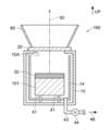
- FIG. 1 shows a radiant cooling device which is an example of a radiant cooling device according to the present disclosure.
- the direction of the sky) is a schematic cross-sectional view conceptually showing a state of being arranged outdoors.
- the radiant cooling device 100 includes a vacuum heat insulating container 10.
- the vacuum heat insulating container 10 is a container for accommodating the object to be cooled 101 therein and thermally insulating the object to be cooled 101 from the outside.
- An opening 10 ⁇ / b> A is provided on the upper surface of the vacuum heat insulating container 10.
- the vacuum heat insulating container 10 is connected to one end of a pipe 43 provided with a valve 44.
- a vacuum pump (not shown) is connected to the other end of the pipe 43.
- the inside of the vacuum heat insulating container 10 can be evacuated (ie, evacuated) by operating the vacuum pump and opening the valve 44.
- vacuum (state) means a state where the pressure is lower than the atmospheric pressure.
- the specific degree of vacuum inside the vacuum heat insulating container 10 is not particularly limited.
- the inside of the vacuum heat insulating container 10 The degree of vacuum preferably corresponds to at least one of the following inequality (1) and 100 Pa or less (preferably 10 Pa or less).
- the radiant cooling device 100 includes a far-infrared transmitting window member 20 that closes the opening 10 ⁇ / b> A of the vacuum heat insulating container 10.
- the far-infrared transmitting window member 20 has a function of transmitting a specific far-infrared ray 50 emitted from a far-infrared radiator 30 described later.
- the far-infrared transmitting window member 20 is a member that covers the opening 10 ⁇ / b> A of the vacuum heat insulating container 10, but the far-infrared transmitting window member is not limited to the form of the far-infrared transmitting window member 20.
- the far-infrared transmission window member may be a member that is fitted into the opening of the vacuum heat insulating container.
- the radiant cooling device 100 includes a far-infrared radiator 30 in the vacuum heat insulating container 10.
- the far-infrared radiator 30 has a function of emitting the specific far-infrared ray 50.
- the far-infrared radiator 30 is in thermal contact with the object to be cooled 101.
- the far-infrared radiator 30 is in thermal contact with the object 101 to be cooled.
- the far-infrared radiator 30 is in direct contact with the object 101 or a thermally conductive member (for example, metal). Means contact via a member.
- the far-infrared radiator 30 is not necessarily fixedly disposed in the vacuum heat insulating container 10.
- the object to be cooled 101 is accommodated in the vacuum heat insulating container 10, it may be simply placed on the object to be cooled 101 directly or via a heat conductive member.
- a plurality of support pins 41 are provided on the bottom surface in the vacuum heat insulating container 10 as support members for supporting the cooled object 101.
- the cooled object 101 is supported by a plurality of support pins 41.
- heat conduction from the bottom of the vacuum heat insulating container 10 to the cooled object 101 is further suppressed, and more effective vacuum heat insulation is realized.
- Examples of the material of the plurality of support pins 41 include metals (for example, steel), ceramics, resins, and the like.
- the shape of each of the plurality of support pins 41 is not particularly limited.
- each of the plurality of support pins 41 examples include a cylindrical shape, a conical shape, a prismatic shape, a pyramid shape, and a screw shape.
- the support member for supporting the cooled object 101 may be provided on the side surface in the vacuum heat insulating container 10 in place of the bottom surface in the vacuum heat insulating container 10 or in addition to the bottom surface in the vacuum heat insulating container 10. Good.
- the support member may be a member that reduces the contact area between the inner wall surface of the vacuum heat insulating container 10 and the cooled object 101 and the far-infrared radiator 30.
- the support member for supporting the to-be-cooled body 101 is not an essential member, and can also be abbreviate
- heat insulation means that heat conduction is suppressed, and there is no particular limitation on the specific heat conductivity.
- the thermal conductivity of “heat insulation” in the present disclosure is preferably less than 0.1 W / (m ⁇ K), and more preferably 0.08 W / (m ⁇ K) or less.
- the radiant cooling device 100 is disposed between the inner wall surface of the vacuum heat insulating container 10, the far-infrared radiator 30 and the cooled object 101, and far infrared rays having a wavelength range of 5 ⁇ m to 25 ⁇ m are emitted from the inner wall surface.
- an internal far-infrared reflecting film 14 for reflecting far-infrared rays in the wavelength range of 5 ⁇ m to 25 ⁇ m radiated from the inner wall surface is provided.
- the internal far-infrared reflective film 14 is disposed along the inner wall surface of the vacuum heat insulating container 10.
- the internal far-infrared reflective film 14 may be in contact with at least a part of the inner wall surface of the vacuum heat insulating container 10 or may not be in contact therewith.
- the internal far-infrared reflective film 14 is not an essential member and may be omitted.
- the object to be cooled is cooled by the radiant cooling device 100, first, the object to be cooled 101 is accommodated in the vacuum heat insulating container 10, and then the far infrared radiator 30 is thermally applied to the object to be cooled 101 in the vacuum heat insulating container 10. Make contact. Next, the opening 10 ⁇ / b> A of the vacuum heat insulating container 10 is covered and fixed with the far infrared ray transmitting window member 20, thereby closing the opening 10 ⁇ / b> A.
- the inside of the vacuum heat insulating container 10 is evacuated through the pipe 43 until a desired degree of vacuum (for example, 100 Pa or less) is reached (see the evacuation direction 46 in FIG. 1).
- a desired degree of vacuum for example, 100 Pa or less
- the specific far-infrared ray 50 radiated from the far-infrared radiator 30 that is in thermal contact with the cooled object 101 is a far-infrared transmitting window member. 20 is emitted to the outside of the radiant cooling device 100.
- the specific far-infrared ray 50 emitted to the outside of the radiation cooling apparatus 100 passes through the atmosphere without being absorbed by the atmosphere and reaches the sky (that is, outer space).
- the cooled object 101 is cooled by the radiation cooling phenomenon.
- the far-infrared radiator 30 and the cooled object 101 are accommodated in the vacuum heat insulating container 10 and are vacuum insulated from the outside of the vacuum heat insulating container 10.
- the fall of the radiation cooling performance resulting from the heat conduction (namely, heat inflow) from the outside of the vacuum heat insulation container 10 is suppressed.
- the far-infrared radiator and the object to be cooled are not accommodated in the container, and the far-infrared radiator and the object to be cooled are accommodated in the container. Therefore, the radiation cooling performance is improved as compared with the case where the vacuum insulation is not performed.
- the radiant cooling device 100 includes the internal far-infrared reflective film 14 inside the vacuum heat insulating container 10, even when far infrared rays having a wavelength range of 5 ⁇ m to 25 ⁇ m are radiated from the inner wall surface of the vacuum heat insulating container 10.
- the far-infrared radiation to the far-infrared radiator 30 and the cooled object 101 can be suppressed. For this reason, radiation cooling performance improves more.
- the arrangement angle of the entire radiant cooling device 100 is such that the opening 10 ⁇ / b> A of the vacuum heat insulating container 10 faces directly above (that is, the direction opposite to the direction of gravity).
- the arrangement angle is not limited to this angle.
- the arrangement angle of the entire radiant cooling device 100 may be an arrangement in which the opening of the vacuum heat insulating container faces obliquely upward.
- the arrangement angle of the entire radiation cooling device 100 may be an angle at which the specific far-infrared ray 50 emitted from the far-infrared radiator 30 is emitted toward the sky via the far-infrared transmitting window member 20.
- the arrangement angle of the entire radiant cooling device 100 is preferably an arrangement angle in which the opening of the vacuum heat insulating container faces a direction different from the direction of the sun.
- any object can be appropriately selected and used as the object to be cooled, and is not particularly limited.
- the object to be cooled is preferably a solid such as a resin body or a metal body in view of the principle of the radiant cooling device of the present disclosure using vacuum heat insulation.
- liquids such as water or gases such as water vapor can also be cooled by accommodating them in a vacuum heat insulating container in a state of being confined in the container.
- an object to be cooled (ice, resin body, metal body, etc.) that is solid may be confined in a container and accommodated in a vacuum heat insulating container.
- An arbitrary material can be appropriately selected and used as the container for confining the object to be cooled, and is not particularly limited.
- sealing a to-be-cooled body is the same as the specific example of the material of the vacuum heat insulation container mentioned later, A preferable aspect is also the same.
- the radiant cooling device of the present disclosure includes a vacuum heat insulating container (for example, the above-described vacuum heat insulating container 10).
- a vacuum heat insulation container is a container for accommodating a to-be-cooled body inside the vacuum heat-insulated container, and for vacuum-insulating the housed object to be cooled from the outside of the vacuum heat-insulated container.
- the vacuum heat insulation container is not particularly limited as long as it can exhibit the above-described function. Further, the vacuum insulation container does not need to maintain a vacuum at all times, and the inside of the vacuum insulation container may be at normal pressure during storage or transportation.
- the vacuum insulation can be achieved by connecting the vacuum insulation container to, for example, a vacuum pump.
- the vacuum heat insulating container has a strength that can withstand the generation of a necessary vacuum at least when the object to be cooled is cooled.
- the material of the container body of the vacuum insulation container there is no particular limitation on the material of the container body of the vacuum insulation container.
- a metal material or an inorganic material other than the metal material is preferable.
- the metal material include metals such as copper, silver, and aluminum; alloys such as stainless steel and aluminum alloys;
- the inorganic material other than the metal material include glass such as soda glass, potash glass, and lead glass; ceramics such as PLZT (lead lanthanum zirconate titanate titanate); quartz; fluorite; sapphire;
- a metal material having high performance of reflecting sunlight or radiant heat which is a main heat inflow source is preferable, and aluminum, silver, an aluminum alloy, or Stainless steel is more preferred.
- the material by which the metal material was coated with respect to inorganic materials other than a metal material may be sufficient.
- the thickness of the vacuum heat insulating container can be appropriately set in consideration of the strength of the vacuum heat insulating container and the degree of heat insulation.
- the vacuum heat insulating container is provided with an opening (for example, the above-described opening 10A).
- the opening part in a vacuum heat insulation container functions as an exit of the specific far infrared ray radiated
- the specific far-infrared ray emitted outside the vacuum heat insulating container through the opening passes through a far-infrared transmitting window member, which will be described later, which closes the opening, and further passes through the atmosphere and reaches the sky.
- planar shape of the opening examples include an elliptical shape (including a circular shape), a rectangular shape (including a square shape), and a polygonal shape other than a rectangular shape.
- the shape of the opening in plan view may be an indefinite shape other than these shapes. From the viewpoint of ease of processing, the shape of the opening in plan view is preferably an elliptical shape, and more preferably a circular shape.
- the opening part in a vacuum heat insulation container may have a function as an entrance / exit of a to-be-cooled body.
- the inlet / outlet port of the to-be-cooled body may be provided in the vacuum heat insulating container separately from the opening.
- you may comprise a vacuum heat insulation container so that a to-be-cooled body can be put in a vacuum heat insulation container, or can be taken out from a vacuum heat insulation container.
- the object to be cooled may not be accommodated in the vacuum heat insulating container except when the object to be cooled is cooled. It can be said that a vacuum heat insulation container has a to-be-cooled body accommodating part.
- the cooled object may be housed and taken out from the cooled object housing portion, or may be fixed to the cooled body housing portion.
- a body-to-be-cooled body accommodating part may be a space provided with some support structure around it, for example, an internal space of some container.
- a vacuum heat insulating container provided with an opening, provided with a cooled object accommodating portion therein, and configured to be thermally insulated from the outside when the inside is decompressed; Arranged between the object to be cooled and the opening in the vacuum insulation container and configured to be thermally insulated from the outside of the vacuum insulation container when the inside of the vacuum insulation container is depressurized.
- a far-infrared radiator that is in thermal contact with the part and emits far-infrared rays in the wavelength range of 8 ⁇ m to 13 ⁇ m;
- a far-infrared transmitting window member that closes the opening of the vacuum insulation container and transmits the far-infrared radiation emitted from the far-infrared radiator;
- a radiant cooling device comprising: Is provided.
- the reduced pressure may be, for example, reduced pressure to a vacuum degree of 1.0 ⁇ 10 ⁇ 9 Pa to 100 Pa, or reduced pressure to a vacuum degree of 1.0 ⁇ 10 ⁇ 5 Pa to 10 Pa. .
- Such a radiation cooling device can be used to cool a member to be cooled by disposing the object to be cooled in the object to be cooled and reducing the pressure inside the vacuum heat insulating container using a vacuum pump or the like. . For this reason, use of the radiant cooling device in cooling an object to be cooled is also provided.
- a container having a container wall and an opening, including a to-be-cooled body accommodating portion at a position separated from the container wall inside, and having a strength that can withstand pressure reduction to 100 Pa or less;
- a far-infrared radiator that emits far-infrared rays in the wavelength range of 8 ⁇ m to 13 ⁇ m;
- a far-infrared transmitting window member configured to transmit the far-infrared rays when arranged to close the opening of the container;
- the object to be cooled is placed in the object to be cooled housing, and the far-infrared radiator is in thermal contact with the object to be cooled and spaced from the container wall between the object to be cooled and the opening in the vacuum heat insulating container.
- a cooling kit is provided. Furthermore, use of such a cooling kit for cooling an object to be cooled is also provided.
- the height of the vacuum heat insulating container (that is, the length of the vacuum heat insulating container in the direction in which specific far infrared rays are emitted from the far infrared radiator) is, for example, 10 mm to 2 m, preferably 10 mm to 500 mm, more preferably 100 mm to 300 mm. It is.
- the maximum length of the vacuum heat insulating container (that is, the maximum length in the direction orthogonal to the height direction; for example, the diameter when the vacuum heat insulating container is cylindrical) is, for example, 10 mm to 30 m, preferably 10 mm to 1000 mm. More preferably, it is 100 mm to 500 mm.
- the maximum length of the opening of the vacuum heat insulating container (for example, the diameter when the opening is circular) is, for example, 10 mm to 30 m, preferably 10 mm to 1000 mm, more preferably 50 mm to 210 mm.
- a vacuum heat insulation container accommodates a to-be-cooled body and a far-infrared radiator, and vacuum-insulates these from the outside.
- 100 Pa or less is preferable from a viewpoint which improves radiation cooling performance more by suppressing the heat
- the lower limit of the degree of vacuum is not particularly limited, but is 1.0 ⁇ 10 ⁇ 9 Pa or more, or 1.0 ⁇ 10 ⁇ 5 Pa or more, or 1.0 ⁇ 10 ⁇ 1 Pa, for example, in terms of technical restrictions. It can be over.
- a degree of vacuum satisfying the following inequality (1) is also preferable from the viewpoint of further improving the radiation cooling performance by further suppressing the heat inflow to the object to be cooled and the far infrared radiator.
- P represents the degree of vacuum (Pa) in vacuum insulation
- ⁇ represents a value of 1.5 to 2.0
- k B represents a Boltzmann constant
- T represents a vacuum
- K the degree of vacuum
- d the diameter (m) of gas molecules in the vacuum heat insulation container
- L the shortest distance (m) between the vacuum heat insulation container and the object to be cooled.
- the inequality (1) indicates that the thermal conductivity of the gas G enclosed in the vacuum insulation container under atmospheric pressure is ⁇ (G, 0), and the degree of vacuum P of the gas G enclosed in the vacuum insulation container is P.
- the thermal conductivity at (Pa) is ⁇ (G)
- L is the shortest distance (m) between the vacuum heat insulating container and the object to be cooled
- L mean is the mean free path of the gas G at the degree of vacuum P (Pa) in the vacuum heat insulation
- L mean / L ratio Is K and ⁇ is a value of 1.5 to 2.0
- a dotted line is a curve when ⁇ is 1.5
- a solid line is a curve when ⁇ is 2.0.
- the inventors have experimentally determined that the region where the ratio ⁇ (G) / ⁇ (G, 0) is 0.90 or less (that is, ⁇ (G) / ⁇ (G , 0) in the region where the ratio is 0.90 or less), it has been found that the heat inflow to the cooled object and the far-infrared radiator is further suppressed, and the radiation cooling performance is further improved. This finding is shown by the following relational expression (F2).
- P represents the degree of vacuum (Pa) in the vacuum insulation
- k B represents the Boltzmann constant
- T represents the temperature (K) in the vacuum insulation container
- d is The diameter (m) of the gas molecule in a vacuum heat insulation container.
- inequality (1) is an example where ⁇ is 2.0 and d is 0.36 ⁇ 10 ⁇ 9 m.
- 0.36 ⁇ 10 ⁇ 9 m is the average diameter of molecules in the atmosphere (that is, nitrogen molecules and oxygen molecules).
- the radiant cooling device includes at least one support member (for example, the support pin 41 described above) for supporting the object to be cooled on the inner wall surface (that is, the bottom surface and / or the side surface) of the vacuum heat insulating container. Also good. As a result, the contact area between the inner wall surface of the vacuum heat insulating container and the object to be cooled can be reduced (or the inner wall surface of the vacuum heat insulating container and the object to be cooled cannot be contacted). Heat conduction from the inner wall surface to the object to be cooled is further suppressed.
- the material for the support member include metals (steel etc.), ceramics, resins and the like.
- the resin examples include acrylic resin, phenol resin, epoxy resin, ABS resin (acrylonitrile / butadiene / styrene copolymer resin) and the like. Among these, a phenol resin is preferable from the viewpoint of low thermal conductivity.
- the shape of the support member is not particularly limited, and examples of the shape of the support member include a columnar shape, a conical shape, a prismatic shape, a pyramid shape, a spherical shape, and a plate shape.
- the radiant cooling device of the present disclosure is not limited to including a support member for supporting the object to be cooled.
- a repulsive force such as magnetic force
- the object to be cooled is floated from the bottom surface of the vacuum heat insulating container, and the inner wall surface of the vacuum heat insulating container and the object to be cooled are not in contact with each other.
- the effect of can be obtained.
- the aspect which floats a to-be-cooled body with a magnetic force is realizable by providing magnetic materials, such as a magnet, in the bottom face of a vacuum heat insulation container.
- the effect similar to the case where a support member is provided can be acquired by providing the below-mentioned internal heat insulation layer.
- the radiation cooling device of the present disclosure may be provided along at least a part of the inner wall surface of the vacuum heat insulating container, and may include an inner heat insulating layer for insulating the inner wall surface of the vacuum heat insulating container and the object to be cooled.
- “Inside” in the internal heat insulating layer means the inside of the vacuum heat insulating container.
- the internal heat insulating layer may function as a support member for supporting the object to be cooled.
- the heat insulating material for forming the internal heat insulating layer any material can be appropriately selected and used, and is not particularly limited.
- the heat insulating material forming the internal heat insulating layer include resin materials having air bubbles, such as silica airgel, polystyrene foam, glass wool, and bubble buffer materials.
- foam cushioning materials include Air Cap (registered trademark) (Sakai Chemical Industry Co., Ltd.), Petit Petit (registered trademark) (Kawakami Sangyo Co., Ltd.), Minapak (registered trademark) (Sakai Chemical Industry Co., Ltd.), etc. Can be mentioned.
- the radiant cooling device of the present disclosure is further disposed at least between the inner wall surface (that is, the side surface and / or the bottom surface) of the vacuum heat insulating container and the object to be cooled, and far infrared rays having a wavelength range of 5 ⁇ m to 25 ⁇ m from the inner wall surface.
- An internal far-infrared reflective film (for example, the above-described internal far-infrared reflective film 14) that reflects far infrared rays having a wavelength range of 5 ⁇ m to 25 ⁇ m emitted from the inner wall surface when radiated may be provided.
- the internal far-infrared reflective film can be disposed along at least a part of the inner wall surface of the vacuum heat insulating container, for example.
- the internal far-infrared reflective film may be in contact with at least a part of the inner wall surface of the vacuum heat insulating container or may not be in contact with it.
- the internal far-infrared reflective film is preferably disposed between the inner wall surface of the vacuum heat insulating container and the cooled object and the far-infrared radiator.
- the radiation cooling device of the present disclosure includes an internal far-infrared reflective film, even when far-infrared rays having a wavelength range of 5 ⁇ m to 25 ⁇ m are radiated from the inner wall surface of the vacuum heat insulating container, the vacuum heat insulating container is directed to the object to be cooled. Since far-infrared radiation (ie, thermal radiation) can be suppressed, radiation cooling performance is further enhanced.
- far-infrared radiation ie, thermal radiation
- the internal far-infrared reflective film has an average reflectance R 5-25 in the wavelength region of 5 ⁇ m to 25 ⁇ m of preferably 0.40 or more, more preferably 0.60 or more, and 0.80 or more. It is particularly preferred.
- the average reflectance R 5-25 means an arithmetic average value of spectral reflectances at wavelengths included in the wavelength range of 5 ⁇ m to 25 ⁇ m in Appendix Table 3 of JIS R 3106: 1998.
- the average reflectance R 5-25 is measured except that the spectral reflectance at a wavelength included in the wavelength range of 5 ⁇ m to 25 ⁇ m is measured in Table 3 of JIS R 3106: 1998, and the arithmetic average of the measurement results is obtained. This is the same as the method for measuring the average emissivity E 5-25 described later.
- Examples of the material for the internal far-infrared reflective film include aluminum, aluminum alloy, silver, silver alloy, copper, and copper alloy.
- the radiant cooling device of the present disclosure may include an external sunlight reflecting film that reflects sunlight on the outer side of at least a part of the outer wall surface of the vacuum heat insulating container.
- the “outside” in the external sunlight reflecting film means the outside of the vacuum heat insulating container.
- a layer similar to the sunlight reflecting layer preferably a sunlight reflecting layer that is a resin layer containing air bubbles
- the radiant cooling device of the present disclosure includes a far-infrared radiator (for example, the above-described far-infrared radiator 30) that emits specific far-infrared rays in a vacuum heat insulating container.
- a far-infrared radiator for example, the above-described far-infrared radiator 30
- the far-infrared radiator is disposed between the object to be cooled and the opening of the vacuum heat insulating container and is in thermal contact with the object to be cooled.
- radiating specific far infrared rays means that the average emissivity E 8-13 in the wavelength range of 8 ⁇ m to 13 ⁇ m in the direction of emitting specific far infrared rays is 0.40 or more.
- the direction in which the specific far infrared ray is emitted is the direction in which the specific far infrared ray emitted from the far infrared radiator is emitted from the vacuum heat insulating container to the outside through the far infrared ray transmission window member. For example, in FIGS. This is the direction indicated as the traveling direction of the specific far infrared ray 50.
- the position of the far-infrared radiator in the vacuum insulation container is such that, when the opening of the vacuum insulation container is viewed from the outside of the vacuum insulation container, at least a part of the opening and at least a part of the far-infrared radiator overlap.
- the position is preferable, and the position where the entire opening and at least a part of the far-infrared radiator overlap is more preferable.
- the structure of the far-infrared radiator may be a single-layer structure including the radiator body, or may be a laminated structure including the radiator body and other layers (for example, a radiator reflecting layer described later). .
- the far-infrared radiator preferably has an average emissivity E 8-13 in the wavelength range of 8 ⁇ m to 13 ⁇ m in the direction of emitting specific far-infrared rays, preferably 0.80 or more, and more preferably 0.85 or more. 0.90 or more is particularly preferable.
- the average emissivity E 8-13 of the far-infrared radiator is 0.80 or more, the radiation performance of the specific far-infrared radiation of the far-infrared radiator is further improved, so that the temperature reached during cooling can be further lowered. .
- the average emissivity E 8-13 of the far-infrared transmitting window member is preferably 0.98 or less from the viewpoint of suitability for manufacturing the far-infrared transmitting window member.
- the preferable spectral characteristics (average emissivity) of the far-infrared radiator is, when the far-infrared radiator has a laminated structure, the spectrum of the entire far-infrared radiator (that is, the entire laminated structure). Means a characteristic.
- the average emissivity E 8-13 is determined by Kirchhoff's law at each of the wavelengths (the 10 wavelengths described above) included in the wavelength range of 8 ⁇ m to 13 ⁇ m in Appendix 3 of JIS R 3106: 1998. It means a value obtained by calculating the spectral emissivity from the spectral transmittance and the spectral reflectance and arithmetically averaging the obtained spectral emissivities. Specifically, the average emissivity in the wavelength range of 8 ⁇ m to 13 ⁇ m is obtained as follows. First, spectral transmittance and spectral reflectance in a wavelength range of 1.7 ⁇ m to 25 ⁇ m are measured by Fourier transform infrared spectroscopy (FTIR).
- FTIR Fourier transform infrared spectroscopy
- wavelengths included in the wavelength range of 8 ⁇ m to 13 ⁇ m in Appendix 3 of JIS R 3106: 1998 specifically, 8. 10 wavelengths of 1 ⁇ m, 8.6 ⁇ m, 9.2 ⁇ m, 9.7 ⁇ m, 10.2 ⁇ m, 10.7 ⁇ m, 11.3 ⁇ m, 11.8 ⁇ m, 12.4 ⁇ m, and 12.9 ⁇ m.
- Spectral emissivity is calculated from Kirchhoff's law.
- Spectral emissivity 1-Spectral transmittance-Spectral reflectivity "Average emissivity in the wavelength range of 8 ⁇ m to 13 ⁇ m" is obtained by arithmetically averaging the spectral emissivities (10 values) of each wavelength. .
- FTIR manufactured by Varian (model number: FTS-7000) was used as the FTIR apparatus.
- the far-infrared radiator preferably emits the specific far-infrared preferentially (ideally selectively) in the direction in which the specific far-infrared is radiated.
- the far infrared radiator is the ratio of the average emissivity E 8-13 to the average emissivity E 5-25 in the wavelength range of directions of 5 [mu] m ⁇ 25 [mu] m for emitting a specific far infrared E 8-13
- the / E 5-25 ratio is preferably 1.20 or more, more preferably 1.30 or more, and particularly preferably 1.50 or more.
- the E 8-13 / E 5-25 ratio of the far-infrared radiator is 1.20 or more, far-infrared radiation by atmospheric thermal radiation (that is, thermal radiation by an electromagnetic wave having a wavelength of less than 8 ⁇ m and an electromagnetic wave having a wavelength of more than 13 ⁇ m)
- a specific far-infrared ray can be emitted from the far-infrared radiator while suppressing heat inflow to the body. Accordingly, it is possible to lower the temperature reached during cooling.
- the E 8-13 / E 5-25 ratio is preferably 2.40 or less.
- the average emissivity E 5-25 means an arithmetic average value of spectral emissivities at wavelengths included in the wavelength range of 5 ⁇ m to 25 ⁇ m in Appendix 3 of JIS R 3106: 1998. Specifically, the average emissivity E 5-25 is obtained as follows. First, spectral transmittance and spectral reflectance in the wavelength range of 1.7 ⁇ m to 25 ⁇ m are measured by Fourier transform infrared spectroscopy (FTIR).
- FTIR Fourier transform infrared spectroscopy
- the spectral emissivity is calculated from Kirchhoff's law described above.
- the average emissivity E 5-25 is obtained by arithmetically averaging the spectral emissivities (24 values) of each wavelength.
- the average reflectance R 3-7 in the wavelength range of 3 ⁇ m to 7 ⁇ m of the surface on the far-infrared radiation window member side is preferably 0.05 or more, and preferably 0.10 or more. More preferred.
- the average reflectance R 3-7 of the far-infrared transmitting window member is 0.10 or more, the distance from the far-infrared radiator and the object to be cooled (the direction of the far-infrared transmitting window member when viewed from the far-infrared radiator) is Since it is possible to suppress the incidence of electromagnetic waves in the wavelength range of 3 ⁇ m to 7 ⁇ m, it is possible to further suppress the increase in the ultimate temperature due to the incidence of such electromagnetic waves.
- the average reflectance R 3-7 of 0.05 or more is more easily achieved when the far-infrared radiator includes a radiator reflecting layer described later. There is no particular upper limit on the average reflectance R 3-7 of the far-infrared transmitting window member. From the viewpoint of suitability for manufacturing the far-infrared transmitting window member, the average reflectance R 3-7 of the far-infrared transmitting window member is preferably 0.90 or less (more preferably 0.80 or less).
- the average reflectance R 3-7 means an arithmetic average value of spectral reflectances at wavelengths included in the wavelength range of 3 ⁇ m to 7 ⁇ m in Appendix Table 3 of JIS R 3106: 1998.
- the average reflectance R 3-7 is measured except that the spectral reflectance at a wavelength included in the wavelength range of 3 ⁇ m to 7 ⁇ m is measured in Table 3 of JIS R 3106: 1998, and the arithmetic average of the measurement results is obtained. This is the same as the method for measuring the average emissivity E 8-13 described above.
- a far-infrared radiator As a far-infrared radiator (radiator body), a substance that emits a specific far-infrared ray can be appropriately selected from known thermal radiators, and is not particularly limited.
- a black body radiator or a radiator including a laminated film of a titania film and a silica film is preferable in that the average emissivity in the wavelength range of 8 ⁇ m to 13 ⁇ m is high.
- a black-body radiator is preferable from the viewpoint of manufacturability.
- Blackbody radiators include blackbody radiators that are black bodies themselves, blackbody radiators that have a commercially available blackbody spray applied to the surface of a metal material, and black bodies that have a commercially available blackbody tape attached to the surface of a metal material. And radiators.
- the far-infrared radiator Radiator body
- E 8-13 / E 5-25 ratio e.g., E 8-13 / E 5-25 ratio is 1.20 or more
- a radiator including a laminated film of a titania film and a silica film is preferable.
- the three-dimensional shape of the entire far-infrared radiator is not particularly limited, but is preferably a plate shape from the viewpoint of making the apparatus compact.
- plan view shape of the entire far-infrared radiator There is no particular limitation on the plan view shape of the entire far-infrared radiator.
- Examples of the shape of the far-infrared radiator in plan view include an elliptical shape (including a circular shape), a rectangular shape (including a square shape), and a polygonal shape other than a rectangular shape.
- the shape of the far-infrared radiator in plan view may be an indefinite shape other than these shapes.
- the planar shape of the entire far-infrared radiator is preferably an elliptical shape, particularly preferably a circular shape, from the viewpoint of availability.
- the thickness of the entire far-infrared radiator is preferably 1 mm to 30 mm, more preferably 1 mm to 20 mm, and particularly preferably 2 mm to 10 mm.
- the thickness of the entire far-infrared radiator is 1 mm or more, it is advantageous in terms of the strength of the far-infrared radiator.
- the thickness of the far-infrared radiator is 30 mm or less, it is advantageous in terms of space saving in the heat insulating container.
- the far-infrared radiator can include a radiator body and a radiator reflecting layer that is disposed on the far-infrared radiation window member side as viewed from the radiator body and reflects electromagnetic waves in a wavelength region of 3 ⁇ m to 7 ⁇ m.
- the far-infrared radiator includes the radiator reflecting layer, the wavelength region of 3 ⁇ m to 7 ⁇ m from above the radiator body and the cooled object (in the direction of the far-infrared radiation window member when viewed from the far-infrared radiator). Since the incidence of electromagnetic waves can be suppressed, an increase in the arrival temperature due to the incidence of such electromagnetic waves can be further suppressed.
- the preferable aspect of a radiator reflective layer is the same as the preferable aspect of the below-mentioned sunlight reflective layer. According to the aspect in which the far-infrared radiator includes the radiator reflecting layer, it is easier to achieve that the average reflectance R 3-7 of the far-infrared radiator is 0.05 or more.
- the radiant cooling device of the present disclosure closes the opening of a vacuum heat insulating container and transmits a far-infrared transmitting window member that transmits a specific far-infrared ray (that is, a far-infrared ray having a wavelength range of 8 ⁇ m to 13 ⁇ m) (for example, the aforementioned far-infrared transmitting member).
- a window member 20 The radiant cooling device of the present disclosure closes the opening of a vacuum heat insulating container and transmits a far-infrared transmitting window member that transmits a specific far-infrared ray (that is, a far-infrared ray having a wavelength range of 8 ⁇ m to 13 ⁇ m) (for example, the aforementioned far-infrared transmitting member).
- the structure of the far-infrared transmitting window member may be a single-layer structure including a window member main body, or may be a laminated structure including a window member main body and other layers (for example, a solar reflective layer described later). Good.
- the far-infrared transmission window member preferably has an average transmittance T 8-13 in the wavelength range of 8 ⁇ m to 13 ⁇ m in the direction of transmitting the specific far-infrared ray is 0.40 or more, more preferably 0.50 or more. Preferably, it is 0.60 or more.
- the direction of transmitting the specific far-infrared is the direction in which the specific far-infrared emitted from the far-infrared radiator is emitted from the vacuum heat insulating container to the outside through the far-infrared transmitting window member. For example, in FIGS.
- the average transmittance T 8-13 of the far-infrared transmitting window member is 0.40 or more, the specific far-infrared ray radiated from the far-infrared radiator is more easily transmitted through the far-infrared transmitting window member. The reached temperature can be further lowered.
- the upper limit of the average transmittance T 8-13 of the far infrared ray transmitting window member is no particular limitation on the upper limit of the average transmittance T 8-13 of the far infrared ray transmitting window member. From the viewpoint of suitability for manufacturing the far-infrared transmitting window member, the average transmittance T 8-13 of the far-infrared transmitting window member is preferably 0.98 or less.
- preferable spectral characteristics (average transmittance and solar reflectance) of the far-infrared transmitting window member are the entire far-infrared transmitting window member when the far-infrared transmitting window member has a laminated structure ( That is, it means the spectral characteristics of the entire laminated structure).
- the average transmittance T 8-13 means an arithmetic average value of spectral transmittances at wavelengths included in the wavelength range of 8 ⁇ m to 13 ⁇ m in Appendix Table 3 of JIS R 3106: 1998.
- the average transmittance T 8-13 is obtained as follows. First, spectral transmittance in the wavelength range of 1.7 ⁇ m to 25 ⁇ m is measured by Fourier transform infrared spectroscopy (FTIR). Among the measurement results of the spectral transmittance in the wavelength range of 1.7 ⁇ m to 25 ⁇ m, the spectrum at the wavelengths (the aforementioned 10 wavelengths) included in the wavelength range of 8 ⁇ m to 13 ⁇ m in Appendix 3 of JIS R 3106: 1998. The average transmittance T 8-13 is obtained by arithmetically averaging the transmittance values (that is, 10 values).
- the far-infrared transmitting window member preferably transmits the specific far-infrared light preferentially (ideally selectively) in the direction in which the specific far-infrared light is transmitted.
- the far-infrared transmitting window member has a ratio T 8 ⁇ that is the ratio of the average transmittance T 8-13 to the average transmittance T 5-25 in the wavelength range of 5 ⁇ m to 25 ⁇ m in the direction of transmitting the specific far infrared rays.
- the 13 / T 5-25 ratio is preferably 1.20 or more, more preferably 1.30 or more, and particularly preferably 1.50 or more.
- the T 8-13 / T 5-25 ratio of the far-infrared transmitting window member is 1.20 or more, radiation cooling by atmospheric thermal radiation (that is, thermal radiation by an electromagnetic wave having a wavelength of less than 8 ⁇ m and an electromagnetic wave having a wavelength of more than 13 ⁇ m)
- the specific far-infrared ray from the far-infrared radiator can be transmitted while suppressing the heat inflow into the apparatus. Accordingly, it is possible to lower the temperature reached during cooling.
- the T 8-13 / T 5-25 ratio is preferably 2.40 or less.
- the average transmittance T 5-25 means an arithmetic average value of spectral transmittances at wavelengths included in the wavelength range of 5 ⁇ m to 25 ⁇ m in Appendix Table 3 of JIS R 3106: 1998. Specifically, the average transmittance T 5-25 is determined as follows. First, spectral transmittance in the wavelength range of 1.7 ⁇ m to 25 ⁇ m is measured by Fourier transform infrared spectroscopy (FTIR). Among the measurement results of the spectral transmittance in the wavelength range of 1.7 ⁇ m to 25 ⁇ m, the wavelengths included in the wavelength range of 5 ⁇ m to 25 ⁇ m in Appendix Table 3 of JIS R 3106: 1998 (that is, the aforementioned 24 wavelengths). The average transmittance T 5-25 is obtained by arithmetically averaging the spectral transmittance values (ie, 24 values).
- FTIR Fourier transform infrared spectroscopy
- the far-infrared transmitting window member preferably has a solar reflectance of 60% or more on the surface opposite to the surface on the far-infrared radiator side.
- the solar radiation reflectance of the far-infrared transmitting window member is 60% or more, it is possible to suppress the incidence of sunlight (that is, electromagnetic waves having a wavelength range of 300 nm to 2500 nm) into the heat insulating container. Heat inflow can be suppressed. Accordingly, it is possible to lower the temperature reached during cooling.
- the solar reflectance of the far infrared ray transmitting window member is more preferably 70% or more, and particularly preferably 80% or more.
- the solar reflectance of the far-infrared transmitting window member is preferably 98% or less. It is easy to achieve that the far-infrared transmission window member has a solar reflectance of 60% or more when the far-infrared transmission window member includes a solar light reflection layer described later.
- the solar reflectance refers to a value calculated based on the diffuse reflectance obtained by measuring the diffuse reflectance with a spectrophotometer in accordance with JIS A 5759: 2008.
- a spectrophotometer is used as the spectrophotometer.
- a spectrophotometer V-670 integrated sphere spectrophotometer manufactured by JASCO Corporation was used as a spectrophotometer used for measurement of solar reflectance.
- the material of the far infrared ray transmitting window member (window member main body) is not particularly limited as long as it is a material that can transmit the specific far infrared ray.
- Examples of the material of the far-infrared transmission window member (window member main body) include metal materials, inorganic materials other than metal materials, and more specifically, germanium (Ge; transmission wavelength: 1.8 ⁇ m to 23 ⁇ m), chalcogenide (Transmission wavelength: 0.75 ⁇ m to 14 ⁇ m), silicon (Si; transmission wavelength: 1.2 ⁇ m to 15 ⁇ m), diamond (transmission wavelength: 220 nm or more), calcium fluoride (CaF 2 ; transmission wavelength: 0.12 ⁇ m to 12 ⁇ m), zinc selenium (ZnSe) Transmission wavelength 0.5 ⁇ m to 22 ⁇ m), barium fluoride (BaF 2 ; transmission wavelength 0.15 ⁇ m to 15 ⁇ m), zinc sulfide (ZnS; transmission
- the three-dimensional shape of the entire far-infrared transmitting window member is preferably a plate shape.
- the shape of the far-infrared transmitting window member in plan view.
- Examples of the planar shape of the entire far-infrared transmitting window member include an elliptical shape (including a circular shape), a rectangular shape (including a square shape), and a polygonal shape other than a rectangular shape.
- the far-infrared transmission window member may have an indefinite shape other than these shapes in plan view.
- the thickness of the entire far-infrared transmitting window member is preferably 1 mm to 30 mm, more preferably 1 mm to 20 mm, and particularly preferably 2 mm to 10 mm.
- the thickness is 1 mm or more, the penetration of electromagnetic waves other than the specific far-infrared ray into the heat insulating container can be further suppressed, and the strength of the far-infrared transmitting window member is advantageous.
- the thickness is 30 mm or less, the transmittance of the specific far infrared ray is further improved.
- the far-infrared transmissive window member can include a window member main body and a sunlight reflecting layer that is disposed on the side opposite to the far-infrared radiator side when viewed from the window member main body and reflects sunlight.
- the far-infrared transmitting window member includes the sunlight reflecting layer, it is possible to suppress the incidence of sunlight (that is, electromagnetic waves having a wavelength range of 0.3 ⁇ m to 2.5 ⁇ m) into the heat insulating container. Heat inflow can be suppressed. Accordingly, it is possible to lower the temperature reached during cooling.
- the solar reflectance of the far-infrared transmitting window member is 60% or more (preferably 70% or more, more preferably 80% or more. Is easier to achieve).
- the sunlight reflecting layer has a function of reflecting sunlight, but may have a function of reflecting electromagnetic waves other than sunlight (for example, electromagnetic waves having a wavelength of more than 2.5 ⁇ m and less than 8 ⁇ m).
- the structure of the sunlight reflecting layer may be a single layer structure or a laminated structure.
- the laminated structure is preferably a laminated structure having at least one layer selected from the group consisting of a metal layer, an inorganic layer, and an organic layer.
- the structure of the sunlight reflecting layer may be a structure including a minute structure (particles, bubbles, etc.), or may be a structure having an uneven structure on the surface.
- Examples of the “micro structure” in the case where the structure of the sunlight reflecting layer includes a micro structure include particles, bubbles, and the like.
- a sunlight reflective layer is not limited to being a continuous layer, The particle layer which consists of the particle
- the solar reflective layer preferably contains particles.
- the number average particle diameter of the particles is preferably 0.1 ⁇ m to 20 ⁇ m.
- the scattering cross section for sunlight of the sunlight reflecting layer increases. Thereby, the solar radiation reflectance of the whole far-infrared transmission window member can be enlarged more.
- the scattering cross section for the specific far-infrared ray of the sunlight reflecting layer becomes small. Thereby, the transmittance
- the number average particle diameter of the particles means a value measured as follows. That is, the solar reflective layer is cut along the thickness direction using a microtome, and a cross-sectional image at a magnification of 1000 is obtained from the cut surface using an electron microscope S4100 (manufactured by Hitachi High-Technology Corporation). In the acquired cross-sectional image, in each particle, the maximum length among the line segments connecting the two points inside the particle is defined as the particle length. The measurement of the above particle length is performed about 100 places in a cross-sectional image, and let the average value of 100 measured values be the number average particle diameter of particles.
- substances constituting the particles include titanium oxide, barium titanate compound, zinc sulfide, barium oxide, magnesium oxide, calcium oxide, and the like.
- zinc sulfide is preferable in terms of excellent optical characteristics.
- the solar reflective layer may contain a resin.
- Specific examples of the resin are the same as the specific examples of the resin in the resin layer containing bubbles, which will be described later.
- the solar reflective layer is composed of particles dispersed in the window member main body (for example, the above-described zinc sulfide particles, oxidized particles, etc.) from the viewpoint of maintaining the transmission of specific far infrared rays as the entire far infrared transparent window member.
- a particle layer made of titanium particles or the like is preferable.
- the material other than the bubbles includes a resin. That is, as the sunlight reflecting layer, a sunlight reflecting layer that is a resin layer containing bubbles can also be used.
- the resin in the resin layer containing bubbles include polyolefin (for example, polyethylene, polypropylene, poly-4-methylpentene-1, polybutene-1, etc.), polyester (for example, polyethylene terephthalate, polyethylene naphthalate, etc.), polycarbonate, polyvinyl chloride.
- polyester is preferable from the viewpoint of excellent processability and optical characteristics, and polyethylene terephthalate (hereinafter also referred to as “PET”) is preferable.
- the resin layer containing bubbles may contain a mixture of two or more kinds of resins depending on the purpose. Moreover, the resin layer containing air bubbles may contain inevitable impurities as long as it does not affect the reflectance of sunlight.
- the bubble in the resin layer containing bubbles refers to a space made of a gas having a bubble length of 10 nm or more present in the resin.
- the bubble length refers to the maximum length of line segments connecting two points inside the bubble in each bubble.
- the bubble length is a value measured by the method described later.
- the type of gas may be air, or may be another type of gas other than air, such as oxygen, nitrogen, carbon dioxide.
- the shape of the bubble is not particularly limited, and examples thereof include various shapes such as a spherical shape, a cylindrical shape, an elliptical shape, a rectangular parallelepiped shape (cubic shape), and a prismatic shape.
- atmospheric pressure may be sufficient as the pressure of gas, and it may be pressurized or pressure-reduced rather than atmospheric pressure.
- Each of the bubbles may be present in isolation or may be partially connected.
- the number average length of the bubbles is preferably 0.1 ⁇ m to 20 ⁇ m.
- the scattering cross-sectional area of the sunlight reflecting layer with respect to sunlight increases. Thereby, the solar reflectance of a far-infrared transmissive window member can be enlarged more.
- the scattering cross section for the specific far infrared ray of the sunlight reflecting layer becomes small. Thereby, the transmittance
- the number average length of the bubbles means a value measured as follows. In the cross-sectional image obtained in the same manner as in the measurement of the number average particle diameter of the particles, the maximum length of the line segments connecting two points inside the bubbles is defined as the bubble length. The above bubble length measurement is performed for 100 bubbles in the cross-sectional image, and the average value of the 100 measured values is taken as the number average length of the bubbles.
- a commercially available resin film can also be used as a sunlight reflective layer which is a resin layer containing air bubbles.
- Commercially available resin films include ultra-fine foamed light reflector “MCPET / MCPOLYCA” manufactured by Furukawa Electric Co., Ltd., white PET films manufactured by Toray Industries, Inc., Lumirror (registered trademark) E20, E22, and E28G. And E60.
- a concavo-convex structure in the case where the structure of the sunlight reflecting layer has a concavo-convex structure on the surface, a concavo-convex structure having an average pitch of 100 ⁇ m or less is preferable.
- means for forming such a concavo-convex structure include nanoimprint and plasma etching.
- the radiation cooling device of this indication may be provided with the metal cylinder member which the specific far-infrared which permeate
- the radiation cooling device of this indication is provided with a metal cylinder member, the heat inflow into the vacuum heat insulation container by the heat radiation from surrounding environment members (for example, buildings, buildings, such as a utility pole) can be controlled. Therefore, the deterioration of the radiation cooling performance due to this heat inflow is further suppressed.
- cylinder is a concept including a tapered cylinder.
- a taper cylinder refers to a cylinder having a shape in which the diameter (outer diameter and inner diameter) increases from one axial end to the other.
- FIG. 3 is a schematic cross-sectional view of a radiant cooling device including a metal cylinder member, which is another example of the radiant cooling device of the present disclosure.
- the structure of the radiant cooling device 150 shown in FIG. 3 is the same as the structure of the radiant cooling device 100 shown in FIG. 1 except that the metal cylinder member 60 is provided.
- the radiant cooling device 150 includes a metal cylinder member 60 on the side opposite to the far-infrared radiator 30 side when viewed from the far-infrared transmitting window member 20.
- the metal cylinder member 60 has a tapered cylinder shape. Examples of the shape of the tapered cylinder include a linear tapered shape, a parabolic tapered shape, and an exponential tapered shape.
- the metal cylinder member 60 is disposed so that one end in the axial direction is in contact with the far-infrared transmitting window member 20 and the diameter increases in the direction from one end to the other end in the axial direction. Furthermore, the metal cylinder member 60 includes the opening 10A within a range surrounded by the inner peripheral surface on one end side of the metal cylinder member 60 in a plan view (not shown) viewed from the opening direction of the opening 10A.
- the radiant cooling device 150 heat from the surrounding environment member (for example, a building such as a building or a utility pole) is passed through the inside of the metal cylinder member 60 while the specific far infrared ray 50 that has passed through the far infrared ray transmission window member 20 is passed through. Radiation (specifically, far infrared rays radiated from the surrounding environment member) can be blocked by the outer peripheral surface of the metal cylinder member 60. Furthermore, since the metal cylinder member 60 is arranged in such a direction that the diameter increases as it goes from one end to the other end in the axial direction, the effective area from which the specific far-infrared ray 50 is emitted is larger than the area of the opening 10A. growing. For these reasons, the radiant cooling device 150 can provide better radiant cooling performance.
- the surrounding environment member for example, a building such as a building or a utility pole
- the opening area of the other end side in the axial direction of the metal cylinder member 60 (that is, the end portion far from the far-infrared transmitting window member 20) is from the viewpoint of increasing the effective area from which the specific far-infrared ray 50 is emitted.
- the area of the opening 10A is preferably 1.1 times or more, and more preferably 1.3 times or more.
- the opening area on the other end side in the axial direction of the metal cylinder member 60 is preferably 6.0 times or less with respect to the area of the opening 10A from the viewpoint of more effectively blocking heat radiation from the surrounding environment member. 0.0 times or less is more preferable.
- a metal having a high far-infrared reflectance is preferable, and specifically, aluminum, an aluminum alloy, silver, or a silver alloy is preferable.
- the metal cylinder member As the metal cylinder member, a commercially available parabolic mirror (for example, a parabolic mirror manufactured by Kokusai Shoji Co., Ltd.) may be used.
- the parabolic mirror parabolic mirror refers to a metal cylinder member having a parabolic taper shape.
- the radiant cooling device of the present disclosure includes the above-described metal cylinder member
- the radiant cooling device of the present disclosure has an angle at which the outer opening of the metal cylinder member (the end on the side far from the far-infrared transmitting window member) faces. You may provide the angle changing apparatus to change.
- the outer opening of the metal tube member refers to the opening at the end on the side far from the far-infrared transmitting window member.
- This angle changing device preferably has a function of directing the outer opening of the metal cylinder member in a direction different from the position of the sun. In order to realize such a function, any system can be appropriately selected and applied.
- the direct opening of the sun can be suppressed by directing the outer opening of the metal tube member in a direction different from the position of the sun, so that heat inflow due to this incident can be suppressed. Thereby, especially the rise of the ultimate temperature in the daytime can be suppressed more.
- Example 1 ⁇ Production of radiation cooling device>
- the radiant cooling device 100 shown in FIG. 1 was produced.
- a vacuum heat insulating container 10 made of SUS304 having a shape in which an opening 10A of ⁇ 140 mm was provided on the upper surface of an internal hollow cylindrical shape having an inner diameter ⁇ 200 mm, an outer diameter ⁇ 220 mm, and a height 168 mm was prepared.
- One end of a pipe 43 provided with a valve 44 is connected to the vacuum heat insulating container 10.
- a vacuum gauge (G-TRAN SW1 manufactured by ULVAC; not shown) for confirming the degree of vacuum in the vacuum heat insulating container 10 and a vacuum pump (ULVAC for evacuating the vacuum heat insulating container 10) GVD-136 (not shown) was connected in series in this order from the other end side.
- the degree of vacuum in the vacuum heat insulating container 10 is determined by measuring the voltage of the vacuum gauge with a high-performance recorder (GR-3500 manufactured by KEYENCE) and converting the numerical value to the degree of vacuum. Asked.
- Three support pins 41 for supporting the object to be cooled are arranged on the bottom surface in the vacuum heat insulating container 10.
- hexagon socket set screws MSST6-25 manufactured by MISUMI Corporation, length 25 mm, ⁇ 6 mm were used.
- the vacuum heat insulating container 10 a commercially available aluminum foil (manufactured by Mitsubishi Aluminum Co., Ltd.) as the internal far-infrared reflective film 14 was disposed along the inner wall surface of the vacuum heat insulating container 10.
- a plate made of stainless steel (SUS304) having a heat capacity of 1500 J / K, ⁇ 140 mm, and a thickness of 21 mm was prepared as the cooled object 101.
- a T-type thermocouple for temperature measurement (manufactured by Yako Electric Co., Ltd.) was attached to the surface of the cooled object 101.
- a black body paint Japan Sensor Co., Ltd., black body paint JSC-3
- the far-infrared radiator 30 is formed by drying. Got ready.
- a germanium plate manufactured by IR System Co., Ltd. having a diameter of 160 mm and a thickness of 5 mm and having DLC (diamond-like carbon) coating on both surfaces was prepared.
- the spectral characteristics of the far-infrared transmitting window member 20 and the far-infrared radiator 30 are as shown in Table 1.
- the radiation cooling apparatus 100 was produced using each member prepared above. First, the object to be cooled 101 was placed in the vacuum heat insulating container 10 in which the internal far-infrared reflective film 14 and the three support pins 41 are arranged, and placed on the three support pins 41. Here, the shortest distance (L in inequality (1)) between the vacuum heat insulating container 10 and the cooled object 101 was set to 0.015 m. Next, the far-infrared radiator 30 was placed in the vacuum heat insulating container 10 and placed on the object 101 to be cooled. Next, the entire opening 10A of the vacuum heat insulating container 10 was covered with the far-infrared transmitting window member 20 and fixed, thereby closing the opening 10A with the far-infrared transmitting window member 20. Thus, the radiant cooling device 100 was obtained.
- the radiant cooling device 100 produced above was installed outdoors at an arrangement angle at which the opening 10A of the vacuum heat insulating container 10 faces directly above.
- a place where the radiation cooling device 100 is placed outdoors a place where there is no object that blocks the specific far-infrared ray 50 emitted from the far-infrared radiator 30 toward the sky is selected.
- a clear night (outside temperature 24 ° C.) was selected.
- the radiant cooling device 100 was allowed to stand for 10 hours while the degree of vacuum in the vacuum heat insulating container 10 was adjusted to maintain this degree of vacuum P.
- the temperature of the cooled object 101 and the outside air temperature were observed.
- the temperature of the cooled object 101 is observed using a T-type thermocouple (manufactured by Yako Electric Co., Ltd.) attached to the surface, and the outside air temperature is measured using a K-type thermocouple (manufactured by RKC, ST-50). Observed.
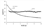
- FIG. 4 is a graph showing the relationship between the elapsed time from the start of evaluation (horizontal axis: time (h)), the temperature of the cooled object, and the outside air temperature (vertical axis: temperature (° C.)) in Example 1. . As shown in FIG. 4, it was confirmed that the temperature of the object to be cooled decreases (that is, the object to be cooled is cooled) as the elapsed time from the start of evaluation progresses.
- the radiation cooling performance was evaluated by determining the temperature difference shown in the following formula (that is, the temperature of the cooled object 101 with respect to the outside air temperature).
- a negative temperature difference (° C.) and a larger absolute value mean that the radiant cooling performance is superior.
- the results (temperature difference) are shown in Table 1.
- Temperature difference (° C) temperature of cooled object 101 (° C)-outside air temperature (° C)
- Example 2 In the production of the radiation cooling device 100, the same operation as in Example 1 was performed except that the internal far-infrared reflective film 14 was not used. The results are shown in Table 1.
- Example 3 The same operation as in Example 2 was performed except that the degree of vacuum P in the vacuum heat insulating container 10 at the time of evaluation was changed to the value shown in Table 1. The results are shown in Table 1.
- Example 4 The same operation as in Example 2 was performed except that the far-infrared radiator 30 was changed to a far-infrared radiator having spectroscopic measurements shown in Table 1.
- a multilayer film of SiO 2 film and TiO 2 film (in detail, by sputtering on the surface of an aluminum disk having a diameter of 140 mm, a thickness of 5 mm, and a heat capacity of 350 J / K) Used a far-infrared radiator formed with a multilayer film having a laminated structure of TiO 2 film / SiO 2 film / TiO 2 film.
- the laminated structure of the far-infrared radiator and the film thickness of each film in Example 4 are TiO 2 film (film thickness 1463 nm) / SiO 2 film (film thickness 643 nm) / TiO 2 film (film thickness 1428 nm) / Al substrate. .
- Example 5 The same operation as in Example 2 was performed except that the far-infrared transmitting window member 20 was changed to a far-infrared transmitting window member having spectroscopic measurements shown in Table 1. Specifically, as the far-infrared transmitting window member in Example 5, zinc sulfide particles having a number average particle diameter of 0.2 ⁇ m are dispersed on the surface of the far-infrared transmitting window member used in Example 2, thereby obtaining zinc sulfide. A far-infrared transmitting window member formed with a sunlight reflecting layer made of particles was used.
- Example 6 The same operation as in Example 2 was performed except that the far-infrared transmitting window member 20 was changed to a far-infrared transmitting window member having spectroscopic measurements shown in Table 1.
- a multilayer film specifically, a multilayer structure of ZnS film / Ge film / TiO 2 film / Ge film / ZnS film is formed on the surface of the Ge substrate by sputtering.
- An infrared transmission window member in which a multilayer film having a multilayer structure is formed was used.
- a germanium plate manufactured by IR System having the same shape as that of the far-infrared transmitting window member of Example 2 and having a diameter of 160 mm and a thickness of 5 mm was used.
- the laminated structure of this far infrared ray transmission window member and the film thickness of each film are as follows: ZnS film (film thickness 109 nm) / Ge film (film thickness 322 nm) / TiO 2 film (film thickness 600 nm) / Ge film (film thickness 43 nm) / ZnS film (film thickness 624 nm) / Ge substrate.
- Example 7 the radiant cooling device 150 shown in FIG. 3 was produced.
- the metal cylinder member 60 is provided on the opposite side of the far-infrared transmitting window member 20 as viewed from the far-infrared transmitting window member 20 as an international metal member 60.
- a parabolic mirror manufactured by Shoji Co., Ltd.
- the surface material is aluminum (aluminum coating)) was attached.
- the parabolic mirror was attached so that one end in the axial direction was in contact with the far-infrared transmitting window member 20 and the diameter increased in the direction from one end to the other end in the axial direction. Further, the parabolic mirror is configured such that the opening 10A is included in a range surrounded by the inner peripheral surface on one end side of the metal cylinder member 60 in a plan view (not shown) viewed from the opening direction of the opening 10A. Attached. The opening area of the other end side in the axial direction of the parabolic mirror (that is, the end portion far from the far-infrared transmitting window member 20) was 1.5 times the area of the opening portion 10A.
- Example 2 The same evaluation as in Example 2 was performed using the above-described radiation cooling device 150. The results are shown in Table 1.
- Example 1 In the evaluation of the radiation cooling performance, the same evaluation as in Example 2 was performed except that the vacuum pump was not operated and the inside of the vacuum heat insulating container 10 was set to atmospheric pressure. The results are shown in Table 1.
- Example 2 In the production of the radiant cooling device, the same operation as in Example 2 was performed except that the far-infrared radiator 30 was changed to an aluminum disk before the blackbody paint was applied. The results are shown in Table 1.
- the average emissivity E 8-13 of the aluminum disk was 0.05.
- the far-infrared radiator referred to in the present specification means a radiator having an average emissivity E 8-13 of 0.40 or more. Not applicable to the body.
Landscapes
- Engineering & Computer Science (AREA)
- General Engineering & Computer Science (AREA)
- Physics & Mathematics (AREA)
- Mechanical Engineering (AREA)
- Thermal Sciences (AREA)
- Health & Medical Sciences (AREA)
- Toxicology (AREA)
- Combustion & Propulsion (AREA)
- Chemical & Material Sciences (AREA)
- Thermal Insulation (AREA)
- Devices That Are Associated With Refrigeration Equipment (AREA)
- Packages (AREA)
- Cooling Or The Like Of Electrical Apparatus (AREA)
- Cooling Or The Like Of Semiconductors Or Solid State Devices (AREA)
Abstract
L'invention concerne un dispositif de refroidissement par rayonnement (100) comprenant: un récipient d'isolation sous vide (10) pour loger un objet à refroidir à l'intérieur de celui-ci et pour isoler sous vide l'objet à refroidir depuis l'extérieur, et qui est pourvu d'une ouverture (10A); un radiateur à infrarouge lointain (30) disposé entre l'objet à refroidir à l'intérieur du récipient d'isolation sous vide et l'ouverture, isolé sous vide depuis l'extérieur du récipient d'isolation sous vide, et qui effectue un contact thermique avec l'objet à refroidir et rayonne des rayons infrarouges lointains dans une plage de longueurs d'onde de 8 µm à 13 µm; et un élément de fenêtre de transmission infrarouge lointain (20) qui ferme l'ouverture du récipient d'isolation sous vide et permet aux rayons infrarouges lointains émis par le radiateur infrarouge lointain de passer à travers celui-ci.
Priority Applications (3)
| Application Number | Priority Date | Filing Date | Title |
|---|---|---|---|
| CN201780058622.1A CN109791016B (zh) | 2016-09-30 | 2017-09-22 | 辐射冷却装置及其在被冷却体的冷却中的应用 |
| JP2018542504A JP6602488B2 (ja) | 2016-09-30 | 2017-09-22 | 放射冷却装置 |
| US16/362,699 US20190257557A1 (en) | 2016-09-30 | 2019-03-25 | Radiative cooling device |
Applications Claiming Priority (2)
| Application Number | Priority Date | Filing Date | Title |
|---|---|---|---|
| JP2016194976 | 2016-09-30 | ||
| JP2016-194976 | 2016-09-30 |
Related Child Applications (1)
| Application Number | Title | Priority Date | Filing Date |
|---|---|---|---|
| US16/362,699 Continuation US20190257557A1 (en) | 2016-09-30 | 2019-03-25 | Radiative cooling device |
Publications (1)
| Publication Number | Publication Date |
|---|---|
| WO2018062012A1 true WO2018062012A1 (fr) | 2018-04-05 |
Family
ID=61760635
Family Applications (1)
| Application Number | Title | Priority Date | Filing Date |
|---|---|---|---|
| PCT/JP2017/034213 Ceased WO2018062012A1 (fr) | 2016-09-30 | 2017-09-22 | Dispositif de refroidissement par rayonnement |
Country Status (4)
| Country | Link |
|---|---|
| US (1) | US20190257557A1 (fr) |
| JP (1) | JP6602488B2 (fr) |
| CN (1) | CN109791016B (fr) |
| WO (1) | WO2018062012A1 (fr) |
Cited By (2)
| Publication number | Priority date | Publication date | Assignee | Title |
|---|---|---|---|---|
| CN110608548A (zh) * | 2019-10-21 | 2019-12-24 | 浙江耀伏能源管理有限公司 | 带空气流道的平板式地面太空辐射冷却器 |
| WO2020116111A1 (fr) * | 2018-12-04 | 2020-06-11 | 富士フイルム株式会社 | Structure multicouche |
Families Citing this family (5)
| Publication number | Priority date | Publication date | Assignee | Title |
|---|---|---|---|---|
| WO2018062011A1 (fr) * | 2016-09-30 | 2018-04-05 | 富士フイルム株式会社 | Dispositif de refroidissement par rayonnement |
| US12209826B2 (en) * | 2018-07-02 | 2025-01-28 | Massachusetts Institute Of Technology | Passive radiative cooling during the day |
| CN113513858B (zh) | 2020-04-09 | 2023-10-31 | 香港科技大学 | 具有增强的选择性红外发射的辐射制冷结构 |
| KR20220091269A (ko) * | 2020-12-23 | 2022-06-30 | 한국과학기술원 | 입사 및 방사 각도 제어 기반의 복사냉각 디바이스 |
| CN119911445B (zh) * | 2025-01-17 | 2025-10-24 | 中国科学院微小卫星创新研究院 | 一种用于航天器地面试验的超稳热环境模拟器 |
Citations (9)
| Publication number | Priority date | Publication date | Assignee | Title |
|---|---|---|---|---|
| JPS54139150A (en) * | 1978-04-20 | 1979-10-29 | Shin Meiwa Ind Co Ltd | Radiation cooling apparatus |
| JPS60243435A (ja) * | 1984-05-16 | 1985-12-03 | Takeo Saito | 冷房用長期蓄冷装置 |
| JPS6129664A (ja) * | 1984-07-20 | 1986-02-10 | 増淵 秀雄 | 無動力で低温を得る方法 |
| US20050167612A1 (en) * | 2004-02-02 | 2005-08-04 | Aubrey Jaffer | Passive fluorescent cooling |
| US20100155043A1 (en) * | 2007-06-19 | 2010-06-24 | University Of Technology | Element for emission of thermal radiation |
| JP2015169372A (ja) * | 2014-03-06 | 2015-09-28 | 大日本印刷株式会社 | 断熱容器および断熱容器の製造方法 |
| JP2016121328A (ja) * | 2014-09-22 | 2016-07-07 | 宰 山田 | 遠赤外線放射材料の用途およびその適用方法 |
| CN105972856A (zh) * | 2016-07-01 | 2016-09-28 | 中国科学技术大学 | 一种新型太阳能冰箱 |
| JP2016188715A (ja) * | 2015-03-30 | 2016-11-04 | イムラ・ジャパン株式会社 | 放射冷却装置および冷却光利用システム |
Family Cites Families (7)
| Publication number | Priority date | Publication date | Assignee | Title |
|---|---|---|---|---|
| FR82838E (fr) * | 1962-12-27 | 1964-04-24 | Centre Nat Rech Scient | Dispositif pour l'abaissement de la température d'un corps par son propre rayonnement et application à la production de froid |
| US4423605A (en) * | 1981-07-17 | 1984-01-03 | The United States Of America As Represented By The Administrator Of The National Aeronautics And Space Administration | Radiative cooler |
| DE19955277A1 (de) * | 1999-11-17 | 2001-05-23 | Suthoff Erika | Verfahren und Vorrichtung zur Beeinflussung des Wärmehaushaltes eines Körpers durch eine spezielle Wärmesenke |
| JP2006250513A (ja) * | 2005-03-14 | 2006-09-21 | Noritake Co Ltd | 遠赤外線放射冷却装置 |
| JP5489824B2 (ja) * | 2010-04-02 | 2014-05-14 | 富士フイルム株式会社 | 反射防止膜及び赤外線用光学素子 |
| CN102249009A (zh) * | 2011-05-12 | 2011-11-23 | 南京理工大学 | 用于航天器的热致变色可变发射率热控器件 |
| US10088251B2 (en) * | 2014-05-21 | 2018-10-02 | The Board Of Trustees Of The Leland Stanford Junior University | Radiative cooling with solar spectrum reflection |
-
2017
- 2017-09-22 WO PCT/JP2017/034213 patent/WO2018062012A1/fr not_active Ceased
- 2017-09-22 CN CN201780058622.1A patent/CN109791016B/zh active Active
- 2017-09-22 JP JP2018542504A patent/JP6602488B2/ja active Active
-
2019
- 2019-03-25 US US16/362,699 patent/US20190257557A1/en not_active Abandoned
Patent Citations (9)
| Publication number | Priority date | Publication date | Assignee | Title |
|---|---|---|---|---|
| JPS54139150A (en) * | 1978-04-20 | 1979-10-29 | Shin Meiwa Ind Co Ltd | Radiation cooling apparatus |
| JPS60243435A (ja) * | 1984-05-16 | 1985-12-03 | Takeo Saito | 冷房用長期蓄冷装置 |
| JPS6129664A (ja) * | 1984-07-20 | 1986-02-10 | 増淵 秀雄 | 無動力で低温を得る方法 |
| US20050167612A1 (en) * | 2004-02-02 | 2005-08-04 | Aubrey Jaffer | Passive fluorescent cooling |
| US20100155043A1 (en) * | 2007-06-19 | 2010-06-24 | University Of Technology | Element for emission of thermal radiation |
| JP2015169372A (ja) * | 2014-03-06 | 2015-09-28 | 大日本印刷株式会社 | 断熱容器および断熱容器の製造方法 |
| JP2016121328A (ja) * | 2014-09-22 | 2016-07-07 | 宰 山田 | 遠赤外線放射材料の用途およびその適用方法 |
| JP2016188715A (ja) * | 2015-03-30 | 2016-11-04 | イムラ・ジャパン株式会社 | 放射冷却装置および冷却光利用システム |
| CN105972856A (zh) * | 2016-07-01 | 2016-09-28 | 中国科学技术大学 | 一种新型太阳能冰箱 |
Cited By (5)
| Publication number | Priority date | Publication date | Assignee | Title |
|---|---|---|---|---|
| WO2020116111A1 (fr) * | 2018-12-04 | 2020-06-11 | 富士フイルム株式会社 | Structure multicouche |
| JPWO2020116111A1 (ja) * | 2018-12-04 | 2021-09-27 | 富士フイルム株式会社 | 多層構造体 |
| US11360249B2 (en) | 2018-12-04 | 2022-06-14 | Fujifilm Corporation | Multilayer structure |
| CN110608548A (zh) * | 2019-10-21 | 2019-12-24 | 浙江耀伏能源管理有限公司 | 带空气流道的平板式地面太空辐射冷却器 |
| CN110608548B (zh) * | 2019-10-21 | 2024-04-23 | 浙江耀伏能源管理有限公司 | 带空气流道的平板式地面太空辐射冷却器 |
Also Published As
| Publication number | Publication date |
|---|---|
| CN109791016B (zh) | 2020-12-29 |
| CN109791016A (zh) | 2019-05-21 |
| JPWO2018062012A1 (ja) | 2019-02-14 |
| JP6602488B2 (ja) | 2019-11-06 |
| US20190257557A1 (en) | 2019-08-22 |
Similar Documents
| Publication | Publication Date | Title |
|---|---|---|
| JP6602488B2 (ja) | 放射冷却装置 | |
| JP6602487B2 (ja) | 放射冷却装置 | |
| Lee et al. | Sub-ambient daytime radiative cooling by silica-coated porous anodic aluminum oxide | |
| Kim et al. | Visibly transparent radiative cooler under direct sunlight | |
| JP6584681B2 (ja) | 積層構造 | |
| Zhang et al. | A flexible film to block solar radiation for daytime radiative cooling | |
| JP7516253B2 (ja) | 受動放射冷却のための製作方法、構造体、および使用 | |
| Cui et al. | Progress of passive daytime radiative cooling technologies towards commercial applications | |
| CN110216924A (zh) | 一种复合辐射制冷膜 | |
| Goyal et al. | Recent advances and progresses in photonic devices for passive radiative cooling application: a review | |
| US10508838B2 (en) | Ultrahigh-performance radiative cooler | |
| US4624113A (en) | Passive-solar directional-radiating cooling system | |
| Son et al. | Temperature‐sensitive colored radiative cooling materials with efficient cooling performance | |
| JP2019066101A (ja) | 天空放射冷却装置 | |
| Dong et al. | A weather-resistant daytime radiative cooler based on fluorocarbon resin | |
| Wang et al. | Nano-engineered metafilms enable radiative cooling windows for energy-efficient buildings | |
| Pradhan et al. | Thin nanoporous anodic alumina film on aluminium for passive radiative cooling | |
| Pour et al. | A simple, cheap and effective glass coating for selective solar transmittance and radiative cooling applications | |
| KR102442291B1 (ko) | 홀 패턴층 기반의 복사 냉각 소자 | |
| JP6942270B2 (ja) | 多層構造体 | |
| Zhang et al. | Optimal design and preparation of high-performance multilayered thin film daytime radiative coolers | |
| Zhu et al. | Thin films of high reflectivity for efficient radiative cooling | |
| JP2025170795A (ja) | 金属層と分布ブラッグ反射器とを有し、紫外線、可視光及び近赤外線の波長帯域で光を反射する光反射器、及び光反射器を用いた放射冷却装置 | |
| US20240077653A1 (en) | Radiative Cooling Structure and Manufacturing Method | |
| DO HYEON et al. | Ultra-thin and near-unity selective emitter for efficient cooling |
Legal Events
| Date | Code | Title | Description |
|---|---|---|---|
| DPE2 | Request for preliminary examination filed before expiration of 19th month from priority date (pct application filed from 20040101) | ||
| ENP | Entry into the national phase |
Ref document number: 2018542504 Country of ref document: JP Kind code of ref document: A |
|
| 121 | Ep: the epo has been informed by wipo that ep was designated in this application |
Ref document number: 17855966 Country of ref document: EP Kind code of ref document: A1 |
|
| NENP | Non-entry into the national phase |
Ref country code: DE |
|
| 122 | Ep: pct application non-entry in european phase |
Ref document number: 17855966 Country of ref document: EP Kind code of ref document: A1 |