WO2020116111A1 - Structure multicouche - Google Patents
Structure multicouche Download PDFInfo
- Publication number
- WO2020116111A1 WO2020116111A1 PCT/JP2019/044510 JP2019044510W WO2020116111A1 WO 2020116111 A1 WO2020116111 A1 WO 2020116111A1 JP 2019044510 W JP2019044510 W JP 2019044510W WO 2020116111 A1 WO2020116111 A1 WO 2020116111A1
- Authority
- WO
- WIPO (PCT)
- Prior art keywords
- base material
- material layer
- multilayer structure
- layer
- structure according
- Prior art date
- Legal status (The legal status is an assumption and is not a legal conclusion. Google has not performed a legal analysis and makes no representation as to the accuracy of the status listed.)
- Ceased
Links
Images

Classifications
-
- G—PHYSICS
- G02—OPTICS
- G02B—OPTICAL ELEMENTS, SYSTEMS OR APPARATUS
- G02B5/00—Optical elements other than lenses
- G02B5/20—Filters
- G02B5/208—Filters for use with infrared or ultraviolet radiation, e.g. for separating visible light from infrared and/or ultraviolet radiation
-
- B—PERFORMING OPERATIONS; TRANSPORTING
- B32—LAYERED PRODUCTS
- B32B—LAYERED PRODUCTS, i.e. PRODUCTS BUILT-UP OF STRATA OF FLAT OR NON-FLAT, e.g. CELLULAR OR HONEYCOMB, FORM
- B32B3/00—Layered products comprising a layer with external or internal discontinuities or unevennesses, or a layer of non-planar shape; Layered products comprising a layer having particular features of form
- B32B3/26—Layered products comprising a layer with external or internal discontinuities or unevennesses, or a layer of non-planar shape; Layered products comprising a layer having particular features of form characterised by a particular shape of the outline of the cross-section of a continuous layer; characterised by a layer with cavities or internal voids ; characterised by an apertured layer
-
- B—PERFORMING OPERATIONS; TRANSPORTING
- B32—LAYERED PRODUCTS
- B32B—LAYERED PRODUCTS, i.e. PRODUCTS BUILT-UP OF STRATA OF FLAT OR NON-FLAT, e.g. CELLULAR OR HONEYCOMB, FORM
- B32B7/00—Layered products characterised by the relation between layers; Layered products characterised by the relative orientation of features between layers, or by the relative values of a measurable parameter between layers, i.e. products comprising layers having different physical, chemical or physicochemical properties; Layered products characterised by the interconnection of layers
- B32B7/02—Physical, chemical or physicochemical properties
- B32B7/023—Optical properties
-
- F—MECHANICAL ENGINEERING; LIGHTING; HEATING; WEAPONS; BLASTING
- F25—REFRIGERATION OR COOLING; COMBINED HEATING AND REFRIGERATION SYSTEMS; HEAT PUMP SYSTEMS; MANUFACTURE OR STORAGE OF ICE; LIQUEFACTION SOLIDIFICATION OF GASES
- F25B—REFRIGERATION MACHINES, PLANTS OR SYSTEMS; COMBINED HEATING AND REFRIGERATION SYSTEMS; HEAT PUMP SYSTEMS
- F25B23/00—Machines, plants or systems, with a single mode of operation not covered by groups F25B1/00 - F25B21/00, e.g. using selective radiation effect
- F25B23/003—Machines, plants or systems, with a single mode of operation not covered by groups F25B1/00 - F25B21/00, e.g. using selective radiation effect using selective radiation effect
-
- G—PHYSICS
- G02—OPTICS
- G02B—OPTICAL ELEMENTS, SYSTEMS OR APPARATUS
- G02B1/00—Optical elements characterised by the material of which they are made; Optical coatings for optical elements
- G02B1/04—Optical elements characterised by the material of which they are made; Optical coatings for optical elements made of organic materials, e.g. plastics
-
- B—PERFORMING OPERATIONS; TRANSPORTING
- B32—LAYERED PRODUCTS
- B32B—LAYERED PRODUCTS, i.e. PRODUCTS BUILT-UP OF STRATA OF FLAT OR NON-FLAT, e.g. CELLULAR OR HONEYCOMB, FORM
- B32B7/00—Layered products characterised by the relation between layers; Layered products characterised by the relative orientation of features between layers, or by the relative values of a measurable parameter between layers, i.e. products comprising layers having different physical, chemical or physicochemical properties; Layered products characterised by the interconnection of layers
- B32B7/02—Physical, chemical or physicochemical properties
- B32B7/027—Thermal properties
-
- G—PHYSICS
- G02—OPTICS
- G02B—OPTICAL ELEMENTS, SYSTEMS OR APPARATUS
- G02B5/00—Optical elements other than lenses
- G02B5/20—Filters
- G02B5/26—Reflecting filters
Definitions
- the present disclosure relates to a multilayer structure.
- U.S. Patent Application Publication No. 2015/0338175 is a radiant cooling device for cooling an object, wherein a plurality of different materials located at different depths along the depth dimension with respect to the object. And a plurality of different materials including a solar spectrum reflecting portion and a heat radiating portion.
- a plurality of transparent plates having a high long-wavelength transmittance, which face each other with a predetermined space therebetween, are provided above the heat sink so as to face the heat sink. Further, there is disclosed a radiant cooler characterized by being provided with a predetermined interval.
- JP-A-2008-114583 a multilayer structure having a structure in which three or more light-transmitting base films are opposed to each other with a plurality of resin spacers made of a resin composition for spacers sandwiched therebetween.
- the resin spacers are arranged so as to overlap each other in the laminating direction of the base films with the base film sandwiched therebetween.
- An object of one embodiment of the present disclosure is to provide a multilayer structure having an excellent radiative cooling effect and capable of cooling an object to be cooled arranged inside the structure.
- Means for solving the above problems include the following aspects. ⁇ 1> A radiator, a base material layer including a region that forms an interface in the internal structure, and a first air layer provided between the radiator and the base material layer, and The far infrared ray transmittance B of the base material layer and the sunlight reflectance A of the multilayer structure satisfy B/(100-A)>7, and the sunlight reflectance C of the base material layer is 30% or more. Multi-layer structure. ⁇ 2> The multilayer structure according to ⁇ 1>, in which the far infrared ray transmittance B of the base material layer and the sunlight reflectance C of the base material layer satisfy B/(100-C)>7.
- ⁇ 3> The multilayer structure according to ⁇ 1> or ⁇ 2>, wherein the number of the base material layers is two or more.
- ⁇ 4> The multilayer structure according to ⁇ 3>, which has a second air layer between the base material layers.
- ⁇ 5> The multilayer structure according to ⁇ 4>, which has a structure in which the base material layer and the second air layer are alternately arranged.
- ⁇ 6> The multilayer structure according to ⁇ 4> or ⁇ 5>, wherein the second air layer has a thickness of 5 cm or less.
- ⁇ 7> The far-infrared ray transmittance B of the base material layer and the sunlight reflectance A of the multilayer structure satisfy B/(100-A)>20.
- ⁇ 1> to ⁇ 6> Multi-layered structure.
- ⁇ 8> The multilayer structure according to any one of ⁇ 1> to ⁇ 7>, in which the sunlight reflectance C of the base material layer is 80% or more.
- ⁇ 9> The multilayer structure according to any one of ⁇ 1> to ⁇ 8>, wherein an average diameter of a region forming an interface in the internal structure is 5000 nm or less.
- ⁇ 10> The multilayer structure according to any one of ⁇ 1> to ⁇ 9>, in which a region forming an interface in the internal structure is at least one selected from voids and particles.
- ⁇ 11> The multilayer structure according to any one of ⁇ 1> to ⁇ 10>, wherein the base material layer is a porous base material layer.
- ⁇ 12> The multilayer structure according to any one of ⁇ 1> to ⁇ 11>, wherein the base material layer has a porosity of 40% or more.
- ⁇ 13> The multilayer structure according to any one of ⁇ 1> to ⁇ 12>, in which the base material layer contains a polyolefin.
- ⁇ 14> The multilayer structure according to any one of ⁇ 1> to ⁇ 13>, which is a radiation cooling structure.
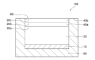
- FIG. 1 is a schematic cross-sectional view showing an example of the multilayer structure according to the present disclosure.
- FIG. 2 is a schematic cross-sectional view showing a modified example of the multilayer structure according to the present disclosure.
- a numerical range represented by “to” means a range including the numerical values before and after “to” as a lower limit value and an upper limit value.
- the upper limit value or the lower limit value described in a certain numerical range may be replaced with the upper limit value or the lower limit value of another stepwise described numerical range.
- the upper limit value or the lower limit value described in a certain numerical range may be replaced with the values shown in the examples.
- the amount of each component in the composition means the total amount of the plurality of substances present in the composition, unless there is a plurality of substances corresponding to each component in the composition, unless otherwise specified. ..
- “mass %” and “weight %” have the same meaning
- “mass part” and “weight part” have the same meaning.
- a combination of two or more preferable aspects is a more preferable aspect.
- a multilayer structure according to the present disclosure includes a radiator, a base layer including a region that forms an interface in an internal structure (hereinafter, may be simply referred to as “base layer”), the radiator, and the base.
- a first air layer provided between the base material layer and the material layer, and the far infrared transmittance B of the base material layer and the solar reflectance A of the multilayer structure are B/(100-A)> 7 is satisfied, and the sunlight reflectance C of the base material layer is 30% or more.
- a multilayer structure according to the present disclosure has an excellent radiative cooling effect, and can cool an object to be cooled arranged inside the structure. Although the reason why the multilayer structure according to the present disclosure exerts the above effect is not clear, it is presumed as follows.
- a multilayer structure according to the present disclosure includes a radiator, a base layer including a region forming an interface in an internal structure, and a first air layer provided between the radiator and the base layer.
- the temperature rise inside the multilayer structure can be reduced by reducing the amount of sunlight entering the multilayer structure due to the reflection of sunlight, and the radiation from the radiator is performed.
- Infrared rays can be easily emitted from the inside of the multilayer structure to the outside of the multilayer structure. Therefore, it is considered that the multilayer structure according to the present disclosure has an excellent radiative cooling effect and can cool the cooled object arranged inside the structure.
- the “inside the structure” in the “object to be cooled arranged inside the structure” means the whole or a part of the region between the radiator and the base material layer.
- cooling the cooled body means lowering the temperature of the cooled body than the temperature outside the multilayer structure, and not necessarily lowering the temperature of the cooled body to a specific temperature.
- the present invention is not limited to this, and includes maintaining the temperature of the cooled object not to exceed the outside air temperature.
- Far-infrared transmittance B of the base material layer and sunlight reflectance A of the multilayer structure more preferably satisfy B/(100-A)>7, and more preferably B/(100-A)>10. /(100-A)>15 is more preferable, B/(100-A)>20 is particularly preferable, and B/(100-A)>25 is most preferable.
- the upper limit value of B/(100-A) is not limited and can be set as appropriate according to the intended use.
- B/(100-A) the value of B (far infrared ray transmittance B of the base material layer) and the value of A (sunlight reflectance A of the multilayer structure) are each expressed as a percentage (%). To be done.
- the relational expression represented by B/(100-A)>7 is such that the sunlight reflectance A of the multilayer structure is large (in other words, the sunlight absorptivity is small) and the far-infrared ray transmission of the base material layer is It means that the rate B is large.
- the condition under which the radiator is cooled by radiation cooling is represented by P in ⁇ P out ⁇ 0 (hereinafter, referred to as “formula (A)”).
- P in represents the solar energy per unit area incident from the outside of the multilayer structure into the inside of the multilayer structure, and is represented by (100 ⁇ A) ⁇ P solar /100.
- A represents the sunlight reflectance (%) of the multilayer structure
- P solar represents the sunlight intensity.
- P out represents the energy radiated from the multilayer structure as far infrared rays per unit area, and is represented by (1- ⁇ sky ) ⁇ B ⁇ T amb 4 /100.
- ⁇ sky represents the effective emissivity of the sky
- B represents the far-infrared transmittance (%) of the base material layer
- ⁇ represents the Stefan-Boltzmann constant
- T amb represents the outside air temperature. .. It is known that ⁇ sky is about 0.7 in fine weather.
- B/(100 ⁇ A)>7 is derived from the equation (A). Therefore, the multilayer structure satisfying B/(100-A)>7 reflects sunlight and has a high far-infrared transmittance, so that it has an excellent radiative cooling effect, and a cooled object placed inside the structure. Can be cooled.
- the solar reflectance A of the multilayer structure can be measured by the following method.
- a method based on the method described in JIS A 5759:2008 using an integrating sphere spectrophotometer (for example, V-670, manufactured by JASCO Corporation), the radiator and the base material layer at wavelengths of 300 nm to 2500 nm Each diffuse reflectance is measured.
- the multilayer structure includes two or more base material layers, the diffuse reflectance is measured for each base material layer.
- the value calculated from the measured value based on the Fresnel multiple reflection theory is defined as the sunlight reflectance A.
- the diffuse reflectance of the other base material layer is also included in the calculation of the solar reflectance A.
- the far infrared ray transmittance B of the base material layer can be measured by the following method. Using a Fourier transform infrared spectrophotometer (eg VIR-100, JASCO Corporation) and an integrating sphere unit, the spectral infrared diffuse reflectance and the spectral infrared diffuse transmittance of the base material layer at a wavelength of 2 ⁇ m to 25 ⁇ m can be measured. taking measurement. When the multilayer structure includes two or more substrate layers, the spectral infrared diffuse transmittance is measured for each substrate layer, and the spectral infrared diffuse transmittance of the substrate layer is calculated based on the Fresnel multiple reflection theory. To calculate.
- a Fourier transform infrared spectrophotometer eg VIR-100, JASCO Corporation
- the value obtained by weighting the black spectral radiation intensity at 25° C. with respect to the obtained spectral infrared diffuse transmittance is defined as the far infrared transmittance B of the base material layer.
- the value obtained by multiplying the infrared diffuse transmittance T by the spectral black body radiation intensity I at a wavelength of 2 ⁇ m to 25 ⁇ m is calculated as “the spectral black body radiation intensity I
- the far-infrared transmittance B of the base material layer can be calculated by dividing by the “value integrated at 2 ⁇ m to 25 ⁇ m”.
- the spectral infrared diffuse transmittance of the other base material layer is also included in the calculation of the far infrared transmittance B.
- T represents the spectral infrared diffuse transmittance (%)
- I represents the spectral black body radiation intensity (W/m 2 ) at 25° C.
- ⁇ represents the wavelength ( ⁇ m).
- FIG. 1 schematically shows an example of a multilayer structure according to the present disclosure.
- the multilayer structure 100 is a radiant cooling structure, and includes a radiator 10, a base material layer 20a, a base material layer 20b, a base material layer 20c, and a first air layer. 30, a second air layer 40a, a second air layer 40b, and a housing 50 having an opening 60.
- the base material layer 20a, the base material layer 20b, and the base material layer 20c are provided in the opening 60 of the housing 50, respectively.
- the first air layer 30 is provided between the radiator 10 and the base material layer 20a.
- the second air layer 40a is provided between the base material layer 20a and the base material layer 20b.
- the second air layer 40b is provided between the base material layer 20b and the base material layer 20c.
- Infrared rays emitted from the radiator 10 pass through the first air layer 30, the base material layer 20a, the second air layer 40a, the base material layer 20b, the second air layer 40b, and the base material layer 20c, It is discharged to the outside of the multilayer structure 100.
- Each of the base material layer 20a, the base material layer 20b, and the base material layer 20c can reduce the temperature rise of the radiator 10 and the like by reducing the amount of sunlight entering the inside of the multilayer structure 100. ..
- the cooled object can be cooled by disposing the cooled object in the region of the first air layer 30 (for example, the surface of the radiator 10). ..
- the multilayer structure according to the present disclosure has a radiator. Since the multilayer structure has a radiator, infrared rays can be emitted and radiative cooling can be exhibited.
- radiator means an object that exhibits a high emissivity in a wavelength range where black body radiation occurs at room temperature (for example, 25° C.).
- the average emissivity of the radiator in the wavelength range of 25° C. and the wavelength of 5 ⁇ m to 25 ⁇ m is preferably 0.8 or more
- the average emissivity of the radiator in the wavelength range of 25° C. and the wavelength of 8 ⁇ m to 13 ⁇ m is It is more preferably 0.8 or more.
- the average emissivity of the radiator in the wavelength range of 5 ⁇ m to 25 ⁇ m can be measured by the following method.
- a Fourier transform infrared spectrophotometer eg, FTS-7000, manufactured by Varian
- FTS-7000 Fourier transform infrared spectrophotometer
- the arithmetic average value of the spectral emissivity at each wavelength is calculated, and the obtained value is set as the average emissivity in the wavelength range of 5 ⁇ m to 25 ⁇ m.
- the average emissivity of the radiator in the wavelength range of 8 ⁇ m to 13 ⁇ m is calculated by selecting the wavelength range of 8 ⁇ m to 13 ⁇ m in the above method instead of the wavelength range of 5 ⁇ m to 25 ⁇ m.
- the radiator is not limited as long as it has a high emissivity.
- Examples of the form of the radiator include a film, a sheet, a coating film, a heat insulating material, and a white reflector.
- the radiator may be a liquid such as water.
- the radiator may be arranged on a support (for example, a glass substrate, a resin film, a resin sheet).
- radiator examples include polyethylene terephthalate, glass, acrylic, urethane, silicone, water and the like.
- the radiator preferably exhibits diffuse reflection or specular reflection with respect to the spectrum of sunlight.
- a foamed resin is preferable, and a foamed polyethylene terephthalate is more preferable.
- radiators may be used as the radiator.
- Specific examples of commercially available products include MCPET (registered trademark, foamed polyethylene terephthalate white reflector, manufactured by Furukawa Electric Co., Ltd.), Lumirror (registered trademark) E20 (polyethylene terephthalate white reflective film, manufactured by Toray Industries, Inc.). Etc.
- the shape of the radiator is not limited and can be appropriately selected according to the application.
- Examples of the shape of the radiator include a planar shape, a curved shape, a spherical shape, a prism shape, and a box shape.
- the shape of the radiator surface is not limited.
- the surface of the radiator may be smooth or may have an uneven structure.
- the size of the radiator is not limited and can be set as appropriate according to the application.
- the thickness of the radiator can be 0.00001 cm to 50 cm.
- the radiator preferably exhibits a high reflectance with respect to sunlight from the viewpoint of reflecting sunlight that has passed through the base material layer.
- the solar reflectance of the radiator is preferably 70% or more, more preferably 80% or more, and particularly preferably 90% or more.
- the solar reflectance of the radiator can be measured by the following method.
- the diffuse reflectance of the radiator at a wavelength of 300 nm to 2500 nm was measured using an integrating sphere spectrophotometer (for example, V-670, manufactured by JASCO Corporation) by a method based on the method described in JIS A 5759:2008.
- the value obtained by measurement is taken as the sunlight reflectance.
- the multilayer structure according to the present disclosure has a base material layer including a region that forms an interface in the internal structure. Further, in the multilayer structure according to the present disclosure, the sunlight reflectance C of the base material layer is 30% or more. By having the base material layer including the region forming the interface in the internal structure and having the sunlight reflectance C of 30% or more, it is possible to enhance the reflectance of sunlight and enhance the radiation cooling effect.
- a region that forms an interface in the internal structure means a region that forms an interface with a main material (that is, a base material (matrix)) that constitutes the base material layer inside the base material layer, and is a tangible material. And intangible.
- the region forming the interface in the internal structure means a “void” that forms a solid-gas interface with the fibers of the nonwoven fabric.
- the region forming the interface in the internal structure means “particles” forming a solid-solid interface with the resin.
- the region forming the interface in the internal structure can be confirmed by observing the cross section of the base material layer using a scanning electron microscope (SEM).
- SEM scanning electron microscope
- the interface formed in the internal structure may be a solid-gas interface, a solid-liquid interface, a solid-solid interface, or a solid in view of sunlight reflectance. It is preferably at least one kind of interface selected from the group consisting of a gas interface and a solid-solid interface, and more preferably a solid-gas interface.
- the region forming the interface in the internal structure includes, for example, voids, bubbles, particles (for example, organic resin particles, inorganic particles) and the like.
- voids for example, a solid-gas interface is formed in the internal structure of the base material layer.
- a solid-solid interface is formed in the internal structure of the base material layer.
- the region forming the interface in the internal structure is preferably at least one selected from voids and particles, and more preferably voids, from the viewpoint of sunlight reflectance.
- the organic resin particles are not limited, and known organic resin particles can be applied. From the viewpoint of the reflectance of sunlight, the organic resin particles are preferably organic resin particles having a refractive index different from that of the material of the base material layer. Specific examples of the organic resin particles include acrylic resin particles, polyester particles, polyurethane particles, polycarbonate particles, polyolefin particles, polystyrene particles and the like.
- the inorganic particles are not limited, and known inorganic particles can be applied. From the viewpoint of sunlight reflectance, the inorganic particles are preferably inorganic particles having a refractive index different from that of the material of the base material layer. Specific examples of the inorganic particles include silicon oxide (silica) particles, titanium oxide (titania) particles, zirconium oxide (zirconia) particles, magnesium oxide (magnesia) particles, aluminum oxide (alumina) particles and the like.
- the shape of the area that forms the interface in the internal structure is not limited.
- the shape of the region forming the interface in the internal structure, which is observed in the cross section of the base material layer, may be, for example, a circular shape, an elliptical shape, or an irregular shape.
- the average diameter of the region forming the interface in the internal structure is preferably 5000 nm or less, more preferably 2000 nm or less, and more preferably 1000 nm or less from the viewpoint of sunlight reflectance and infrared transmittance. More preferably, it is particularly preferably 550 nm or less.
- the average diameter of the region forming the interface in the internal structure is preferably 30 nm or more, more preferably 50 nm or more, and particularly preferably 100 nm or more, from the viewpoint of sunlight reflectance.
- the average diameter of the region forming the interface in the internal structure can be measured by the following method. Ten cross-sections in the thickness direction of the base material layer are observed with a scanning electron microscope (for example, S4100, manufactured by Hitachi High-Technology Co., Ltd.) at a magnification of 1000 times, and a total of 10 observation images are acquired. From each image, 10 areas each forming an interface in the internal structure are selected (however, the number of areas forming an interface in the internal structure (hereinafter, sometimes referred to as “specific area” in this paragraph) is 10). For images that are less than, select a number of specific regions that corresponds to the maximum number of specific regions observed.
- a scanning electron microscope for example, S4100, manufactured by Hitachi High-Technology Co., Ltd.
- the material for the base layer is preferably a resin having a high infrared transmittance.
- the resin having a high infrared ray transmissivity include a resin having an infrared ray transmissivity of 50% or more in any wavelength range of 8 ⁇ m to 13 ⁇ m.
- Specific examples of the resin having a high infrared ray transmittance include chain polyolefins (for example, polyethylene and polypropylene), cyclic polyolefins (for example, polynorbornene), and polystyrene.
- the base material layer preferably contains polyolefin, and more preferably polyethylene, from the viewpoint of infrared ray transmittance.
- the content of the polyolefin in the base material layer is preferably 80% by mass to 100% by mass, and 90% by mass to 100% by mass with respect to the mass of the base material layer from the viewpoint of the infrared transmittance. It is more preferable that the content is 95% by mass to 100% by mass.
- the base material layer is preferably a base material layer containing particles or a porous base material layer, and more preferably a porous base material layer, from the viewpoint of sunlight reflection and infrared transmittance.
- the porous base material layer include a porous resin film and a nonwoven fabric.
- the base material layer is preferably a porous resin film or a non-woven fabric, more preferably a porous polyethylene film or a polyethylene non-woven fabric, and more preferably a polyethylene non-woven fabric, from the viewpoint of sunlight reflection and infrared transmittance. Particularly preferred.
- a commercially available product may be used as the base material layer.
- Examples of commercially available products include Tyvek (registered trademark, manufactured by Asahi DuPont Flash Span Products Co., Ltd.), Sunmap (registered trademark, manufactured by Nitto Denko Corporation), Mirim (registered trademark, Teijin Limited), and the like.
- the sunlight reflectance C of the base material layer is 30% or more, preferably 40% or more, more preferably 50% or more, further preferably 80% or more, and 90% or more. It is particularly preferable that By adjusting the sunlight reflectance C of the base material layer within the above numerical range, the radiation cooling effect is excellent, and the cooled object arranged inside the structure can be cooled.
- the upper limit of the sunlight reflectance C of the base material layer is not limited.
- the sunlight reflectance C of the base material layer can be 100% or less, for example.
- the sunlight reflectance C of the base material layer can be measured by the following method. According to the method described in JIS A 5759:2008, the diffuse reflectance of the base material layer at a wavelength of 300 nm to 2500 nm is measured using an integrating sphere spectrophotometer (for example, V-670, manufactured by JASCO Corporation). Then, the obtained value is defined as the sunlight reflectance C.
- the multilayer structure includes two or more base layers, the diffuse reflectance is measured for each base layer, and the solar reflectance C of the base layer is calculated based on the Fresnel multiple reflection theory. To do. Further, when the multilayer structure includes another base material layer described later, the diffuse reflectance of the other base material layer is also included in the calculation of the solar reflectance C.
- the far infrared ray transmittance B of the base material layer and the solar light reflectance C of the base material layer preferably satisfy B/(100-C)>7, and more preferably B/(100-C)>8. It is particularly preferable to satisfy B/(100-C)>10.
- the far-infrared transmittance B of the base material layer and the sunlight reflectance C of the base material layer satisfy the above relationship, the radiant cooling effect is excellent, and the cooled object arranged inside the structure can be cooled. ..
- the method of measuring the far infrared ray transmittance B of the base material layer and the sunlight reflectance C of the base material layer is as described above.
- the upper limit of B/(100-C) is not limited and can be set appropriately according to the intended use.
- B/(100-C) the value of B (far infrared ray transmittance B of the base material layer) and the value of C (sunlight reflectance C of the base material layer) are each expressed as a percentage (%). To be done.
- the relational expression represented by B/(100-C)>7 is a base material layer in place of the solar reflectance A of the multilayer structure in the relational expression represented by B/(100-A)>7.
- the solar light reflectance C of is considered. That is, the relational expression represented by B/(100-C)>7 means that the sunlight reflectance C of the base material layer is large and the far infrared ray transmittance B of the base material layer is large.
- the porosity of the base material layer is preferably 40% or more, more preferably 45% or more, further preferably 50% or more, and more preferably 60% or more, from the viewpoint of infrared ray transmittance. Is particularly preferable. From the viewpoint of the strength of the base material, the porosity of the base material layer is preferably 90% or less, and more preferably 80% or less.
- the porosity of the base material layer can be measured by the following method.
- the volume and mass of the base material layer are measured to calculate the density of the base material layer.
- the ratio of the density of the base material layer to the density of the material forming the base material layer is calculated, and the obtained value is defined as the porosity of the base material layer.
- the arithmetic mean value of the ratio of the density of the base layer to the density of the material forming the base layer is calculated, and the obtained value is the porosity of the base layer.
- the volume of the base material layer is measured by the Archimedes method (solvent: water, temperature: 25°C), and the mass of the base material layer is measured using a balance.
- the method of measuring the density of the material forming the base material layer the method of measuring the density of the base material layer can be applied, if necessary.
- the number of base material layers is at least one, preferably two or more, and more preferably three or more. By setting the number of base material layers to two or more, the reflectance of sunlight can be improved and a high heat insulating effect can also be obtained.
- the number of base material layers is preferably 7 or less, and more preferably 5 or less, from the viewpoint of infrared transmittance. When there are two or more base material layers, the base material layers may be the same or different from each other.
- the distance between the base material layers is preferably 5 cm or less, more preferably 4 cm or less, and particularly preferably 3 cm or less.
- the lower limit of the distance between the base material layers is not limited.
- the distance between the base material layers can be, for example, 0.1 cm or more.
- the distance between the base material layers can be measured by the following method. The minimum value and the maximum value of the distance between the two base material layers facing each other are measured, and the arithmetic mean value of the measured values is taken as the distance between the base material layers. When the distance between the base material layers is two or more, the distance between the base material layers is obtained by the same method as described above, and the arithmetic mean value of the obtained values is used as the distance between the base material layers.
- the base layer is preferably arranged on the radiator from the viewpoint of radiation cooling.
- the base material layer may be arranged at a position where the horizontal surface and the main surface of the base material layer are parallel to each other, or may be arranged at a position where the horizontal surface and the main surface of the base material layer intersect. From the viewpoint of radiation cooling and sunlight reflectance, the base material layer is preferably arranged at a position where the incident direction of sunlight and the main surface of the base material layer intersect.
- the relative positional relationship of each base material layer is not limited.
- each base material layer may be arranged hierarchically or may not be arranged hierarchically (for example, each base material layer is on the same plane).
- the base material layers are arranged hierarchically from the viewpoint of radiative cooling and solar reflectance, and the incident direction of sunlight and each base material. It is more preferable that the layers are arranged hierarchically at a position where the main surfaces of the layers intersect.
- the “main surface of the base material layer” means the surface of the base material layer orthogonal to the thickness direction of the base material layer.
- the thickness of the base material layer is not limited and can be set appropriately according to the application.
- the thickness of the base material layer may be, for example, 20 ⁇ m to 5000 ⁇ m.
- the base material layer may be provided on an inner peripheral portion, an opening portion, or the like of the housing described later, or may be provided via a spacer.
- the multilayer structure according to the present disclosure has a first air layer provided between the radiator and the base material layer. Since the multilayer structure has the first air layer, a high heat insulating effect can be obtained.
- the medium forming the first air layer is not necessarily limited to air, but may be a gas such as nitrogen or argon. From the viewpoint of workability, the medium forming the first air layer is preferably air.
- the first air layer may be provided between the radiator and the base layer, and the radiator and the base layer facing each other (in the case where the multilayer structure has two or more base layers, It is preferable that the space is formed by a base material layer provided on the side closest to the radiator of the two or more base material layers). Further, the first air layer may be a space formed by the radiator and the other base material layer facing each other without departing from the gist of the present disclosure, and two other base materials facing each other. It may be a space formed by layers. The other base material layers will be described later.
- the size and capacity of the first air layer are not limited and can be appropriately set according to the application.
- the multilayer structure according to the present disclosure has two or more base material layers
- the number of the second air layers may be one, or two or more.
- the second air layer has only to be provided between the base material layers, and from the viewpoint of heat insulation, it is preferably a space formed by two base material layers facing each other.
- the multilayer structure according to the present disclosure preferably has a structure in which the base material layers and the second air layers are alternately arranged from the viewpoint of heat insulation.
- the thickness of the second air layer is preferably 5 cm or less, more preferably 4 cm or less, and particularly preferably 3 cm or less. By adjusting the thickness of the second air layer within the above numerical range, convection in the air layer can be suppressed and the heat insulating effect can be further improved.
- the lower limit of the thickness of the second air layer is not limited.
- the thickness of the second air layer can be, for example, 0.1 cm or more.
- the thickness of the second air layer can be measured by the following method.
- the minimum value and the maximum value of the thickness of the second air layer are measured, and the arithmetic mean value of the measured values is set as the thickness of the second air layer.
- the thickness of the second air layer is obtained by the same method as described above, and the arithmetic mean value of the obtained values is set as the thickness of the second air layer. ..
- the multilayer structure according to the present disclosure includes a region that forms an interface in the internal structure in a range that satisfies B/(100-A)>7 and a range that the solar reflectance C of the base material layer is 30% or more. It may have a base material layer (hereinafter, may be referred to as “other base material layer”). Examples of the other base material layer include resin films such as polyolefin films. The number of other base material layers may be one, or two or more.
- the ratio of the number of base material layers including a region forming an interface in the internal structure is defined as a base material layer including a region forming an interface in the internal structure and a base material layer not including a region forming an interface in the internal structure (that is, It is preferably 50% or more, more preferably 65% or more, further preferably 80% or more, particularly preferably 90% or more, based on the total number of other base material layers). , 100% is most preferable.
- the multilayer structure according to the present disclosure may have a housing.
- a housing for example, a radiator, a base material layer, a first air layer, and the like can be provided inside the housing.
- the case may be composed of a single member, or may be composed of a combination of a plurality of members.
- the housing is preferably made of a heat insulating material from the viewpoint of heat insulating properties.
- the heat insulating material is not limited and can be appropriately selected from known heat insulating materials.
- the housing has an opening at least in the upper part.
- the number of openings is not limited and may be one or may be two or more, and is preferably one from the viewpoint of radiative cooling.
- the shape of the opening is not limited and can be appropriately selected according to the application. Examples of the shape of the opening include a circle, a quadrangle, a hexagon, and an irregular shape.
- FIG. 2 schematically shows a modified example of the multilayer structure according to the present disclosure.
- the multilayer structure 101 is a radiation cooling structure, and has a radiator 11 having an opening 61, a base material layer 21a, a base material layer 21b, and a base material layer 21c. It has a first air layer 31, a second air layer 41a, and a second air layer 41b.
- the base material layer 21a, the base material layer 21b, and the base material layer 21c are provided in the opening 61 of the radiator 11, respectively.
- the first air layer 31 is provided between the radiator 11 and the base material layer 21a.
- the second air layer 41a is provided between the base material layer 21a and the base material layer 21b.
- the second air layer 41b is provided between the base material layer 21b and the base material layer 21c.
- the multilayer structure according to the present disclosure has an excellent radiative cooling effect and can cool an object to be cooled arranged inside the structure, and thus is preferably used as a radiative cooling structure (for example, a radiative cooling device).
- a radiative cooling structure for example, a radiative cooling device.
- the multilayer structure according to the present disclosure can be applied to, for example, a window material, a roof heat shield, a cooler, or the like. Note that the use of the multilayer structure according to the present disclosure is not limited to cooling the cooled object arranged inside the structure.
- the multilayer structure according to the present disclosure can be applied to various cooling techniques utilizing radiative cooling, as exemplified above.
- Example 1 Using a heat insulating material (product name: Styloace-II, manufactured by Dow Kako Co., Ltd.) having a thickness of 10 cm, a housing having one opening at the top was manufactured. The dimensions inside the housing are 30 cm in length, 40 cm in width, and 10 cm in height. As a radiator, a white reflector (foamed polyethylene terephthalate, product name: MCPET, manufactured by Furukawa Electric Co., Ltd.) was provided on the bottom surface inside the housing.
- a white reflector fuoamed polyethylene terephthalate, product name: MCPET, manufactured by Furukawa Electric Co., Ltd.
- one polyethylene non-woven fabric product name: Tyvek 1442R, void ratio: 69%, average diameter of voids: 500 nm, thickness: S: 140 ⁇ m, Asahi DuPont Flash Span Products Co., Ltd. were provided to obtain a multilayer structure (hereinafter, may be simply referred to as “structure”).
- structure An air layer formed of a white reflector and a polyethylene non-woven fabric exists inside the housing.
- Example 2 A multilayer structure was obtained in the same manner as in Example 1 except that two polyethylene nonwoven fabrics used in Example 1 were provided at intervals of 4 cm. In addition, the distance between the polyethylene nonwoven fabric closest to the white reflector and the white reflector is 2 cm.
- Example 3 A multilayer structure was obtained in the same manner as in Example 1 except that three polyethylene nonwoven fabrics used in Example 1 were provided at 3 cm intervals. In addition, the distance between the polyethylene nonwoven fabric closest to the white reflector and the white reflector is 2 cm.
- Example 4 Instead of the polyethylene nonwoven fabric used in Example 1, a porous polyethylene film (product name: Sunmap LC0.2t, porosity: 30%, average diameter of pores: 4000 nm, thickness: 200 ⁇ m, manufactured by Nitto Denko Corporation) is used. A multilayer structure was obtained in the same manner as in Example 1 except for the above.
- a porous polyethylene film product name: Sunmap LC0.2t, porosity: 30%, average diameter of pores: 4000 nm, thickness: 200 ⁇ m, manufactured by Nitto Denko Corporation
- Example 5 A multilayer structure was obtained in the same manner as in Example 4 except that two porous polyethylene films used in Example 4 were provided at 4 cm intervals. The distance between the porous polyethylene film closest to the white reflector and the white reflector is 2 cm.
- Example 6 A multilayer structure was obtained in the same manner as in Example 4 except that three porous polyethylene films used in Example 4 were provided at 3 cm intervals. The distance between the porous polyethylene film closest to the white reflector and the white reflector is 2 cm.
- ⁇ Comparative example 2> A multilayer structure was obtained in the same manner as in Example 1 except that a polyethylene film (product name: SAN8041, thickness: 50 ⁇ m, manufactured by Sunplatec Co., Ltd.) was used instead of the polyethylene nonwoven fabric used in Example 1.
- the polyethylene film used in Comparative Example 2 is a base material layer that does not include a region that forms an interface in the internal structure.
- Example 3 A multilayer structure was obtained in the same manner as in Example 1 except that polyethylene terephthalate film (product name: Lumirror S10, thickness: 188 ⁇ m, manufactured by Toray Industries, Inc.) was used instead of the polyethylene nonwoven fabric used in Example 1. It was
- ⁇ Comparative example 4> Instead of the polyethylene nonwoven fabric used in Example 1, a porous polyethylene film (product name: Sunmap LC0.1t, porosity: 30%, average diameter of voids: 4000 nm, thickness: 100 ⁇ m, manufactured by Nitto Denko Corporation) is used. A multilayer structure was obtained in the same manner as in Example 1 except for the above.
- a porous polyethylene film product name: Sunmap LC0.1t, porosity: 30%, average diameter of voids: 4000 nm, thickness: 100 ⁇ m, manufactured by Nitto Denko Corporation
- test piece temperature T1 (° C.) and the outside air temperature T2 (° C.) are average temperatures in the above time period.
- Standard A: 5° C. ⁇ T2-T1 B: 0°C ⁇ T2-T1 ⁇ 5°C C: T2-T1 ⁇ 0° C. (that is, T1>T2)
- W (T2-C) ⁇ J ⁇ D/(T1-T2)
- C represents the outside air temperature (unit: °C)
- J represents the surface thermal conductivity (W/(m 2 ⁇ K))
- D represents the thickness of the structure (unit: m (meter) )).
- the thickness of the structure means the distance from the lower surface of the radiator to the base material layer which is the most surface layer of the base material layers.
- the radiator, the base material layer including a region forming an interface in the internal structure, and the first air layer provided between the radiator and the base material layer are provided.
- Example 1 in which the far infrared ray transmittance B of the layer and the sunlight reflectance A of the multilayer structure satisfy B/(100-A)>7, and the sunlight reflectance C of the base material layer is 30% or more. It was found that the multilayer structures of ⁇ 6 have excellent radiative cooling effect and low thermal conductivity in the daytime. Since the far-infrared ray transmittance B of the base material layer and the sunlight reflectance C of the base material layer satisfy B/(100-C)>7, the multilayer structures of Examples 2 to 3 are particularly excellent in radiation cooling. It was found to have an effect. It was also found that the radiation cooling effect is improved and the thermal conductivity is further reduced by setting the number of base material layers included in the multilayer structure to two or more.
- Comparative Examples 1 to 4 were inferior to the structures of Examples 1 to 6 in the radiation cooling effect and had high thermal conductivity.
Landscapes
- Physics & Mathematics (AREA)
- General Physics & Mathematics (AREA)
- Optics & Photonics (AREA)
- Health & Medical Sciences (AREA)
- Toxicology (AREA)
- Engineering & Computer Science (AREA)
- Mechanical Engineering (AREA)
- Thermal Sciences (AREA)
- General Engineering & Computer Science (AREA)
- Laminated Bodies (AREA)
Abstract
L'invention concerne une structure multicouche ayant un corps rayonnant, une couche de matériau de base qui comprend une région permettant de former une interface dotée d'une structure interne, et une première couche d'air disposée entre le corps rayonnant et la couche de matériau de base, la transmissivité de rayons infrarouges lointains (B) de la couche de matériau de base et la réflectivité de lumière solaire (A) de la structure multicouche satisfaisant à B/(100-A)>7, et la réflectivité de lumière solaire (C) de la couche de matériau de base étant d'au moins 30 %.
Priority Applications (2)
| Application Number | Priority Date | Filing Date | Title |
|---|---|---|---|
| JP2020559854A JP6942270B2 (ja) | 2018-12-04 | 2019-11-13 | 多層構造体 |
| US17/337,436 US11360249B2 (en) | 2018-12-04 | 2021-06-03 | Multilayer structure |
Applications Claiming Priority (2)
| Application Number | Priority Date | Filing Date | Title |
|---|---|---|---|
| JP2018227602 | 2018-12-04 | ||
| JP2018-227602 | 2018-12-04 |
Related Child Applications (1)
| Application Number | Title | Priority Date | Filing Date |
|---|---|---|---|
| US17/337,436 Continuation US11360249B2 (en) | 2018-12-04 | 2021-06-03 | Multilayer structure |
Publications (1)
| Publication Number | Publication Date |
|---|---|
| WO2020116111A1 true WO2020116111A1 (fr) | 2020-06-11 |
Family
ID=70973980
Family Applications (1)
| Application Number | Title | Priority Date | Filing Date |
|---|---|---|---|
| PCT/JP2019/044510 Ceased WO2020116111A1 (fr) | 2018-12-04 | 2019-11-13 | Structure multicouche |
Country Status (3)
| Country | Link |
|---|---|
| US (1) | US11360249B2 (fr) |
| JP (1) | JP6942270B2 (fr) |
| WO (1) | WO2020116111A1 (fr) |
Families Citing this family (1)
| Publication number | Priority date | Publication date | Assignee | Title |
|---|---|---|---|---|
| US12209826B2 (en) * | 2018-07-02 | 2025-01-28 | Massachusetts Institute Of Technology | Passive radiative cooling during the day |
Citations (6)
| Publication number | Priority date | Publication date | Assignee | Title |
|---|---|---|---|---|
| JPS61223468A (ja) * | 1985-03-26 | 1986-10-04 | 株式会社竹中工務店 | 放射冷却器 |
| JP4743365B2 (ja) * | 2001-03-26 | 2011-08-10 | 独立行政法人産業技術総合研究所 | 壁構造 |
| US20150338175A1 (en) * | 2014-05-21 | 2015-11-26 | The Board Of Trustees Of The Leland Stanford Junior University | Radiative cooling with solar spectrum reflection |
| WO2018062011A1 (fr) * | 2016-09-30 | 2018-04-05 | 富士フイルム株式会社 | Dispositif de refroidissement par rayonnement |
| WO2018062012A1 (fr) * | 2016-09-30 | 2018-04-05 | 富士フイルム株式会社 | Dispositif de refroidissement par rayonnement |
| WO2018062541A1 (fr) * | 2016-09-30 | 2018-04-05 | 富士フイルム株式会社 | Structure stratifiée |
Family Cites Families (4)
| Publication number | Priority date | Publication date | Assignee | Title |
|---|---|---|---|---|
| IT1076556B (it) * | 1977-01-17 | 1985-04-27 | Montedison Spa | Elemento di copertura schermante dalla radiazione solare,particolarmente adatto alle applicazioni della refrigerazione per irraggiamento |
| JPS57150767A (en) | 1981-03-13 | 1982-09-17 | Matsushita Electric Works Ltd | Radiation cooler |
| JP2008114583A (ja) | 2006-10-11 | 2008-05-22 | Sekisui Chem Co Ltd | 多層構造体 |
| EP3416511B1 (fr) * | 2016-02-17 | 2022-03-30 | The Board of Trustees of the Leland Stanford Junior University | Textile polymère poreux transparent aux infrarouges permettant le refroidissement et le réchauffement du corps humain |
-
2019
- 2019-11-13 WO PCT/JP2019/044510 patent/WO2020116111A1/fr not_active Ceased
- 2019-11-13 JP JP2020559854A patent/JP6942270B2/ja active Active
-
2021
- 2021-06-03 US US17/337,436 patent/US11360249B2/en active Active
Patent Citations (6)
| Publication number | Priority date | Publication date | Assignee | Title |
|---|---|---|---|---|
| JPS61223468A (ja) * | 1985-03-26 | 1986-10-04 | 株式会社竹中工務店 | 放射冷却器 |
| JP4743365B2 (ja) * | 2001-03-26 | 2011-08-10 | 独立行政法人産業技術総合研究所 | 壁構造 |
| US20150338175A1 (en) * | 2014-05-21 | 2015-11-26 | The Board Of Trustees Of The Leland Stanford Junior University | Radiative cooling with solar spectrum reflection |
| WO2018062011A1 (fr) * | 2016-09-30 | 2018-04-05 | 富士フイルム株式会社 | Dispositif de refroidissement par rayonnement |
| WO2018062012A1 (fr) * | 2016-09-30 | 2018-04-05 | 富士フイルム株式会社 | Dispositif de refroidissement par rayonnement |
| WO2018062541A1 (fr) * | 2016-09-30 | 2018-04-05 | 富士フイルム株式会社 | Structure stratifiée |
Also Published As
| Publication number | Publication date |
|---|---|
| JP6942270B2 (ja) | 2021-09-29 |
| US20210286116A1 (en) | 2021-09-16 |
| US11360249B2 (en) | 2022-06-14 |
| JPWO2020116111A1 (ja) | 2021-09-27 |
Similar Documents
| Publication | Publication Date | Title |
|---|---|---|
| Xie et al. | Subambient daytime radiative cooling of vertical surfaces | |
| Yue et al. | Polymer composites with hierarchical architecture and dielectric particles for efficient daytime subambient radiative cooling | |
| US10591190B2 (en) | Radiative cooling device | |
| US20190184687A1 (en) | Laminated structure | |
| Ma et al. | Multilayered SiO2/Si3N4 photonic emitter to achieve high-performance all-day radiative cooling | |
| Zhou et al. | Hybrid concentrated radiative cooling and solar heating in a single system | |
| Suichi et al. | Performance limit of daytime radiative cooling in warm humid environment | |
| Kou et al. | Daytime radiative cooling using near-black infrared emitters | |
| Cui et al. | Progress of passive daytime radiative cooling technologies towards commercial applications | |
| Jeon et al. | Scalable, patternable glass‐infiltrated ceramic radiative coolers for energy‐saving architectural applications | |
| Zhang et al. | A flexible film to block solar radiation for daytime radiative cooling | |
| KR102336770B1 (ko) | 메타물질-보강된 수동형 복사 냉각 패널 | |
| Zhao et al. | General strategy of passive sub-ambient daytime radiative cooling | |
| CN110216924A (zh) | 一种复合辐射制冷膜 | |
| JP6602488B2 (ja) | 放射冷却装置 | |
| US11919574B2 (en) | Apparatuses and methods involving thermally tuned composite material | |
| Feng et al. | Optimization of random silica-polymethylpentene (TPX) radiative coolers towards substantial cooling capacity | |
| Alden et al. | Radiative cooling by silicone-based coating with randomly distributed microbubble inclusions | |
| Jayathilaka et al. | Highly efficient polystyrene/metal oxide fiber composites for passive radiative cooling | |
| US11360249B2 (en) | Multilayer structure | |
| Alimohammadian et al. | Innovative strategy of passive sub-ambient radiative cooler through incorporation of a thermal rectifier to double-layer nanoparticle-based coating | |
| Seo et al. | Spatially-segmented colored radiative cooler with angle-robustness | |
| Nie et al. | High-Thermal-Conductivity Radiative Cooling Films for Enhanced Passive Daytime Cooling | |
| Xie et al. | Performance investigations of the easily manufactured composite all-day radiative cooling materials based on PDMS | |
| Manzano et al. | Performance and Relative Humidity Impact of Cellulose‐Derivative Networks in All‐Day Passive Radiative Cooling |
Legal Events
| Date | Code | Title | Description |
|---|---|---|---|
| 121 | Ep: the epo has been informed by wipo that ep was designated in this application |
Ref document number: 19892971 Country of ref document: EP Kind code of ref document: A1 |
|
| ENP | Entry into the national phase |
Ref document number: 2020559854 Country of ref document: JP Kind code of ref document: A |
|
| NENP | Non-entry into the national phase |
Ref country code: DE |
|
| 122 | Ep: pct application non-entry in european phase |
Ref document number: 19892971 Country of ref document: EP Kind code of ref document: A1 |