WO2018073902A1 - 液面検知装置及び冷凍サイクル装置 - Google Patents
液面検知装置及び冷凍サイクル装置 Download PDFInfo
- Publication number
- WO2018073902A1 WO2018073902A1 PCT/JP2016/080900 JP2016080900W WO2018073902A1 WO 2018073902 A1 WO2018073902 A1 WO 2018073902A1 JP 2016080900 W JP2016080900 W JP 2016080900W WO 2018073902 A1 WO2018073902 A1 WO 2018073902A1
- Authority
- WO
- WIPO (PCT)
- Prior art keywords
- liquid level
- plate
- level detection
- detection device
- container
- Prior art date
- Legal status (The legal status is an assumption and is not a legal conclusion. Google has not performed a legal analysis and makes no representation as to the accuracy of the status listed.)
- Ceased
Links
- CDLNMORHWLEIBA-UHFFFAOYSA-N C=C=CCCN=C Chemical compound C=C=CCCN=C CDLNMORHWLEIBA-UHFFFAOYSA-N 0.000 description 1
Images







Classifications
-
- F—MECHANICAL ENGINEERING; LIGHTING; HEATING; WEAPONS; BLASTING
- F25—REFRIGERATION OR COOLING; COMBINED HEATING AND REFRIGERATION SYSTEMS; HEAT PUMP SYSTEMS; MANUFACTURE OR STORAGE OF ICE; LIQUEFACTION SOLIDIFICATION OF GASES
- F25B—REFRIGERATION MACHINES, PLANTS OR SYSTEMS; COMBINED HEATING AND REFRIGERATION SYSTEMS; HEAT PUMP SYSTEMS
- F25B49/00—Arrangement or mounting of control or safety devices
- F25B49/005—Arrangement or mounting of control or safety devices of safety devices
-
- F—MECHANICAL ENGINEERING; LIGHTING; HEATING; WEAPONS; BLASTING
- F25—REFRIGERATION OR COOLING; COMBINED HEATING AND REFRIGERATION SYSTEMS; HEAT PUMP SYSTEMS; MANUFACTURE OR STORAGE OF ICE; LIQUEFACTION SOLIDIFICATION OF GASES
- F25B—REFRIGERATION MACHINES, PLANTS OR SYSTEMS; COMBINED HEATING AND REFRIGERATION SYSTEMS; HEAT PUMP SYSTEMS
- F25B43/00—Arrangements for separating or purifying gases or liquids; Arrangements for vaporising the residuum of liquid refrigerant, e.g. by heat
- F25B43/02—Arrangements for separating or purifying gases or liquids; Arrangements for vaporising the residuum of liquid refrigerant, e.g. by heat for separating lubricants from the refrigerant
-
- F—MECHANICAL ENGINEERING; LIGHTING; HEATING; WEAPONS; BLASTING
- F25—REFRIGERATION OR COOLING; COMBINED HEATING AND REFRIGERATION SYSTEMS; HEAT PUMP SYSTEMS; MANUFACTURE OR STORAGE OF ICE; LIQUEFACTION SOLIDIFICATION OF GASES
- F25B—REFRIGERATION MACHINES, PLANTS OR SYSTEMS; COMBINED HEATING AND REFRIGERATION SYSTEMS; HEAT PUMP SYSTEMS
- F25B43/00—Arrangements for separating or purifying gases or liquids; Arrangements for vaporising the residuum of liquid refrigerant, e.g. by heat
-
- G—PHYSICS
- G01—MEASURING; TESTING
- G01F—MEASURING VOLUME, VOLUME FLOW, MASS FLOW OR LIQUID LEVEL; METERING BY VOLUME
- G01F23/00—Indicating or measuring liquid level or level of fluent solid material, e.g. indicating in terms of volume or indicating by means of an alarm
-
- G—PHYSICS
- G01—MEASURING; TESTING
- G01F—MEASURING VOLUME, VOLUME FLOW, MASS FLOW OR LIQUID LEVEL; METERING BY VOLUME
- G01F23/00—Indicating or measuring liquid level or level of fluent solid material, e.g. indicating in terms of volume or indicating by means of an alarm
- G01F23/22—Indicating or measuring liquid level or level of fluent solid material, e.g. indicating in terms of volume or indicating by means of an alarm by measuring physical variables, other than linear dimensions, pressure or weight, dependent on the level to be measured, e.g. by difference of heat transfer of steam or water
-
- G—PHYSICS
- G01—MEASURING; TESTING
- G01F—MEASURING VOLUME, VOLUME FLOW, MASS FLOW OR LIQUID LEVEL; METERING BY VOLUME
- G01F23/00—Indicating or measuring liquid level or level of fluent solid material, e.g. indicating in terms of volume or indicating by means of an alarm
- G01F23/22—Indicating or measuring liquid level or level of fluent solid material, e.g. indicating in terms of volume or indicating by means of an alarm by measuring physical variables, other than linear dimensions, pressure or weight, dependent on the level to be measured, e.g. by difference of heat transfer of steam or water
- G01F23/24—Indicating or measuring liquid level or level of fluent solid material, e.g. indicating in terms of volume or indicating by means of an alarm by measuring physical variables, other than linear dimensions, pressure or weight, dependent on the level to be measured, e.g. by difference of heat transfer of steam or water by measuring variations of resistance of resistors due to contact with conductor fluid
-
- G—PHYSICS
- G01—MEASURING; TESTING
- G01F—MEASURING VOLUME, VOLUME FLOW, MASS FLOW OR LIQUID LEVEL; METERING BY VOLUME
- G01F23/00—Indicating or measuring liquid level or level of fluent solid material, e.g. indicating in terms of volume or indicating by means of an alarm
- G01F23/22—Indicating or measuring liquid level or level of fluent solid material, e.g. indicating in terms of volume or indicating by means of an alarm by measuring physical variables, other than linear dimensions, pressure or weight, dependent on the level to be measured, e.g. by difference of heat transfer of steam or water
- G01F23/24—Indicating or measuring liquid level or level of fluent solid material, e.g. indicating in terms of volume or indicating by means of an alarm by measuring physical variables, other than linear dimensions, pressure or weight, dependent on the level to be measured, e.g. by difference of heat transfer of steam or water by measuring variations of resistance of resistors due to contact with conductor fluid
- G01F23/246—Indicating or measuring liquid level or level of fluent solid material, e.g. indicating in terms of volume or indicating by means of an alarm by measuring physical variables, other than linear dimensions, pressure or weight, dependent on the level to be measured, e.g. by difference of heat transfer of steam or water by measuring variations of resistance of resistors due to contact with conductor fluid thermal devices
-
- G—PHYSICS
- G01—MEASURING; TESTING
- G01F—MEASURING VOLUME, VOLUME FLOW, MASS FLOW OR LIQUID LEVEL; METERING BY VOLUME
- G01F23/00—Indicating or measuring liquid level or level of fluent solid material, e.g. indicating in terms of volume or indicating by means of an alarm
- G01F23/22—Indicating or measuring liquid level or level of fluent solid material, e.g. indicating in terms of volume or indicating by means of an alarm by measuring physical variables, other than linear dimensions, pressure or weight, dependent on the level to be measured, e.g. by difference of heat transfer of steam or water
- G01F23/24—Indicating or measuring liquid level or level of fluent solid material, e.g. indicating in terms of volume or indicating by means of an alarm by measuring physical variables, other than linear dimensions, pressure or weight, dependent on the level to be measured, e.g. by difference of heat transfer of steam or water by measuring variations of resistance of resistors due to contact with conductor fluid
- G01F23/246—Indicating or measuring liquid level or level of fluent solid material, e.g. indicating in terms of volume or indicating by means of an alarm by measuring physical variables, other than linear dimensions, pressure or weight, dependent on the level to be measured, e.g. by difference of heat transfer of steam or water by measuring variations of resistance of resistors due to contact with conductor fluid thermal devices
- G01F23/247—Indicating or measuring liquid level or level of fluent solid material, e.g. indicating in terms of volume or indicating by means of an alarm by measuring physical variables, other than linear dimensions, pressure or weight, dependent on the level to be measured, e.g. by difference of heat transfer of steam or water by measuring variations of resistance of resistors due to contact with conductor fluid thermal devices for discrete levels
-
- G—PHYSICS
- G01—MEASURING; TESTING
- G01F—MEASURING VOLUME, VOLUME FLOW, MASS FLOW OR LIQUID LEVEL; METERING BY VOLUME
- G01F23/00—Indicating or measuring liquid level or level of fluent solid material, e.g. indicating in terms of volume or indicating by means of an alarm
- G01F23/22—Indicating or measuring liquid level or level of fluent solid material, e.g. indicating in terms of volume or indicating by means of an alarm by measuring physical variables, other than linear dimensions, pressure or weight, dependent on the level to be measured, e.g. by difference of heat transfer of steam or water
- G01F23/26—Indicating or measuring liquid level or level of fluent solid material, e.g. indicating in terms of volume or indicating by means of an alarm by measuring physical variables, other than linear dimensions, pressure or weight, dependent on the level to be measured, e.g. by difference of heat transfer of steam or water by measuring variations of capacity or inductance of capacitors or inductors arising from the presence of liquid or fluent solid material in the electric or electromagnetic fields
-
- G—PHYSICS
- G01—MEASURING; TESTING
- G01F—MEASURING VOLUME, VOLUME FLOW, MASS FLOW OR LIQUID LEVEL; METERING BY VOLUME
- G01F23/00—Indicating or measuring liquid level or level of fluent solid material, e.g. indicating in terms of volume or indicating by means of an alarm
- G01F23/22—Indicating or measuring liquid level or level of fluent solid material, e.g. indicating in terms of volume or indicating by means of an alarm by measuring physical variables, other than linear dimensions, pressure or weight, dependent on the level to be measured, e.g. by difference of heat transfer of steam or water
- G01F23/26—Indicating or measuring liquid level or level of fluent solid material, e.g. indicating in terms of volume or indicating by means of an alarm by measuring physical variables, other than linear dimensions, pressure or weight, dependent on the level to be measured, e.g. by difference of heat transfer of steam or water by measuring variations of capacity or inductance of capacitors or inductors arising from the presence of liquid or fluent solid material in the electric or electromagnetic fields
- G01F23/263—Indicating or measuring liquid level or level of fluent solid material, e.g. indicating in terms of volume or indicating by means of an alarm by measuring physical variables, other than linear dimensions, pressure or weight, dependent on the level to be measured, e.g. by difference of heat transfer of steam or water by measuring variations of capacity or inductance of capacitors or inductors arising from the presence of liquid or fluent solid material in the electric or electromagnetic fields by measuring variations in capacitance of capacitors
-
- G—PHYSICS
- G01—MEASURING; TESTING
- G01F—MEASURING VOLUME, VOLUME FLOW, MASS FLOW OR LIQUID LEVEL; METERING BY VOLUME
- G01F23/00—Indicating or measuring liquid level or level of fluent solid material, e.g. indicating in terms of volume or indicating by means of an alarm
- G01F23/22—Indicating or measuring liquid level or level of fluent solid material, e.g. indicating in terms of volume or indicating by means of an alarm by measuring physical variables, other than linear dimensions, pressure or weight, dependent on the level to be measured, e.g. by difference of heat transfer of steam or water
- G01F23/26—Indicating or measuring liquid level or level of fluent solid material, e.g. indicating in terms of volume or indicating by means of an alarm by measuring physical variables, other than linear dimensions, pressure or weight, dependent on the level to be measured, e.g. by difference of heat transfer of steam or water by measuring variations of capacity or inductance of capacitors or inductors arising from the presence of liquid or fluent solid material in the electric or electromagnetic fields
- G01F23/263—Indicating or measuring liquid level or level of fluent solid material, e.g. indicating in terms of volume or indicating by means of an alarm by measuring physical variables, other than linear dimensions, pressure or weight, dependent on the level to be measured, e.g. by difference of heat transfer of steam or water by measuring variations of capacity or inductance of capacitors or inductors arising from the presence of liquid or fluent solid material in the electric or electromagnetic fields by measuring variations in capacitance of capacitors
- G01F23/265—Indicating or measuring liquid level or level of fluent solid material, e.g. indicating in terms of volume or indicating by means of an alarm by measuring physical variables, other than linear dimensions, pressure or weight, dependent on the level to be measured, e.g. by difference of heat transfer of steam or water by measuring variations of capacity or inductance of capacitors or inductors arising from the presence of liquid or fluent solid material in the electric or electromagnetic fields by measuring variations in capacitance of capacitors for discrete levels
-
- G—PHYSICS
- G01—MEASURING; TESTING
- G01F—MEASURING VOLUME, VOLUME FLOW, MASS FLOW OR LIQUID LEVEL; METERING BY VOLUME
- G01F23/00—Indicating or measuring liquid level or level of fluent solid material, e.g. indicating in terms of volume or indicating by means of an alarm
- G01F23/22—Indicating or measuring liquid level or level of fluent solid material, e.g. indicating in terms of volume or indicating by means of an alarm by measuring physical variables, other than linear dimensions, pressure or weight, dependent on the level to be measured, e.g. by difference of heat transfer of steam or water
- G01F23/28—Indicating or measuring liquid level or level of fluent solid material, e.g. indicating in terms of volume or indicating by means of an alarm by measuring physical variables, other than linear dimensions, pressure or weight, dependent on the level to be measured, e.g. by difference of heat transfer of steam or water by measuring the variations of parameters of electromagnetic or acoustic waves applied directly to the liquid or fluent solid material
-
- G—PHYSICS
- G01—MEASURING; TESTING
- G01F—MEASURING VOLUME, VOLUME FLOW, MASS FLOW OR LIQUID LEVEL; METERING BY VOLUME
- G01F23/00—Indicating or measuring liquid level or level of fluent solid material, e.g. indicating in terms of volume or indicating by means of an alarm
- G01F23/22—Indicating or measuring liquid level or level of fluent solid material, e.g. indicating in terms of volume or indicating by means of an alarm by measuring physical variables, other than linear dimensions, pressure or weight, dependent on the level to be measured, e.g. by difference of heat transfer of steam or water
- G01F23/28—Indicating or measuring liquid level or level of fluent solid material, e.g. indicating in terms of volume or indicating by means of an alarm by measuring physical variables, other than linear dimensions, pressure or weight, dependent on the level to be measured, e.g. by difference of heat transfer of steam or water by measuring the variations of parameters of electromagnetic or acoustic waves applied directly to the liquid or fluent solid material
- G01F23/284—Electromagnetic waves
- G01F23/292—Light, e.g. infrared or ultraviolet
- G01F23/2921—Light, e.g. infrared or ultraviolet for discrete levels
-
- G—PHYSICS
- G01—MEASURING; TESTING
- G01F—MEASURING VOLUME, VOLUME FLOW, MASS FLOW OR LIQUID LEVEL; METERING BY VOLUME
- G01F23/00—Indicating or measuring liquid level or level of fluent solid material, e.g. indicating in terms of volume or indicating by means of an alarm
- G01F23/22—Indicating or measuring liquid level or level of fluent solid material, e.g. indicating in terms of volume or indicating by means of an alarm by measuring physical variables, other than linear dimensions, pressure or weight, dependent on the level to be measured, e.g. by difference of heat transfer of steam or water
- G01F23/28—Indicating or measuring liquid level or level of fluent solid material, e.g. indicating in terms of volume or indicating by means of an alarm by measuring physical variables, other than linear dimensions, pressure or weight, dependent on the level to be measured, e.g. by difference of heat transfer of steam or water by measuring the variations of parameters of electromagnetic or acoustic waves applied directly to the liquid or fluent solid material
- G01F23/296—Acoustic waves
- G01F23/2961—Acoustic waves for discrete levels
-
- F—MECHANICAL ENGINEERING; LIGHTING; HEATING; WEAPONS; BLASTING
- F25—REFRIGERATION OR COOLING; COMBINED HEATING AND REFRIGERATION SYSTEMS; HEAT PUMP SYSTEMS; MANUFACTURE OR STORAGE OF ICE; LIQUEFACTION SOLIDIFICATION OF GASES
- F25B—REFRIGERATION MACHINES, PLANTS OR SYSTEMS; COMBINED HEATING AND REFRIGERATION SYSTEMS; HEAT PUMP SYSTEMS
- F25B2400/00—Component parts or details not otherwise provided for in this subclass
- F25B2400/16—Receivers
-
- F—MECHANICAL ENGINEERING; LIGHTING; HEATING; WEAPONS; BLASTING
- F25—REFRIGERATION OR COOLING; COMBINED HEATING AND REFRIGERATION SYSTEMS; HEAT PUMP SYSTEMS; MANUFACTURE OR STORAGE OF ICE; LIQUEFACTION SOLIDIFICATION OF GASES
- F25B—REFRIGERATION MACHINES, PLANTS OR SYSTEMS; COMBINED HEATING AND REFRIGERATION SYSTEMS; HEAT PUMP SYSTEMS
- F25B2700/00—Sensing or detecting of parameters; Sensors therefor
- F25B2700/03—Oil level
-
- F—MECHANICAL ENGINEERING; LIGHTING; HEATING; WEAPONS; BLASTING
- F25—REFRIGERATION OR COOLING; COMBINED HEATING AND REFRIGERATION SYSTEMS; HEAT PUMP SYSTEMS; MANUFACTURE OR STORAGE OF ICE; LIQUEFACTION SOLIDIFICATION OF GASES
- F25B—REFRIGERATION MACHINES, PLANTS OR SYSTEMS; COMBINED HEATING AND REFRIGERATION SYSTEMS; HEAT PUMP SYSTEMS
- F25B2700/00—Sensing or detecting of parameters; Sensors therefor
- F25B2700/04—Refrigerant level
-
- F—MECHANICAL ENGINEERING; LIGHTING; HEATING; WEAPONS; BLASTING
- F25—REFRIGERATION OR COOLING; COMBINED HEATING AND REFRIGERATION SYSTEMS; HEAT PUMP SYSTEMS; MANUFACTURE OR STORAGE OF ICE; LIQUEFACTION SOLIDIFICATION OF GASES
- F25B—REFRIGERATION MACHINES, PLANTS OR SYSTEMS; COMBINED HEATING AND REFRIGERATION SYSTEMS; HEAT PUMP SYSTEMS
- F25B31/00—Compressor arrangements
- F25B31/002—Lubrication
- F25B31/004—Lubrication oil recirculating arrangements
-
- F—MECHANICAL ENGINEERING; LIGHTING; HEATING; WEAPONS; BLASTING
- F25—REFRIGERATION OR COOLING; COMBINED HEATING AND REFRIGERATION SYSTEMS; HEAT PUMP SYSTEMS; MANUFACTURE OR STORAGE OF ICE; LIQUEFACTION SOLIDIFICATION OF GASES
- F25B—REFRIGERATION MACHINES, PLANTS OR SYSTEMS; COMBINED HEATING AND REFRIGERATION SYSTEMS; HEAT PUMP SYSTEMS
- F25B43/00—Arrangements for separating or purifying gases or liquids; Arrangements for vaporising the residuum of liquid refrigerant, e.g. by heat
- F25B43/006—Accumulators
-
- G—PHYSICS
- G01—MEASURING; TESTING
- G01N—INVESTIGATING OR ANALYSING MATERIALS BY DETERMINING THEIR CHEMICAL OR PHYSICAL PROPERTIES
- G01N27/00—Investigating or analysing materials by the use of electric, electrochemical, or magnetic means
- G01N27/02—Investigating or analysing materials by the use of electric, electrochemical, or magnetic means by investigating impedance
- G01N27/22—Investigating or analysing materials by the use of electric, electrochemical, or magnetic means by investigating impedance by investigating capacitance
Definitions
- the present invention relates to a liquid level detection device for detecting a liquid level position of a fluid stored in a container, and a refrigeration cycle apparatus including the liquid level detection device.
- Some conventional liquid storage containers have a liquid level detection sensor that is used to detect the height position of the liquid level of the liquid stored in the liquid storage container (for example, patents). Reference 1).
- the liquid reservoir container and the liquid level detection mechanism described in Patent Document 1 include a container that stores liquid and gas, a support member that is fixed by connecting an upper end portion thereof to the upper surface portion of the container, and a lower end portion of the support member. And a voltmeter for detecting a voltage applied to both ends of the heating resistor.
- the voltage value detected by the voltmeter differs between when the heating resistor is immersed in the liquid level in the container and when the heating resistor is not immersed in the liquid level and is in contact with the gas. Therefore, in the technique described in Patent Document 1, the liquid level is detected based on a voltage value that differs depending on whether or not the heating resistor (heating element) is immersed in the liquid level.
- the electrostatic capacity sensor is composed of a counter electrode made of a counter electrode immersed in the refrigerant in the liquid receiver, and electrostatic capacity conversion means for converting the detected capacitance value of the sensor into an oscillation frequency.
- electrostatic capacity conversion means for converting the detected capacitance value of the sensor into an oscillation frequency.
- liquid level detection sensor in which the transmission frequency of the means is converted into the liquid level height of the refrigerant to determine the liquid level height (see, for example, Patent Document 2).
- an ultrasonic sensor array in which a plurality of ultrasonic sensors are arranged in a line is attached to the side of the receiver or accumulator of the air conditioner, and the presence or absence of liquid refrigerant is identified from the ultrasonic reception signal.
- a surface detection sensor see, for example, Patent Document 3).
- a laser beam emitting device that emits laser light to the liquid surface at a predetermined angle and an optical sensor that receives the refracted laser light incident on the liquid surface are provided, and the level is normal due to the presence or absence of laser light reception by the optical sensor There is a sensor that detects whether or not the liquid level is within a range (see, for example, Patent Document 4).
- JP 59-27223 A Japanese Patent Application Laid-Open No. 09-079711 Japanese Patent Laid-Open No. 08-122128 Japanese Patent Laid-Open No. 10-103820
- the fluid flowing into the liquid storage container is mainly gas refrigerant, but in many cases liquid droplet liquid refrigerant and refrigeration oil are mixed.
- an ultrasonic signal (or a wave signal or a vibration signal may be changed) due to the influence of a droplet, and a false detection may occur. There is sex.
- the present invention has been made in order to solve the above-described problems.
- a liquid level detection device and a refrigeration cycle apparatus that suppress erroneous detection of a gas part and a liquid part and improve the detection accuracy of the liquid level. The purpose is to provide.
- a liquid level detection device is a liquid level detection device that is provided in a container and detects a liquid level of a fluid stored in the container, and includes a first plate-like member formed in a plate shape, A second plate-like member formed in a plate shape and disposed opposite to the first plate-like member, wherein the first plate-like member is on the opposite side of the surface facing the second plate-like member.
- a surface is arrange
- a refrigeration cycle apparatus has a refrigerant circuit in which a compressor, a condenser, a throttling device, an evaporator, and an accumulator are connected by piping, and the liquid level detection device described above is an interior of a container constituting the accumulator. The liquid level position of the liquid refrigerant stored in the container is detected.
- the surface of the first plate member opposite to the surface facing the second plate member is a flow direction of the fluid around the first plate member in the container. Since they are orthogonal to each other, the first plate-like member also serves as a shielding part, and is not affected by the liquid droplets, so that erroneous determination can be suppressed.
- the liquid level detection device described above is installed in the accumulator, the liquid level in which erroneous determination is suppressed even when the droplets are scattered in the gas part. Detection can be realized.
- FIG. 1 to 4 are schematic configuration diagrams showing a schematic configuration example of the liquid level detection device 20 according to the first embodiment of the present invention.
- the liquid level detection device 20 will be described with reference to FIGS. 1 is the liquid level detection device 20A
- the liquid level detection device 20 shown in FIG. 2 is the liquid level detection device 20B
- the liquid level detection device 20 shown in FIG. 3 is the liquid level detection device 20C.
- the liquid level detection device 20 shown in FIG. 4 will be described as a liquid level detection device 20D.
- the liquid level detection device 20A to the liquid level detection device 20D will be described as the liquid level detection device 20 when it is not necessary to particularly distinguish them.
- the liquid level detection device 20 is installed in a container in which a fluid to be detected is stored, and detects a liquid level position of the fluid stored in the container.
- the container include a container constituting an accumulator mounted on a refrigeration cycle apparatus, a container constituting a receiver, a container constituting a compressor, and a container constituting an oil separator. Note that the refrigeration cycle apparatus will be described in Embodiment 2.
- the accumulator is installed on the low pressure side of the refrigerant circuit provided in the refrigeration cycle apparatus.
- the receiver is installed on the medium pressure side or the high pressure side of the refrigerant circuit included in the refrigeration cycle apparatus.
- the compressor is a component of the refrigerant circuit provided in the refrigeration cycle apparatus.
- the oil separator is provided on the discharge side of the compressor provided in the refrigeration cycle apparatus.
- the accumulator and the receiver include a container as a configuration, and the refrigerant circulating in the refrigerant circuit is stored as a liquid refrigerant.
- the liquid refrigerant becomes a detection target of the liquid level detection device 20.
- the compressor is provided with a container as a component, and refrigerating machine oil used in a sliding portion in the container is stored.
- refrigeration oil becomes a detection target of the liquid level detection device 20.
- the oil separator includes a container as a component, and stores the refrigerating machine oil discharged together with the refrigerant.
- refrigeration oil becomes a detection target of the liquid level detection device 20.
- the liquid level detection device 20 includes a heat generation type liquid level detection sensor, a capacitance type liquid level detection sensor, an ultrasonic vibration type liquid level detection sensor, or an optical type liquid level detection sensor.
- the liquid level detection device 20A shown in FIG. 1 is a heat generation type liquid level detection sensor
- the liquid level detection device 20B shown in FIG. 2 is a capacitance type liquid level detection sensor
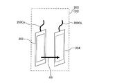
- the liquid level detection device shown in FIG. 20C is an ultrasonic vibration type liquid level detection sensor
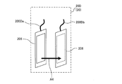
- the liquid level detection apparatus 20D shown in FIG. 4 is an optical liquid level detection sensor.
- the liquid level detection device 20A has two electric wires 200A, two electrodes 202A, and a heating element 201A.
- the left side of the drawing is illustrated as the electric wire 200 ⁇ / b> Aa
- the right side of the drawing is illustrated as the electric wire 200 ⁇ / b> Ab.
- the left side of the drawing is illustrated as an electrode 202Aa
- the right side of the drawing is illustrated as an electrode 202Ab.
- the heating element 201A is disposed between the electrode 202Aa and the electrode 202Ab.
- the electrode 202Aa and the electrode 202Ab are disposed so as to face each other, that is, face each other.
- a current is allowed to flow from the electrode 202Aa to the electrode 202Ab.
- a current flows between the electrode 202Aa and the electrode 202Ab as indicated by an arrow A1 in FIG. That is, in FIG. 1, a current vector (that is, a signal vector) between the electrode 202Aa and the electrode 202Ab is indicated by an arrow A1.
- Liquid level detection using an exothermic sensor comprises a sensor unit that includes two electrodes 202A and a heating element 201A.
- the sensor unit generates heat, and the liquid level is detected by judging gas and liquid based on the temperature response of the sensor unit. It is a method to do.
- the liquid level detection device 20A can be configured by, for example, an NTC sensor, a PTC sensor, or the like that utilizes a change in element resistance (electric resistance) depending on element temperature.
- NTC is an abbreviation for “negative temperature coefficient”
- PTC is an abbreviation for “positive temperature coefficient”.
- the heat generating element 201A generates heat by electric power supplied from the control device side.
- the heating element 201A has a certain relationship between its own heat (temperature) and its own resistance value. For example, when the heating element is used for a PTC sensor, a proportional relationship is established between its own temperature and the resistance value. Further, when the heating element is used for the NTC sensor, an inversely proportional relationship is established between its own temperature and the resistance value.
- the electrode 202A is composed of a plate-like member having a front surface and a back surface.
- the surface of the electrode 202Aa and the surface of the electrode 202Ab are arranged to face each other. That is, the back surface of the electrode 202Aa and the back surface of the electrode 202Ab are directed outward.
- the electrode 202Aa corresponds to the “first plate-like member” of the present invention.
- the electrode 202Ab corresponds to the “second plate-like member” of the present invention.
- the “surface opposite to the surface facing the second plate member” means the back surface of the electrode 202Aa which is the “first plate member”, and “surface facing the second plate member” It means the surface of the electrode 202Aa which is the “first plate member”.
- the heat generating element 201A generates heat by the supplied electric power, and has a size hidden by the electrode 202A. That is, when the liquid level detection device 20A is viewed from one side (back side) of the electrode 202A, the heating element 201A is covered with the electrode 202A and cannot be seen. In other words, the electrode 202A has an area covering the entire heating element 201A.
- the liquid level detection device 20A is connected to a control device (control device 50 shown in FIG. 15 at a later stage) via a wiring (electric wire 200A). Information output from the liquid level detection device 20A is input to the control device.
- a control device control device 50 shown in FIG. 15 at a later stage
- a wiring electric wire 200A
- Information output from the liquid level detection device 20A is input to the control device.
- FIG. 1 the state in which the liquid level detection device 20A is connected to the control device by wire is shown as an example, but the liquid level detection device 20A may be connected to the control device wirelessly.
- the liquid level detection device 20B has two electric wires 200B and two electrodes 202B.
- the left side of the drawing is illustrated as the electric wire 200Ba
- the right side of the drawing is illustrated as the electric wire 200Bb.
- the left side of the drawing is illustrated as an electrode 202Ba
- the right side of the drawing is illustrated as an electrode 202Bb.
- the electrode 202Ba and the electrode 202Bb are arranged to face each other, that is, to face each other.
- a current is allowed to flow from the electrode 202Ba to the electrode 202Bb.
- a current flows between the electrode 202Ba and the electrode 202Bb as indicated by an arrow A2 in FIG. That is, in FIG. 2, a current vector (that is, a signal vector) between the electrode 202Ba and the electrode 202Bb is indicated by an arrow A2.
- the liquid level detection using the capacitance type sensor includes, for example, a sensor unit configured by two electrodes 202B, energizes the sensor unit, and measures gas capacitance by measuring the capacitance of the electrode 202B. This is a method for detecting the liquid level.
- the electrode 202B is composed of a plate-like member having a front surface and a back surface.
- the surface of the electrode 202Ba and the surface of the electrode 202Bb are arranged to face each other. That is, the back surface of the electrode 202Ba and the back surface of the electrode 202Bb are directed outward.
- the electrode 202Ba corresponds to the “first plate-like member” of the present invention.
- the electrode 202Bb corresponds to the “second plate-like member” of the present invention.
- the “surface opposite to the surface facing the second plate member” means the back surface of the electrode 202Ba which is the “first plate member”, and the “surface facing the second plate member” is It means the surface of the electrode 202Ba which is the “first plate member”.
- the liquid level detection device 20B is connected to a control device (a control device 50 shown in FIG. 15 at a later stage) via a wiring (electric wire 200B). Information output from the liquid level detection device 20B is input to the control device.
- a state in which the liquid level detection device 20B is connected to the control device by wire is illustrated as an example, but the liquid level detection device 20B may be connected to the control device wirelessly.
- the liquid level detection device 20 ⁇ / b> C includes two electric wires 200 ⁇ / b> C, a wave transmitter 203, and a wave receiver 204.
- the left side of the drawing is illustrated as the electric wire 200 ⁇ / b> Ca
- the right side of the drawing is illustrated as the electric wire 200 ⁇ / b> Cb.
- the left side of the paper is illustrated as the transmitter 203 and the right side of the paper is illustrated as the receiver 204, but the positional relationship between the transmitter 203 and the receiver 204 may be reversed.
- the transmitter 203 and the receiver 204 are arranged so as to face each other, that is, face each other.
- Ultrasonic waves (or waves and vibrations may be used from the transmitter 203 to the receiver 204, and so on).
- an ultrasonic wave travels between the transmitter 203 and the receiver 204 as indicated by an arrow A3 in FIG. That is, in FIG. 3, the vector (that is, the signal vector) that the ultrasonic wave travels between the transmitter 203 and the receiver 204 is indicated by an arrow A3.
- the liquid level detection using the ultrasonic vibration type sensor includes, for example, a transmitter unit 203 and a receiver unit 204 that form a sensor unit, and the transmitter unit 203 transmits an ultrasonic wave, which is received by the receiver unit 204.
- This is a method of detecting the liquid level by receiving the gas and determining the gas-liquid according to the response at that time.
- the transmitter 203 and the receiver 204 are configured by plate members having a front surface and a back surface. Then, the surface of the transmitter 203 and the surface of the receiver 204 are arranged to face each other. That is, the back surface of the transmitter 203 and the back surface of the receiver 204 are each directed outward.
- the transmitter 203 corresponds to the “first plate member” of the present invention.
- the wave receiver 204 corresponds to the “second plate-like member” of the present invention.
- the “surface opposite to the surface facing the second plate member” means the back surface of the transmitter 203 which is the “first plate member”, and “surface facing the second plate member”. Means the surface of the transmitter 203 which is the “first plate-like member”.
- a reflector may be provided instead of the receiver 204, the ultrasonic wave may be reflected by the reflector, the ultrasonic wave may be received by the transmitter 203, and the gas-liquid may be discriminated.
- the transmitter 203 functions as a transmitter / receiver having not only the function of the transmitter 203 but also the function of the receiver 204.
- the liquid level detection device 20C is connected to a control device (a control device 50 shown in FIG. 15 at a later stage) via a wiring (electric wire 200C). Information output from the liquid level detection device 20C is input to the control device.
- a control device a control device 50 shown in FIG. 15 at a later stage
- a wiring electric wire 200C
- Information output from the liquid level detection device 20C is input to the control device.
- FIG. 3 the state in which the liquid level detection device 20C is connected to the control device by wire is shown as an example, but the liquid level detection device 20C may be connected to the control device wirelessly.
- the liquid level detection device 20 ⁇ / b> D has two electric wires 200 ⁇ / b> D, a light transmitter 205, and a light receiver 206.
- the left side of the drawing is illustrated as the electric wire 200Da
- the right side of the drawing is illustrated as the electric wire 200Db.
- the left side of the paper is illustrated as the light transmitter 205
- the right side of the paper is illustrated as the light receiver 206, but the positional relationship between the light transmitter 205 and the light receiver 206 may be reversed.
- the light transmitter 205 and the light receiver 206 are arranged to face each other, that is, to face each other.
- the light travels from the light transmitter 205 to the light receiver 206. At this time, light travels between the light transmitter 205 and the light receiver 206 as indicated by an arrow A4 in FIG. That is, in FIG. 4, a vector (that is, a signal vector) in which light travels between the light transmitter 205 and the light receiver 206 is indicated by an arrow A4.
- the liquid level detection using the optical sensor is configured by a light transmitter 205 and a light receiver 206 to form a sensor unit, and the light transmitter 205 emits light, which is received by the light receiver 206.
- the liquid level is detected by discriminating gas and liquid according to the light receiving state.
- the light transmitter 205 and the light receiver 206 are configured by plate members having a front surface and a back surface. Then, the surface of the light transmitter 205 and the surface of the light receiver 206 are arranged to face each other. That is, the back surface of the light transmitter 205 and the back surface of the light receiver 206 are directed outward.
- the light transmitter 205 corresponds to the “first plate-like member” of the present invention.
- the light receiver 206 corresponds to the “second plate-like member” of the present invention.
- the “surface opposite to the surface facing the second plate member” means the back surface of the light transmitter 205 which is the “first plate member”, and “surface facing the second plate member”. Means the surface of the light transmitter 205 which is the “first plate-like member”.
- a reflecting plate may be provided instead of the light receiving device 206, the light may be reflected by the reflecting plate, and the light transmitting device 205 may receive the light to discriminate the gas and liquid.
- the light transmitter 205 acts as a light transmitter / receiver having not only the function of the light transmitter 205 but also the function of the light receiver 206.
- the liquid level detection device 20D is connected to a control device (a control device 50 shown in FIG. 15 at a later stage) via a wiring (electric wire 200D).
- the information output from the liquid level detection device 20D is input to the control device.
- FIG. 4 the state in which the liquid level detection device 20D is connected to the control device by wire is shown as an example, but the liquid level detection device 20D may be connected to the control device wirelessly.
- FIGS. 5 are schematic configuration diagrams showing a schematic configuration example of the liquid reservoir 15 to which the liquid level detection device 20 is attached.
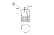
- the liquid reservoir 15 will be described with reference to FIGS. 5 is a liquid storage container 15A
- the liquid storage container 15 shown in FIG. 2 is a liquid storage container 15B
- the liquid storage container 15 shown in FIG. 3 is a liquid storage container 15C
- the container 15 will be described as a liquid storage container 15D.
- the liquid storage container 15 will be described.
- the liquid reservoir 15A is used as a configuration of an accumulator or a receiver, for example.
- the liquid reservoir 15 ⁇ / b> A has a cylindrical appearance, and is arranged so that the cylindrical axis is in the horizontal direction. That is, the liquid reservoir 15A is a horizontal container.
- the liquid storage container 15A can be constituted by a pressure container having a thickness of about 4 to 10 mm, for example.
- FIG. 5 schematically shows a state in which the liquid refrigerant L and the gas refrigerant G are present inside the liquid reservoir 15A.
- the liquid reservoir 15A has a container body 150A that can store the liquid refrigerant L.
- the liquid reservoir 15A has an inlet pipe 151 that is connected to the upper surface of the container body 150A and into which the refrigerant flows. Furthermore, the liquid reservoir 15A has an outlet pipe 152 that is connected to the upper surface portion of the container main body 150A and allows the refrigerant present in the container main body 150A to flow out.
- the liquid reservoir 15A is installed, for example, between an evaporator and a compressor constituting a refrigeration cycle.
- the refrigerant that has passed through the evaporator flows into the container main body 150A via the inlet pipe 151, and in the container main body 150A. It is separated into a liquid refrigerant L and a gas refrigerant G.
- the gas refrigerant G is lighter than the liquid refrigerant, flows above the container main body 150A, flows out of the container main body 150A through the outlet pipe 152, and is sucked into the compressor.
- the liquid refrigerant L is heavier than the gas refrigerant, flows below the container body 150A, and is stored at the bottom of the container body 150A.
- the liquid reservoir 15B is used as a configuration of, for example, an accumulator, a receiver, or an oil separator.
- the liquid storage container 15 ⁇ / b> B has a cylindrical appearance, and is arranged so that the cylindrical axis is in the vertical direction. That is, the liquid reservoir 15B is a vertical container.
- the liquid storage container 15B can be constituted by a pressure container having a thickness of about 4 to 10 mm, for example.
- FIG. 6 schematically shows a state in which the liquid refrigerant L and the gas refrigerant G are present inside the liquid reservoir 15B.
- the liquid storage container 15B is used as an oil separator, the refrigerating machine oil is stored instead of the liquid refrigerant L.
- the liquid reservoir container 15B has a container body 150B that can store the liquid refrigerant L or the refrigerating machine oil.
- the liquid reservoir 15B has an inlet pipe 151 that is connected to the upper surface of the container body 150B and into which the refrigerant flows.
- the liquid storage container 15B has an outlet pipe 152 that is connected to the upper surface portion of the container main body 150B and allows the refrigerant present in the container main body 150B to flow out.
- the liquid reservoir 15B is installed, for example, between an evaporator and a compressor constituting a refrigeration cycle.
- the refrigerant that has passed through the evaporator flows into the container main body 150B via the inlet pipe 151, and is stored in the container main body 150B. It is separated into a liquid refrigerant L and a gas refrigerant G.
- the gas refrigerant G is lighter than the liquid refrigerant, flows above the container body 150B, flows out of the container body 150B through the outlet pipe 152, and is sucked into the compressor.
- the liquid refrigerant L is heavier than the gas refrigerant, flows below the container body 150B, and is stored at the bottom of the container body 150B.
- the liquid reservoir 15B is installed, for example, on the discharge side of the compressor constituting the refrigeration cycle.
- the refrigerant discharged from the compressor flows into the container main body 150B through the inlet pipe 151, and the container main body 150B Swivel inside.
- the gas refrigerant G is lighter than the refrigerating machine oil, flows out from the oil separator through the outlet pipe 152, and flows into the condenser installed on the downstream side of the oil separator.
- the refrigerating machine oil is heavier than the gas refrigerant, dripped below the container body 150B, and stored at the bottom of the container body 150B.
- the liquid reservoir 15C is used as a configuration of a compressor or an oil separator, for example.
- the liquid reservoir 15 ⁇ / b> C has a cylindrical appearance, and is disposed such that the cylindrical axis is in the vertical direction. That is, the liquid reservoir 15C is a vertical container.
- the liquid storage container 15C can be constituted by a pressure container having a thickness of about 4 to 10 mm, for example.
- FIG. 7 schematically shows a state in which the refrigerant R and the refrigerating machine oil O exist inside the liquid reservoir 15C.
- the liquid reservoir container 15C has a container body 150C that can store the refrigerating machine oil O.
- the liquid reservoir 15C has an inlet pipe 151 that is connected to the side surface of the container body 150C and into which the refrigerant flows.
- the liquid storage container 15C has an outlet pipe 152 that is connected to the upper surface of the container main body 150C and allows the refrigerant present in the container main body 150C to flow out.
- the refrigerant R flows into the container body 150C through the inlet pipe 151, and the refrigeration oil O is supplied to the container body 150C. Separated from the refrigerant R. The refrigerant R from which the refrigerating machine oil O has been separated flows out of the container body 150C through the outlet pipe 152. On the other hand, the refrigerating machine oil O flows below the container body 150C and is stored at the bottom of the container body 150C.
- the liquid reservoir 15D is used as a configuration of a compressor or an oil separator, for example.
- the liquid reservoir 15 ⁇ / b> D has a cylindrical appearance and is arranged so that the cylindrical axis is in the vertical direction. That is, the liquid reservoir 15D is a vertical container.
- the liquid storage container 15D can be constituted by a pressure container having a thickness of about 4 to 10 mm, for example.
- FIG. 8 schematically shows a state where the refrigerant R and the refrigerating machine oil O are present in the liquid reservoir 15D.
- the liquid reservoir container 15D has a container body 150D that can store the refrigerating machine oil O.
- the liquid reservoir 15D has an inlet pipe 151 that is connected to the bottom surface of the container body 150D and into which the refrigerant flows.
- the liquid storage container 15D has an outlet pipe 152 that is connected to the upper surface of the container main body 150D and allows the refrigerant present in the container main body 150D to flow out.
- the refrigerant R flows into the container main body 150D through the inlet pipe 151, and the refrigerating machine oil O is supplied to the container main body 150D. Separated from the refrigerant R. The refrigerant R from which the refrigerating machine oil O is separated flows out of the container main body 150D through the outlet pipe 152. On the other hand, the refrigerating machine oil O flows below the container body 150D and is stored at the bottom of the container body 150D.
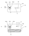
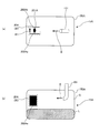
- FIG. 9 is a schematic diagram for explaining an example of a method of installing the liquid level detection device 20 in the horizontal container.
- FIG. 10 is a schematic diagram for explaining an example of a method of installing a liquid level detection device as a comparative example in a horizontal container.
- FIG. 9A is a diagram schematically showing a state in which the liquid storage container 15A is viewed from the bottom surface side
- FIG. 9B is a diagram schematically showing a state in which the liquid storage container 15A is viewed from the side surface. It is.
- FIG. 10A is a diagram schematically showing a state in which the reservoir 15A is viewed from the bottom side
- FIG. 10B is a diagram schematically showing a state in which the reservoir 15A is viewed from the side. It is.
- FIGS. 9 and 10 show an example in which the liquid level detection device 20A is installed in the liquid reservoir 15A which is the horizontal container shown in FIG. In FIGS. 9 and 10, the electric wire 200A and the outlet pipe 152 are not shown.
- the liquid level detection device 20A is installed inside the container body 150A of the liquid reservoir 15A.
- the liquid level detection device 20A is attached to, for example, a lower limit position and an upper limit position of a fluid (for example, a liquid refrigerant) stored in the container main body 150A.
- a fluid for example, a liquid refrigerant
- the installation number and installation position of the liquid level detection device 20A are not particularly limited, and may be appropriately determined depending on the application, volume, type of fluid to be stored, and the like of the liquid storage container 15 to be installed.
- the liquid reservoir 15A in which the liquid level detection device 20A shown in FIG. 9 is installed is an accumulator or receiver container.
- the refrigerant circulating in the refrigerant circuit provided in the refrigeration cycle apparatus flows into the container main body 150A, and the liquid refrigerant L is stored in the container main body 150A.
- the electrode 202Aa and the electrode 202Ab are arranged to face each other, and the electrode 202Aa is arranged so that the back surface of the electrode 202Aa is orthogonal to the fluid flow direction around the installation position of the liquid level detection device 20A.
- the liquid level detection device 20A includes the signal vector (arrow A1) flowing between the electrodes 202A and the fluid flowing into the liquid reservoir 15A and flowing around the liquid level detection device 20A.
- the streamline vector (arrow B) is installed in parallel.
- the back surface of the electrode 202Aa does not need to be strictly orthogonal to the fluid flow direction, and includes a slight deviation (range of ⁇ 10 °) (the liquid level detection device 20C to the liquid level detection device). The same applies to 20D).
- the liquid level detection device 20A by installing the liquid level detection device 20A, it is possible to prevent the liquid droplets flowing into the container body 150A from the inlet pipe 151 from being disturbed by the electrode 202A and coming into contact with the heating element 201A. That is, the electrode 202A has a function as a shielding part. Therefore, in the container main body 150A, the fluid flowing around the liquid level detection device 20A collides with the electrode 202A, the fluid flow is cut off, and does not reach the heating element 201A.
- FIG. 10 shows a state in which the electrodes 202Aa and 202Ab arranged opposite to each other are arranged in parallel with the fluid flow around the installation location of the liquid level detection device 20A as a comparative example. That is, in the installation example shown in FIG. 10, the liquid level detection device 20A includes a signal vector (arrow A1) that flows between the electrodes 202A and the fluid that flows into the liquid reservoir 15A and flows around the liquid level detection device 20A.
- the streamline vector (arrow B) is installed so as to be orthogonal.
- the liquid level detection device 20A when the liquid level detection device 20A is installed, the liquid droplets flowing into the container main body 150A from the inlet pipe 151 contact the heating element 201A without being obstructed by the electrode 202A. Therefore, the fluid reaches the heat generating element 201A. In such a case, the temperature response of the heat generating element 201A may change due to the influence of the droplet, and the liquid level detection device 20A may make an erroneous determination.
- the liquid level detection device 20A determines that the gas part is the liquid part because the droplet does not contact the heating element 201A. There is no false detection.
- the liquid level detection device 20A is installed as shown in FIG. 10, there is a high possibility that the droplet contacts the heating element 201A, and the liquid level detection device 20A is a gas part, even though the liquid level detection device 20A is a gas part. Depending on the purpose, it will be determined as a liquid part, that is, erroneous detection will occur.
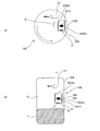
- FIG. 11 is a schematic diagram for explaining an example of a method of installing the liquid level detection device 20 in the vertical container.
- FIG. 12 is a schematic diagram for explaining an example of a method of installing a liquid level detection device as a comparative example in a vertical container.
- FIG. 11A is a diagram schematically showing a state in which the liquid storage container 15B is viewed from the bottom surface side
- FIG. 11B is a diagram schematically showing a state in which the liquid storage container 15B is viewed from the side surface.
- FIG. 12A is a diagram schematically showing a state in which the reservoir 15B is viewed from the bottom surface side
- FIG. 12B is a diagram schematically showing a state in which the reservoir 15B is viewed from the side. It is.
- FIGS. 11 and 12 show an example in which the liquid level detection device 20A is installed in the liquid reservoir 15B which is the vertical container shown in FIG. In FIGS. 11 and 12, the electric wire 200A and the outlet pipe 152 are not shown.
- the liquid level detection device 20A is installed inside the container body 150B of the liquid reservoir 15B.
- the liquid level detection device 20A is attached to, for example, a lower limit position and an upper limit position of a fluid (for example, liquid refrigerant) stored in the container main body 150B.
- a fluid for example, liquid refrigerant
- the installation number and installation position of the liquid level detection device 20A are not particularly limited, and may be appropriately determined depending on the application, volume, type of fluid to be stored, and the like of the liquid storage container 15 to be installed.
- the liquid reservoir 15B in which the liquid level detection device 20A shown in FIG. 11 is installed is an accumulator, receiver, or oil separator container.
- the refrigerant circulating in the refrigerant circuit included in the refrigeration cycle apparatus flows into the container main body 150B, and the liquid refrigerant L is stored in the container main body 150B. Since it is important to grasp the amount of refrigerant for efficient operation of the refrigeration cycle apparatus, the amount of refrigerant is grasped from the amount of liquid refrigerant L stored using the liquid level detection device 20.
- the refrigeration oil O flows into the container body 150B together with the refrigerant, is separated from the refrigerant R, and is stored in the bottom of the container body 150C. That is, the refrigerating machine oil O is discharged to the outside of the compressor together with the refrigerant R.
- the refrigerating machine oil O can be returned to the compressor, and the refrigerating machine oil O can be prevented from being exhausted from the compressor.
- the operation efficiency of the refrigeration cycle apparatus is reduced. Therefore, by detecting the liquid level of the refrigeration oil O using the liquid level detection device 20, the oil return timing to the compressor can be optimized, and the operating efficiency of the refrigeration cycle apparatus can be prevented from being lowered.
- the electrode 202Aa and the electrode 202Ab are arranged to face each other, and the electrode 202Aa is arranged so that its back surface is orthogonal to the flow direction of the fluid around the installation position of the liquid level detection device 20A. ing.
- the fluid flowing from the inlet pipe 151 into the container main body 150B of the liquid storage container 15B flows while swirling along the wall surface of the container main body 150A. Therefore, in the installation example shown in FIG. 11, the liquid level detection device 20A includes a signal vector (arrow A1) that flows between the electrodes 202A and a fluid that flows into the liquid reservoir 15A and flows around the liquid level detection device 20A.
- the streamline vector (arrow B) is installed in parallel.
- the liquid level detection device 20A by installing the liquid level detection device 20A, it is possible to prevent the liquid droplets flowing into the container body 150B from the inlet pipe 151 from being disturbed by the electrode 202A and coming into contact with the heating element 201A. That is, the electrode 202A has a function as a shielding part. Therefore, in the container main body 150B, the fluid flowing around the liquid level detection device 20A collides with the electrode 202A, the fluid flow is cut off, and does not reach the heating element 201A.
- FIG. 12 a state in which the electrodes 202Aa and 202Ab arranged opposite to each other are arranged in parallel with the fluid flow around the installation location of the liquid level detection device 20A is shown as a comparative example. That is, in the installation example shown in FIG. 12, the liquid level detection device 20A includes a signal vector (arrow A1) that flows between the electrodes 202A and a fluid that flows into the liquid reservoir 15B and flows around the liquid level detection device 20A.
- the streamline vector (arrow B) is installed so as to be orthogonal.
- the liquid level detection device 20A when the liquid level detection device 20A is installed, the liquid droplets flowing into the container main body 150B from the inlet pipe 151 are not disturbed by the electrode 202A and come into contact with the heating element 201A. Therefore, the fluid reaches the heat generating element 201A. In such a case, the temperature response of the heat generating element 201A may change due to the influence of the droplet, and the liquid level detection device 20A may make an erroneous determination.
- the liquid level detection device 20A determines that the gas part is the liquid part because the droplet does not contact the heating element 201A. There is no false detection.
- the liquid level detection device 20A is installed as shown in FIG. 12, there is a high possibility that the droplet contacts the heating element 201A, and the liquid level detection device 20A is a gas part, even though the liquid level detection device 20A is a gas part. Depending on the purpose, it will be determined as a liquid part, that is, erroneous detection will occur.
- a method (part 2) of installing the liquid level detection device 20 in the vertical container will be described taking the liquid level detection device 20A as an example.
- 13 and 14 are schematic views for explaining an example of a method for installing the liquid level detection device 20 in the vertical container. Arrows Z shown in FIGS. 13 and 14 indicate the direction of gravity.
- FIG. 13 shows an example in which the liquid level detection device 20A is installed in the liquid reservoir 15C which is the vertical container shown in FIG.
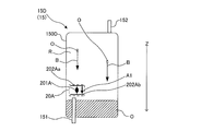
- FIG. 14 shows an example in which the liquid level detection device 20A is installed in the liquid reservoir 15D which is the vertical container shown in FIG.
- the electric wire 200A is not shown. 13 and 14 schematically show a state where the refrigerant R and the refrigerating machine oil O are present inside the container main body 150C and the container main body 150D.
- the liquid level detection device 20A is installed inside the container body 150C of the liquid reservoir 15C.
- the liquid level detection device 20A is attached to a lower limit position and an upper limit position of a fluid (for example, refrigerating machine oil or the like) stored in the container body 150C, for example.
- a fluid for example, refrigerating machine oil or the like
- the installation number and installation position of the liquid level detection device 20A are not particularly limited, and may be appropriately determined depending on the application, volume, type of fluid to be stored, and the like of the liquid storage container 15 to be installed.
- the liquid reservoir 15C in which the liquid level detection device 20A shown in FIG. 13 is installed is assumed to be a container used as a compressor or an oil separator.
- the refrigeration oil O flows into the container main body 150C together with the refrigerant, is separated from the refrigerant R, and is stored in the bottom of the container main body 150C (oil reservoir 115 shown in FIG. 16). Is done.
- the refrigerating machine oil O is supplied to sliding parts (bearing part, thrust bearing part, etc.) of a compressing part (compressing part 112 shown in FIG. 16) that compresses the refrigerant, lubricates the sliding part, and then the bottom part of the container body 150C.
- the refrigerator oil O is discharged together with the refrigerant R to the outside of the compressor.
- the sliding portion of the compression portion cannot be sufficiently lubricated. Therefore, by using the liquid level detection device 20 and detecting the liquid level of the refrigerating machine oil O, the amount of refrigerating machine oil O remaining in the compressor can be grasped.
- liquid reservoir 15C is used as an oil separator.
- the electrode 202Aa and the electrode 202Ab are arranged to face each other, and the electrode 202Aa is orthogonal to the flow direction of the refrigerating machine oil O dripping down from above the container body 150C. Is arranged.
- the refrigerating machine oil O used in the sliding part of the compressor or the refrigerating machine oil O separated from the refrigerant R drops from the upper side of the container main body 150C downward according to the gravity. Therefore, in the installation example shown in FIG. 13, the liquid level detection device 20A has a signal vector (arrow A1) that flows between the electrodes 202A and a streamline vector (arrow B) of the fluid that drops in the container body 150C. It is installed to be parallel.
- the liquid level detection device 20A by installing the liquid level detection device 20A, it is possible to prevent the liquid droplets dropped inside the container main body 150C from being disturbed by the electrode 202A and coming into contact with the heating element 201A. That is, the electrode 202A has a function as a shielding part. Therefore, in the container main body 150C, the fluid dripping toward the liquid level detection device 20A collides with the electrode 202A, the flow of the fluid is interrupted, and does not reach the heating element 201A.
- the liquid level detection device 20A determines that the gas part is the liquid part. There is no false detection.
- the liquid level detection device 20A is installed inside the container body 150D of the liquid reservoir container 15D.
- the liquid level detection device 20A is attached to, for example, a lower limit position and an upper limit position of a fluid (for example, refrigeration oil) stored in the container body 150D.
- a fluid for example, refrigeration oil
- the installation number and installation position of the liquid level detection device 20A are not particularly limited, and may be appropriately determined depending on the application, volume, type of fluid to be stored, and the like of the liquid storage container 15 to be installed.
- the liquid reservoir 15D in which the liquid level detection device 20A shown in FIG. 14 is installed is assumed to be a container used as an oil separator.
- the liquid storage container 15D may be used as a configuration of an accumulator or refrigerator oil. In this case, the detection target is not the refrigerator oil O but the liquid refrigerant.
- liquid reservoir 15D is used as an oil separator
- the electrode 202Aa and the electrode 202Ab are arranged to face each other, and the electrode 202Aa is orthogonal to the flow direction of the refrigerating machine oil O dripping from the upper side of the container main body 150D downward. Is arranged.
- the refrigerating machine oil O separated from the refrigerant R drops from the upper side to the lower side of the container body 150C according to gravity. Therefore, in the installation example shown in FIG. 14, the liquid level detection device 20A has a signal vector (arrow A1) that flows between the electrodes 202A and a streamline vector (arrow B) of the fluid that drops in the container body 150D. It is installed to be parallel.
- the liquid level detection device 20A by installing the liquid level detection device 20A, it is possible to prevent the liquid droplets dropped inside the container body 150D from being disturbed by the electrode 202A and coming into contact with the heating element 201A. That is, the electrode 202A has a function as a shielding part. Therefore, in the container main body 150D, the fluid dropped toward the liquid level detection device 20A collides with the electrode 202A, the fluid flow is cut off, and does not reach the heating element 201A.
- the liquid level detection device 20A determines that the gas part is the liquid part because the droplet does not contact the heating element 201A. There is no false detection.
- liquid level detection device 20A is installed in the liquid reservoir 15
- the first plate-like member (the electrode 202Aa, the electrode 202Ba, the wave transmitter 203, and the light transmitter 205) and the second plate disposed to face the first plate-like member.
- a plate member (electrode 202Ab, electrode 202Bb, wave receiver 204 (or reflector), light receiver 206 (or reflector)), and the back surface of the first plate member is in the liquid reservoir 15 Since the first plate-like member also serves as a shielding portion even when the liquid droplets are scattered, the first plate-like member also serves as a shielding portion. Therefore, it is possible to suppress erroneous determination.
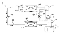
- FIG. FIG. 15 is a schematic configuration diagram showing an example of a refrigerant circuit configuration of a refrigeration cycle apparatus (hereinafter referred to as refrigeration cycle apparatus 1) according to Embodiment 2 of the present invention.
- the refrigerant circuit configuration and operation of the refrigeration cycle apparatus 1 will be described based on FIG.
- differences from the first embodiment will be mainly described, and the same parts as those in the first embodiment will be denoted by the same reference numerals and description thereof will be omitted.
- the refrigeration cycle apparatus 1 performs vapor compression refrigeration cycle operation, and the liquid level detection device 20 according to the first embodiment is configured to store fluid (for example, the compressor 11, the oil separator 16, the accumulator). 18, at least one of the receivers 35).
- fluid for example, the compressor 11, the oil separator 16, the accumulator. 18, at least one of the receivers 35).
- the refrigeration cycle apparatus 1 includes a compressor 11, a condenser 12, an expansion device 13, an evaporator 14, an accumulator 18, an oil separator 16, a liquid level detection device 20, and a control device 50. ing.
- the compressor 11, the condenser 12, the expansion device 13, and the evaporator 14 are connected by a refrigerant pipe 30 to form a refrigerant circuit.
- the oil separator 16 is provided on the refrigerant discharge side of the compressor 11, and the accumulator 18 is provided on the refrigerant suction side of the compressor 11.
- the compressor 11 is used for conveying a refrigerant.
- the compressor 11 has a function of compressing and discharging a gas refrigerant at a high temperature and a high pressure.
- the refrigerant suction side is connected to the accumulator 18, and the refrigerant discharge side is connected to the condenser 12.
- the condenser 12 is connected to the refrigerant discharge side of the compressor 11 via an oil separator 16.
- the compressor 11 can be comprised with an inverter compressor etc., for example.
- a rotary compressor, a scroll compressor, a screw compressor, a reciprocating compressor, or the like can be employed as the compressor 11.
- the oil separator 16 separates the refrigerating machine oil discharged together with the refrigerant from the compressor 11 and returns it to the suction side of the compressor 11 via the bypass valve 17.
- the oil separator 16 is a device that separates the discharge gas discharged from the compressor 11 and the refrigerating machine oil and returns only the refrigerating machine oil to the suction unit of the compressor 11.
- the lower side of the oil separator 16 and the suction side of the compressor 11 are connected by a bypass pipe 31.
- the bypass valve 17 is installed in the bypass pipe 31.
- the bypass valve 17 opens or closes the bypass pipe 31 to block or allow the refrigerant flow.
- the bypass valve 17 can be configured by, for example, an electromagnetic valve that can open and close the bypass pipe 31.
- the condenser 12 (heat radiator) condenses the refrigerant discharged from the compressor 11 into a high-pressure liquid refrigerant.
- the condenser 12 has an upstream side connected to the compressor 11 and a downstream side connected to the expansion device 13.
- the condenser 12 can be composed of, for example, a fin-and-tube heat exchanger or the like.
- the condenser 12 is provided with a blower 12 ⁇ / b> A that supplies air as a heat exchange medium to the condenser 12.
- the expansion device 13 expands the refrigerant that has passed through the condenser 12 to reduce the pressure.
- the expansion device 13 may be configured by an electric expansion valve or the like that can adjust the opening and adjust the flow rate of the refrigerant, for example.
- the expansion device 13 has an upstream side connected to the condenser 12 and a downstream side connected to the evaporator 14.
- the evaporator 14 evaporates the refrigerant depressurized by the expansion device 13 to form a gas refrigerant.
- the evaporator 14 has an upstream side connected to the expansion device 13 and a downstream side connected to the accumulator 18.
- the evaporator 14 can be configured by, for example, a fin-and-tube heat exchanger or the like.
- the evaporator 14 is provided with a blower 14 ⁇ / b> A that supplies air as a heat exchange medium to the evaporator 14.
- the accumulator 18 has a function of storing liquid refrigerant or the like.
- the accumulator 18 has an upstream side connected to the evaporator 14 and a downstream side connected to the suction side of the compressor 11.
- the receiver 35 has a function of storing a liquid refrigerant or the like, like the accumulator.
- the receiver 35 has an upstream side connected to the condenser 12 and a downstream side connected to the expansion device 13.
- the liquid level position of the liquid refrigerant stored in the liquid storage container 15 and the oil level position of the refrigerating machine oil stored in the container are detected.
- the liquid level detection device 20 is installed in at least one of the accumulator 18, the compressor 11, and the oil separator 16, for example. That is, the accumulator 18, the compressor 11, and the oil separator 16 have the function as the liquid reservoir 15 described in the first embodiment.
- FIG. 15 shows an example in which the liquid level detection device 20 is installed in all of the accumulator 18, the compressor 11, and the oil separator 16, but it may be installed in at least one of them.
- the control device 50 calculates the amount of liquid fluid stored in the container installed based on the detection result of the liquid level detection device 20.
- the control device 50 includes a power supply circuit unit that supplies voltage (electric power) to the liquid level detection device 20, an arithmetic circuit unit that calculates the temperature of the heating element 201A of the liquid level detection device 20, and the heating element 201A. And a storage unit that stores a predetermined table indicating the relationship between the resistance value and the temperature.
- the resistance value of the heat generating element 201A increases as the temperature of the heat generating element 201A increases.
- the temperature of the heating element 201A is lower than when the heating element 201A is in contact with the gas refrigerant.
- the resistance value of the heating element 201A also decreases correspondingly.
- the resistance value is higher than that in the case of touching the liquid refrigerant.
- the resistance value of the heating element 201A differs depending on whether the heating element 201A of the liquid level detection device 20 is in contact with the liquid refrigerant or the gas refrigerant. Therefore, the control device 50 detects the liquid level based on such information sent from the liquid level detection device 20.
- control device 50 calculates the resistance value of each of the heating elements 201A from the voltage value and current value supplied to each of the heating elements 201A. In addition, the control device 50 calculates each temperature using a predetermined table from each resistance value of the heating element 201A. Then, the control device 50 determines where the liquid level of the liquid reservoir 15A is based on the temperature of the heat generating element 201A.
- the control device 50 can determine whether or not the liquid refrigerant in the accumulator 18 overflows based on the detection result of the liquid level detection device 20. Further, the control device 50 can determine whether or not the refrigerant filled in the refrigerant circuit of the refrigeration cycle apparatus 1 is leaking. Furthermore, the control device 50 can calculate the charging amount of the refrigerant when charging the refrigerant after the refrigeration cycle apparatus 1 is installed.
- each actuator (drive component) is connected to the control device 50, and the control device 50 controls the operation of each actuator.
- the actuator include a compressor 11, a throttle device 13, a bypass valve 17, a blower 12A, a blower 14A, and the like.
- the control device 50 has a function of controlling the operation of each actuator based on detection values from various other sensors (not shown) in addition to the function of calculating the amount of liquid fluid.
- the control device 50 can be configured by hardware such as a circuit device that realizes the function, or can be configured by an arithmetic device such as a microcomputer or a CPU and software executed thereon.
- the blower 12A is mounted on the outdoor unit together with the condenser 12
- the blower 14A is mounted on the indoor unit together with the evaporator 14.
- the blower 12 ⁇ / b> A is used to supply heat to the condenser 12 and promote heat exchange between the refrigerant flowing through the condenser 12 and air.
- the blower 14 ⁇ / b> A is used to supply heat to the evaporator 14 and promote heat exchange between the refrigerant flowing through the evaporator 14 and the air.
- the condenser 12 is configured to exchange heat between water or brine and the refrigerant
- a pump for conveying water or brine or the like to the condenser 12 is installed instead of the blower 12A.
- the evaporator 14 is configured to exchange heat between water, brine, or the like and the refrigerant
- a pump that conveys water, brine, or the like to the evaporator 14 is installed instead of the blower 14A.
- the refrigeration cycle apparatus 1 is used as a hot water supply apparatus, an air-conditioning hot water supply combined apparatus, a refrigeration apparatus, etc., in addition to an air conditioner.
- the receiver 35 when the receiver 35 is provided, the receiver 35 may be provided on the downstream side of the condenser 12 as shown in FIG.
- the liquid level detection device 20 may be installed also in the receiver 35.
- the receiver 35 also has a function as the liquid reservoir 15 described in the first embodiment.
- the receiver 35 may be provided together with the accumulator 18, or only one of them may be provided.
- FIG. 16 is a schematic configuration diagram schematically showing the configuration of the compressor 11 that is one component of the refrigeration cycle apparatus 1. Based on FIG. 16, the installation location of the liquid level detection apparatus 20 in the compressor 11 is demonstrated. The liquid level detection by the liquid level detection device 20 is as described in the first embodiment.
- the compressor 11 has a suction part 110, a discharge part 111, a compression part 112, a motor part 113, a shaft / oil pump part 114, and an oil sump part 115.
- the suction part 110 corresponds to the inlet pipe 151 described in the first embodiment
- the discharge part 111 corresponds to the outlet pipe 152 described in the first embodiment.
- the gas refrigerant is sucked into the compressor 11 from the suction part 110.
- the gas refrigerant sucked into the compressor 11 is compressed by the compression unit 112 by the rotational force of the motor unit 113.
- the high-pressure and high-temperature gas refrigerant compressed by the compression unit 112 is discharged from the discharge unit 111.
- the refrigerating machine oil stored in the oil sump 115 is supplied to the compression part 112 through the shaft / oil pump part 114 in order to reduce the friction of the sliding part of the compression part 112. ing.
- the motor unit 113 will be filled with refrigerating machine oil and the rotational efficiency will be reduced.
- the amount of the refrigerating machine oil is too small, the compression unit 112 refrigerating machine oil cannot be supplied, and the friction increases, which may cause a failure. For this reason, it is desirable to control the refrigerating machine oil to an appropriate amount. Therefore, in the refrigeration cycle apparatus 1, the liquid level detection device 20 is installed in the oil reservoir 115 of the compressor 11 in order to grasp the appropriate amount of refrigeration oil. For example, as shown in FIG. 16, the two liquid level detection devices 20 may be installed at the lower limit position and the upper limit position of the oil sump 115.
- the installation location of the liquid level detection device 20 in the accumulator 18 is not particularly limited, for example, two liquid level detection devices 20 may be installed at the lower limit position and the upper limit position of the accumulator 18.
- three or more liquid level detection devices 20 may be arranged side by side in the vertical direction.
- the first plate member and the second plate member constituting the liquid level detection device 20 are extended in the vertical direction to detect a plurality of liquid levels. You may make it do.
- high-temperature and high-pressure gaseous refrigerant is discharged from the compressor 11.
- the high-temperature and high-pressure gas refrigerant (single phase) discharged from the compressor 11 flows into the condenser 12 through the oil separator 16.
- the condenser 12 heat exchange is performed between the flowing high-temperature and high-pressure gas refrigerant and the air supplied by the blower 12A, and the high-temperature and high-pressure gas refrigerant is condensed to a high-pressure liquid refrigerant (single phase). become.
- the high-pressure liquid refrigerant sent out from the condenser 12 is converted into a two-phase refrigerant consisting of a low-pressure gas refrigerant and a liquid refrigerant by the expansion device 13.
- the two-phase refrigerant flows into the evaporator 14.
- heat exchange is performed between the refrigerant flowing in the two-phase state and the air supplied by the blower 14 ⁇ / b> A, and the liquid refrigerant evaporates out of the refrigerant in the two-phase state, and the low-pressure gas refrigerant ( Single phase).
- the low-pressure gas refrigerant sent out from the evaporator 14 flows into the compressor 11 via the accumulator 18, is compressed to become a high-temperature high-pressure gas refrigerant, and is discharged from the compressor 11 again. Thereafter, this cycle is repeated.
- the case where the exothermic liquid level detection sensor (the liquid level detection device 20A according to the first embodiment) is used as the liquid level detection device 20 has been described as an example.
- Liquid level detection sensor liquid level detection device 20B according to the first embodiment
- ultrasonic vibration type liquid level detection sensor liquid level detection device 20C according to the first embodiment
- optical liquid level detection sensor Even when the liquid level detection device 20D according to Embodiment 1 is used, the liquid level can be detected in the same manner. Even in these liquid level detection devices, the measurement value in the sensor unit differs depending on whether there is liquid or gas in the sensor unit (first plate member and second plate member). The gas-liquid can be judged by the value.
- the control device 50 calculates the temperature from the resistance value.
- the present invention is not limited to this.
- the control apparatus 50 may compare the resistance value of the heat generating element 201A without converting it into temperature.
- the heating element 201A has been described as having both a function as a heat generating element and a function as an element whose resistance changes.
- the present invention is not limited to this, and both functions are separated. You may make it bear in the composition of.
- the liquid level detection device 20A can be configured by providing, in place of the heating element 201A, a heating body and a temperature sensor attached to the heating body separately from the heating body.
- a thermistor can be used as the temperature sensor.
- a resistor etc. are employable, for example. And self can be heated by supplying with electricity to a resistor.
- the refrigeration cycle apparatus 1 includes the liquid level detection device 20 according to Embodiment 1, the first plate member serves as a blocking plate, and the fluid does not directly contact the heating element 201A. It can suppress that detection accuracy falls.
- the first plate member serves as a blocking plate, and the fluid is between the first plate member and the second plate member. Since the liquid does not flow, the liquid level detection accuracy is not reduced.
- the sensor unit of the liquid level detection device 20 has been described as an example in which the sensor unit is a single unit (a pair of the first plate member and the second plate member), but the configuration is not limited thereto. For example, a plurality of sensor units may be provided.
- the liquid level detection device 20 can also be used as an overflow detection technology sensor that detects that the liquid refrigerant overflows from the accumulator 18, and can suppress the return of the liquid refrigerant to the compressor 11. If it does in this way, failure of compressor 11 can be controlled and the reliability of compressor 11 can be raised.
- the refrigeration cycle apparatus 1 can accurately grasp the amount of liquid in the accumulator 18 when the refrigerant is charged after the refrigerant circuit is installed in a building or the like, the refrigerant circuit is not overfilled with the refrigerant.
- refrigerant leakage can be detected and dealt with early, and global warming can be suppressed. Can do. Further, it is possible to detect refrigerant leakage such as combustible refrigerant at an early stage, and to prevent occurrence of serious accidents such as combustion and explosion, for example.
- liquid level detection device 20 makes a false detection, there are the following inconveniences, and the refrigeration cycle device 1 may not be able to operate normally, and it may lead to equipment failure.
- the liquid level detection device 20 installed in the accumulator 18 erroneously detects the gas part as the liquid part
- the liquid refrigerant stored in the accumulator 18 is stored in the condenser 12 on the high pressure side.
- the degree of superheat at the outlet is increased, and the superheated gasified refrigerant flows into the accumulator 18.
- more liquid refrigerant than necessary is collected in the condenser 12, so that the high pressure rises, the high pressure becomes abnormal, and normal operation cannot be performed.
- the liquid level detection device 20 that detects the oil level of the refrigerating machine oil of the compressor 11 erroneously detects the gas part as the liquid part, the compressor 11 is in a state where there is not much refrigerating machine oil in the compressor 11. Control to reduce internal refrigeration oil will be performed. Therefore, it becomes impossible to secure the refrigerating machine oil necessary for the lubrication of the compressor 11, and the sliding portion of the compressor 11 is burned, causing a compressor failure.
- the receiver 35 may be installed on the high-pressure side of the refrigerant circuit of the refrigeration cycle apparatus 1, and the liquid level detection device 20 may be installed on the receiver 35. Further, when a plurality of liquid level detection devices 20 are installed, all of them may be the same type of liquid level detection device 20, all types of liquid level detection devices 20 may be combined, or some may be the same type.
- the liquid level detection device 20 may be used. That is, when the lower limit liquid level of the liquid refrigerant stored in the accumulator 18 is detected, the liquid level detection device 20D according to the first embodiment is used. You may utilize the liquid level detection apparatus 20B which concerns on the form 1.
- the liquid level detection result by sending the liquid level detection result to the management center or the like, the liquid level can be detected remotely at any time. Therefore, it is possible to cope with sudden refrigerant leakage immediately before an abnormality such as damage to the equipment or a decrease in capability occurs, and it is possible to suppress the progression of refrigerant leakage as much as possible. Thereby, the reliability of the refrigeration cycle apparatus 1 can be improved, and deterioration of the environmental state due to the outflow of refrigerant can be prevented as much as possible.
- Refrigeration cycle device 11 compressor, 12 condenser, 12A blower, 13 throttling device, 14 evaporator, 14A blower, 15 liquid reservoir, 15A liquid reservoir, 15B liquid reservoir, 15C liquid reservoir, 15D liquid reservoir Container, 16 Oil separator, 17 Bypass valve, 18 Accumulator, 20 Liquid level detection device, 20A Liquid level detection device, 20B Liquid level detection device, 20C Liquid level detection device, 20D Liquid level detection device, 30 Refrigerant piping, 31 Bypass piping , 35 receiver, 50 control device, 110 suction section, 111 discharge section, 112 compression section, 113 motor section, 114 oil pump section, 115 oil sump section, 150A container body, 150B container body, 150C container body, 150D container body, 151 Inlet pipe, 152 Outlet pipe 200A electric wire, 200Aa electric wire, 200Ab electric wire, 200B electric wire, 200Ba electric wire, 200Bb electric wire, 200C electric wire, 200Ca electric wire, 200C
Landscapes
- Physics & Mathematics (AREA)
- Engineering & Computer Science (AREA)
- Thermal Sciences (AREA)
- Fluid Mechanics (AREA)
- General Physics & Mathematics (AREA)
- Power Engineering (AREA)
- Electromagnetism (AREA)
- Mechanical Engineering (AREA)
- General Engineering & Computer Science (AREA)
- Chemical & Material Sciences (AREA)
- Analytical Chemistry (AREA)
- Acoustics & Sound (AREA)
- Measurement Of Levels Of Liquids Or Fluent Solid Materials (AREA)
Abstract
液面検知装置は、容器内に設けられ、該容器に貯留される流体の液面を検知するものであって、板状に形成された第1板状部材と、板状に形成され、第1板状部材に対向配置される第2板状部材と、を有し、第1板状部材は、第2板状部材と対向する面の反対側の面が、容器内における第1板状部材の周囲の流体の流れ方向と直交するように配置されるものである。
Description
本発明は、容器内に貯留される流体の液面位置を検知する液面検知装置、及び、この液面検知装置を備えた冷凍サイクル装置に関するものである。
従来の液溜め容器の中には、液溜め容器内に貯留された液体の液面の高さ位置を検出するのに利用される液面検出センサを有するものが存在している(例えば、特許文献1参照)。
特許文献1に記載の液溜め容器及び液面検出機構は、液体及び気体が収容される容器と、その上端部が容器の上面部に接続されて固定された支持材と、支持材の下端部に取り付けられた発熱抵抗体と、発熱抵抗体の両端にかかる電圧を検出する電圧計とを有しているものである。
発熱抵抗体が容器内の液面に浸漬しているときと、発熱抵抗体が液面に浸漬しておらず気体に接触しているときとでは、電圧計で検出される電圧値が異なる。そこで、特許文献1に記載の技術では、発熱抵抗体(発熱素子)が液面に浸漬しているか否かにより相違する電圧値に基づいて、液面を検出するようにしている。
また、受液器内の冷媒に浸した対向極板からなる静電容量センサと、このセンサの静電容量検出値を発振周波数に変換する静電容量変換手段と、からなり、静電容量変換手段の発信周波数を冷媒の液面高さに換算し、液面高さを判定するようにした液面検出センサが存在している(例えば、特許文献2参照)。
また、空気調和装置のレシーバあるいはアキュムレータの側面に、複数個の超音波センサを一列に配列した超音波センサアレイを装着して、超音波の受信信号から液冷媒の有無を識別するようにした液面検出センサが存在している(例えば、特許文献3参照)。
また、レーザー光を液面へ所定角度で発射するレーザー光線発射装置と、液面へ入射し屈折したレーザー光を受光する光センサとを設けて、光センサによるレーザー光の受光の有無からレベルが正常液面レベル範囲か否かを検知するセンサが存在している(例えば、特許文献4参照)。
ここで、液溜め容器が冷凍サイクル装置に搭載され、液溜め容器に貯留される流体の液面を検知する手段として上記のタイプのセンサを用いた場合について考える。液溜め容器に流入する流体は、ガス冷媒が主であるが、液滴状の液冷媒、冷凍機油が混在している場合が多い。
特許文献1に記載されているような発熱式液面検知センサでは、液溜め容器内のガス部に液滴が混在する場合、ガス部の発熱素子の放熱が促進され、ガス部の素子温度と、液冷媒に浸漬しているときの発熱素子の温度が、同一又は近い値となってしまい、ガス部を液部と誤判定してしまう可能性がある。
特許文献2に記載されているような静電容量式液面検知センサでは、液滴の影響により静電容量が変化し、ガス部であるのに液部と誤判定してしまうという可能性がある。
特許文献3に記載されているような超音波式液面検知センサでは、液滴の影響により超音波信号(又は、波動信号、振動信号でもよい)が変化してしまい、誤検知してしまう可能性がある。
特許文献4に記載されているような光式液面検知センサでは、液滴の影響により光が散乱してしまい、誤判定してしまう可能性がある。
本発明は、以上のような課題を解決するためになされたもので、ガス部と液部との誤検知を抑制し、液面位置の検出精度を向上させた液面検知装置及び冷凍サイクル装置を提供することを目的としている。
本発明に係る液面検知装置は、容器内に設けられ、該容器に貯留される流体の液面を検知する液面検知装置であって、板状に形成された第1板状部材と、板状に形成され、前記第1板状部材に対向配置される第2板状部材と、を有し、前記第1板状部材は、前記第2板状部材と対向する面の反対側の面が、前記容器内における前記第1板状部材の周囲の流体の流れ方向と直交するように配置されるものである。
本発明に係る冷凍サイクル装置は、圧縮機、凝縮器、絞り装置、蒸発器、アキュムレータを配管接続した冷媒回路を有し、上記の液面検知装置は、前記アキュムレータを構成している容器の内部に設置され、該容器に貯留される液冷媒の液面位置を検知するものである。
本発明に係る液面検知装置によれば、第1板状部材の第2板状部材と対向する面の反対側の面が、容器内における第1板状部材の周囲の流体の流れ方向と直交しているので、第1板状部材が遮蔽部を兼ねることになり、液滴の影響を受けず、誤判定が抑制できる。
本発明に係る冷凍サイクル装置によれば、上記の液面検知装置をアキュムレータに設置しているので、液滴がガス部を飛散している状態であっても、誤判定が抑制された液面検知が実現できる。
以下、図面に基づいて本発明の実施の形態について説明する。なお、図1を含め、以下の図面では各構成部材の大きさの関係が実際のものとは異なる場合がある。また、図1を含め、以下の図面において、同一の符号を付したものは、同一又はこれに相当するものであり、このことは明細書の全文において共通することとする。さらに、明細書全文に表わされている構成要素の形態は、あくまでも例示であって、これらの記載に限定されるものではない。
実施の形態1.
図1~図4は、本発明の実施の形態1に係る液面検知装置20の概略構成例を示す概略構成図である。図1~図4に基づいて、液面検知装置20について説明する。なお、図1に示す液面検知装置20を液面検知装置20A、図2に示す液面検知装置20を液面検知装置20B、図3に示す液面検知装置20を液面検知装置20C、図4に示す液面検知装置20を液面検知装置20Dとそれぞれ称して説明する。また、液面検知装置20A~液面検知装置20Dを特に区別する必要がない場合には、液面検知装置20として説明する。
図1~図4は、本発明の実施の形態1に係る液面検知装置20の概略構成例を示す概略構成図である。図1~図4に基づいて、液面検知装置20について説明する。なお、図1に示す液面検知装置20を液面検知装置20A、図2に示す液面検知装置20を液面検知装置20B、図3に示す液面検知装置20を液面検知装置20C、図4に示す液面検知装置20を液面検知装置20Dとそれぞれ称して説明する。また、液面検知装置20A~液面検知装置20Dを特に区別する必要がない場合には、液面検知装置20として説明する。
液面検知装置20は、検知対象の流体が貯留される容器内に設置され、容器内に貯留される流体の液面位置を検出するものである。容器としては、例えば、冷凍サイクル装置に搭載されるアキュムレータを構成する容器、レシーバを構成する容器、圧縮機を構成する容器、オイルセパレータを構成する容器などがある。なお、冷凍サイクル装置については、実施の形態2で説明するものとする。
アキュムレータは、冷凍サイクル装置が備える冷媒回路の低圧側に設置されるものである。レシーバは、冷凍サイクル装置が備える冷媒回路の中圧側又は高圧側に設置されるものである。圧縮機は、冷凍サイクル装置が備える冷媒回路の一構成要素となるものである。オイルセパレータは、冷凍サイクル装置が備える圧縮機の吐出側に設けられるものである。
アキュムレータ及びレシーバは、容器を構成として備え、冷媒回路を循環する冷媒が液冷媒として貯留されるものである。アキュムレータ又はレシーバに液面検知装置20を取り付ける場合、液冷媒が液面検知装置20の検知対象となる。
圧縮機は、容器を構成として備え、容器内の摺動部で利用される冷凍機油が貯留されるものである。圧縮機に液面検知装置20を取り付ける場合、冷凍機油が液面検知装置20の検知対象となる。
オイルセパレータは、容器を構成として備え、冷媒とともに吐出された冷凍機油が貯留されるものである。オイルセパレータに液面検知装置20を取り付ける場合、冷凍機油が液面検知装置20の検知対象となる。
圧縮機は、容器を構成として備え、容器内の摺動部で利用される冷凍機油が貯留されるものである。圧縮機に液面検知装置20を取り付ける場合、冷凍機油が液面検知装置20の検知対象となる。
オイルセパレータは、容器を構成として備え、冷媒とともに吐出された冷凍機油が貯留されるものである。オイルセパレータに液面検知装置20を取り付ける場合、冷凍機油が液面検知装置20の検知対象となる。
液面検知装置20としては、発熱式の液面検知センサ、静電容量式の液面検知センサ、超音波振動式の液面検知センサ、あるいは、光式の液面検知センサがある。図1に示す液面検知装置20Aが発熱式の液面検知センサであり、図2に示す液面検知装置20Bが静電容量式の液面検知センサであり、図3に示す液面検知装置20Cが超音波振動式の液面検知センサであり、図4に示す液面検知装置20Dが光式の液面検知装置センサである。まず、それぞれの液面検知装置20の構成について説明する。
<液面検知装置20A>
図1に示すように、液面検知装置20Aは、2本の電線200Aと、2枚の電極202Aと、発熱素子201Aと、を有している。図1では、2本の電線200Aのうち、紙面左側を電線200Aa、紙面右側を電線200Abとして図示している。また、図1では、2枚の電極202Aのうち、紙面左側を電極202Aa、紙面右側を電極202Abとして図示している。発熱素子201Aは、電極202Aaと電極202Abとの間に配置される。電極202Aaと電極202Abとは、互いに向かい合うように、つまり対向配置されている。
図1に示すように、液面検知装置20Aは、2本の電線200Aと、2枚の電極202Aと、発熱素子201Aと、を有している。図1では、2本の電線200Aのうち、紙面左側を電線200Aa、紙面右側を電線200Abとして図示している。また、図1では、2枚の電極202Aのうち、紙面左側を電極202Aa、紙面右側を電極202Abとして図示している。発熱素子201Aは、電極202Aaと電極202Abとの間に配置される。電極202Aaと電極202Abとは、互いに向かい合うように、つまり対向配置されている。
例えば、電極202Aaから電極202Abに電流が流れるようにする。このとき、電極202Aaと電極202Abとの間には、図1の矢印A1で示されるように電流が流れる。つまり、図1では、電極202Aaと電極202Abとの間における電流のベクトル(つまり信号ベクトル)を、矢印A1で示している。
発熱式のセンサを用いた液面検知は、2つの電極202A、発熱素子201Aでセンサ部を構成し、発熱素子を発熱させ、センサ部の温度応答により気液を判断することで液面検知を行う方式である。液面検知装置20Aは、例えば、素子温度により素子抵抗(電気抵抗)が変化することを利用したNTCセンサ、あるいはPTCセンサなどで構成することができる。
なお、NTCとは、「negative temperature coefficient」の略であり、PTCとは、「positive temperature coefficient」の略である。
なお、NTCとは、「negative temperature coefficient」の略であり、PTCとは、「positive temperature coefficient」の略である。
発熱素子201Aは、制御装置側から供給される電力により発熱する。発熱素子201Aは、自身の有する熱(温度)と自身の抵抗値との間に一定の関連性を有している。例えば、発熱素子をPTCセンサに利用する場合、自身の温度と抵抗値との間には比例関係が成立する。また、発熱素子をNTCセンサに利用する場合、自身の温度と抵抗値との間には反比例の関係が成立する。
電極202Aは、表面及び背面を有した板状部材で構成されている。そして、電極202Aaの表面と、電極202Abの表面と、を対向配置させている。つまり、電極202Aaの背面と、電極202Abの背面と、がそれぞれ外側を向くようになっている。
電極202Aaが、本発明の「第1板状部材」に相当する。
電極202Abが、本発明の「第2板状部材」に相当する。
また、「第2板状部材と対向する面の反対側の面」とは「第1板状部材」である電極202Aaの背面を意味し、「第2板状部材と対向する面」とは「第1板状部材」である電極202Aaの表面を意味している。
電極202Aaが、本発明の「第1板状部材」に相当する。
電極202Abが、本発明の「第2板状部材」に相当する。
また、「第2板状部材と対向する面の反対側の面」とは「第1板状部材」である電極202Aaの背面を意味し、「第2板状部材と対向する面」とは「第1板状部材」である電極202Aaの表面を意味している。
発熱素子201Aは、供給された電力により発熱するものであり、電極202Aに隠れる大きさで構成されている。つまり、液面検知装置20Aを電極202Aの一面側(背面側)から見た場合、発熱素子201Aは、電極202Aに覆われて見えないようになっている。言い換えれば、電極202Aは、発熱素子201Aの全体を覆う面積を有している。
液面検知装置20Aは、配線(電線200A)を介して制御装置(後段の図15に示す制御装置50)に接続されている。制御装置には、液面検知装置20Aから出力された情報が入力されるようになっている。なお、図1では、液面検知装置20Aが有線で制御装置と接続されている状態を一例に示しているが、液面検知装置20Aが無線で制御装置と接続されていてもよい。
<液面検知装置20B>
図2に示すように、液面検知装置20Bは、2本の電線200Bと、2枚の電極202Bと、を有している。図2では、2本の電線200Bのうち、紙面左側を電線200Ba、紙面右側を電線200Bbとして図示している。また、図2では、2枚の電極202Bのうち、紙面左側を電極202Ba、紙面右側を電極202Bbとして図示している。電極202Baと電極202Bbとは、互いに向かい合うように、つまり対向配置されている。
図2に示すように、液面検知装置20Bは、2本の電線200Bと、2枚の電極202Bと、を有している。図2では、2本の電線200Bのうち、紙面左側を電線200Ba、紙面右側を電線200Bbとして図示している。また、図2では、2枚の電極202Bのうち、紙面左側を電極202Ba、紙面右側を電極202Bbとして図示している。電極202Baと電極202Bbとは、互いに向かい合うように、つまり対向配置されている。
例えば、電極202Baから電極202Bbに電流が流れるようにする。このとき、電極202Baと電極202Bbとの間には、図2の矢印A2で示されるように電流が流れる。つまり、図2では、電極202Baと電極202Bbとの間における電流のベクトル(つまり信号ベクトル)を、矢印A2で示している。
静電容量式のセンサを用いた液面検知は、例えば2つの電極202Bでセンサ部を構成し、センサ部に通電し、電極202Bの静電容量を計測することで気液を判別することで液面検知を行う方式である。
電極202Bは、表面及び背面を有した板状部材で構成されている。そして、電極202Baの表面と、電極202Bbの表面と、を対向配置させている。つまり、電極202Baの背面と、電極202Bbの背面と、がそれぞれ外側を向くようになっている。
電極202Baが、本発明の「第1板状部材」に相当する。
電極202Bbが、本発明の「第2板状部材」に相当する。
また、「第2板状部材と対向する面の反対側の面」とは「第1板状部材」である電極202Baの背面を意味し、「第2板状部材と対向する面」とは「第1板状部材」である電極202Baの表面を意味している。
電極202Baが、本発明の「第1板状部材」に相当する。
電極202Bbが、本発明の「第2板状部材」に相当する。
また、「第2板状部材と対向する面の反対側の面」とは「第1板状部材」である電極202Baの背面を意味し、「第2板状部材と対向する面」とは「第1板状部材」である電極202Baの表面を意味している。
液面検知装置20Bは、配線(電線200B)を介して制御装置(後段の図15に示す制御装置50)に接続されている。制御装置には、液面検知装置20Bから出力された情報が入力されるようになっている。なお、図2では、液面検知装置20Bが有線で制御装置と接続されている状態を一例に示しているが、液面検知装置20Bが無線で制御装置と接続されていてもよい。
<液面検知装置20C>
図3に示すように、液面検知装置20Cは、2本の電線200Cと、送波器203と、受波器204と、を有している。図3では、2本の電線200Cのうち、紙面左側を電線200Ca、紙面右側を電線200Cbとして図示している。また、図3では、紙面左側を送波器203、紙面右側を受波器204として図示しているが、送波器203と受波器204との位置関係を逆にしてもよい。送波器203と受波器204とは、互いに向かい合うように、つまり対向配置されている。
図3に示すように、液面検知装置20Cは、2本の電線200Cと、送波器203と、受波器204と、を有している。図3では、2本の電線200Cのうち、紙面左側を電線200Ca、紙面右側を電線200Cbとして図示している。また、図3では、紙面左側を送波器203、紙面右側を受波器204として図示しているが、送波器203と受波器204との位置関係を逆にしてもよい。送波器203と受波器204とは、互いに向かい合うように、つまり対向配置されている。
送波器203から受波器204に超音波(又は、波動、振動でもよい。以下も同様)が進むようにする。このとき、送波器203と受波器204との間には、図3の矢印A3で示されるように超音波が進む。つまり、図3では、送波器203と受波器204との間における超音波の進むベクトル(つまり信号ベクトル)を、矢印A3で示している。
超音波振動式のセンサを用いた液面検知は、例えば、送波器203及び受波器204でセンサ部を構成し、送波器203で超音波を発信し、それを受波器204で受信して、そのときの応答により気液を判別することで液面検知を行う方式である。
送波器203及び受波器204は、表面及び背面を有した板状部材で構成されている。そして、送波器203の表面と、受波器204の表面と、を対向配置させている。つまり、送波器203の背面と、受波器204の背面と、がそれぞれ外側を向くようになっている。
送波器203が、本発明の「第1板状部材」に相当する。
受波器204が、本発明の「第2板状部材」に相当する。
また、「第2板状部材と対向する面の反対側の面」とは「第1板状部材」である送波器203の背面を意味し、「第2板状部材と対向する面」とは「第1板状部材」である送波器203の表面を意味している。
送波器203が、本発明の「第1板状部材」に相当する。
受波器204が、本発明の「第2板状部材」に相当する。
また、「第2板状部材と対向する面の反対側の面」とは「第1板状部材」である送波器203の背面を意味し、「第2板状部材と対向する面」とは「第1板状部材」である送波器203の表面を意味している。
なお、受波器204の代わりに反射板を設け、超音波を反射板で反射させ、送波器203で超音波を受信し、気液を判別するようにしてもよい。この場合、送波器203が、送波器203の機能だけでなく、受波器204の機能を有する送受波器として作用することになる。
液面検知装置20Cは、配線(電線200C)を介して制御装置(後段の図15に示す制御装置50)に接続されている。制御装置には、液面検知装置20Cから出力された情報が入力されるようになっている。なお、図3では、液面検知装置20Cが有線で制御装置と接続されている状態を一例に示しているが、液面検知装置20Cが無線で制御装置と接続されていてもよい。
<液面検知装置20D>
図4に示すように、液面検知装置20Dは、2本の電線200Dと、送光器205と、受光器206と、を有している。図4では、2本の電線200Dのうち、紙面左側を電線200Da、紙面右側を電線200Dbとして図示している。また、図4では、紙面左側を送光器205、紙面右側を受光器206として図示しているが、送光器205と受光器206との位置関係を逆にしてもよい。送光器205と受光器206とは、互いに向かい合うように、つまり対向配置されている。
図4に示すように、液面検知装置20Dは、2本の電線200Dと、送光器205と、受光器206と、を有している。図4では、2本の電線200Dのうち、紙面左側を電線200Da、紙面右側を電線200Dbとして図示している。また、図4では、紙面左側を送光器205、紙面右側を受光器206として図示しているが、送光器205と受光器206との位置関係を逆にしてもよい。送光器205と受光器206とは、互いに向かい合うように、つまり対向配置されている。
送光器205から受光器206に光が進むようにする。このとき、送光器205と受光器206との間には、図4の矢印A4で示されるように光が進む。つまり、図4では、送光器205と受光器206との間における光の進むベクトル(つまり信号ベクトル)を、矢印A4で示している。
光式のセンサを用いた液面検知は、例えば、送光器205及び受光器206でセンサ部を構成し、送光器205で光を発光し、それを受光器206で受光して、そのときの受光状態により気液を判別することで液面検知を行う方式である。
送光器205及び受光器206は、表面及び背面を有した板状部材で構成されている。そして、送光器205の表面と、受光器206の表面と、を対向配置させている。つまり、送光器205の背面と、受光器206の背面と、がそれぞれ外側を向くようになっている。
送光器205が、本発明の「第1板状部材」に相当する。
受光器206が、本発明の「第2板状部材」に相当する。
また、「第2板状部材と対向する面の反対側の面」とは「第1板状部材」である送光器205の背面を意味し、「第2板状部材と対向する面」とは「第1板状部材」である送光器205の表面を意味している。
送光器205が、本発明の「第1板状部材」に相当する。
受光器206が、本発明の「第2板状部材」に相当する。
また、「第2板状部材と対向する面の反対側の面」とは「第1板状部材」である送光器205の背面を意味し、「第2板状部材と対向する面」とは「第1板状部材」である送光器205の表面を意味している。
なお、受光器206の代わりに反射板を設け、光を反射板で反射させ、送光器205で光を受光し、気液を判別するようにしてもよい。この場合、送光器205が、送光器205の機能だけでなく、受光器206の機能を有する送受光器として作用することになる。
液面検知装置20Dは、配線(電線200D)を介して制御装置(後段の図15に示す制御装置50)に接続されている。制御装置には、液面検知装置20Dから出力された情報が入力されるようになっている。なお、図4では、液面検知装置20Dが有線で制御装置と接続されている状態を一例に示しているが、液面検知装置20Dが無線で制御装置と接続されていてもよい。
次に、液面検知装置20が取り付けられる容器について説明する。
図5~図8は、液面検知装置20が取り付けられる液溜め容器15の概略構成例を示す概略構成図である。図5~図8に基づいて、液溜め容器15について説明する。なお、図5に示す液溜め容器15を液溜め容器15A、図2に示す液溜め容器15を液溜め容器15B、図3に示す液溜め容器15を液溜め容器15C、図4に示す液溜め容器15を液溜め容器15Dとそれぞれ称して説明する。また、液溜め容器15A~液溜め容器15Dを特に区別する必要がない場合には、液溜め容器15として説明する。
図5~図8は、液面検知装置20が取り付けられる液溜め容器15の概略構成例を示す概略構成図である。図5~図8に基づいて、液溜め容器15について説明する。なお、図5に示す液溜め容器15を液溜め容器15A、図2に示す液溜め容器15を液溜め容器15B、図3に示す液溜め容器15を液溜め容器15C、図4に示す液溜め容器15を液溜め容器15Dとそれぞれ称して説明する。また、液溜め容器15A~液溜め容器15Dを特に区別する必要がない場合には、液溜め容器15として説明する。
<液溜め容器15A>
液溜め容器15Aは、例えば、アキュムレータ又はレシーバなどの構成として利用される。図5に示すように、液溜め容器15Aは、外観が円筒形状となっており、円筒状の軸心が水平方向となるように配置される。つまり、液溜め容器15Aは、横型容器である。また、液溜め容器15Aは、例えば肉厚が4~10mm程度の圧力容器で構成することができる。なお、図5では、液溜め容器15Aの内部に液冷媒L及びガス冷媒Gが存在している状態を模式的に示している。
液溜め容器15Aは、例えば、アキュムレータ又はレシーバなどの構成として利用される。図5に示すように、液溜め容器15Aは、外観が円筒形状となっており、円筒状の軸心が水平方向となるように配置される。つまり、液溜め容器15Aは、横型容器である。また、液溜め容器15Aは、例えば肉厚が4~10mm程度の圧力容器で構成することができる。なお、図5では、液溜め容器15Aの内部に液冷媒L及びガス冷媒Gが存在している状態を模式的に示している。
液溜め容器15Aは、液冷媒Lを貯留することができる容器本体150Aを有している。また、液溜め容器15Aは、容器本体150Aの上面部に接続され、冷媒が流入する入口管151を有している。さらに、液溜め容器15Aは、容器本体150Aの上面部に接続され、容器本体150Aの内部に存在している冷媒を流出させる出口管152を有している。
液溜め容器15Aは、例えば冷凍サイクルを構成する蒸発器と圧縮機との間に設置される。冷凍サイクル装置(後段の図15参照)の冷媒回路を冷媒が循環している状態において、蒸発器を経由した冷媒は、入口管151を介して容器本体150Aの内部に流入し、容器本体150Aで液冷媒Lとガス冷媒Gとに分離される。ガス冷媒Gは、液冷媒よりも軽く、容器本体150Aの上方に流れ、出口管152を介して容器本体150Aの外部に流出し、圧縮機に吸入される。一方、液冷媒Lは、ガス冷媒よりも重く、容器本体150Aの下方に流れ、容器本体150Aの底部に貯留される。
<液溜め容器15B>
液溜め容器15Bは、例えば、アキュムレータ、レシーバ又はオイルセパレータなどの構成として利用される。図6に示すように、液溜め容器15Bは、外観が円筒形状となっており、円筒形状の軸心が鉛直方向となるように配置される。つまり、液溜め容器15Bは、縦型容器である。また、液溜め容器15Bは、例えば肉厚が4~10mm程度の圧力容器で構成することができる。なお、図6では、液溜め容器15Bの内部に液冷媒L及びガス冷媒Gが存在している状態を模式的に示している。ただし、液溜め容器15Bをオイルセパレータとして利用する場合、液冷媒Lではなく冷凍機油が貯留されることになる。
液溜め容器15Bは、例えば、アキュムレータ、レシーバ又はオイルセパレータなどの構成として利用される。図6に示すように、液溜め容器15Bは、外観が円筒形状となっており、円筒形状の軸心が鉛直方向となるように配置される。つまり、液溜め容器15Bは、縦型容器である。また、液溜め容器15Bは、例えば肉厚が4~10mm程度の圧力容器で構成することができる。なお、図6では、液溜め容器15Bの内部に液冷媒L及びガス冷媒Gが存在している状態を模式的に示している。ただし、液溜め容器15Bをオイルセパレータとして利用する場合、液冷媒Lではなく冷凍機油が貯留されることになる。
液溜め容器15Bは、液冷媒L又は冷凍機油を貯留することができる容器本体150Bを有している。また、液溜め容器15Bは、容器本体150Bの上面部に接続され、冷媒が流入する入口管151を有している。さらに、液溜め容器15Bは、容器本体150Bの上面部に接続され、容器本体150Bの内部に存在している冷媒を流出させる出口管152を有している。
液溜め容器15Bは、例えば冷凍サイクルを構成する蒸発器と圧縮機との間に設置される。冷凍サイクル装置(後段の図15参照)の冷媒回路を冷媒が循環している状態において、蒸発器を経由した冷媒は、入口管151を介して容器本体150Bの内部に流入し、容器本体150Bで液冷媒Lとガス冷媒Gとに分離される。ガス冷媒Gは、液冷媒よりも軽く、容器本体150Bの上方に流れ、出口管152を介して容器本体150Bの外部に流出し、圧縮機に吸入される。一方、液冷媒Lは、ガス冷媒よりも重く、容器本体150Bの下方に流れ、容器本体150Bの底部に貯留される。
あるいは、液溜め容器15Bは、例えば冷凍サイクルを構成する圧縮機の吐出側に設置される。冷凍サイクル装置(後段の図15参照)の冷媒回路を冷媒が循環している状態において、圧縮機から吐出された冷媒は、入口管151を介して容器本体150Bの内部に流入し、容器本体150Bの内部を旋回する。この旋回流により、冷凍機油が冷媒から分離される。ガス冷媒Gは、冷凍機油よりも軽く、出口管152を介してオイルセパレータから流出し、オイルセパレータの下流側に設置されている凝縮器に流れる。一方、冷凍機油は、ガス冷媒よりも重く、容器本体150Bの下方に滴下し、容器本体150Bの底部に貯留される。
<液溜め容器15C>
液溜め容器15Cは、例えば、圧縮機又はオイルセパレータなどの構成として利用される。図7に示すように、液溜め容器15Cは、外観が円筒形状となっており、円筒形状の軸心が鉛直方向となるように配置される。つまり、液溜め容器15Cは、縦型容器である。また、液溜め容器15Cは、例えば肉厚が4~10mm程度の圧力容器で構成することができる。なお、図7では、液溜め容器15Cの内部に冷媒R及び冷凍機油Oが存在している状態を模式的に示している。
液溜め容器15Cは、例えば、圧縮機又はオイルセパレータなどの構成として利用される。図7に示すように、液溜め容器15Cは、外観が円筒形状となっており、円筒形状の軸心が鉛直方向となるように配置される。つまり、液溜め容器15Cは、縦型容器である。また、液溜め容器15Cは、例えば肉厚が4~10mm程度の圧力容器で構成することができる。なお、図7では、液溜め容器15Cの内部に冷媒R及び冷凍機油Oが存在している状態を模式的に示している。
液溜め容器15Cは、冷凍機油Oを貯留することができる容器本体150Cを有している。また、液溜め容器15Cは、容器本体150Cの側面部に接続され、冷媒が流入する入口管151を有している。さらに、液溜め容器15Cは、容器本体150Cの上面部に接続され、容器本体150Cの内部に存在している冷媒を流出させる出口管152を有している。
冷凍サイクル装置(後段の図15参照)の冷媒回路を冷媒が循環している状態において、冷媒Rは、入口管151を介して容器本体150Cの内部に流入し、容器本体150Cで冷凍機油Oが冷媒Rから分離される。冷凍機油Oが分離された冷媒Rは、容器本体150Cの外部に出口管152を介して流出される。一方、冷凍機油Oは、容器本体150Cの下方に流れ、容器本体150Cの底部に貯留される。
<液溜め容器15D>
液溜め容器15Dは、例えば、圧縮機又はオイルセパレータなどの構成として利用される。図8に示すように、液溜め容器15Dは、外観が円筒形状となっており、円筒形状の軸心が鉛直方向となるように配置される。つまり、液溜め容器15Dは、縦型容器である。また、液溜め容器15Dは、例えば肉厚が4~10mm程度の圧力容器で構成することができる。なお、図8では、液溜め容器15Dの内部に冷媒R及び冷凍機油Oが存在している状態を模式的に示している。
液溜め容器15Dは、例えば、圧縮機又はオイルセパレータなどの構成として利用される。図8に示すように、液溜め容器15Dは、外観が円筒形状となっており、円筒形状の軸心が鉛直方向となるように配置される。つまり、液溜め容器15Dは、縦型容器である。また、液溜め容器15Dは、例えば肉厚が4~10mm程度の圧力容器で構成することができる。なお、図8では、液溜め容器15Dの内部に冷媒R及び冷凍機油Oが存在している状態を模式的に示している。
液溜め容器15Dは、冷凍機油Oを貯留することができる容器本体150Dを有している。また、液溜め容器15Dは、容器本体150Dの底面部に接続され、冷媒が流入する入口管151を有している。さらに、液溜め容器15Dは、容器本体150Dの上面部に接続され、容器本体150Dの内部に存在している冷媒を流出させる出口管152を有している。
冷凍サイクル装置(後段の図15参照)の冷媒回路を冷媒が循環している状態において、冷媒Rは、入口管151を介して容器本体150Dの内部に流入し、容器本体150Dで冷凍機油Oが冷媒Rから分離される。冷凍機油Oが分離された冷媒Rは、容器本体150Dの外部に出口管152を介して流出される。一方、冷凍機油Oは、容器本体150Dの下方に流れ、容器本体150Dの底部に貯留される。
<液面検知装置20の横型容器へ設置方法について>
液面検知装置20の横型容器への設置方法について、液面検知装置20Aを例に説明する。図9は、液面検知装置20の横型容器への設置方法の一例を説明するための模式図である。図10は、比較例としての液面検知装置の横型容器への設置方法の一例を説明するための模式図である。図9(a)が液溜め容器15Aを底面側から見た状態を模式的に示した図であり、図9(b)が液溜め容器15Aを側面から見た状態を模式的に示した図である。図10(a)が液溜め容器15Aを底面側から見た状態を模式的に示した図であり、図10(b)が液溜め容器15Aを側面から見た状態を模式的に示した図である。
液面検知装置20の横型容器への設置方法について、液面検知装置20Aを例に説明する。図9は、液面検知装置20の横型容器への設置方法の一例を説明するための模式図である。図10は、比較例としての液面検知装置の横型容器への設置方法の一例を説明するための模式図である。図9(a)が液溜め容器15Aを底面側から見た状態を模式的に示した図であり、図9(b)が液溜め容器15Aを側面から見た状態を模式的に示した図である。図10(a)が液溜め容器15Aを底面側から見た状態を模式的に示した図であり、図10(b)が液溜め容器15Aを側面から見た状態を模式的に示した図である。
図9及び図10では、液面検知装置20Aが図5で示した横型容器である液溜め容器15Aに設置される場合を例に示している。なお、図9及び図10では、電線200A及び出口管152については図示を省略している。
図9及び図10に示すように、液面検知装置20Aは、液溜め容器15Aの容器本体150Aの内部に設置される。液面検知装置20Aは、例えば、容器本体150Aに貯留される流体(例えば、液冷媒など)の下限位置、上限位置に取り付けられる。ただし、液面検知装置20Aの設置個数及び設置位置を特に限定するものではなく、設置される液溜め容器15の用途、容積、貯留される流体の種類などによって適宜決定すればよい。
図9に示す液面検知装置20Aは、入口管151から流入し、容器本体150Aに貯留される液冷媒Lの液面を検知する。そのため、図9に示す液面検知装置20Aが設置される液溜め容器15Aは、アキュムレータ又はレシーバの容器である場合を想定している。
冷凍サイクル装置が備える冷媒回路を循環している冷媒が容器本体150Aに流入し、液冷媒Lが容器本体150Aに貯留される。冷凍サイクル装置の運転を効率的に実行するためには、冷媒回路を循環する冷媒の冷媒量の把握が重要である。つまり、冷媒量を把握していないと、冷媒不足又は冷媒漏洩の検知が遅れ、冷凍サイクル装置の運転が効率的に実行できないことになるからである。そこで、液面検知装置20を用いれば、液冷媒Lの液面を検知することができ、液冷媒Lの貯留量から冷媒量を把握することができる。
図9に示すように、電極202Aaと電極202Abとは対向配置されており、電極202Aaは、自身の背面が液面検知装置20Aの設置箇所の周囲の流体の流れ方向と直交するように配置されている。すなわち、図9に示す設置例では、液面検知装置20Aは、電極202Aの間を流れる信号ベクトル(矢印A1)と、液溜め容器15A内に流入し液面検知装置20Aの周囲を流れる流体の流線ベクトル(矢印B)と、が平行となるように設置されている。なお、電極202Aaの背面が流体の流れ方向と厳密に直交している必要はなく、多少のずれ(±10°の範囲)も含んでいるものとする(液面検知装置20C~液面検知装置20Dでも同様)。
このように、液面検知装置20Aを設置することにより、入口管151から容器本体150Aの内部に流入した流体の液滴が、電極202Aに邪魔され、発熱素子201Aに接触しないようにできる。つまり、電極202Aが遮蔽部としての機能を兼ね備えるようになっている。そのため、容器本体150Aの内部において、液面検知装置20Aの周囲を流れる流体が、電極202Aに衝突し、流体の流れが遮断され、発熱素子201Aに到達しないことになる。
一方、図10では、対向配置された電極202Aa及び電極202Abが液面検知装置20Aの設置箇所の周囲の流体の流れと平行となるように配置されている状態を比較例として示している。すなわち、図10に示す設置例では、液面検知装置20Aは、電極202Aの間を流れる信号ベクトル(矢印A1)と、液溜め容器15A内に流入し液面検知装置20Aの周囲を流れる流体の流線ベクトル(矢印B)と、が直交するように設置されている。
このように、液面検知装置20Aを設置すると、入口管151から容器本体150Aの内部に流入した流体の液滴が、電極202Aに邪魔されず、発熱素子201Aに接触してしまう。そのため、流体が、発熱素子201Aに到達してしまうことになる。このような場合、液滴の影響により発熱素子201Aの温度応答が変化してしまい、液面検知装置20Aが誤判定してしまう可能性がある。
以上のことから、図9に示すように液面検知装置20Aを設置した場合には、液滴が発熱素子201Aに接触しないことから、液面検知装置20Aがガス部を液部と判定することがない、つまり誤検知することがない。
一方、図10に示すように液面検知装置20Aを設置した場合には、液滴が発熱素子201Aに接触する可能性が高く、液面検知装置20Aがガス部であるにもかかわらず、液的によって液部と判定してしまう、つまり誤検知してしまうことになる。
一方、図10に示すように液面検知装置20Aを設置した場合には、液滴が発熱素子201Aに接触する可能性が高く、液面検知装置20Aがガス部であるにもかかわらず、液的によって液部と判定してしまう、つまり誤検知してしまうことになる。
<液面検知装置20の縦型容器へ設置方法(その1)について>
液面検知装置20の縦型容器への設置方法(その1)について、液面検知装置20Aを例に説明する。図11は、液面検知装置20の縦型容器への設置方法の一例を説明するための模式図である。図12は、比較例としての液面検知装置の縦型容器への設置方法の一例を説明するための模式図である。図11(a)が液溜め容器15Bを底面側から見た状態を模式的に示した図であり、図11(b)が液溜め容器15Bを側面から見た状態を模式的に示した図である。図12(a)が液溜め容器15Bを底面側から見た状態を模式的に示した図であり、図12(b)が液溜め容器15Bを側面から見た状態を模式的に示した図である。
液面検知装置20の縦型容器への設置方法(その1)について、液面検知装置20Aを例に説明する。図11は、液面検知装置20の縦型容器への設置方法の一例を説明するための模式図である。図12は、比較例としての液面検知装置の縦型容器への設置方法の一例を説明するための模式図である。図11(a)が液溜め容器15Bを底面側から見た状態を模式的に示した図であり、図11(b)が液溜め容器15Bを側面から見た状態を模式的に示した図である。図12(a)が液溜め容器15Bを底面側から見た状態を模式的に示した図であり、図12(b)が液溜め容器15Bを側面から見た状態を模式的に示した図である。
図11及び図12では、液面検知装置20Aが図6で示した縦型容器である液溜め容器15Bに設置される場合を例に示している。なお、図11及び図12では、電線200A及び出口管152については図示を省略している。
図11及び図12に示すように、液面検知装置20Aは、液溜め容器15Bの容器本体150Bの内部に設置される。液面検知装置20Aは、例えば、容器本体150Bに貯留される流体(例えば、液冷媒など)の下限位置、上限位置に取り付けられる。ただし、液面検知装置20Aの設置個数及び設置位置を特に限定するものではなく、設置される液溜め容器15の用途、容積、貯留される流体の種類などによって適宜決定すればよい。
図11に示す液面検知装置20Aは、入口管151から流入し、容器本体150Bに貯留される液冷媒L又は冷凍機油Oの液面を検知する。そのため、図11に示す液面検知装置20Aが設置される液溜め容器15Bは、アキュムレータ、レシーバ又はオイルセパレータの容器である場合を想定している。
液溜め容器15Bがアキュムレータ又はレシーバの構成として利用される場合、冷凍サイクル装置が備える冷媒回路を循環している冷媒が容器本体150Bに流入し、液冷媒Lが容器本体150Bに貯留される。冷凍サイクル装置の効率的な運転には冷媒量の把握が重要であるため、液面検知装置20を用いて、液冷媒Lの貯留量から冷媒量を把握するようにしている。
液溜め容器15Bがオイルセパレータの構成として利用される場合、冷凍機油Oが、冷媒とともに容器本体150Bに流入し、冷媒Rと分離されて容器本体150Cの底部に貯留される。つまり、冷凍機油Oは、冷媒Rとともに圧縮機の外部に吐出されてしまう。
そこで、オイルセパレータを利用することで、圧縮機に冷凍機油Oを戻すことができ、圧縮機から冷凍機油Oが枯渇しないようにできる。一方、オイルセパレータから圧縮機に冷凍機油Oを戻す運転を常時実行するとなると、冷凍サイクル装置の運転効率の低下につながる。そこで、液面検知装置20を用い、冷凍機油Oの液面を検知することで、圧縮機への返油タイミングを最適化でき、冷凍サイクル装置の運転効率を低下させないようにできる。
図11に示すように、電極202Aaと電極202Abとは対向配置されており、電極202Aaは、自身の背面が液面検知装置20Aの設置箇所の周囲の流体の流れ方向と直交するように配置されている。入口管151から液溜め容器15Bの容器本体150Bに流入した流体は、容器本体150Aの壁面に沿って旋回しながら流れるようになる。そこで、図11に示す設置例では、液面検知装置20Aは、電極202Aの間を流れる信号ベクトル(矢印A1)と、液溜め容器15A内に流入し液面検知装置20Aの周囲を流れる流体の流線ベクトル(矢印B)と、が平行となるように設置されている。
このように、液面検知装置20Aを設置することにより、入口管151から容器本体150Bの内部に流入した流体の液滴が、電極202Aに邪魔され、発熱素子201Aに接触しないようにできる。つまり、電極202Aが遮蔽部としての機能を兼ね備えるようになっている。そのため、容器本体150Bの内部において、液面検知装置20Aの周囲を流れる流体が、電極202Aに衝突し、流体の流れが遮断され、発熱素子201Aに到達しないことになる。
一方、図12では、対向配置された電極202Aa及び電極202Abが液面検知装置20Aの設置箇所の周囲の流体の流れと平行となるように配置されている状態を比較例として示している。すなわち、図12に示す設置例では、液面検知装置20Aは、電極202Aの間を流れる信号ベクトル(矢印A1)と、液溜め容器15B内に流入し液面検知装置20Aの周囲を流れる流体の流線ベクトル(矢印B)と、が直交するように設置されている。
このように、液面検知装置20Aを設置すると、入口管151から容器本体150Bの内部に流入した流体の液滴が、電極202Aに邪魔されず、発熱素子201Aに接触してしまう。そのため、流体が、発熱素子201Aに到達してしまうことになる。このような場合、液滴の影響により発熱素子201Aの温度応答が変化してしまい、液面検知装置20Aが誤判定してしまう可能性がある。
以上のことから、図11に示すように液面検知装置20Aを設置した場合には、液滴が発熱素子201Aに接触しないことから、液面検知装置20Aがガス部を液部と判定することがない、つまり誤検知することがない。
一方、図12に示すように液面検知装置20Aを設置した場合には、液滴が発熱素子201Aに接触する可能性が高く、液面検知装置20Aがガス部であるにもかかわらず、液的によって液部と判定してしまう、つまり誤検知してしまうことになる。
一方、図12に示すように液面検知装置20Aを設置した場合には、液滴が発熱素子201Aに接触する可能性が高く、液面検知装置20Aがガス部であるにもかかわらず、液的によって液部と判定してしまう、つまり誤検知してしまうことになる。
<液面検知装置20の縦型容器へ設置方法(その2)について>
液面検知装置20の縦型容器への設置方法(その2)について、液面検知装置20Aを例に説明する。図13及び図14は、液面検知装置20の縦型容器への設置方法の一例を説明するための模式図である。図13及び図14に示す矢印Zは、重力方向を示している。
液面検知装置20の縦型容器への設置方法(その2)について、液面検知装置20Aを例に説明する。図13及び図14は、液面検知装置20の縦型容器への設置方法の一例を説明するための模式図である。図13及び図14に示す矢印Zは、重力方向を示している。
図13では、液面検知装置20Aが図7で示した縦型容器である液溜め容器15Cに設置される場合を例に示している。図14では、液面検知装置20Aが図8で示した縦型容器である液溜め容器15Dに設置される場合を例に示している。なお、図13及び図14では、電線200Aについては図示を省略している。また、図13及び図14では、容器本体150C及び容器本体150Dの内部に冷媒Rと冷凍機油Oとが存在している状態を模式的に示している。
まず、図13に基づいて液面検知装置20の設置について説明する。
図13に示すように、液面検知装置20Aは、液溜め容器15Cの容器本体150Cの内部に設置される。液面検知装置20Aは、例えば、容器本体150Cに貯留される流体(例えば、冷凍機油など)の下限位置、上限位置に取り付けられる。ただし、液面検知装置20Aの設置個数及び設置位置を特に限定するものではなく、設置される液溜め容器15の用途、容積、貯留される流体の種類などによって適宜決定すればよい。
図13に示すように、液面検知装置20Aは、液溜め容器15Cの容器本体150Cの内部に設置される。液面検知装置20Aは、例えば、容器本体150Cに貯留される流体(例えば、冷凍機油など)の下限位置、上限位置に取り付けられる。ただし、液面検知装置20Aの設置個数及び設置位置を特に限定するものではなく、設置される液溜め容器15の用途、容積、貯留される流体の種類などによって適宜決定すればよい。
図13に示す液面検知装置20Aは、入口管151から流入した冷媒Rの液面を検知するのではなく、冷媒Rとは異なる流体である冷凍機油Oの液面を検知する。そのため、図13に示す液面検知装置20Aが設置される液溜め容器15Cは、圧縮機又はオイルセパレータとして利用される容器を想定している。
液溜め容器15Cが圧縮機として利用される場合、冷凍機油Oが、冷媒とともに容器本体150Cに流入し、冷媒Rと分離されて容器本体150Cの底部(図16で示す油溜め部115)に貯留される。冷凍機油Oは、冷媒を圧縮する圧縮部(図16で示す圧縮部112)の摺動部(軸受部、スラスト軸受部など)に供給され、摺動部を潤滑した後、容器本体150Cの底部に戻る。冷凍機油Oは、冷媒Rとともに圧縮機の外部に吐出されてしまう。
容器本体150Cの内部に貯留されている冷凍機油Oが枯渇すると、圧縮部の摺動部の潤滑が十分に実行できないことになってしまう。そこで、液面検知装置20を用い、冷凍機油Oの液面を検知することで、圧縮機の内部に残存している冷凍機油Oの貯留量を把握することができる。
液溜め容器15Cがオイルセパレータとして利用される場合については、図11での説明と同様である。
図13に示すように、電極202Aaと電極202Abとは対向配置されており、電極202Aaは、自身の背面が容器本体150Cの上方から下方に滴下してくる冷凍機油Oの流れ方向と直交するように配置されている。圧縮機の摺動部で利用された冷凍機油O、又は、冷媒Rから分離された冷凍機油Oは、重力に従って、容器本体150Cの上方から下方に向かって滴下するようになる。そこで、図13に示す設置例では、液面検知装置20Aは、電極202Aの間を流れる信号ベクトル(矢印A1)と、容器本体150C内を滴下する流体の流線ベクトル(矢印B)と、が平行となるように設置されている。
このように、液面検知装置20Aを設置することにより、容器本体150Cの内部で滴下する流体の液滴が、電極202Aに邪魔され、発熱素子201Aに接触しないようにできる。つまり、電極202Aが遮蔽部としての機能を兼ね備えるようになっている。そのため、容器本体150Cの内部において、液面検知装置20Aに向かって滴下する流体が、電極202Aに衝突し、流体の流れが遮断され、発熱素子201Aに到達しないことになる。
以上のことから、図13に示すように液面検知装置20Aを設置した場合には、液滴が発熱素子201Aに接触しないことから、液面検知装置20Aがガス部を液部と判定することがない、つまり誤検知することがない。
次に、図14に基づいて液面検知装置20の設置について説明する。
図14に示すように、液面検知装置20Aは、液溜め容器15Dの容器本体150Dの内部に設置される。液面検知装置20Aは、例えば、容器本体150Dに貯留される流体(例えば、冷凍機油など)の下限位置、上限位置に取り付けられる。ただし、液面検知装置20Aの設置個数及び設置位置を特に限定するものではなく、設置される液溜め容器15の用途、容積、貯留される流体の種類などによって適宜決定すればよい。
図14に示すように、液面検知装置20Aは、液溜め容器15Dの容器本体150Dの内部に設置される。液面検知装置20Aは、例えば、容器本体150Dに貯留される流体(例えば、冷凍機油など)の下限位置、上限位置に取り付けられる。ただし、液面検知装置20Aの設置個数及び設置位置を特に限定するものではなく、設置される液溜め容器15の用途、容積、貯留される流体の種類などによって適宜決定すればよい。
図14に示す液面検知装置20Aは、入口管151から流入した冷媒Rの液面を検知するのではなく、冷媒Rとは異なる流体である冷凍機油Oの液面を検知する。そのため、図14に示す液面検知装置20Aが設置される液溜め容器15Dは、オイルセパレータとして利用される容器を想定している。ただし、液溜め容器15Dを、アキュムレータ又は冷凍機油の構成として利用してもよい。この場合、検知対象が冷凍機油Oではなく、液冷媒になる。
液溜め容器15Dがオイルセパレータとして利用される場合については、図11での説明と同様である。
図14に示すように、電極202Aaと電極202Abとは対向配置されており、電極202Aaは、自身の背面が容器本体150Dの上方から下方に滴下してくる冷凍機油Oの流れ方向と直交するように配置されている。冷媒Rから分離された冷凍機油Oは、重力に従って、容器本体150Cの上方から下方に向かって滴下するようになる。そこで、図14に示す設置例では、液面検知装置20Aは、電極202Aの間を流れる信号ベクトル(矢印A1)と、容器本体150D内を滴下する流体の流線ベクトル(矢印B)と、が平行となるように設置されている。
このように、液面検知装置20Aを設置することにより、容器本体150Dの内部で滴下する流体の液滴が、電極202Aに邪魔され、発熱素子201Aに接触しないようにできる。つまり、電極202Aが遮蔽部としての機能を兼ね備えるようになっている。そのため、容器本体150Dの内部において、液面検知装置20Aに向かって滴下する流体が、電極202Aに衝突し、流体の流れが遮断され、発熱素子201Aに到達しないことになる。
以上のことから、図14に示すように液面検知装置20Aを設置した場合には、液滴が発熱素子201Aに接触しないことから、液面検知装置20Aがガス部を液部と判定することがない、つまり誤検知することがない。
なお、液溜め容器15に液面検知装置20Aを設置した場合を例に説明したが、液面検知装置20B~液面検知装置20Dを設置した場合であっても同様である。
以上のように、液面検知装置20によれば、第1板状部材(電極202Aa、電極202Ba、送波器203、送光器205)と、第1板状部材に対向配置される第2板状部材(電極202Ab、電極202Bb、受波器204(あるいは反射板)、受光器206(あるいは反射板))と、を有し、第1板状部材は、背面が、液溜め容器15内における第1板状部材の周囲の流体の流れ方向と直交するように配置されるので、液滴がガス部を飛散している場合においても、第1板状部材が遮蔽部を兼ね、液滴の影響を受けない構成とできるため、誤判定を抑制することができる。
実施の形態2.
図15は、本発明の実施の形態2に係る冷凍サイクル装置(以下、冷凍サイクル装置1と称する)の冷媒回路構成の一例を示す概略構成図である。図15に基づいて、冷凍サイクル装置1の冷媒回路構成及び動作について説明する。なお、実施の形態2では実施の形態1との相違点を中心に説明し、実施の形態1と同一部分には、同一符号を付して説明を省略するものとする。
図15は、本発明の実施の形態2に係る冷凍サイクル装置(以下、冷凍サイクル装置1と称する)の冷媒回路構成の一例を示す概略構成図である。図15に基づいて、冷凍サイクル装置1の冷媒回路構成及び動作について説明する。なお、実施の形態2では実施の形態1との相違点を中心に説明し、実施の形態1と同一部分には、同一符号を付して説明を省略するものとする。
冷凍サイクル装置1は、蒸気圧縮式の冷凍サイクル運転を行うものであり、実施の形態1に係る液面検知装置20を、流体が貯留される構成(例えば、圧縮機11、オイルセパレータ16、アキュムレータ18、レシーバ35の少なくとも1つ)に備えるようにしたものである。
<冷凍サイクル装置1の構成>
冷凍サイクル装置1は、圧縮機11と、凝縮器12と、絞り装置13と、蒸発器14と、アキュムレータ18と、オイルセパレータ16と、液面検知装置20と、制御装置50と、を有している。
そして、冷凍サイクル装置1は、圧縮機11、凝縮器12、絞り装置13、蒸発器14が、冷媒配管30によって接続され、冷媒回路が形成されている。
また、オイルセパレータ16は圧縮機11の冷媒吐出側に設けられ、アキュムレータ18は圧縮機11の冷媒吸入側に設けられている。
冷凍サイクル装置1は、圧縮機11と、凝縮器12と、絞り装置13と、蒸発器14と、アキュムレータ18と、オイルセパレータ16と、液面検知装置20と、制御装置50と、を有している。
そして、冷凍サイクル装置1は、圧縮機11、凝縮器12、絞り装置13、蒸発器14が、冷媒配管30によって接続され、冷媒回路が形成されている。
また、オイルセパレータ16は圧縮機11の冷媒吐出側に設けられ、アキュムレータ18は圧縮機11の冷媒吸入側に設けられている。
なお、レシーバ35を設けることは必須ではないが、レシーバ35を冷凍サイクル装置1に設置する場合、図15に示すように凝縮器12と絞り装置13との間の高圧側に設置するのが一般的である。
(圧縮機11)
圧縮機11は、冷媒を搬送するのに利用されるものである。具体的には、圧縮機11は、ガス冷媒を高温、高圧に圧縮して吐出する機能を有するものである。圧縮機11は、冷媒吸入側がアキュムレータ18に接続され、冷媒吐出側が凝縮器12に接続されているものである。なお、図15に示すように、凝縮器12はオイルセパレータ16を介して圧縮機11の冷媒吐出側に接続されている。また、圧縮機11は、例えば、インバータ圧縮機などで構成することができる。例えば、ロータリ圧縮機、スクロール圧縮機、スクリュー圧縮機、往復圧縮機等を圧縮機11として採用することができる。
圧縮機11は、冷媒を搬送するのに利用されるものである。具体的には、圧縮機11は、ガス冷媒を高温、高圧に圧縮して吐出する機能を有するものである。圧縮機11は、冷媒吸入側がアキュムレータ18に接続され、冷媒吐出側が凝縮器12に接続されているものである。なお、図15に示すように、凝縮器12はオイルセパレータ16を介して圧縮機11の冷媒吐出側に接続されている。また、圧縮機11は、例えば、インバータ圧縮機などで構成することができる。例えば、ロータリ圧縮機、スクロール圧縮機、スクリュー圧縮機、往復圧縮機等を圧縮機11として採用することができる。
(オイルセパレータ16)
オイルセパレータ16は、圧縮機11から冷媒ともに吐出された冷凍機油を分離し、圧縮機11の吸入側にバイパス弁17を経由して戻すものである。具体的には、オイルセパレータ16は、圧縮機11から吐出される吐出ガスと冷凍機油とを分離し、冷凍機油のみを圧縮機11の吸引部に戻す装置である。
オイルセパレータ16は、圧縮機11から冷媒ともに吐出された冷凍機油を分離し、圧縮機11の吸入側にバイパス弁17を経由して戻すものである。具体的には、オイルセパレータ16は、圧縮機11から吐出される吐出ガスと冷凍機油とを分離し、冷凍機油のみを圧縮機11の吸引部に戻す装置である。
オイルセパレータ16の下方と圧縮機11の吸入側とは、バイパス配管31によって接続されている。バイパス弁17は、バイパス配管31に設置されている。
バイパス弁17は、バイパス配管31を開閉することで冷媒の流れを遮断したり、許容したりするものである。バイパス弁17は、例えば、バイパス配管31を開閉できる電磁弁等で構成することができる。
バイパス弁17は、バイパス配管31を開閉することで冷媒の流れを遮断したり、許容したりするものである。バイパス弁17は、例えば、バイパス配管31を開閉できる電磁弁等で構成することができる。
(凝縮器12)
凝縮器12(放熱器)は、圧縮機11から吐出された冷媒を凝縮させて高圧液冷媒にするものである。凝縮器12は、上流側が圧縮機11に接続され、下流側が絞り装置13に接続されている。凝縮器12は、例えば、フィン・アンド・チューブ型熱交換器等で構成することができる。凝縮器12には、凝縮器12に熱交換媒体である空気を供給する送風機12Aが付設されている。
凝縮器12(放熱器)は、圧縮機11から吐出された冷媒を凝縮させて高圧液冷媒にするものである。凝縮器12は、上流側が圧縮機11に接続され、下流側が絞り装置13に接続されている。凝縮器12は、例えば、フィン・アンド・チューブ型熱交換器等で構成することができる。凝縮器12には、凝縮器12に熱交換媒体である空気を供給する送風機12Aが付設されている。
(絞り装置13)
絞り装置13は、凝縮器12を経由した冷媒を膨張させて減圧するものである。絞り装置13は、例えば開度が調整でき冷媒の流量を調整可能な電動膨張弁等で構成するとよい。なお、絞り装置13としては、電動膨張弁だけでなく、受圧部にダイアフラムを採用した機械式膨張弁、または、キャピラリーチューブ等を適用することも可能である。絞り装置13は、上流側が凝縮器12に接続され、下流側が蒸発器14に接続されている。
絞り装置13は、凝縮器12を経由した冷媒を膨張させて減圧するものである。絞り装置13は、例えば開度が調整でき冷媒の流量を調整可能な電動膨張弁等で構成するとよい。なお、絞り装置13としては、電動膨張弁だけでなく、受圧部にダイアフラムを採用した機械式膨張弁、または、キャピラリーチューブ等を適用することも可能である。絞り装置13は、上流側が凝縮器12に接続され、下流側が蒸発器14に接続されている。
(蒸発器14)
蒸発器14は、絞り装置13で減圧された冷媒を蒸発させてガス冷媒にするものである。蒸発器14は、上流側が絞り装置13に接続され、下流側がアキュムレータ18に接続されているものである。蒸発器14は、例えば、フィン・アンド・チューブ型熱交換器等で構成することができる。蒸発器14には、蒸発器14に熱交換媒体である空気を供給する送風機14Aが付設されている。
蒸発器14は、絞り装置13で減圧された冷媒を蒸発させてガス冷媒にするものである。蒸発器14は、上流側が絞り装置13に接続され、下流側がアキュムレータ18に接続されているものである。蒸発器14は、例えば、フィン・アンド・チューブ型熱交換器等で構成することができる。蒸発器14には、蒸発器14に熱交換媒体である空気を供給する送風機14Aが付設されている。
(アキュムレータ18)
アキュムレータ18は、液冷媒などを貯留する機能を有するものである。アキュムレータ18は、上流側が蒸発器14に接続され、下流側が圧縮機11の吸入側に接続されている。
アキュムレータ18は、液冷媒などを貯留する機能を有するものである。アキュムレータ18は、上流側が蒸発器14に接続され、下流側が圧縮機11の吸入側に接続されている。
(レシーバ35)
レシーバ35は、アキュムレータと同様に、液冷媒などを貯留する機能を有するものである。レシーバ35は、上流側が凝縮器12に接続され、下流側が絞り装置13に接続されている。
レシーバ35は、アキュムレータと同様に、液冷媒などを貯留する機能を有するものである。レシーバ35は、上流側が凝縮器12に接続され、下流側が絞り装置13に接続されている。
(液面検知装置20)
液溜め容器15に貯留された液冷媒の液面位置、及び、容器に貯留された冷凍機油の油面位置を検知するものである。液面検知装置20は、例えば、アキュムレータ18、圧縮機11、オイルセパレータ16の少なくとも1つに設置される。つまり、アキュムレータ18、圧縮機11、オイルセパレータ16は、実施の形態1で説明した液溜め容器15としての機能を有している。図15では、液面検知装置20が、アキュムレータ18、圧縮機11、オイルセパレータ16の全部に設置されている例を示しているが、それらのうち少なくとも1つに設置されていればよい。
液溜め容器15に貯留された液冷媒の液面位置、及び、容器に貯留された冷凍機油の油面位置を検知するものである。液面検知装置20は、例えば、アキュムレータ18、圧縮機11、オイルセパレータ16の少なくとも1つに設置される。つまり、アキュムレータ18、圧縮機11、オイルセパレータ16は、実施の形態1で説明した液溜め容器15としての機能を有している。図15では、液面検知装置20が、アキュムレータ18、圧縮機11、オイルセパレータ16の全部に設置されている例を示しているが、それらのうち少なくとも1つに設置されていればよい。
(制御装置50)
制御装置50は、液面検知装置20の検出結果に基づいて設置されている容器に貯留された液状流体の量を算出するものである。具体的には、制御装置50は、液面検知装置20に電圧(電力)を供給する電源回路部、液面検知装置20の発熱素子201Aの温度を演算する演算回路部、及び、発熱素子201Aの抵抗値と温度との関係を示す所定のテーブルなどを記憶した記憶部などを有するものである。
制御装置50は、液面検知装置20の検出結果に基づいて設置されている容器に貯留された液状流体の量を算出するものである。具体的には、制御装置50は、液面検知装置20に電圧(電力)を供給する電源回路部、液面検知装置20の発熱素子201Aの温度を演算する演算回路部、及び、発熱素子201Aの抵抗値と温度との関係を示す所定のテーブルなどを記憶した記憶部などを有するものである。
例えば、液面検知装置20が発熱式でPTCセンサである場合には、発熱素子201Aの温度が増大するほどに発熱素子201Aの抵抗値が増大することになる。発熱素子201Aが液冷媒に触れている場合には、ガス冷媒に触れている場合よりも、発熱素子201Aの温度が低下することになる。そのため、それに対応して発熱素子201Aの抵抗値も低下する。逆に、発熱素子201Aがガス冷媒に触れており、そのガス冷媒の速度がそれほど大きくない場合には、液冷媒に触れている場合よりも、抵抗値が高くなる。
このように、液面検知装置20の発熱素子201Aが液冷媒に触れているか、ガス冷媒に触れているかによって、発熱素子201Aの抵抗値が相違することになる。そこで、制御装置50は、液面検知装置20から送られてくるこのような情報に基づいて液面を検知する。
例えば、制御装置50は、発熱素子201Aのそれぞれに供給されている電圧値及び電流値などから、発熱素子201Aのそれぞれの抵抗値を演算する。また、制御装置50は、発熱素子201Aのそれぞれの抵抗値から、所定のテーブルを用いてそれぞれの温度を演算する。そして、制御装置50は、発熱素子201Aの温度に基づいて液溜め容器15Aの液面の高さ位置がどこにあるかについて判定する。
制御装置50は、液面検知装置20の検出結果に基づいて、アキュムレータ18の液冷媒がオーバーフローするか否かを判定することができる。また、制御装置50は、冷凍サイクル装置1の冷媒回路に充填されている冷媒が漏洩しているか否かを判定することができる。さらに、制御装置50は、冷凍サイクル装置1を設置した後に冷媒を充填する際において冷媒の充填量を算出したりなどをすることができる。
また、制御装置50には各アクチュエータ(駆動部品)が接続され、制御装置50は各アクチュエータの動作を制御する。アクチュエータとしては、例えば、圧縮機11、絞り装置13、バイパス弁17、送風機12A、送風機14A等が挙げられる。
制御装置50は、液状流体の量を算出する機能の他、その他の図示省略の各種センサからの検出値に基づき、各アクチュエータの動作を制御する機能を有している。制御装置50は、その機能を実現する回路デバイスのようなハードウェアで構成することもできるし、マイコンまたはCPUのような演算装置と、その上で実行されるソフトウェアとにより構成することもできる。
(その他)
冷凍サイクル装置1が、例えば空気調和装置として使用される場合には、送風機12Aは凝縮器12とともに室外機に搭載され、送風機14Aは蒸発器14とともに室内機に搭載される。送風機12Aは、凝縮器12に空気を供給して凝縮器12を流れる冷媒と空気との熱交換を促進するのに利用されるものである。また、送風機14Aは、蒸発器14に空気を供給して蒸発器14を流れる冷媒と空気との熱交換を促進するのに利用されるものである。
冷凍サイクル装置1が、例えば空気調和装置として使用される場合には、送風機12Aは凝縮器12とともに室外機に搭載され、送風機14Aは蒸発器14とともに室内機に搭載される。送風機12Aは、凝縮器12に空気を供給して凝縮器12を流れる冷媒と空気との熱交換を促進するのに利用されるものである。また、送風機14Aは、蒸発器14に空気を供給して蒸発器14を流れる冷媒と空気との熱交換を促進するのに利用されるものである。
また、凝縮器12が水又はブライン等と冷媒とが熱交換する構成の場合、送風機12Aではなく、水又はブライン等を凝縮器12に搬送するポンプが設置されることになる。
同様に、蒸発器14が水又はブライン等と冷媒とが熱交換する構成の場合、送風機14Aではなく、水又はブライン等を蒸発器14に搬送するポンプが設置されることになる。
なお、冷凍サイクル装置1は、空気調和装置の他、給湯装置、空調給湯複合装置、冷凍装置等として使用される。
同様に、蒸発器14が水又はブライン等と冷媒とが熱交換する構成の場合、送風機14Aではなく、水又はブライン等を蒸発器14に搬送するポンプが設置されることになる。
なお、冷凍サイクル装置1は、空気調和装置の他、給湯装置、空調給湯複合装置、冷凍装置等として使用される。
さらに、レシーバ35を設ける場合、図15に示すように、凝縮器12の下流側にレシーバ35を設ければよい。レシーバ35を設ける場合、レシーバ35にも液面検知装置20を設置するとよい。レシーバ35も、実施の形態1で説明した液溜め容器15としての機能を有している。なお、レシーバ35をアキュムレータ18とともに設けてもよいし、いずれかだけを設けてもよい。
<圧縮機11における液面検知装置20の設置箇所>
図16は、冷凍サイクル装置1の一構成要素である圧縮機11の構成を概略的に示す概略構成図である。図16に基づいて、圧縮機11における液面検知装置20の設置箇所について説明する。なお、液面検知装置20による液面検知については、実施の形態1で説明した通りである。
図16は、冷凍サイクル装置1の一構成要素である圧縮機11の構成を概略的に示す概略構成図である。図16に基づいて、圧縮機11における液面検知装置20の設置箇所について説明する。なお、液面検知装置20による液面検知については、実施の形態1で説明した通りである。
圧縮機11は、吸入部110、吐出部111、圧縮部112、モータ部113、軸・油ポンプ部114、油溜め部115を有している。なお、吸入部110が実施の形態1で説明した入口管151に相当し、吐出部111が実施の形態1で説明した出口管152に相当する。
ガス冷媒は、吸入部110から圧縮機11の内部に吸入される。圧縮機11の内部に吸入されたガス冷媒は、モータ部113の回転力により圧縮部112で圧縮される。圧縮部112で圧縮された高圧高温ガス冷媒は、吐出部111から吐出される。ガス冷媒を圧縮する際には、圧縮部112の摺動部の摩擦を軽減するため油溜め部115に貯留されている冷凍機油を軸・油ポンプ部114を通じて圧縮部112に供給するようになっている。
冷凍機油が多すぎると、モータ部113が冷凍機油で満たされて回転効率が低下してしまう。反対に、冷凍機油が少なすぎると、圧縮部112冷凍機油を供給することができず、摩擦が大きくなり、故障の原因となりかねない。このことから、冷凍機油を適正量に制御することが望ましい。そこで、冷凍サイクル装置1では、冷凍機油の適正量を把握するために、圧縮機11の油溜め部115に液面検知装置20を設置するようにしている。例えば、図16に示すように、2つの液面検知装置20を、油溜め部115の下限位置、上限位置に設置するとよい。
<オイルセパレータ16における液面検知装置20の設置箇所>
常時、オイルセパレータ16で分離した冷凍機油を圧縮機11の吸引側に戻すような制御を実行していると冷凍サイクルの効率が低下してしまう。そのため、図15に示すように、オイルセパレータ16の下方に液面検知装置20を設置し、液面検知装置20からの情報によりオイルセパレータ16に冷凍機油が溜まったことを検知したらバイパス弁17を開く制御を行うようにするとよい。
常時、オイルセパレータ16で分離した冷凍機油を圧縮機11の吸引側に戻すような制御を実行していると冷凍サイクルの効率が低下してしまう。そのため、図15に示すように、オイルセパレータ16の下方に液面検知装置20を設置し、液面検知装置20からの情報によりオイルセパレータ16に冷凍機油が溜まったことを検知したらバイパス弁17を開く制御を行うようにするとよい。
<アキュムレータ18における液面検知装置20の設置箇所>
実施の形態1で説明したように、冷凍サイクル装置1の運転を効率的に実行するためには、冷凍サイクルを循環する冷媒の冷媒量の把握が重要である。そこで、アキュムレータ18に液面検知装置20を設置し、アキュムレータ18に貯留されている液冷媒の液面を検知し、冷媒量を把握するようにしている。
実施の形態1で説明したように、冷凍サイクル装置1の運転を効率的に実行するためには、冷凍サイクルを循環する冷媒の冷媒量の把握が重要である。そこで、アキュムレータ18に液面検知装置20を設置し、アキュムレータ18に貯留されている液冷媒の液面を検知し、冷媒量を把握するようにしている。
アキュムレータ18における液面検知装置20の設置箇所を特に限定するものではないが、例えば、2つの液面検知装置20を、アキュムレータ18の下限位置、上限位置に設置するとよい。なお、より詳細に液面検知を行いたい場合には、3つ以上の液面検知装置20を上下方向に並べて設置するとよい。また、複数の液面検知装置20を設けるのではなく、液面検知装置20を構成している第1板状部材及び第2板状部材を上下方向に延長して、複数の液面を検知するようにしてもよい。
<冷凍サイクル装置1の動作>
次に、冷凍サイクル装置1の動作について、冷媒の流れとともに説明する。行する冷房運転について説明する。なお、図15では、冷媒の流れを実線矢印で示している。ここでは、熱交換流体が空気であり、被熱交換流体が冷媒である場合を例に、冷凍サイクル装置1の動作について説明する。
次に、冷凍サイクル装置1の動作について、冷媒の流れとともに説明する。行する冷房運転について説明する。なお、図15では、冷媒の流れを実線矢印で示している。ここでは、熱交換流体が空気であり、被熱交換流体が冷媒である場合を例に、冷凍サイクル装置1の動作について説明する。
圧縮機11を駆動させることによって、圧縮機11から高温高圧のガス状態の冷媒が吐出する。圧縮機11から吐出した高温高圧のガス冷媒(単相)は、オイルセパレータ16を介して凝縮器12に流れ込む。凝縮器12では、流れ込んだ高温高圧のガス冷媒と、送風機12Aによって供給される空気との間で熱交換が行われて、高温高圧のガス冷媒は、凝縮して高圧の液冷媒(単相)になる。
凝縮器12から送り出された高圧の液冷媒は、絞り装置13によって、低圧のガス冷媒と液冷媒との二相状態の冷媒になる。二相状態の冷媒は、蒸発器14に流れ込む。蒸発器14では、流れ込んだ二相状態の冷媒と、送風機14Aによって供給される空気との間で熱交換が行われて、二相状態の冷媒のうち液冷媒が蒸発して低圧のガス冷媒(単相)になる。蒸発器14から送り出された低圧のガス冷媒は、アキュムレータ18を介して圧縮機11に流れ込み、圧縮されて高温高圧のガス冷媒となって、再び圧縮機11から吐出する。以下、このサイクルが繰り返される。
また、実施の形態2では、液面検知装置20として発熱式の液面検知センサ(実施の形態1に係る液面検知装置20A)を用いた場合を例に説明したが、静電容量式の液面検知センサ(実施の形態1に係る液面検知装置20B)、超音波振動式の液面検知センサ(実施の形態1に係る液面検知装置20C)、あるいは、光式の液面検知センサ(実施の形態1に係る液面検知装置20D)を用いても同様に液面検知ができる。これらの液面検知装置であっても、センサ部(第1板状部材及び第2板状部材)に液体があるか、気体があるかによって、センサ部での計測値が相違し、この計測値により気液を判断できることになる。
また、実施の形態2では、制御装置50が抵抗値から温度を演算する場合について説明したが、それに限定されるものではない。例えば、液面検知装置20がPTCセンサである場合には、抵抗値と温度とが比例する関係にある。このため、制御装置50は、温度に換算せず、発熱素子201Aの抵抗値の値を比較するものであってもよい。
また、実施の形態2では、発熱素子201Aが、発熱する素子としての機能及び抵抗が変化する素子としての機能の両方を有する態様について説明したが、それに限定されるものではなく、両機能を別々の構成に担わせてもよい。例えば、液面検知装置20Aは、発熱素子201Aの代わりに、加熱体と、加熱体とは別体であり、加熱体に付設された温度センサとをシースに設けて構成することもできる。ここで、温度センサとしては、例えばサーミスタなどを採用することができる。また、加熱体としては、例えば抵抗体などを採用することができる。そして、抵抗体に通電することで自身を加熱することができる。
<冷凍サイクル装置1の奏する効果>
冷凍サイクル装置1は、実施の形態1に係る液面検知装置20を備えているので、第1板状部材が遮断板の役割を果たし、流体が発熱素子201Aに直接接触しないため、液面の検出精度が低減してしまうことを抑制することができる。なお、発熱素子201Aを有していないタイプの液面検知装置20においても、第1板状部材が遮断板の役割を果たし、流体が第1板状部材と第2板状部材との間に流入しないため、液面の検出精度が低減しないことになる。
冷凍サイクル装置1は、実施の形態1に係る液面検知装置20を備えているので、第1板状部材が遮断板の役割を果たし、流体が発熱素子201Aに直接接触しないため、液面の検出精度が低減してしまうことを抑制することができる。なお、発熱素子201Aを有していないタイプの液面検知装置20においても、第1板状部材が遮断板の役割を果たし、流体が第1板状部材と第2板状部材との間に流入しないため、液面の検出精度が低減しないことになる。
また、液面検知装置20のセンサ部が単体(第1板状部材と第2板状部材が一対)の構成を例に説明したが、それに限定されるものではない。例えば、センサ部が複数であってもよい。
液面検知装置20は、アキュムレータ18から液冷媒がオーバーフローすることを検知するオーバーフロー検知技術のセンサとしても使用することができ、圧縮機11への液冷媒の戻りを抑制することができる。このようにすれば、圧縮機11の故障を抑制でき、圧縮機11の信頼性を高めることができる。
また、冷凍サイクル装置1は、冷媒回路を建物などに設置した後の冷媒充填時に、アキュムレータ18の液量を正確に把握できることから、冷媒回路への冷媒の過充填がなくなる。
冷凍サイクル装置1に充填されている冷媒の漏洩有無も、冷凍サイクル装置1の運転中に把握することができ、冷媒漏洩を早期に検知し、対応することができ、地球温暖化を抑制することができる。また、可燃性冷媒などの冷媒漏洩を早期に検出することができ、例えば燃焼、爆発などの重大事故の発生を防止することができる。
液面検知装置20が誤検知した場合、次のような不都合があり、冷凍サイクル装置1が正常な運転を行うことができないばかりか、機器の故障を招いてしまうことになりかねない。
例えば、アキュムレータ18に設置されている液面検知装置20がガス部を液部と誤検知した場合、アキュムレータ18に貯留されている液冷媒を高圧側の凝縮器12に溜めるよう、蒸発器14の出口過熱度を高めにして、過熱ガス化した冷媒をアキュムレータ18に流入させる。しかしながら、誤検知により、必要以上の液冷媒が凝縮器12に集まってしまうため、高圧が上昇し、高圧異常となり、正常に運転できなくなってしまう。
また、圧縮機11の冷凍機油の油面を検知する液面検知装置20がガス部を液部と誤検知した場合、冷凍機油が圧縮機11内にあまりない状態であるのに、圧縮機11内部の冷凍機油を減らす制御を行うことになる。そのため、圧縮機11の潤滑に必要な冷凍機油を確保できなくなり、圧縮機11の摺動部が焼け付いてしまい、圧縮機の故障をひき起こしてしまう。
なお、上述したように、レシーバ35を、冷凍サイクル装置1の冷媒回路の高圧側に設置し、レシーバ35に液面検知装置20を設置してもよい。
また、液面検知装置20を複数設置する場合、いずれも同じタイプの液面検知装置20としてもよいし、全部が違うタイプの液面検知装置20を組み合わせてもよいし、一部を同じタイプの液面検知装置20としてもよい。つまり、アキュムレータ18に貯留される液冷媒の下限液面を検知する場合には、実施の形態1に係る液面検知装置20Dを利用し、液冷媒の上限液面を検知する場合には、実施の形態1に係る液面検知装置20Bを利用してもよい。
また、液面検知装置20を複数設置する場合、いずれも同じタイプの液面検知装置20としてもよいし、全部が違うタイプの液面検知装置20を組み合わせてもよいし、一部を同じタイプの液面検知装置20としてもよい。つまり、アキュムレータ18に貯留される液冷媒の下限液面を検知する場合には、実施の形態1に係る液面検知装置20Dを利用し、液冷媒の上限液面を検知する場合には、実施の形態1に係る液面検知装置20Bを利用してもよい。
また、液面検知の結果を管理センター等に送信することで、常時遠隔で液面検知を行なうことができる。したがって、突然の冷媒漏洩に対しても機器の損傷や能力低下などの異常が生じる前にすぐに対応することが可能であり、冷媒漏洩が進行するのを極力抑えることができる。これにより、冷凍サイクル装置1の信頼性も向上し、かつ冷媒が流出による環境状態悪化も極力防ぐことができる。
また、冷媒漏洩により少ない冷媒量で無理な運転が続く不都合を回避できるため、冷凍サイクル装置1の長寿命化も可能である。
1 冷凍サイクル装置、11 圧縮機、12 凝縮器、12A 送風機、13 絞り装置、14 蒸発器、14A 送風機、15 液溜め容器、15A 液溜め容器、15B 液溜め容器、15C 液溜め容器、15D 液溜め容器、16 オイルセパレータ、17 バイパス弁、18 アキュムレータ、20 液面検知装置、20A 液面検知装置、20B 液面検知装置、20C 液面検知装置、20D 液面検知装置、30 冷媒配管、31 バイパス配管、35 レシーバ、50 制御装置、110 吸入部、111 吐出部、112 圧縮部、113 モータ部、114 油ポンプ部、115 油溜め部、150A 容器本体、150B 容器本体、150C 容器本体、150D 容器本体、151 入口管、152 出口管、200A 電線、200Aa 電線、200Ab 電線、200B 電線、200Ba 電線、200Bb 電線、200C 電線、200Ca 電線、200Cb 電線、200D 電線、200Da 電線、200Db 電線、201A 発熱素子、202A 電極、202Aa 電極、202Ab 電極、202B 電極、202Ba 電極、202Bb 電極、203 送波器、204 受波器、205 送光器、206 受光器、G ガス冷媒、L 液冷媒、O 冷凍機油、R 冷媒。
Claims (14)
- 容器内に設けられ、該容器に貯留される流体の液面を検知する液面検知装置であって、
板状に形成された第1板状部材と、
板状に形成され、前記第1板状部材に対向配置される第2板状部材と、を有し、
前記第1板状部材は、
前記第2板状部材と対向する面の反対側の面が、前記容器内における前記第1板状部材の周囲の流体の流れ方向と直交するように配置される
液面検知装置。 - 前記第1板状部材は、
前記第1板状部材と前記第2板状部材との間を進行する信号が前記容器内における前記第1板状部材の周囲における流体の流れと平行になるように配置される
請求項1に記載の液面検知装置。 - 前記第1板状部材及び前記第2板状部材が電極であり、
前記第1板状部材と前記第2板状部材との間に、温度により電気抵抗が変化する発熱素子を設け、
前記発熱素子の温度及び抵抗値を計測する
請求項1又は2に記載の液面検知装置。 - 前記第1板状部材を一面側から見た状態において、
前記発熱素子は、
全体が前記第1板状部材によって覆われる
請求項3に記載の液面検知装置。 - 前記第1板状部材及び前記第2板状部材が電極であり、
前記第1板状部材と前記第2板状部材との間における静電容量を計測する
請求項1又は2に記載の液面検知装置。 - 前記第1板状部材が送波器であり、
前記第2板状部材が受波器であり、
前記第1板状部材から超音波、振動、又は、波動を発信し、前記第2板状部材で超音波、振動、又は、波動を受信して、そのときの応答を計測する
請求項1又は2に記載の液面検知装置。 - 前記第1板状部材が送受波器であり、
前記第2板状部材が反射板であり、
前記第1板状部材から超音波、振動、又は、波動を発信し、前記第2板状部材で反射した超音波、振動、又は、波動を前記第1板状部材で受信して、そのときの応答を計測する
請求項1又は2に記載の液面検知装置。 - 前記第1板状部材が送光器であり、
前記第2板状部材が受光器であり、
前記第1板状部材から光を発光し、前記第2板状部材で光を受光して、そのときの応答を計測する
請求項1又は2に記載の液面検知装置。 - 前記第1板状部材が送受光器であり、
前記第2板状部材が反射板であり、
前記第1板状部材から光を発光し、前記第2板状部材で反射した光を前記第1板状部材で受光して、そのときの応答を計測する
請求項1又は2に記載の液面検知装置。 - 圧縮機、凝縮器、絞り装置、蒸発器、アキュムレータを配管接続した冷媒回路を有し、
請求項1~9のいずれか一項に記載の液面検知装置は、
前記アキュムレータを構成している容器の内部に設置され、該容器に貯留される液冷媒の液面位置を検知する
冷凍サイクル装置。 - 請求項1~9のいずれか一項に記載の液面検知装置は、
前記圧縮機を構成している容器の内部に設置され、該容器の上方から下方に滴下して貯留される冷凍機油の液面位置を検知する
請求項10に記載の冷凍サイクル装置。 - 前記圧縮機の吐出側にオイルセパレータを設け、
請求項1~9のいずれか一項に記載の液面検知装置は、
前記オイルセパレータを構成している容器の内部に設置され、該容器の上方から下方に滴下して貯留される冷凍機油の液面位置を検知する
請求項10又は11に記載の冷凍サイクル装置。 - 前記凝縮器の下流側にレシーバを備え、
請求項1~9のいずれか一項に記載の液面検知装置は、
前記レシーバを構成している容器の内部に設置され、該容器に貯留される液冷媒の液面位置を検知する
請求項10~12のいずれか一項に記載の冷凍サイクル装置。 - 前記容器は、
横型容器又は縦型容器である
請求項10~13のいずれか一項に記載の冷凍サイクル装置。
Priority Applications (5)
| Application Number | Priority Date | Filing Date | Title |
|---|---|---|---|
| PCT/JP2016/080900 WO2018073902A1 (ja) | 2016-10-19 | 2016-10-19 | 液面検知装置及び冷凍サイクル装置 |
| US16/318,436 US11493248B2 (en) | 2016-10-19 | 2016-10-19 | Liquid level detection device and refrigeration cycle apparatus |
| CN201680089479.8A CN109863373B (zh) | 2016-10-19 | 2016-10-19 | 制冷循环装置 |
| EP16919274.7A EP3531085B1 (en) | 2016-10-19 | 2016-10-19 | Refrigeration cycle apparatus |
| JP2018546078A JP6925357B2 (ja) | 2016-10-19 | 2016-10-19 | 冷凍サイクル装置 |
Applications Claiming Priority (1)
| Application Number | Priority Date | Filing Date | Title |
|---|---|---|---|
| PCT/JP2016/080900 WO2018073902A1 (ja) | 2016-10-19 | 2016-10-19 | 液面検知装置及び冷凍サイクル装置 |
Publications (1)
| Publication Number | Publication Date |
|---|---|
| WO2018073902A1 true WO2018073902A1 (ja) | 2018-04-26 |
Family
ID=62019315
Family Applications (1)
| Application Number | Title | Priority Date | Filing Date |
|---|---|---|---|
| PCT/JP2016/080900 Ceased WO2018073902A1 (ja) | 2016-10-19 | 2016-10-19 | 液面検知装置及び冷凍サイクル装置 |
Country Status (5)
| Country | Link |
|---|---|
| US (1) | US11493248B2 (ja) |
| EP (1) | EP3531085B1 (ja) |
| JP (1) | JP6925357B2 (ja) |
| CN (1) | CN109863373B (ja) |
| WO (1) | WO2018073902A1 (ja) |
Families Citing this family (3)
| Publication number | Priority date | Publication date | Assignee | Title |
|---|---|---|---|---|
| US11085683B2 (en) * | 2018-06-22 | 2021-08-10 | Emerson Climate Technologies Retail Solutions, Inc. | Systems and methods for optical detection of refrigeration system abnormalities |
| CN110359502B (zh) * | 2019-07-15 | 2020-12-22 | 深圳市地质环境研究院有限公司 | 一种灌注桩混凝土面高度的自动化监测方法 |
| DE102021124439A1 (de) * | 2021-09-21 | 2023-03-23 | Armaturenwerk Altenburg GmbH | Vorrichtung zum Messen eines Flüssigkeitsniveaus eines Mediums mit einer hohen Temperatur, Behälter, Kältemittelmaschine oder Kältekreislauf mit einer solchen Vorrichtung |
Citations (10)
| Publication number | Priority date | Publication date | Assignee | Title |
|---|---|---|---|---|
| JPS5927223A (ja) | 1982-08-05 | 1984-02-13 | Mitsubishi Electric Corp | 液面検出センサ |
| JPS59117101A (ja) * | 1982-12-24 | 1984-07-06 | 松下電器産業株式会社 | 正特性サ−ミスタの端子接続方法 |
| JPS60119420A (ja) * | 1983-11-30 | 1985-06-26 | Matsushita Electric Works Ltd | 液体検知器 |
| JPS62167121U (ja) * | 1986-04-14 | 1987-10-23 | ||
| JPS63168774U (ja) * | 1987-04-22 | 1988-11-02 | ||
| JPH01179229U (ja) * | 1988-06-09 | 1989-12-22 | ||
| JPH08122128A (ja) | 1994-10-24 | 1996-05-17 | Hitachi Ltd | 液面検出装置 |
| JPH0979711A (ja) | 1995-09-11 | 1997-03-28 | Hitachi Ltd | 冷媒量判定装置 |
| JPH10103820A (ja) | 1996-09-27 | 1998-04-24 | Sanyo Electric Co Ltd | 冷凍装置 |
| JP2000283825A (ja) * | 1999-03-31 | 2000-10-13 | Fuji Photo Film Co Ltd | 液面検出装置 |
Family Cites Families (36)
| Publication number | Priority date | Publication date | Assignee | Title |
|---|---|---|---|---|
| US3283532A (en) | 1965-09-23 | 1966-11-08 | Vilter Manufacturing Corp | Refrigerating apparatus with oil separating means |
| US3609990A (en) * | 1970-01-22 | 1971-10-05 | Edward W Bottum | Refrigeration accumulator |
| DE3017148C2 (de) * | 1980-05-05 | 1982-12-16 | Siemens AG, 1000 Berlin und 8000 München | Flüssigkeitsstands-Meßeinrichtung für Bremsflüssigkeit in Kraftfahrzeugen |
| JPS60102525A (ja) * | 1983-11-09 | 1985-06-06 | Ngk Spark Plug Co Ltd | 液面レベル検出方法 |
| JPS60102625A (ja) | 1983-11-10 | 1985-06-06 | Konishiroku Photo Ind Co Ltd | 付加情報印字装置 |
| JPS61269024A (ja) | 1985-05-23 | 1986-11-28 | Toshiba Corp | レベル計 |
| JPH04280601A (ja) * | 1991-03-08 | 1992-10-06 | Tdk Corp | Ptc・ntc一体化素子及びその製造方法 |
| JPH0541234A (ja) * | 1991-06-28 | 1993-02-19 | Fuji Electric Co Ltd | 燃料電池冷却水系のレベルスイツチ |
| GB2268271A (en) * | 1992-06-29 | 1994-01-05 | Ford Motor Co | Liquid level sensor |
| JP3550229B2 (ja) | 1995-09-29 | 2004-08-04 | 株式会社不二工機 | 冷媒量検出装置および冷媒状態検出装置 |
| EP0872717A1 (en) * | 1997-04-14 | 1998-10-21 | General Motors Corporation | Method for engine oil level measurement |
| JP2000179996A (ja) * | 1998-12-16 | 2000-06-30 | Denso Corp | 遠心分離型アキュムレータ |
| JP2002081801A (ja) * | 2000-08-31 | 2002-03-22 | Mitsubishi Electric Corp | 冷凍サイクル用アキュムレータ |
| KR20040064983A (ko) * | 2003-01-13 | 2004-07-21 | 엘지전자 주식회사 | 공기조화기의 어큐뮬레이터용 응축액 감지장치 |
| JP2006300793A (ja) * | 2005-04-22 | 2006-11-02 | Yamatake Corp | 光式液面センサ |
| JP5261073B2 (ja) * | 2007-08-22 | 2013-08-14 | 荏原冷熱システム株式会社 | 気液分離器、高温再生器及び吸収冷凍機並びに吸収ヒートポンプ |
| JP5446080B2 (ja) * | 2007-10-02 | 2014-03-19 | 日産自動車株式会社 | 燃料電池の排水システム |
| JP5311115B2 (ja) * | 2008-12-26 | 2013-10-09 | 株式会社ノーリツ | 暖房装置 |
| KR101452767B1 (ko) * | 2010-04-01 | 2014-10-21 | 엘지전자 주식회사 | 압축기의 오일 레벨 감지수단 |
| US10564025B2 (en) * | 2011-01-25 | 2020-02-18 | Hewlett-Packard Development Company, L.P. | Capacitive fluid level sensing |
| JP5353974B2 (ja) * | 2011-04-18 | 2013-11-27 | 株式会社日本自動車部品総合研究所 | 車両用電源装置 |
| JP5838408B2 (ja) * | 2011-10-27 | 2016-01-06 | 株式会社生方製作所 | 静電容量式液面センサー |
| JP6019757B2 (ja) * | 2012-05-30 | 2016-11-02 | セイコーエプソン株式会社 | 液体消費装置 |
| CN103529092B (zh) * | 2012-07-05 | 2016-05-25 | 北斗电子工业株式会社 | 静电电容式水分检测装置 |
| KR20150056317A (ko) * | 2013-11-15 | 2015-05-26 | 삼성전자주식회사 | 오일 레벨 감지 장치 |
| KR102137955B1 (ko) * | 2014-01-17 | 2020-07-27 | 엘지전자 주식회사 | 분리형 유면센서 및 이 유면센서를 구비한 압축기 |
| CN106104173B (zh) * | 2014-03-17 | 2019-03-01 | 三菱电机株式会社 | 制冷循环装置 |
| KR102243654B1 (ko) * | 2014-04-25 | 2021-04-23 | 엘지전자 주식회사 | 공기조화장치 |
| US10113896B2 (en) | 2014-10-16 | 2018-10-30 | Mitsubishi Electric Corporation | Liquid reservoir with a plurality of liquid level detection units |
| JP6534253B2 (ja) * | 2014-10-31 | 2019-06-26 | 株式会社鷺宮製作所 | 液体検知器、圧縮機及び空気調和機 |
| JP6516442B2 (ja) * | 2014-10-31 | 2019-05-22 | 株式会社鷺宮製作所 | 液体検知器、圧縮機及び空気調和機 |
| JP6706880B2 (ja) * | 2014-10-31 | 2020-06-10 | 株式会社鷺宮製作所 | 液体検知器、圧縮機及び空気調和機 |
| JP6476810B2 (ja) * | 2014-12-10 | 2019-03-06 | ダイキン工業株式会社 | 圧縮機の予熱装置 |
| DE102015112543A1 (de) * | 2015-07-30 | 2017-02-02 | Endress+Hauser Gmbh+Co. Kg | Vorrichtung zur Bestimmung und/oder Überwachung zumindest einer Prozessgröße |
| CN105043499A (zh) * | 2015-08-27 | 2015-11-11 | 成都众山科技有限公司 | 水箱液位监测电路 |
| CN105486381A (zh) * | 2015-12-07 | 2016-04-13 | 重庆多邦科技股份有限公司 | 一种声波水位计 |
-
2016
- 2016-10-19 WO PCT/JP2016/080900 patent/WO2018073902A1/ja not_active Ceased
- 2016-10-19 JP JP2018546078A patent/JP6925357B2/ja not_active Expired - Fee Related
- 2016-10-19 CN CN201680089479.8A patent/CN109863373B/zh not_active Expired - Fee Related
- 2016-10-19 EP EP16919274.7A patent/EP3531085B1/en active Active
- 2016-10-19 US US16/318,436 patent/US11493248B2/en active Active
Patent Citations (10)
| Publication number | Priority date | Publication date | Assignee | Title |
|---|---|---|---|---|
| JPS5927223A (ja) | 1982-08-05 | 1984-02-13 | Mitsubishi Electric Corp | 液面検出センサ |
| JPS59117101A (ja) * | 1982-12-24 | 1984-07-06 | 松下電器産業株式会社 | 正特性サ−ミスタの端子接続方法 |
| JPS60119420A (ja) * | 1983-11-30 | 1985-06-26 | Matsushita Electric Works Ltd | 液体検知器 |
| JPS62167121U (ja) * | 1986-04-14 | 1987-10-23 | ||
| JPS63168774U (ja) * | 1987-04-22 | 1988-11-02 | ||
| JPH01179229U (ja) * | 1988-06-09 | 1989-12-22 | ||
| JPH08122128A (ja) | 1994-10-24 | 1996-05-17 | Hitachi Ltd | 液面検出装置 |
| JPH0979711A (ja) | 1995-09-11 | 1997-03-28 | Hitachi Ltd | 冷媒量判定装置 |
| JPH10103820A (ja) | 1996-09-27 | 1998-04-24 | Sanyo Electric Co Ltd | 冷凍装置 |
| JP2000283825A (ja) * | 1999-03-31 | 2000-10-13 | Fuji Photo Film Co Ltd | 液面検出装置 |
Non-Patent Citations (1)
| Title |
|---|
| See also references of EP3531085A4 |
Also Published As
| Publication number | Publication date |
|---|---|
| JP6925357B2 (ja) | 2021-08-25 |
| EP3531085A1 (en) | 2019-08-28 |
| JPWO2018073902A1 (ja) | 2019-06-24 |
| CN109863373B (zh) | 2021-12-07 |
| CN109863373A (zh) | 2019-06-07 |
| EP3531085B1 (en) | 2021-05-19 |
| EP3531085A4 (en) | 2019-10-30 |
| US20190293329A1 (en) | 2019-09-26 |
| US11493248B2 (en) | 2022-11-08 |
Similar Documents
| Publication | Publication Date | Title |
|---|---|---|
| JP6091506B2 (ja) | 冷凍空調装置、冷媒漏洩検知装置及び冷媒漏洩検知方法 | |
| US10025323B2 (en) | Oil level detecting apparatus and control method thereof, oil flow detecting apparatus and control method thereof, method for control oil return using oil level and oil flow | |
| JP6101815B2 (ja) | 冷凍サイクル装置 | |
| JP4412385B2 (ja) | 冷凍サイクル装置の冷媒漏れ検知方法 | |
| JP6297151B2 (ja) | 冷凍サイクル装置、冷媒漏洩検知装置及び冷媒漏洩検知方法 | |
| JP6925357B2 (ja) | 冷凍サイクル装置 | |
| JP2003097443A (ja) | 圧縮機および冷凍装置 | |
| US10619900B2 (en) | Accumulator for charge management | |
| JP5473957B2 (ja) | 冷媒漏洩検知装置及び冷凍空調装置 | |
| ES3008717T3 (en) | Refrigeration device | |
| JP6584663B2 (ja) | 冷凍サイクル装置 | |
| JP2000130897A (ja) | 冷媒封入量判定装置及び方法 | |
| JP5619492B2 (ja) | 空気調和装置 | |
| JP6618617B2 (ja) | 冷凍サイクル装置 | |
| CN116878100B (zh) | 冷媒泄漏检测装置、空调器、冷媒泄漏检测方法和介质 | |
| JP6808039B2 (ja) | 冷凍サイクル装置 | |
| JP2000337740A (ja) | 冷媒量調整方法及び冷媒量判定装置 | |
| CN104487790B (zh) | 制冷空调装置、制冷剂泄漏探测装置以及制冷剂泄漏探测方法 | |
| CN113883651B (zh) | 回油监测装置、空调系统及其回油控制方法 | |
| JP2000230849A (ja) | 液面検出装置 | |
| WO2018229885A1 (ja) | 冷凍サイクル装置 | |
| JP2006194600A (ja) | 密閉型圧縮機 |
Legal Events
| Date | Code | Title | Description |
|---|---|---|---|
| 121 | Ep: the epo has been informed by wipo that ep was designated in this application |
Ref document number: 16919274 Country of ref document: EP Kind code of ref document: A1 |
|
| ENP | Entry into the national phase |
Ref document number: 2018546078 Country of ref document: JP Kind code of ref document: A |
|
| NENP | Non-entry into the national phase |
Ref country code: DE |
|
| ENP | Entry into the national phase |
Ref document number: 2016919274 Country of ref document: EP Effective date: 20190520 |