WO2018073902A1 - Capteur de niveau de liquide et système de cycle de réfrigération - Google Patents
Capteur de niveau de liquide et système de cycle de réfrigération Download PDFInfo
- Publication number
- WO2018073902A1 WO2018073902A1 PCT/JP2016/080900 JP2016080900W WO2018073902A1 WO 2018073902 A1 WO2018073902 A1 WO 2018073902A1 JP 2016080900 W JP2016080900 W JP 2016080900W WO 2018073902 A1 WO2018073902 A1 WO 2018073902A1
- Authority
- WO
- WIPO (PCT)
- Prior art keywords
- liquid level
- plate
- level detection
- detection device
- container
- Prior art date
- Legal status (The legal status is an assumption and is not a legal conclusion. Google has not performed a legal analysis and makes no representation as to the accuracy of the status listed.)
- Ceased
Links
- CDLNMORHWLEIBA-UHFFFAOYSA-N C=C=CCCN=C Chemical compound C=C=CCCN=C CDLNMORHWLEIBA-UHFFFAOYSA-N 0.000 description 1
Images







Classifications
-
- F—MECHANICAL ENGINEERING; LIGHTING; HEATING; WEAPONS; BLASTING
- F25—REFRIGERATION OR COOLING; COMBINED HEATING AND REFRIGERATION SYSTEMS; HEAT PUMP SYSTEMS; MANUFACTURE OR STORAGE OF ICE; LIQUEFACTION SOLIDIFICATION OF GASES
- F25B—REFRIGERATION MACHINES, PLANTS OR SYSTEMS; COMBINED HEATING AND REFRIGERATION SYSTEMS; HEAT PUMP SYSTEMS
- F25B49/00—Arrangement or mounting of control or safety devices
- F25B49/005—Arrangement or mounting of control or safety devices of safety devices
-
- F—MECHANICAL ENGINEERING; LIGHTING; HEATING; WEAPONS; BLASTING
- F25—REFRIGERATION OR COOLING; COMBINED HEATING AND REFRIGERATION SYSTEMS; HEAT PUMP SYSTEMS; MANUFACTURE OR STORAGE OF ICE; LIQUEFACTION SOLIDIFICATION OF GASES
- F25B—REFRIGERATION MACHINES, PLANTS OR SYSTEMS; COMBINED HEATING AND REFRIGERATION SYSTEMS; HEAT PUMP SYSTEMS
- F25B43/00—Arrangements for separating or purifying gases or liquids; Arrangements for vaporising the residuum of liquid refrigerant, e.g. by heat
- F25B43/02—Arrangements for separating or purifying gases or liquids; Arrangements for vaporising the residuum of liquid refrigerant, e.g. by heat for separating lubricants from the refrigerant
-
- F—MECHANICAL ENGINEERING; LIGHTING; HEATING; WEAPONS; BLASTING
- F25—REFRIGERATION OR COOLING; COMBINED HEATING AND REFRIGERATION SYSTEMS; HEAT PUMP SYSTEMS; MANUFACTURE OR STORAGE OF ICE; LIQUEFACTION SOLIDIFICATION OF GASES
- F25B—REFRIGERATION MACHINES, PLANTS OR SYSTEMS; COMBINED HEATING AND REFRIGERATION SYSTEMS; HEAT PUMP SYSTEMS
- F25B43/00—Arrangements for separating or purifying gases or liquids; Arrangements for vaporising the residuum of liquid refrigerant, e.g. by heat
-
- G—PHYSICS
- G01—MEASURING; TESTING
- G01F—MEASURING VOLUME, VOLUME FLOW, MASS FLOW OR LIQUID LEVEL; METERING BY VOLUME
- G01F23/00—Indicating or measuring liquid level or level of fluent solid material, e.g. indicating in terms of volume or indicating by means of an alarm
-
- G—PHYSICS
- G01—MEASURING; TESTING
- G01F—MEASURING VOLUME, VOLUME FLOW, MASS FLOW OR LIQUID LEVEL; METERING BY VOLUME
- G01F23/00—Indicating or measuring liquid level or level of fluent solid material, e.g. indicating in terms of volume or indicating by means of an alarm
- G01F23/22—Indicating or measuring liquid level or level of fluent solid material, e.g. indicating in terms of volume or indicating by means of an alarm by measuring physical variables, other than linear dimensions, pressure or weight, dependent on the level to be measured, e.g. by difference of heat transfer of steam or water
-
- G—PHYSICS
- G01—MEASURING; TESTING
- G01F—MEASURING VOLUME, VOLUME FLOW, MASS FLOW OR LIQUID LEVEL; METERING BY VOLUME
- G01F23/00—Indicating or measuring liquid level or level of fluent solid material, e.g. indicating in terms of volume or indicating by means of an alarm
- G01F23/22—Indicating or measuring liquid level or level of fluent solid material, e.g. indicating in terms of volume or indicating by means of an alarm by measuring physical variables, other than linear dimensions, pressure or weight, dependent on the level to be measured, e.g. by difference of heat transfer of steam or water
- G01F23/24—Indicating or measuring liquid level or level of fluent solid material, e.g. indicating in terms of volume or indicating by means of an alarm by measuring physical variables, other than linear dimensions, pressure or weight, dependent on the level to be measured, e.g. by difference of heat transfer of steam or water by measuring variations of resistance of resistors due to contact with conductor fluid
-
- G—PHYSICS
- G01—MEASURING; TESTING
- G01F—MEASURING VOLUME, VOLUME FLOW, MASS FLOW OR LIQUID LEVEL; METERING BY VOLUME
- G01F23/00—Indicating or measuring liquid level or level of fluent solid material, e.g. indicating in terms of volume or indicating by means of an alarm
- G01F23/22—Indicating or measuring liquid level or level of fluent solid material, e.g. indicating in terms of volume or indicating by means of an alarm by measuring physical variables, other than linear dimensions, pressure or weight, dependent on the level to be measured, e.g. by difference of heat transfer of steam or water
- G01F23/24—Indicating or measuring liquid level or level of fluent solid material, e.g. indicating in terms of volume or indicating by means of an alarm by measuring physical variables, other than linear dimensions, pressure or weight, dependent on the level to be measured, e.g. by difference of heat transfer of steam or water by measuring variations of resistance of resistors due to contact with conductor fluid
- G01F23/246—Indicating or measuring liquid level or level of fluent solid material, e.g. indicating in terms of volume or indicating by means of an alarm by measuring physical variables, other than linear dimensions, pressure or weight, dependent on the level to be measured, e.g. by difference of heat transfer of steam or water by measuring variations of resistance of resistors due to contact with conductor fluid thermal devices
-
- G—PHYSICS
- G01—MEASURING; TESTING
- G01F—MEASURING VOLUME, VOLUME FLOW, MASS FLOW OR LIQUID LEVEL; METERING BY VOLUME
- G01F23/00—Indicating or measuring liquid level or level of fluent solid material, e.g. indicating in terms of volume or indicating by means of an alarm
- G01F23/22—Indicating or measuring liquid level or level of fluent solid material, e.g. indicating in terms of volume or indicating by means of an alarm by measuring physical variables, other than linear dimensions, pressure or weight, dependent on the level to be measured, e.g. by difference of heat transfer of steam or water
- G01F23/24—Indicating or measuring liquid level or level of fluent solid material, e.g. indicating in terms of volume or indicating by means of an alarm by measuring physical variables, other than linear dimensions, pressure or weight, dependent on the level to be measured, e.g. by difference of heat transfer of steam or water by measuring variations of resistance of resistors due to contact with conductor fluid
- G01F23/246—Indicating or measuring liquid level or level of fluent solid material, e.g. indicating in terms of volume or indicating by means of an alarm by measuring physical variables, other than linear dimensions, pressure or weight, dependent on the level to be measured, e.g. by difference of heat transfer of steam or water by measuring variations of resistance of resistors due to contact with conductor fluid thermal devices
- G01F23/247—Indicating or measuring liquid level or level of fluent solid material, e.g. indicating in terms of volume or indicating by means of an alarm by measuring physical variables, other than linear dimensions, pressure or weight, dependent on the level to be measured, e.g. by difference of heat transfer of steam or water by measuring variations of resistance of resistors due to contact with conductor fluid thermal devices for discrete levels
-
- G—PHYSICS
- G01—MEASURING; TESTING
- G01F—MEASURING VOLUME, VOLUME FLOW, MASS FLOW OR LIQUID LEVEL; METERING BY VOLUME
- G01F23/00—Indicating or measuring liquid level or level of fluent solid material, e.g. indicating in terms of volume or indicating by means of an alarm
- G01F23/22—Indicating or measuring liquid level or level of fluent solid material, e.g. indicating in terms of volume or indicating by means of an alarm by measuring physical variables, other than linear dimensions, pressure or weight, dependent on the level to be measured, e.g. by difference of heat transfer of steam or water
- G01F23/26—Indicating or measuring liquid level or level of fluent solid material, e.g. indicating in terms of volume or indicating by means of an alarm by measuring physical variables, other than linear dimensions, pressure or weight, dependent on the level to be measured, e.g. by difference of heat transfer of steam or water by measuring variations of capacity or inductance of capacitors or inductors arising from the presence of liquid or fluent solid material in the electric or electromagnetic fields
-
- G—PHYSICS
- G01—MEASURING; TESTING
- G01F—MEASURING VOLUME, VOLUME FLOW, MASS FLOW OR LIQUID LEVEL; METERING BY VOLUME
- G01F23/00—Indicating or measuring liquid level or level of fluent solid material, e.g. indicating in terms of volume or indicating by means of an alarm
- G01F23/22—Indicating or measuring liquid level or level of fluent solid material, e.g. indicating in terms of volume or indicating by means of an alarm by measuring physical variables, other than linear dimensions, pressure or weight, dependent on the level to be measured, e.g. by difference of heat transfer of steam or water
- G01F23/26—Indicating or measuring liquid level or level of fluent solid material, e.g. indicating in terms of volume or indicating by means of an alarm by measuring physical variables, other than linear dimensions, pressure or weight, dependent on the level to be measured, e.g. by difference of heat transfer of steam or water by measuring variations of capacity or inductance of capacitors or inductors arising from the presence of liquid or fluent solid material in the electric or electromagnetic fields
- G01F23/263—Indicating or measuring liquid level or level of fluent solid material, e.g. indicating in terms of volume or indicating by means of an alarm by measuring physical variables, other than linear dimensions, pressure or weight, dependent on the level to be measured, e.g. by difference of heat transfer of steam or water by measuring variations of capacity or inductance of capacitors or inductors arising from the presence of liquid or fluent solid material in the electric or electromagnetic fields by measuring variations in capacitance of capacitors
-
- G—PHYSICS
- G01—MEASURING; TESTING
- G01F—MEASURING VOLUME, VOLUME FLOW, MASS FLOW OR LIQUID LEVEL; METERING BY VOLUME
- G01F23/00—Indicating or measuring liquid level or level of fluent solid material, e.g. indicating in terms of volume or indicating by means of an alarm
- G01F23/22—Indicating or measuring liquid level or level of fluent solid material, e.g. indicating in terms of volume or indicating by means of an alarm by measuring physical variables, other than linear dimensions, pressure or weight, dependent on the level to be measured, e.g. by difference of heat transfer of steam or water
- G01F23/26—Indicating or measuring liquid level or level of fluent solid material, e.g. indicating in terms of volume or indicating by means of an alarm by measuring physical variables, other than linear dimensions, pressure or weight, dependent on the level to be measured, e.g. by difference of heat transfer of steam or water by measuring variations of capacity or inductance of capacitors or inductors arising from the presence of liquid or fluent solid material in the electric or electromagnetic fields
- G01F23/263—Indicating or measuring liquid level or level of fluent solid material, e.g. indicating in terms of volume or indicating by means of an alarm by measuring physical variables, other than linear dimensions, pressure or weight, dependent on the level to be measured, e.g. by difference of heat transfer of steam or water by measuring variations of capacity or inductance of capacitors or inductors arising from the presence of liquid or fluent solid material in the electric or electromagnetic fields by measuring variations in capacitance of capacitors
- G01F23/265—Indicating or measuring liquid level or level of fluent solid material, e.g. indicating in terms of volume or indicating by means of an alarm by measuring physical variables, other than linear dimensions, pressure or weight, dependent on the level to be measured, e.g. by difference of heat transfer of steam or water by measuring variations of capacity or inductance of capacitors or inductors arising from the presence of liquid or fluent solid material in the electric or electromagnetic fields by measuring variations in capacitance of capacitors for discrete levels
-
- G—PHYSICS
- G01—MEASURING; TESTING
- G01F—MEASURING VOLUME, VOLUME FLOW, MASS FLOW OR LIQUID LEVEL; METERING BY VOLUME
- G01F23/00—Indicating or measuring liquid level or level of fluent solid material, e.g. indicating in terms of volume or indicating by means of an alarm
- G01F23/22—Indicating or measuring liquid level or level of fluent solid material, e.g. indicating in terms of volume or indicating by means of an alarm by measuring physical variables, other than linear dimensions, pressure or weight, dependent on the level to be measured, e.g. by difference of heat transfer of steam or water
- G01F23/28—Indicating or measuring liquid level or level of fluent solid material, e.g. indicating in terms of volume or indicating by means of an alarm by measuring physical variables, other than linear dimensions, pressure or weight, dependent on the level to be measured, e.g. by difference of heat transfer of steam or water by measuring the variations of parameters of electromagnetic or acoustic waves applied directly to the liquid or fluent solid material
-
- G—PHYSICS
- G01—MEASURING; TESTING
- G01F—MEASURING VOLUME, VOLUME FLOW, MASS FLOW OR LIQUID LEVEL; METERING BY VOLUME
- G01F23/00—Indicating or measuring liquid level or level of fluent solid material, e.g. indicating in terms of volume or indicating by means of an alarm
- G01F23/22—Indicating or measuring liquid level or level of fluent solid material, e.g. indicating in terms of volume or indicating by means of an alarm by measuring physical variables, other than linear dimensions, pressure or weight, dependent on the level to be measured, e.g. by difference of heat transfer of steam or water
- G01F23/28—Indicating or measuring liquid level or level of fluent solid material, e.g. indicating in terms of volume or indicating by means of an alarm by measuring physical variables, other than linear dimensions, pressure or weight, dependent on the level to be measured, e.g. by difference of heat transfer of steam or water by measuring the variations of parameters of electromagnetic or acoustic waves applied directly to the liquid or fluent solid material
- G01F23/284—Electromagnetic waves
- G01F23/292—Light, e.g. infrared or ultraviolet
- G01F23/2921—Light, e.g. infrared or ultraviolet for discrete levels
-
- G—PHYSICS
- G01—MEASURING; TESTING
- G01F—MEASURING VOLUME, VOLUME FLOW, MASS FLOW OR LIQUID LEVEL; METERING BY VOLUME
- G01F23/00—Indicating or measuring liquid level or level of fluent solid material, e.g. indicating in terms of volume or indicating by means of an alarm
- G01F23/22—Indicating or measuring liquid level or level of fluent solid material, e.g. indicating in terms of volume or indicating by means of an alarm by measuring physical variables, other than linear dimensions, pressure or weight, dependent on the level to be measured, e.g. by difference of heat transfer of steam or water
- G01F23/28—Indicating or measuring liquid level or level of fluent solid material, e.g. indicating in terms of volume or indicating by means of an alarm by measuring physical variables, other than linear dimensions, pressure or weight, dependent on the level to be measured, e.g. by difference of heat transfer of steam or water by measuring the variations of parameters of electromagnetic or acoustic waves applied directly to the liquid or fluent solid material
- G01F23/296—Acoustic waves
- G01F23/2961—Acoustic waves for discrete levels
-
- F—MECHANICAL ENGINEERING; LIGHTING; HEATING; WEAPONS; BLASTING
- F25—REFRIGERATION OR COOLING; COMBINED HEATING AND REFRIGERATION SYSTEMS; HEAT PUMP SYSTEMS; MANUFACTURE OR STORAGE OF ICE; LIQUEFACTION SOLIDIFICATION OF GASES
- F25B—REFRIGERATION MACHINES, PLANTS OR SYSTEMS; COMBINED HEATING AND REFRIGERATION SYSTEMS; HEAT PUMP SYSTEMS
- F25B2400/00—Component parts or details not otherwise provided for in this subclass
- F25B2400/16—Receivers
-
- F—MECHANICAL ENGINEERING; LIGHTING; HEATING; WEAPONS; BLASTING
- F25—REFRIGERATION OR COOLING; COMBINED HEATING AND REFRIGERATION SYSTEMS; HEAT PUMP SYSTEMS; MANUFACTURE OR STORAGE OF ICE; LIQUEFACTION SOLIDIFICATION OF GASES
- F25B—REFRIGERATION MACHINES, PLANTS OR SYSTEMS; COMBINED HEATING AND REFRIGERATION SYSTEMS; HEAT PUMP SYSTEMS
- F25B2700/00—Sensing or detecting of parameters; Sensors therefor
- F25B2700/03—Oil level
-
- F—MECHANICAL ENGINEERING; LIGHTING; HEATING; WEAPONS; BLASTING
- F25—REFRIGERATION OR COOLING; COMBINED HEATING AND REFRIGERATION SYSTEMS; HEAT PUMP SYSTEMS; MANUFACTURE OR STORAGE OF ICE; LIQUEFACTION SOLIDIFICATION OF GASES
- F25B—REFRIGERATION MACHINES, PLANTS OR SYSTEMS; COMBINED HEATING AND REFRIGERATION SYSTEMS; HEAT PUMP SYSTEMS
- F25B2700/00—Sensing or detecting of parameters; Sensors therefor
- F25B2700/04—Refrigerant level
-
- F—MECHANICAL ENGINEERING; LIGHTING; HEATING; WEAPONS; BLASTING
- F25—REFRIGERATION OR COOLING; COMBINED HEATING AND REFRIGERATION SYSTEMS; HEAT PUMP SYSTEMS; MANUFACTURE OR STORAGE OF ICE; LIQUEFACTION SOLIDIFICATION OF GASES
- F25B—REFRIGERATION MACHINES, PLANTS OR SYSTEMS; COMBINED HEATING AND REFRIGERATION SYSTEMS; HEAT PUMP SYSTEMS
- F25B31/00—Compressor arrangements
- F25B31/002—Lubrication
- F25B31/004—Lubrication oil recirculating arrangements
-
- F—MECHANICAL ENGINEERING; LIGHTING; HEATING; WEAPONS; BLASTING
- F25—REFRIGERATION OR COOLING; COMBINED HEATING AND REFRIGERATION SYSTEMS; HEAT PUMP SYSTEMS; MANUFACTURE OR STORAGE OF ICE; LIQUEFACTION SOLIDIFICATION OF GASES
- F25B—REFRIGERATION MACHINES, PLANTS OR SYSTEMS; COMBINED HEATING AND REFRIGERATION SYSTEMS; HEAT PUMP SYSTEMS
- F25B43/00—Arrangements for separating or purifying gases or liquids; Arrangements for vaporising the residuum of liquid refrigerant, e.g. by heat
- F25B43/006—Accumulators
-
- G—PHYSICS
- G01—MEASURING; TESTING
- G01N—INVESTIGATING OR ANALYSING MATERIALS BY DETERMINING THEIR CHEMICAL OR PHYSICAL PROPERTIES
- G01N27/00—Investigating or analysing materials by the use of electric, electrochemical, or magnetic means
- G01N27/02—Investigating or analysing materials by the use of electric, electrochemical, or magnetic means by investigating impedance
- G01N27/22—Investigating or analysing materials by the use of electric, electrochemical, or magnetic means by investigating impedance by investigating capacitance
Definitions
- the present invention relates to a liquid level detection device for detecting a liquid level position of a fluid stored in a container, and a refrigeration cycle apparatus including the liquid level detection device.
- Some conventional liquid storage containers have a liquid level detection sensor that is used to detect the height position of the liquid level of the liquid stored in the liquid storage container (for example, patents). Reference 1).
- the liquid reservoir container and the liquid level detection mechanism described in Patent Document 1 include a container that stores liquid and gas, a support member that is fixed by connecting an upper end portion thereof to the upper surface portion of the container, and a lower end portion of the support member. And a voltmeter for detecting a voltage applied to both ends of the heating resistor.
- the voltage value detected by the voltmeter differs between when the heating resistor is immersed in the liquid level in the container and when the heating resistor is not immersed in the liquid level and is in contact with the gas. Therefore, in the technique described in Patent Document 1, the liquid level is detected based on a voltage value that differs depending on whether or not the heating resistor (heating element) is immersed in the liquid level.
- the electrostatic capacity sensor is composed of a counter electrode made of a counter electrode immersed in the refrigerant in the liquid receiver, and electrostatic capacity conversion means for converting the detected capacitance value of the sensor into an oscillation frequency.
- electrostatic capacity conversion means for converting the detected capacitance value of the sensor into an oscillation frequency.
- liquid level detection sensor in which the transmission frequency of the means is converted into the liquid level height of the refrigerant to determine the liquid level height (see, for example, Patent Document 2).
- an ultrasonic sensor array in which a plurality of ultrasonic sensors are arranged in a line is attached to the side of the receiver or accumulator of the air conditioner, and the presence or absence of liquid refrigerant is identified from the ultrasonic reception signal.
- a surface detection sensor see, for example, Patent Document 3).
- a laser beam emitting device that emits laser light to the liquid surface at a predetermined angle and an optical sensor that receives the refracted laser light incident on the liquid surface are provided, and the level is normal due to the presence or absence of laser light reception by the optical sensor There is a sensor that detects whether or not the liquid level is within a range (see, for example, Patent Document 4).
- JP 59-27223 A Japanese Patent Application Laid-Open No. 09-079711 Japanese Patent Laid-Open No. 08-122128 Japanese Patent Laid-Open No. 10-103820
- the fluid flowing into the liquid storage container is mainly gas refrigerant, but in many cases liquid droplet liquid refrigerant and refrigeration oil are mixed.
- an ultrasonic signal (or a wave signal or a vibration signal may be changed) due to the influence of a droplet, and a false detection may occur. There is sex.
- the present invention has been made in order to solve the above-described problems.
- a liquid level detection device and a refrigeration cycle apparatus that suppress erroneous detection of a gas part and a liquid part and improve the detection accuracy of the liquid level. The purpose is to provide.
- a liquid level detection device is a liquid level detection device that is provided in a container and detects a liquid level of a fluid stored in the container, and includes a first plate-like member formed in a plate shape, A second plate-like member formed in a plate shape and disposed opposite to the first plate-like member, wherein the first plate-like member is on the opposite side of the surface facing the second plate-like member.
- a surface is arrange
- a refrigeration cycle apparatus has a refrigerant circuit in which a compressor, a condenser, a throttling device, an evaporator, and an accumulator are connected by piping, and the liquid level detection device described above is an interior of a container constituting the accumulator. The liquid level position of the liquid refrigerant stored in the container is detected.
- the surface of the first plate member opposite to the surface facing the second plate member is a flow direction of the fluid around the first plate member in the container. Since they are orthogonal to each other, the first plate-like member also serves as a shielding part, and is not affected by the liquid droplets, so that erroneous determination can be suppressed.
- the liquid level detection device described above is installed in the accumulator, the liquid level in which erroneous determination is suppressed even when the droplets are scattered in the gas part. Detection can be realized.
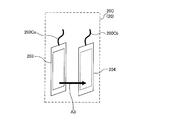
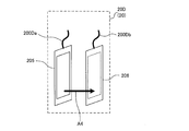
- FIG. 1 to 4 are schematic configuration diagrams showing a schematic configuration example of the liquid level detection device 20 according to the first embodiment of the present invention.
- the liquid level detection device 20 will be described with reference to FIGS. 1 is the liquid level detection device 20A
- the liquid level detection device 20 shown in FIG. 2 is the liquid level detection device 20B
- the liquid level detection device 20 shown in FIG. 3 is the liquid level detection device 20C.
- the liquid level detection device 20 shown in FIG. 4 will be described as a liquid level detection device 20D.
- the liquid level detection device 20A to the liquid level detection device 20D will be described as the liquid level detection device 20 when it is not necessary to particularly distinguish them.
- the liquid level detection device 20 is installed in a container in which a fluid to be detected is stored, and detects a liquid level position of the fluid stored in the container.
- the container include a container constituting an accumulator mounted on a refrigeration cycle apparatus, a container constituting a receiver, a container constituting a compressor, and a container constituting an oil separator. Note that the refrigeration cycle apparatus will be described in Embodiment 2.
- the accumulator is installed on the low pressure side of the refrigerant circuit provided in the refrigeration cycle apparatus.
- the receiver is installed on the medium pressure side or the high pressure side of the refrigerant circuit included in the refrigeration cycle apparatus.
- the compressor is a component of the refrigerant circuit provided in the refrigeration cycle apparatus.
- the oil separator is provided on the discharge side of the compressor provided in the refrigeration cycle apparatus.
- the accumulator and the receiver include a container as a configuration, and the refrigerant circulating in the refrigerant circuit is stored as a liquid refrigerant.
- the liquid refrigerant becomes a detection target of the liquid level detection device 20.
- the compressor is provided with a container as a component, and refrigerating machine oil used in a sliding portion in the container is stored.
- refrigeration oil becomes a detection target of the liquid level detection device 20.
- the oil separator includes a container as a component, and stores the refrigerating machine oil discharged together with the refrigerant.
- refrigeration oil becomes a detection target of the liquid level detection device 20.
- the liquid level detection device 20 includes a heat generation type liquid level detection sensor, a capacitance type liquid level detection sensor, an ultrasonic vibration type liquid level detection sensor, or an optical type liquid level detection sensor.
- the liquid level detection device 20A shown in FIG. 1 is a heat generation type liquid level detection sensor
- the liquid level detection device 20B shown in FIG. 2 is a capacitance type liquid level detection sensor
- the liquid level detection device shown in FIG. 20C is an ultrasonic vibration type liquid level detection sensor
- the liquid level detection apparatus 20D shown in FIG. 4 is an optical liquid level detection sensor.
- the liquid level detection device 20A has two electric wires 200A, two electrodes 202A, and a heating element 201A.
- the left side of the drawing is illustrated as the electric wire 200 ⁇ / b> Aa
- the right side of the drawing is illustrated as the electric wire 200 ⁇ / b> Ab.
- the left side of the drawing is illustrated as an electrode 202Aa
- the right side of the drawing is illustrated as an electrode 202Ab.
- the heating element 201A is disposed between the electrode 202Aa and the electrode 202Ab.
- the electrode 202Aa and the electrode 202Ab are disposed so as to face each other, that is, face each other.
- a current is allowed to flow from the electrode 202Aa to the electrode 202Ab.
- a current flows between the electrode 202Aa and the electrode 202Ab as indicated by an arrow A1 in FIG. That is, in FIG. 1, a current vector (that is, a signal vector) between the electrode 202Aa and the electrode 202Ab is indicated by an arrow A1.
- Liquid level detection using an exothermic sensor comprises a sensor unit that includes two electrodes 202A and a heating element 201A.
- the sensor unit generates heat, and the liquid level is detected by judging gas and liquid based on the temperature response of the sensor unit. It is a method to do.
- the liquid level detection device 20A can be configured by, for example, an NTC sensor, a PTC sensor, or the like that utilizes a change in element resistance (electric resistance) depending on element temperature.
- NTC is an abbreviation for “negative temperature coefficient”
- PTC is an abbreviation for “positive temperature coefficient”.
- the heat generating element 201A generates heat by electric power supplied from the control device side.
- the heating element 201A has a certain relationship between its own heat (temperature) and its own resistance value. For example, when the heating element is used for a PTC sensor, a proportional relationship is established between its own temperature and the resistance value. Further, when the heating element is used for the NTC sensor, an inversely proportional relationship is established between its own temperature and the resistance value.
- the electrode 202A is composed of a plate-like member having a front surface and a back surface.
- the surface of the electrode 202Aa and the surface of the electrode 202Ab are arranged to face each other. That is, the back surface of the electrode 202Aa and the back surface of the electrode 202Ab are directed outward.
- the electrode 202Aa corresponds to the “first plate-like member” of the present invention.
- the electrode 202Ab corresponds to the “second plate-like member” of the present invention.
- the “surface opposite to the surface facing the second plate member” means the back surface of the electrode 202Aa which is the “first plate member”, and “surface facing the second plate member” It means the surface of the electrode 202Aa which is the “first plate member”.
- the heat generating element 201A generates heat by the supplied electric power, and has a size hidden by the electrode 202A. That is, when the liquid level detection device 20A is viewed from one side (back side) of the electrode 202A, the heating element 201A is covered with the electrode 202A and cannot be seen. In other words, the electrode 202A has an area covering the entire heating element 201A.
- the liquid level detection device 20A is connected to a control device (control device 50 shown in FIG. 15 at a later stage) via a wiring (electric wire 200A). Information output from the liquid level detection device 20A is input to the control device.
- a control device control device 50 shown in FIG. 15 at a later stage
- a wiring electric wire 200A
- Information output from the liquid level detection device 20A is input to the control device.
- FIG. 1 the state in which the liquid level detection device 20A is connected to the control device by wire is shown as an example, but the liquid level detection device 20A may be connected to the control device wirelessly.
- the liquid level detection device 20B has two electric wires 200B and two electrodes 202B.
- the left side of the drawing is illustrated as the electric wire 200Ba
- the right side of the drawing is illustrated as the electric wire 200Bb.
- the left side of the drawing is illustrated as an electrode 202Ba
- the right side of the drawing is illustrated as an electrode 202Bb.
- the electrode 202Ba and the electrode 202Bb are arranged to face each other, that is, to face each other.
- a current is allowed to flow from the electrode 202Ba to the electrode 202Bb.
- a current flows between the electrode 202Ba and the electrode 202Bb as indicated by an arrow A2 in FIG. That is, in FIG. 2, a current vector (that is, a signal vector) between the electrode 202Ba and the electrode 202Bb is indicated by an arrow A2.
- the liquid level detection using the capacitance type sensor includes, for example, a sensor unit configured by two electrodes 202B, energizes the sensor unit, and measures gas capacitance by measuring the capacitance of the electrode 202B. This is a method for detecting the liquid level.
- the electrode 202B is composed of a plate-like member having a front surface and a back surface.
- the surface of the electrode 202Ba and the surface of the electrode 202Bb are arranged to face each other. That is, the back surface of the electrode 202Ba and the back surface of the electrode 202Bb are directed outward.
- the electrode 202Ba corresponds to the “first plate-like member” of the present invention.
- the electrode 202Bb corresponds to the “second plate-like member” of the present invention.
- the “surface opposite to the surface facing the second plate member” means the back surface of the electrode 202Ba which is the “first plate member”, and the “surface facing the second plate member” is It means the surface of the electrode 202Ba which is the “first plate member”.
- the liquid level detection device 20B is connected to a control device (a control device 50 shown in FIG. 15 at a later stage) via a wiring (electric wire 200B). Information output from the liquid level detection device 20B is input to the control device.
- a state in which the liquid level detection device 20B is connected to the control device by wire is illustrated as an example, but the liquid level detection device 20B may be connected to the control device wirelessly.
- the liquid level detection device 20 ⁇ / b> C includes two electric wires 200 ⁇ / b> C, a wave transmitter 203, and a wave receiver 204.
- the left side of the drawing is illustrated as the electric wire 200 ⁇ / b> Ca
- the right side of the drawing is illustrated as the electric wire 200 ⁇ / b> Cb.
- the left side of the paper is illustrated as the transmitter 203 and the right side of the paper is illustrated as the receiver 204, but the positional relationship between the transmitter 203 and the receiver 204 may be reversed.
- the transmitter 203 and the receiver 204 are arranged so as to face each other, that is, face each other.
- Ultrasonic waves (or waves and vibrations may be used from the transmitter 203 to the receiver 204, and so on).
- an ultrasonic wave travels between the transmitter 203 and the receiver 204 as indicated by an arrow A3 in FIG. That is, in FIG. 3, the vector (that is, the signal vector) that the ultrasonic wave travels between the transmitter 203 and the receiver 204 is indicated by an arrow A3.
- the liquid level detection using the ultrasonic vibration type sensor includes, for example, a transmitter unit 203 and a receiver unit 204 that form a sensor unit, and the transmitter unit 203 transmits an ultrasonic wave, which is received by the receiver unit 204.
- This is a method of detecting the liquid level by receiving the gas and determining the gas-liquid according to the response at that time.
- the transmitter 203 and the receiver 204 are configured by plate members having a front surface and a back surface. Then, the surface of the transmitter 203 and the surface of the receiver 204 are arranged to face each other. That is, the back surface of the transmitter 203 and the back surface of the receiver 204 are each directed outward.
- the transmitter 203 corresponds to the “first plate member” of the present invention.
- the wave receiver 204 corresponds to the “second plate-like member” of the present invention.
- the “surface opposite to the surface facing the second plate member” means the back surface of the transmitter 203 which is the “first plate member”, and “surface facing the second plate member”. Means the surface of the transmitter 203 which is the “first plate-like member”.
- a reflector may be provided instead of the receiver 204, the ultrasonic wave may be reflected by the reflector, the ultrasonic wave may be received by the transmitter 203, and the gas-liquid may be discriminated.
- the transmitter 203 functions as a transmitter / receiver having not only the function of the transmitter 203 but also the function of the receiver 204.
- the liquid level detection device 20C is connected to a control device (a control device 50 shown in FIG. 15 at a later stage) via a wiring (electric wire 200C). Information output from the liquid level detection device 20C is input to the control device.
- a control device a control device 50 shown in FIG. 15 at a later stage
- a wiring electric wire 200C
- Information output from the liquid level detection device 20C is input to the control device.
- FIG. 3 the state in which the liquid level detection device 20C is connected to the control device by wire is shown as an example, but the liquid level detection device 20C may be connected to the control device wirelessly.
- the liquid level detection device 20 ⁇ / b> D has two electric wires 200 ⁇ / b> D, a light transmitter 205, and a light receiver 206.
- the left side of the drawing is illustrated as the electric wire 200Da
- the right side of the drawing is illustrated as the electric wire 200Db.
- the left side of the paper is illustrated as the light transmitter 205
- the right side of the paper is illustrated as the light receiver 206, but the positional relationship between the light transmitter 205 and the light receiver 206 may be reversed.
- the light transmitter 205 and the light receiver 206 are arranged to face each other, that is, to face each other.
- the light travels from the light transmitter 205 to the light receiver 206. At this time, light travels between the light transmitter 205 and the light receiver 206 as indicated by an arrow A4 in FIG. That is, in FIG. 4, a vector (that is, a signal vector) in which light travels between the light transmitter 205 and the light receiver 206 is indicated by an arrow A4.
- the liquid level detection using the optical sensor is configured by a light transmitter 205 and a light receiver 206 to form a sensor unit, and the light transmitter 205 emits light, which is received by the light receiver 206.
- the liquid level is detected by discriminating gas and liquid according to the light receiving state.
- the light transmitter 205 and the light receiver 206 are configured by plate members having a front surface and a back surface. Then, the surface of the light transmitter 205 and the surface of the light receiver 206 are arranged to face each other. That is, the back surface of the light transmitter 205 and the back surface of the light receiver 206 are directed outward.
- the light transmitter 205 corresponds to the “first plate-like member” of the present invention.
- the light receiver 206 corresponds to the “second plate-like member” of the present invention.
- the “surface opposite to the surface facing the second plate member” means the back surface of the light transmitter 205 which is the “first plate member”, and “surface facing the second plate member”. Means the surface of the light transmitter 205 which is the “first plate-like member”.
- a reflecting plate may be provided instead of the light receiving device 206, the light may be reflected by the reflecting plate, and the light transmitting device 205 may receive the light to discriminate the gas and liquid.
- the light transmitter 205 acts as a light transmitter / receiver having not only the function of the light transmitter 205 but also the function of the light receiver 206.
- the liquid level detection device 20D is connected to a control device (a control device 50 shown in FIG. 15 at a later stage) via a wiring (electric wire 200D).
- the information output from the liquid level detection device 20D is input to the control device.
- FIG. 4 the state in which the liquid level detection device 20D is connected to the control device by wire is shown as an example, but the liquid level detection device 20D may be connected to the control device wirelessly.
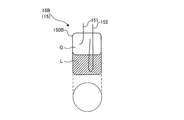
- FIGS. 5 are schematic configuration diagrams showing a schematic configuration example of the liquid reservoir 15 to which the liquid level detection device 20 is attached.
- the liquid reservoir 15 will be described with reference to FIGS. 5 is a liquid storage container 15A
- the liquid storage container 15 shown in FIG. 2 is a liquid storage container 15B
- the liquid storage container 15 shown in FIG. 3 is a liquid storage container 15C
- the container 15 will be described as a liquid storage container 15D.
- the liquid storage container 15 will be described.
- the liquid reservoir 15A is used as a configuration of an accumulator or a receiver, for example.
- the liquid reservoir 15 ⁇ / b> A has a cylindrical appearance, and is arranged so that the cylindrical axis is in the horizontal direction. That is, the liquid reservoir 15A is a horizontal container.
- the liquid storage container 15A can be constituted by a pressure container having a thickness of about 4 to 10 mm, for example.
- FIG. 5 schematically shows a state in which the liquid refrigerant L and the gas refrigerant G are present inside the liquid reservoir 15A.
- the liquid reservoir 15A has a container body 150A that can store the liquid refrigerant L.
- the liquid reservoir 15A has an inlet pipe 151 that is connected to the upper surface of the container body 150A and into which the refrigerant flows. Furthermore, the liquid reservoir 15A has an outlet pipe 152 that is connected to the upper surface portion of the container main body 150A and allows the refrigerant present in the container main body 150A to flow out.
- the liquid reservoir 15A is installed, for example, between an evaporator and a compressor constituting a refrigeration cycle.
- the refrigerant that has passed through the evaporator flows into the container main body 150A via the inlet pipe 151, and in the container main body 150A. It is separated into a liquid refrigerant L and a gas refrigerant G.
- the gas refrigerant G is lighter than the liquid refrigerant, flows above the container main body 150A, flows out of the container main body 150A through the outlet pipe 152, and is sucked into the compressor.
- the liquid refrigerant L is heavier than the gas refrigerant, flows below the container body 150A, and is stored at the bottom of the container body 150A.
- the liquid reservoir 15B is used as a configuration of, for example, an accumulator, a receiver, or an oil separator.
- the liquid storage container 15 ⁇ / b> B has a cylindrical appearance, and is arranged so that the cylindrical axis is in the vertical direction. That is, the liquid reservoir 15B is a vertical container.
- the liquid storage container 15B can be constituted by a pressure container having a thickness of about 4 to 10 mm, for example.
- FIG. 6 schematically shows a state in which the liquid refrigerant L and the gas refrigerant G are present inside the liquid reservoir 15B.
- the liquid storage container 15B is used as an oil separator, the refrigerating machine oil is stored instead of the liquid refrigerant L.
- the liquid reservoir container 15B has a container body 150B that can store the liquid refrigerant L or the refrigerating machine oil.
- the liquid reservoir 15B has an inlet pipe 151 that is connected to the upper surface of the container body 150B and into which the refrigerant flows.
- the liquid storage container 15B has an outlet pipe 152 that is connected to the upper surface portion of the container main body 150B and allows the refrigerant present in the container main body 150B to flow out.
- the liquid reservoir 15B is installed, for example, between an evaporator and a compressor constituting a refrigeration cycle.
- the refrigerant that has passed through the evaporator flows into the container main body 150B via the inlet pipe 151, and is stored in the container main body 150B. It is separated into a liquid refrigerant L and a gas refrigerant G.
- the gas refrigerant G is lighter than the liquid refrigerant, flows above the container body 150B, flows out of the container body 150B through the outlet pipe 152, and is sucked into the compressor.
- the liquid refrigerant L is heavier than the gas refrigerant, flows below the container body 150B, and is stored at the bottom of the container body 150B.
- the liquid reservoir 15B is installed, for example, on the discharge side of the compressor constituting the refrigeration cycle.
- the refrigerant discharged from the compressor flows into the container main body 150B through the inlet pipe 151, and the container main body 150B Swivel inside.
- the gas refrigerant G is lighter than the refrigerating machine oil, flows out from the oil separator through the outlet pipe 152, and flows into the condenser installed on the downstream side of the oil separator.
- the refrigerating machine oil is heavier than the gas refrigerant, dripped below the container body 150B, and stored at the bottom of the container body 150B.
- the liquid reservoir 15C is used as a configuration of a compressor or an oil separator, for example.
- the liquid reservoir 15 ⁇ / b> C has a cylindrical appearance, and is disposed such that the cylindrical axis is in the vertical direction. That is, the liquid reservoir 15C is a vertical container.
- the liquid storage container 15C can be constituted by a pressure container having a thickness of about 4 to 10 mm, for example.
- FIG. 7 schematically shows a state in which the refrigerant R and the refrigerating machine oil O exist inside the liquid reservoir 15C.
- the liquid reservoir container 15C has a container body 150C that can store the refrigerating machine oil O.
- the liquid reservoir 15C has an inlet pipe 151 that is connected to the side surface of the container body 150C and into which the refrigerant flows.
- the liquid storage container 15C has an outlet pipe 152 that is connected to the upper surface of the container main body 150C and allows the refrigerant present in the container main body 150C to flow out.
- the refrigerant R flows into the container body 150C through the inlet pipe 151, and the refrigeration oil O is supplied to the container body 150C. Separated from the refrigerant R. The refrigerant R from which the refrigerating machine oil O has been separated flows out of the container body 150C through the outlet pipe 152. On the other hand, the refrigerating machine oil O flows below the container body 150C and is stored at the bottom of the container body 150C.
- the liquid reservoir 15D is used as a configuration of a compressor or an oil separator, for example.
- the liquid reservoir 15 ⁇ / b> D has a cylindrical appearance and is arranged so that the cylindrical axis is in the vertical direction. That is, the liquid reservoir 15D is a vertical container.
- the liquid storage container 15D can be constituted by a pressure container having a thickness of about 4 to 10 mm, for example.
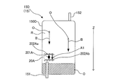
- FIG. 8 schematically shows a state where the refrigerant R and the refrigerating machine oil O are present in the liquid reservoir 15D.
- the liquid reservoir container 15D has a container body 150D that can store the refrigerating machine oil O.
- the liquid reservoir 15D has an inlet pipe 151 that is connected to the bottom surface of the container body 150D and into which the refrigerant flows.
- the liquid storage container 15D has an outlet pipe 152 that is connected to the upper surface of the container main body 150D and allows the refrigerant present in the container main body 150D to flow out.
- the refrigerant R flows into the container main body 150D through the inlet pipe 151, and the refrigerating machine oil O is supplied to the container main body 150D. Separated from the refrigerant R. The refrigerant R from which the refrigerating machine oil O is separated flows out of the container main body 150D through the outlet pipe 152. On the other hand, the refrigerating machine oil O flows below the container body 150D and is stored at the bottom of the container body 150D.
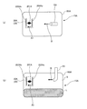
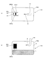
- FIG. 9 is a schematic diagram for explaining an example of a method of installing the liquid level detection device 20 in the horizontal container.
- FIG. 10 is a schematic diagram for explaining an example of a method of installing a liquid level detection device as a comparative example in a horizontal container.
- FIG. 9A is a diagram schematically showing a state in which the liquid storage container 15A is viewed from the bottom surface side
- FIG. 9B is a diagram schematically showing a state in which the liquid storage container 15A is viewed from the side surface. It is.
- FIG. 10A is a diagram schematically showing a state in which the reservoir 15A is viewed from the bottom side
- FIG. 10B is a diagram schematically showing a state in which the reservoir 15A is viewed from the side. It is.
- FIGS. 9 and 10 show an example in which the liquid level detection device 20A is installed in the liquid reservoir 15A which is the horizontal container shown in FIG. In FIGS. 9 and 10, the electric wire 200A and the outlet pipe 152 are not shown.
- the liquid level detection device 20A is installed inside the container body 150A of the liquid reservoir 15A.
- the liquid level detection device 20A is attached to, for example, a lower limit position and an upper limit position of a fluid (for example, a liquid refrigerant) stored in the container main body 150A.
- a fluid for example, a liquid refrigerant
- the installation number and installation position of the liquid level detection device 20A are not particularly limited, and may be appropriately determined depending on the application, volume, type of fluid to be stored, and the like of the liquid storage container 15 to be installed.
- the liquid reservoir 15A in which the liquid level detection device 20A shown in FIG. 9 is installed is an accumulator or receiver container.
- the refrigerant circulating in the refrigerant circuit provided in the refrigeration cycle apparatus flows into the container main body 150A, and the liquid refrigerant L is stored in the container main body 150A.
- the electrode 202Aa and the electrode 202Ab are arranged to face each other, and the electrode 202Aa is arranged so that the back surface of the electrode 202Aa is orthogonal to the fluid flow direction around the installation position of the liquid level detection device 20A.
- the liquid level detection device 20A includes the signal vector (arrow A1) flowing between the electrodes 202A and the fluid flowing into the liquid reservoir 15A and flowing around the liquid level detection device 20A.
- the streamline vector (arrow B) is installed in parallel.
- the back surface of the electrode 202Aa does not need to be strictly orthogonal to the fluid flow direction, and includes a slight deviation (range of ⁇ 10 °) (the liquid level detection device 20C to the liquid level detection device). The same applies to 20D).
- the liquid level detection device 20A by installing the liquid level detection device 20A, it is possible to prevent the liquid droplets flowing into the container body 150A from the inlet pipe 151 from being disturbed by the electrode 202A and coming into contact with the heating element 201A. That is, the electrode 202A has a function as a shielding part. Therefore, in the container main body 150A, the fluid flowing around the liquid level detection device 20A collides with the electrode 202A, the fluid flow is cut off, and does not reach the heating element 201A.
- FIG. 10 shows a state in which the electrodes 202Aa and 202Ab arranged opposite to each other are arranged in parallel with the fluid flow around the installation location of the liquid level detection device 20A as a comparative example. That is, in the installation example shown in FIG. 10, the liquid level detection device 20A includes a signal vector (arrow A1) that flows between the electrodes 202A and the fluid that flows into the liquid reservoir 15A and flows around the liquid level detection device 20A.
- the streamline vector (arrow B) is installed so as to be orthogonal.
- the liquid level detection device 20A when the liquid level detection device 20A is installed, the liquid droplets flowing into the container main body 150A from the inlet pipe 151 contact the heating element 201A without being obstructed by the electrode 202A. Therefore, the fluid reaches the heat generating element 201A. In such a case, the temperature response of the heat generating element 201A may change due to the influence of the droplet, and the liquid level detection device 20A may make an erroneous determination.
- the liquid level detection device 20A determines that the gas part is the liquid part because the droplet does not contact the heating element 201A. There is no false detection.
- the liquid level detection device 20A is installed as shown in FIG. 10, there is a high possibility that the droplet contacts the heating element 201A, and the liquid level detection device 20A is a gas part, even though the liquid level detection device 20A is a gas part. Depending on the purpose, it will be determined as a liquid part, that is, erroneous detection will occur.
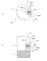
- FIG. 11 is a schematic diagram for explaining an example of a method of installing the liquid level detection device 20 in the vertical container.
- FIG. 12 is a schematic diagram for explaining an example of a method of installing a liquid level detection device as a comparative example in a vertical container.
- FIG. 11A is a diagram schematically showing a state in which the liquid storage container 15B is viewed from the bottom surface side
- FIG. 11B is a diagram schematically showing a state in which the liquid storage container 15B is viewed from the side surface.
- FIG. 12A is a diagram schematically showing a state in which the reservoir 15B is viewed from the bottom surface side
- FIG. 12B is a diagram schematically showing a state in which the reservoir 15B is viewed from the side. It is.
- FIGS. 11 and 12 show an example in which the liquid level detection device 20A is installed in the liquid reservoir 15B which is the vertical container shown in FIG. In FIGS. 11 and 12, the electric wire 200A and the outlet pipe 152 are not shown.
- the liquid level detection device 20A is installed inside the container body 150B of the liquid reservoir 15B.
- the liquid level detection device 20A is attached to, for example, a lower limit position and an upper limit position of a fluid (for example, liquid refrigerant) stored in the container main body 150B.
- a fluid for example, liquid refrigerant
- the installation number and installation position of the liquid level detection device 20A are not particularly limited, and may be appropriately determined depending on the application, volume, type of fluid to be stored, and the like of the liquid storage container 15 to be installed.
- the liquid reservoir 15B in which the liquid level detection device 20A shown in FIG. 11 is installed is an accumulator, receiver, or oil separator container.
- the refrigerant circulating in the refrigerant circuit included in the refrigeration cycle apparatus flows into the container main body 150B, and the liquid refrigerant L is stored in the container main body 150B. Since it is important to grasp the amount of refrigerant for efficient operation of the refrigeration cycle apparatus, the amount of refrigerant is grasped from the amount of liquid refrigerant L stored using the liquid level detection device 20.
- the refrigeration oil O flows into the container body 150B together with the refrigerant, is separated from the refrigerant R, and is stored in the bottom of the container body 150C. That is, the refrigerating machine oil O is discharged to the outside of the compressor together with the refrigerant R.
- the refrigerating machine oil O can be returned to the compressor, and the refrigerating machine oil O can be prevented from being exhausted from the compressor.
- the operation efficiency of the refrigeration cycle apparatus is reduced. Therefore, by detecting the liquid level of the refrigeration oil O using the liquid level detection device 20, the oil return timing to the compressor can be optimized, and the operating efficiency of the refrigeration cycle apparatus can be prevented from being lowered.
- the electrode 202Aa and the electrode 202Ab are arranged to face each other, and the electrode 202Aa is arranged so that its back surface is orthogonal to the flow direction of the fluid around the installation position of the liquid level detection device 20A. ing.
- the fluid flowing from the inlet pipe 151 into the container main body 150B of the liquid storage container 15B flows while swirling along the wall surface of the container main body 150A. Therefore, in the installation example shown in FIG. 11, the liquid level detection device 20A includes a signal vector (arrow A1) that flows between the electrodes 202A and a fluid that flows into the liquid reservoir 15A and flows around the liquid level detection device 20A.
- the streamline vector (arrow B) is installed in parallel.
- the liquid level detection device 20A by installing the liquid level detection device 20A, it is possible to prevent the liquid droplets flowing into the container body 150B from the inlet pipe 151 from being disturbed by the electrode 202A and coming into contact with the heating element 201A. That is, the electrode 202A has a function as a shielding part. Therefore, in the container main body 150B, the fluid flowing around the liquid level detection device 20A collides with the electrode 202A, the fluid flow is cut off, and does not reach the heating element 201A.
- FIG. 12 a state in which the electrodes 202Aa and 202Ab arranged opposite to each other are arranged in parallel with the fluid flow around the installation location of the liquid level detection device 20A is shown as a comparative example. That is, in the installation example shown in FIG. 12, the liquid level detection device 20A includes a signal vector (arrow A1) that flows between the electrodes 202A and a fluid that flows into the liquid reservoir 15B and flows around the liquid level detection device 20A.
- the streamline vector (arrow B) is installed so as to be orthogonal.
- the liquid level detection device 20A when the liquid level detection device 20A is installed, the liquid droplets flowing into the container main body 150B from the inlet pipe 151 are not disturbed by the electrode 202A and come into contact with the heating element 201A. Therefore, the fluid reaches the heat generating element 201A. In such a case, the temperature response of the heat generating element 201A may change due to the influence of the droplet, and the liquid level detection device 20A may make an erroneous determination.
- the liquid level detection device 20A determines that the gas part is the liquid part because the droplet does not contact the heating element 201A. There is no false detection.
- the liquid level detection device 20A is installed as shown in FIG. 12, there is a high possibility that the droplet contacts the heating element 201A, and the liquid level detection device 20A is a gas part, even though the liquid level detection device 20A is a gas part. Depending on the purpose, it will be determined as a liquid part, that is, erroneous detection will occur.
- a method (part 2) of installing the liquid level detection device 20 in the vertical container will be described taking the liquid level detection device 20A as an example.
- 13 and 14 are schematic views for explaining an example of a method for installing the liquid level detection device 20 in the vertical container. Arrows Z shown in FIGS. 13 and 14 indicate the direction of gravity.
- FIG. 13 shows an example in which the liquid level detection device 20A is installed in the liquid reservoir 15C which is the vertical container shown in FIG.
- FIG. 14 shows an example in which the liquid level detection device 20A is installed in the liquid reservoir 15D which is the vertical container shown in FIG.
- the electric wire 200A is not shown. 13 and 14 schematically show a state where the refrigerant R and the refrigerating machine oil O are present inside the container main body 150C and the container main body 150D.
- the liquid level detection device 20A is installed inside the container body 150C of the liquid reservoir 15C.
- the liquid level detection device 20A is attached to a lower limit position and an upper limit position of a fluid (for example, refrigerating machine oil or the like) stored in the container body 150C, for example.
- a fluid for example, refrigerating machine oil or the like
- the installation number and installation position of the liquid level detection device 20A are not particularly limited, and may be appropriately determined depending on the application, volume, type of fluid to be stored, and the like of the liquid storage container 15 to be installed.
- the liquid reservoir 15C in which the liquid level detection device 20A shown in FIG. 13 is installed is assumed to be a container used as a compressor or an oil separator.
- the refrigeration oil O flows into the container main body 150C together with the refrigerant, is separated from the refrigerant R, and is stored in the bottom of the container main body 150C (oil reservoir 115 shown in FIG. 16). Is done.
- the refrigerating machine oil O is supplied to sliding parts (bearing part, thrust bearing part, etc.) of a compressing part (compressing part 112 shown in FIG. 16) that compresses the refrigerant, lubricates the sliding part, and then the bottom part of the container body 150C.
- the refrigerator oil O is discharged together with the refrigerant R to the outside of the compressor.
- the sliding portion of the compression portion cannot be sufficiently lubricated. Therefore, by using the liquid level detection device 20 and detecting the liquid level of the refrigerating machine oil O, the amount of refrigerating machine oil O remaining in the compressor can be grasped.
- liquid reservoir 15C is used as an oil separator.
- the electrode 202Aa and the electrode 202Ab are arranged to face each other, and the electrode 202Aa is orthogonal to the flow direction of the refrigerating machine oil O dripping down from above the container body 150C. Is arranged.
- the refrigerating machine oil O used in the sliding part of the compressor or the refrigerating machine oil O separated from the refrigerant R drops from the upper side of the container main body 150C downward according to the gravity. Therefore, in the installation example shown in FIG. 13, the liquid level detection device 20A has a signal vector (arrow A1) that flows between the electrodes 202A and a streamline vector (arrow B) of the fluid that drops in the container body 150C. It is installed to be parallel.
- the liquid level detection device 20A by installing the liquid level detection device 20A, it is possible to prevent the liquid droplets dropped inside the container main body 150C from being disturbed by the electrode 202A and coming into contact with the heating element 201A. That is, the electrode 202A has a function as a shielding part. Therefore, in the container main body 150C, the fluid dripping toward the liquid level detection device 20A collides with the electrode 202A, the flow of the fluid is interrupted, and does not reach the heating element 201A.
- the liquid level detection device 20A determines that the gas part is the liquid part. There is no false detection.
- the liquid level detection device 20A is installed inside the container body 150D of the liquid reservoir container 15D.
- the liquid level detection device 20A is attached to, for example, a lower limit position and an upper limit position of a fluid (for example, refrigeration oil) stored in the container body 150D.
- a fluid for example, refrigeration oil
- the installation number and installation position of the liquid level detection device 20A are not particularly limited, and may be appropriately determined depending on the application, volume, type of fluid to be stored, and the like of the liquid storage container 15 to be installed.
- the liquid reservoir 15D in which the liquid level detection device 20A shown in FIG. 14 is installed is assumed to be a container used as an oil separator.
- the liquid storage container 15D may be used as a configuration of an accumulator or refrigerator oil. In this case, the detection target is not the refrigerator oil O but the liquid refrigerant.
- liquid reservoir 15D is used as an oil separator
- the electrode 202Aa and the electrode 202Ab are arranged to face each other, and the electrode 202Aa is orthogonal to the flow direction of the refrigerating machine oil O dripping from the upper side of the container main body 150D downward. Is arranged.
- the refrigerating machine oil O separated from the refrigerant R drops from the upper side to the lower side of the container body 150C according to gravity. Therefore, in the installation example shown in FIG. 14, the liquid level detection device 20A has a signal vector (arrow A1) that flows between the electrodes 202A and a streamline vector (arrow B) of the fluid that drops in the container body 150D. It is installed to be parallel.
- the liquid level detection device 20A by installing the liquid level detection device 20A, it is possible to prevent the liquid droplets dropped inside the container body 150D from being disturbed by the electrode 202A and coming into contact with the heating element 201A. That is, the electrode 202A has a function as a shielding part. Therefore, in the container main body 150D, the fluid dropped toward the liquid level detection device 20A collides with the electrode 202A, the fluid flow is cut off, and does not reach the heating element 201A.
- the liquid level detection device 20A determines that the gas part is the liquid part because the droplet does not contact the heating element 201A. There is no false detection.
- liquid level detection device 20A is installed in the liquid reservoir 15
- the first plate-like member (the electrode 202Aa, the electrode 202Ba, the wave transmitter 203, and the light transmitter 205) and the second plate disposed to face the first plate-like member.
- a plate member (electrode 202Ab, electrode 202Bb, wave receiver 204 (or reflector), light receiver 206 (or reflector)), and the back surface of the first plate member is in the liquid reservoir 15 Since the first plate-like member also serves as a shielding portion even when the liquid droplets are scattered, the first plate-like member also serves as a shielding portion. Therefore, it is possible to suppress erroneous determination.
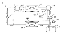
- FIG. FIG. 15 is a schematic configuration diagram showing an example of a refrigerant circuit configuration of a refrigeration cycle apparatus (hereinafter referred to as refrigeration cycle apparatus 1) according to Embodiment 2 of the present invention.
- the refrigerant circuit configuration and operation of the refrigeration cycle apparatus 1 will be described based on FIG.
- differences from the first embodiment will be mainly described, and the same parts as those in the first embodiment will be denoted by the same reference numerals and description thereof will be omitted.
- the refrigeration cycle apparatus 1 performs vapor compression refrigeration cycle operation, and the liquid level detection device 20 according to the first embodiment is configured to store fluid (for example, the compressor 11, the oil separator 16, the accumulator). 18, at least one of the receivers 35).
- fluid for example, the compressor 11, the oil separator 16, the accumulator. 18, at least one of the receivers 35).
- the refrigeration cycle apparatus 1 includes a compressor 11, a condenser 12, an expansion device 13, an evaporator 14, an accumulator 18, an oil separator 16, a liquid level detection device 20, and a control device 50. ing.
- the compressor 11, the condenser 12, the expansion device 13, and the evaporator 14 are connected by a refrigerant pipe 30 to form a refrigerant circuit.
- the oil separator 16 is provided on the refrigerant discharge side of the compressor 11, and the accumulator 18 is provided on the refrigerant suction side of the compressor 11.
- the compressor 11 is used for conveying a refrigerant.
- the compressor 11 has a function of compressing and discharging a gas refrigerant at a high temperature and a high pressure.
- the refrigerant suction side is connected to the accumulator 18, and the refrigerant discharge side is connected to the condenser 12.
- the condenser 12 is connected to the refrigerant discharge side of the compressor 11 via an oil separator 16.
- the compressor 11 can be comprised with an inverter compressor etc., for example.
- a rotary compressor, a scroll compressor, a screw compressor, a reciprocating compressor, or the like can be employed as the compressor 11.
- the oil separator 16 separates the refrigerating machine oil discharged together with the refrigerant from the compressor 11 and returns it to the suction side of the compressor 11 via the bypass valve 17.
- the oil separator 16 is a device that separates the discharge gas discharged from the compressor 11 and the refrigerating machine oil and returns only the refrigerating machine oil to the suction unit of the compressor 11.
- the lower side of the oil separator 16 and the suction side of the compressor 11 are connected by a bypass pipe 31.
- the bypass valve 17 is installed in the bypass pipe 31.
- the bypass valve 17 opens or closes the bypass pipe 31 to block or allow the refrigerant flow.
- the bypass valve 17 can be configured by, for example, an electromagnetic valve that can open and close the bypass pipe 31.
- the condenser 12 (heat radiator) condenses the refrigerant discharged from the compressor 11 into a high-pressure liquid refrigerant.
- the condenser 12 has an upstream side connected to the compressor 11 and a downstream side connected to the expansion device 13.
- the condenser 12 can be composed of, for example, a fin-and-tube heat exchanger or the like.
- the condenser 12 is provided with a blower 12 ⁇ / b> A that supplies air as a heat exchange medium to the condenser 12.
- the expansion device 13 expands the refrigerant that has passed through the condenser 12 to reduce the pressure.
- the expansion device 13 may be configured by an electric expansion valve or the like that can adjust the opening and adjust the flow rate of the refrigerant, for example.
- the expansion device 13 has an upstream side connected to the condenser 12 and a downstream side connected to the evaporator 14.
- the evaporator 14 evaporates the refrigerant depressurized by the expansion device 13 to form a gas refrigerant.
- the evaporator 14 has an upstream side connected to the expansion device 13 and a downstream side connected to the accumulator 18.
- the evaporator 14 can be configured by, for example, a fin-and-tube heat exchanger or the like.
- the evaporator 14 is provided with a blower 14 ⁇ / b> A that supplies air as a heat exchange medium to the evaporator 14.
- the accumulator 18 has a function of storing liquid refrigerant or the like.
- the accumulator 18 has an upstream side connected to the evaporator 14 and a downstream side connected to the suction side of the compressor 11.
- the receiver 35 has a function of storing a liquid refrigerant or the like, like the accumulator.
- the receiver 35 has an upstream side connected to the condenser 12 and a downstream side connected to the expansion device 13.
- the liquid level position of the liquid refrigerant stored in the liquid storage container 15 and the oil level position of the refrigerating machine oil stored in the container are detected.
- the liquid level detection device 20 is installed in at least one of the accumulator 18, the compressor 11, and the oil separator 16, for example. That is, the accumulator 18, the compressor 11, and the oil separator 16 have the function as the liquid reservoir 15 described in the first embodiment.
- FIG. 15 shows an example in which the liquid level detection device 20 is installed in all of the accumulator 18, the compressor 11, and the oil separator 16, but it may be installed in at least one of them.
- the control device 50 calculates the amount of liquid fluid stored in the container installed based on the detection result of the liquid level detection device 20.
- the control device 50 includes a power supply circuit unit that supplies voltage (electric power) to the liquid level detection device 20, an arithmetic circuit unit that calculates the temperature of the heating element 201A of the liquid level detection device 20, and the heating element 201A. And a storage unit that stores a predetermined table indicating the relationship between the resistance value and the temperature.
- the resistance value of the heat generating element 201A increases as the temperature of the heat generating element 201A increases.
- the temperature of the heating element 201A is lower than when the heating element 201A is in contact with the gas refrigerant.
- the resistance value of the heating element 201A also decreases correspondingly.
- the resistance value is higher than that in the case of touching the liquid refrigerant.
- the resistance value of the heating element 201A differs depending on whether the heating element 201A of the liquid level detection device 20 is in contact with the liquid refrigerant or the gas refrigerant. Therefore, the control device 50 detects the liquid level based on such information sent from the liquid level detection device 20.
- control device 50 calculates the resistance value of each of the heating elements 201A from the voltage value and current value supplied to each of the heating elements 201A. In addition, the control device 50 calculates each temperature using a predetermined table from each resistance value of the heating element 201A. Then, the control device 50 determines where the liquid level of the liquid reservoir 15A is based on the temperature of the heat generating element 201A.
- the control device 50 can determine whether or not the liquid refrigerant in the accumulator 18 overflows based on the detection result of the liquid level detection device 20. Further, the control device 50 can determine whether or not the refrigerant filled in the refrigerant circuit of the refrigeration cycle apparatus 1 is leaking. Furthermore, the control device 50 can calculate the charging amount of the refrigerant when charging the refrigerant after the refrigeration cycle apparatus 1 is installed.
- each actuator (drive component) is connected to the control device 50, and the control device 50 controls the operation of each actuator.
- the actuator include a compressor 11, a throttle device 13, a bypass valve 17, a blower 12A, a blower 14A, and the like.
- the control device 50 has a function of controlling the operation of each actuator based on detection values from various other sensors (not shown) in addition to the function of calculating the amount of liquid fluid.
- the control device 50 can be configured by hardware such as a circuit device that realizes the function, or can be configured by an arithmetic device such as a microcomputer or a CPU and software executed thereon.
- the blower 12A is mounted on the outdoor unit together with the condenser 12
- the blower 14A is mounted on the indoor unit together with the evaporator 14.
- the blower 12 ⁇ / b> A is used to supply heat to the condenser 12 and promote heat exchange between the refrigerant flowing through the condenser 12 and air.
- the blower 14 ⁇ / b> A is used to supply heat to the evaporator 14 and promote heat exchange between the refrigerant flowing through the evaporator 14 and the air.
- the condenser 12 is configured to exchange heat between water or brine and the refrigerant
- a pump for conveying water or brine or the like to the condenser 12 is installed instead of the blower 12A.
- the evaporator 14 is configured to exchange heat between water, brine, or the like and the refrigerant
- a pump that conveys water, brine, or the like to the evaporator 14 is installed instead of the blower 14A.
- the refrigeration cycle apparatus 1 is used as a hot water supply apparatus, an air-conditioning hot water supply combined apparatus, a refrigeration apparatus, etc., in addition to an air conditioner.
- the receiver 35 when the receiver 35 is provided, the receiver 35 may be provided on the downstream side of the condenser 12 as shown in FIG.
- the liquid level detection device 20 may be installed also in the receiver 35.
- the receiver 35 also has a function as the liquid reservoir 15 described in the first embodiment.
- the receiver 35 may be provided together with the accumulator 18, or only one of them may be provided.
- FIG. 16 is a schematic configuration diagram schematically showing the configuration of the compressor 11 that is one component of the refrigeration cycle apparatus 1. Based on FIG. 16, the installation location of the liquid level detection apparatus 20 in the compressor 11 is demonstrated. The liquid level detection by the liquid level detection device 20 is as described in the first embodiment.
- the compressor 11 has a suction part 110, a discharge part 111, a compression part 112, a motor part 113, a shaft / oil pump part 114, and an oil sump part 115.
- the suction part 110 corresponds to the inlet pipe 151 described in the first embodiment
- the discharge part 111 corresponds to the outlet pipe 152 described in the first embodiment.
- the gas refrigerant is sucked into the compressor 11 from the suction part 110.
- the gas refrigerant sucked into the compressor 11 is compressed by the compression unit 112 by the rotational force of the motor unit 113.
- the high-pressure and high-temperature gas refrigerant compressed by the compression unit 112 is discharged from the discharge unit 111.
- the refrigerating machine oil stored in the oil sump 115 is supplied to the compression part 112 through the shaft / oil pump part 114 in order to reduce the friction of the sliding part of the compression part 112. ing.
- the motor unit 113 will be filled with refrigerating machine oil and the rotational efficiency will be reduced.
- the amount of the refrigerating machine oil is too small, the compression unit 112 refrigerating machine oil cannot be supplied, and the friction increases, which may cause a failure. For this reason, it is desirable to control the refrigerating machine oil to an appropriate amount. Therefore, in the refrigeration cycle apparatus 1, the liquid level detection device 20 is installed in the oil reservoir 115 of the compressor 11 in order to grasp the appropriate amount of refrigeration oil. For example, as shown in FIG. 16, the two liquid level detection devices 20 may be installed at the lower limit position and the upper limit position of the oil sump 115.
- the installation location of the liquid level detection device 20 in the accumulator 18 is not particularly limited, for example, two liquid level detection devices 20 may be installed at the lower limit position and the upper limit position of the accumulator 18.
- three or more liquid level detection devices 20 may be arranged side by side in the vertical direction.
- the first plate member and the second plate member constituting the liquid level detection device 20 are extended in the vertical direction to detect a plurality of liquid levels. You may make it do.
- high-temperature and high-pressure gaseous refrigerant is discharged from the compressor 11.
- the high-temperature and high-pressure gas refrigerant (single phase) discharged from the compressor 11 flows into the condenser 12 through the oil separator 16.
- the condenser 12 heat exchange is performed between the flowing high-temperature and high-pressure gas refrigerant and the air supplied by the blower 12A, and the high-temperature and high-pressure gas refrigerant is condensed to a high-pressure liquid refrigerant (single phase). become.
- the high-pressure liquid refrigerant sent out from the condenser 12 is converted into a two-phase refrigerant consisting of a low-pressure gas refrigerant and a liquid refrigerant by the expansion device 13.
- the two-phase refrigerant flows into the evaporator 14.
- heat exchange is performed between the refrigerant flowing in the two-phase state and the air supplied by the blower 14 ⁇ / b> A, and the liquid refrigerant evaporates out of the refrigerant in the two-phase state, and the low-pressure gas refrigerant ( Single phase).
- the low-pressure gas refrigerant sent out from the evaporator 14 flows into the compressor 11 via the accumulator 18, is compressed to become a high-temperature high-pressure gas refrigerant, and is discharged from the compressor 11 again. Thereafter, this cycle is repeated.
- the case where the exothermic liquid level detection sensor (the liquid level detection device 20A according to the first embodiment) is used as the liquid level detection device 20 has been described as an example.
- Liquid level detection sensor liquid level detection device 20B according to the first embodiment
- ultrasonic vibration type liquid level detection sensor liquid level detection device 20C according to the first embodiment
- optical liquid level detection sensor Even when the liquid level detection device 20D according to Embodiment 1 is used, the liquid level can be detected in the same manner. Even in these liquid level detection devices, the measurement value in the sensor unit differs depending on whether there is liquid or gas in the sensor unit (first plate member and second plate member). The gas-liquid can be judged by the value.
- the control device 50 calculates the temperature from the resistance value.
- the present invention is not limited to this.
- the control apparatus 50 may compare the resistance value of the heat generating element 201A without converting it into temperature.
- the heating element 201A has been described as having both a function as a heat generating element and a function as an element whose resistance changes.
- the present invention is not limited to this, and both functions are separated. You may make it bear in the composition of.
- the liquid level detection device 20A can be configured by providing, in place of the heating element 201A, a heating body and a temperature sensor attached to the heating body separately from the heating body.
- a thermistor can be used as the temperature sensor.
- a resistor etc. are employable, for example. And self can be heated by supplying with electricity to a resistor.
- the refrigeration cycle apparatus 1 includes the liquid level detection device 20 according to Embodiment 1, the first plate member serves as a blocking plate, and the fluid does not directly contact the heating element 201A. It can suppress that detection accuracy falls.
- the first plate member serves as a blocking plate, and the fluid is between the first plate member and the second plate member. Since the liquid does not flow, the liquid level detection accuracy is not reduced.
- the sensor unit of the liquid level detection device 20 has been described as an example in which the sensor unit is a single unit (a pair of the first plate member and the second plate member), but the configuration is not limited thereto. For example, a plurality of sensor units may be provided.
- the liquid level detection device 20 can also be used as an overflow detection technology sensor that detects that the liquid refrigerant overflows from the accumulator 18, and can suppress the return of the liquid refrigerant to the compressor 11. If it does in this way, failure of compressor 11 can be controlled and the reliability of compressor 11 can be raised.
- the refrigeration cycle apparatus 1 can accurately grasp the amount of liquid in the accumulator 18 when the refrigerant is charged after the refrigerant circuit is installed in a building or the like, the refrigerant circuit is not overfilled with the refrigerant.
- refrigerant leakage can be detected and dealt with early, and global warming can be suppressed. Can do. Further, it is possible to detect refrigerant leakage such as combustible refrigerant at an early stage, and to prevent occurrence of serious accidents such as combustion and explosion, for example.
- liquid level detection device 20 makes a false detection, there are the following inconveniences, and the refrigeration cycle device 1 may not be able to operate normally, and it may lead to equipment failure.
- the liquid level detection device 20 installed in the accumulator 18 erroneously detects the gas part as the liquid part
- the liquid refrigerant stored in the accumulator 18 is stored in the condenser 12 on the high pressure side.
- the degree of superheat at the outlet is increased, and the superheated gasified refrigerant flows into the accumulator 18.
- more liquid refrigerant than necessary is collected in the condenser 12, so that the high pressure rises, the high pressure becomes abnormal, and normal operation cannot be performed.
- the liquid level detection device 20 that detects the oil level of the refrigerating machine oil of the compressor 11 erroneously detects the gas part as the liquid part, the compressor 11 is in a state where there is not much refrigerating machine oil in the compressor 11. Control to reduce internal refrigeration oil will be performed. Therefore, it becomes impossible to secure the refrigerating machine oil necessary for the lubrication of the compressor 11, and the sliding portion of the compressor 11 is burned, causing a compressor failure.
- the receiver 35 may be installed on the high-pressure side of the refrigerant circuit of the refrigeration cycle apparatus 1, and the liquid level detection device 20 may be installed on the receiver 35. Further, when a plurality of liquid level detection devices 20 are installed, all of them may be the same type of liquid level detection device 20, all types of liquid level detection devices 20 may be combined, or some may be the same type.
- the liquid level detection device 20 may be used. That is, when the lower limit liquid level of the liquid refrigerant stored in the accumulator 18 is detected, the liquid level detection device 20D according to the first embodiment is used. You may utilize the liquid level detection apparatus 20B which concerns on the form 1.
- the liquid level detection result by sending the liquid level detection result to the management center or the like, the liquid level can be detected remotely at any time. Therefore, it is possible to cope with sudden refrigerant leakage immediately before an abnormality such as damage to the equipment or a decrease in capability occurs, and it is possible to suppress the progression of refrigerant leakage as much as possible. Thereby, the reliability of the refrigeration cycle apparatus 1 can be improved, and deterioration of the environmental state due to the outflow of refrigerant can be prevented as much as possible.
- Refrigeration cycle device 11 compressor, 12 condenser, 12A blower, 13 throttling device, 14 evaporator, 14A blower, 15 liquid reservoir, 15A liquid reservoir, 15B liquid reservoir, 15C liquid reservoir, 15D liquid reservoir Container, 16 Oil separator, 17 Bypass valve, 18 Accumulator, 20 Liquid level detection device, 20A Liquid level detection device, 20B Liquid level detection device, 20C Liquid level detection device, 20D Liquid level detection device, 30 Refrigerant piping, 31 Bypass piping , 35 receiver, 50 control device, 110 suction section, 111 discharge section, 112 compression section, 113 motor section, 114 oil pump section, 115 oil sump section, 150A container body, 150B container body, 150C container body, 150D container body, 151 Inlet pipe, 152 Outlet pipe 200A electric wire, 200Aa electric wire, 200Ab electric wire, 200B electric wire, 200Ba electric wire, 200Bb electric wire, 200C electric wire, 200Ca electric wire, 200C
Landscapes
- Physics & Mathematics (AREA)
- Engineering & Computer Science (AREA)
- Thermal Sciences (AREA)
- Fluid Mechanics (AREA)
- General Physics & Mathematics (AREA)
- Power Engineering (AREA)
- Electromagnetism (AREA)
- Mechanical Engineering (AREA)
- General Engineering & Computer Science (AREA)
- Chemical & Material Sciences (AREA)
- Analytical Chemistry (AREA)
- Acoustics & Sound (AREA)
- Measurement Of Levels Of Liquids Or Fluent Solid Materials (AREA)
Abstract
L'invention concerne un capteur de niveau de liquide disposé à l'intérieur d'un récipient de manière à détecter le niveau d'un fluide retenu dans le récipient, et comprend un premier élément en forme de plaque formé en une forme de plaque et un second élément en forme de plaque formé en une forme de plaque et disposé de façon à faire face au premier élément en forme de plaque. Le premier élément en forme de plaque est disposé de manière qu'une surface se trouvant sur le côté opposé de la surface faisant face au second élément en forme de plaque soit perpendiculaire à la direction d'écoulement du fluide autour du premier élément en forme de plaque à l'intérieur du récipient.
Priority Applications (5)
| Application Number | Priority Date | Filing Date | Title |
|---|---|---|---|
| PCT/JP2016/080900 WO2018073902A1 (fr) | 2016-10-19 | 2016-10-19 | Capteur de niveau de liquide et système de cycle de réfrigération |
| US16/318,436 US11493248B2 (en) | 2016-10-19 | 2016-10-19 | Liquid level detection device and refrigeration cycle apparatus |
| CN201680089479.8A CN109863373B (zh) | 2016-10-19 | 2016-10-19 | 制冷循环装置 |
| EP16919274.7A EP3531085B1 (fr) | 2016-10-19 | 2016-10-19 | Appareil à cycle de réfrigération |
| JP2018546078A JP6925357B2 (ja) | 2016-10-19 | 2016-10-19 | 冷凍サイクル装置 |
Applications Claiming Priority (1)
| Application Number | Priority Date | Filing Date | Title |
|---|---|---|---|
| PCT/JP2016/080900 WO2018073902A1 (fr) | 2016-10-19 | 2016-10-19 | Capteur de niveau de liquide et système de cycle de réfrigération |
Publications (1)
| Publication Number | Publication Date |
|---|---|
| WO2018073902A1 true WO2018073902A1 (fr) | 2018-04-26 |
Family
ID=62019315
Family Applications (1)
| Application Number | Title | Priority Date | Filing Date |
|---|---|---|---|
| PCT/JP2016/080900 Ceased WO2018073902A1 (fr) | 2016-10-19 | 2016-10-19 | Capteur de niveau de liquide et système de cycle de réfrigération |
Country Status (5)
| Country | Link |
|---|---|
| US (1) | US11493248B2 (fr) |
| EP (1) | EP3531085B1 (fr) |
| JP (1) | JP6925357B2 (fr) |
| CN (1) | CN109863373B (fr) |
| WO (1) | WO2018073902A1 (fr) |
Families Citing this family (3)
| Publication number | Priority date | Publication date | Assignee | Title |
|---|---|---|---|---|
| US11085683B2 (en) * | 2018-06-22 | 2021-08-10 | Emerson Climate Technologies Retail Solutions, Inc. | Systems and methods for optical detection of refrigeration system abnormalities |
| CN110359502B (zh) * | 2019-07-15 | 2020-12-22 | 深圳市地质环境研究院有限公司 | 一种灌注桩混凝土面高度的自动化监测方法 |
| DE102021124439A1 (de) * | 2021-09-21 | 2023-03-23 | Armaturenwerk Altenburg GmbH | Vorrichtung zum Messen eines Flüssigkeitsniveaus eines Mediums mit einer hohen Temperatur, Behälter, Kältemittelmaschine oder Kältekreislauf mit einer solchen Vorrichtung |
Citations (10)
| Publication number | Priority date | Publication date | Assignee | Title |
|---|---|---|---|---|
| JPS5927223A (ja) | 1982-08-05 | 1984-02-13 | Mitsubishi Electric Corp | 液面検出センサ |
| JPS59117101A (ja) * | 1982-12-24 | 1984-07-06 | 松下電器産業株式会社 | 正特性サ−ミスタの端子接続方法 |
| JPS60119420A (ja) * | 1983-11-30 | 1985-06-26 | Matsushita Electric Works Ltd | 液体検知器 |
| JPS62167121U (fr) * | 1986-04-14 | 1987-10-23 | ||
| JPS63168774U (fr) * | 1987-04-22 | 1988-11-02 | ||
| JPH01179229U (fr) * | 1988-06-09 | 1989-12-22 | ||
| JPH08122128A (ja) | 1994-10-24 | 1996-05-17 | Hitachi Ltd | 液面検出装置 |
| JPH0979711A (ja) | 1995-09-11 | 1997-03-28 | Hitachi Ltd | 冷媒量判定装置 |
| JPH10103820A (ja) | 1996-09-27 | 1998-04-24 | Sanyo Electric Co Ltd | 冷凍装置 |
| JP2000283825A (ja) * | 1999-03-31 | 2000-10-13 | Fuji Photo Film Co Ltd | 液面検出装置 |
Family Cites Families (36)
| Publication number | Priority date | Publication date | Assignee | Title |
|---|---|---|---|---|
| US3283532A (en) | 1965-09-23 | 1966-11-08 | Vilter Manufacturing Corp | Refrigerating apparatus with oil separating means |
| US3609990A (en) * | 1970-01-22 | 1971-10-05 | Edward W Bottum | Refrigeration accumulator |
| DE3017148C2 (de) * | 1980-05-05 | 1982-12-16 | Siemens AG, 1000 Berlin und 8000 München | Flüssigkeitsstands-Meßeinrichtung für Bremsflüssigkeit in Kraftfahrzeugen |
| JPS60102525A (ja) * | 1983-11-09 | 1985-06-06 | Ngk Spark Plug Co Ltd | 液面レベル検出方法 |
| JPS60102625A (ja) | 1983-11-10 | 1985-06-06 | Konishiroku Photo Ind Co Ltd | 付加情報印字装置 |
| JPS61269024A (ja) | 1985-05-23 | 1986-11-28 | Toshiba Corp | レベル計 |
| JPH04280601A (ja) * | 1991-03-08 | 1992-10-06 | Tdk Corp | Ptc・ntc一体化素子及びその製造方法 |
| JPH0541234A (ja) * | 1991-06-28 | 1993-02-19 | Fuji Electric Co Ltd | 燃料電池冷却水系のレベルスイツチ |
| GB2268271A (en) * | 1992-06-29 | 1994-01-05 | Ford Motor Co | Liquid level sensor |
| JP3550229B2 (ja) | 1995-09-29 | 2004-08-04 | 株式会社不二工機 | 冷媒量検出装置および冷媒状態検出装置 |
| EP0872717A1 (fr) * | 1997-04-14 | 1998-10-21 | General Motors Corporation | Méthode pour mesurer le niveau d'huile d'un moteur |
| JP2000179996A (ja) * | 1998-12-16 | 2000-06-30 | Denso Corp | 遠心分離型アキュムレータ |
| JP2002081801A (ja) * | 2000-08-31 | 2002-03-22 | Mitsubishi Electric Corp | 冷凍サイクル用アキュムレータ |
| KR20040064983A (ko) * | 2003-01-13 | 2004-07-21 | 엘지전자 주식회사 | 공기조화기의 어큐뮬레이터용 응축액 감지장치 |
| JP2006300793A (ja) * | 2005-04-22 | 2006-11-02 | Yamatake Corp | 光式液面センサ |
| JP5261073B2 (ja) * | 2007-08-22 | 2013-08-14 | 荏原冷熱システム株式会社 | 気液分離器、高温再生器及び吸収冷凍機並びに吸収ヒートポンプ |
| JP5446080B2 (ja) * | 2007-10-02 | 2014-03-19 | 日産自動車株式会社 | 燃料電池の排水システム |
| JP5311115B2 (ja) * | 2008-12-26 | 2013-10-09 | 株式会社ノーリツ | 暖房装置 |
| KR101452767B1 (ko) * | 2010-04-01 | 2014-10-21 | 엘지전자 주식회사 | 압축기의 오일 레벨 감지수단 |
| US10564025B2 (en) * | 2011-01-25 | 2020-02-18 | Hewlett-Packard Development Company, L.P. | Capacitive fluid level sensing |
| JP5353974B2 (ja) * | 2011-04-18 | 2013-11-27 | 株式会社日本自動車部品総合研究所 | 車両用電源装置 |
| JP5838408B2 (ja) * | 2011-10-27 | 2016-01-06 | 株式会社生方製作所 | 静電容量式液面センサー |
| JP6019757B2 (ja) * | 2012-05-30 | 2016-11-02 | セイコーエプソン株式会社 | 液体消費装置 |
| CN103529092B (zh) * | 2012-07-05 | 2016-05-25 | 北斗电子工业株式会社 | 静电电容式水分检测装置 |
| KR20150056317A (ko) * | 2013-11-15 | 2015-05-26 | 삼성전자주식회사 | 오일 레벨 감지 장치 |
| KR102137955B1 (ko) * | 2014-01-17 | 2020-07-27 | 엘지전자 주식회사 | 분리형 유면센서 및 이 유면센서를 구비한 압축기 |
| CN106104173B (zh) * | 2014-03-17 | 2019-03-01 | 三菱电机株式会社 | 制冷循环装置 |
| KR102243654B1 (ko) * | 2014-04-25 | 2021-04-23 | 엘지전자 주식회사 | 공기조화장치 |
| US10113896B2 (en) | 2014-10-16 | 2018-10-30 | Mitsubishi Electric Corporation | Liquid reservoir with a plurality of liquid level detection units |
| JP6534253B2 (ja) * | 2014-10-31 | 2019-06-26 | 株式会社鷺宮製作所 | 液体検知器、圧縮機及び空気調和機 |
| JP6516442B2 (ja) * | 2014-10-31 | 2019-05-22 | 株式会社鷺宮製作所 | 液体検知器、圧縮機及び空気調和機 |
| JP6706880B2 (ja) * | 2014-10-31 | 2020-06-10 | 株式会社鷺宮製作所 | 液体検知器、圧縮機及び空気調和機 |
| JP6476810B2 (ja) * | 2014-12-10 | 2019-03-06 | ダイキン工業株式会社 | 圧縮機の予熱装置 |
| DE102015112543A1 (de) * | 2015-07-30 | 2017-02-02 | Endress+Hauser Gmbh+Co. Kg | Vorrichtung zur Bestimmung und/oder Überwachung zumindest einer Prozessgröße |
| CN105043499A (zh) * | 2015-08-27 | 2015-11-11 | 成都众山科技有限公司 | 水箱液位监测电路 |
| CN105486381A (zh) * | 2015-12-07 | 2016-04-13 | 重庆多邦科技股份有限公司 | 一种声波水位计 |
-
2016
- 2016-10-19 WO PCT/JP2016/080900 patent/WO2018073902A1/fr not_active Ceased
- 2016-10-19 JP JP2018546078A patent/JP6925357B2/ja not_active Expired - Fee Related
- 2016-10-19 CN CN201680089479.8A patent/CN109863373B/zh not_active Expired - Fee Related
- 2016-10-19 EP EP16919274.7A patent/EP3531085B1/fr active Active
- 2016-10-19 US US16/318,436 patent/US11493248B2/en active Active
Patent Citations (10)
| Publication number | Priority date | Publication date | Assignee | Title |
|---|---|---|---|---|
| JPS5927223A (ja) | 1982-08-05 | 1984-02-13 | Mitsubishi Electric Corp | 液面検出センサ |
| JPS59117101A (ja) * | 1982-12-24 | 1984-07-06 | 松下電器産業株式会社 | 正特性サ−ミスタの端子接続方法 |
| JPS60119420A (ja) * | 1983-11-30 | 1985-06-26 | Matsushita Electric Works Ltd | 液体検知器 |
| JPS62167121U (fr) * | 1986-04-14 | 1987-10-23 | ||
| JPS63168774U (fr) * | 1987-04-22 | 1988-11-02 | ||
| JPH01179229U (fr) * | 1988-06-09 | 1989-12-22 | ||
| JPH08122128A (ja) | 1994-10-24 | 1996-05-17 | Hitachi Ltd | 液面検出装置 |
| JPH0979711A (ja) | 1995-09-11 | 1997-03-28 | Hitachi Ltd | 冷媒量判定装置 |
| JPH10103820A (ja) | 1996-09-27 | 1998-04-24 | Sanyo Electric Co Ltd | 冷凍装置 |
| JP2000283825A (ja) * | 1999-03-31 | 2000-10-13 | Fuji Photo Film Co Ltd | 液面検出装置 |
Non-Patent Citations (1)
| Title |
|---|
| See also references of EP3531085A4 |
Also Published As
| Publication number | Publication date |
|---|---|
| JP6925357B2 (ja) | 2021-08-25 |
| EP3531085A1 (fr) | 2019-08-28 |
| JPWO2018073902A1 (ja) | 2019-06-24 |
| CN109863373B (zh) | 2021-12-07 |
| CN109863373A (zh) | 2019-06-07 |
| EP3531085B1 (fr) | 2021-05-19 |
| EP3531085A4 (fr) | 2019-10-30 |
| US20190293329A1 (en) | 2019-09-26 |
| US11493248B2 (en) | 2022-11-08 |
Similar Documents
| Publication | Publication Date | Title |
|---|---|---|
| JP6091506B2 (ja) | 冷凍空調装置、冷媒漏洩検知装置及び冷媒漏洩検知方法 | |
| US10025323B2 (en) | Oil level detecting apparatus and control method thereof, oil flow detecting apparatus and control method thereof, method for control oil return using oil level and oil flow | |
| JP6101815B2 (ja) | 冷凍サイクル装置 | |
| JP4412385B2 (ja) | 冷凍サイクル装置の冷媒漏れ検知方法 | |
| JP6297151B2 (ja) | 冷凍サイクル装置、冷媒漏洩検知装置及び冷媒漏洩検知方法 | |
| JP6925357B2 (ja) | 冷凍サイクル装置 | |
| JP2003097443A (ja) | 圧縮機および冷凍装置 | |
| US10619900B2 (en) | Accumulator for charge management | |
| JP5473957B2 (ja) | 冷媒漏洩検知装置及び冷凍空調装置 | |
| ES3008717T3 (en) | Refrigeration device | |
| JP6584663B2 (ja) | 冷凍サイクル装置 | |
| JP2000130897A (ja) | 冷媒封入量判定装置及び方法 | |
| JP5619492B2 (ja) | 空気調和装置 | |
| JP6618617B2 (ja) | 冷凍サイクル装置 | |
| CN116878100B (zh) | 冷媒泄漏检测装置、空调器、冷媒泄漏检测方法和介质 | |
| JP6808039B2 (ja) | 冷凍サイクル装置 | |
| JP2000337740A (ja) | 冷媒量調整方法及び冷媒量判定装置 | |
| CN104487790B (zh) | 制冷空调装置、制冷剂泄漏探测装置以及制冷剂泄漏探测方法 | |
| CN113883651B (zh) | 回油监测装置、空调系统及其回油控制方法 | |
| JP2000230849A (ja) | 液面検出装置 | |
| WO2018229885A1 (fr) | Dispositif à cycle frigorifique | |
| JP2006194600A (ja) | 密閉型圧縮機 |
Legal Events
| Date | Code | Title | Description |
|---|---|---|---|
| 121 | Ep: the epo has been informed by wipo that ep was designated in this application |
Ref document number: 16919274 Country of ref document: EP Kind code of ref document: A1 |
|
| ENP | Entry into the national phase |
Ref document number: 2018546078 Country of ref document: JP Kind code of ref document: A |
|
| NENP | Non-entry into the national phase |
Ref country code: DE |
|
| ENP | Entry into the national phase |
Ref document number: 2016919274 Country of ref document: EP Effective date: 20190520 |