WO2018074596A1 - Culbuteur - Google Patents
Culbuteur Download PDFInfo
- Publication number
- WO2018074596A1 WO2018074596A1 PCT/JP2017/038037 JP2017038037W WO2018074596A1 WO 2018074596 A1 WO2018074596 A1 WO 2018074596A1 JP 2017038037 W JP2017038037 W JP 2017038037W WO 2018074596 A1 WO2018074596 A1 WO 2018074596A1
- Authority
- WO
- WIPO (PCT)
- Prior art keywords
- arm
- valve
- rocker arm
- arch
- cam
- Prior art date
- Legal status (The legal status is an assumption and is not a legal conclusion. Google has not performed a legal analysis and makes no representation as to the accuracy of the status listed.)
- Ceased
Links
Images




Classifications
-
- F—MECHANICAL ENGINEERING; LIGHTING; HEATING; WEAPONS; BLASTING
- F01—MACHINES OR ENGINES IN GENERAL; ENGINE PLANTS IN GENERAL; STEAM ENGINES
- F01L—CYCLICALLY OPERATING VALVES FOR MACHINES OR ENGINES
- F01L1/00—Valve-gear or valve arrangements, e.g. lift-valve gear
- F01L1/12—Transmitting gear between valve drive and valve
- F01L1/18—Rocking arms or levers
- F01L1/181—Centre pivot rocking arms
-
- F—MECHANICAL ENGINEERING; LIGHTING; HEATING; WEAPONS; BLASTING
- F01—MACHINES OR ENGINES IN GENERAL; ENGINE PLANTS IN GENERAL; STEAM ENGINES
- F01L—CYCLICALLY OPERATING VALVES FOR MACHINES OR ENGINES
- F01L1/00—Valve-gear or valve arrangements, e.g. lift-valve gear
- F01L1/12—Transmitting gear between valve drive and valve
- F01L1/18—Rocking arms or levers
-
- F—MECHANICAL ENGINEERING; LIGHTING; HEATING; WEAPONS; BLASTING
- F01—MACHINES OR ENGINES IN GENERAL; ENGINE PLANTS IN GENERAL; STEAM ENGINES
- F01L—CYCLICALLY OPERATING VALVES FOR MACHINES OR ENGINES
- F01L1/00—Valve-gear or valve arrangements, e.g. lift-valve gear
- F01L1/12—Transmitting gear between valve drive and valve
- F01L1/18—Rocking arms or levers
- F01L1/181—Centre pivot rocking arms
- F01L1/182—Centre pivot rocking arms the rocking arm being pivoted about an individual fulcrum, i.e. not about a common shaft
-
- F—MECHANICAL ENGINEERING; LIGHTING; HEATING; WEAPONS; BLASTING
- F01—MACHINES OR ENGINES IN GENERAL; ENGINE PLANTS IN GENERAL; STEAM ENGINES
- F01L—CYCLICALLY OPERATING VALVES FOR MACHINES OR ENGINES
- F01L2301/00—Using particular materials
Definitions
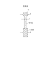
- the plurality of rod-shaped portions 53 are arranged such that the direction of the component force directed to the space S in the arch-shaped portion 4 matches the direction of the axial force of the rod-shaped portion 53. Is connected. Thereby, the strength (durability) of the arch-shaped portion 4 is improved.
- the present invention is not limited to this embodiment.
- the thickness of the rod-shaped portion 53 may be adjusted instead of adjusting the thickness of the rod-shaped portion 53 as described above. That is, the number of the bar-like parts 53 positioned on the side where a larger force acts may be increased, and the same effect as when adjusting the thickness of the plurality of bar-like parts 53 can be achieved.
- the thickness of all the rod-shaped parts 53 may be the same.
- the plurality of rod-shaped portions 53 may be composed of two or more rod-shaped portions 53.
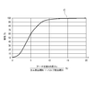
- the separation distance Is continuously decreases from the apex portion 4p toward the end of the valve side arm portion 33 in the arch-shaped portion 4.
- the separation distance Is continuously increases from the end of the cam side arm portion 32 in the arch-shaped portion 4 toward the apex portion 4p.
- the separation distance Is continuously decreases from the apex portion 4p toward the end portion of the cam side arm portion 32 in the arch-shaped portion 4. That is, in the arch-shaped portion 4, the line connecting the cam side end portion 32e (for example, the cam side load application point Pc), the apex portion 4p and the valve side end portion 33e (for example, the valve side load application point Pv) has an arc shape. It has a shape that becomes a bow shape.
Landscapes
- Engineering & Computer Science (AREA)
- Mechanical Engineering (AREA)
- General Engineering & Computer Science (AREA)
- Valve-Gear Or Valve Arrangements (AREA)
Abstract
L'invention concerne un culbuteur supporté par un arbre de bras d'une manière basculable et actionnant une soupape par la rotation d'une came. Le culbuteur est pourvu : d'un corps de bras ayant une section de support qui est supportée par l'arbre de bras, une section de bras côté came qui s'étend vers un côté à partir de la section de palier, et une section de bras côté soupape qui s'étend vers l'autre côté à partir de la section de palier; une section en forme d'arc pour relier la section de bras côté came et la section de bras côté soupape tout en chevauchant la section de support; et une section de poids réduit disposée dans un espace défini entre le corps de bras et la section en forme d'arc et dont on note une réduction de poids par rapport à des cas où l'espace est rempli avec le même matériau et à la même épaisseur que la section en forme d'arc.
Priority Applications (2)
| Application Number | Priority Date | Filing Date | Title |
|---|---|---|---|
| US16/097,326 US11131219B2 (en) | 2016-10-20 | 2017-10-20 | Rocker arm |
| EP17861358.4A EP3447259B1 (fr) | 2016-10-20 | 2017-10-20 | Culbuteur |
Applications Claiming Priority (2)
| Application Number | Priority Date | Filing Date | Title |
|---|---|---|---|
| JP2016-206287 | 2016-10-20 | ||
| JP2016206287A JP6831207B2 (ja) | 2016-10-20 | 2016-10-20 | ロッカーアーム |
Publications (1)
| Publication Number | Publication Date |
|---|---|
| WO2018074596A1 true WO2018074596A1 (fr) | 2018-04-26 |
Family
ID=62018818
Family Applications (1)
| Application Number | Title | Priority Date | Filing Date |
|---|---|---|---|
| PCT/JP2017/038037 Ceased WO2018074596A1 (fr) | 2016-10-20 | 2017-10-20 | Culbuteur |
Country Status (4)
| Country | Link |
|---|---|
| US (1) | US11131219B2 (fr) |
| EP (1) | EP3447259B1 (fr) |
| JP (1) | JP6831207B2 (fr) |
| WO (1) | WO2018074596A1 (fr) |
Citations (8)
| Publication number | Priority date | Publication date | Assignee | Title |
|---|---|---|---|---|
| JPS59208112A (ja) * | 1983-05-12 | 1984-11-26 | Atsugi Motor Parts Co Ltd | ラツシユ調整可能なバルブロツカア−ム |
| JPS59179205U (ja) * | 1983-05-19 | 1984-11-30 | 日産自動車株式会社 | 内燃機関の動弁装置 |
| JPS6014211U (ja) * | 1983-07-08 | 1985-01-30 | 日産自動車株式会社 | 自動車用機関の動弁機構 |
| JPS6178204U (fr) * | 1984-10-30 | 1986-05-26 | ||
| JPS6290904U (fr) | 1985-11-28 | 1987-06-10 | ||
| JP2001055911A (ja) | 1999-08-12 | 2001-02-27 | Suzuki Motor Corp | ロッカアームの形状 |
| JP2002322903A (ja) * | 2001-03-30 | 2002-11-08 | Caterpillar Inc | ロッカーアーム組立体 |
| JP2016098906A (ja) * | 2014-11-21 | 2016-05-30 | Ntn株式会社 | 歯車およびこれを備えた電動アクチュエータ |
Family Cites Families (22)
| Publication number | Priority date | Publication date | Assignee | Title |
|---|---|---|---|---|
| US636070A (en) * | 1899-05-15 | 1899-10-31 | Robert C Schenck | Brake-lever. |
| US4473047A (en) * | 1980-02-25 | 1984-09-25 | The Jacobs Mfg. Company | Compression release engine brake |
| JPS59137309U (ja) | 1983-03-03 | 1984-09-13 | 日産自動車株式会社 | ロツカア−ムの軸受構造 |
| JPS59159710U (ja) | 1983-04-11 | 1984-10-26 | 日産自動車株式会社 | 内燃機関の動弁装置 |
| JPS6077708U (ja) | 1983-06-30 | 1985-05-30 | いすゞ自動車株式会社 | オ−トアジヤスタ付ロツカーアーム |
| JPS6065212A (ja) | 1983-09-19 | 1985-04-15 | Toyota Motor Corp | 繊維強化樹脂製ロツカア−ム |
| US5185923A (en) * | 1989-06-16 | 1993-02-16 | Ngk Spark Plug Co., Ltd. | Method of making a frictionally sliding component |
| IT1255447B (it) * | 1991-11-08 | 1995-10-31 | Iveco Fiat | Motore provvisto di un dispositivo di frenatura continua, particolarmente per un veicolo industriale. |
| JPH0573211U (ja) | 1992-03-03 | 1993-10-08 | 三菱重工業株式会社 | 内燃機関用動弁装置 |
| IT1291490B1 (it) * | 1997-02-04 | 1999-01-11 | C R F Societa Consotile Per Az | Motore pluricilindrico a ciclo diesel con valvole ad azionamento variabile |
| DE19756580A1 (de) * | 1997-06-21 | 1998-12-24 | Samsung Heavy Ind | Motorstössel mit hoher Verschleißfestigkeit und Verfahren zum Herstellen desselben |
| US7559301B2 (en) * | 2002-07-01 | 2009-07-14 | Cinetic Automation Corporation | Valve lash adjustment and inspection apparatus |
| US7398752B2 (en) | 2004-12-13 | 2008-07-15 | Weaver Robert R | Rocker arm for valve actuation |
| US20080271692A1 (en) * | 2004-12-13 | 2008-11-06 | Weaver Robert R | Rocker arm for valve actuation |
| US7185618B1 (en) * | 2006-01-12 | 2007-03-06 | Gentek Technologies Marketing Inc. | Sheet metal rocker arm with integrally formed cross member |
| US7412952B2 (en) | 2006-12-08 | 2008-08-19 | Ford Global Technologies, Llc | Poppet valve operating system for internal combustion engine |
| US20080229578A1 (en) * | 2007-03-20 | 2008-09-25 | Gentek Technologies Marketing Inc. | Rocker arm with integral internal oil passages |
| EP2386729A1 (fr) * | 2010-05-10 | 2011-11-16 | Fiat Powertrain Technologies S.p.A. | Moteur à combustion interne multicylindres ayant un actionnement variable des soupapes du moteur |
| DE102013215538B4 (de) | 2013-08-07 | 2015-02-19 | Federal-Mogul Nürnberg GmbH | Kolben für einen Verbrennungsmotor |
| US20160138436A1 (en) * | 2014-11-18 | 2016-05-19 | Caterpillar Inc. | Method of remanufacturing a rocker arm and a remanufactured rocker arm |
| US9551242B2 (en) * | 2014-11-24 | 2017-01-24 | Caterpillar Inc. | Rocker arm for engines |
| JP6222708B2 (ja) | 2015-09-30 | 2017-11-01 | 本田技研工業株式会社 | 内燃機関 |
-
2016
- 2016-10-20 JP JP2016206287A patent/JP6831207B2/ja not_active Expired - Fee Related
-
2017
- 2017-10-20 EP EP17861358.4A patent/EP3447259B1/fr active Active
- 2017-10-20 US US16/097,326 patent/US11131219B2/en not_active Expired - Fee Related
- 2017-10-20 WO PCT/JP2017/038037 patent/WO2018074596A1/fr not_active Ceased
Patent Citations (8)
| Publication number | Priority date | Publication date | Assignee | Title |
|---|---|---|---|---|
| JPS59208112A (ja) * | 1983-05-12 | 1984-11-26 | Atsugi Motor Parts Co Ltd | ラツシユ調整可能なバルブロツカア−ム |
| JPS59179205U (ja) * | 1983-05-19 | 1984-11-30 | 日産自動車株式会社 | 内燃機関の動弁装置 |
| JPS6014211U (ja) * | 1983-07-08 | 1985-01-30 | 日産自動車株式会社 | 自動車用機関の動弁機構 |
| JPS6178204U (fr) * | 1984-10-30 | 1986-05-26 | ||
| JPS6290904U (fr) | 1985-11-28 | 1987-06-10 | ||
| JP2001055911A (ja) | 1999-08-12 | 2001-02-27 | Suzuki Motor Corp | ロッカアームの形状 |
| JP2002322903A (ja) * | 2001-03-30 | 2002-11-08 | Caterpillar Inc | ロッカーアーム組立体 |
| JP2016098906A (ja) * | 2014-11-21 | 2016-05-30 | Ntn株式会社 | 歯車およびこれを備えた電動アクチュエータ |
Also Published As
| Publication number | Publication date |
|---|---|
| EP3447259B1 (fr) | 2020-07-15 |
| EP3447259A4 (fr) | 2019-08-07 |
| EP3447259A1 (fr) | 2019-02-27 |
| US11131219B2 (en) | 2021-09-28 |
| JP2018066344A (ja) | 2018-04-26 |
| US20190093523A1 (en) | 2019-03-28 |
| JP6831207B2 (ja) | 2021-02-17 |
Similar Documents
| Publication | Publication Date | Title |
|---|---|---|
| JP2009108708A (ja) | マルチリンクエンジンのリンクジオメトリ | |
| WO2018074596A1 (fr) | Culbuteur | |
| JP4992770B2 (ja) | 内燃機関のピストンクランク機構におけるロアリンク | |
| US7673602B2 (en) | Variable valve mechanism | |
| JP2005291007A (ja) | エンジンの可変動弁装置 | |
| JP4546427B2 (ja) | 内燃機関の可変動弁機構 | |
| US20070017461A1 (en) | Valve train and cam lobe | |
| JP2008150973A (ja) | 内燃機関の可変動弁装置 | |
| JP2012219629A (ja) | エンジン | |
| JP2008190446A (ja) | エンジンの可変動弁装置 | |
| JP2004108252A (ja) | バルブ制御機構 | |
| US7556006B2 (en) | Valve mechanism of engine | |
| WO2016103923A1 (fr) | Culbuteur et procédé de fabrication de culbuteur | |
| JP5273264B2 (ja) | 内燃機関のピストンクランク機構におけるロアリンク | |
| JP7572727B2 (ja) | 内燃機関の動弁機構 | |
| JP4715763B2 (ja) | エンジンの可変動弁装置 | |
| JP5239605B2 (ja) | 可変動弁装置及び内燃機関 | |
| JP2010133374A (ja) | 可変圧縮比エンジンのコントロールシャフト | |
| JP2007113419A (ja) | 連続可変動弁機構 | |
| JP7112906B2 (ja) | 複リンク式ピストンクランク機構 | |
| JP2008240633A (ja) | エンジンの動弁装置 | |
| JP6182079B2 (ja) | 内燃機関の動弁機構 | |
| CN107869367A (zh) | 一种压电驱动的杠杆式无凸轮轴气门驱动机构 | |
| JP2010059915A (ja) | 内燃機関の可変動弁機構 | |
| JP5304878B2 (ja) | マルチリンクエンジンのリンクジオメトリ |
Legal Events
| Date | Code | Title | Description |
|---|---|---|---|
| 121 | Ep: the epo has been informed by wipo that ep was designated in this application |
Ref document number: 17861358 Country of ref document: EP Kind code of ref document: A1 |
|
| ENP | Entry into the national phase |
Ref document number: 2017861358 Country of ref document: EP Effective date: 20181121 |
|
| NENP | Non-entry into the national phase |
Ref country code: DE |