WO2018092301A1 - Climatiseur - Google Patents
Climatiseur Download PDFInfo
- Publication number
- WO2018092301A1 WO2018092301A1 PCT/JP2016/084418 JP2016084418W WO2018092301A1 WO 2018092301 A1 WO2018092301 A1 WO 2018092301A1 JP 2016084418 W JP2016084418 W JP 2016084418W WO 2018092301 A1 WO2018092301 A1 WO 2018092301A1
- Authority
- WO
- WIPO (PCT)
- Prior art keywords
- absorbing material
- sound absorbing
- compressor
- base plate
- sound
- Prior art date
- Legal status (The legal status is an assumption and is not a legal conclusion. Google has not performed a legal analysis and makes no representation as to the accuracy of the status listed.)
- Ceased
Links
Images


Classifications
-
- F—MECHANICAL ENGINEERING; LIGHTING; HEATING; WEAPONS; BLASTING
- F24—HEATING; RANGES; VENTILATING
- F24F—AIR-CONDITIONING; AIR-HUMIDIFICATION; VENTILATION; USE OF AIR CURRENTS FOR SCREENING
- F24F1/00—Room units for air-conditioning, e.g. separate or self-contained units or units receiving primary air from a central station
- F24F1/06—Separate outdoor units, e.g. outdoor unit to be linked to a separate room comprising a compressor and a heat exchanger
- F24F1/08—Compressors specially adapted for separate outdoor units
- F24F1/12—Vibration or noise prevention thereof
-
- F—MECHANICAL ENGINEERING; LIGHTING; HEATING; WEAPONS; BLASTING
- F24—HEATING; RANGES; VENTILATING
- F24F—AIR-CONDITIONING; AIR-HUMIDIFICATION; VENTILATION; USE OF AIR CURRENTS FOR SCREENING
- F24F13/00—Details common to, or for air-conditioning, air-humidification, ventilation or use of air currents for screening
- F24F13/24—Means for preventing or suppressing noise
Definitions
- the present invention relates to an air conditioner including an outdoor unit having a compressor covered with a soundproof cover.
- a compressor as a main part generates a large noise. Therefore, the compressor is surrounded by a soundproof cover to enhance the sealing effect and take measures against noise.
- a soundproof cover of a compressor there is one constituted by an outer layer side waterproof sheet member and an inner layer side sound absorbing felt member whose lower end is provided at a position higher than a base plate by a predetermined dimension (for example, a patent) Reference 1).
- a soundproof cover a sound insulating material that covers the side surface of the compressor with the lower end portion installed on the base plate, and a side surface of the compressor at a position inside the sound insulating material and above the lower end portion of the sound insulating material.
- the present invention has been made to solve the above-described problems, and prevents noise generated during operation of the compressor and corrosion of the compressor, as well as self-supporting soundproof covers due to vibration during operation of the compressor. It aims at obtaining the air conditioner which can prevent instability and a deformation
- An air conditioner is an air conditioner including an outdoor unit having a compressor installed on a base plate, a sound absorbing material covering the periphery of the compressor, and a sound absorbing material covering the periphery of the sound absorbing material.
- the sound absorbing material includes a first sound absorbing material having a lower end positioned above the base plate and covering the periphery of the compressor, and a lower end portion of the first sound absorbing material. It is comprised with the 2nd sound-absorbing material installed in the base plate at a distance.
- the soundproof cover includes a sound absorbing material that covers the periphery of the compressor, and a waterproof material that covers the periphery of the sound absorbing material and is installed on the base plate, and the sound absorbing material has a lower end portion above the base plate. And a second sound absorbing material installed on the base plate with a gap from the lower end of the first sound absorbing material.
- the second sound absorbing material and the waterproof material are installed on the base plate, the installation area of the second sound absorbing material and the waterproof material on the base plate can be increased. Thereby, the independence of the soundproof cover can be improved, and the deformation of the soundproof cover due to the vibration of the compressor can be suppressed with the improvement of the independence of the soundproof cover.
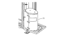
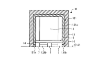
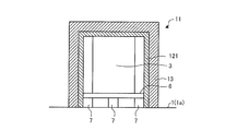
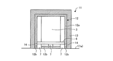
- FIG. 1 It is a perspective view which shows the main components of the outdoor unit of the air conditioner which concerns on Embodiment 1 of this invention. It is a perspective view which shows the external appearance of the soundproof cover of the compressor of FIG. It is sectional drawing which shows the structure of the soundproof cover of FIG. It is a bottom view which shows the soundproof cover of FIG. 2 and the support stand of a compressor seeing from the bottom. It is sectional drawing which shows the structure of the soundproof cover of the compressor in the outdoor unit of the air conditioner which concerns on Embodiment 2 of this invention. It is sectional drawing which shows the structure of the soundproof cover of the compressor in the outdoor unit of the air conditioner which concerns on Embodiment 3 of this invention. It is sectional drawing which shows the modification of the soundproof cover of FIG.
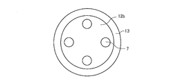
- FIG. 9 is a bottom view showing the soundproof cover and the second sound absorbing material of FIG. 8 as viewed from below. It is sectional drawing which shows the modification of the soundproof cover of FIG. It is sectional drawing which shows the structure of the soundproof cover of the compressor in the outdoor unit of the air conditioner which concerns on Embodiment 5 of this invention. It is sectional drawing which shows the structure of the soundproof cover of the compressor in the outdoor unit of the air conditioner which concerns on Embodiment 6 of this invention.
- FIG. 1 is a perspective view showing main parts of an outdoor unit of an air conditioner according to Embodiment 1 of the present invention
- FIG. 2 is a perspective view showing an appearance of a soundproof cover of the compressor of FIG.
- the base plate 1 of the outdoor unit 100 is divided by a partition plate 2.
- a compressor 3 In one region of the base plate 1 divided by the partition plate 2, a compressor 3, an accumulator 4 attached to the compressor 3, a four-way valve (not shown), and the like are arranged.
- a four-way valve (not shown), and the like are arranged in the other region of the base plate 1.
- blower 8 not shown
- the compressor 3, the four-way valve, the heat exchanger 5, the accumulator 4 and the like are connected by piping.
- the base plate 1 is uneven, and a convex surface 1a and a concave surface 1b are formed by the unevenness.
- Anti-vibration rubber 7 attached as legs to the support base 6 of the compressor 3 is installed on the convex surface 1 a of the base plate 1 and suppresses vibrations generated during operation of the compressor 3.
- the compressor 3 is covered with a soundproof cover 11 together with the accumulator 4.
- the vibration-proof rubber 7 is used as a leg part of the compressor 3, if it supports the compressor 3 and suppresses a vibration, it will not be limited to rubber
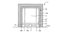
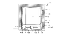
- FIG. 3 is a cross-sectional view showing the structure of the soundproof cover of FIG. 2
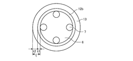
- FIG. 4 is a bottom view of the soundproof cover and the support base of the compressor of FIG.
- FIG. 3 is a cross-sectional view showing the structure of the soundproof cover of FIG. 2
- FIG. 4 is a bottom view of the soundproof cover and the support base of the compressor of FIG.
- the soundproof cover 11 includes a sound absorbing material 12 that covers the periphery except the lower side of the compressor 3, and a waterproof material 13 that covers the periphery of the sound absorbing material 12 and is installed on the base plate 1.
- the sound absorbing material 12 is formed of, for example, a single felt, the lower end portion of the sound absorbing material 12 is located above the base plate 1, and the first sound absorbing material 12a covering the periphery of the compressor 3 and the lower end portion of the first sound absorbing material 12a. It is comprised with the 2nd sound-absorbing material 12b installed in the base board 1 across the clearance gap 14.
- the sound absorbing material 12 is composed of a first sound absorbing material 12a and a second sound absorbing material 12b which are divided vertically with a gap 14 positioned on the upper side of the side surface of the vibration isolating rubber 7 as a boundary.
- the first sound-absorbing material 12a covers the upper surface of the compressor 3, and covers the side surface of the compressor 3 with a space therebetween with the outer diameter of the support base 6 as an inner diameter.
- the first sound absorbing material 12 a is covered with the upper surface of the compressor 3, but the upper surface of the compressor 3 may be covered with a space.
- the second sound absorbing material 12 b described above is formed in a ring shape and is disposed between the vibration-proof rubber 7 and the inner peripheral surface of the lower end portion of the waterproof material 13.
- the waterproof material 13 is made of rubber, for example, and covers the first sound absorbing material 12a and the second sound absorbing material 12b including the gap 14 in a state where the waterproof material 13 is in contact with the outer peripheral surfaces of the first sound absorbing material 12a and the second sound absorbing material 12b. .
- the second sound absorbing material 12b and the waterproof material 13 are installed on the convex surface 1a formed on the base plate 1 in a state where they are in contact with each other as described above.
- the thickness as the sound-insulation cover 11 is thick. That is, as shown in FIG. 4, the thickness t of the soundproof cover 11 is a thickness obtained by adding the thickness t1 of the second sound absorbing material 12 b to the thickness t2 of the waterproof material 13. The installation area is widened.
- the condensation generated by the operation of the outdoor unit 100 drops on the base plate 1 and is exposed to rain and wind, water accumulates in the base plate 1.
- the water is absorbed by the second sound absorbing material 12b.
- the water absorbed by the second sound absorbing material 12b rises against gravity due to the capillary phenomenon, but remains in the second sound absorbing material 12b by the gap 14 between the first sound absorbing material 12a and the second sound absorbing material 12b,
- the sound absorbing material 12a does not penetrate. That is, since the rise of water due to the capillary phenomenon is blocked by the gap 14, water does not adhere to the compressor 3.
- the gap 14 is provided in the sound absorbing material 12 of the soundproof cover 11 that covers the periphery of the compressor 3, even when water accumulates on the base plate 1, Remains absorbed by the second sound absorbing material 12b. For this reason, corrosion of the compressor 3 can be prevented while maintaining the soundproofing effect.
- the installation area of the second sound absorbing material 12b and the waterproof material 13 on the base plate 1 can be widened.
- the independence of the soundproof cover 11 can be improved, and the deformation of the soundproof cover 11 due to the vibration of the compressor 3 can be suppressed as the independence of the soundproof cover 11 is improved.
- the soundproof cover 11 can produce the 1st sound absorption material 12a and the 2nd sound absorption material 12b only by cut
- the sound absorbing material 12 may be formed by dividing the felt into a plurality of pieces in the circumferential direction of the compressor 3 or may be formed by winding the felt several times.
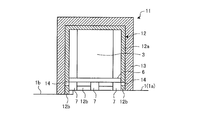
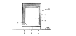
- FIG. FIG. 5 is a cross-sectional view showing a configuration of a soundproof cover of a compressor in an outdoor unit of an air conditioner according to Embodiment 2 of the present invention.
- the same parts as those in the first embodiment shown in FIGS. 1 to 4 are denoted by the same reference numerals.
- the installation surface of the soundproof cover 11 is formed according to the shape of the base plate 1. That is, the installation surface installed on the base plate 1 of the second sound absorbing material 12b and the waterproof material 13 is uneven so as to be fitted to the convex surface 1a and the concave surface 1b formed on the base plate 1.
- the first sound absorbing material 12a covers the upper surface of the compressor 3, and covers the side surface of the compressor 3 with the outer diameter of the support base 6 as an inner diameter with a space therebetween.
- the first sound-absorbing material 12 a is covered with the upper surface of the compressor 3, but the upper surface of the compressor 3 may be covered with a space.
- the second sound absorbing material 12 b is formed in a ring shape, and is disposed between the vibration isolating rubber 7 and the inner peripheral surface of the lower end portion of the waterproof material 13.
- the installation surfaces of the second sound absorbing material 12b and the waterproof material 13 are installed by being fitted to the convex surface 1a and the concave surface 1b formed on the base plate 1.
- the compressor 3 can be completely covered with the base plate 1 and the soundproof cover 11.
- the air tightness is improved, as a result, the sound insulation is improved, and the installation area of the second sound absorbing material 12b and the waterproof material 13 is also set as compared with the first embodiment in which only the convex surface 1a of the base plate 1 is installed. This greatly increases, and the stability of the soundproof cover 11 is also increased.
- the water accumulated on the base plate 1 is absorbed by the second sound absorbing material 12b and does not reach the first sound absorbing material 12a provided with the gap 14 therebetween.
- the installation surfaces of the second sound absorbing material 12b and the waterproof material 13 are installed so as to be fitted to the convex surface 1a and the concave surface 1b formed on the base plate 1, and the gap 14 is separated.
- the compressor 3 is covered with the first sound absorbing material 12a, and the first sound absorbing material 12a is covered with the waterproof material 13 in contact with the first sound absorbing material 12a. With this configuration, the soundproofing effect is improved and corrosion of the compressor 3 can be prevented.
- the installation surface of the second sound absorbing material 12b and the waterproof material 13 is installed by being fitted to the convex surface 1a and the concave surface 1b of the base plate 1, so that the installation area is significantly larger than that of the first embodiment. Can be wide.
- the independence of the soundproof cover 11 can be further enhanced, and the deformation of the soundproof cover 11 due to the vibration of the compressor 3 can be suppressed as the independence of the soundproof cover 11 is improved.
- the soundproof cover 11 can produce the 1st sound absorption material 12a and the 2nd sound absorption material 12b only by cut
- FIG. FIG. 6 is a cross-sectional view showing a configuration of a soundproof cover of a compressor in an outdoor unit of an air conditioner according to Embodiment 3 of the present invention.
- the same parts as those in the first embodiment shown in FIGS. 1 to 4 are denoted by the same reference numerals.
- a sound absorbing material 121 formed of a water repellent material, for example, HB felt is used for the soundproof cover 11 in the third embodiment.
- the sound absorbing material 121 is divided into a first sound absorbing material 121a and a second sound absorbing material 121b in the vertical direction with a gap 14 positioned on the upper side of the side surface of the vibration isolating rubber 7 as a boundary.
- the first sound-absorbing material 121a covers the upper surface of the compressor 3, and covers the side surface of the compressor 3 with a space therebetween with the outer diameter of the support base 6 as an inner diameter.
- the first sound-absorbing material 121a is covered with the upper surface of the compressor 3, but the upper surface of the compressor 3 may be covered with a space.
- the second sound absorbing material 121b is formed in a ring shape, and is disposed between the vibration isolating rubber 7 and the inner peripheral surface of the lower end portion of the waterproof material 13. If a material having a contact angle with water of 90 ° or more is used as the second sound absorbing material 121b, the effect of suppressing the rise in liquid level can be increased. That is, when the contact angle with water becomes 90 ° or more, the liquid level does not rise. Further, since the above-described sound absorbing material 121 has water repellency and flame retardancy, it can be used around the compressor 3 that becomes high temperature.
- the gap 14 is provided between the first sound absorbing material 121a and the second sound absorbing material 121b, and the first sound absorbing material 121a and the second sound absorbing material 121b are repelled. It is made of a water-based material. Thereby, even when water accumulates on the base plate 1, the water is not absorbed by the second sound absorbing material 121 b and is blocked by the gap 14, so that it reaches the compressor 3. Can be reliably suppressed, and corrosion of the compressor 3 can be prevented.
- the second sound absorbing material 121b and the waterproof material 13 are installed on the base plate 1, the installation area of the second sound absorbing material 121b and the waterproof material 13 on the base plate 1 can be widened. Thereby, the independence of the soundproof cover 11 can be improved, and the deformation of the soundproof cover 11 due to the vibration of the compressor 3 can be suppressed as the independence of the soundproof cover 11 is improved. Moreover, since the soundproof cover 11 can produce the 1st sound absorption material 12a and the 2nd sound absorption material 12b only by cut
- the sound absorbing material 121 having water repellency is shown as an example divided up and down with the gap 14 as a boundary.
- FIG. 7 is a sectional view showing a modification of the soundproof cover of FIG.
- the sound absorbing material 121 shown in FIG. 7 is made of a material (HB felt) having water repellency and flame retardancy. If a material having a contact angle with water of 90 ° or more is used as the sound absorbing material 121, the effect of suppressing the rise in liquid level can be increased.
- the sound absorbing material 121 can cover the periphery of the compressor 3 with a space therebetween, with the upper surface of the compressor 3 and the outer diameter of the support base 6 as the inner diameter, without providing the gap 14.
- the sound absorbing material 121 is covered with the upper surface of the compressor 3, but the upper surface of the compressor 3 may be covered with a space. With this configuration, it is possible to prevent corrosion of the compressor 3 while securing an installation area without providing the gap 14 in the sound absorbing material 121.
- FIG. FIG. 8 is a cross-sectional view showing a configuration of a soundproof cover of a compressor in an outdoor unit of an air conditioner according to Embodiment 4 of the present invention
- FIG. 9 shows the soundproof cover and the second sound absorbing material of FIG. It is a bottom view.
- the same parts as those in the first embodiment shown in FIGS. 1 to 4 are denoted by the same reference numerals.
- the second sound absorbing material 12b has a circular outer shape through which the vibration isolating rubber 7 penetrates.
- the outer diameter of the second sound absorbing material 12b is such that the second sound absorbing material 12b fits into the inner diameter of the waterproof material 13, as shown in FIG.
- the second sound absorbing material 12 b is located in a portion of the base plate 1 that is covered with the waterproof material 13.
- FIG. In FIG. 8, the first sound absorbing material 12 a is covered with the upper surface of the compressor 3, but the upper surface of the compressor 3 may be covered with a space.
- the entire compressor 3 can be covered with the first sound absorbing material 12a and the second sound absorbing material 12b, so that the soundproofing effect can be further enhanced. Moreover, since the clearance 14 is provided in the sound absorbing material 12, even when water accumulates on the base plate 1, the water is absorbed and retained by the second sound absorbing material 12b, and corrosion of the compressor 3 can be prevented.
- the installation area of the second sound absorbing material 12b and the waterproof material 13 on the base plate 1 is further increased. be able to.
- the independence of the soundproof cover 11 can be further enhanced, and the deformation of the soundproof cover 11 due to the vibration of the compressor 3 can be suppressed as the independence of the soundproof cover 11 is improved.
- the soundproof cover 11 can produce the 1st sound absorption material 12a and the 2nd sound absorption material 12b only by cut
- FIG. 10 is a sectional view showing a modification of the soundproof cover of FIG.
- the sound absorbing material 12 in this modification is composed of a first sound absorbing material 12a, a ring-shaped second sound absorbing material 12b, and a third sound absorbing material 12c.
- the third sound absorbing material 12 c is formed in the same shape as the shape on the installation surface side of the waterproof material 13 and is attached to the back surface of the base plate 1.
- the 3rd sound-absorbing material 12c is provided in the part facing the waterproof material 13 of the back surface of the base board 1, the whole compressor 3 was covered with the 1st sound-absorbing material 12a and the 2nd sound-absorbing material 12b. It becomes a state. Thereby, the soundproofing effect can be further enhanced and the deformation of the soundproof cover 11 due to the vibration of the compressor 3 can be suppressed. Moreover, since the clearance 14 is provided in the sound absorbing material 12, even when water accumulates on the base plate 1, the water is absorbed and retained by the second sound absorbing material 12b, and corrosion of the compressor 3 can be prevented.
- FIG. FIG. 11 is sectional drawing which shows the structure of the soundproof cover of the compressor in the outdoor unit of the air conditioner concerning Embodiment 5 of this invention.
- the same parts as those in the first embodiment shown in FIGS. 1 to 4 are denoted by the same reference numerals.
- the soundproof cover 11 is installed around the compressor 3 of the support base 6.
- the compressor 3 is installed on the convex surface 1 a of the base plate 1 via a support base 6 and a vibration isolating rubber 7.
- the sound absorbing material 12 is covered in contact with the upper surface and side surfaces of the compressor 3, and the waterproof material 13 is covered in contact with the upper surface and side surfaces of the sound absorbing material 12.
- the sound absorbing material 12 is brought into contact with the upper surface and the side surface of the compressor 3, but the upper surface and the side surface of the compressor 3 may be covered with a space therebetween.
- the soundproof cover 11 is installed on the support base 6 of the compressor 3, even if water accumulates on the base plate 1, the water is absorbed by the sound absorbing material 12. It is not sucked up and corrosion of the compressor 3 can be prevented. Moreover, since the compressor 3 is covered in the state in which the soundproof cover 11 is installed on the support base 6, airtightness can be maintained, and the soundproofing effect can be further enhanced.
- the sound absorbing material 12 and the waterproof material 13 are installed on the support base 6, a large installation area as the soundproof cover 11 can be taken. Thereby, the stable independence of the soundproof cover can be improved, and the deformation of the soundproof cover 11 due to the vibration of the compressor 3 can be suppressed with the improvement of the independence of the soundproof cover 11.
- FIG. FIG. 12 is a cross-sectional view showing a configuration of a soundproof cover of a compressor in an outdoor unit of an air conditioner according to Embodiment 6 of the present invention.
- the same parts as those in the first embodiment shown in FIGS. 1 to 4 are denoted by the same reference numerals.
- a sheet material 15 is provided between the base plate 1 and the soundproof cover 11.
- This sheet material 15 has waterproofness, fire resistance, and stretchability, has a U-shaped cross section, and is formed in a ring shape.
- the lower end portion of the waterproof material 13 and the ring-shaped second sound absorbing material 12 b are inserted, and the lower end portion of the first sound absorbing material 12 a is inserted with the gap 14 maintained. Since the sheet material 15 has elasticity as described above, the space between the outer peripheral surface of the lower end portion of the waterproof material 13 is sealed. Thereby, even if the outer peripheral surface of the waterproof material 13 gets wet due to the intrusion of rainwater into the outdoor unit 100, water does not enter between the sheet material 15 and the waterproof material 13.
- the sheet material 15 is provided between the base plate 1 and the soundproof cover 11 so that water is not absorbed by the second sound absorbing material 12b, and the first sound absorbing material 12a. Since the gap 14 is provided between the first sound absorbing material 12b and the second sound absorbing material 12b, the corrosion resistance of the compressor 3 can be improved while maintaining the soundproofing effect.
- the installation area of the base plate 1 as the soundproof cover 11 is widened. can do.
- the independence of the soundproof cover 11 can be enhanced, and the deformation of the soundproof cover 11 due to the vibration of the compressor 3 can be suppressed as the independence of the soundproof cover 11 is improved.
- only the sheet material 15 is added, there is an effect that the manufacturing is easy and the cost is low.
- the gap 14 is provided between the first sound absorbing material 12a and the second sound absorbing material 12b, but the sheet material 15 is provided between the base plate 1 and the soundproof cover 11. Therefore, the sound absorbing material 12 without the gap 14 may be used.
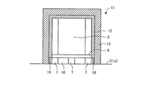
- FIG. FIG. 13 is a cross-sectional view showing a configuration of a soundproof cover of a compressor in an outdoor unit of an air conditioner according to Embodiment 7 of the present invention
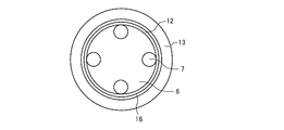
- FIG. 14 shows the soundproof cover and the support base of the compressor of FIG. It is a bottom view shown.
- the same parts as those in the first embodiment shown in FIGS. 1 to 4 are denoted by the same reference numerals.
- an auxiliary support material 16 is provided between the lower end portion of the sound absorbing material 12 and the base plate 1.
- the auxiliary support member 16 is made of the same material as that of the vibration-proof rubber 7 that is a leg portion of the compressor 3, for example, and is formed in a ring shape.
- the auxiliary support member 16 is installed on the base plate 1 in a state in contact with the inner peripheral surface of the lower end portion of the waterproof material 13.
- the auxiliary support member 16 prevents the sound absorbing material 12 from touching the base plate 1 and increases the installation area with the base plate 1 as the soundproof cover 11.
- the sound-absorbing material 12 is covered with the upper surface of the compressor 3, but the upper surface of the compressor 3 may be covered with a space.
- the auxiliary support member 16 is provided at the lower end of the sound absorbing material 12 of the soundproof cover 11 that covers the periphery of the compressor 3.
- the installation area with the base plate 1 as the soundproof cover 11 can be widened.
- the independence of the soundproof cover 11 can be improved, and the deformation of the soundproof cover 11 due to the vibration of the compressor 3 can be suppressed as the independence of the soundproof cover 11 is improved.
- the soundproof cover 11 can be created simply by adding the auxiliary support material 16 to the sound absorbing material 12 made from a single piece of felt, there is also an effect that the production is easy and the cost is low.
- the felt is used for the first sound absorbing material 12a and the second sound absorbing material 12b, but may be formed of a material having water repellency.
- the configuration of the soundproof cover 11 that covers only the compressor 3 has been described.
- the compressor 3 including the accumulator 4 can be easily covered only by making the shape of the soundproof cover 11 elliptical. Can do.
Landscapes
- Engineering & Computer Science (AREA)
- Chemical & Material Sciences (AREA)
- Combustion & Propulsion (AREA)
- Mechanical Engineering (AREA)
- General Engineering & Computer Science (AREA)
- Compressor (AREA)
Abstract
La présente invention concerne un climatiseur qui est pourvu d'une unité extérieure ayant un compresseur monté sur une plaque de base, d'un couvercle insonorisant ayant un matériau insonorisant recouvrant la périphérie du compresseur et un matériau étanche à l'eau recouvrant la périphérie du matériau insonorisant et monté sur la plaque de base. Le matériau insonorisant est formé par un premier matériau insonorisant recouvrant la périphérie du compresseur et ayant une partie d'extrémité inférieure placée sur la plaque de base, et par un second matériau insonorisant monté sur la plaque de base et séparé par un vide de la partie d'extrémité inférieure du premier matériau insonorisant.
Priority Applications (2)
| Application Number | Priority Date | Filing Date | Title |
|---|---|---|---|
| JP2018550994A JPWO2018092301A1 (ja) | 2016-11-21 | 2016-11-21 | 空気調和機 |
| PCT/JP2016/084418 WO2018092301A1 (fr) | 2016-11-21 | 2016-11-21 | Climatiseur |
Applications Claiming Priority (1)
| Application Number | Priority Date | Filing Date | Title |
|---|---|---|---|
| PCT/JP2016/084418 WO2018092301A1 (fr) | 2016-11-21 | 2016-11-21 | Climatiseur |
Publications (1)
| Publication Number | Publication Date |
|---|---|
| WO2018092301A1 true WO2018092301A1 (fr) | 2018-05-24 |
Family
ID=62145377
Family Applications (1)
| Application Number | Title | Priority Date | Filing Date |
|---|---|---|---|
| PCT/JP2016/084418 Ceased WO2018092301A1 (fr) | 2016-11-21 | 2016-11-21 | Climatiseur |
Country Status (2)
| Country | Link |
|---|---|
| JP (1) | JPWO2018092301A1 (fr) |
| WO (1) | WO2018092301A1 (fr) |
Cited By (1)
| Publication number | Priority date | Publication date | Assignee | Title |
|---|---|---|---|---|
| DE102021205746A1 (de) | 2021-06-08 | 2022-12-08 | Robert Bosch Gesellschaft Für Medizinische Forschung Mbh | Wärmepumpe mit einem Bodengestell |
Citations (9)
| Publication number | Priority date | Publication date | Assignee | Title |
|---|---|---|---|---|
| JPH0173529U (fr) * | 1987-11-02 | 1989-05-18 | ||
| JPH0297833A (ja) * | 1988-10-04 | 1990-04-10 | Mitsubishi Electric Corp | 空気調和機の室外ユニット |
| JPH0735043A (ja) * | 1993-07-20 | 1995-02-03 | Mitsubishi Heavy Ind Ltd | 圧縮機の遮音装置 |
| JPH0742059A (ja) * | 1993-07-29 | 1995-02-10 | Nippon Tokushu Toryo Co Ltd | エアコン用耐熱防音フェルト |
| JPH1114102A (ja) * | 1997-06-18 | 1999-01-22 | Sanyo Electric Co Ltd | 空気調和機の室外機 |
| JP2001021174A (ja) * | 1999-07-06 | 2001-01-26 | Fujitsu General Ltd | 除湿機 |
| JP2013053827A (ja) * | 2011-09-06 | 2013-03-21 | Daikin Industries Ltd | 室外機 |
| JP2013053771A (ja) * | 2011-09-01 | 2013-03-21 | Daikin Industries Ltd | 室外機 |
| JP2013088002A (ja) * | 2011-10-17 | 2013-05-13 | Daikin Industries Ltd | 室外機 |
Family Cites Families (1)
| Publication number | Priority date | Publication date | Assignee | Title |
|---|---|---|---|---|
| JPH0273526U (fr) * | 1988-11-24 | 1990-06-05 |
-
2016
- 2016-11-21 JP JP2018550994A patent/JPWO2018092301A1/ja active Pending
- 2016-11-21 WO PCT/JP2016/084418 patent/WO2018092301A1/fr not_active Ceased
Patent Citations (9)
| Publication number | Priority date | Publication date | Assignee | Title |
|---|---|---|---|---|
| JPH0173529U (fr) * | 1987-11-02 | 1989-05-18 | ||
| JPH0297833A (ja) * | 1988-10-04 | 1990-04-10 | Mitsubishi Electric Corp | 空気調和機の室外ユニット |
| JPH0735043A (ja) * | 1993-07-20 | 1995-02-03 | Mitsubishi Heavy Ind Ltd | 圧縮機の遮音装置 |
| JPH0742059A (ja) * | 1993-07-29 | 1995-02-10 | Nippon Tokushu Toryo Co Ltd | エアコン用耐熱防音フェルト |
| JPH1114102A (ja) * | 1997-06-18 | 1999-01-22 | Sanyo Electric Co Ltd | 空気調和機の室外機 |
| JP2001021174A (ja) * | 1999-07-06 | 2001-01-26 | Fujitsu General Ltd | 除湿機 |
| JP2013053771A (ja) * | 2011-09-01 | 2013-03-21 | Daikin Industries Ltd | 室外機 |
| JP2013053827A (ja) * | 2011-09-06 | 2013-03-21 | Daikin Industries Ltd | 室外機 |
| JP2013088002A (ja) * | 2011-10-17 | 2013-05-13 | Daikin Industries Ltd | 室外機 |
Cited By (1)
| Publication number | Priority date | Publication date | Assignee | Title |
|---|---|---|---|---|
| DE102021205746A1 (de) | 2021-06-08 | 2022-12-08 | Robert Bosch Gesellschaft Für Medizinische Forschung Mbh | Wärmepumpe mit einem Bodengestell |
Also Published As
| Publication number | Publication date |
|---|---|
| JPWO2018092301A1 (ja) | 2019-06-24 |
Similar Documents
| Publication | Publication Date | Title |
|---|---|---|
| JP6372989B2 (ja) | 圧縮機用防音材およびその製造方法 | |
| WO2018012556A1 (fr) | Couvercle de compresseur pour dispositif de traitement de l'air | |
| WO2013046591A1 (fr) | Unité extérieure | |
| KR20140147175A (ko) | 복층 건물의 방진 및 단열기능을 갖는 바닥 시공구조 | |
| JP5107794B2 (ja) | パネルスピーカ取付構造 | |
| JPWO2018092301A1 (ja) | 空気調和機 | |
| JP6195454B2 (ja) | 圧縮機のインシュレーション構造 | |
| JP6916241B2 (ja) | 管継手構造 | |
| JP3187889U (ja) | 圧縮機用防音材 | |
| KR100734182B1 (ko) | 공동주택의 바닥구조 | |
| JP2018071266A (ja) | 壁板の取付構造 | |
| KR20130123127A (ko) | 바닥 시공재 | |
| JPWO2019038845A1 (ja) | 圧縮機のカバー、空気調和装置の室外機および空気調和装置 | |
| JP2005036698A (ja) | 圧縮機の防音構造 | |
| CN207161337U (zh) | 压缩机组件和具有它的空调器 | |
| JP2007156309A (ja) | 吸音材 | |
| JP6414189B2 (ja) | 無響室 | |
| JP2016124434A (ja) | 燃料タンクカバー | |
| KR20140046428A (ko) | 침입수 차단 및 통풍 성능을 향상시킨 에어 벤트 커버 구조물 | |
| JP2011144586A (ja) | 室の防音構造 | |
| KR102753882B1 (ko) | 설치 용이성이 향상된 진동흡수형 패널조립체 | |
| JP2010174634A (ja) | 圧縮機の防音装置 | |
| KR101761242B1 (ko) | 층간소음 저감용 반 건식난방패널 | |
| KR102768740B1 (ko) | 향상된 진동흡수 성능을 갖는 패널조립체 | |
| CN205508396U (zh) | 净水器和用于净水器的降噪板 |
Legal Events
| Date | Code | Title | Description |
|---|---|---|---|
| 121 | Ep: the epo has been informed by wipo that ep was designated in this application |
Ref document number: 16921939 Country of ref document: EP Kind code of ref document: A1 |
|
| ENP | Entry into the national phase |
Ref document number: 2018550994 Country of ref document: JP Kind code of ref document: A |
|
| NENP | Non-entry into the national phase |
Ref country code: DE |
|
| 122 | Ep: pct application non-entry in european phase |
Ref document number: 16921939 Country of ref document: EP Kind code of ref document: A1 |