WO2018096645A1 - Contrepoids pour dispositif d'ascenseur, et dispositif d'ascenseur - Google Patents
Contrepoids pour dispositif d'ascenseur, et dispositif d'ascenseur Download PDFInfo
- Publication number
- WO2018096645A1 WO2018096645A1 PCT/JP2016/084923 JP2016084923W WO2018096645A1 WO 2018096645 A1 WO2018096645 A1 WO 2018096645A1 JP 2016084923 W JP2016084923 W JP 2016084923W WO 2018096645 A1 WO2018096645 A1 WO 2018096645A1
- Authority
- WO
- WIPO (PCT)
- Prior art keywords
- pair
- vertical frames
- counterweight
- elevator apparatus
- guide
- Prior art date
- Legal status (The legal status is an assumption and is not a legal conclusion. Google has not performed a legal analysis and makes no representation as to the accuracy of the status listed.)
- Ceased
Links
Images



Classifications
-
- B—PERFORMING OPERATIONS; TRANSPORTING
- B66—HOISTING; LIFTING; HAULING
- B66B—ELEVATORS; ESCALATORS OR MOVING WALKWAYS
- B66B17/00—Hoistway equipment
- B66B17/12—Counterpoises
-
- B—PERFORMING OPERATIONS; TRANSPORTING
- B66—HOISTING; LIFTING; HAULING
- B66B—ELEVATORS; ESCALATORS OR MOVING WALKWAYS
- B66B11/00—Main component parts of lifts in, or associated with, buildings or other structures
-
- B—PERFORMING OPERATIONS; TRANSPORTING
- B66—HOISTING; LIFTING; HAULING
- B66B—ELEVATORS; ESCALATORS OR MOVING WALKWAYS
- B66B11/00—Main component parts of lifts in, or associated with, buildings or other structures
- B66B11/0065—Roping
Definitions
- the present invention relates to an elevator apparatus counterweight and an elevator apparatus.
- the elevator apparatus includes a elevator car and a counterweight that are suspended by a main rope in a hoistway formed in a building.
- the counterweight generally includes a counterweight frame having a pair of vertical frames arranged on both sides, a lower plate connecting the lower ends of these vertical frames, and an upper plate connecting the upper ends of the vertical frames;
- a weight mounted on the counterweight frame, a pulley attached to the upper plate and around which the main rope is wound, and a guide device disposed near the four corners of the counterweight frame are provided.
- Patent Document 1 a part of a weight arranged above a lower end of a pulley is disclosed (Patent Document 1).
- the space saving of the elevator apparatus is realized by arranging the devices or reducing the size of each device itself.
- the center of gravity of the counterweight is decentered, so that a relatively large reaction force acts on the guide device, which may prolong the life of the guide device.
- counterweights including those described in Patent Document 1 are configured for the purpose of space saving, and the eccentricity of the center of gravity of the counterweight is not particularly taken into consideration.
- An object of the present invention is to provide a counterweight and an elevator apparatus for an elevator apparatus that can reduce the reaction force to the guide apparatus even when the shape of the weight of the counterweight is modified.
- the counterweight of the elevator apparatus connects a pair of vertical frames opposed to each other at an interval, a lower plate connecting the lower ends of the pair of vertical frames, and an upper end of the vertical frame.
- a counterweight frame composed of an upper plate, a plurality of weights loaded on the counterweight frame, a pulley attached to the upper plate and around which a main rope is wound, and opposed surfaces of the pair of vertical frames
- a plurality of guide devices attached to the upper and lower ends of each of the pair of vertical frames and slidingly contacting the guide rail to guide the lifting and lowering of the counterweight
- FIG. 2 is a cross-sectional view of a counterweight along line AA in FIG. 1. It is a schematic diagram which shows an example of the elevator apparatus with which the counterweight of one Embodiment of this invention is applied.
- FIGS. 1 to 4 an embodiment of a counterweight and an elevator apparatus for an elevator apparatus according to the present invention will be described with reference to FIGS. 1 to 4.
- the same or similar components are denoted by the same reference numerals, and repeated description is omitted.
- the elevator apparatus includes a car 200, a hoisting machine 300, a main rope 500, and a counterweight 100 as main components.
- car lower pulleys 601 and 602 are provided under the car 200.
- the hoisting machine 300 is installed at the bottom of the hoistway.
- a fixed plate 700 is provided near the top of the hoistway, and ends 901 and 902 of the main rope 500 are connected. Further, turning pulleys 801 and 802 are attached to the fixed plate 700.
- a weight upper pulley 400 is attached to the counterweight 100.
- One end 901 of the main rope 500 is connected to the fixed plate 700, and the sheave of the hoisting machine 300, the turning pulley 801, the car lower pulleys 601, 602, the turning pulley 802, and the weight upper pulley 400 are wound around in order.
- the other end 902 is connected to the fixed plate.
- the main rope 500 is driven by the hoisting machine 300, the car 200 moves up and down along a car guide rail (not shown), and the counterweight 100 is moved up and down relative to the car 200. Ascend and descend along (not shown).
- the structure of an elevator apparatus is not limited to this.
- FIG. 1 is a front view of a counterweight of the elevator apparatus
- FIG. 2 is a side view of the counterweight of the elevator apparatus
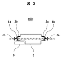
- FIG. 3 is a sectional view of the counterweight along the line AA in FIG.
- the counterweight 1 includes a counterweight frame 2, a weight 3, a pulley on the weight 400, guide devices 5a, 5b, 5c, and 5d, and oil supply devices 6a and 6b.
- the counterweight frame 2 has a pair of vertical frames 2a and 2b (disposed on both the left and right sides in FIG. 1) opposed to each other with a space therebetween, and a lower plate 2c that connects the lower ends of the vertical frames 2a and 2b. And it is comprised from the upper side board 2d which connects the upper end part of the vertical frames 2a and 2b.
- each of the vertical frames 2a and 2b has a U-shaped cross-sectional shape, is arranged so that the opening sides face each other, and the opposite opening side faces the guide rails 7a and 7b, respectively. It has become.
- the lower plate 2c is fixed to the lower part of the vertical frames 2a and 2b with bolts at both ends so as to receive the load of a plurality of weights 3 loaded thereon. Further, when the weight 3 arranged at the uppermost position is pressed downward by the weight presses 10a and 10b, the weight 3 as a whole is pressed against the lower side plate 2c, so that there is no backlash. Moreover, the receiving part 12 received by the buffering device (illustration omitted) installed in the bottom part of the hoistway is attached to the lower part of the lower side board 2c.
- Both ends of the upper plate 2d are fixed to the upper portions of the vertical frames 2a and 2b by bolts, and a weight upper pulley 400 is rotatably attached to the upper surface via a bracket 8.
- a main rope (not shown) is wound around the weight upper pulley 400, and the counterweight 100 is suspended by the main rope via the weight upper pulley 400.
- the weight upper pulley 400 is placed on the upper plate 2d. That is, the lower end of the weight upper pulley 400 is located above the upper surface of the weight 3 disposed at the uppermost position. Since the weight upper pulley 400 is placed on the upper plate 2d, the maintenance of the weight upper pulley 400 is facilitated.
- Guide devices 5 a, 5 b, 5 c and 5 d are arranged near the four corners of the counterweight frame 2. That is, the guide device 5a is the upper end of the vertical frame 2a, the guide device 5b is the lower end of the vertical frame 2a, the guide device 5c is the upper end of the vertical frame 2b, and the guide device 5d is the lower end of the vertical frame 2b.
- the guide devices 5a and 5b are attached to the guide rail 7a, and the guide devices 5c and 5d are in sliding contact with the guide rail 7b, respectively, to guide the lifting and lowering of the counterweight 1.
- the oil supply devices 6a and 6b are attached to the upper portions of the vertical frames 2a and 2b, that is, at positions close to the guide devices 5a and 5c.
- the oil supply devices 6a and 6b are attached to inverted L-shaped attachment members 11a and 11b attached to the upper portions of the vertical frames 2a and 2b, respectively.
- Each of the oil supply devices 6a and 6b has a tank for storing the lubricating oil, and has a structure for slowly supplying the lubricating oil from these tanks.
- the oil supply devices 6a and 6b apply lubricant to the guide rails 7a and 7b, respectively, and supply the lubricant between the guide devices 5a, 5b, 5c, and 5d and the guide rails 7a and 7b.
- the weights 3 stacked on the lower plate 2c have different shapes as shown in FIG. That is, the weight shape seen from the upper surface (horizontal plane) is atypical.
- the irregular shape of the weight means an asymmetric shape in the present embodiment. In other words, when the weight shape is different, it can be said that the center of gravity position of the weight viewed from the top surface is shifted from the center of gravity position of the region formed by the vertical frames 2a and 2b when viewed from the top surface.
- the weight 3 is fitted to the vertical frames 2a and 2b having U-shaped cross-sections at both ends in order to reduce the vertical frame of the counterweight frame and to efficiently use the space.
- the width is narrow so that they can be combined, and the central portion is wider than the width of the vertical frame.
- it is required to make this weight different. For example, if the space of the elevator apparatus is to be saved, the guide rails 7a and 7b have to be installed close to the wall side (upper side in FIG. 3). For this reason, the weight 3 has to be arranged so that both ends are deviated from the central portion. Therefore, the weight 3 is formed so that the wide central portion is located closer to the car side (the lower side in FIG.
- the center line of the weight 3 (the two-dot chain line in FIG. 3; the center of gravity is located on the line) is the center line of the area formed by the vertical frames 2a and 2b (the one-dot chain line in FIG. 3; the guide rail 7a, 7b coincides with the line connecting 7b and the center of gravity is located on the line.
- the weight of the hoistway device 9 as viewed from the top surface in relation to the arrangement of the hoistway device 9 (relationship with the position of the rope end, relation with the position of the speed governor when placed on the speed governor).
- the weight 3 is formed by cutting out a part of 3.
- the weight 3 has an asymmetrical shape (asymmetrical shape in the drawing of FIG. 3) when viewed from the length direction.
- the influence of the eccentricity of the center of gravity of the counterweight increases, and a large reaction force may act on the guide device.
- the elevator apparatus uses an unusual weight 3 and is devised to reduce the reaction force to the guide apparatuses 5a to 5d.
- the vertical frames 2a and 2b are extended by an extension dimension H1 within the limit of the counterweight, and the distance between the guide devices 5a and 5c on the upper end side and the guide devices 5b and 5d on the lower end side is extended.
- H2 is set large.
- Within the counterweight height limit is within the overhead dimensions of the counterweight 100 that is predetermined as the specifications of the elevator apparatus.
- the vertical frame 2a is originally provided so that the upper ends of the vertical frames 2a and 2b do not protrude from the upper surface of the upper plate 2d.
- 2b is preferably substantially the same as the height of the upper surface of the upper plate 2d.
- the guide devices 5a and 5c on the upper end side and the guide devices 5b and 5d on the lower end side from the new point of view that the reaction force to the guide devices 5a to 5d caused by the irregular weight 3 is reduced.
- the vertical frames 2a and 2b are intentionally extended upward in order to set a large distance dimension H2.
- the upper pulley 400 is installed on the upper surface of the upper plate 2d.
- the overhead dimension H0 of the counterweight 100 which is predetermined as the specifications of the elevator apparatus, is the height dimension from the lower end of the vertical frames 2a, 2b to the upper end of the bracket 8 that fixes the weight upper pulley 400.
- the vertical frames 2a and 2b It is allowed to extend upward beyond the upper surface of the upper plate 2d.
- the height dimension from the lower end of the vertical frames 2a and 2b to the upper end of the oil supply devices 6a and 6b is the overhead dimension.
- the vertical frames 2a and 2b are extended upward beyond the upper surface of the upper plate 2d within a range not exceeding. In other words, in this embodiment, the vertical frames 2a and 2b are extended by effectively using the existing space in the vertical direction.
- the reaction force received by the guide device varies depending on the degree of eccentricity of the center of gravity of the weight 3. If the degree of eccentricity of the center of gravity is large, it is desirable to extend the vertical frames 2a and 2b as much as possible. That is, as shown in FIG. 1, the upper ends of the oil supply devices 6a and 6b attached to the upper portions of the vertical frames 2a and 2b are substantially at the same level as the upper end of the bracket 8 that fixes the weight upper pulley 400 (the counterweight height limit).
- the vertical frames 2a and 2b are extended upward by an extension dimension H1 so that the upper ends of the oil supply devices 6a and 6b are within the upper limit of the counterweight, that is, within the overhead dimension.
- the vicinity of the counterweight height limit is a case where the upper end of the oil supply devices 6a, 6b is at the same level as the upper end of the bracket 8 and is extended by at least 90%. means. Further, in order to sufficiently obtain the effect of reducing the reaction force received by the guide device, the vertical frames 2a and 2b are extended by 100% when the upper ends of the oil supply devices 6a and 6b are at the same level as the upper end of the bracket 8. In this case, it is desirable to extend it by about 50%.
- the shape of the weight 3 of the counterweight 100 is atypical because of the arrangement of the hoistway device 9 and the like.
- the center of gravity of the counterweight 100 is decentered. Therefore, it is compared with the guide devices 5a to 5c arranged near the four corners of the counterweight 100.
- Large reaction force acts.
- the vertical frames 2a and 2b of the present embodiment are extended upward from the upper plate 2d by the extension dimension H1, and the guide devices 5a and 5c on the upper end side and the guide devices 5b and 5d on the lower end side are extended. Is set large. Accordingly, the reaction force acting on the guide devices 5a to 5c can be reduced, and thereby the life of the guide devices 5a to 5d can be extended.
- the vertical frames 2a and 2b are extended within the counterweight height limit, but the vertical frames 2a and 2b are extended by effectively using the existing space in the vertical direction. It is not necessary to change the overall height of the counterweight 100. Thus, the reaction force to the guide devices 5a to 5d can be reduced without affecting other devices and installation conditions.
- this invention is not limited to the above-mentioned Example, Various modifications are included.
- the above-described embodiments have been described in detail for easy understanding of the present invention, and are not necessarily limited to those having all the configurations described.
- a part of the configuration of one embodiment can be replaced with the configuration of another embodiment, and the configuration of another embodiment can be added to the configuration of one embodiment.
- 2 ... counterweight frame, 2a, 2b ... vertical frame, 2c ... lower plate, 2d ... upper plate, 3 ... weight, 5a-5d ... guide device, 6a, 6b ... Refueling device, 7a, 7b ... Guide rail (balanced weight guide rail), 8 ... Bracket, 9 ... Hoistway equipment, 10a, 10b ... Weight presser, 11a, 11b ... Mounting member, 12 ... receiving part, 100 ... counterweight, 200 ... riding car, 300 ... hoisting machine, 400 ... pulley on weight, 500 ... main rope.
Landscapes
- Engineering & Computer Science (AREA)
- Civil Engineering (AREA)
- Mechanical Engineering (AREA)
- Structural Engineering (AREA)
- Cage And Drive Apparatuses For Elevators (AREA)
- Lift-Guide Devices, And Elevator Ropes And Cables (AREA)
Abstract
Priority Applications (4)
| Application Number | Priority Date | Filing Date | Title |
|---|---|---|---|
| CN201680049441.8A CN108349700B (zh) | 2016-11-25 | 2016-11-25 | 电梯装置的平衡重以及电梯装置 |
| KR1020187005410A KR20180079287A (ko) | 2016-11-25 | 2016-11-25 | 엘리베이터 장치의 균형추 및 엘리베이터 장치 |
| JP2018506230A JP6452888B2 (ja) | 2016-11-25 | 2016-11-25 | エレベータ装置の釣合いおもり及びエレベータ装置 |
| PCT/JP2016/084923 WO2018096645A1 (fr) | 2016-11-25 | 2016-11-25 | Contrepoids pour dispositif d'ascenseur, et dispositif d'ascenseur |
Applications Claiming Priority (1)
| Application Number | Priority Date | Filing Date | Title |
|---|---|---|---|
| PCT/JP2016/084923 WO2018096645A1 (fr) | 2016-11-25 | 2016-11-25 | Contrepoids pour dispositif d'ascenseur, et dispositif d'ascenseur |
Publications (1)
| Publication Number | Publication Date |
|---|---|
| WO2018096645A1 true WO2018096645A1 (fr) | 2018-05-31 |
Family
ID=62195895
Family Applications (1)
| Application Number | Title | Priority Date | Filing Date |
|---|---|---|---|
| PCT/JP2016/084923 Ceased WO2018096645A1 (fr) | 2016-11-25 | 2016-11-25 | Contrepoids pour dispositif d'ascenseur, et dispositif d'ascenseur |
Country Status (4)
| Country | Link |
|---|---|
| JP (1) | JP6452888B2 (fr) |
| KR (1) | KR20180079287A (fr) |
| CN (1) | CN108349700B (fr) |
| WO (1) | WO2018096645A1 (fr) |
Cited By (3)
| Publication number | Priority date | Publication date | Assignee | Title |
|---|---|---|---|---|
| WO2020127303A1 (fr) * | 2018-12-20 | 2020-06-25 | Inventio Ag | Contrepoids asymétrique pour une installation d'ascenseur et installation d'ascenseur équipée de celui-ci |
| CN111689354A (zh) * | 2020-07-21 | 2020-09-22 | 杭州奥立达电梯有限公司 | 高曳引比条件下超大载重货梯用对重装置 |
| CN115159318A (zh) * | 2022-07-06 | 2022-10-11 | 三菱电机上海机电电梯有限公司 | 一种提高对重安装高度的对重框及其安装方法 |
Citations (6)
| Publication number | Priority date | Publication date | Assignee | Title |
|---|---|---|---|---|
| JPS4921844A (fr) * | 1972-06-23 | 1974-02-26 | ||
| JPS5954471U (ja) * | 1982-09-30 | 1984-04-10 | 三菱電機株式会社 | エレベ−タのつり合いおもり用吊り枠 |
| JPS5980363U (ja) * | 1982-11-22 | 1984-05-30 | 三菱電機株式会社 | エレベ−タの吊車取付装置 |
| JPH07223788A (ja) * | 1994-02-03 | 1995-08-22 | Otis Elevator Co | エレベーターのカウンターウェイト |
| WO2011018838A1 (fr) * | 2009-08-11 | 2011-02-17 | 三菱電機株式会社 | Dispositif d'ascenseur |
| JP2012121682A (ja) * | 2010-12-08 | 2012-06-28 | Hitachi Ltd | エレベータ装置 |
Family Cites Families (3)
| Publication number | Priority date | Publication date | Assignee | Title |
|---|---|---|---|---|
| JP2006290496A (ja) * | 2005-04-07 | 2006-10-26 | Mitsubishi Electric Corp | エレベータの釣合い重り装置 |
| CN202186813U (zh) * | 2011-07-27 | 2012-04-11 | 浙江诺比克电梯有限公司 | 电梯对重装置 |
| CN104709797B (zh) * | 2015-03-12 | 2018-10-26 | 日立电梯(中国)有限公司 | 一种电梯平衡对重 |
-
2016
- 2016-11-25 JP JP2018506230A patent/JP6452888B2/ja active Active
- 2016-11-25 KR KR1020187005410A patent/KR20180079287A/ko not_active Ceased
- 2016-11-25 WO PCT/JP2016/084923 patent/WO2018096645A1/fr not_active Ceased
- 2016-11-25 CN CN201680049441.8A patent/CN108349700B/zh active Active
Patent Citations (6)
| Publication number | Priority date | Publication date | Assignee | Title |
|---|---|---|---|---|
| JPS4921844A (fr) * | 1972-06-23 | 1974-02-26 | ||
| JPS5954471U (ja) * | 1982-09-30 | 1984-04-10 | 三菱電機株式会社 | エレベ−タのつり合いおもり用吊り枠 |
| JPS5980363U (ja) * | 1982-11-22 | 1984-05-30 | 三菱電機株式会社 | エレベ−タの吊車取付装置 |
| JPH07223788A (ja) * | 1994-02-03 | 1995-08-22 | Otis Elevator Co | エレベーターのカウンターウェイト |
| WO2011018838A1 (fr) * | 2009-08-11 | 2011-02-17 | 三菱電機株式会社 | Dispositif d'ascenseur |
| JP2012121682A (ja) * | 2010-12-08 | 2012-06-28 | Hitachi Ltd | エレベータ装置 |
Cited By (5)
| Publication number | Priority date | Publication date | Assignee | Title |
|---|---|---|---|---|
| WO2020127303A1 (fr) * | 2018-12-20 | 2020-06-25 | Inventio Ag | Contrepoids asymétrique pour une installation d'ascenseur et installation d'ascenseur équipée de celui-ci |
| US20220041407A1 (en) * | 2018-12-20 | 2022-02-10 | Inventio Ag | Counterweight for an elevator system and elevator system equipped with the counterweight |
| US11814263B2 (en) | 2018-12-20 | 2023-11-14 | Inventio Ag | Counterweight for an elevator system and elevator system equipped with the counterweight |
| CN111689354A (zh) * | 2020-07-21 | 2020-09-22 | 杭州奥立达电梯有限公司 | 高曳引比条件下超大载重货梯用对重装置 |
| CN115159318A (zh) * | 2022-07-06 | 2022-10-11 | 三菱电机上海机电电梯有限公司 | 一种提高对重安装高度的对重框及其安装方法 |
Also Published As
| Publication number | Publication date |
|---|---|
| CN108349700A (zh) | 2018-07-31 |
| KR20180079287A (ko) | 2018-07-10 |
| JPWO2018096645A1 (ja) | 2018-11-22 |
| CN108349700B (zh) | 2019-09-27 |
| JP6452888B2 (ja) | 2019-01-16 |
Similar Documents
| Publication | Publication Date | Title |
|---|---|---|
| CN103796942B (zh) | 用于电梯的悬挂配置和导引靴配置 | |
| CN102115005B (zh) | 双层电梯 | |
| US20170362063A1 (en) | Elevator system roping arrangement | |
| CN205855679U (zh) | 一种电梯对重补偿装置 | |
| JP6452888B2 (ja) | エレベータ装置の釣合いおもり及びエレベータ装置 | |
| CN106061884A (zh) | 用于钢绳提升机的低结构台车 | |
| KR101162240B1 (ko) | 엘리베이터 장치 | |
| JP2004142927A (ja) | エレベータ装置 | |
| KR101690856B1 (ko) | 엘리베이터 장치 | |
| JP6738964B2 (ja) | エレベーター | |
| CN104649100B (zh) | 电梯补偿绳张紧装置 | |
| CN213202043U (zh) | 一种具有循环补偿链的电梯 | |
| JP2015168533A (ja) | エレベータ装置 | |
| JP5940713B1 (ja) | エレベータのコンペンシーブ支持構造体 | |
| JP7064620B2 (ja) | 工事用エレベーター装置 | |
| JP2006016184A (ja) | Cwtレスエレベータ装置 | |
| KR101437800B1 (ko) | 엘리베이터 장치 | |
| JP2015013713A (ja) | コンペンチェーン装置及びエレベータ装置 | |
| JP4946034B2 (ja) | エレベータのコンペンチェーンガイド装置 | |
| CN103596869B (zh) | 电梯 | |
| CN211225939U (zh) | 涨紧轮机构及升降装置 | |
| KR20040068178A (ko) | 엘리베이터 장치 | |
| CN105858414A (zh) | 一种无机房电梯 | |
| JP2008044744A (ja) | エレベータ装置 | |
| JP2006290496A (ja) | エレベータの釣合い重り装置 |
Legal Events
| Date | Code | Title | Description |
|---|---|---|---|
| ENP | Entry into the national phase |
Ref document number: 2018506230 Country of ref document: JP Kind code of ref document: A |
|
| ENP | Entry into the national phase |
Ref document number: 20187005410 Country of ref document: KR Kind code of ref document: A |
|
| 121 | Ep: the epo has been informed by wipo that ep was designated in this application |
Ref document number: 16922566 Country of ref document: EP Kind code of ref document: A1 |
|
| NENP | Non-entry into the national phase |
Ref country code: DE |
|
| 122 | Ep: pct application non-entry in european phase |
Ref document number: 16922566 Country of ref document: EP Kind code of ref document: A1 |