WO2018097210A1 - Procédé de production d'une céramique poreuse, et céramique poreuse - Google Patents
Procédé de production d'une céramique poreuse, et céramique poreuse Download PDFInfo
- Publication number
- WO2018097210A1 WO2018097210A1 PCT/JP2017/042102 JP2017042102W WO2018097210A1 WO 2018097210 A1 WO2018097210 A1 WO 2018097210A1 JP 2017042102 W JP2017042102 W JP 2017042102W WO 2018097210 A1 WO2018097210 A1 WO 2018097210A1
- Authority
- WO
- WIPO (PCT)
- Prior art keywords
- ceramic
- combustion
- pores
- porous
- kneading
- Prior art date
- Legal status (The legal status is an assumption and is not a legal conclusion. Google has not performed a legal analysis and makes no representation as to the accuracy of the status listed.)
- Ceased
Links
Images




Classifications
-
- A—HUMAN NECESSITIES
- A61—MEDICAL OR VETERINARY SCIENCE; HYGIENE
- A61K—PREPARATIONS FOR MEDICAL, DENTAL OR TOILETRY PURPOSES
- A61K47/00—Medicinal preparations characterised by the non-active ingredients used, e.g. carriers or inert additives; Targeting or modifying agents chemically bound to the active ingredient
- A61K47/02—Inorganic compounds
-
- A—HUMAN NECESSITIES
- A61—MEDICAL OR VETERINARY SCIENCE; HYGIENE
- A61L—METHODS OR APPARATUS FOR STERILISING MATERIALS OR OBJECTS IN GENERAL; DISINFECTION, STERILISATION OR DEODORISATION OF AIR; CHEMICAL ASPECTS OF BANDAGES, DRESSINGS, ABSORBENT PADS OR SURGICAL ARTICLES; MATERIALS FOR BANDAGES, DRESSINGS, ABSORBENT PADS OR SURGICAL ARTICLES
- A61L27/00—Materials for grafts or prostheses or for coating grafts or prostheses
- A61L27/02—Inorganic materials
- A61L27/10—Ceramics or glasses
-
- C—CHEMISTRY; METALLURGY
- C04—CEMENTS; CONCRETE; ARTIFICIAL STONE; CERAMICS; REFRACTORIES
- C04B—LIME, MAGNESIA; SLAG; CEMENTS; COMPOSITIONS THEREOF, e.g. MORTARS, CONCRETE OR LIKE BUILDING MATERIALS; ARTIFICIAL STONE; CERAMICS; REFRACTORIES; TREATMENT OF NATURAL STONE
- C04B38/00—Porous mortars, concrete, artificial stone or ceramic ware; Preparation thereof
- C04B38/06—Porous mortars, concrete, artificial stone or ceramic ware; Preparation thereof by burning-out added substances by burning natural expanding materials or by sublimating or melting out added substances
-
- C—CHEMISTRY; METALLURGY
- C04—CEMENTS; CONCRETE; ARTIFICIAL STONE; CERAMICS; REFRACTORIES
- C04B—LIME, MAGNESIA; SLAG; CEMENTS; COMPOSITIONS THEREOF, e.g. MORTARS, CONCRETE OR LIKE BUILDING MATERIALS; ARTIFICIAL STONE; CERAMICS; REFRACTORIES; TREATMENT OF NATURAL STONE
- C04B41/00—After-treatment of mortars, concrete, artificial stone or ceramics; Treatment of natural stone
- C04B41/80—After-treatment of mortars, concrete, artificial stone or ceramics; Treatment of natural stone of only ceramics
- C04B41/81—Coating or impregnation
- C04B41/85—Coating or impregnation with inorganic materials
Definitions
- the present invention relates to porous ceramics, particularly porous ceramics having pores.
- porous ceramics As a method for producing porous ceramics, a method of making a porous material by adding a large amount of a pore-forming agent such as a deflocculant or resin beads to ceramic powder and removing it by oxidation is generally used. However, even if the is removed, there is a problem in that it is difficult to obtain continuous open pores because the holes exist in isolation.
- a method of attaching ceramic sludge to a flexible polyurethane foam without cell membrane and sintering it Patent Document 1 or adding a ceramic raw material and a deflocculant in an aqueous solution, followed by adding a cell material and sintering.
- Patent Document 2 A method of performing this method has also been proposed. However, these production methods have a problem that porous ceramics having submicron pores or nano-sized pores cannot be obtained.
- a preparation step of preparing a combustion vaporization material and a ceramic material, a kneading step of kneading the prepared combustion vaporization material and a ceramic material to obtain an intermediate there is provided a method for producing porous ceramics, comprising: firing a body or / and an intermediate derivative to obtain a ceramic having a large number of pores by burning and vaporizing the combustion vaporized material.
- the combustion vaporization material has a maximum diameter of submicron.
- a third invention having a drug impregnation step for impregnating the porous ceramic obtained in the firing step with a drug.
- an intermediate for producing porous ceramics in which a combustion vaporizing material is uniformly dispersed in a ceramic raw material is provided.
- the combustion vaporized material is uniformly in the ceramic raw material obtained by blocking the intermediate of the fourth invention, drying the blocked one, and crushing and grinding the dried one.
- An intermediate derivative for producing a dispersed porous ceramic is provided.
- a porous ceramic having pores through which a combustion vaporized material filled by firing can be discharged to the outside even when the pores are filled with a combustion vaporized material.
- the seventh invention provides the seventh invention, wherein the pores include submicron pores.
- FIG. 3 is a flowchart showing a method for manufacturing the porous ceramic according to the first embodiment.
- FIG. 3 is a flowchart showing a method for manufacturing the porous ceramic according to the first embodiment.
- the present embodiment is a method for producing porous ceramics, the feature of which is that ceramics are produced by mixing a combustion vaporized material with ceramic raw materials in advance and kneading (also referred to as “kneading”, hereinafter the same). is there. ⁇ Configuration>
- FIG. 1 is a flow diagram showing a method for producing a porous ceramic according to the present embodiment.
- the configuration of this embodiment includes a preparation step (S0101), a kneading step (S0102), and a firing step (S0103).
- FIG. 2 is another flowchart showing the method for manufacturing the porous ceramics of the present embodiment.
- This embodiment is based on FIG. 1, and impregnates the chemical into the porous ceramics obtained by the preparation step (S0201), the kneading step (S0202) and the firing step (S0203) (S0204: chemical impregnation step),
- S0201 preparation step
- S0202 kneading step
- S0203 firing step
- S0204 chemical impregnation step
- the preparation step is a step of preparing a combustion vaporization material and a ceramic material.
- Combustion vaporization materials correspond to cellulose, carbon materials, and organic compounds, and are materials that are solid. Accordingly, liquid and gel materials are not included in the combustion vaporization material. However, a material that appears to be macroscopically liquid or gelled by mixing a solid material with a liquid is a solid combustion vaporized material as referred to in the present invention.
- the essential feature of the aspect of the present invention which has pores of submicron to several tens of nanometers and the pores penetrate the inside of the ceramic block, depends on the shape and size of the combustion vaporization material. In the point, the porous property finally formed in the ceramic material is obtained. That is, the holes provided on the surface or inner surface of the ceramic material are controlled by the shape and size of the combustion vaporized material. Therefore, in the preparation step, preparation is performed assuming the size of the holes to be provided in the target porous ceramic, the amount of holes, the density of the holes, and the like.
- the shape of the ceramic raw material must be designed in advance to control the properties of the final porous ceramic.
- the design is performed according to the particle size, particle size distribution, and raw material type.
- the preparation stage after mixing the ceramic raw material and the combustion vaporizing material, there may be a step of further miniaturizing with a ball mill or the like. This is preferable in order that the ceramic raw material grains and the combustion vaporized material are mixed while being refined and both are uniformly dispersed in the next kneading step. ⁇ Kneading step>
- the prepared combustion vaporization material and the prepared ceramic material are kneaded.
- the kneading may be performed by adding a liquid, for example, but the pH of the liquid may be adjusted to be alkaline or acidic as necessary. This is adjusted depending on the ceramic raw material and the type of combustion vaporized material.
- the liquid may be kneaded using an organic liquid such as water or alcohol. Also, water and an organic liquid such as alcohol may be used in combination. After kneading, liquids such as water and alcohol and components used for kneading are excluded by drying.
- the drying rate is a control target parameter. This is because the pressure and amount of the gas generated from the combustion vaporized material at the time of firing or the previous ceramic block after kneading and drying change depending on the degree of drying. The pressure of the gas and the amount of the gas influence the size, the amount of the hole, the density of the hole, and the degree of penetration of the hole in the finally obtained porous ceramic.
- the surfactant is difficult to disperse in the liquid. May be shared. However, care should be taken because the surfactant is also a factor that affects the firing.
- a preheating substep may be employed to eliminate the surfactant.
- the kneading step may be performed using a tool such as a normal mixer, propeller stirrer, kneader or the like, but kneading becomes difficult when the material has a very small size. Therefore, it is conceivable to apply ultrasonic waves or high-frequency electromagnetic fields to the kneading vessel.
- the high-frequency electromagnetic field can polarize fine particles of the ceramic raw material depending on the controlled state, and is easily mixed with water. Moreover, the same effect may be produced also about a combustion vaporization raw material.
- an intermediate can be obtained.
- the intermediate is in a state in which the combustion vaporized material is uniformly dispersed in the ceramic raw material by the kneading step.
- the intermediate may be in the form of powder immediately after kneading, or in the form of liquid or slurry, or may be in the form of a block obtained by drying the liquid or slurry.
- the uniformly dispersed state is a state in which the combustion vaporized composition has entered between the ceramic raw material, and there is no bias in the amount and concentration of the combustion vaporized composition existing around the ceramic raw material. State.
- the kneading step may include a sub-step in which a liquid or slurry-like material is dried and once made into a block shape is pulverized again and then kneaded again. That is, another intermediate derived from this intermediate is obtained from the block of the intermediate generated by kneading. This other intermediate is referred to herein as an intermediate derivative.
- the firing step has two significances. One is the significance that the fine particles of the ceramic raw material are locally melted and welded to grow ceramic grains, and that the pores forming the porous are created. Therefore, in the firing step, the above two phenomena proceed simultaneously.
- the combustion temperature of the combustion vaporized material is lower than the local melting temperature of the ceramic. Accordingly, if the work vapor (vapor) is burned but the workpiece (intermediate) is retained for a long time at a temperature at which the ceramic grains do not grow, it becomes a non-porous ceramic.
- a chemical impregnation step can also be performed after the kneading step.
- the chemical impregnation step is a step of impregnating the chemical into the porous ceramic obtained in the firing step.
- medical agent with which a porous ceramic is impregnated is not specifically limited, For example, a catalyst, protein, a cell, a chemical
- the required pore size, the amount of pores, the density of the pores, and the degree of penetration of the pores are different, but the present invention is submicron finally formed in the ceramic material depending on the shape and size of the combustion vaporization material.
- the method for impregnating the drug is not particularly limited, and examples thereof include an impregnation method, an ion exchange method, a vapor deposition method, and a spray drying method. If the gas, liquid, etc. are not sufficiently infiltrated into the pores due to the surface tension etc. of the impregnated liquid, etc., make the high pressure side and the low pressure side with the ceramic as a partition, and infiltrate the gas, liquid, etc. using the pressure difference .
- combustion vaporization material is a material that burns and vaporizes in the firing step.
- the combustion vaporization material is not particularly limited, but is a material that burns and vaporizes in the firing step and disappears from the fired porous ceramics.
- FIG. 3 is a diagram for explaining the maximum diameter when the combustion vaporization material is substantially cylindrical.
- the maximum diameter in the case of an elongated shape such as a substantially cylinder is not the length in the longitudinal direction, but the maximum value (D1 in the drawing) corresponding to the diameter of the cylinder is the maximum diameter.
- the combustion vaporization material of the present invention preferably has a maximum diameter of submicron.
- the combustion vaporization material having a maximum diameter of submicron is not particularly limited.
- the submicron diameter is about several tens of nanometers.
- the porous ceramics can be obtained in such a manner that the pores pass through the inside of the ceramic block.
- Carbon fiber is a fiber composed of 90% or more by mass of carbon, and is a fiber made by carbonizing polyacrylonitrile fiber or pitch fiber at a high temperature. Carbon fiber is characterized by a low heat shrinkage rate, and when carbon fiber or a material containing carbon fiber pulverized material is used as a combustion vaporized fine material. Since expansion and contraction of the combustion vaporized fine material in the firing step are unlikely to occur, it is preferable because the occurrence of cracks and cracks in the fired body is suppressed and pores corresponding to the size of the carbon fiber or the carbon fiber crushed material are easily formed.
- Cellulose is a main component of plant fiber and is a polysaccharide insoluble in water.
- the combustion vaporizing material containing cellulose it is particularly preferable to use a material containing cellulose nanofibers.
- Cellulose nanofiber refers to fine cellulose fiber obtained by defibrating pulp (pulp fiber), which is a plant material, and generally includes cellulose fine fiber having a fiber width of nanosize (1 nm to 1000 nm). Refers to fiber.
- the water retention of cellulose nanofibers is preferably 250% or more and 500% or less, for example.
- the water retention (%) of the cellulose nanofibers is JAPAN TAPPI No. 26 is measured.
- the cellulose nanofiber preferably has only one peak in a pseudo particle size distribution curve measured by a laser diffraction method in an aqueous dispersion state.
- a particle size (mode) of the cellulose nanofiber which becomes this peak 5 micrometers or more and 50 micrometers or less are preferable, for example.
- the “pseudo particle size distribution curve” means a curve indicating a volume-based particle size distribution measured using a particle size distribution measuring apparatus.
- cellulose Since cellulose is derived from plants, the use of cellulose nanofibers as a material for combustion and vaporization is more effective for a low-carbon society than when chemically synthesized materials such as polyvinyl alcohol and ammonium polyacrylate are used. There is an advantage of being able to contribute. In addition, there is an advantage that it is an environmentally friendly material because it does not discharge harmful substances such as nitrogen oxides even if it is vaporized by combustion. Cellulose is also characterized by a low thermal shrinkage similar to carbon fibers, and is also superior in that it does not easily cause expansion and contraction of the combustion vaporized fine material in the firing step, like carbon fibers. (Ceramic raw material)
- the “ceramic raw material” is not particularly limited, but is known as a porous ceramic material, for example, alumina, aluminum silicate, cordierite, silica, zirconia, silicon carbide, silicon nitride, mullite, magnesia, nitriding Examples thereof include, but are not limited to, aluminum, boron nitride, and calcium phosphate. These raw materials can be used alone, but two or more ceramic raw materials can also be mixed and used.
- the ceramic raw material it is preferable to use calcium phosphate such as ⁇ -tricalcium phosphate or hydroxyapatite.
- Porous ceramic materials such as ⁇ -tricalcium phosphate and hydroxyapatite, are used as granules or molded bodies as bone substitute materials or artificial bone implants. Attempts have been made to promote replacement with autologous bone and to improve the bioabsorbability of bone substitutes. In general, it is said that cells are micron-sized, proteins are sub-micron-sized, and drugs are easily fixed to nano-sized pores. According to the present invention, pore size, pore volume, pore density, pore penetration This is because it is possible to obtain porous ceramics with a controlled degree and to immobilize proteins and the like.
- ⁇ -tricalcium phosphate, alumina, or hydroxyapatite was used as a ceramic raw material.
- cellulose was used as the combustion vaporizing material.
- ⁇ -tricalcium phosphate and cellulose were prepared as follows. (1) ⁇ -tricalcium phosphate (preparation of ⁇ -tricalcium phosphate)
- ⁇ -tricalcium phosphate As raw materials for ⁇ -tricalcium phosphate, 301.78 g of calcium carbonate and 266.79 g of ammonium dihydrogen phosphate were prepared, and pulverized and mixed in a ball mill for 48 hours using 2 liters of ethanol as a solvent. Ethanol was separated from the liquid mixture using a filtration device and / or an evaporator to obtain a slurry. The slurry was divided into two alumina sheaths and subjected to pre-sintering A to obtain pre-sintered body A.
- the pre-sintering conditions were as follows: air temperature rate of 3 ° C./min, firing temperature of 900 ° C., holding time of 12 hours, and temperature drop rate of 3 ° C./min to room temperature.
- the crystal phase of the obtained pre-fired product A had a ⁇ -tricalcium phosphate structure of 95% or more, but in order to make the crystal phase a ⁇ -tricalcium phosphate structure more reliably, two more times.
- Pre-sintering was performed. Specifically, the pre-fired body A was pulverized with a ball mill for 4 hours, then placed in an alumina sheath, and pre-sintered B was performed under the same conditions as pre-sintered A to obtain a pre-fired body B. The pre-sintered body B returned to room temperature was again pre-sintered C under the same conditions as pre-sintered A and B to obtain a pre-sintered body C.
- the powder of ⁇ -tricalcium phosphate having an average particle diameter of about 3 ⁇ m obtained by pulverizing the pre-fired product C with a ball mill or pulverizing with a mortar was used as a ceramic raw material. (Preparation of ⁇ -tricalcium phosphate with solid solution of silicon, sodium and magnesium)
- ⁇ -tricalcium phosphate in which silicon, sodium and magnesium are dissolved can be used as a ceramic raw material.
- sodium carbonate, magnesium oxide and silicon dioxide By adding sodium carbonate, magnesium oxide and silicon dioxide to the ⁇ -tricalcium phosphate starting material described above, a ⁇ -tricalcium phosphate powder in which 2.0 mol% of silicic acid was dissolved was similarly prepared. The obtained powder was used as a ceramic raw material.
- 446.34 g of calcium carbonate, 427.40 g of ammonium dihydrogen phosphate, 3.4722 g of sodium carbonate, 18.8463 g of magnesium oxide, and 3.9332 g of silicon dioxide were used as starting materials.
- hydroxyapatite high-purity calcium phosphate, spherical HAP (3Ca 3 (PO 4 ) 2 ⁇ Ca (OH) 2 ) from Taihei Chemical Industrial Co., Ltd. having an average particle size of 15 to 20 ⁇ m was used.
- HAP spherical HAP
- an aqueous cellulose nanofiber solution having a particle size (mode) of 21 ⁇ m, a water retention of 389%, and a concentration of 1.7 wt% was used as the cellulose.
- the cellulose nanofiber aqueous solution used contains cellulose fine fibers of several tens of nm.
- the water retention (%) of cellulose was determined by JAPAN TAPPI No. Measured according to No. 26.
- the volume-based particle size distribution measured using a particle size distribution measuring device was measured, and the mode value of the obtained pseudo particle size distribution curve was taken as the particle size. (Method for evaluating porous ceramics)
- the method for evaluating the produced porous ceramic will be described first.
- the pore distribution was measured with a mercury porosimeter, and the microstructure was observed with a scanning electron microscope (SEM).
- SEM scanning electron microscope
- the open porosity and closed porosity were calculated from volume, dry mass, water absorption mass and true specific gravity (document values).
- the volume was calculated by measuring the length and diameter of the obtained sintered body.
- the water absorption mass was measured by immersing the specimen in boiling water for 2 hours and then allowing it to cool in water.
- the intermediate after drying had a certain shape and strength and did not collapse even when cut out with a diamond cutter. It was also possible to drill holes with a drill.
- the dried intermediate body taken out of the Teflon (registered trademark) container was cut with a diamond cutter to form a substantially cubic shape of about 10 mm square. (Baking step)
- the molded body was fired to produce a porous ceramic. Firing was carried out under conditions of a temperature rising rate of 3 ° C./min, a calcining temperature of 1130 ° C., a holding time of 24 hours, a temperature lowering rate of 3 ° C./min to room temperature, and the atmosphere.
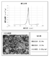
- FIG. 4 is a diagram showing the pore distribution, physical property values and microstructure of the obtained porous ceramic.
- the obtained porous ceramics was a dense body having a certain strength, the mode pore diameter was 2.79 ⁇ m, and pores were also observed in the vicinity of 90 to 110 nm. Moreover, it was confirmed from the SEM photograph showing the fine structure that it was porous and sintered.
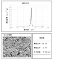
- FIG. 5 is a diagram showing the pore distribution, physical properties, and microstructure of the obtained porous ceramic.
- the obtained porous ceramics was a dense body having a certain strength, the mode pore diameter was 1.72 ⁇ m, and pores were observed at 30 to 70 nm. Moreover, it was confirmed from the SEM photograph showing the fine structure that it was porous and sintered.
- FIG. 6 is a diagram showing the pore distribution, physical properties, and microstructure of the obtained porous ceramic.
- the obtained porous ceramic was a dense body having a certain strength, the mode pore diameter was 1.03 ⁇ m, and pores were observed at 20 to 60 nm. Moreover, it was confirmed from the SEM photograph showing the fine structure that it was porous and sintered.
- Preparation step 50 g of cellulose nanofiber aqueous solution and 45 g of hydroxyapatite were prepared. (Kneading step) The mixture was stirred with a stirrer for 3 minutes, and 20 g of ion-exchanged water was further added.
- the state after kneading was pasty, and water did not separate into the surface layer. Drying at 65 ° C. for 1-2 days gave an intermediate.
- the intermediate after drying had a certain shape and strength and did not collapse even when cut out with a diamond cutter. It was also possible to drill holes with a drill.
- the resulting dried intermediate was pulverized with an alumina mortar, and relatively large particles were removed using a sieve covered with nylon mesh fibers to obtain an intermediate derivative.
- the intermediate derivative was subjected to uniaxial pressure molding at 98 MPa for 1 minute using a ⁇ 20 mm mold to prepare a molded body. (Baking step)
- the obtained molded body was fired under the same conditions as in Experiment 1 to produce porous ceramics.
- FIG. 7 is a diagram showing the pore distribution, physical property values, and microstructure of the obtained porous ceramic.
- the obtained porous ceramics was a dense body having a certain strength, the mode pore diameter was 0.15 ⁇ m, and pores were observed at 40 to 90 nm. Moreover, it was confirmed from the SEM photograph showing the fine structure that it was porous and sintered.
- Preparation step 50 g of cellulose nanofiber aqueous solution and 45 g of alumina were prepared.
- Kneading step The mixture was stirred for 3 minutes with a stirrer, and 20 g of ion-exchanged water was further added.
- Firing was carried out under conditions of a temperature rising rate of 3 ° C./min, a calcining temperature of 1600 ° C., a holding time of 24 hours, a temperature lowering rate of 3 ° C./min to room temperature, and atmospheric conditions.
- FIG. 8 is a diagram showing the pore distribution, physical property values, and microstructure of the obtained porous ceramic.
- the obtained porous ceramics was a dense body having a certain strength, the mode pore diameter was 0.42 ⁇ m, and pores were observed at 90 to 200 nm. Moreover, it was confirmed from the SEM photograph showing the fine structure that it was porous and sintered. ⁇ Effect>
- the obtained porous ceramics had nano-sized pores in addition to the peak of the most frequent pore diameter.
- a peptizer dispersant
- a binder a binder
- a lubricant of about 5 to 20 in terms of solid content
- ceramics are used. It is also excellent in that the effect of the dispersant and the binder is exhibited at a low concentration of about 2 in terms of solid content with respect to the raw material 100.
- the present embodiment is a porous ceramic, and its characteristic feature is that it has fine pores that can be discharged to the outside even when filled with the combustion vaporization material used in the production, and the fine pores are submicron diameter fine. It is in the point including a hole.
- This ceramic uses the ceramic as a partition to create a high-pressure side and a low-pressure side, and infiltrates the combustion vaporized material using a pressure difference. Then, by placing the infiltrated ceramics in the combustion vaporization material combustion atmosphere, all of the combustion vaporization material infiltrated inside is removed. This makes it possible to carry a combustion vaporized material having a large surface area per unit volume.
- This ceramic can be manufactured by the previously described embodiments. For example, it can be manufactured by a process such as Experiment 1 to Experiment 3.
- the porous ceramic according to the present embodiment has pores through which the combustion vaporized material filled by firing can be discharged to the outside even when the pores are filled with the combustion vaporized material. Contains pores.
- the combustion vaporization material corresponds to carbon or cellulose nanofiber.
Landscapes
- Chemical & Material Sciences (AREA)
- Health & Medical Sciences (AREA)
- Engineering & Computer Science (AREA)
- Ceramic Engineering (AREA)
- Inorganic Chemistry (AREA)
- General Health & Medical Sciences (AREA)
- Materials Engineering (AREA)
- Structural Engineering (AREA)
- Veterinary Medicine (AREA)
- Medicinal Chemistry (AREA)
- Organic Chemistry (AREA)
- Public Health (AREA)
- Epidemiology (AREA)
- Life Sciences & Earth Sciences (AREA)
- Animal Behavior & Ethology (AREA)
- Oral & Maxillofacial Surgery (AREA)
- Transplantation (AREA)
- Dermatology (AREA)
- Pharmacology & Pharmacy (AREA)
- Medicinal Preparation (AREA)
- Materials For Medical Uses (AREA)
- Compositions Of Oxide Ceramics (AREA)
- Porous Artificial Stone Or Porous Ceramic Products (AREA)
Abstract
Le problème décrit par la présente invention est de produire, d'une manière bien contrôlée, un article ayant des pores d'un diamètre submicronique à un diamètre de plusieurs dizaines de nanomètres, les pores pénétrant à l'intérieur d'un bloc céramique. La solution selon l'invention consiste à préparer un matériau vaporisable combustible et une matière première céramique, le matériau vaporisable combustible étant malaxé avec la matière première céramique à l'avance, et avec un intermédiaire et/ou un dérivé intermédiaire pour produire une céramique poreuse dans laquelle le matériau vaporisable combustible est uniformément dispersé dans la matière première céramique, après quoi le matériau vaporisable combustible est brûlé et vaporisé, et une céramique ayant une pluralité de pores est produite.
Applications Claiming Priority (2)
| Application Number | Priority Date | Filing Date | Title |
|---|---|---|---|
| JP2016229140A JP7016610B2 (ja) | 2016-11-25 | 2016-11-25 | 多孔質セラミックスの製造方法ならびに多孔質セラミックス |
| JP2016-229140 | 2016-11-25 |
Publications (1)
| Publication Number | Publication Date |
|---|---|
| WO2018097210A1 true WO2018097210A1 (fr) | 2018-05-31 |
Family
ID=62195902
Family Applications (1)
| Application Number | Title | Priority Date | Filing Date |
|---|---|---|---|
| PCT/JP2017/042102 Ceased WO2018097210A1 (fr) | 2016-11-25 | 2017-11-22 | Procédé de production d'une céramique poreuse, et céramique poreuse |
Country Status (2)
| Country | Link |
|---|---|
| JP (1) | JP7016610B2 (fr) |
| WO (1) | WO2018097210A1 (fr) |
Cited By (3)
| Publication number | Priority date | Publication date | Assignee | Title |
|---|---|---|---|---|
| CN113795474A (zh) * | 2019-06-04 | 2021-12-14 | 学校法人千叶工业大学 | 多孔质陶瓷和多孔质陶瓷的制造方法 |
| WO2022138906A1 (fr) * | 2020-12-25 | 2022-06-30 | 東亞合成株式会社 | Corps moulé inorganique et liant pour corps moulé inorganique |
| CN116217269A (zh) * | 2021-12-03 | 2023-06-06 | 深圳麦克韦尔科技有限公司 | 多孔陶瓷、多孔陶瓷内表面修饰用改性液及其制备方法和应用 |
Citations (6)
| Publication number | Priority date | Publication date | Assignee | Title |
|---|---|---|---|---|
| JPH02116684A (ja) * | 1988-10-21 | 1990-05-01 | Permelec Electrode Ltd | リン酸カルシウム化合物多孔質体の製造方法 |
| JPH08301672A (ja) * | 1995-05-01 | 1996-11-19 | Shin Etsu Chem Co Ltd | 多孔質焼結体用粉末の製造方法 |
| JPH10158075A (ja) * | 1996-11-25 | 1998-06-16 | Advance Co Ltd | セラミックスの製造方法 |
| WO2005091393A1 (fr) * | 2004-03-22 | 2005-09-29 | Japan Science And Technology Agency | Matériau thermoélectrique poreux et processus de production de celui-ci |
| JP2005263537A (ja) * | 2004-03-17 | 2005-09-29 | Rikogaku Shinkokai | 貫通孔を有するセラミックス多孔体の製造方法 |
| JP2016056460A (ja) * | 2014-09-05 | 2016-04-21 | 大王製紙株式会社 | セルロースナノファイバー、構造体、積層体及びセルロースナノファイバーの製造方法 |
Family Cites Families (6)
| Publication number | Priority date | Publication date | Assignee | Title |
|---|---|---|---|---|
| JPH06135778A (ja) * | 1991-07-18 | 1994-05-17 | Takeo Omi | 発泡陶器 |
| JPH05294751A (ja) * | 1992-04-10 | 1993-11-09 | Kaminishi Kagaku:Kk | 軽量タイルの製造方法 |
| JP3135110B2 (ja) * | 1995-11-29 | 2001-02-13 | 工業技術院長 | 多孔質セラミックス膜とその製造方法 |
| JP2007269622A (ja) * | 2006-03-06 | 2007-10-18 | Inax Corp | 軽量セラミックスの製造方法及びその原料 |
| JP2008007342A (ja) * | 2006-06-27 | 2008-01-17 | Toshiba Corp | 異方性多孔質セラミックス材料およびその製造方法 |
| CN101558025A (zh) * | 2006-12-11 | 2009-10-14 | 康宁股份有限公司 | α-氧化铝无机膜载体及其制备方法 |
-
2016
- 2016-11-25 JP JP2016229140A patent/JP7016610B2/ja active Active
-
2017
- 2017-11-22 WO PCT/JP2017/042102 patent/WO2018097210A1/fr not_active Ceased
Patent Citations (6)
| Publication number | Priority date | Publication date | Assignee | Title |
|---|---|---|---|---|
| JPH02116684A (ja) * | 1988-10-21 | 1990-05-01 | Permelec Electrode Ltd | リン酸カルシウム化合物多孔質体の製造方法 |
| JPH08301672A (ja) * | 1995-05-01 | 1996-11-19 | Shin Etsu Chem Co Ltd | 多孔質焼結体用粉末の製造方法 |
| JPH10158075A (ja) * | 1996-11-25 | 1998-06-16 | Advance Co Ltd | セラミックスの製造方法 |
| JP2005263537A (ja) * | 2004-03-17 | 2005-09-29 | Rikogaku Shinkokai | 貫通孔を有するセラミックス多孔体の製造方法 |
| WO2005091393A1 (fr) * | 2004-03-22 | 2005-09-29 | Japan Science And Technology Agency | Matériau thermoélectrique poreux et processus de production de celui-ci |
| JP2016056460A (ja) * | 2014-09-05 | 2016-04-21 | 大王製紙株式会社 | セルロースナノファイバー、構造体、積層体及びセルロースナノファイバーの製造方法 |
Cited By (4)
| Publication number | Priority date | Publication date | Assignee | Title |
|---|---|---|---|---|
| CN113795474A (zh) * | 2019-06-04 | 2021-12-14 | 学校法人千叶工业大学 | 多孔质陶瓷和多孔质陶瓷的制造方法 |
| CN113795474B (zh) * | 2019-06-04 | 2023-08-18 | 学校法人千叶工业大学 | 多孔质陶瓷和多孔质陶瓷的制造方法 |
| WO2022138906A1 (fr) * | 2020-12-25 | 2022-06-30 | 東亞合成株式会社 | Corps moulé inorganique et liant pour corps moulé inorganique |
| CN116217269A (zh) * | 2021-12-03 | 2023-06-06 | 深圳麦克韦尔科技有限公司 | 多孔陶瓷、多孔陶瓷内表面修饰用改性液及其制备方法和应用 |
Also Published As
| Publication number | Publication date |
|---|---|
| JP7016610B2 (ja) | 2022-02-07 |
| JP2018083742A (ja) | 2018-05-31 |
Similar Documents
| Publication | Publication Date | Title |
|---|---|---|
| JP3362267B2 (ja) | 生体インプラント材料及びその製造方法 | |
| Engin et al. | Preparation of porous Ca10 (PO4) 6 (OH) 2 and β‐Ca3 (PO4) 2 bioceramics | |
| JP4693992B2 (ja) | 発泡セラミック | |
| CN114630685B (zh) | 医疗用碳酸钙组合物及相关医疗用组合物、以及它们的制造方法 | |
| CN101018750A (zh) | 一种获得多孔陶瓷的方法 | |
| US7279219B2 (en) | Porous calcium phosphate ceramic and method for producing same | |
| Xue et al. | Al2O3 ceramics with well-oriented and hexagonally ordered pores: The formation of microstructures and the control of properties | |
| JP7016610B2 (ja) | 多孔質セラミックスの製造方法ならびに多孔質セラミックス | |
| CN109279909A (zh) | 一种高强度碳化硼多孔陶瓷的制备方法 | |
| JP3940770B2 (ja) | 多孔質セラミックスインプラント材料の製造方法及びその方法によって製造される多孔質セラミックスインプラント材料 | |
| Garrido et al. | Effect of starch filler content and sintering temperature on the processing of porous 3Y–ZrO2 ceramics | |
| WO2000030998A1 (fr) | Composites ceramiques poreux | |
| Dai et al. | Fabrication of hierarchical porous Si3N4 ceramics by direct ink writing combined with pore forming agent | |
| RU2691207C1 (ru) | Способ получения пористой керамики с бимодальным распределением пористости | |
| JP2004275202A (ja) | 多孔質セラミックスインプラント材料およびその製造方法 | |
| JP4443077B2 (ja) | 多孔質リン酸カルシウム系セラミックス焼結体の製造方法及び多孔質リン酸カルシウム系セラミックス焼結体 | |
| KR20240100306A (ko) | 세라믹 다공체 제조용 슬러리 및 이를 이용한 세라믹 다공체 제조 방법 | |
| CA3107290C (fr) | Biomateriau mimetique et son procede de production | |
| JP4866765B2 (ja) | リン酸カルシウム系焼結多孔体およびリン酸カルシウム系焼結多孔体顆粒状物 | |
| Ahmed et al. | Porous hydroxyapatite ceramics fabricated via starch consolidation technique | |
| Richardson et al. | Sintering of yttrium oxide powders prepared by emulsion evaporation | |
| US10077213B1 (en) | Method for fabricating an alumina body having nano-sized open-cell pores that are stable at high temperatures | |
| Kamitani et al. | Fabrication of Highly Porous Alumina‐Based Ceramics with Connected Spaces by Employing PMMA Microspheres as a Template | |
| Gao et al. | Fabrication and properties of porous AlPO4 ceramics from solid-state synthesized powders using Al (OH) 3 and ammonium phosphate as raw materials | |
| JP5846972B2 (ja) | 生体吸収性インプラント及びその製造方法 |
Legal Events
| Date | Code | Title | Description |
|---|---|---|---|
| 121 | Ep: the epo has been informed by wipo that ep was designated in this application |
Ref document number: 17874958 Country of ref document: EP Kind code of ref document: A1 |
|
| NENP | Non-entry into the national phase |
Ref country code: DE |
|
| 122 | Ep: pct application non-entry in european phase |
Ref document number: 17874958 Country of ref document: EP Kind code of ref document: A1 |