WO2018097219A1 - チャック装置 - Google Patents
チャック装置 Download PDFInfo
- Publication number
- WO2018097219A1 WO2018097219A1 PCT/JP2017/042146 JP2017042146W WO2018097219A1 WO 2018097219 A1 WO2018097219 A1 WO 2018097219A1 JP 2017042146 W JP2017042146 W JP 2017042146W WO 2018097219 A1 WO2018097219 A1 WO 2018097219A1
- Authority
- WO
- WIPO (PCT)
- Prior art keywords
- chuck device
- chuck
- spherical
- master jaw
- support hole
- Prior art date
- Legal status (The legal status is an assumption and is not a legal conclusion. Google has not performed a legal analysis and makes no representation as to the accuracy of the status listed.)
- Ceased
Links
Images


Classifications
-
- B—PERFORMING OPERATIONS; TRANSPORTING
- B23—MACHINE TOOLS; METAL-WORKING NOT OTHERWISE PROVIDED FOR
- B23B—TURNING; BORING
- B23B31/00—Chucks; Expansion mandrels; Adaptations thereof for remote control
- B23B31/02—Chucks
- B23B31/10—Chucks characterised by the retaining or gripping devices or their immediate operating means
- B23B31/12—Chucks with simultaneously-acting jaws, whether or not also individually adjustable
- B23B31/18—Chucks with simultaneously-acting jaws, whether or not also individually adjustable pivotally movable in planes containing the axis of the chuck
-
- B—PERFORMING OPERATIONS; TRANSPORTING
- B23—MACHINE TOOLS; METAL-WORKING NOT OTHERWISE PROVIDED FOR
- B23B—TURNING; BORING
- B23B31/00—Chucks; Expansion mandrels; Adaptations thereof for remote control
- B23B31/02—Chucks
- B23B31/021—Faceplates
-
- B—PERFORMING OPERATIONS; TRANSPORTING
- B23—MACHINE TOOLS; METAL-WORKING NOT OTHERWISE PROVIDED FOR
- B23B—TURNING; BORING
- B23B2231/00—Details of chucks, toolholder shanks or tool shanks
- B23B2231/32—Guideways for jaws
-
- B—PERFORMING OPERATIONS; TRANSPORTING
- B23—MACHINE TOOLS; METAL-WORKING NOT OTHERWISE PROVIDED FOR
- B23B—TURNING; BORING
- B23B2265/00—Details of general geometric configurations
- B23B2265/36—Spherical
Definitions
- the present invention relates to a chuck device used by being attached to a machine tool such as a lathe.
- a top jaw is detachably attached to one end of the master jaw, and a spherical portion is formed in the middle.
- the spherical portion is fitted into the swing support hole in a state where the outer peripheral surface of the spherical portion is in surface contact with the inner peripheral surface of the swing support hole so as to be slidable.
- the chuck device of Patent Document 1 supports the spherical portion of the master jaw with a bush which is a separate body from the chuck body, so that variations in processing of the bush itself and variations in assembling the bush to the chuck body.
- a bush which is a separate body from the chuck body, so that variations in processing of the bush itself and variations in assembling the bush to the chuck body.
- the chuck device of Patent Document 1 requires a bush in addition to the chuck body, and has a problem that the number of processing steps and assembly steps increase because of the large number of parts, resulting in an increase in cost.
- a chuck device that can hold a workpiece in a state where a guide hole formed in the front portion of the chuck body is enlarged and a part of the workpiece is inserted into the guide hole so that a workpiece of various shapes can be held. There was also a request to make it.
- the present invention has been made in view of such a point, and an object of the present invention is to be able to achieve both a stable gripping operation and a high gripping accuracy, and to reduce restrictions when gripping a workpiece. And providing a simple chuck device.
- a chuck device including a chuck body and a master jaw, the chuck body having a swing support hole, and the swing support hole is around a rotation axis of the chuck body.
- a plurality of the master jaws are rotatably provided, and a top jaw is detachably provided at one end thereof, and is fitted to the swing support hole in a state of surface contact so as to be slidable.
- a chuck device is provided.
- the present invention is characterized in that the chuck body directly supports the master jaw without using a bush.
- the chuck body directly supports the master jaw without using a bush.
- variations in the processing of the bushing itself and variations in the assembly of the bushing to the chuck body part are related to gripping operation and gripping accuracy.
- the position of the bush slightly deviates from the chuck body when the workpiece is gripped by each top jaw, and the gripping operation and gripping accuracy are not affected.
- the thickness of the portion of the chuck body that supports the master jaw is increased and the rigidity is increased, the swing motion of each master jaw is stabilized, and the gripping operation and gripping accuracy by each top jaw are improved.
- the guide hole can be enlarged by bringing the position of the inner peripheral surface of the guide hole in the chuck body closer to each swing support hole by the amount of the bushing as disclosed in Patent Document 1 around each master jaw. The workpiece can be gripped while a part of the workpiece is inserted into the guide hole, and the restriction when gripping the workpiece can be reduced.
- the guide support hole has a concave portion on an inner peripheral surface thereof
- the master jaw has a convex portion in an intermediate portion thereof, and the inner peripheral surface of the concave portion and the outer peripheral surface of the convex portion are fitted.
- the concave portion is an annular concave groove portion having a curved cross section extending annularly around the center line of the swing support hole, and the convex portion is a spherical portion having a spherical shape.
- the annular groove groove portion has an entrance / exit opening on the opposite side of the accommodation space, and the entrance / exit opening has a circular shape with an inner diameter corresponding to an outer diameter of the spherical portion, and the spherical portion is A projecting portion that protrudes inward of the entrance / exit opening is formed at the periphery of the annular groove groove portion, and the spherical portion has a contact avoiding portion on an outer peripheral surface thereof, and the contact avoiding portion is The spherical portion is configured to be able to avoid contact with the projecting portion when the spherical portion is inserted into the annular groove groove portion through the access opening, and the contact avoiding portion corresponds to the projecting portion.
- the portion of the outer peripheral surface of the spherical portion excluding the contact avoidance portion corresponds to the protruding portion by being inserted into the annular groove groove portion from the entrance / exit opening portion in a posture and rotated around the center line of the annular groove groove portion.
- the spherical part is Configured such that the state fitted into the annular concave groove.
- the chuck body includes a case body that is an integrally processed product and a cover body that closes an opening portion of the case body.
- the apparatus further includes a plunger, and the plunger is accommodated in an accommodation space in the swing support hole, and has a plurality of linkage means linked to the other end side of each master jaw, and each linkage means includes: By pressing the other end side of each master jaw by a sliding operation along the rotation axis, the one end side of each master jaw approaches or separates from the rotation axis, so that each top jaw It is configured to grip the workpiece or to release the gripping state of the workpiece.
- an annular stepped portion is formed on the front surface of the case body, the annular stepped portion extends along an opening peripheral edge of the swing support hole, and a sealing member is fitted therein, whereby the case body and the master The space between the jaws is sealed.
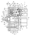
- FIG. 2 is a cross-sectional view taken along line II-II in FIG.
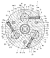
- FIG. 3 is a cross-sectional view taken along line III-III in FIG. 2.
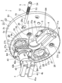
- 1 is an exploded perspective view of a part of a chuck device according to an embodiment of the present invention. It is the figure which looked at the rocking
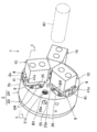
- FIG. 1 shows a chuck device 1 according to an embodiment of the present invention.
- the chuck device 1 is used by being attached to a machine tool such as a lathe, and includes a metal chuck body 2 having a disk shape that can rotate around the rotation axis C1 with a central axis as a rotation axis C1.
- the chuck body 2 includes a bottomed cylindrical case body 2A whose cylinder center line coincides with the rotation axis C1, and a disc-shaped cover body 2B that closes an opening of the case body 2A.
- the case body 2A is an integrally processed product, and includes a disc-shaped front surface portion 2a and a cylindrical peripheral wall portion 2b extending from the outer peripheral edge portion of the front surface portion 2a along the rotation axis C1. .
- a fixing hole 21b extending in the same direction as the rotation axis C1 is formed through the base end side of the bulging portion 21, and the chuck body 2 is attached to a spindle of a machine tool (not shown) using the fixing hole 21b. It can be fixed with the fastening bolt B1.
- Each of the curved concave portions 22 has a shape in which a cross section perpendicular to the rotational axis C1 is gently curved and extends straight in the same direction as the rotational axis C1.
- a pair of flat surface portions 22a extending in parallel with each other along the rotational axis C1 are formed on one inner peripheral surface of the three curved concave portions 22 so as to face each other in the circumferential direction of the chuck body 2. .
- the front surface portion 2a has a swing support hole 24 extending in the same direction as the rotation axis C1 and communicating with the housing space S1 around the first guide hole 23a (rotation shaft).
- the center C1 Around the center C1), three are formed at equal intervals.
- the front surface portion 2 a has an annular first annular step portion 25 extending along the opening periphery of the swing support hole 24, and the opening periphery of the first annular step portion 25. And a second annular stepped portion 26 extending in the direction of the axis, and the second annular stepped portion 26 has a rectangular shape when viewed in the extending direction of the rotation axis C1.
- annular concave groove 27 On the inner peripheral surface of each of the swing support holes 24, as shown in FIG. 4, an annular concave groove 27 having a curved cross section extending annularly around the center line of the swing support hole 24 (in the claims) An example of a “concave portion” is formed continuously with each of the first annular step portions 25.
- a circular entrance / exit opening 27a is formed on the opposite side of the accommodation space S1 in the annular groove 27, and the inner peripheral surface of the entrance / exit opening 27a extends straight along the rotation axis C1. ing.
- a pair of protrusions 27b (protrusions) projecting inwardly of the entrance / exit opening 27a are formed on the periphery of the entrance / exit opening 27a at positions facing the chuck body 2 in the radial direction.
- the strip portion 27b has an arc shape when viewed in the extending direction of the rotation axis C1.
- the chuck body 2 on the inner peripheral surface of the entrance / exit opening 27 a is recessed in a substantially triangular shape as viewed in the extending direction of the rotation axis C ⁇ b> 1 and rotated as shown in FIG. 3.
- a groove-like engagement recess 27c extending along the axis C1 is formed.
- communication holes 28 extending in a direction orthogonal to the radial direction of the front surface portion 2a and straight in the direction orthogonal to the rotation axis C1 are equally spaced around the rotation axis C1. Three are formed.
- Each communication hole 28 corresponds to each swinging support hole 24, and one end of each communication hole 28 opens to a position facing the engagement recess 27 c on the inner circumferential surface of each annular groove 27. The other end of each communication hole 28 opens to the outer peripheral surface of the chuck body 2.
- a female screw portion 28 a is formed on the outer peripheral surface side of the front surface portion 2 a on the inner peripheral surface of each communication hole 28.
- a second guide hole 23b having a circular cross section that extends in the same direction as the rotation axis C1 and communicates with the housing space S1 is formed in the center portion of the cover body 2B. It is formed at a position facing 23a.
- three annular groove portions 2c having an annular shape when viewed from the extending direction of the rotation axis C1 are formed at positions corresponding to the swing support holes 24 of the cover body 2B. Has been.
- plungers 3 having a radial shape as seen in the extending direction of the rotation axis C1 are accommodated.
- the plunger 3 includes a slide shaft portion 31 positioned at the rotation axis C1 and three projecting portions projecting radially from the outer peripheral surface of the middle portion of the slide shaft portion 31 when viewed in the extending direction of the rotation axis C1. 32, and each overhang portion 32 is located inside each of the curved concave portions 22.
- One end side of the slide shaft portion 31 is slidably inserted into the first guide hole 23a formed in the front surface portion 2a of the case body 2A, while the other end side is formed in the cover body 2B.
- the second guide hole 23b is slidably inserted, and the first and second guide holes 23a and 23b guide the slide shaft portion 31, whereby the plunger 3 slides along the rotation axis C1. It is supposed to be.
- a screw guide portion 31 a that opens to one end of the slide shaft portion 31 is formed in approximately one end side of the slide shaft portion 31.
- the other end side of the slide shaft portion 31 is formed with a screw insertion hole 31b that opens to the other end of the slide shaft portion 31 and communicates with the screw guide portion 31a.
- the plunger 3 can be fixed to a draw bar (not shown) of a machine tool using a fastening bolt B2 inserted through the screw insertion hole 31b.
- a pair of positioning surface portions 32a that are slidably in contact with the flat surface portions 22a are formed on the outer peripheral surface of the overhanging portion 32 that is positioned inside the curved concave portion 22 in which both the flat surface portions 22a are formed.
- the positioning surface portions 32a position the plunger 3 around the rotational axis C1.
- a rotation support hole 33 extending in the same direction as the rotation axis C ⁇ b> 1 is formed at the center of each overhang portion 32, and the inner peripheral surface of the rotation support hole 33 is the center of the rotation support hole 33. It is a groove with a curved cross section extending in a ring around the line.
- Each of the rotation support holes 33 is fitted with a ring member 34 (linking means) having a through hole 34a formed in the center.
- the outer peripheral surface of the ring member 34 has a ridge shape having a curved cross section extending annularly around the center line of the ring member 34, and is in surface contact with the inner peripheral surface of the rotation support hole 33 so as to be slidable. ing.
- the chuck body 2 is provided with three master jaws 4 that are substantially T-shaped in a side view.
- the master jaw 4 is provided on one end side of the master jaw 4, and is provided continuously with the attachment portion 41 extending along the radial direction of the chuck body 2 and in the middle portion of the master jaw 4.
- the spherical portion 42 (an example of a “convex portion” in the claims) and the other end side of the master jaw 4 are arranged so as to gradually move toward the rotation axis C1 as the distance from the spherical portion 42 increases.
- an inclined shaft portion 43 having a round bar shape extending in an inclined manner.
- a mounting groove 41a having a substantially T-shaped cross section extends in the mounting portion 41 in the radial direction of the chuck body 2, and a fastened bar 44 having a substantially T-shaped cross section is fitted into the mounting groove 41a. It is.
- a block-shaped top jaw 10 is detachably attached to the to-be-fastened rod 44 using a fastening bolt B3.
- the outer diameter of the spherical portion 42 corresponds to the inner diameter of the entrance / exit opening 27a, and the spherical portion 42 can enter / exit the annular concave groove 27 through the entrance / exit opening 27a. .
- a pair of contact avoiding portions 42a are formed on both side surfaces of the chuck body 2 in the spherical portion 42 in the circumferential direction.
- the both contact avoiding portions 42a have a shallow concave surface with a bottom that is stepped so as to correspond to the shape of the protrusion 27b in the annular groove groove portion 27, and the bottom surface has a gently curved surface.
- the chuck main body 2 slightly protrudes outward in the radial direction.
- the dimension between the two contact avoiding parts 42a corresponds to the dimension between the projecting ends of both projecting part 27b in the annular groove part 27 of the chuck body 2.
- the dimension between the projecting ends of the two protruding ridges 27b in the annular groove groove 27 is set smaller than the outer diameter of the spherical portion 42, and as shown in FIGS.
- the contact avoiding portions 42a are inserted into the annular concave groove 27 from the opposite side of the housing space S1 in a posture corresponding to the projecting ridge portions 27b, the contact avoiding portions 42a are inserted into the projecting ridge portions 27b.
- the inner peripheral surface of the entrance / exit opening 27 a guides the outer peripheral surface of the spherical portion 42 while avoiding contact with the spherical portion 42, and the spherical portion 42 is inserted into the annular groove 27.
- the spherical portion 42 when the spherical portion 42 is inserted into the annular groove groove portion 27, the spherical portion 42 is rotated 90 degrees around the center line of the annular groove groove portion 27, as shown in FIG. A portion of the outer peripheral surface of the spherical portion 42 excluding the contact avoiding portion 42 a corresponds to the protrusions 27 b, whereby the outer peripheral surface of the spherical portion 42 is in sliding contact with the inner peripheral surface of the annular groove groove portion 27.
- the spherical portion 42 is fitted into the annular groove portion 27 in a state where the surface contact is possible.
- the spherical portion 42 is formed with a linear pin insertion hole 42b that passes through the center of the spherical portion 42 and opens in the central portion of each contact avoidance portion 42a, and the spherical portion 42 is formed in the annular recess.
- one end opening of the pin insertion hole 42 b corresponds to the engagement recess 27 c and the other end opening of the pin insertion hole 42 b corresponds to the communication hole 28. .
- the inclined shaft portion 43 is slidably fitted into the through hole 34a of the ring member 34 as shown in FIG.
- the plunger 3 is linked to the other end side of the master jaw 4 via the ring members 34.
- the inclined shaft portion 43 is formed with a housing recess 43a that opens to the opposite side of the mounting portion 41.
- a working hole 4a is formed in the master jaw 4 so as to extend substantially linearly on the central axis of the inclined shaft portion 43 through the central portion of the spherical portion 42.
- One end of the working hole 4a is The other end of the working hole 4a is opened at the center of the bottom surface of the housing recess 43a.
- a threaded portion 4b is formed on the inner peripheral surface at one end of the working hole 4a, and a first set screw 4c is screwed into the threaded portion 4b.
- annular rubber seal member 8 is fitted into the first annular step portion 25, and the seal member 8 is formed between the chuck body 2 and the master jaw 4. It is designed to seal the gap.
- the seal member 8 does not have to be made of a rubber material and may be made of a silicon material.
- a third annular step portion 8 a extending in an annular shape along the outer peripheral edge portion of the seal member 8 is formed on the opposite side of the seal body 8 in the seal member 8.
- a cover plate 9 is fitted into a groove formed by the second annular step portion 26 and the third annular step portion 8a, and the cover plate 9 is fastened to the chuck body 2 with a fastening bolt B4.
- the seal member 8 is attached to the chuck body 2.
- the first coil spring 6 and a slide member 7 having a substantially T shape in a side view are housed inside the housing recess 43a of the inclined shaft portion 43 in the master jaw 4.
- the slide member 7 is composed of an elongated rod-shaped portion 7a and a disc-shaped flange portion 7b provided continuously at one end of the rod-shaped portion 7a.
- the rod-like portion 7a is slidably inserted into the other end side of the working hole 4a, and the slide member 7 is advanced and retracted into the accommodation space S1 by a sliding operation.
- the first coil spring 6 is wound around the rod-shaped portion 7a of the slide member 7, and is in contact with the flange portion 7b of the slide member 7 and the bottom surface of the housing recess 43a.
- the first coil spring 6 moves the slide member 7 so that the slide member 7 advances into the housing space S1 and the flange portion 7b contacts a portion surrounded by the annular groove portion 2c of the cover body 2B. Energized.
- Each master jaw 4 is provided with a rotation restricting mechanism 5 as shown in FIGS.
- the rotation restricting mechanism 5 is screwed into the pin 51 that is slidably inserted into the pin insertion hole 42b, the washer 52 and the second coil spring 53 that are accommodated in the communication hole 28, and the female screw portion 28a.
- the second set screw 54 is used.
- the tip side of the pin 51 has a substantially triangular cross section that gradually becomes narrower as it goes to the tip, and its shape corresponds to the shape of the engagement recess 27c.
- the distal end side of the pin 51 protrudes from the opening portion on one side of the pin insertion hole 42b, while the proximal end side of the pin 51 protrudes from the opening portion on the other side of the pin insertion hole 42b.
- the second coil spring 53 is in contact with the washer 52.
- the tip portion of the pin 51 is adapted to be fitted into the engagement recess 27 c when the pin 51 is biased toward the engagement recess 27 c by the biasing force of the second coil spring 53.
- each master jaw 4 pressed by each ring member 34 swings around the pin 51 (spherical portion 42) while the other end slides with respect to the ring member 34, whereby each master jaw 4 is rotated.
- One end side of the jaw 4 approaches or separates from the rotational axis C1, and accordingly, each top jaw 10 grips the workpiece W1 or releases the gripping state of the workpiece W1. It is like that.
- the master jaw 4 when the top jaws 10 grip the workpiece W ⁇ b> 1, the master jaw 4 has a pin 51 when a force is applied to the master jaw 4 around the center line of the swing support hole 24.
- the ring groove 27 can be slightly rotated around the center line by the gap formed between the outer peripheral surface and the inner peripheral surface of the communication hole 28.
- the master jaw 4 rotates around the center line of the annular groove 27 until the original position is reached by the urging force of the second coil spring 53. Yes.
- the bush as in Patent Document 1 is eliminated from the chuck device 1, the number of parts can be reduced and the number of processing steps, assembly steps, etc. can be reduced, and the inexpensive chuck device 1 can be obtained. Further, the position of the inner peripheral surface of the first guide hole 23a in the chuck body 2 is brought closer to each swing support hole 24 by the amount of the bushing as disclosed in Patent Document 1 around each master jaw 4, and the first guide hole 23a. Therefore, the workpiece W1 can be gripped while inserting a part of the workpiece W1 into the first guide hole 23a, and the restriction when gripping the workpiece W1 can be reduced.
- the outer peripheral surface of the spherical portion 42 is formed into an annular groove simply by sequentially performing an operation of inserting the spherical portion 42 of the master jaw 4 into the annular groove groove portion 27 and an operation of rotating it around the center line of the annular groove groove portion 27. Since the spherical portion 42 is fitted into the annular groove groove portion 27 while being in surface contact with the inner peripheral surface of the groove portion 27 so as to be slidable, the master jaw 4 and the There is no need to separately prepare components other than the chuck body 2, and the chuck device 1 can be made at low cost.
- the outer shape of the seal member 8 when compared with a structure such as Patent Document 1 in which the seal member 8 seals between the bush and the master jaw, there is no restriction that the outer shape of the seal member 8 must be smaller than the outer shape of the bush.
- the dimensions of the outer shape and thickness of the seal member 8 can be made larger than the structure as described above, and the durability of the seal member 8 can be enhanced.
- a pair of protrusions 27b are provided in the annular concave groove 27.
- the protrusions 27b do not have to be a pair and may be one, or three or more. It may be provided.
- the present invention is suitable for a chuck device used by being attached to a machine tool such as a lathe.
Landscapes
- Engineering & Computer Science (AREA)
- Mechanical Engineering (AREA)
- Gripping On Spindles (AREA)
Abstract
Description
好ましくは、前記凹部は、前記揺動支持孔の中心線周りに環状に延びる断面湾曲状の環状凹条溝部であり、前記凸部は、球状をなす球状部である。
好ましくは、環状凹条溝部は、前記収容空間の反対側において出入口開口部を有し、前記出入口開口部は、内径が前記球状部の外径に対応する円形状をなし、前記球状部を前記環状凹条溝部に対して出入りさせ、その周縁において当該出入開口部の内方に突出する突出部が形成され、前記球状部は、その外周面において接触回避部を有し、前記接触回避部は、前記球状部を前記出入開口部から介して前記環状凹条溝部に挿入する際、前記突出部との接触を回避可能に構成され、前記球状部を前記接触回避部が前記突出部に対応する姿勢で前記出入開口部から前記環状凹条溝部に挿入するとともに前記環状凹条溝部の中心線周りに回転させることにより、前記球状部外周面の前記接触回避部を除く部分が前記突出部に対応して、前記球状部が前記環状凹条溝部に嵌合した状態となるように構成される。
好ましくは、前記チャック本体は、一体加工品であるケース体と、前記ケース体の開口部分を塞ぐカバー体とからなる。
好ましくは、プランジャを更に備え、前記プランジャは、前記揺動支持孔における収容空間に収容され、前記各マスタージョウの他端側にそれぞれ連係する複数の連係手段を有し、前記各連係手段は、前記回転軸心に沿うスライド動作により前記各マスタージョウの他端側を押圧し、これにより前記各マスタージョウの一端側を前記回転軸心に対して接近又は離間させることで、前記各トップジョウがワークを把持するか、或いは、上記ワークの把持状態を解除するよう構成されている。
好ましくは、前記ケース体の前面には環状段差部が形成され、前記環状段差部は、前記揺動支持孔の開口周縁に沿って延び、シール部材が嵌め込まれ、これにより前記ケース体と前記マスタージョウとの間がシールされる。
Claims (7)
- チャック装置であって、
チャック本体と、マスタージョウとを備え、
前記チャック本体は、揺動支持孔を有し、
前記揺動支持孔は、前記チャック本体における回転軸心周りに回転可能に複数設けられ、
前記マスタージョウは、
その一端においてトップジョウが着脱可能に設けられ、
前記揺動支持孔に、摺接可能に面接触した状態で嵌合することを特徴とする、
チャック装置。 - 請求項1に記載のチャック装置において、
前記誘導支持孔は、その内周面において凹部を有し、
前記マスタージョウは、その中途部において凸部を有し、
前記凹部の内周面と前記凸部の外周面とが嵌合する、
チャック装置。 - 請求項2に記載のチャック装置において、
前記凹部は、前記揺動支持孔の中心線周りに環状に延びる断面湾曲状の環状凹条溝部であり、
前記凸部は、球状をなす球状部である、
チャック装置。 - 請求項3に記載のチャック装置において、
環状凹条溝部は、前記収容空間の反対側において出入口開口部を有し、前記出入口開口部は、
内径が前記球状部の外径に対応する円形状をなし、
前記球状部を前記環状凹条溝部に対して出入りさせ、
その周縁において当該出入開口部の内方に突出する突出部が形成され、
前記球状部は、その外周面において接触回避部を有し、前記接触回避部は、前記球状部を前記出入開口部から介して前記環状凹条溝部に挿入する際、前記突出部との接触を回避可能に構成され、
前記球状部を前記接触回避部が前記突出部に対応する姿勢で前記出入開口部から前記環状凹条溝部に挿入するとともに前記環状凹条溝部の中心線周りに回転させることにより、前記球状部外周面の前記接触回避部を除く部分が前記突出部に対応して、前記球状部が前記環状凹条溝部に嵌合した状態となるように構成される、
チャック装置。 - 請求項1~請求項4の何れか1つに記載のチャック装置において、
前記チャック本体は、一体加工品であるケース体と、前記ケース体の開口部分を塞ぐカバー体とからなる、
チャック装置。 - 請求項1~請求項5の何れか1つに記載のチャック装置において、
プランジャを更に備え、前記プランジャは、
前記揺動支持孔における収容空間に収容され、
前記各マスタージョウの他端側にそれぞれ連係する複数の連係手段を有し、
前記各連係手段は、前記回転軸心に沿うスライド動作により前記各マスタージョウの他端側を押圧し、これにより前記各マスタージョウの一端側を前記回転軸心に対して接近又は離間させることで、前記各トップジョウがワークを把持するか、或いは、上記ワークの把持状態を解除するよう構成されている、
チャック装置。 - 請求項1~請求項6の何れか1つに記載のチャック装置において、
前記ケース体の前面には環状段差部が形成され、前記環状段差部は、
前記揺動支持孔の開口周縁に沿って延び、
シール部材が嵌め込まれ、これにより前記ケース体と前記マスタージョウとの間がシールされる、
チャック装置。
Priority Applications (5)
| Application Number | Priority Date | Filing Date | Title |
|---|---|---|---|
| KR1020197017624A KR20190088496A (ko) | 2016-11-24 | 2017-11-24 | 척 장치 |
| US16/349,735 US20190329327A1 (en) | 2016-11-24 | 2017-11-24 | Chuck device |
| CN201780058863.6A CN109789493A (zh) | 2016-11-24 | 2017-11-24 | 卡盘装置 |
| EP17873483.6A EP3546096A4 (en) | 2016-11-24 | 2017-11-24 | JIG |
| JP2018552958A JPWO2018097219A1 (ja) | 2016-11-24 | 2017-11-24 | チャック装置 |
Applications Claiming Priority (2)
| Application Number | Priority Date | Filing Date | Title |
|---|---|---|---|
| JP2016228367 | 2016-11-24 | ||
| JP2016-228367 | 2016-11-24 |
Publications (1)
| Publication Number | Publication Date |
|---|---|
| WO2018097219A1 true WO2018097219A1 (ja) | 2018-05-31 |
Family
ID=62195459
Family Applications (1)
| Application Number | Title | Priority Date | Filing Date |
|---|---|---|---|
| PCT/JP2017/042146 Ceased WO2018097219A1 (ja) | 2016-11-24 | 2017-11-24 | チャック装置 |
Country Status (7)
| Country | Link |
|---|---|
| US (1) | US20190329327A1 (ja) |
| EP (1) | EP3546096A4 (ja) |
| JP (1) | JPWO2018097219A1 (ja) |
| KR (1) | KR20190088496A (ja) |
| CN (1) | CN109789493A (ja) |
| TW (1) | TW201827144A (ja) |
| WO (1) | WO2018097219A1 (ja) |
Cited By (1)
| Publication number | Priority date | Publication date | Assignee | Title |
|---|---|---|---|---|
| CN114770574A (zh) * | 2022-04-20 | 2022-07-22 | 连云港中远海运特种装备制造有限公司 | 一种快速夹持压力容器封头的夹持装置 |
Families Citing this family (3)
| Publication number | Priority date | Publication date | Assignee | Title |
|---|---|---|---|---|
| EP3875192A4 (en) * | 2018-10-31 | 2022-08-03 | Howa Machinery, Ltd. | CHUCK CLAW COUPLING MECHANISM |
| JP7467080B2 (ja) * | 2019-11-20 | 2024-04-15 | シチズン時計株式会社 | チャック装置 |
| CN113070502A (zh) * | 2021-04-01 | 2021-07-06 | 浙江京速机床附件有限公司 | 一种强力卡盘 |
Citations (4)
| Publication number | Priority date | Publication date | Assignee | Title |
|---|---|---|---|---|
| US3472526A (en) * | 1967-10-17 | 1969-10-14 | Woodworth Co N A | Universal power chuck |
| JPH0549207U (ja) * | 1991-12-04 | 1993-06-29 | 帝国チャック株式会社 | 旋盤用チャック |
| JP2010519063A (ja) * | 2007-02-27 | 2010-06-03 | イリノイ トゥール ワークス インコーポレイティド | クイックリリース式顎部材並びに一体型軸受チャック |
| JP2011251347A (ja) | 2010-05-31 | 2011-12-15 | Howa Mach Ltd | チャック |
Family Cites Families (5)
| Publication number | Priority date | Publication date | Assignee | Title |
|---|---|---|---|---|
| IT1192814B (it) * | 1986-07-04 | 1988-05-12 | Walter Bronzino | Mandrino automatico autocentrante ed autostaffante |
| EP0415040A3 (en) * | 1989-09-01 | 1991-07-03 | Smw Schneider & Weisshaupt Gmbh | Chuck |
| JPH0777683B2 (ja) * | 1989-12-27 | 1995-08-23 | 日産自動車株式会社 | チャック装置 |
| DE10207567A1 (de) * | 2002-02-22 | 2003-09-04 | Roehm Gmbh | Kugelbolzenfutter |
| DE102011000475A1 (de) * | 2011-02-03 | 2012-08-09 | Röhm Gmbh | Spannfutter |
-
2017
- 2017-11-24 TW TW106140892A patent/TW201827144A/zh unknown
- 2017-11-24 US US16/349,735 patent/US20190329327A1/en not_active Abandoned
- 2017-11-24 JP JP2018552958A patent/JPWO2018097219A1/ja active Pending
- 2017-11-24 EP EP17873483.6A patent/EP3546096A4/en not_active Withdrawn
- 2017-11-24 CN CN201780058863.6A patent/CN109789493A/zh active Pending
- 2017-11-24 WO PCT/JP2017/042146 patent/WO2018097219A1/ja not_active Ceased
- 2017-11-24 KR KR1020197017624A patent/KR20190088496A/ko not_active Withdrawn
Patent Citations (4)
| Publication number | Priority date | Publication date | Assignee | Title |
|---|---|---|---|---|
| US3472526A (en) * | 1967-10-17 | 1969-10-14 | Woodworth Co N A | Universal power chuck |
| JPH0549207U (ja) * | 1991-12-04 | 1993-06-29 | 帝国チャック株式会社 | 旋盤用チャック |
| JP2010519063A (ja) * | 2007-02-27 | 2010-06-03 | イリノイ トゥール ワークス インコーポレイティド | クイックリリース式顎部材並びに一体型軸受チャック |
| JP2011251347A (ja) | 2010-05-31 | 2011-12-15 | Howa Mach Ltd | チャック |
Non-Patent Citations (1)
| Title |
|---|
| See also references of EP3546096A4 |
Cited By (1)
| Publication number | Priority date | Publication date | Assignee | Title |
|---|---|---|---|---|
| CN114770574A (zh) * | 2022-04-20 | 2022-07-22 | 连云港中远海运特种装备制造有限公司 | 一种快速夹持压力容器封头的夹持装置 |
Also Published As
| Publication number | Publication date |
|---|---|
| KR20190088496A (ko) | 2019-07-26 |
| CN109789493A (zh) | 2019-05-21 |
| EP3546096A1 (en) | 2019-10-02 |
| US20190329327A1 (en) | 2019-10-31 |
| EP3546096A4 (en) | 2019-11-06 |
| JPWO2018097219A1 (ja) | 2019-10-17 |
| TW201827144A (zh) | 2018-08-01 |
Similar Documents
| Publication | Publication Date | Title |
|---|---|---|
| WO2018097219A1 (ja) | チャック装置 | |
| US10315316B2 (en) | Floating joint | |
| US10093005B2 (en) | Bit accessory and bit assembly | |
| TWI771556B (zh) | 機器人用末端執行器的安裝結構以及機器人用末端執行器 | |
| JP5729776B2 (ja) | 鉛筆削り | |
| US20170348860A1 (en) | Output device and output system | |
| JP6385347B2 (ja) | メカニカルシール | |
| JPWO2017204273A1 (ja) | チャック装置 | |
| JPH0639914Y2 (ja) | ロータリーナイフ | |
| KR101948787B1 (ko) | 풀다운 척의 공작물 클램핑장치 | |
| JP6964085B2 (ja) | グリッパ | |
| JPH09290340A (ja) | 円形体の心出し装置 | |
| WO2014132849A1 (ja) | パンチ金型 | |
| CN104842179A (zh) | 薄壁圆筒加工夹具 | |
| JP6207988B2 (ja) | マイクロメータおよび測定器 | |
| JP2018114602A (ja) | チャック装置 | |
| JP6979762B2 (ja) | グリッパ | |
| US10835965B2 (en) | Chuck mechanism | |
| JP6663058B1 (ja) | ロボットハンド | |
| JP2010240760A (ja) | ワークの芯出し装置 | |
| KR102591088B1 (ko) | Cnc 머신 장착용 스토퍼 | |
| JP7821861B2 (ja) | 検査のために光学素子を保持する保持装置、及び保持方法 | |
| JP6639045B2 (ja) | 巻線装置用ワーク支持具 | |
| TWI862026B (zh) | 可消除筒夾與刀具背隙之刀桿組 | |
| KR20200013446A (ko) | 가공물 고정용 지그결합체 |
Legal Events
| Date | Code | Title | Description |
|---|---|---|---|
| 121 | Ep: the epo has been informed by wipo that ep was designated in this application |
Ref document number: 17873483 Country of ref document: EP Kind code of ref document: A1 |
|
| ENP | Entry into the national phase |
Ref document number: 2018552958 Country of ref document: JP Kind code of ref document: A |
|
| NENP | Non-entry into the national phase |
Ref country code: DE |
|
| ENP | Entry into the national phase |
Ref document number: 20197017624 Country of ref document: KR Kind code of ref document: A |
|
| ENP | Entry into the national phase |
Ref document number: 2017873483 Country of ref document: EP Effective date: 20190624 |