WO2018097238A1 - Élément de modulation de lumière et support d'enregistrement d'informations - Google Patents
Élément de modulation de lumière et support d'enregistrement d'informations Download PDFInfo
- Publication number
- WO2018097238A1 WO2018097238A1 PCT/JP2017/042183 JP2017042183W WO2018097238A1 WO 2018097238 A1 WO2018097238 A1 WO 2018097238A1 JP 2017042183 W JP2017042183 W JP 2017042183W WO 2018097238 A1 WO2018097238 A1 WO 2018097238A1
- Authority
- WO
- WIPO (PCT)
- Prior art keywords
- light
- image
- optical member
- reproduction
- specific wavelength
- Prior art date
- Legal status (The legal status is an assumption and is not a legal conclusion. Google has not performed a legal analysis and makes no representation as to the accuracy of the status listed.)
- Ceased
Links
Images












Classifications
-
- G—PHYSICS
- G03—PHOTOGRAPHY; CINEMATOGRAPHY; ANALOGOUS TECHNIQUES USING WAVES OTHER THAN OPTICAL WAVES; ELECTROGRAPHY; HOLOGRAPHY
- G03H—HOLOGRAPHIC PROCESSES OR APPARATUS
- G03H1/00—Holographic processes or apparatus using light, infrared or ultraviolet waves for obtaining holograms or for obtaining an image from them; Details peculiar thereto
- G03H1/0005—Adaptation of holography to specific applications
- G03H1/0011—Adaptation of holography to specific applications for security or authentication
-
- B—PERFORMING OPERATIONS; TRANSPORTING
- B42—BOOKBINDING; ALBUMS; FILES; SPECIAL PRINTED MATTER
- B42D—BOOKS; BOOK COVERS; LOOSE LEAVES; PRINTED MATTER CHARACTERISED BY IDENTIFICATION OR SECURITY FEATURES; PRINTED MATTER OF SPECIAL FORMAT OR STYLE NOT OTHERWISE PROVIDED FOR; DEVICES FOR USE THEREWITH AND NOT OTHERWISE PROVIDED FOR; MOVABLE-STRIP WRITING OR READING APPARATUS
- B42D25/00—Information-bearing cards or sheet-like structures characterised by identification or security features; Manufacture thereof
- B42D25/30—Identification or security features, e.g. for preventing forgery
- B42D25/351—Translucent or partly translucent parts, e.g. windows
-
- G—PHYSICS
- G03—PHOTOGRAPHY; CINEMATOGRAPHY; ANALOGOUS TECHNIQUES USING WAVES OTHER THAN OPTICAL WAVES; ELECTROGRAPHY; HOLOGRAPHY
- G03H—HOLOGRAPHIC PROCESSES OR APPARATUS
- G03H1/00—Holographic processes or apparatus using light, infrared or ultraviolet waves for obtaining holograms or for obtaining an image from them; Details peculiar thereto
- G03H1/02—Details of features involved during the holographic process; Replication of holograms without interference recording
- G03H1/024—Hologram nature or properties
- G03H1/0248—Volume holograms
-
- G—PHYSICS
- G03—PHOTOGRAPHY; CINEMATOGRAPHY; ANALOGOUS TECHNIQUES USING WAVES OTHER THAN OPTICAL WAVES; ELECTROGRAPHY; HOLOGRAPHY
- G03H—HOLOGRAPHIC PROCESSES OR APPARATUS
- G03H1/00—Holographic processes or apparatus using light, infrared or ultraviolet waves for obtaining holograms or for obtaining an image from them; Details peculiar thereto
- G03H1/04—Processes or apparatus for producing holograms
- G03H1/16—Processes or apparatus for producing holograms using Fourier transform
-
- G—PHYSICS
- G03—PHOTOGRAPHY; CINEMATOGRAPHY; ANALOGOUS TECHNIQUES USING WAVES OTHER THAN OPTICAL WAVES; ELECTROGRAPHY; HOLOGRAPHY
- G03H—HOLOGRAPHIC PROCESSES OR APPARATUS
- G03H1/00—Holographic processes or apparatus using light, infrared or ultraviolet waves for obtaining holograms or for obtaining an image from them; Details peculiar thereto
- G03H1/22—Processes or apparatus for obtaining an optical image from holograms
- G03H1/2249—Holobject properties
-
- G—PHYSICS
- G03—PHOTOGRAPHY; CINEMATOGRAPHY; ANALOGOUS TECHNIQUES USING WAVES OTHER THAN OPTICAL WAVES; ELECTROGRAPHY; HOLOGRAPHY
- G03H—HOLOGRAPHIC PROCESSES OR APPARATUS
- G03H1/00—Holographic processes or apparatus using light, infrared or ultraviolet waves for obtaining holograms or for obtaining an image from them; Details peculiar thereto
- G03H1/22—Processes or apparatus for obtaining an optical image from holograms
- G03H1/2286—Particular reconstruction light ; Beam properties
-
- G—PHYSICS
- G03—PHOTOGRAPHY; CINEMATOGRAPHY; ANALOGOUS TECHNIQUES USING WAVES OTHER THAN OPTICAL WAVES; ELECTROGRAPHY; HOLOGRAPHY
- G03H—HOLOGRAPHIC PROCESSES OR APPARATUS
- G03H1/00—Holographic processes or apparatus using light, infrared or ultraviolet waves for obtaining holograms or for obtaining an image from them; Details peculiar thereto
- G03H1/22—Processes or apparatus for obtaining an optical image from holograms
- G03H1/24—Processes or apparatus for obtaining an optical image from holograms using white light, e.g. rainbow holograms
-
- B—PERFORMING OPERATIONS; TRANSPORTING
- B42—BOOKBINDING; ALBUMS; FILES; SPECIAL PRINTED MATTER
- B42D—BOOKS; BOOK COVERS; LOOSE LEAVES; PRINTED MATTER CHARACTERISED BY IDENTIFICATION OR SECURITY FEATURES; PRINTED MATTER OF SPECIAL FORMAT OR STYLE NOT OTHERWISE PROVIDED FOR; DEVICES FOR USE THEREWITH AND NOT OTHERWISE PROVIDED FOR; MOVABLE-STRIP WRITING OR READING APPARATUS
- B42D25/00—Information-bearing cards or sheet-like structures characterised by identification or security features; Manufacture thereof
- B42D25/30—Identification or security features, e.g. for preventing forgery
- B42D25/328—Diffraction gratings; Holograms
-
- B—PERFORMING OPERATIONS; TRANSPORTING
- B42—BOOKBINDING; ALBUMS; FILES; SPECIAL PRINTED MATTER
- B42D—BOOKS; BOOK COVERS; LOOSE LEAVES; PRINTED MATTER CHARACTERISED BY IDENTIFICATION OR SECURITY FEATURES; PRINTED MATTER OF SPECIAL FORMAT OR STYLE NOT OTHERWISE PROVIDED FOR; DEVICES FOR USE THEREWITH AND NOT OTHERWISE PROVIDED FOR; MOVABLE-STRIP WRITING OR READING APPARATUS
- B42D25/00—Information-bearing cards or sheet-like structures characterised by identification or security features; Manufacture thereof
- B42D25/30—Identification or security features, e.g. for preventing forgery
- B42D25/36—Identification or security features, e.g. for preventing forgery comprising special materials
- B42D25/378—Special inks
-
- G—PHYSICS
- G03—PHOTOGRAPHY; CINEMATOGRAPHY; ANALOGOUS TECHNIQUES USING WAVES OTHER THAN OPTICAL WAVES; ELECTROGRAPHY; HOLOGRAPHY
- G03H—HOLOGRAPHIC PROCESSES OR APPARATUS
- G03H1/00—Holographic processes or apparatus using light, infrared or ultraviolet waves for obtaining holograms or for obtaining an image from them; Details peculiar thereto
- G03H1/02—Details of features involved during the holographic process; Replication of holograms without interference recording
- G03H1/0276—Replicating a master hologram without interference recording
- G03H2001/0292—Replicating a master hologram without interference recording by masking
-
- G—PHYSICS
- G03—PHOTOGRAPHY; CINEMATOGRAPHY; ANALOGOUS TECHNIQUES USING WAVES OTHER THAN OPTICAL WAVES; ELECTROGRAPHY; HOLOGRAPHY
- G03H—HOLOGRAPHIC PROCESSES OR APPARATUS
- G03H1/00—Holographic processes or apparatus using light, infrared or ultraviolet waves for obtaining holograms or for obtaining an image from them; Details peculiar thereto
- G03H1/26—Processes or apparatus specially adapted to produce multiple sub- holograms or to obtain images from them, e.g. multicolour technique
- G03H2001/2605—Arrangement of the sub-holograms, e.g. partial overlapping
- G03H2001/262—Arrangement of the sub-holograms, e.g. partial overlapping not in optical contact
-
- G—PHYSICS
- G03—PHOTOGRAPHY; CINEMATOGRAPHY; ANALOGOUS TECHNIQUES USING WAVES OTHER THAN OPTICAL WAVES; ELECTROGRAPHY; HOLOGRAPHY
- G03H—HOLOGRAPHIC PROCESSES OR APPARATUS
- G03H2222/00—Light sources or light beam properties
- G03H2222/10—Spectral composition
- G03H2222/12—Single or narrow bandwidth source, e.g. laser, light emitting diode [LED]
-
- G—PHYSICS
- G03—PHOTOGRAPHY; CINEMATOGRAPHY; ANALOGOUS TECHNIQUES USING WAVES OTHER THAN OPTICAL WAVES; ELECTROGRAPHY; HOLOGRAPHY
- G03H—HOLOGRAPHIC PROCESSES OR APPARATUS
- G03H2222/00—Light sources or light beam properties
- G03H2222/10—Spectral composition
- G03H2222/17—White light
Definitions
- the present disclosure relates to a light modulation element and an information recording medium using the light modulation element.
- JP-A-10-153944 a Fourier transform image of an original image is generated and binarized using a computer, and a plurality of binarized Fourier transform images are arranged on a film as a transparent and black pattern.
- a Fourier transform hologram which is a light modulation element manufactured in this manner, is disclosed.
- a point light source is placed behind the film and the point light source is observed through the film. Then, a point-symmetric image can be visually recognized around the point light source corresponding to the Fourier transform image in the film.
- the Fourier transform hologram is irradiated with white light containing a plurality of wavelength components during reproduction, there is a problem that the reproduced light image is observed in a rainbow color with wavelength dispersion.
- the size of the reproduced light image is small, the visibility of the reproduced light image is deteriorated when observed with a rainbow color dispersed in wavelength. Therefore, when the reproduced light image represents a character or a symbol, the character or the symbol may not be correctly identified due to wavelength dispersion.
- the present disclosure is for solving the above-described problem, and the purpose thereof is light modulation capable of visually reconstructing a reproduced light image in a desired color when an optical member is observed using light from a point light source.
- An element and an information recording medium are provided.
- a reproduction reference image for reproducing an original image light having a specific wavelength is reflected or absorbed, and at least the specific light in the visible light band is specified.
- a light modulation element including an optical member having a light control unit that transmits light other than the wavelength and a light transmission unit that transmits light in at least the visible light band including the specific wavelength.
- the reproduction reference image may be a Fourier transform image of the original image.
- the optical member has a hologram recording layer
- the light control unit may be interference fringes in the hologram recording layer.
- the optical member is incident from a point light source in a normal direction of the optical member in a state where light in a predetermined wavelength band including the specific wavelength is incident on a predetermined region including the interference fringes in the hologram recording layer.
- a reproduction light image of the color having the specific wavelength is visually recognized.
- the reproduction light image is shorter than the specific wavelength.
- a reproduction light image having a wavelength color may be visually recognized.
- the optical member is incident from a point light source in a normal direction of the optical member in a state where light in a predetermined wavelength band including the specific wavelength is incident on a predetermined region including the interference fringes in the hologram recording layer.
- a reproduction light image of the color having the specific wavelength is visually recognized, and the point light source is transmitted through the predetermined region from a direction closer to the normal direction than the inclined direction.
- a reproduced light image having a color longer than the specific wavelength may be visually recognized.
- the optical member is A base material layer; A dielectric multilayer film laminated on the base material layer,
- the light control unit may be the dielectric multilayer film.
- the optical member passes through the predetermined region from a normal direction of the optical member in a state in which light of a predetermined wavelength band including the specific wavelength is incident on a predetermined region including the dielectric multilayer film from a point light source.
- a reproduction light image of the color having the specific wavelength is visually recognized, and when the point light source is observed through the predetermined region from a direction inclined from the normal direction, a color having a shorter wavelength than the specific wavelength is observed.
- a reproduced light image may be visually recognized.
- the optical member is from a direction inclined from the normal direction of the optical member in a state in which light of a predetermined wavelength band including the specific wavelength is incident on a predetermined region including the dielectric multilayer film from a point light source.
- a reproduction light image of the color of the specific wavelength is visually recognized, and when the point light source is observed through the predetermined region from a direction closer to the normal direction than the inclined direction, the A reproduced light image having a color longer than the specific wavelength may be visually recognized.
- the optical member is A base material layer; A specific wavelength absorption layer laminated on the base material layer,
- the light control unit may be the specific wavelength absorption layer.
- a reproduction light image having a color of a specific wavelength may be visually recognized.
- the half-value width of the spectral transmittance of the specific wavelength when light of a predetermined wavelength band including the specific wavelength is incident on the optical member along the normal direction of the optical member from a point light source is 100 nm or less. There may be.
- An information recording medium including the above-described light modulation element may be provided.
- the original image may include information such as characters, symbols, and patterns.
- At least a part of the light modulation element may be disposed in the opening.
- a reproduced light image can be visually recognized in a desired color.
- FIG. 1 is a schematic cross-sectional view of a light modulation element 1 according to an embodiment of the present disclosure.
- 6 is a flowchart showing an example of a procedure of a method for manufacturing the light modulation element 1.
- Process drawing explaining the 1st example of the manufacturing method of the light modulation element of FIG. Process drawing following FIG. 3A.
- the process drawing following FIG. 3B The figure which shows an example of a Fourier-transform image.
- Process drawing explaining the 2nd example of the manufacturing method of the light modulation element of FIG. The process drawing following FIG. 5A.
- FIG. 5B The figure which shows the method of observing the reproduction light image of a hologram recording layer from a normal line direction.
- FIG. 5 The figure which shows the method of observing the reproduction light image of a hologram recording layer from a normal line direction.
- FIG. 6B is a diagram showing an example of the reproduced light image in FIG. 6A.
- FIG. 18 is a diagram showing a second example of a cross-sectional structure taken along line AA of the information recording medium in FIG. 17.
- FIG. 18 is a diagram showing a third example of a cross-sectional structure taken along the line AA of the information recording medium in FIG. 17.
- FIG. 18 is a diagram showing a fourth example of a cross-sectional structure taken along the line AA of the information recording medium in FIG. 17.
- FIG. 20 is a diagram showing a first example of a cross-sectional structure taken along line AA of FIG.
- FIG. 20 is a diagram showing a second example of a cross-sectional structure taken along the line AA of FIG.
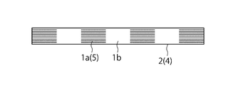
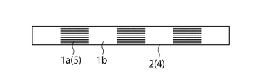
- FIG. 1 is a schematic cross-sectional view of a light modulation element 1 according to an embodiment of the present disclosure.
- the light modulation element 1 in FIG. 1 includes an optical member 2 having a light control unit 1a and a light transmission unit 1b.
- the light control unit 1a reflects or absorbs light of a specific wavelength according to a reproduction reference image for reproducing an original image, and transmits at least light of a specific wavelength in the visible light band.
- the reproduction reference image is an image having light intensity distribution and phase distribution corresponding to the original image, and is, for example, a Fourier transform image of the original image.
- the light transmission part 1b transmits light in at least the visible light band including the specific wavelength.
- the visible light band is, for example, a wavelength range of 360 to 830 nm.
- the specific wavelength is a partial wavelength band within the visible light band.
- the wavelength band of the specific wavelength of the present disclosure is a wavelength range at both ends of the half-value width of the spectral transmittance in the light control unit 1a.
- the half width of the spectral transmittance is the transmittance (%) of the optical member 2 assumed when the light control unit 1a is not formed at the wavelength where the transmittance is minimum, and the transmittance.
- the transmittance (%) of the optical member 2 at the wavelength at which the minimum value is a is defined as a
- the transmittance is (b + a) / 2
- the specific wavelength may be a green wavelength band of 495 to 570 nm. More preferably, it may be a green wavelength band of 507 to 557 nm.
- the narrower the wavelength band the higher the monochromaticity of the reconstructed light image, the less blurred the reconstructed light image due to chromatic dispersion, and the clear reconstructed light image can be observed. This is because a change in the hue of the scenery around the reproduction light image seen through the modulation element 1 is reduced.
- the optical member 2 may be a hologram recording layer 4 having a light control unit 1a and a light transmission unit 1b.
- the light control unit 1 a in the hologram recording layer 4 may be the interference fringes 5 in the hologram recording layer 4.
- the optical member 2 is more desirable as the transmittance in the visible light band is higher. Specifically, the transmittance is desirably 60% or more, and particularly desirably 70% or more. The higher the transmittance of the optical member 2, the better the visibility of the optical image by the optical member 2.
- the transmittance is a value measured according to JIS K7361-1.
- the optical member 2 is desirable as the haze value is lower.
- the haze value is preferably in the range of 0.01% to 5%, and particularly preferably in the range of 0.01% to 1.5%.
- the haze value is a value measured according to JIS K7136.
- the hologram recording layer 4 is formed by recording interference fringes 5 on a volume hologram recording material, for example.
- the interference fringes 5 correspond to the light control unit 1a.
- the hologram recording layer 4 includes a region where the interference fringes 5 are formed and a region where the interference fringes 5 are not formed, and the region where the interference fringes 5 are not formed corresponds to the light transmission portion 1b.
- the half-value width of the spectral transmittance representing the width of the specific wavelength transmitted through the hologram recording layer 4 is desirably 100 nm or less in order to improve the color discrimination performance and obtain a clear reproduced light image. More preferably, the half width is desirably 50 nm or less.
- the volume hologram recording material is not particularly limited as long as it has values within the allowable ranges of transmittance and haze value described above.
- a photosensitive material containing a silver salt material, a dichromated gelatin emulsion, a photopolymer resin, a photocrosslinkable resin, a cationic polymerizable compound, a radical polymerizable compound, a photo radical polymerization initiator system, and a photo cationic polymerization initiator system Etc. are used.
- the interference fringes 5 inside the hologram recording layer 4 are formed by making light of a specific wavelength incident on the volume hologram recording material from the first direction.
- the first direction may be a normal direction of the optical member 2.
- the optical member 2 emits light in a predetermined wavelength band including a specific wavelength from a point light source in a predetermined region partially including the interference fringes 5 in the hologram recording layer 4 along the normal direction of the optical member 2.
- a reproduction light image having a specific wavelength is visually recognized.
- the optical member 2 observes a point light source through a predetermined region from a direction inclined from the normal direction, a reproduction light image having a color shorter than the specific wavelength is visually recognized.
- the predetermined region is a region including the light control unit 1a and the light transmission unit 1b corresponding to the Fourier transform image in the hologram recording layer 4, and is a region where the reproduction light image can be visually recognized.
- the reproduction light image cannot be visually recognized only by the light control unit 1a or the light transmission unit 1b.
- the first direction described above may be a direction inclined from the normal direction of the optical member 2.
- the optical member 2 is in a normal direction of the optical member 2 in a state where light in a predetermined wavelength band including a specific wavelength is incident from a point light source on a predetermined region partially including interference fringes in the hologram recording layer 4.
- a point light source is observed through a predetermined region from a direction inclined from the center, a reproduced light image having a specific wavelength is visually recognized.
- the optical member 2 observes the point light source through a predetermined region from a direction closer to the normal direction than the inclined direction, a reproduction light image having a color longer than the specific wavelength is visually recognized.
- FIG. 2 is a flowchart showing an example of a procedure of a method for manufacturing the light modulation element 1
- FIGS. 3A to 3C are process diagrams corresponding to the procedure of FIG.
- a Fourier transform image is generated.
- the Fourier transform image is generated by performing processing such as Fourier transform on the original image using a computer. Specifically, first, an original image is generated on a personal computer (hereinafter, PC) (step S1).
- PC personal computer
- the original image is an arbitrary character, symbol, pattern, or the like.
- a Fourier transform image of the original image is generated using a computer such as a PC (step S2).
- the Fourier transform image is binarized (step S3). That is, the phase is examined for each pixel of the Fourier transform image, and when the phase is from minus 90 degrees to plus 90 degrees, a certain value Tp, for example, transparent is assigned, and in other cases, another certain value Tm, for example, black or Binarization is performed by assigning mirror surfaces.
- the range for assigning Tp may be set to a value other than minus 90 degrees and plus 90 degrees.
- FIG. 4 shows an example of the Fourier transform image 10.
- the Fourier transform image 10 of FIG. 4 is binary data of black and white, but may be composed of multi-value data having more than binary values.
- An optical image reproduced based on the Fourier transform image 10 is a point-symmetric optical image with respect to a predetermined center position.
- the binarized Fourier transform image obtained in step S3 is arranged in a desired range (step S4).
- a Fourier transform image in which four binarized Fourier transform images are arranged is generated.
- a Fourier transform image is generated by arranging, for example, 20 images of the minimum unit vertically and horizontally.
- the Fourier transform image 10 includes an image in which images of minimum units such as FIG. 4 are arranged in a desired range.
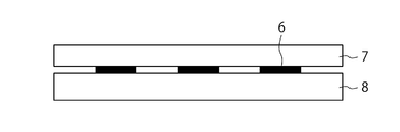
- a light absorption layer or a reflection layer is formed on the glass substrate, and a photomask substrate 7 is produced by patterning the light absorption layer or the reflection layer according to the Fourier transform image 10 (step S5).
- the white portion of the Fourier transform image 10 in FIG. 4 is a photomask on which the Fourier transform image 10 is recorded by removing the light absorption layer or reflection layer by etching and leaving the light absorption layer or reflection layer as it is in the black portion.
- a substrate 7 is produced.
- the light absorbing layer may be patterned on the film base material according to the Fourier transform image 10 by a method for producing a printing plate-making film using laser recording.
- an example using the photomask substrate 7 will be described.
- step S6 light of a specific wavelength is irradiated from both sides with the photomask substrate 7 superimposed on the volume hologram recording material 8 (step S6).
- the irradiation light coherent light L1 having the same phase and wavelength is used.
- light incident on the light absorption layer 6 in the photomask substrate 7 is absorbed and not incident on the volume hologram recording material 8.
- the light passing through the portion without the light absorption layer 6 in the photomask substrate 7 penetrates the photomask substrate 7 as it is and enters the volume hologram recording material 8. As shown in FIG.
- the light from both sides interferes to form an interference fringe 5 (step S7).
- the interference fringes 5 are formed at locations that do not overlap the light absorption layer 6 in the photomask substrate 7.
- the formation location of the light absorption layer 6 corresponds to the light transmission portion 1b.
- the light transmitting portion 1b is disposed.
- the light modulation element 1 is obtained by removing the photomask substrate 7 (step S8).
- FIG. 5A to 5C are process diagrams for explaining another example of the manufacturing method of the light modulation element 1 of FIG.
- a photomask substrate 7 is disposed below the volume hologram recording material 8, and light having a specific wavelength is incident from above the volume hologram recording material 8.
- An example using a photomask substrate will also be described with reference to FIG.
- the interference fringes 5 corresponding to the Fourier transform image 10 are formed in the volume hologram recording material 8.
- the interference fringes 5 reflect light having a specific wavelength and transmit light having a wavelength other than the specific wavelength, and correspond to the light control unit 1a.
- the light control unit 1a and the light transmission unit 1b in the region without the interference fringes 5 form a reproduction light image because light of a specific wavelength does not pass through the light control unit 1a but passes through the light transmission unit 1b.
- Light other than the wavelength is transmitted through both the light control unit 1a and the light transmission unit 1b, so that a reproduction light image is not formed. Therefore, according to the manufacturing methods of FIGS. 3A to 3C and FIGS. 5A to 5C, it is possible to visually recognize a single color reproduction light image by providing the light control unit 1a and the light transmission unit 1b.
- FIGS. 3A to 3C and FIGS. 5A to 5C show an example in which the interference fringes 5 are formed by causing the coherent light L1 to enter the photomask substrate 7 and the volume hologram recording material 8 from the normal direction.
- the interference fringes 5 may be formed by making the coherent light L1 incident from a direction inclined with respect to the normal direction.
- a dielectric multilayer film may be used.
- the light modulation element 1 is manufactured using the dielectric multilayer film, for example, after the dielectric multilayer film is laminated on the base material layer by vapor deposition or vapor phase growth method, a photomask substrate patterned according to the Fourier transform image 10 may be disposed, and the dielectric multilayer film may be patterned by an etching process using photolithography.
- a patterned dielectric multilayer film may be formed on the base material layer by an electron beam drawing method or the like instead of using a photomask substrate. In this case, a certain part of the dielectric multilayer film corresponds to the interference fringe 5 and serves as the light control unit 1a.
- the half-value width of the spectral transmittance representing the width of the specific wavelength transmitted through the patterned dielectric multilayer film is preferably 100 nm or less in order to improve the color discrimination performance and obtain a clear reproduction light image. More preferably, the half width is desirably 50 nm or less.
- the optical member 2 having a dielectric multilayer film is a normal direction of the optical member 2 in a state where light from a point light source 11 in a predetermined wavelength band including a specific wavelength is incident on a predetermined region partially including the dielectric multilayer film.
- a reproduction light image having a specific wavelength is visually recognized.
- the point light source 11 is observed through the predetermined region from a direction inclined from the normal direction, a color having a shorter wavelength than the specific wavelength is observed. A reproduced light image is visually recognized.
- the optical member 2 having a dielectric multilayer film is a method of the optical member 2 in a state where light from a point light source 11 in a predetermined wavelength band including a specific wavelength is incident on a predetermined region partially including the dielectric multilayer film.
- a reproduction light image having a specific wavelength is visually recognized, and when the point light source 11 is observed through the predetermined area from a direction closer to the normal direction than the inclined direction.
- a reproduced light image having a color longer than the specific wavelength is visually recognized.
- the light modulation element 1 selects the color of the reproduced light image to be visually recognized by controlling the incident direction and wavelength of the laser light used when forming the interference fringes 5 in the volume hologram recording material 8. be able to. Further, by controlling the interlayer distance of the dielectric multilayer film and the refractive index of each layer, it is possible to select the color of the visually reproduced light image. In addition, the color of the visually reconstructed light image changes also by changing the viewing direction.
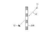
- FIG. 6A is a diagram showing a method of observing a reproduction light image of the hologram recording layer 4 produced in FIGS. 3A to 3C or FIGS. 5A to 5C.
- light from the point light source 11 is incident on a predetermined region along the normal direction of the hologram recording layer 4, and an observer 12 is seen from the surface side opposite to the point light source 11 with respect to the hologram recording layer 4.
- the predetermined region is a region including the light control unit 1a and the light transmission unit 1b corresponding to the Fourier transform image in the hologram recording layer 4, and is a region where the reproduced light image can be visually recognized.
- the region where the interference fringes 5 are formed is the light control unit 1a, and the region where the interference fringes 5 are not formed is the light transmission unit 1b.
- the light from the point light source 11 is light in a predetermined wavelength band including a specific wavelength. As a more specific example, the light from the point light source 11 may be light of a specific wavelength or white light.
- the point light source 11 does not need to be coherent light L1, but is preferably light including a relatively wide wavelength component such as LED light or an incandescent lamp.
- the interference fringe 5 of the present embodiment is a light control unit 1a that reflects light without passing through a specific wavelength and transmits light with a wavelength other than the specific wavelength.
- the area where the interference fringes 5 are not recorded is a light transmitting portion 1b that transmits light having a specific wavelength and light having a wavelength other than the specific wavelength. Therefore, the optical member 2 reflects and transmits light corresponding to the Fourier transform image with respect to light having a specific wavelength, and only transmits light with respect to light having a wavelength other than the specific wavelength.
- the reproduced light image can be visually recognized with the color of the specific wavelength.
- FIG. 7A shows an example in which the observer 12 observes the point light source 11 through a predetermined area along a direction inclined from the normal direction of the hologram recording layer 4.
- the color of the reproduced light image that is visually recognized is shorter. Shift to the wavelength side.
- the color visually recognized from the normal direction is green
- the color of the reproduction light image becomes bluish as the inclination angle from the normal direction increases.
- the visual sensitivity of the human eye is maximum in green, and the visual sensitivity decreases as it approaches blue. Therefore, as the observation direction of the observer 12 is inclined from the normal direction, the reproduced light image is as shown in FIG. 7B. It becomes difficult to see.
- the interference fringes 5 are formed in the hologram recording layer 4 by making the coherent light L1 having a specific wavelength incident along the normal direction of the hologram recording layer 4, the direction from the direction inclined with respect to the normal direction.
- the point light source 11 is observed through a predetermined region including the region where the interference fringes 5 are formed, a color (visible when viewed from the normal direction) and shifted to a shorter wavelength side than the wavelength used for forming the interference fringes ( For example, since the color is visually recognized with a blue color), the visibility may be reduced.
- FIG. 8 is a diagram showing another example of manufacturing the interference fringes 5 in the hologram recording layer 4.
- coherent light L 1 having a specific wavelength is incident on the volume hologram recording material 8 along a direction inclined from the normal direction of the volume hologram recording material 8, and interference fringes 5 are formed inside the volume hologram recording material 8.
- the incident coherent light is compared. Even if the wavelength of the light L1 is the same, the latter has a wider pitch in the normal direction of the interference fringes 5.
- the pitch of the interference fringes 5 in the normal direction increases, and the greater the inclination angle from the normal direction, the greater the interference.
- the pitch in the normal direction of the stripes 5 becomes wider.
- FIG. 9A shows an example in which the point light source 11 is observed through a predetermined region including the formation region of the interference fringe 5 from the same direction as the incident direction of the coherent light L1 when the interference fringe 5 of FIG. 8 is formed.
- the reproduced light image is visually recognized with a color having the same wavelength as the coherent light used when the interference fringes 5 are formed.
- FIG. 10A shows an example in which the point light source 11 is observed from a normal direction of the hologram recording layer 4 on which the interference fringes 5 shown in FIG.
- the color of the reproduced light image is shifted to a color on the longer wavelength side than the predetermined wavelength.
- the color of the wavelength of the coherent light used when the interference fringe 5 is formed is green
- the point light source 11 is observed through a predetermined region along the normal direction, it is visually recognized as a reddish color, for example, orange. Since the reddish color has higher visibility than the blue color, the visibility is better than that of the blue color.
- the interference fringes 5 are formed in the volume hologram recording material 8
- the green coherent light L1 having a predetermined wavelength is not incident along the normal direction but is inclined with respect to the normal direction.
- the angle range in which the reproduced light image can be visually recognized can be widened.
- the hologram recording layer 4 when observing the reproduction light image of the interference fringes 5 formed in the hologram recording layer 4, the hologram recording layer 4 is moved from the surface side opposite to the surface side where the point light source 11 of the hologram recording layer 4 is arranged. Although the example which observes was demonstrated, you may arrange
- FIG. 1 the example which observes was demonstrated, you may arrange
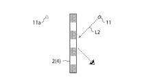
- FIG. 11A and FIG. 11B are diagrams showing an example in which the point light source 11 is arranged on the same surface side as the observer 12 and the reproduction light image is observed.
- an LED is used as the point light source 11.
- the hologram recording of the point light source 11 is performed.
- a reproduced light image can be visually recognized at a position 11a that is plane-symmetric with respect to the layer.
- FIG. 12 shows an example in which a laser pointer 11 b that emits coherent light L ⁇ b> 3 is used as the point light source 11.
- the laser pointer 11b is similarly used.
- the coherent light L1 incident on the hologram recording layer 4 along the normal direction of the hologram recording layer 4 the reproduced image 24 with a color of a predetermined wavelength is applied to the predetermined projection surface 14 on the opposite surface side of the hologram recording layer 4.
- the observer 12 can visually recognize the reproduced image 24 by observing the projection plane without passing through a predetermined region including the light control unit 1a and the light transmission unit 1b in the hologram recording layer 4.
- the example in which the interference fringe 5 that reflects the light of the specific wavelength is formed in the hologram recording layer 4 is shown.
- the light of the specific wavelength is formed on the base material layer.
- a specific wavelength absorption layer containing a specific wavelength absorbing dye that absorbs a green wavelength component which is a specific wavelength is formed on the base material layer. It may be formed in accordance with a Fourier transform image on the upper surface to be a predetermined region where the reproduced light image can be observed.
- the part with the specific wavelength absorbing dye is the light control unit 1a.
- dye becomes the light transmissive part 1b.
- the ink containing the specific wavelength absorbing dye is used as the base material layer.
- a method of forming on top of this can be considered.
- Specific materials for the specific wavelength absorbing dye include tetraazaporphyrins, cyanine dyes, azomethine dyes, rhodamine dyes and the like used in color filters and the like.
- polyethylene terephthalate, polycarbonate, acrylic resin, cycloolefin resin, polyester resin, polystyrene resin, acrylic styrene resin, or other resin films having high transmittance and low haze value, quartz glass, and the like are used.
- the half-value width of the spectral transmittance that represents the width of the specific wavelength transmitted by the specific wavelength absorbing dye formed on the base material layer is 100 nm or less in order to improve the color discrimination performance and obtain a clear reproduction light image. desirable. More preferably, the half width is desirably 50 nm or less.
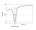
- FIG. 13 is a graph showing the spectral transmittance distribution of the light control unit 1a.
- the horizontal axis represents wavelength (nm) and the vertical axis represents transmittance (%).
- the light control unit 1a in FIG. 13 is an interference fringe 5, a dielectric multilayer film, a specific wavelength absorbing dye, or the like.
- the above-described half width (full width at half maximum) c is the transmittance (%) of the optical member 2 assumed when the light control unit 1a is not formed at the wavelength where the transmittance is minimum, and the transmittance is minimum.
- the transmittance (%) of the optical member 2 at a wavelength becomes a is defined as the difference between the wavelengths before and after the wavelength closest to the wavelength at which the transmittance is minimum, where the transmittance is (b + a) / 2. .
- the light modulation element 1 controls the incident light and the wavelength of the laser beam used when forming the interference fringes 5 in the volume hologram recording material 8 to visually recognize the reproduced light image.
- the color can be selected. Therefore, when two or more types of laser beams having different wavelengths are used when forming the interference fringes 5, reproduction light images of two or more types of colors can be visually recognized.
- FIG. 14 shows an example of a reproduced light image including two different colors.
- the letters “F” with different shades in FIG. 14 actually represent different colors. More specifically, for example, red “F” 31 and green “F” 32 are arranged diagonally.
- the light modulation element 1 capable of reproducing the reproduction light image of FIG. 14 can be manufactured by the procedure shown in FIG. 2 and FIGS. 3A to 3C. More specifically, a volume hologram capable of obtaining a red reproduction light image using the red “F” photomask substrate 7, and a green color using the green “F” photomask substrate 7.
- a volume hologram from which a reproduction light image can be obtained is produced, and the hologram recording layer 4 in which these two volume holograms are laminated is irradiated with a laser beam containing red and green wavelength components, whereby a red and green reproduction light image is obtained. Can be obtained.
- an interference fringe is formed in the hologram recording material 8 by irradiating a laser beam containing a red wavelength component, and then the arrangement of the photomask substrate 7 is arranged.
- Another interference fringe may be formed in the hologram recording material 8 by irradiating a laser beam containing a green wavelength component with the direction shifted.
- the light control unit 1a in the light modulation element 1 for obtaining the reproduced light image of FIG. 14 transmits light in a predetermined wavelength band including two wavelengths from the point light source as interference fringes in the hologram recording layer 4.
- the point light source is observed through the predetermined region from the normal direction of the optical member 2 in a state where it is incident on a predetermined predetermined region, two different reproduction light images are visually recognized.
- FIG. 15A shows a first example of a reproduced light image of the light modulation element 1 manufactured using three or more laser beams having different wavelengths.
- the reproduced light image in FIG. 15A represents white “F” 33.
- the reproduction light image has three or more formed in the light modulation element 1 when the light modulation element 1 is irradiated with reproduction illumination light including all wavelength components of the three or more laser beams used at the time of production.
- the light diffracted by each of the interference fringes is mixed with each other, and as a result, it is observed in white.
- the light modulation element 1 for obtaining the reproduction light image of FIG. 15A prepares, for example, three or more photomask substrates 7 corresponding to each of three or more wavelength components, and sets the photomask substrate 7 for each wavelength. Three or more interference fringes may be formed in the volume hologram recording medium 8 while changing.
- a plurality of volume holograms can be produced by which a plurality of color reproduction light images can be obtained using a plurality of photomask substrates 7 corresponding to each of three or more wavelength components, and these volume holograms can be laminated. Good.
- a white reproduction light image can be obtained by simultaneously irradiating the laminated hologram recording layer 4 with laser light having the same wavelength as that used during recording.
- the wavelength range of the laser beam used to obtain the white reproduction light image may be three or more laser beams of the red, green, and blue wavelength ranges, or other wavelength ranges. Three or more laser beams may be used.
- the light control unit 1a in the light modulation element 1 for obtaining the reproduction light image in FIG. 15A causes the light in the predetermined wavelength band including three or more wavelengths to interfere with the light in the hologram recording layer 4 from the point light source.
- the point light source is observed through the predetermined region from the normal direction of the optical member 2 in a state where the light is incident on the predetermined region partially including the stripe, a white reproduction light image is visually recognized.
- FIG. 15B shows a second example of a reproduction light image of the light modulation element 1 manufactured using three or more laser beams having different wavelengths.
- the reproduced light image in FIG. 15B is color-coded by three or more colors.
- the regions with different shading in FIG. 15B indicate that the colors are different.
- the light modulation element 1 in FIG. 15B is produced by using three photomask substrates 7 corresponding to three colors to produce three volume holograms for obtaining a reproduction light image of a plurality of colors, and laminating these volume holograms. is there.
- a plurality of reproduction light images illuminated with one or more colors can be obtained.
- the light modulation element 1 of FIG. 15B forms interference fringes in the volume hologram recording medium 8 by irradiating laser light having a different wavelength for each placement position while shifting the placement location of one photomask substrate 7. May be.
- the light control unit 1a in the light modulation element 1 for obtaining the reproduction light image of FIG. 15B transmits light in a predetermined wavelength band including three or more wavelengths from the point light source to the interference in the hologram recording layer 4.
- a point light source is observed through a predetermined region from the normal direction of the optical member 2 in a state where it is incident on a predetermined region partially including a stripe, a reproduction light image colored in three or more colors is visually recognized It is.
- the light modulation element 1 according to the present embodiment can be combined with an existing light modulation element that highlights a two-dimensional or three-dimensional reproduced light image.
- the hologram recording layer 4 on which the interference fringes 5 of the present embodiment are recorded and the existing hologram recording layer that causes a two-dimensional or three-dimensional reproduction light image (also called a Lippmann hologram reproduction image) to emerge are laminated.
- an interference fringe in the existing hologram recording layer that causes a two-dimensional or three-dimensional reproduction light image to emerge is formed in the hologram recording layer 4 according to the present embodiment separately or simultaneously with the interference fringe 5. May be.
- the light modulation element 1 reproduces not only the hologram recording layer 4 produced by the procedures of FIGS. 2 and 3A to 3C (or FIGS. 5A to 5C) but also a Lippmann hologram reproduction image.
- the interference fringes may be provided.
- the interference fringes for reproducing the Lippmann hologram reproduction image may be formed on the hologram recording layer 4 on which the interference fringes for reproducing the reproduction light image corresponding to the reproduction reference image such as a Fourier transform image are formed, It may be formed in a recording material layer different from the hologram recording layer 4.
- FIG. 16A and FIG. 16B are diagrams for explaining a reproduction method of this type of light modulation element 1.
- the reproduction illumination light for reproducing the reproduction light image 34 corresponding to the reproduction reference image is different from the reproduction illumination light for reproducing the Lippmann hologram reproduction image 35. More specifically, the reproduction illumination light for reproducing the reproduction light image 34 corresponding to the reproduction reference image is a point light source arranged away from one main surface of the light modulation element 1 as shown in FIG. 16A. It is the light from 11a. The observer observes the reproduction light image 34 from the surface side opposite to the one main surface of the light modulation element 1 with the point light source 11a turned on. On the other hand, as shown in FIG.
- the reproduction illumination light for reproducing the Lippmann hologram reproduction image 35 is, for example, from another point light source 11b arranged at a position separated from one main surface of the light modulation element 1. Irradiated in a direction inclined with respect to the normal direction of the main surface. The observer observes the Lippmann hologram reproduction image 35 from the normal direction of one main surface.
- the Lippmann hologram reproduction image 35 is visible not only with the point light source 11b but also with another illumination light source such as a fluorescent lamp.
- the Lippmann hologram reproduction image 35 is illuminated with light irradiated in a direction inclined with respect to the normal direction of one principal surface, and is observed from the normal direction, that is, the observer is from a direction deviating from the direction of the light source.
- the reproduction light image 34 corresponding to the reproduction reference image can be observed from the direction of the point light source. Therefore, there is no fear that the Lippmann hologram reproduction image 35 and the reproduction light image 34 corresponding to the reproduction reference image are mixed and observed, and both reproduction images can be clearly distinguished and observed.
- the reproduction illumination light for reproducing the Lippmann hologram reproduction image 35 may be the point light source 11b or another illumination light source as described above.
- the point light source 11a it is necessary to place the point light source 11a on the side opposite to the observer with the light modulation element 1 interposed therebetween.
- the reproduced light image 34 can be reproduced even when the observer observes from the same side as the point light source 11a. In this case, from the specular reflection direction of the light from the point light source 11a. The observer needs to observe.
- the reproduction light image 34 is used for security purposes such as forgery prevention.
- the original for reproducing the Lippmann hologram reproduction image 35 is produced, for example, by the existing two-step method (also called the H1H2 method).
- a volume hologram can be formed by stacking an original produced by the H1H2 method on a photomask substrate and irradiating a laser beam with a predetermined wavelength from a predetermined direction.
- an interference fringe is formed in the volume hologram recording medium 8 using an original produced by the H1H2 method, and the procedure of FIG. 3A to FIG. 3C or FIG. 5A to FIG. 5C is performed using the formed volume hologram recording medium 8
- the final hologram recording layer 4 may be formed.
- the color of the Lippmann hologram reproduction image 35 can be controlled by the wavelength of the laser beam when forming the interference fringes.
- the reproduction illumination light irradiated when reproducing the Lippmann hologram reproduction image 35 needs to include the wavelength component of the reference light used when forming the interference fringes.
- the wavelength of the laser light used when forming the interference fringes corresponding to the reproduction light image 34 corresponding to the reproduction reference image and the laser light used when forming the interference fringes corresponding to the Lippmann hologram reproduction image 35 are obtained.
- the reproduction light image 34 and the Lippmann hologram reproduction image 35 corresponding to the reproduction reference image can be made the same color or different from each other.
- the color type can be arbitrarily adjusted.
- FIG. 17 is a diagram illustrating an example of the information recording medium 20.
- the information recording medium 20 in FIG. 17 is a medium on which various information such as personal information such as banknotes, ID certificates, passports, cash vouchers, tickets, and public documents, and confidential information is recorded, or a medium having a monetary value.
- the ID card is a national ID card, a license, a membership card, an employee card, a student card, or the like.
- the substrate of the medium in FIG. 17 is paper, resin, metal, synthetic fiber, or the like. The substrate of FIG.
- the 17 is provided with an opening 21, and at least a part of the opening 21 is provided with a transparent member 22 in which security information such as characters, symbols, and patterns is recorded as a Fourier transform image. .
- the entire area of the opening 21 may be covered with the transparent member 22, or the transparent member 22 may be disposed only on a part of the opening 21.
- the transparent member 22 corresponds to the light modulation element 1 according to the present embodiment.
- a point light source is arranged on the back surface side of the information recording medium 20 in FIG. 17, and the observer observes the point light source through the transparent member 22 from the front surface side, whereby the security information recorded on the transparent member 22 is obtained. It can be visually recognized.
- This security information can be used, for example, for authenticity determination of the information recording medium 20.
- FIG. 18A is a diagram showing a first example of a cross-sectional structure taken along line AA of the information recording medium 20 of FIG.
- the opaque resin layer 32 is disposed on the transparent resin layer 31.
- the opaque resin layer 32 is provided with an opening 33 in a region overlapping with the opening 21.
- the light modulation element 1 described above is disposed on the opening 33, and the transparent resin layer 34 is disposed thereon. Thereby, the reproduction image according to the Fourier transform image formed in the light modulation element 1 can be visually recognized by illuminating the opening 21 with light from the point light source.
- the opening 33 may be formed by making a hole in the opaque resin layer 32, or after making a hole in the opaque resin layer 32, a transparent resin layer having the same shape as the hole is formed in the hole. May be. 18A shows that there is a gap between the transparent resin layer 34 and the opaque resin layer 32, but when used as the information recording medium 20, the transparent resin layer 34 and the transparent resin layer 34 are exposed to heat and pressure. The opaque resin layer 32 is fused, or the transparent resin layer 34 and the opaque resin layer 32 are bonded via an adhesive (not shown).
- FIG. 18B is a diagram showing a second example of a cross-sectional structure taken along line AA of the information recording medium 20 of FIG.
- the information recording medium 20 shown in FIG. 18B is different from FIG. 18A in that a printing layer 35 is disposed on the back side of the transparent resin layer 34.
- the print layer 35 is disposed on the back surface of the transparent resin layer 34 so as not to overlap with the opening 21. That is, the opening 21 is provided at a location overlapping the portion where the print layer 35 is not disposed.
- the print layer 35 may be provided on the upper surface side instead of the back surface side of the transparent resin layer 34.
- the transparent resin layer 34 and the opaque resin layer 32 may be fused by applying heat and pressure, or may be bonded via an adhesive (not shown).
- FIG. 18C is a diagram showing a third example of a cross-sectional structure taken along line AA of the information recording medium 20 of FIG.
- the opaque resin layer 32 is disposed on the transparent resin layer 31, and the transparent resin layer 34 is disposed thereon.
- the light modulation element 1 is arranged in accordance with the position of the opening 21.
- the opaque resin layer 32 is provided with an opening 33 in a region overlapping with the opening 21.
- FIG. 18D is a diagram showing a fourth example of a cross-sectional structure taken along line AA of the information recording medium 20 of FIG.
- the print layer 36 is disposed on the transparent resin layer 31 so as to avoid a region overlapping the opening 21.
- a transparent resin layer 34 is disposed on the print layer 36, and a print layer 37 is disposed on the transparent resin layer 34 so as to avoid a region overlapping the opening 21.
- a transparent resin layer 38 is disposed on the printing layer 37, and the light modulation element 1 is disposed on the transparent resin layer 38 according to the position of the opening 21. That is, the opening 21 is provided at a location overlapping the portion where the print layers 36 and 37 are not disposed.
- the transparent resin layers 31, 34, 38 may be fused by applying heat and pressure, or may be bonded via an adhesive (not shown).
- FIG. 19 is a diagram showing another example of the information recording medium 20.
- the information recording medium 20 in FIG. 19 is a bill.
- the banknote of FIG. 19 is provided with an opening 21. At least a part of the opening 21 is provided with a transparent member 22 that records security information such as characters, symbols, and patterns as a Fourier transform image.
- FIG. 20A is a diagram showing a first example of a cross-sectional structure taken along line AA of FIG.
- a print layer 42 is disposed so as to avoid a region overlapping the opening 21.
- the light modulation element 1 is disposed in a region overlapping the opening 21.
- a transparent resin layer 43 is disposed on the light modulation element 1.
- a print layer 44 is disposed so as to avoid a region overlapping with the opening 21. That is, the opening 21 is provided at a location overlapping the portion where the print layers 42 and 44 are not disposed.
- the transparent resin layers 41 and 43 may be fused by applying heat and pressure, or may be bonded via an adhesive (not shown).
- 20B is a diagram showing a second example of the cross-sectional structure taken along the line AA of FIG.
- Print layers 42 and 44 are disposed on the back surface side and the top surface side of the transparent resin layer 41 so as not to overlap the opening 21.
- the light modulation element 1 is disposed in a region overlapping the opening on the upper surface side of the transparent resin layer 41. That is, the opening 21 is provided at a location overlapping the portion where the print layers 42 and 44 are not disposed.
- the light modulation element 1 according to the present embodiment can be determined with the naked eye by only a small point light source 11 such as an easily available LED light. Further, the light modulation element 1 according to the present embodiment has a feature that authenticity can be determined by confirming a reproduction light image of a color of a specific wavelength, unlike the conventional rainbow color. Furthermore, the light modulation element 1 according to the present embodiment has a feature that the color of the reproduced light image changes by changing the incident direction of the point light source 11 to the light modulation element 1, and the authenticity determination can be more reliably performed. Can do.
- the light modulation element 1 according to the present embodiment has a narrow half-value width of the spectral transmittance of the optical member 2 of 100 nm or less, more preferably 50 nm or less, the reproduced light image is clear and easy to visually check, and authenticity can be easily determined. It has the feature of being. Further, since the light modulation element 1 according to the present embodiment has a high transmittance, it is easy to observe the scene ahead through the opening 21 of the information recording medium 20.
- this embodiment includes the optical member 2 having the light control unit 1a and the light transmission unit 1b corresponding to the Fourier transform image 10 of the original image, and the light control unit 1a reflects light of a specific wavelength.
- a point light source 11 is used to reproduce a reproduction light image when a predetermined region including the light control unit 1a and the light transmission unit 1b in the optical member 2 is observed.
- the color becomes a single color, making it easier to visually recognize the reproduced light image. That is, since the light modulation element 1 according to the present embodiment has little wavelength dispersion of the reproduction light image, the outline of the reproduction light image becomes clear and a clear reproduction light image can be visually recognized.
- the color of the reproduced light image is controlled by adjusting the incident direction and wavelength of the coherent light L1 used when forming the interference fringes 5 in the hologram recording layer 4 constituting the optical member 2.
- the angle range in which the reproduced light image can be clearly seen can be controlled.
- the point light source 11 when observing the reproduction light image, may be disposed on the surface opposite to the viewer 12 with respect to the optical member 2, or the same surface side as the viewer 12.
- the point light source 11 may be arranged in the position, and the degree of freedom with respect to the location of the point light source 11 is increased.
Landscapes
- Physics & Mathematics (AREA)
- General Physics & Mathematics (AREA)
- Engineering & Computer Science (AREA)
- Computer Security & Cryptography (AREA)
- Mathematical Physics (AREA)
- Holo Graphy (AREA)
- Credit Cards Or The Like (AREA)
Abstract
La présente invention permet de reconnaître visuellement une image de lumière reproduite en une couleur souhaitée lorsqu'un élément optique est observé à l'aide d'une lumière provenant d'une source de lumière ponctuelle. Un élément de modulation de lumière (1) est pourvu d'un élément optique (2) comprenant une partie de commande de lumière (1a) qui, en fonction d'une image de référence de reproduction pour reproduire une image d'origine, réfléchit ou absorbe la lumière ayant une longueur d'onde spécifique et transmet la lumière ayant des longueurs d'onde autres que la longueur d'onde spécifique hors de la lumière dans au moins une bande de lumière visible, et une partie de transmission de lumière (1b) qui transmet la lumière dans au moins la bande de lumière visible comprenant la longueur d'onde spécifique.
Priority Applications (6)
| Application Number | Priority Date | Filing Date | Title |
|---|---|---|---|
| CN201780072517.3A CN109983408B (zh) | 2016-11-24 | 2017-11-24 | 光调制元件和信息记录介质 |
| EP23210926.4A EP4303029B1 (fr) | 2016-11-24 | 2017-11-24 | Élément de modulation de lumière et support d'enregistrement d'informations |
| JP2018552970A JP7153234B2 (ja) | 2016-11-24 | 2017-11-24 | 光変調素子および情報記録媒体 |
| EP17874562.6A EP3547039B1 (fr) | 2016-11-24 | 2017-11-24 | Élément de modulation de lumière et support d'enregistrement d'informations |
| CN202111133941.9A CN113835322B (zh) | 2016-11-24 | 2017-11-24 | 光调制元件和信息记录介质 |
| US16/464,027 US11703798B2 (en) | 2016-11-24 | 2017-11-24 | Light modulation element and information recording medium |
Applications Claiming Priority (2)
| Application Number | Priority Date | Filing Date | Title |
|---|---|---|---|
| JP2016-228229 | 2016-11-24 | ||
| JP2016228229 | 2016-11-24 |
Publications (1)
| Publication Number | Publication Date |
|---|---|
| WO2018097238A1 true WO2018097238A1 (fr) | 2018-05-31 |
Family
ID=62195897
Family Applications (1)
| Application Number | Title | Priority Date | Filing Date |
|---|---|---|---|
| PCT/JP2017/042183 Ceased WO2018097238A1 (fr) | 2016-11-24 | 2017-11-24 | Élément de modulation de lumière et support d'enregistrement d'informations |
Country Status (5)
| Country | Link |
|---|---|
| US (1) | US11703798B2 (fr) |
| EP (2) | EP3547039B1 (fr) |
| JP (1) | JP7153234B2 (fr) |
| CN (2) | CN113835322B (fr) |
| WO (1) | WO2018097238A1 (fr) |
Cited By (3)
| Publication number | Priority date | Publication date | Assignee | Title |
|---|---|---|---|---|
| JP2019215498A (ja) * | 2018-06-14 | 2019-12-19 | 大日本印刷株式会社 | 光変調素子および情報記録媒体 |
| WO2020080367A1 (fr) | 2018-10-16 | 2020-04-23 | 凸版印刷株式会社 | Corps d'affichage tridimensionnel intégré et procédé d'enregistrement d'informations d'identification |
| JPWO2022154042A1 (fr) * | 2021-01-18 | 2022-07-21 |
Families Citing this family (1)
| Publication number | Priority date | Publication date | Assignee | Title |
|---|---|---|---|---|
| CN111933676B (zh) * | 2020-08-18 | 2023-09-19 | 京东方科技集团股份有限公司 | 一种显示面板及其制作方法、显示装置 |
Citations (10)
| Publication number | Priority date | Publication date | Assignee | Title |
|---|---|---|---|---|
| JPH06313812A (ja) * | 1993-04-30 | 1994-11-08 | Dainippon Printing Co Ltd | ホログラムを用いたカラーフィルタ及びその作製方法 |
| US5455693A (en) * | 1992-09-24 | 1995-10-03 | Hughes Aircraft Company | Display hologram |
| JPH10153943A (ja) | 1996-09-25 | 1998-06-09 | Dainippon Printing Co Ltd | ホログラムの作成方法およびホログラム |
| JP2000347555A (ja) * | 1999-04-02 | 2000-12-15 | Dainippon Printing Co Ltd | 透過観察が可能な反射型ホログラム |
| JP2004126535A (ja) | 2002-08-02 | 2004-04-22 | Dainippon Printing Co Ltd | ホログラム観察具とそのための計算機ホログラム |
| JP2007041545A (ja) * | 2005-07-06 | 2007-02-15 | Dainippon Printing Co Ltd | ホログラム観察シート |
| JP2013092624A (ja) * | 2011-10-25 | 2013-05-16 | Dainippon Printing Co Ltd | ホログラムシート |
| JP2016085355A (ja) | 2014-10-27 | 2016-05-19 | 大日本印刷株式会社 | 表示物 |
| JP2016090659A (ja) * | 2014-10-30 | 2016-05-23 | 大日本印刷株式会社 | 反射型体積ホログラムを含むセキュリティ媒体の真贋判定装置、反射型体積ホログラムを含むセキュリティ媒体の真贋判定方法、及び反射型体積ホログラムを含むセキュリティ媒体 |
| JP2016117185A (ja) * | 2014-12-19 | 2016-06-30 | 凸版印刷株式会社 | 表示体、表示体付き物品および真贋判定方法 |
Family Cites Families (20)
| Publication number | Priority date | Publication date | Assignee | Title |
|---|---|---|---|---|
| JP2512044B2 (ja) * | 1987-12-08 | 1996-07-03 | 松下電器産業株式会社 | 光記録媒体及び光記録方法 |
| US5153670A (en) * | 1990-01-12 | 1992-10-06 | Physical Optics Corporation | Holographic lippmann-bragg filter in a spectroscopic system |
| US5549953A (en) * | 1993-04-29 | 1996-08-27 | National Research Council Of Canada | Optical recording media having optically-variable security properties |
| US6737154B2 (en) * | 1995-06-26 | 2004-05-18 | 3M Innovative Properties Company | Multilayer polymer film with additional coatings or layers |
| JP2000272300A (ja) * | 1999-03-26 | 2000-10-03 | Shiseido Co Ltd | 偽造防止粘着シールおよびその製造方法 |
| EP1872178A2 (fr) * | 2005-01-21 | 2008-01-02 | Ver-Tec Security Systems Limited | Hologrammes de securite |
| WO2006077447A2 (fr) * | 2005-01-21 | 2006-07-27 | Ver-Tec Security Systems Limited | Support d'enregistrement holographique |
| US8941904B2 (en) * | 2005-07-04 | 2015-01-27 | Dai Nippon Printing Co., Ltd. | Hologram sheet and hologram observation sheet using same, and blinding device |
| JP5206915B2 (ja) | 2005-07-04 | 2013-06-12 | 大日本印刷株式会社 | 目隠し装置及び目隠し装置の製造方法 |
| US9001401B2 (en) * | 2005-12-13 | 2015-04-07 | Dai Nippon Printing Co., Ltd. | Fabrication process of multi-image type hologram, and multi-image type hologram fabricated by that process |
| CN100517128C (zh) * | 2006-03-09 | 2009-07-22 | 佳能株式会社 | 显示装置、全息再现装置和利用全息图的装置 |
| JP2008097682A (ja) * | 2006-10-10 | 2008-04-24 | Funai Electric Co Ltd | 光記録媒体、光記録媒体の情報の記録方法及び再生方法 |
| US8228576B2 (en) * | 2008-08-11 | 2012-07-24 | Dai Nippon Printing Co., Ltd. | Transmission type optical element and anti-forgery volume hologram |
| DE102008062149B3 (de) * | 2008-12-16 | 2010-04-29 | Ovd Kinegram Ag | Verfahren zur Herstellung eines Sicherheitselements sowie Transferfolie |
| JP5482988B2 (ja) * | 2009-04-27 | 2014-05-07 | 大日本印刷株式会社 | 偽造防止媒体 |
| JP5748130B2 (ja) * | 2010-09-08 | 2015-07-15 | 大日本印刷株式会社 | 照明装置、投射装置および投写型映像表示装置 |
| US20130003151A1 (en) * | 2011-06-29 | 2013-01-03 | Sabic Innovative Plastics Ip B.V. | Holographic storage method and article |
| WO2013061803A1 (fr) * | 2011-10-27 | 2013-05-02 | 大日本印刷株式会社 | Dispositif de projection |
| DE102014013049A1 (de) | 2014-09-03 | 2016-03-03 | Giesecke & Devrient Gmbh | Optisch variables Sicherheitselement |
| EP3336612A4 (fr) * | 2015-08-13 | 2019-06-26 | Dai Nippon Printing Co., Ltd. | Structure d'hologramme |
-
2017
- 2017-11-24 WO PCT/JP2017/042183 patent/WO2018097238A1/fr not_active Ceased
- 2017-11-24 EP EP17874562.6A patent/EP3547039B1/fr active Active
- 2017-11-24 EP EP23210926.4A patent/EP4303029B1/fr active Active
- 2017-11-24 CN CN202111133941.9A patent/CN113835322B/zh active Active
- 2017-11-24 CN CN201780072517.3A patent/CN109983408B/zh active Active
- 2017-11-24 US US16/464,027 patent/US11703798B2/en active Active
- 2017-11-24 JP JP2018552970A patent/JP7153234B2/ja active Active
Patent Citations (10)
| Publication number | Priority date | Publication date | Assignee | Title |
|---|---|---|---|---|
| US5455693A (en) * | 1992-09-24 | 1995-10-03 | Hughes Aircraft Company | Display hologram |
| JPH06313812A (ja) * | 1993-04-30 | 1994-11-08 | Dainippon Printing Co Ltd | ホログラムを用いたカラーフィルタ及びその作製方法 |
| JPH10153943A (ja) | 1996-09-25 | 1998-06-09 | Dainippon Printing Co Ltd | ホログラムの作成方法およびホログラム |
| JP2000347555A (ja) * | 1999-04-02 | 2000-12-15 | Dainippon Printing Co Ltd | 透過観察が可能な反射型ホログラム |
| JP2004126535A (ja) | 2002-08-02 | 2004-04-22 | Dainippon Printing Co Ltd | ホログラム観察具とそのための計算機ホログラム |
| JP2007041545A (ja) * | 2005-07-06 | 2007-02-15 | Dainippon Printing Co Ltd | ホログラム観察シート |
| JP2013092624A (ja) * | 2011-10-25 | 2013-05-16 | Dainippon Printing Co Ltd | ホログラムシート |
| JP2016085355A (ja) | 2014-10-27 | 2016-05-19 | 大日本印刷株式会社 | 表示物 |
| JP2016090659A (ja) * | 2014-10-30 | 2016-05-23 | 大日本印刷株式会社 | 反射型体積ホログラムを含むセキュリティ媒体の真贋判定装置、反射型体積ホログラムを含むセキュリティ媒体の真贋判定方法、及び反射型体積ホログラムを含むセキュリティ媒体 |
| JP2016117185A (ja) * | 2014-12-19 | 2016-06-30 | 凸版印刷株式会社 | 表示体、表示体付き物品および真贋判定方法 |
Non-Patent Citations (1)
| Title |
|---|
| See also references of EP3547039A4 |
Cited By (7)
| Publication number | Priority date | Publication date | Assignee | Title |
|---|---|---|---|---|
| JP2019215498A (ja) * | 2018-06-14 | 2019-12-19 | 大日本印刷株式会社 | 光変調素子および情報記録媒体 |
| JP7263702B2 (ja) | 2018-06-14 | 2023-04-25 | 大日本印刷株式会社 | 光変調素子および情報記録媒体 |
| WO2020080367A1 (fr) | 2018-10-16 | 2020-04-23 | 凸版印刷株式会社 | Corps d'affichage tridimensionnel intégré et procédé d'enregistrement d'informations d'identification |
| US11356649B2 (en) | 2018-10-16 | 2022-06-07 | Toppan Printing Co., Ltd. | Integrated three dimensional display and method of recording identification information |
| JPWO2022154042A1 (fr) * | 2021-01-18 | 2022-07-21 | ||
| WO2022154042A1 (fr) * | 2021-01-18 | 2022-07-21 | 大日本印刷株式会社 | Stratifié d'hologramme volumique, feuille de transfert d'hologramme volumique, étiquette d'hologramme volumique, carte, page de données et livre |
| JP2023103215A (ja) * | 2021-01-18 | 2023-07-26 | 大日本印刷株式会社 | 体積ホログラム積層体、体積ホログラム転写箔、体積ホログラムラベル、カード、データページおよび冊子類 |
Also Published As
| Publication number | Publication date |
|---|---|
| EP4303029B1 (fr) | 2025-05-14 |
| US20190384222A1 (en) | 2019-12-19 |
| CN113835322A (zh) | 2021-12-24 |
| JP7153234B2 (ja) | 2022-10-14 |
| US11703798B2 (en) | 2023-07-18 |
| CN113835322B (zh) | 2023-12-29 |
| CN109983408B (zh) | 2021-10-22 |
| EP3547039B1 (fr) | 2024-03-13 |
| EP3547039A1 (fr) | 2019-10-02 |
| JPWO2018097238A1 (ja) | 2019-10-17 |
| EP4303029A2 (fr) | 2024-01-10 |
| EP3547039A4 (fr) | 2020-05-27 |
| EP4303029A3 (fr) | 2024-04-24 |
| CN109983408A (zh) | 2019-07-05 |
Similar Documents
| Publication | Publication Date | Title |
|---|---|---|
| RU2452627C2 (ru) | Видимый насквозь защитный элемент с микроструктурами | |
| CN103847289B (zh) | 具有再现隐藏图像的光学防伪元件及用其制成的产品 | |
| CN104025160B (zh) | 衍射装置 | |
| JP7153234B2 (ja) | 光変調素子および情報記録媒体 | |
| SE1951442A1 (en) | An optical security device and method of manufacture | |
| JP2015068849A (ja) | 表示体及びラベル付き物品 | |
| JP5041187B2 (ja) | 真贋判定ホログラム作製方法 | |
| GB2588183A (en) | Optical device and method of manufacture thereof | |
| JP2022527666A (ja) | プラズモン効果を有する光学セキュリティコンポーネント、そのようなコンポーネントの製造、そのようなコンポーネントを備えたセキュリティオブジェクト | |
| JP5350187B2 (ja) | 識別媒体およびその識別方法 | |
| JP5082378B2 (ja) | 表示体及び印刷物 | |
| JP4338124B2 (ja) | 体積ホログラム記録体 | |
| JPWO2019070081A1 (ja) | ホログラム素子、情報記録媒体、ラベル体、転写箔体、カード、ホログラムシート及びホログラム複製方法 | |
| JP5626622B2 (ja) | 体積型ホログラムの製造方法 | |
| JP6382482B2 (ja) | 回折格子記録媒体 | |
| US20080259417A1 (en) | Holographic Recording Media | |
| JP6399316B2 (ja) | 回折格子記録媒体 | |
| CN113646671A (zh) | 显示体 | |
| JP2004077858A (ja) | 導波路すかし |
Legal Events
| Date | Code | Title | Description |
|---|---|---|---|
| 121 | Ep: the epo has been informed by wipo that ep was designated in this application |
Ref document number: 17874562 Country of ref document: EP Kind code of ref document: A1 |
|
| ENP | Entry into the national phase |
Ref document number: 2018552970 Country of ref document: JP Kind code of ref document: A |
|
| NENP | Non-entry into the national phase |
Ref country code: DE |
|
| ENP | Entry into the national phase |
Ref document number: 2017874562 Country of ref document: EP Effective date: 20190624 |