WO2018100721A1 - Procédé de traitement de panneau, panneau et dispositif de traitement de panneau - Google Patents
Procédé de traitement de panneau, panneau et dispositif de traitement de panneau Download PDFInfo
- Publication number
- WO2018100721A1 WO2018100721A1 PCT/JP2016/085784 JP2016085784W WO2018100721A1 WO 2018100721 A1 WO2018100721 A1 WO 2018100721A1 JP 2016085784 W JP2016085784 W JP 2016085784W WO 2018100721 A1 WO2018100721 A1 WO 2018100721A1
- Authority
- WO
- WIPO (PCT)
- Prior art keywords
- panel
- sealant
- insert
- bottom plate
- processing method
- Prior art date
- Legal status (The legal status is an assumption and is not a legal conclusion. Google has not performed a legal analysis and makes no representation as to the accuracy of the status listed.)
- Ceased
Links
Images





Classifications
-
- F—MECHANICAL ENGINEERING; LIGHTING; HEATING; WEAPONS; BLASTING
- F16—ENGINEERING ELEMENTS AND UNITS; GENERAL MEASURES FOR PRODUCING AND MAINTAINING EFFECTIVE FUNCTIONING OF MACHINES OR INSTALLATIONS; THERMAL INSULATION IN GENERAL
- F16B—DEVICES FOR FASTENING OR SECURING CONSTRUCTIONAL ELEMENTS OR MACHINE PARTS TOGETHER, e.g. NAILS, BOLTS, CIRCLIPS, CLAMPS, CLIPS OR WEDGES; JOINTS OR JOINTING
- F16B5/00—Joining sheets or plates, e.g. panels, to one another or to strips or bars parallel to them
- F16B5/01—Joining sheets or plates, e.g. panels, to one another or to strips or bars parallel to them by means of fastening elements specially adapted for honeycomb panels
-
- B—PERFORMING OPERATIONS; TRANSPORTING
- B32—LAYERED PRODUCTS
- B32B—LAYERED PRODUCTS, i.e. PRODUCTS BUILT-UP OF STRATA OF FLAT OR NON-FLAT, e.g. CELLULAR OR HONEYCOMB, FORM
- B32B15/00—Layered products comprising a layer of metal
- B32B15/20—Layered products comprising a layer of metal comprising aluminium or copper
-
- B—PERFORMING OPERATIONS; TRANSPORTING
- B32—LAYERED PRODUCTS
- B32B—LAYERED PRODUCTS, i.e. PRODUCTS BUILT-UP OF STRATA OF FLAT OR NON-FLAT, e.g. CELLULAR OR HONEYCOMB, FORM
- B32B27/00—Layered products comprising a layer of synthetic resin
- B32B27/18—Layered products comprising a layer of synthetic resin characterised by the use of special additives
- B32B27/20—Layered products comprising a layer of synthetic resin characterised by the use of special additives using fillers, pigments, thixotroping agents
-
- B—PERFORMING OPERATIONS; TRANSPORTING
- B32—LAYERED PRODUCTS
- B32B—LAYERED PRODUCTS, i.e. PRODUCTS BUILT-UP OF STRATA OF FLAT OR NON-FLAT, e.g. CELLULAR OR HONEYCOMB, FORM
- B32B3/00—Layered products comprising a layer with external or internal discontinuities or unevennesses, or a layer of non-planar shape; Layered products comprising a layer having particular features of form
- B32B3/10—Layered products comprising a layer with external or internal discontinuities or unevennesses, or a layer of non-planar shape; Layered products comprising a layer having particular features of form characterised by a discontinuous layer, i.e. formed of separate pieces of material
- B32B3/12—Layered products comprising a layer with external or internal discontinuities or unevennesses, or a layer of non-planar shape; Layered products comprising a layer having particular features of form characterised by a discontinuous layer, i.e. formed of separate pieces of material characterised by a layer of regularly- arranged cells, e.g. a honeycomb structure
-
- B—PERFORMING OPERATIONS; TRANSPORTING
- B32—LAYERED PRODUCTS
- B32B—LAYERED PRODUCTS, i.e. PRODUCTS BUILT-UP OF STRATA OF FLAT OR NON-FLAT, e.g. CELLULAR OR HONEYCOMB, FORM
- B32B7/00—Layered products characterised by the relation between layers; Layered products characterised by the relative orientation of features between layers, or by the relative values of a measurable parameter between layers, i.e. products comprising layers having different physical, chemical or physicochemical properties; Layered products characterised by the interconnection of layers
- B32B7/04—Interconnection of layers
- B32B7/12—Interconnection of layers using interposed adhesives or interposed materials with bonding properties
-
- F—MECHANICAL ENGINEERING; LIGHTING; HEATING; WEAPONS; BLASTING
- F16—ENGINEERING ELEMENTS AND UNITS; GENERAL MEASURES FOR PRODUCING AND MAINTAINING EFFECTIVE FUNCTIONING OF MACHINES OR INSTALLATIONS; THERMAL INSULATION IN GENERAL
- F16B—DEVICES FOR FASTENING OR SECURING CONSTRUCTIONAL ELEMENTS OR MACHINE PARTS TOGETHER, e.g. NAILS, BOLTS, CIRCLIPS, CLAMPS, CLIPS OR WEDGES; JOINTS OR JOINTING
- F16B11/00—Connecting constructional elements or machine parts by sticking or pressing them together, e.g. cold pressure welding
- F16B11/006—Connecting constructional elements or machine parts by sticking or pressing them together, e.g. cold pressure welding by gluing
-
- B—PERFORMING OPERATIONS; TRANSPORTING
- B32—LAYERED PRODUCTS
- B32B—LAYERED PRODUCTS, i.e. PRODUCTS BUILT-UP OF STRATA OF FLAT OR NON-FLAT, e.g. CELLULAR OR HONEYCOMB, FORM
- B32B2255/00—Coating on the layer surface
- B32B2255/06—Coating on the layer surface on metal layer
-
- B—PERFORMING OPERATIONS; TRANSPORTING
- B32—LAYERED PRODUCTS
- B32B—LAYERED PRODUCTS, i.e. PRODUCTS BUILT-UP OF STRATA OF FLAT OR NON-FLAT, e.g. CELLULAR OR HONEYCOMB, FORM
- B32B2255/00—Coating on the layer surface
- B32B2255/10—Coating on the layer surface on synthetic resin layer or on natural or synthetic rubber layer
-
- B—PERFORMING OPERATIONS; TRANSPORTING
- B32—LAYERED PRODUCTS
- B32B—LAYERED PRODUCTS, i.e. PRODUCTS BUILT-UP OF STRATA OF FLAT OR NON-FLAT, e.g. CELLULAR OR HONEYCOMB, FORM
- B32B2255/00—Coating on the layer surface
- B32B2255/26—Polymeric coating
-
- B—PERFORMING OPERATIONS; TRANSPORTING
- B32—LAYERED PRODUCTS
- B32B—LAYERED PRODUCTS, i.e. PRODUCTS BUILT-UP OF STRATA OF FLAT OR NON-FLAT, e.g. CELLULAR OR HONEYCOMB, FORM
- B32B2262/00—Composition or structural features of fibres which form a fibrous or filamentary layer or are present as additives
- B32B2262/10—Inorganic fibres
- B32B2262/101—Glass fibres
-
- B—PERFORMING OPERATIONS; TRANSPORTING
- B32—LAYERED PRODUCTS
- B32B—LAYERED PRODUCTS, i.e. PRODUCTS BUILT-UP OF STRATA OF FLAT OR NON-FLAT, e.g. CELLULAR OR HONEYCOMB, FORM
- B32B2262/00—Composition or structural features of fibres which form a fibrous or filamentary layer or are present as additives
- B32B2262/10—Inorganic fibres
- B32B2262/106—Carbon fibres, e.g. graphite fibres
-
- B—PERFORMING OPERATIONS; TRANSPORTING
- B32—LAYERED PRODUCTS
- B32B—LAYERED PRODUCTS, i.e. PRODUCTS BUILT-UP OF STRATA OF FLAT OR NON-FLAT, e.g. CELLULAR OR HONEYCOMB, FORM
- B32B2605/00—Vehicles
- B32B2605/18—Aircraft
Definitions
- the present invention relates to a technique for performing sealing processing on a panel using a honeycomb core.
- honeycomb sandwich panels are frequently used for structures such as artificial satellites, flying bodies, and vehicle-mounted shelters.
- a honeycomb sandwich panel is a structure in which a skin material is bonded to both surfaces of a honeycomb core with a sheet-like adhesive, and an insert is embedded in the honeycomb sandwich panel.
- the insert is an interface for connecting parts such as a structural member or a mounting device, and the insert is fixed to the honeycomb sandwich panel by filling the hole in which the insert is embedded with a filler.
- the insert is temporarily fixed to the honeycomb sandwich panel before being filled with the filler.
- Patent Document 1 discloses a method of filling a hole in which an insert is embedded with a filler.
- the honeycomb sandwich panel becomes heavy, so it is desirable that the amount of filler to be filled is small.
- the present invention aims to reduce the amount of filler filled in the hole in which the insert is embedded.
- the panel processing method of the present invention is a method for processing a panel using a honeycomb core.
- a bottom plate is placed on a bottom portion of an embedding hole, which is a hole provided in the honeycomb core and into which an insert is embedded, and the gap between the side portion of the bottom plate and the wall surface of the honeycomb core is closed. Is applied to the upper surface of the bottom plate, and a pressing plate is pressed against the sealant to cause the sealant to protrude into the gap.
- the present invention it is possible to close the gap between the side of the bottom plate placed at the bottom of the embedding hole and the side surface of the honeycomb core located around the embedding hole. As a result, since the filler is not filled below the bottom plate, the amount of filler to be filled is reduced.
- FIG. 1 Sectional drawing of the panel 100 in Embodiment 1.
- FIG. FIG. 5 shows a third step (F3) of the panel fixing method in the first embodiment.
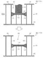
- FIG. 4 The figure which shows the 4th process (S4) and 5th process (S5) of the panel processing method in Embodiment 2.
- FIG. The figure which shows the 4th process (S4) and 5th process (S5) of the panel processing method in Embodiment 3.
- FIG. The figure which shows the 3rd process (S3) and 4th process (S4) of the panel processing method in Embodiment 4.
- FIG. 1 The figure which shows the 4th process (S4) and 5th process (S5) of the panel processing method in Embodiment 2.
- FIG. 4 The figure which shows the 4th process (S4) and 5th process (S5) of the panel processing method in Embodiment 3.
- FIG. The figure which shows the 3rd process (S3) and 4th process (S4) of the panel processing method in Embodiment 4.
- Embodiment 1 FIG. A mode in which the sealing process is performed on the panel using the honeycomb core will be described with reference to FIGS.
- FIG. 1 and 2 are cross-sectional views of the panel 100.
- FIG. 1 and 2 are cross-sectional views of the panel 100.
- the panel 100 is a plate including a honeycomb core 101 and two skin materials 102, and the honeycomb core 101 is sandwiched between the skin materials 102.
- the honeycomb core 101 is configured by arranging a plurality of polygonal columns (for example, hexagonal columns). Each polygonal column has a cylindrical shape.
- the skin material 102 is bonded to the upper and lower portions of the honeycomb core 101 by an adhesive sheet.
- the specific skin material 102 is aluminum or CFRP (Carbon Fiber Reinforced Plastic).
- the adhesive sheet is a sheet-like adhesive.
- the panel 100 is provided with a buried hole 103 by drilling using a drill or the like.
- the embedding hole 103 is a hole for embedding a component called an insert.
- the depth of the embedded hole 103 is shallower than the thickness of the panel 100. For example, the depth of the embedding hole 103 is about half of the thickness of the panel 100.
- the panel 100 is a honeycomb sandwich panel used for a structure such as an artificial satellite, a flying body, or an in-vehicle shelter.
- two plates of a bottom plate 111 and a push plate 112 are placed on the bottom of the embedding hole 103 so as to overlap each other.
- the gap between the two plates and the wall 104 of the honeycomb core 101 is closed by the sealant 113 protruding between the two plates.
- the closing process is an operation of closing a gap between the side portion of the bottom plate 111 and the plane of the honeycomb core 101.
- the n-th step in the sealing process is referred to as “Sn”.
- n is an integer.
- the fixing process is an operation for fixing the insert 120 to the embedded hole 103.
- the n-th step in the fixing processing procedure is denoted as “Fn”.
- FIG. 3 shows the first step (S1) and the second step (S2) of the sealing process.
- the bottom plate 111 is placed on the bottom of the embedding hole 103.
- a gap is generated between the side portion of the bottom plate 111 and the wall surface 105 of the honeycomb core 101.
- the bottom plate 111 is preferably a thin, light and durable material.
- the bottom plate 111 is a plate made of GFRP (Glass Fiber Reinforced Plastics).
- the plane of the bottom plate 111 has a shape and a size that match the entrance of the embedding hole 103. For example, if the inlet of the embedding hole 103 is circular, the plane of the bottom plate 111 is circular. Further, if the diameter of the entrance of the embedding hole 103 is 1 cm (centimeter), the diameter of the plane of the bottom plate 111 is 1 cm or slightly shorter than 1 cm.
- a sealant 113 is applied to the upper surface of the bottom plate 111.
- the sealant 113 is an adhesive for closing a gap between the side portion of the bottom plate 111 and the wall surface of the honeycomb core 101.
- the sealant 113 is a cyanoacrylate adhesive or an acrylic adhesive.
- the sealant 113 is a hybrid type adhesive in which a cyanoacrylate adhesive and an acrylic adhesive are mixed.
- an instantaneous adhesive that hardens immediately may be used as the sealant 113. This is because the time required for curing is shortened to shorten the time required for processing the panel 100. However, the time until the sealant 113 is cured is longer than the time required to perform the subsequent fifth step (S5).
- FIG. 4 shows the third step (S3) and the fourth step (S4) of sealing.
- the push plate 112 is placed on the sealant 113 applied to the upper surface of the bottom plate 111.
- the push plate 112 is preferably made of a thin, light and strong material, like the bottom plate 111.
- the plane of the push plate 112 has a shape and a size that match the entrance of the embedding hole 103, similarly to the plane of the bottom plate 111.
- the push plate 112 is the same plate as the bottom plate 111.
- the bar 114 is inserted into the embedding hole 103.
- FIG. 5 shows a fifth step (S5) of the sealing process.
- the push plate 112 is pushed by the bar 114.
- the pressing plate 112 is pressed against the sealing agent 113 applied to the upper surface of the bottom plate 111.
- the sealing agent 113 protrudes into the gap between the side portion of the bottom plate 111 and the wall surface 105 of the honeycomb core 101. As a result, the gap is closed with the sealant 113.
- FIG. 6 shows the first step (F1) and the second step (F2) of the fixing process.
- an adhesive for temporary fixing is applied to the upper surface of the pressing plate 112, and the insert 120 is embedded in the embedded hole 103.
- the insert 120 is a metal component that serves as an interface for connecting a component such as a structural member or a mounted device to the panel 100.
- An injection hole 121 for injecting the filler 122 is provided in the upper part of the insert 120.
- the top plane of the insert 120 has the same shape and size as the plane of the bottom plate 111 according to the entrance of the embedding hole 103.
- the lower plane of the insert 120 has a shape and a size different from the entrance of the embedding hole 103. However, the lower plane of the insert 120 is smaller than the entrance of the embedding hole 103.
- the adhesive for temporary fixing is an adhesive for temporarily fixing the insert 120.
- the temporary fixing adhesive is the same type of adhesive as the sealing agent 113.
- the tip of the syringe 130 containing the filler 122 is inserted into the injection hole 121.
- the filler 122 is an adhesive for fixing the insert 120 to the embedded hole 103.
- the filler 122 is a two-component epoxy adhesive using a high-viscosity main agent and a low-viscosity curing agent.
- FIG. 7 shows a third step (F3) of the fixing process.
- the filler 122 is injected from the syringe 130 into the embedding hole 103.
- the filler 122 is filled into the embedded hole 103.
- the insert 120 is fixed to the embedding hole 103 when the filler 122 is cured. Since the gap between the side portion of the bottom plate 111 and the side surface of the honeycomb core 101 is closed by the filler 113, the filler 122 is not filled below the bottom plate 111.
- Embodiment 1 *** Effects of Embodiment 1 *** It becomes possible to close the gap between the side portion of the bottom plate 111 and the wall surface of the honeycomb core 101. As a result, since the filler 122 is not filled below the bottom plate 111, the amount of the filler 122 to be filled is reduced. Therefore, the panel 100 can be reduced in weight.
- Embodiment 1 in order to close the gap between the side portion of the bottom plate 111 and the wall surface of the honeycomb core 101 with the sealant 113, the pressing plate 112 is pressed against the sealant 113 applied to the upper surface of the bottom plate 111.
- the sealant 113 is protruded into the gap. That is, if the pressing plate 112 is pressed against the sealant 113, the gap can be closed, so that the operation is very easy.
- the time required for the sealing process can be shortened.
- Embodiment 2 With respect to the form in which the pressing plate is pressed against the sealant with an insert instead of a bar, the difference from the first embodiment will be mainly described with reference to FIG.
- FIG. 8 shows the fourth step (S4) and the fifth step (S5) of the sealing process.
- the fourth step (S ⁇ b> 4) the temporary fixing adhesive 115 is applied to the upper surface of the pressing plate 112, and the insert 120 is placed on the temporary fixing adhesive 115.
- the insert 120 is pushed into the embedding hole 103. That is, the insert 120 is embedded in the embedding hole 103.
- the pressing plate 112 is pressed against the sealing agent 113 applied to the upper surface of the bottom plate 111.
- the sealing agent 113 protrudes into the gap between the side portion of the bottom plate 111 and the wall surface 105 of the honeycomb core 101. As a result, the gap is closed with the sealant 113.
- the fixing process procedure is the same as in the first embodiment.
- Embodiment 3 With respect to the form in which the pressing plate attached to the bottom surface of the insert is pressed against the sealant, differences from the first embodiment will be mainly described with reference to FIG.
- FIG. 9 shows the fourth step (S4) and the fifth step (S5).
- the push plate 112 is attached to the bottom surface of the insert 120, and the insert 120 is placed on the sealant 113 applied to the top surface of the bottom plate 111.
- the insert 120 is pushed into the embedding hole 103. That is, the insert 120 is embedded in the embedding hole 103.
- the pressing plate 112 is pressed against the sealing agent 113 applied to the upper surface of the bottom plate 111.
- the sealing agent 113 protrudes into the gap between the side portion of the bottom plate 111 and the wall surface 105 of the honeycomb core 101. As a result, the gap is closed with the sealant 113.
- the fixing process procedure is the same as in the first embodiment.
- Embodiment 4 With respect to the form of pressing the bottom of the insert against the sealant as a pressing plate, differences from the first embodiment will be mainly described with reference to FIG.
- FIG. 10 shows the third step (S3) and the fourth step (S4).
- the insert 120 is placed on the sealant 113 applied to the upper surface of the bottom plate 111.
- the bottom surface of the insert 120 has a shape and a size that match the entrance of the embedded hole 103.
- the insert 120 is pushed into the embedding hole 103. That is, the insert 120 is embedded in the embedding hole 103.
- the bottom of the insert 120 is pressed as a pressing plate against the filler 113 applied to the upper surface of the bottom plate 111.
- the sealing agent 113 protrudes into the gap between the side portion of the bottom plate 111 and the wall surface 105 of the honeycomb core 101. As a result, the gap is closed with the sealant 113.
- the fixing process procedure is the same as in the first embodiment.
- the procedure of the panel processing method may be performed by either a person or a machine. That is, an operator may perform each process of a panel processing method, and a panel processing apparatus may perform each process of a panel processing method. Moreover, the procedure of the panel processing method may be performed by a person and a machine. That is, the worker may perform a part of the process and the panel processing apparatus may perform the remaining process.
- the panel processing apparatus is an apparatus created for processing the panel 100 by the panel processing method.
- the embodiment is an example of a preferred embodiment and is not intended to limit the technical scope of the present invention.
- the embodiment may be implemented partially or in combination with other embodiments.
- the procedure of the panel processing method may be changed as appropriate.
Landscapes
- Engineering & Computer Science (AREA)
- General Engineering & Computer Science (AREA)
- Mechanical Engineering (AREA)
- Laminated Bodies (AREA)
- Adhesives Or Adhesive Processes (AREA)
- Standing Axle, Rod, Or Tube Structures Coupled By Welding, Adhesion, Or Deposition (AREA)
- Application Of Or Painting With Fluid Materials (AREA)
- Panels For Use In Building Construction (AREA)
Abstract
L'invention concerne une plaque de base (111) tout d'abord placée dans une partie inférieure d'un trou d'intégration (103) disposé dans une âme nid d'abeilles (101). Une charge (113) pour bloquer des espaces entre des parties latérales de la plaque de base et des surfaces de paroi de l'âme nid d'abeilles est ensuite appliquée sur une surface supérieure de la plaque de base. Une plaque de poussée (112) est ensuite poussée contre la charge. Ce faisant, la charge pénètre dans les espaces, et les espaces sont bloqués par la charge.
Priority Applications (4)
| Application Number | Priority Date | Filing Date | Title |
|---|---|---|---|
| ES16922840T ES2915326T3 (es) | 2016-12-01 | 2016-12-01 | Método de tratamiento de paneles |
| PCT/JP2016/085784 WO2018100721A1 (fr) | 2016-12-01 | 2016-12-01 | Procédé de traitement de panneau, panneau et dispositif de traitement de panneau |
| EP16922840.0A EP3549756B1 (fr) | 2016-12-01 | 2016-12-01 | Procédé de traitement de panneau |
| JP2018553609A JP6570770B2 (ja) | 2016-12-01 | 2016-12-01 | パネル加工方法、パネルおよびパネル加工装置 |
Applications Claiming Priority (1)
| Application Number | Priority Date | Filing Date | Title |
|---|---|---|---|
| PCT/JP2016/085784 WO2018100721A1 (fr) | 2016-12-01 | 2016-12-01 | Procédé de traitement de panneau, panneau et dispositif de traitement de panneau |
Publications (1)
| Publication Number | Publication Date |
|---|---|
| WO2018100721A1 true WO2018100721A1 (fr) | 2018-06-07 |
Family
ID=62241281
Family Applications (1)
| Application Number | Title | Priority Date | Filing Date |
|---|---|---|---|
| PCT/JP2016/085784 Ceased WO2018100721A1 (fr) | 2016-12-01 | 2016-12-01 | Procédé de traitement de panneau, panneau et dispositif de traitement de panneau |
Country Status (4)
| Country | Link |
|---|---|
| EP (1) | EP3549756B1 (fr) |
| JP (1) | JP6570770B2 (fr) |
| ES (1) | ES2915326T3 (fr) |
| WO (1) | WO2018100721A1 (fr) |
Cited By (1)
| Publication number | Priority date | Publication date | Assignee | Title |
|---|---|---|---|---|
| CN115722421A (zh) * | 2022-10-24 | 2023-03-03 | 无锡中卓智能科技股份有限公司 | 一种用于自动拼装组合注浆机的v形治具座架 |
Citations (5)
| Publication number | Priority date | Publication date | Assignee | Title |
|---|---|---|---|---|
| JPH11348155A (ja) * | 1998-06-02 | 1999-12-21 | Fuji Heavy Ind Ltd | ハニカムサンドイッチパネルへのインサート取付方法 |
| JPH11348157A (ja) * | 1998-06-02 | 1999-12-21 | Fuji Heavy Ind Ltd | ハニカムサンドイッチパネルへのインサート取付方法 |
| JP2000215929A (ja) * | 1999-01-26 | 2000-08-04 | Mitsubishi Electric Corp | 接地用インサ―ト |
| JP2001140362A (ja) | 1999-11-17 | 2001-05-22 | Mitsubishi Electric Corp | インサート充填方法 |
| WO2014121105A1 (fr) * | 2013-01-31 | 2014-08-07 | B/E Aerospace, Inc. | Insert et procédé pour ancrage dans un panneau à âme |
Family Cites Families (5)
| Publication number | Priority date | Publication date | Assignee | Title |
|---|---|---|---|---|
| DE2736132C2 (de) * | 1977-08-11 | 1981-12-17 | Messerschmitt-Bölkow-Blohm GmbH, 8000 München | Verfahren zum Herstellen von Sandwichbauteilen |
| DE2834237C2 (de) * | 1978-08-04 | 1980-05-22 | Messerschmitt-Boelkow-Blohm Gmbh, 8000 Muenchen | Verfahren zum Einbauen von Einsätzen in Leichtbau-Sandwichplatten |
| US5713706A (en) * | 1995-12-19 | 1998-02-03 | Shur-Lok Corporation | Plastic composite fastener for self-cutting and frictional welding |
| US7981519B2 (en) * | 2008-04-11 | 2011-07-19 | United Technologies Corporation | Metallic doubler for repair of a gas turbine engine part |
| PT3339659T (pt) * | 2013-03-20 | 2022-03-29 | Ruag Schweiz Ag | Peça de inserção para aplicação de carga e/ou ancoragem de vários componentes respetivamente num painel sanduíche composto e método de produção de uma estrutura leve de suporte compreendendo o mesmo |
-
2016
- 2016-12-01 WO PCT/JP2016/085784 patent/WO2018100721A1/fr not_active Ceased
- 2016-12-01 EP EP16922840.0A patent/EP3549756B1/fr active Active
- 2016-12-01 ES ES16922840T patent/ES2915326T3/es active Active
- 2016-12-01 JP JP2018553609A patent/JP6570770B2/ja active Active
Patent Citations (5)
| Publication number | Priority date | Publication date | Assignee | Title |
|---|---|---|---|---|
| JPH11348155A (ja) * | 1998-06-02 | 1999-12-21 | Fuji Heavy Ind Ltd | ハニカムサンドイッチパネルへのインサート取付方法 |
| JPH11348157A (ja) * | 1998-06-02 | 1999-12-21 | Fuji Heavy Ind Ltd | ハニカムサンドイッチパネルへのインサート取付方法 |
| JP2000215929A (ja) * | 1999-01-26 | 2000-08-04 | Mitsubishi Electric Corp | 接地用インサ―ト |
| JP2001140362A (ja) | 1999-11-17 | 2001-05-22 | Mitsubishi Electric Corp | インサート充填方法 |
| WO2014121105A1 (fr) * | 2013-01-31 | 2014-08-07 | B/E Aerospace, Inc. | Insert et procédé pour ancrage dans un panneau à âme |
Cited By (1)
| Publication number | Priority date | Publication date | Assignee | Title |
|---|---|---|---|---|
| CN115722421A (zh) * | 2022-10-24 | 2023-03-03 | 无锡中卓智能科技股份有限公司 | 一种用于自动拼装组合注浆机的v形治具座架 |
Also Published As
| Publication number | Publication date |
|---|---|
| JPWO2018100721A1 (ja) | 2019-04-11 |
| EP3549756A1 (fr) | 2019-10-09 |
| EP3549756A4 (fr) | 2019-12-04 |
| ES2915326T3 (es) | 2022-06-21 |
| EP3549756B1 (fr) | 2022-05-04 |
| JP6570770B2 (ja) | 2019-09-04 |
Similar Documents
| Publication | Publication Date | Title |
|---|---|---|
| KR20160002715A (ko) | 경량 지지 구조물과, 경량 지지 구조물 제작 방법, 복합 샌드위치 패널 및 복합 샌드위치 패널 제작 방법 | |
| ES2909604T3 (es) | Inserto para la aplicación de cargas y/o el anclaje de varios componentes en, respectivamente, un tablero tipo sandwich composite y procedimiento de producción de una estructura de soporte ligera que comprende el mismo | |
| US9079365B2 (en) | Curable assembly and a filler component | |
| ATE494131T1 (de) | Vorrichtung und verfahren zur herstellung von faserverstärkten verbundstrukturen | |
| JP6204093B2 (ja) | 補強構造体の製造方法 | |
| WO2014154207A1 (fr) | Agencement structural et procédé pour fixer un échafaudage sur un mur de bâtiment | |
| JP6570770B2 (ja) | パネル加工方法、パネルおよびパネル加工装置 | |
| EP3069858A1 (fr) | Procédé et dispositif de fabrication d'un composant d'éolienne en matériau en fibres composites | |
| KR101079318B1 (ko) | 고강도 섬유판을 이용한 조적벽이 포함된 철근 콘크리트 구조물의 내진보강공법 | |
| DE102014216007B4 (de) | Verfahren zum Herstellen einer Bauteilverbindung | |
| AU2015398068B2 (en) | Construction method for reinforcing a column and reinforcing structure for a column | |
| JP3988062B2 (ja) | コンクリート構造物の補強方法及び補強装置 | |
| KR101453214B1 (ko) | 복합소재 구조물 및 그 제조방법 | |
| WO2019025553A1 (fr) | Structure sandwich à élément de liaison noyé | |
| JP3627931B2 (ja) | コンクリート表面の補修構造およびコンクリート表面の補修方法 | |
| DE102014215547A1 (de) | Klebehalter zur Befestigung an einer Struktur | |
| EP3146156B1 (fr) | Élément de protection destiné à être relié à un élément en béton d'une construction de tunnel présentant un drainage | |
| JP2024058655A (ja) | ワンアップ組立のための方法および構造隙間充填材 | |
| EP3377827A1 (fr) | Support destiné à l'agencement d'une surface miroir d'un héliostat et procédé de fabrication d'un héliostat | |
| JP6474071B2 (ja) | 接着剤を用いる耐震補強方法及び耐震補強建築物 | |
| JP6826510B2 (ja) | 鉄骨梁接合用仮支持部材及び鉄骨梁の接合方法 | |
| JP2017179719A (ja) | 受圧構造体及び受圧構造体の施工方法 | |
| JP2017002549A (ja) | 柱の補強工法および柱の補強構造 | |
| DE102016002835A1 (de) | Dübel zur Befestigung von Schrauben oder dergleichen in Gebäudeteilen | |
| EP3124697A1 (fr) | Dispositif a inserer dans un composant compose d'une masse de type mortier durcissable |
Legal Events
| Date | Code | Title | Description |
|---|---|---|---|
| ENP | Entry into the national phase |
Ref document number: 2018553609 Country of ref document: JP Kind code of ref document: A |
|
| 121 | Ep: the epo has been informed by wipo that ep was designated in this application |
Ref document number: 16922840 Country of ref document: EP Kind code of ref document: A1 |
|
| NENP | Non-entry into the national phase |
Ref country code: DE |
|
| ENP | Entry into the national phase |
Ref document number: 2016922840 Country of ref document: EP Effective date: 20190701 |