WO2018105363A1 - 布類展張装置 - Google Patents
布類展張装置 Download PDFInfo
- Publication number
- WO2018105363A1 WO2018105363A1 PCT/JP2017/041613 JP2017041613W WO2018105363A1 WO 2018105363 A1 WO2018105363 A1 WO 2018105363A1 JP 2017041613 W JP2017041613 W JP 2017041613W WO 2018105363 A1 WO2018105363 A1 WO 2018105363A1
- Authority
- WO
- WIPO (PCT)
- Prior art keywords
- cloth
- chucks
- chuck
- clamp
- pair
- Prior art date
- Legal status (The legal status is an assumption and is not a legal conclusion. Google has not performed a legal analysis and makes no representation as to the accuracy of the status listed.)
- Ceased
Links
Images


Classifications
-
- D—TEXTILES; PAPER
- D06—TREATMENT OF TEXTILES OR THE LIKE; LAUNDERING; FLEXIBLE MATERIALS NOT OTHERWISE PROVIDED FOR
- D06C—FINISHING, DRESSING, TENTERING OR STRETCHING TEXTILE FABRICS
- D06C3/00—Stretching, tentering or spreading textile fabrics; Producing elasticity in textile fabrics
-
- D—TEXTILES; PAPER
- D06—TREATMENT OF TEXTILES OR THE LIKE; LAUNDERING; FLEXIBLE MATERIALS NOT OTHERWISE PROVIDED FOR
- D06F—LAUNDERING, DRYING, IRONING, PRESSING OR FOLDING TEXTILE ARTICLES
- D06F67/00—Details of ironing machines provided for in groups D06F61/00, D06F63/00, or D06F65/00
- D06F67/04—Arrangements for feeding or spreading the linen
Definitions
- the present invention relates to a cloth spreading device used for spreading cloths washed in a cloth washing factory or the like one by one in order to put them into an iron roller (also called a roll irona).
- a pair of input chucks are mounted on the cloth by attaching the adjacent corners of the washed cloth directly from the operator or via the cloth supply device at the lowered position.
- receive the adjacent corners of the cloth from the feeding chuck and then traverse to the positions separated from each other and pull the adjacent corners
- the fabric is stretched by the intermediate moving body, and the upper end of the fabric stretched from the stretch chuck at the forward position is received on the upper surface of the front part and held by suction, and then the negative pressure is stopped while moving to the retracted position.
- the cloth is delivered to the front part of the belt conveyor, and the belt conveys the stretched cloth received by the belt conveyor toward the ironing roller.
- the intermediate moving body holds the upper end portion of the cloth with a negative pressure that acts on the upper surface of the front portion.
- a swinging clamp provided on the upper surface of the front of the vacuum box is opened and closed, and the negative pressure that the vacuum box acts on the upper surface of the front and the swinging clamp
- holding the upper end of the fabric was also considered, and as a result, a certain effect was obtained, but the holding was still not sufficient, and the upper end of the fabric was shifted during the holding and moved to the belt conveyor at a predetermined position. It could not be handed over and there was room for improvement.
- the cloth stretcher according to the present invention advantageously solves the problems of the conventional cloth stretcher as described above, and the cloth stretcher according to the present invention includes a pair of closing chucks that grip adjacent corners of the washed cloth.
- a lifting device that moves the pair of input chucks up and down, a pair of extension chucks that receive cloth from the input chuck at the raised position of the pair of input chucks and grip adjacent corners of the cloth, and the pair A traverse device for traversing the stretch chuck, an intermediate moving body for holding the upper end of the cloth on the upper surface, an advancing / retreating device for moving the intermediate moving body forward and backward, and a belt conveyor for carrying out the stretched cloth.
- the pair of throwing chucks are mounted with the adjacent corners of the washed cloths in the lowered position to raise the cloths to the traversing position of the stretching chucks, and the pair of stretching chucks are moved closer to each other.
- the cloth After traversing and receiving the adjacent corners of the cloth from the input chuck, the cloth is expanded by traversing to a position away from each other and pulling the adjacent corners, and the intermediate moving body is in the forward position.
- the upper end of the cloth stretched from the stretch chuck is received and held on the upper surface, and then the cloth is transferred to the front portion of the belt conveyor by releasing the upper end of the cloth while moving to the retracted position.
- the intermediate moving body is A rearward surface descending from the front to the step between the front portion of the upper surface and the lower step portion; Then a clamp facing the facing surface, A clamp driving device for moving the clamp forward and backward with respect to the rearward surface to sandwich and release the upper portion of the cloth between the clamp and the rearward surface; It is characterized by having.
- the pair of input chucks are mounted at the lowered position on the adjacent corners of the washed cloth to raise the cloth to the traverse position of the spreading chuck,
- the stretch chuck traverses to a position approaching each other, receives adjacent corners of the cloth from the input chuck, then traverses to a position away from each other and pulls the adjacent corners to stretch the cloth, and move intermediately.
- the upper end of the fabric stretched from the stretch chuck at the forward position is received and held on the upper surface, and then the fabric is transferred to the front of the belt conveyor by releasing the upper end of the fabric while moving to the retracted position. Then, the belt conveys the stretched cloth received.
- the clamp driving device moves the clamp backward with respect to the rearward surface and separates it in advance.
- the clamp is moved forward, and the upper end portion of the cloth is sandwiched between the clamp and the rearward facing surface.
- the tensile force applied to the upper end portion from the portion below the upper end portion of the cloth changes in the direction of the rearward surface and the front portion and the rearward direction. It is weakened by the friction of the corners with the surface, so that the clamp securely holds the upper end of the fabric against the rearward surface.
- the received cloth is sufficiently removed when a particularly heavy cloth is delivered or when the operation speed is increased in order to increase the supply efficiency to the ironing roller. It can be held and reliably delivered to the belt conveyor at a predetermined position.
- the clamp driving device may swing the intermediate moving body with respect to the rearward surface to move forward and backward.
- the intermediate moving body is preferably moved linearly with respect to the rearward surface. In this way, the height of the clamp and the clamp drive device protruding from the upper surface of the intermediate moving body can be reduced, so that the configuration of the cloth spreading device can be made compact in the height direction.
- the intermediate moving body holds the upper end of the cloth on the upper surface with negative pressure acting on the upper surface from the inside in addition to the rearward surface and the clamp. And preferred. If it does in this way, the received cloth can be held more firmly and it can be more reliably delivered to a belt conveyor at a predetermined position.
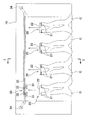
- the cloth spreading apparatus A is an apparatus for suspending the cloth C, forming it into a rectangular shape that is neatly stretched into a quadrangle, and putting it into a roll ironer or the like as a processing apparatus for the next process.
- the cloth C handled by this apparatus is after washing and drying, before ironing, and has a square shape. This square includes both square and rectangular shapes. Examples of such cloth C include sheets, futon wrapping, and towels.
- reference numeral 10 denotes an apparatus main body, and a loading unit 20 is provided on the front surface thereof.
- the input unit 20 includes a pair of input chucks 21 and 21 that grip both corners of one side of the cloth C, a chuck base 22 to which the input chucks 21 and 21 are fixed, and an elevating device 23 that moves the chuck base 22 up and down. And.
- the pair of input chucks 21 and 21 can be moved up and down by the lifting device 23.
- the chuck base 22 has a width about the width of a person's shoulder, and input chucks 21 and 21 are provided at both left and right ends thereof.
- Each input chuck 21 is composed of two chucks arranged on the left and right sides with a predetermined interval.
- the lifting device 23 raises the cloth C together with the input chucks 21, 21, and the cloth C is put on the stretcher 30 described later. Deliver C.
- the cloth spreading device A is provided with one or a plurality of input units 20.
- four input units 20 are provided, and the cloth C can be input from any of the input units 20.
- the elevating device 23 is driven by an actuator capable of speed / position control.
- Actuators capable of speed / position control include servo actuators such as servo motors and servo cylinders, stepping motors, and the like.
- the lifting device 23 of the present embodiment includes a rod 23a that guides the chuck base 22 to move up and down, an endless belt 23b that is disposed along the rod 23a and fixed to the chuck base 22, and is wound around the endless belt 23b. And a servo motor 23c that drives the pulley to rotate forward and reverse.
- the stretch portion 30 includes a pair of stretch chucks 31 and 31 that grip both corners of one side of the cloth C, a pair of carriages 32 and 32 to which the stretch chuck 31 is fixed, and the carriages 32 and 32 are horizontally moved.
- the rail 33 which guides so that it may move, and the traversing apparatus 34 which can move each carriage 32 separately are provided.
- the traversing device 34 is composed of, for example, a combination of a servo motor and an endless belt.
- the traversing device 34 can traverse the pair of spreading chucks 31, 31 individually.
- the traversing device 34 is not limited to a servo motor, and may be configured to be driven by another actuator capable of speed / position control.
- the spreading chuck 31 When the cloth C is raised by the operation of the loading unit 20, the spreading chuck 31 receives the cloth C from the loading chuck 21 and grips the corners. At this time, each spreading chuck 31 passes between two chucks constituting each input chuck 21. Therefore, the cloth C can be delivered without the spread chuck 31 and the input chuck 21 interfering with each other. Thereafter, the cloth C can be spread and hung by traversing the pair of spreading chucks 31, 31 so as to open to the left and right.
- a delivery unit 40 is disposed below the extension unit 30.
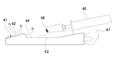
- the transfer unit 40 is a vacuum box 41 as an intermediate moving body that sucks and holds the upper edge of the cloth C when negative pressure is applied, an air cylinder or a servo motor as an advance / retreat device that moves the vacuum box 41 forward and backward (Not shown).
- the vacuum box 41 has a front part 42 inclined slightly forward on the upper surface and a step part 43 that is one step lower than the front part 42 behind the front part 42 and slightly between them. It has a rear surface 44 inclined upward (for example, about 30 degrees from the vertical), and further has an air cylinder 45 as a clamp driving device on the upper surface behind the stepped portion 43, and this air cylinder 45 has its piston rod. It is possible to support the clamp 46 made of an elastic body at the front end portion thereof and to move the clamp 46 forward and backward with respect to the rearward surface 44 by the forward and backward movement of the piston rod.
- the vacuum box 41 also has a negative pressure generator 47 such as a blower for generating a negative pressure in the vacuum box 41 at its rear end, and the negative pressure generated by the negative pressure generator 47 is applied to the front portion 42 on the upper surface.
- a negative pressure generator 47 such as a blower for generating a negative pressure in the vacuum box 41 at its rear end, and the negative pressure generated by the negative pressure generator 47 is applied to the front portion 42 on the upper surface.
- the large number of small holes h provided in the stepped portion 43 and the rearward facing surface 44 can affect the upper surface.
- a primary conveyor 50 including a belt conveyor is disposed below the delivery unit 40.
- the primary conveyor 50 includes a conveyor belt 51 having a large number of small holes, and a vacuum box 52 disposed below the conveying surface. While the cloth C is sucked by the primary conveyor 50, it can be fed backward.
- a secondary conveyor 60 composed of a belt conveyor is connected to the rear of the primary conveyor 50 so that the cloth C can be fed to a processing apparatus for the next process, for example, a roll ironer.
- An airflow shaping unit 11 is formed in the lower front portion of the apparatus body 10.
- the lower part of the airflow shaping unit 11 is connected to the blower 13 through the duct 12.
- a second duct 14 is formed on the back surface of the airflow shaping unit 11.
- the duct 14 is configured to communicate the vacuum box 52 of the primary conveyor 50 and the blower 13.
- An opening / closing plate 15 is provided between the ducts 12 and 14 and the blower 13. The opening / closing plate 15 selectively opens and closes the opening of the duct 12 and the opening of the duct 14. Therefore, the state can be selectively switched between a state in which air is sucked into the airflow shaping unit 11 from the front surface of the apparatus main body 10 and a state in which the vacuum box 52 of the primary conveyor 50 is operated.
- the cloth spreading device A includes a control device 70 that controls the operations of the lifting device 23 and the traversing device 34.
- the control device 70 is a computer configured with a CPU, a memory, and the like. By controlling the operation of the elevating device 23 and the traversing device 34 by the control device 70, the closing chuck 21 and the spreading chuck 31 can be operated in synchronization. Details thereof will be described later.
- the loading chuck 21 stands by at the lowered loading position. An operator searches for the corners on both sides of one side of the cloth C, and causes the input chucks 21 and 21 to grip each of them.
- the input chucks 21 and 21 are waiting at the input position a lowered.
- the stretch chucks 31 and 31 are in a standby state after the operation of the other fabric C is being performed or after the operation is completed.
- the spreading chuck 31 is waiting at the position where the cloth C is left and right (the position shown in FIG. 8A) or at a predetermined standby position. The operator finds both corners of one side of the cloth C, and causes the input chucks 21 and 21 to grip each of the corners.
- control device 70 operates the lifting device 23 and the traversing device 34 simultaneously to raise the charging chuck 21 from the loading position a to the delivery position d.
- the spreading chuck 31 is traversed to the delivery position d.
- the input chuck 21 and the extension chuck 31 operate simultaneously.
- “simultaneous operation” means that the other is operating within the period in which one is operating, and the timing of starting and stopping the operation may not be the same.
- the cloth spreading device A is provided with four throwing parts 20, and the cloth C can be thrown from any of the throwing parts 20.
- the input chuck 21 includes two chucks arranged on the left and right sides with a predetermined interval, and the extension chuck 31 passes between the two chucks so that the extension chuck 31 and the input chuck are provided.
- Cloth 21 can be delivered without interfering with 21. Therefore, when the fabric C is delivered, the loading chuck 21 is operated so as to pass the delivery position d while being stopped at the delivery position d. Therefore, it is necessary that the spreading chuck 31 arrives at the delivery position d before the closing chuck 21. In such a case, the speed of the input chuck 21 and the extension chuck 31 may be adjusted so that the extension chuck 31 arrives at the transfer position d first, or temporarily before the input chuck 21 at the transfer position d. You may make it stop.
- control device 70 operates the lifting device 23 and the traversing device 34 simultaneously to raise the closing chucks 21, 21 from the delivery position d to the high position c, 31 is traversed left and right from the delivery position d.
- the cloth C is unfolded by spreading the pair of spreading chucks 31, 31 left and right.
- the making chuck 21 is lowered from the high position c to the making position a.
- the input chuck 21 and the extension chuck 31 operate simultaneously. Even in this case, it is only necessary that the other is operating within a period during which one is operating, and the timing of starting and stopping the operation may not be the same.
- the spread chuck 31 starts traversing after rising to a position where the input chuck 21 does not interfere. In general, since the traverse distance of the spreading chuck 31 is longer than the ascending distance of the feeding chuck 21, the spreading chuck 31 is traversed even after the feeding chuck 21 reaches the high position c and stops.
- the washed cloth can be spread and the cloth can be carried out to a roll irona or the like, and the vacuum box 41 delivers a particularly heavy cloth.
- the received fabric can be sufficiently held and reliably delivered to the primary conveyor 50 at a predetermined position.
- the clamp driving device is the air cylinder 45 that linearly moves the clamp 46 forward and backward with respect to the rearward surface 44. Therefore, the vacuum of the clamp 46 and the air cylinder 45 is reduced. Since the protrusion height from the upper surface of the box 41 can be reduced, the configuration of the fabric spreading device A can be made compact in the height direction.
- the vacuum box 41 is formed on the upper surface of the cloth C on the upper surface with negative pressure acting on the upper surface from the inside by the negative pressure generator 47 in addition to the rearward surface 44 and the clamp 46. Since the upper end portion is held, the received cloth can be more firmly held and delivered to the primary conveyor 50 more reliably at a predetermined position.
- the present invention has been described based on the illustrated examples, the present invention is not limited to the above-described examples, and can be appropriately changed within the scope of the claims. Instead of linearly moving back and forth with respect to the surface, it may be moved back and forth by swinging. Further, the rearward surface 44 can be set at an appropriate inclination angle and may be vertical.
- the received fabric is sufficiently retained, especially when delivering heavy fabrics or increasing the operating speed especially to increase the supply efficiency to the ironing roller.
- the received fabric can be reliably delivered to the belt conveyor at a predetermined position.
- a Cloth extension device C Cloth 10 Device body 20 Input portion 21 Input chuck 22 Chuck base 23 Lifting device 23a Rod 23b Endless belt 23c Servo motor 30 Extension portion 31 Extension chuck 32 Carriage 33 Rail 34 Traverse device 40 Delivery portion 41 Vacuum box 42 Front 43 Step 44 Backward 45 Air Cylinder 46 Clamp 47 Negative Pressure Generator 50 Primary Conveyor 60 Secondary Conveyor 70 Control Device
Landscapes
- Engineering & Computer Science (AREA)
- Textile Engineering (AREA)
- Treatment Of Fiber Materials (AREA)
Abstract
一対の投入チャックが布類の隣り合う角部を下降位置で装着されてその布類を展張チャックの横行位置まで上昇させ、一対の展張チャックが互いの接近位置へ横行して投入チャックから布類の隣り合う角部を受け取った後に互いの離間位置へ横行してその隣り合う角部を引っ張ることで布類を展張し、中間移動体が前進位置で展張チャックから展張した布類の上端部を受け取って保持した後に後退位置へ移動しながらその上端部を解放することで布類をベルトコンベヤに引き渡し、ベルトコンベヤがその展張状態の布類を搬出する布類展張装置において、中間移動体が、上面の前部とそれより低い段部との間で下降する後向き面と、その後向き面に対向するクランプと、そのクランプを後向き面に対し進退移動させてそのクランプと後向き面との間で布類の上部を挟持および解放するクランプ駆動装置とを有している。
Description
この発明は、布類洗濯工場等において洗濯された布類をアイロンローラ(ロールアイロナとも呼ばれる)に投入するために一枚ずつ広げる際に用いられる布類展張装置に関するものである。
従来の布類展張装置としては、例えば本願出願人が先に開示した特許文献1記載のものが知られており、この布類展張装置は、洗濯された布類の隣り合う角部を把持する一対の投入チャックと、その一対の投入チャックを昇降移動させる昇降装置と、一対の投入チャックの上昇位置でその投入チャックから布類を受け取って布類の隣り合う角部を把持する一対の展張チャックと、その一対の展張チャックを横行させる横行装置と、布類の上端部を上面上に保持する中間移動体と、その中間移動体を進退移動させる進退装置と、展張した布類を搬出するベルトコンベヤと、を具えている。
かかる従来の布類展張装置は、一対の投入チャックが、洗濯された布類の隣り合う角部を下降位置で作業者から直接あるいは布類供給装置を介して装着されてその布類を展張チャックの横行位置まで上昇させ、一対の展張チャックが互いに接近する位置へ横行して投入チャックから布類の隣り合う角部を受け取った後に互いに離間する位置へ横行してその隣り合う角部を引っ張ることで布類を展張し、中間移動体が前進位置で展張チャックから展張した布類の上端部を前部上面上に受け取って負圧で吸着保持した後に後退位置へ移動しながら負圧を止めて布類の上端部を解放することで布類をベルトコンベヤの前部に引き渡し、ベルトコンベヤがその受け取った展張状態の布類をアイロンローラに向けて搬出する。
ところで、上記従来の布類展張装置について本願発明者がさらに研究を進めたところ、この布類展張装置では、中間移動体が前部上面に作用させる負圧で布類の上端部を保持するので、特に重い布類を受け渡す場合や、アイロンローラへの供給効率を高めるために特に作動速度を速めた場合などに、受け取った布類を十分に保持して所定の位置で確実にベルトコンベヤに引き渡すことが難しいという課題があることが判明した。
そしてこの問題の解決のために、バキュームボックスの前部上面上に揺動式のクランプを設けたそれを開閉作動させ、バキュームボックスが前部上面上に作用させる負圧とその揺動式クランプとで布類の上端部を保持することも検討し、それによって一定の効果は得られたが、未だ保持が十分でなく、布類の上端部が保持中にずれて所定の位置でベルトコンベヤに引き渡すことができず、改良の余地があった。
この発明は、上述の如き従来の布類展張装置の課題を有利に解決するものであり、この発明の布類展張装置は、洗濯された布類の隣り合う角部を把持する一対の投入チャックと、その一対の投入チャックを昇降移動させる昇降装置と、一対の投入チャックの上昇位置でその投入チャックから布類を受け取って布類の隣り合う角部を把持する一対の展張チャックと、その一対の展張チャックを横行させる横行装置と、布類の上端部を上面上に保持する中間移動体と、その中間移動体を進退移動させる進退装置と、展張した布類を搬出するベルトコンベヤと、を具え、
前記一対の投入チャックが、洗濯された布類の隣り合う角部を下降位置で装着されてその布類を前記展張チャックの横行位置まで上昇させ、前記一対の展張チャックが、互いに接近する位置へ横行して前記投入チャックから布類の隣り合う角部を受け取った後に、互いに離間する位置へ横行してその隣り合う角部を引っ張ることで布類を展張し、前記中間移動体が前進位置で前記展張チャックから展張した布類の上端部を上面上に受け取って保持した後に後退位置へ移動しながら布類の上端部を解放することで布類を前記ベルトコンベヤの前部に引き渡し、前記ベルトコンベヤがその受け取った展張状態の布類を搬出する布類展張装置において、
前記中間移動体が、
上面の前部とそれより低い段部との間でその前部から段部に向かって下降する後向き面と、
その後向き面に対向するクランプと、
そのクランプを前記後向き面に対し進退移動させてそのクランプと前記後向き面との間で前記布類の上部を挟持および解放するクランプ駆動装置と、
を有することを特徴とするものである。
この発明の布類展張装置にあっては、一対の投入チャックが、洗濯された布類の隣り合う角部を下降位置で装着されてその布類を展張チャックの横行位置まで上昇させ、一対の展張チャックが互いに接近する位置へ横行して投入チャックから布類の隣り合う角部を受け取った後に互いに離間する位置へ横行してその隣り合う角部を引っ張ることで布類を展張し、中間移動体が前進位置で展張チャックから展張した布類の上端部を上面上に受け取って保持した後に後退位置へ移動しながら布類の上端部を解放することで布類をベルトコンベヤの前部に引き渡し、ベルトコンベヤがその受け取った展張状態の布類を搬出する。
そして、中間移動体が前進位置で展張チャックから展張した布類の上端部を上面上に受け取って保持する際には、クランプ駆動装置があらかじめクランプを後向き面に対し後退移動させて離間させておいて、布類の上端部が中間移動体の前部から少なくともその後向き面まで掛かるように載置されるとクランプを前進移動させ、そのクランプと後向き面とで布類の上端部を挟持する。このとき、中間移動体の上面の前部と後向き面とは角度が異なるので、布類の上端部よりも下の部分から上端部に加わる引っ張り力は後向き面で方向が変わるとともに前部と後向き面との間の角部の摩擦で弱められ、これによりクランプが、後向き面との間に布類の上端部を確実に挾持する。
従って、この発明の布類展張装置によれば、特に重い布類を受け渡す場合や、アイロンローラへの供給効率を高めるために特に作動速度を速めた場合などに、受け取った布類を十分に保持して所定の位置で確実にベルトコンベヤに引き渡すことができる。
なお、この発明の布類展張装置においては、前記クランプ駆動装置は、前記中間移動体を前記後向き面に対して揺動させて進退移動させるものであってもよいが、前記クランプ駆動装置は、前記中間移動体を前記後向き面に対して直線的に進退移動させるものであると好ましい。このようにすれば、クランプおよびクランプ駆動装置の中間移動体上面からの突出高さを小さくできるので、布類展張装置の構成を高さ方向にコンパクトにすることができる。
また、この発明の布類展張装置においては、前記中間移動体は、前記後向き面と前記クランプに加えて内部から上面に作用する負圧で上面上に布類の上端部を保持するものであると好ましい。このようにすれば、受け取った布類をより強固に保持して所定の位置でより確実にベルトコンベヤに引き渡すことができる。
以下に、本発明の実施形態を図面に基づき詳細に説明する。まず、図1および図2に基づき、布類展張装置Aの基本構造を説明する。
布類展張装置Aは、布類Cを吊り下げて四角形にきれいに引き伸ばした整形状態とし、次工程の処理装置であるロールアイロナ等に投入するための装置である。本装置で扱う布類Cは、洗濯、乾燥後のものであり、アイロン掛け前のものであり、形状は四角形である。この四角形には正方形のものも長方形のものも含まれる。なお、このような布類Cには、シーツや布団包布、タオル等を例示できる。
布類展張装置Aは、布類Cを吊り下げて四角形にきれいに引き伸ばした整形状態とし、次工程の処理装置であるロールアイロナ等に投入するための装置である。本装置で扱う布類Cは、洗濯、乾燥後のものであり、アイロン掛け前のものであり、形状は四角形である。この四角形には正方形のものも長方形のものも含まれる。なお、このような布類Cには、シーツや布団包布、タオル等を例示できる。
図中符号10は装置本体であり、その前面には投入部20が設けられている。投入部20は、布類Cの一辺の両端角部を把持する一対の投入チャック21、21と、それら投入チャック21、21が固定されたチャックベース22と、チャックベース22を昇降させる昇降装置23とを備えている。昇降装置23により一対の投入チャック21、21を昇降させることができる。チャックベース22は人の肩幅程度の幅を有しており、その左右両端に投入チャック21、21が設けられている。各投入チャック21は、所定間隔を有して左右に並べられた2つのチャックからなる。
洗濯、乾燥後の布類Cを作業者が手作業で投入チャック21、21に把持させると、昇降装置23は投入チャック21、21とともに布類Cを上昇させ、後述の展張部30に布類Cを受け渡す。
布類展張装置Aには、一または複数の投入部20が備えられている。本実施形態では、投入部20が4基設けられており、いずれの投入部20からでも布類Cを投入することができるようになっている。
本実施形態は、昇降装置23が速度・位置制御可能なアクチュエータで駆動される。「速度・位置制御可能なアクチュエータ」としては、サーボモータやサーボシリンダ等のサーボアクチュエータや、ステッピングモータ等が挙げられる。本実施形態の昇降装置23は、チャックベース22が上下動するように案内するロッド23aと、ロッド23aに沿って配置され、チャックベース22に固定された無端ベルト23bと、無端ベルト23bに巻回されたプーリーを正逆回転駆動するサーボモータ23cとで構成されている。
昇降装置23の上部位置には展張部30が設けられている。展張部30は、布類Cの一辺の両端角部を把持する一対の展張チャック31、31と、それぞれに展張チャック31が固定された一対のキャリッジ32、32と、キャリッジ32、32が左右に移動するように案内するレール33と、各キャリッジ32を個別に動かすことができる横行装置34とを備えている。横行装置34は、例えばサーボモータと無端ベルトとの組み合わせで構成されている。横行装置34により一対の展張チャック31、31を個別に横行させることができる。なお、横行装置34もサーボモータに限らず、他の速度・位置制御可能なアクチュエータで駆動されるように構成してもよい。
投入部20の動作により布類Cが上昇すると、展張チャック31は投入チャック21から布類Cを受け取り、その角部を把持する。この際、各展張チャック31は各投入チャック21を構成する2つのチャックの間を通過する。そのため、展張チャック31と投入チャック21とが互いに干渉することなく布類Cを受け渡すことができる。その後、一対の展張チャック31、31が左右に開くように横行することで、布類Cを広げて吊り下げることができる。
展張部30の下方には、受け渡し部40が配置されている。受け渡し部40は、負圧を作用させると布類Cの上端縁を吸引して保持する中間移動体としてのバキュームボックス41と、バキュームボックス41を進退移動させる進退装置としてのエアシリンダまたはサーボモータ等(図示せず)とを備えている。
バキュームボックス41は、図3に示すように、その上面に僅かに前向きに傾斜した前部42とその後方で前部42よりも一段下がった段部43とを有するとともに、それらの間に僅かに上向き(例えば鉛直から30度程度)に傾斜した後向き面44を有し、さらに段部43の後方の上面上にクランプ駆動装置としてのエアシリンダ45有しており、このエアシリンダ45はそのピストンロッドの先端部で弾性体からなるクランプ46を支持するとともに、そのピストンロッドの進退動作でクランプ46を後向き面44に対し進退移動させることができる。バキュームボックス41はまたその後端部に、バキュームボックス41内に負圧を生じさせるブロア等の負圧発生器47を有し、その負圧発生器47が生じさせた負圧を上面の前部42、段部43および後向き面44に設けた多数の小穴hから上面上に及ぼすことができる。
受け渡し部40の下方には、ベルトコンベヤからなる一次コンベア50が配置されている。一次コンベア50は、多数の小孔を有するコンベアベルト51と、その搬送面の下方に配置されたバキュームボックス52とを備えている。一次コンベア50により布類Cを吸引しつつ、後方に送り出せるようになっている。一次コンベア50の後方には、ベルトコンベヤからなる二次コンベア60が接続されており、次工程の処理装置、例えば、ロールアイロナに布類Cを送り込めるようになっている。
装置本体10の正面下方部分には、気流整形部11が形成されている。気流整形部11の下部はダクト12を通じてブロワー13に接続されている。気流整形部11の背面には第2のダクト14が形成されている。このダクト14は一次コンベア50のバキュームボックス52とブロワー13とを連通するように構成されている。ダクト12、14とブロワー13との間には開閉板15が備えられている。この開閉板15は、ダクト12の開口とダクト14の開口とを択一的に開放閉止するものである。したがって、装置本体10の前面から空気を気流整形部11内に吸引する状態と、一次コンベア50のバキュームボックス52を作動させる状態とで、択一的に切り替えることができる。
布類展張装置Aは、昇降装置23および横行装置34の動作を制御する制御装置70を備えている。制御装置70は、CPUやメモリ等で構成されたコンピュータである。この制御装置70により、昇降装置23および横行装置34の動作を制御することで、投入チャック21と展張チャック31を同期して動作させることができる。その詳細は後述する。
つぎに、図4から図7に基づき、布類展張装置Aの動作を説明する。
(I)投入作業
はじめに、投入チャック21は下降した投入位置で待機している。作業者が布類Cの一辺の両端角部を探し出し、それぞれを投入チャック21、21に把持させる。
(I)投入作業
はじめに、投入チャック21は下降した投入位置で待機している。作業者が布類Cの一辺の両端角部を探し出し、それぞれを投入チャック21、21に把持させる。
(II)展開動作
そうすると、投入チャック21が、投入位置から最も高い位置まで上昇する。その途中の、投入チャック21が展張チャック31と重なる受け渡し位置で、布類Cが投入チャック21から展張チャック31に受け渡される。そして、一対の展張チャック31、31が左右に広がり、布類Cを吊り下げて広げることで展開する。
そうすると、投入チャック21が、投入位置から最も高い位置まで上昇する。その途中の、投入チャック21が展張チャック31と重なる受け渡し位置で、布類Cが投入チャック21から展張チャック31に受け渡される。そして、一対の展張チャック31、31が左右に広がり、布類Cを吊り下げて広げることで展開する。
(III)引き込み動作
つぎに、開閉板15を切り替えて、空気を気流整形部11内に吸引する状態とすると、布類Cは気流整形部11内に負圧によって引き込まれる。
つぎに、開閉板15を切り替えて、空気を気流整形部11内に吸引する状態とすると、布類Cは気流整形部11内に負圧によって引き込まれる。
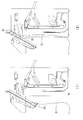
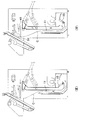
(IV)受け渡し動作
再び開閉板15を切り替えると、気流整形部11内の空気流は止まり、布類Cを引き上げやすい状態となる。この状態で、図4(a)に示すように、バキュームボックス41を前進させて布類Cに接触させるとともに、展張チャック31を開き、併せて例えば前方からエアブローを与えると、図4(b)に示すように、布類Cの上端部がバキュームボックス41の上面の前部42から段部43にかけて吸着され、ついで図4(c)に示すように、クランプ46がエアシリンダ45で駆動されて前進移動して、そのクランプ46と後向き面44との間に布類Cの上端部が挾持される。
再び開閉板15を切り替えると、気流整形部11内の空気流は止まり、布類Cを引き上げやすい状態となる。この状態で、図4(a)に示すように、バキュームボックス41を前進させて布類Cに接触させるとともに、展張チャック31を開き、併せて例えば前方からエアブローを与えると、図4(b)に示すように、布類Cの上端部がバキュームボックス41の上面の前部42から段部43にかけて吸着され、ついで図4(c)に示すように、クランプ46がエアシリンダ45で駆動されて前進移動して、そのクランプ46と後向き面44との間に布類Cの上端部が挾持される。
(V)乗り継ぎ動作
ついで図4(d)に示すように、バキュームボックス41を後進させながら布類Cの上部を一次コンベア50上に引き上げ、ついで図4(e)に示すように、クランプ46をエアシリンダ45で後向き面44に対し後退移動させて布類Cの上端部を解放すると、布類Cの上端部がバキュームボックス41から一次コンベア50に乗り継がれる。この際、一次コンベア50のバキュームボックス52は作動した状態にある。
ついで図4(d)に示すように、バキュームボックス41を後進させながら布類Cの上部を一次コンベア50上に引き上げ、ついで図4(e)に示すように、クランプ46をエアシリンダ45で後向き面44に対し後退移動させて布類Cの上端部を解放すると、布類Cの上端部がバキュームボックス41から一次コンベア50に乗り継がれる。この際、一次コンベア50のバキュームボックス52は作動した状態にある。
(VI)排出動作
ついで、布類Cは、一次コンベア50から二次コンベア60に移動して、次工程の処理装置に排出される。また、投入チャック21は投入位置まで下降する。
ついで、布類Cは、一次コンベア50から二次コンベア60に移動して、次工程の処理装置に排出される。また、投入チャック21は投入位置まで下降する。
次に、本実施形態の上記動作のうち、展開動作について詳細を図8から図10に基づき説明する。
(1)はじめに、投入チャック21、21は下降した投入位置aで待機している。一方、展張チャック31、31は、他の布類Cの展張動作中か、動作終了後の待機状態である。待機状態の場合、展張チャック31は、布類Cを左右に広げた状態のままの位置(図8(1)の位置)か、所定の待機位置で待機している。作業者は、布類Cの一辺の両端角部を探し出し、それぞれを投入チャック21、21に把持させる。
(2)投入チャック21に布類Cが把持されると、制御装置70は、昇降装置23および横行装置34を同時に動作させて、投入チャック21を投入位置aから受け渡し位置dまで上昇させるとともに、展張チャック31を受け渡し位置dまで横行させる。
(3)投入チャック21と展張チャック31がともに受け渡し位置dに到着すると、投入チャック21に把持されていた布類Cが、展張チャック31に受け渡される。
上記(2)から(3)の工程では、投入チャック21と展張チャック31が同時に動作する。ここで「同時に動作」とは、一方が動作している期間内に、他方が動作していればよく、動作の開始や停止のタイミングは同時でなくてもよい。
布類展張装置Aには4つの投入部20が備えられており、いずれの投入部20からでも布類Cを投入することができる。これら4つの投入部20に対して展張部30は一つであり、各投入部20に投入された布類Cを順に処理する。したがって、投入部20に布類Cを投入した時には、展張部30は他の投入部20に投入された布類Cの受け渡し動作中か、展張動作中である場合がある。このような場合、投入チャック21の上昇を先に開始して、展張チャック31の横行は他の布類Cの展張動作終了後に開始してもよい。
また、本実施形態では、投入チャック21は所定間隔を有して左右に並べられた2つのチャックからなり、展張チャック31はその2つのチャックの間を通過することで、展張チャック31と投入チャック21とが互いに干渉することなく布類Cを受け渡すことができる。そのため、布類Cの受け渡し時には、展張チャック31を受け渡し位置dで停止させた状態で、投入チャック21が受け渡し位置dを通過するよう動作させる。そのため、受け渡し位置dには、展張チャック31の方が投入チャック21よりも先に到着している必要がある。このような場合、投入チャック21および展張チャック31の速度を調整して展張チャック31の方が先に受け渡し位置dに到着するようにしてもよいし、投入チャック21を受け渡し位置dの手前で一時停止させるようにしてもよい。
(4)布類Cの受け渡し後、制御装置70は、昇降装置23および横行装置34を同時に動作させて、投入チャック21、21を受け渡し位置dから高位置cまで上昇させるとともに、展張チャック31、31を受け渡し位置dから左右に横行させる。
(5)一対の展張チャック31、31を左右に広げることで、布類Cを展開する。
(6)布類Cが展張チャック31から受け渡し部40に受け渡された後に、投入チャック21を高位置cから投入位置aまで下降させる。
(6)布類Cが展張チャック31から受け渡し部40に受け渡された後に、投入チャック21を高位置cから投入位置aまで下降させる。
上記(4)から(5)の工程においても、投入チャック21と展張チャック31が同時に動作する。この場合でも、一方が動作している期間内に、他方が動作していればよく、動作の開始や停止のタイミングは同時でなくてもよい。展張チャック31は投入チャック21が干渉しない位置まで上昇した後に横行を開始する。また、一般に、投入チャック21の上昇距離に対して展張チャック31の横行距離は長いので、投入チャック21が高位置cに達して停止した後も、展張チャック31は横行する。
従って、この実施形態の布類展張装置Aによれば、洗濯された布類を展張させてその布類をロールアイロナなどに搬出することができ、しかもバキュームボックス41が、特に重い布類を受け渡す場合や、ロールアイロナへの供給効率を高めるために特に作動速度を速めた場合などに、受け取った布類を十分に保持して所定の位置で確実に一次コンベヤ50に引き渡すことができる。
さらに、この実施形態の布類展張装置によれば、クランプ駆動装置は、クランプ46を後向き面44に対して直線的に進退移動させるエアシリンダ45であることから、クランプ46およびエアシリンダ45のバキュームボックス41の上面からの突出高さを小さくできるので、布類展張装置Aの構成を高さ方向にコンパクトにすることができる。
さらに、この実施形態の布類展張装置によれば、バキュームボックス41は、後向き面44とクランプ46に加えて負圧発生器47により内部から上面に作用する負圧で上面上に布類Cの上端部を保持するものであるので、受け取った布類をより強固に保持して所定の位置でより確実に一次コンベヤ50に引き渡すことができる。
以上、図示例に基づき説明したが、この発明は上述の例に限定されるものでなく、特許請求の範囲の記載範囲内で適宜変更することができ、例えば、クランプ駆動装置は、クランプを後向き面に対して直線的に進退移動させるものでなく、揺動させて進退移動させるものでもよい。また後向き面44は傾斜角度を適宜設定でき、鉛直としてもよい。
かくして本発明の布類展張装置によれば、特に重い布類を受け渡す場合や、アイロンローラへの供給効率を高めるために特に作動速度を速めた場合などに、受け取った布類を十分に保持して所定の位置で確実にベルトコンベヤに引き渡すことができる。
A 布類展張装置
C 布類
10 装置本体
20 投入部
21 投入チャック
22 チャックベース
23 昇降装置
23a ロッド
23b 無端ベルト
23c サーボモータ
30 展張部
31 展張チャック
32 キャリッジ
33 レール
34 横行装置
40 受け渡し部
41 バキュームボックス
42 前部
43 段部
44 後向き面
45 エアシリンダ
46 クランプ
47 負圧発生器
50 一次コンベア
60 二次コンベア
70 制御装置
C 布類
10 装置本体
20 投入部
21 投入チャック
22 チャックベース
23 昇降装置
23a ロッド
23b 無端ベルト
23c サーボモータ
30 展張部
31 展張チャック
32 キャリッジ
33 レール
34 横行装置
40 受け渡し部
41 バキュームボックス
42 前部
43 段部
44 後向き面
45 エアシリンダ
46 クランプ
47 負圧発生器
50 一次コンベア
60 二次コンベア
70 制御装置
Claims (3)
- 洗濯された布類の隣り合う角部を把持する一対の投入チャックと、その一対の投入チャックを昇降移動させる昇降装置と、一対の投入チャックの上昇位置でその投入チャックから布類を受け取って布類の隣り合う角部を把持する一対の展張チャックと、その一対の展張チャックを横行させる横行装置と、布類の上端部を上面上に保持する中間移動体と、その中間移動体を進退移動させる進退装置と、展張した布類を搬出するベルトコンベヤと、を具え、
前記一対の投入チャックが、洗濯された布類の隣り合う角部を下降位置で装着されてその布類を前記展張チャックの横行位置まで上昇させ、前記一対の展張チャックが、互いに接近する位置へ横行して前記投入チャックから布類の隣り合う角部を受け取った後に、互いに離間する位置へ横行してその隣り合う角部を引っ張ることで布類を展張し、前記中間移動体が前進位置で前記展張チャックから展張した布類の上端部を上面上に受け取って保持した後に後退位置へ移動しながら布類の上端部を解放することで布類を前記ベルトコンベヤの前部に引き渡し、前記ベルトコンベヤがその受け取った展張状態の布類を搬出する布類展張装置において、
前記中間移動体が、
上面の前部とそれより低い段部との間でその前部から段部に向かって下降する後向き面と、
その後向き面に対向するクランプと、
そのクランプを前記後向き面に対し進退移動させてそのクランプと前記後向き面との間で前記布類の上部を挟持および解放するクランプ駆動装置と、
を有することを特徴とする布類展張装置。 - 前記クランプ駆動装置は、前記中間移動体を前記後向き面に対して直線的に進退移動させるものであることを特徴とする、請求項1記載の布類展張装置。
- 前記中間移動体は、前記後向き面と前記クランプに加えて内部から上面に作用する負圧で上面上に布類の上端部を保持するものであることを特徴とする、請求項1または2記載の布類展張装置。
Priority Applications (5)
| Application Number | Priority Date | Filing Date | Title |
|---|---|---|---|
| US16/466,705 US10975517B2 (en) | 2016-12-09 | 2017-11-20 | Cloth spreading apparatus |
| DK17878277.7T DK3553215T3 (da) | 2016-12-09 | 2017-11-20 | Stofstrækningsindretning |
| CN201780072890.9A CN110023552B (zh) | 2016-12-09 | 2017-11-20 | 布料展平装置 |
| KR1020197016367A KR20190075132A (ko) | 2016-12-09 | 2017-11-20 | 직물류 전장 장치 |
| EP17878277.7A EP3553215B1 (en) | 2016-12-09 | 2017-11-20 | Fabric stretching device |
Applications Claiming Priority (2)
| Application Number | Priority Date | Filing Date | Title |
|---|---|---|---|
| JP2016-239768 | 2016-12-09 | ||
| JP2016239768A JP6621731B2 (ja) | 2016-12-09 | 2016-12-09 | 布類展張装置 |
Publications (1)
| Publication Number | Publication Date |
|---|---|
| WO2018105363A1 true WO2018105363A1 (ja) | 2018-06-14 |
Family
ID=62492039
Family Applications (1)
| Application Number | Title | Priority Date | Filing Date |
|---|---|---|---|
| PCT/JP2017/041613 Ceased WO2018105363A1 (ja) | 2016-12-09 | 2017-11-20 | 布類展張装置 |
Country Status (7)
| Country | Link |
|---|---|
| US (1) | US10975517B2 (ja) |
| EP (1) | EP3553215B1 (ja) |
| JP (1) | JP6621731B2 (ja) |
| KR (1) | KR20190075132A (ja) |
| CN (1) | CN110023552B (ja) |
| DK (1) | DK3553215T3 (ja) |
| WO (1) | WO2018105363A1 (ja) |
Cited By (4)
| Publication number | Priority date | Publication date | Assignee | Title |
|---|---|---|---|---|
| EP4089228A1 (de) * | 2021-05-12 | 2022-11-16 | Herbert Kannegiesser GmbH | Verfahren zum zuführen von wäschestücken zu einer mangel oder dergleichen |
| US20230013252A1 (en) * | 2019-12-20 | 2023-01-19 | Girbau Robotics | Machine for automatically feeding flatwork articles |
| CN115667619A (zh) * | 2020-05-25 | 2023-01-31 | 简森丹麦有限公司 | 亚麻布铺展机装置 |
| US12163274B2 (en) | 2020-05-25 | 2024-12-10 | Jensen Denmark A/S | Linen spreader apparatus |
Families Citing this family (5)
| Publication number | Priority date | Publication date | Assignee | Title |
|---|---|---|---|---|
| JP7064841B2 (ja) * | 2017-09-27 | 2022-05-11 | 株式会社プレックス | 布類展開装置 |
| DE102019135659A1 (de) * | 2019-11-28 | 2021-06-02 | Herbert Kannegiesser Gmbh | Verfahren und Vorrichtung zum Ergreifen rechteckiger textiler Gegenstände und/oder zum Zuführen rechtecktiger textiler Gegenstände zu einer Behandlungseinrichtung |
| JP7784153B2 (ja) * | 2021-02-26 | 2025-12-11 | 東都フォルダー工業株式会社 | 布類投入装置と、その布類投入装置を有する布類展開装置 |
| WO2022208796A1 (ja) * | 2021-03-31 | 2022-10-06 | 東都フォルダー工業株式会社 | 布類投入装置と、その布類投入装置を有する布類展開装置 |
| CN114314155B (zh) * | 2022-01-12 | 2023-05-05 | 江苏川岛洗涤机械科技有限公司 | 一种展布机穿梭板的运行控制方法 |
Citations (3)
| Publication number | Priority date | Publication date | Assignee | Title |
|---|---|---|---|---|
| JP2002113295A (ja) * | 2000-10-12 | 2002-04-16 | Tookai:Kk | ランドリー装置におけるシーツ等方形状布類の移載装置 |
| JP2012082038A (ja) * | 2010-10-08 | 2012-04-26 | Yozo Maejima | 布類反転装置 |
| WO2016017090A1 (ja) * | 2014-07-31 | 2016-02-04 | 株式会社プレックス | 布類展開装置 |
Family Cites Families (11)
| Publication number | Priority date | Publication date | Assignee | Title |
|---|---|---|---|---|
| DE1785548B1 (de) * | 1968-05-18 | 1971-01-21 | Kannegiesser Maschinen | Zufuehrvorrichtung zum Zufuehren von Waeschestuecken zu einer Mangel |
| US3568341A (en) * | 1970-01-29 | 1971-03-09 | Ametek Inc | Feeder with diverging slots |
| US3729846A (en) * | 1970-05-01 | 1973-05-01 | Mc Graw Edison Co | Laundry feeding machine |
| DE3119600C2 (de) * | 1981-05-16 | 1985-02-14 | Herbert Kannegiesser Gmbh + Co, 4973 Vlotho | Vorrichtung zum Zuführen von Wäschestücken zu einer Mangel |
| CH696668A5 (de) * | 1996-03-08 | 2007-09-14 | Jensen Ag Burgdorf | Verfahren zum Zuführen von Wäschestücken zu einem Bearbeitungsgerät sowie Zuführvorrichtung. |
| JP4204154B2 (ja) * | 1999-11-26 | 2009-01-07 | 株式会社プレックス | 布類展張方法及び布類展張機 |
| ATE456698T1 (de) * | 2003-10-10 | 2010-02-15 | Jean Michel Soc | Vorrichtung und verfahren zum einführen von flachen kleidungsstücken in ein wäschebehandlungsaggregat |
| JP4358820B2 (ja) * | 2005-12-15 | 2009-11-04 | 洋左右 前嶋 | 布類投入装置 |
| DK176866B1 (da) * | 2006-05-19 | 2010-02-01 | Jensen Denmark As | Apparat til ilægning af tøjstykker |
| JP2013215361A (ja) * | 2012-04-06 | 2013-10-24 | Plex International Design Co Ltd | 布類展開装置 |
| EP2977505B1 (en) * | 2014-07-24 | 2021-02-17 | Girbau Robotics | Spreading machine comprising an auxiliary device for deposition and feeding of flat clothing articles on a conveyor belt |
-
2016
- 2016-12-09 JP JP2016239768A patent/JP6621731B2/ja active Active
-
2017
- 2017-11-20 DK DK17878277.7T patent/DK3553215T3/da active
- 2017-11-20 KR KR1020197016367A patent/KR20190075132A/ko not_active Abandoned
- 2017-11-20 EP EP17878277.7A patent/EP3553215B1/en active Active
- 2017-11-20 CN CN201780072890.9A patent/CN110023552B/zh active Active
- 2017-11-20 WO PCT/JP2017/041613 patent/WO2018105363A1/ja not_active Ceased
- 2017-11-20 US US16/466,705 patent/US10975517B2/en active Active
Patent Citations (4)
| Publication number | Priority date | Publication date | Assignee | Title |
|---|---|---|---|---|
| JP2002113295A (ja) * | 2000-10-12 | 2002-04-16 | Tookai:Kk | ランドリー装置におけるシーツ等方形状布類の移載装置 |
| JP2012082038A (ja) * | 2010-10-08 | 2012-04-26 | Yozo Maejima | 布類反転装置 |
| WO2016017090A1 (ja) * | 2014-07-31 | 2016-02-04 | 株式会社プレックス | 布類展開装置 |
| JP2016033271A (ja) | 2014-07-31 | 2016-03-10 | 株式会社プレックス | 布類展開装置 |
Non-Patent Citations (1)
| Title |
|---|
| See also references of EP3553215A4 |
Cited By (6)
| Publication number | Priority date | Publication date | Assignee | Title |
|---|---|---|---|---|
| US20230013252A1 (en) * | 2019-12-20 | 2023-01-19 | Girbau Robotics | Machine for automatically feeding flatwork articles |
| US12234600B2 (en) * | 2019-12-20 | 2025-02-25 | Girbau Robotics | Machine for automatically feeding flatwork articles |
| CN115667619A (zh) * | 2020-05-25 | 2023-01-31 | 简森丹麦有限公司 | 亚麻布铺展机装置 |
| US12018428B2 (en) | 2020-05-25 | 2024-06-25 | Jensen Denmark A/S | Linen spreader apparatus |
| US12163274B2 (en) | 2020-05-25 | 2024-12-10 | Jensen Denmark A/S | Linen spreader apparatus |
| EP4089228A1 (de) * | 2021-05-12 | 2022-11-16 | Herbert Kannegiesser GmbH | Verfahren zum zuführen von wäschestücken zu einer mangel oder dergleichen |
Also Published As
| Publication number | Publication date |
|---|---|
| CN110023552B (zh) | 2021-06-08 |
| EP3553215A4 (en) | 2019-12-25 |
| CN110023552A (zh) | 2019-07-16 |
| EP3553215B1 (en) | 2022-01-05 |
| KR20190075132A (ko) | 2019-06-28 |
| US20190301081A1 (en) | 2019-10-03 |
| JP2018095979A (ja) | 2018-06-21 |
| JP6621731B2 (ja) | 2019-12-18 |
| DK3553215T3 (da) | 2022-03-28 |
| EP3553215A1 (en) | 2019-10-16 |
| US10975517B2 (en) | 2021-04-13 |
Similar Documents
| Publication | Publication Date | Title |
|---|---|---|
| JP6621731B2 (ja) | 布類展張装置 | |
| JP6389686B2 (ja) | 布類展開装置 | |
| JP6929138B2 (ja) | 布類展張装置 | |
| JP6940420B2 (ja) | 布類展張装置 | |
| JP3781376B1 (ja) | 布類展張搬送方法および装置 | |
| WO2016047024A1 (ja) | 方形状布類展開装置 | |
| JP2007092255A (ja) | 布類展張方法および布類展張機 | |
| JP5111224B2 (ja) | 布類展張搬送機 | |
| JP6929417B1 (ja) | 布類展張装置 | |
| CN110249090B (zh) | 布料展平装置 | |
| JP4808065B2 (ja) | 布類展張搬送機 | |
| HK40005799A (en) | Cloth spreading apparatus | |
| JP2016059733A (ja) | 方形状布類展開装置 | |
| JP2016106892A (ja) | 方形状布類展開装置 | |
| JP2008121142A (ja) | 布類展張搬送機 | |
| JPH05293299A (ja) | 方形状布類の展開装置 | |
| JP7018326B2 (ja) | 布類展開装置 | |
| TW202020256A (zh) | 布類撐開裝置 | |
| JPH0728996B2 (ja) | 方形状布類の縁出し装置 | |
| HK40009113A (en) | Cloth spreading apparatus |
Legal Events
| Date | Code | Title | Description |
|---|---|---|---|
| 121 | Ep: the epo has been informed by wipo that ep was designated in this application |
Ref document number: 17878277 Country of ref document: EP Kind code of ref document: A1 |
|
| ENP | Entry into the national phase |
Ref document number: 20197016367 Country of ref document: KR Kind code of ref document: A |
|
| NENP | Non-entry into the national phase |
Ref country code: DE |
|
| ENP | Entry into the national phase |
Ref document number: 2017878277 Country of ref document: EP Effective date: 20190709 |