WO2018105363A1 - Dispositif d'étirement de tissu - Google Patents
Dispositif d'étirement de tissu Download PDFInfo
- Publication number
- WO2018105363A1 WO2018105363A1 PCT/JP2017/041613 JP2017041613W WO2018105363A1 WO 2018105363 A1 WO2018105363 A1 WO 2018105363A1 JP 2017041613 W JP2017041613 W JP 2017041613W WO 2018105363 A1 WO2018105363 A1 WO 2018105363A1
- Authority
- WO
- WIPO (PCT)
- Prior art keywords
- cloth
- chucks
- chuck
- clamp
- pair
- Prior art date
- Legal status (The legal status is an assumption and is not a legal conclusion. Google has not performed a legal analysis and makes no representation as to the accuracy of the status listed.)
- Ceased
Links
Images


Classifications
-
- D—TEXTILES; PAPER
- D06—TREATMENT OF TEXTILES OR THE LIKE; LAUNDERING; FLEXIBLE MATERIALS NOT OTHERWISE PROVIDED FOR
- D06C—FINISHING, DRESSING, TENTERING OR STRETCHING TEXTILE FABRICS
- D06C3/00—Stretching, tentering or spreading textile fabrics; Producing elasticity in textile fabrics
-
- D—TEXTILES; PAPER
- D06—TREATMENT OF TEXTILES OR THE LIKE; LAUNDERING; FLEXIBLE MATERIALS NOT OTHERWISE PROVIDED FOR
- D06F—LAUNDERING, DRYING, IRONING, PRESSING OR FOLDING TEXTILE ARTICLES
- D06F67/00—Details of ironing machines provided for in groups D06F61/00, D06F63/00, or D06F65/00
- D06F67/04—Arrangements for feeding or spreading the linen
Definitions
- the present invention relates to a cloth spreading device used for spreading cloths washed in a cloth washing factory or the like one by one in order to put them into an iron roller (also called a roll irona).
- a pair of input chucks are mounted on the cloth by attaching the adjacent corners of the washed cloth directly from the operator or via the cloth supply device at the lowered position.
- receive the adjacent corners of the cloth from the feeding chuck and then traverse to the positions separated from each other and pull the adjacent corners
- the fabric is stretched by the intermediate moving body, and the upper end of the fabric stretched from the stretch chuck at the forward position is received on the upper surface of the front part and held by suction, and then the negative pressure is stopped while moving to the retracted position.
- the cloth is delivered to the front part of the belt conveyor, and the belt conveys the stretched cloth received by the belt conveyor toward the ironing roller.
- the intermediate moving body holds the upper end portion of the cloth with a negative pressure that acts on the upper surface of the front portion.
- a swinging clamp provided on the upper surface of the front of the vacuum box is opened and closed, and the negative pressure that the vacuum box acts on the upper surface of the front and the swinging clamp
- holding the upper end of the fabric was also considered, and as a result, a certain effect was obtained, but the holding was still not sufficient, and the upper end of the fabric was shifted during the holding and moved to the belt conveyor at a predetermined position. It could not be handed over and there was room for improvement.
- the cloth stretcher according to the present invention advantageously solves the problems of the conventional cloth stretcher as described above, and the cloth stretcher according to the present invention includes a pair of closing chucks that grip adjacent corners of the washed cloth.
- a lifting device that moves the pair of input chucks up and down, a pair of extension chucks that receive cloth from the input chuck at the raised position of the pair of input chucks and grip adjacent corners of the cloth, and the pair A traverse device for traversing the stretch chuck, an intermediate moving body for holding the upper end of the cloth on the upper surface, an advancing / retreating device for moving the intermediate moving body forward and backward, and a belt conveyor for carrying out the stretched cloth.
- the pair of throwing chucks are mounted with the adjacent corners of the washed cloths in the lowered position to raise the cloths to the traversing position of the stretching chucks, and the pair of stretching chucks are moved closer to each other.
- the cloth After traversing and receiving the adjacent corners of the cloth from the input chuck, the cloth is expanded by traversing to a position away from each other and pulling the adjacent corners, and the intermediate moving body is in the forward position.
- the upper end of the cloth stretched from the stretch chuck is received and held on the upper surface, and then the cloth is transferred to the front portion of the belt conveyor by releasing the upper end of the cloth while moving to the retracted position.
- the intermediate moving body is A rearward surface descending from the front to the step between the front portion of the upper surface and the lower step portion; Then a clamp facing the facing surface, A clamp driving device for moving the clamp forward and backward with respect to the rearward surface to sandwich and release the upper portion of the cloth between the clamp and the rearward surface; It is characterized by having.
- the pair of input chucks are mounted at the lowered position on the adjacent corners of the washed cloth to raise the cloth to the traverse position of the spreading chuck,
- the stretch chuck traverses to a position approaching each other, receives adjacent corners of the cloth from the input chuck, then traverses to a position away from each other and pulls the adjacent corners to stretch the cloth, and move intermediately.
- the upper end of the fabric stretched from the stretch chuck at the forward position is received and held on the upper surface, and then the fabric is transferred to the front of the belt conveyor by releasing the upper end of the fabric while moving to the retracted position. Then, the belt conveys the stretched cloth received.
- the clamp driving device moves the clamp backward with respect to the rearward surface and separates it in advance.
- the clamp is moved forward, and the upper end portion of the cloth is sandwiched between the clamp and the rearward facing surface.
- the tensile force applied to the upper end portion from the portion below the upper end portion of the cloth changes in the direction of the rearward surface and the front portion and the rearward direction. It is weakened by the friction of the corners with the surface, so that the clamp securely holds the upper end of the fabric against the rearward surface.
- the received cloth is sufficiently removed when a particularly heavy cloth is delivered or when the operation speed is increased in order to increase the supply efficiency to the ironing roller. It can be held and reliably delivered to the belt conveyor at a predetermined position.
- the clamp driving device may swing the intermediate moving body with respect to the rearward surface to move forward and backward.
- the intermediate moving body is preferably moved linearly with respect to the rearward surface. In this way, the height of the clamp and the clamp drive device protruding from the upper surface of the intermediate moving body can be reduced, so that the configuration of the cloth spreading device can be made compact in the height direction.
- the intermediate moving body holds the upper end of the cloth on the upper surface with negative pressure acting on the upper surface from the inside in addition to the rearward surface and the clamp. And preferred. If it does in this way, the received cloth can be held more firmly and it can be more reliably delivered to a belt conveyor at a predetermined position.
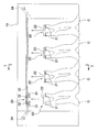
- the cloth spreading apparatus A is an apparatus for suspending the cloth C, forming it into a rectangular shape that is neatly stretched into a quadrangle, and putting it into a roll ironer or the like as a processing apparatus for the next process.
- the cloth C handled by this apparatus is after washing and drying, before ironing, and has a square shape. This square includes both square and rectangular shapes. Examples of such cloth C include sheets, futon wrapping, and towels.
- reference numeral 10 denotes an apparatus main body, and a loading unit 20 is provided on the front surface thereof.
- the input unit 20 includes a pair of input chucks 21 and 21 that grip both corners of one side of the cloth C, a chuck base 22 to which the input chucks 21 and 21 are fixed, and an elevating device 23 that moves the chuck base 22 up and down. And.
- the pair of input chucks 21 and 21 can be moved up and down by the lifting device 23.
- the chuck base 22 has a width about the width of a person's shoulder, and input chucks 21 and 21 are provided at both left and right ends thereof.
- Each input chuck 21 is composed of two chucks arranged on the left and right sides with a predetermined interval.
- the lifting device 23 raises the cloth C together with the input chucks 21, 21, and the cloth C is put on the stretcher 30 described later. Deliver C.
- the cloth spreading device A is provided with one or a plurality of input units 20.
- four input units 20 are provided, and the cloth C can be input from any of the input units 20.
- the elevating device 23 is driven by an actuator capable of speed / position control.
- Actuators capable of speed / position control include servo actuators such as servo motors and servo cylinders, stepping motors, and the like.
- the lifting device 23 of the present embodiment includes a rod 23a that guides the chuck base 22 to move up and down, an endless belt 23b that is disposed along the rod 23a and fixed to the chuck base 22, and is wound around the endless belt 23b. And a servo motor 23c that drives the pulley to rotate forward and reverse.
- the stretch portion 30 includes a pair of stretch chucks 31 and 31 that grip both corners of one side of the cloth C, a pair of carriages 32 and 32 to which the stretch chuck 31 is fixed, and the carriages 32 and 32 are horizontally moved.
- the rail 33 which guides so that it may move, and the traversing apparatus 34 which can move each carriage 32 separately are provided.
- the traversing device 34 is composed of, for example, a combination of a servo motor and an endless belt.
- the traversing device 34 can traverse the pair of spreading chucks 31, 31 individually.
- the traversing device 34 is not limited to a servo motor, and may be configured to be driven by another actuator capable of speed / position control.
- the spreading chuck 31 When the cloth C is raised by the operation of the loading unit 20, the spreading chuck 31 receives the cloth C from the loading chuck 21 and grips the corners. At this time, each spreading chuck 31 passes between two chucks constituting each input chuck 21. Therefore, the cloth C can be delivered without the spread chuck 31 and the input chuck 21 interfering with each other. Thereafter, the cloth C can be spread and hung by traversing the pair of spreading chucks 31, 31 so as to open to the left and right.
- a delivery unit 40 is disposed below the extension unit 30.
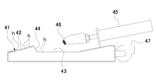
- the transfer unit 40 is a vacuum box 41 as an intermediate moving body that sucks and holds the upper edge of the cloth C when negative pressure is applied, an air cylinder or a servo motor as an advance / retreat device that moves the vacuum box 41 forward and backward (Not shown).
- the vacuum box 41 has a front part 42 inclined slightly forward on the upper surface and a step part 43 that is one step lower than the front part 42 behind the front part 42 and slightly between them. It has a rear surface 44 inclined upward (for example, about 30 degrees from the vertical), and further has an air cylinder 45 as a clamp driving device on the upper surface behind the stepped portion 43, and this air cylinder 45 has its piston rod. It is possible to support the clamp 46 made of an elastic body at the front end portion thereof and to move the clamp 46 forward and backward with respect to the rearward surface 44 by the forward and backward movement of the piston rod.
- the vacuum box 41 also has a negative pressure generator 47 such as a blower for generating a negative pressure in the vacuum box 41 at its rear end, and the negative pressure generated by the negative pressure generator 47 is applied to the front portion 42 on the upper surface.
- a negative pressure generator 47 such as a blower for generating a negative pressure in the vacuum box 41 at its rear end, and the negative pressure generated by the negative pressure generator 47 is applied to the front portion 42 on the upper surface.
- the large number of small holes h provided in the stepped portion 43 and the rearward facing surface 44 can affect the upper surface.
- a primary conveyor 50 including a belt conveyor is disposed below the delivery unit 40.
- the primary conveyor 50 includes a conveyor belt 51 having a large number of small holes, and a vacuum box 52 disposed below the conveying surface. While the cloth C is sucked by the primary conveyor 50, it can be fed backward.
- a secondary conveyor 60 composed of a belt conveyor is connected to the rear of the primary conveyor 50 so that the cloth C can be fed to a processing apparatus for the next process, for example, a roll ironer.
- An airflow shaping unit 11 is formed in the lower front portion of the apparatus body 10.
- the lower part of the airflow shaping unit 11 is connected to the blower 13 through the duct 12.
- a second duct 14 is formed on the back surface of the airflow shaping unit 11.
- the duct 14 is configured to communicate the vacuum box 52 of the primary conveyor 50 and the blower 13.
- An opening / closing plate 15 is provided between the ducts 12 and 14 and the blower 13. The opening / closing plate 15 selectively opens and closes the opening of the duct 12 and the opening of the duct 14. Therefore, the state can be selectively switched between a state in which air is sucked into the airflow shaping unit 11 from the front surface of the apparatus main body 10 and a state in which the vacuum box 52 of the primary conveyor 50 is operated.
- the cloth spreading device A includes a control device 70 that controls the operations of the lifting device 23 and the traversing device 34.
- the control device 70 is a computer configured with a CPU, a memory, and the like. By controlling the operation of the elevating device 23 and the traversing device 34 by the control device 70, the closing chuck 21 and the spreading chuck 31 can be operated in synchronization. Details thereof will be described later.
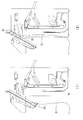
- the loading chuck 21 stands by at the lowered loading position. An operator searches for the corners on both sides of one side of the cloth C, and causes the input chucks 21 and 21 to grip each of them.
- the input chucks 21 and 21 are waiting at the input position a lowered.
- the stretch chucks 31 and 31 are in a standby state after the operation of the other fabric C is being performed or after the operation is completed.
- the spreading chuck 31 is waiting at the position where the cloth C is left and right (the position shown in FIG. 8A) or at a predetermined standby position. The operator finds both corners of one side of the cloth C, and causes the input chucks 21 and 21 to grip each of the corners.
- control device 70 operates the lifting device 23 and the traversing device 34 simultaneously to raise the charging chuck 21 from the loading position a to the delivery position d.
- the spreading chuck 31 is traversed to the delivery position d.
- the input chuck 21 and the extension chuck 31 operate simultaneously.
- “simultaneous operation” means that the other is operating within the period in which one is operating, and the timing of starting and stopping the operation may not be the same.
- the cloth spreading device A is provided with four throwing parts 20, and the cloth C can be thrown from any of the throwing parts 20.
- the input chuck 21 includes two chucks arranged on the left and right sides with a predetermined interval, and the extension chuck 31 passes between the two chucks so that the extension chuck 31 and the input chuck are provided.
- Cloth 21 can be delivered without interfering with 21. Therefore, when the fabric C is delivered, the loading chuck 21 is operated so as to pass the delivery position d while being stopped at the delivery position d. Therefore, it is necessary that the spreading chuck 31 arrives at the delivery position d before the closing chuck 21. In such a case, the speed of the input chuck 21 and the extension chuck 31 may be adjusted so that the extension chuck 31 arrives at the transfer position d first, or temporarily before the input chuck 21 at the transfer position d. You may make it stop.
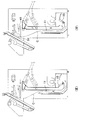
- control device 70 operates the lifting device 23 and the traversing device 34 simultaneously to raise the closing chucks 21, 21 from the delivery position d to the high position c, 31 is traversed left and right from the delivery position d.
- the cloth C is unfolded by spreading the pair of spreading chucks 31, 31 left and right.
- the making chuck 21 is lowered from the high position c to the making position a.
- the input chuck 21 and the extension chuck 31 operate simultaneously. Even in this case, it is only necessary that the other is operating within a period during which one is operating, and the timing of starting and stopping the operation may not be the same.
- the spread chuck 31 starts traversing after rising to a position where the input chuck 21 does not interfere. In general, since the traverse distance of the spreading chuck 31 is longer than the ascending distance of the feeding chuck 21, the spreading chuck 31 is traversed even after the feeding chuck 21 reaches the high position c and stops.
- the washed cloth can be spread and the cloth can be carried out to a roll irona or the like, and the vacuum box 41 delivers a particularly heavy cloth.
- the received fabric can be sufficiently held and reliably delivered to the primary conveyor 50 at a predetermined position.
- the clamp driving device is the air cylinder 45 that linearly moves the clamp 46 forward and backward with respect to the rearward surface 44. Therefore, the vacuum of the clamp 46 and the air cylinder 45 is reduced. Since the protrusion height from the upper surface of the box 41 can be reduced, the configuration of the fabric spreading device A can be made compact in the height direction.
- the vacuum box 41 is formed on the upper surface of the cloth C on the upper surface with negative pressure acting on the upper surface from the inside by the negative pressure generator 47 in addition to the rearward surface 44 and the clamp 46. Since the upper end portion is held, the received cloth can be more firmly held and delivered to the primary conveyor 50 more reliably at a predetermined position.
- the present invention has been described based on the illustrated examples, the present invention is not limited to the above-described examples, and can be appropriately changed within the scope of the claims. Instead of linearly moving back and forth with respect to the surface, it may be moved back and forth by swinging. Further, the rearward surface 44 can be set at an appropriate inclination angle and may be vertical.
- the received fabric is sufficiently retained, especially when delivering heavy fabrics or increasing the operating speed especially to increase the supply efficiency to the ironing roller.
- the received fabric can be reliably delivered to the belt conveyor at a predetermined position.
- a Cloth extension device C Cloth 10 Device body 20 Input portion 21 Input chuck 22 Chuck base 23 Lifting device 23a Rod 23b Endless belt 23c Servo motor 30 Extension portion 31 Extension chuck 32 Carriage 33 Rail 34 Traverse device 40 Delivery portion 41 Vacuum box 42 Front 43 Step 44 Backward 45 Air Cylinder 46 Clamp 47 Negative Pressure Generator 50 Primary Conveyor 60 Secondary Conveyor 70 Control Device
Landscapes
- Engineering & Computer Science (AREA)
- Textile Engineering (AREA)
- Treatment Of Fiber Materials (AREA)
Abstract
L'invention porte sur un dispositif d'étirement de tissu dans lequel : une paire de mandrins d'insertion sont fixés, dans une position abaissée, aux coins adjacents d'un tissu, pour soulever le tissu jusqu'à une position transversale des mandrins d'étirement ; une paire de mandrins d'étirement se déplacent transversalement en s'approchant l'une de l'autre, reçoivent les coins adjacents du tissu à partir des mandrins d'insertion, puis se déplacent transversalement en s'éloignant l'une de l'autre pour tirer les coins adjacents de telle sorte que le tissu soit étiré ; un corps mobile intermédiaire reçoit et maintient, dans une position avant, une extrémité supérieure du tissu étiré à partir des mandrins d'étirement, puis libère l'extrémité supérieure tout en se déplaçant vers l'arrière de sorte que le tissu soit transféré sur une bande transporteuse ; et la bande transporteuse transporte le tissu, dans un état étiré, vers l'extérieur. Le corps mobile intermédiaire comprend : une surface tournée vers l'arrière qui se déplace vers le bas entre une section avant d'une surface supérieure et une section étagée plus basse que la section avant ; une pince qui fait face à la surface tournée vers l'arrière ; et un dispositif d'entraînement de pince qui déplace la pince vers l'avant et vers l'arrière de la surface tournée vers l'arrière de sorte que la partie supérieure du tissu soit maintenue et libérée entre la pince et la surface tournée vers l'arrière.
Priority Applications (5)
| Application Number | Priority Date | Filing Date | Title |
|---|---|---|---|
| US16/466,705 US10975517B2 (en) | 2016-12-09 | 2017-11-20 | Cloth spreading apparatus |
| DK17878277.7T DK3553215T3 (da) | 2016-12-09 | 2017-11-20 | Stofstrækningsindretning |
| CN201780072890.9A CN110023552B (zh) | 2016-12-09 | 2017-11-20 | 布料展平装置 |
| KR1020197016367A KR20190075132A (ko) | 2016-12-09 | 2017-11-20 | 직물류 전장 장치 |
| EP17878277.7A EP3553215B1 (fr) | 2016-12-09 | 2017-11-20 | Dispositif d'étirement de tissu |
Applications Claiming Priority (2)
| Application Number | Priority Date | Filing Date | Title |
|---|---|---|---|
| JP2016-239768 | 2016-12-09 | ||
| JP2016239768A JP6621731B2 (ja) | 2016-12-09 | 2016-12-09 | 布類展張装置 |
Publications (1)
| Publication Number | Publication Date |
|---|---|
| WO2018105363A1 true WO2018105363A1 (fr) | 2018-06-14 |
Family
ID=62492039
Family Applications (1)
| Application Number | Title | Priority Date | Filing Date |
|---|---|---|---|
| PCT/JP2017/041613 Ceased WO2018105363A1 (fr) | 2016-12-09 | 2017-11-20 | Dispositif d'étirement de tissu |
Country Status (7)
| Country | Link |
|---|---|
| US (1) | US10975517B2 (fr) |
| EP (1) | EP3553215B1 (fr) |
| JP (1) | JP6621731B2 (fr) |
| KR (1) | KR20190075132A (fr) |
| CN (1) | CN110023552B (fr) |
| DK (1) | DK3553215T3 (fr) |
| WO (1) | WO2018105363A1 (fr) |
Cited By (4)
| Publication number | Priority date | Publication date | Assignee | Title |
|---|---|---|---|---|
| EP4089228A1 (fr) * | 2021-05-12 | 2022-11-16 | Herbert Kannegiesser GmbH | Procédé por guider du linge vers une calandre ou similaire |
| US20230013252A1 (en) * | 2019-12-20 | 2023-01-19 | Girbau Robotics | Machine for automatically feeding flatwork articles |
| CN115667619A (zh) * | 2020-05-25 | 2023-01-31 | 简森丹麦有限公司 | 亚麻布铺展机装置 |
| US12163274B2 (en) | 2020-05-25 | 2024-12-10 | Jensen Denmark A/S | Linen spreader apparatus |
Families Citing this family (5)
| Publication number | Priority date | Publication date | Assignee | Title |
|---|---|---|---|---|
| JP7064841B2 (ja) * | 2017-09-27 | 2022-05-11 | 株式会社プレックス | 布類展開装置 |
| DE102019135659A1 (de) * | 2019-11-28 | 2021-06-02 | Herbert Kannegiesser Gmbh | Verfahren und Vorrichtung zum Ergreifen rechteckiger textiler Gegenstände und/oder zum Zuführen rechtecktiger textiler Gegenstände zu einer Behandlungseinrichtung |
| JP7784153B2 (ja) * | 2021-02-26 | 2025-12-11 | 東都フォルダー工業株式会社 | 布類投入装置と、その布類投入装置を有する布類展開装置 |
| WO2022208796A1 (fr) * | 2021-03-31 | 2022-10-06 | 東都フォルダー工業株式会社 | Dispositif d'alimentation en tissu et dispositif d'étalement de tissu qui comprend ledit dispositif d'alimentation en tissu |
| CN114314155B (zh) * | 2022-01-12 | 2023-05-05 | 江苏川岛洗涤机械科技有限公司 | 一种展布机穿梭板的运行控制方法 |
Citations (3)
| Publication number | Priority date | Publication date | Assignee | Title |
|---|---|---|---|---|
| JP2002113295A (ja) * | 2000-10-12 | 2002-04-16 | Tookai:Kk | ランドリー装置におけるシーツ等方形状布類の移載装置 |
| JP2012082038A (ja) * | 2010-10-08 | 2012-04-26 | Yozo Maejima | 布類反転装置 |
| WO2016017090A1 (fr) * | 2014-07-31 | 2016-02-04 | 株式会社プレックス | Dispositif d'étalement de tissu |
Family Cites Families (11)
| Publication number | Priority date | Publication date | Assignee | Title |
|---|---|---|---|---|
| DE1785548B1 (de) * | 1968-05-18 | 1971-01-21 | Kannegiesser Maschinen | Zufuehrvorrichtung zum Zufuehren von Waeschestuecken zu einer Mangel |
| US3568341A (en) * | 1970-01-29 | 1971-03-09 | Ametek Inc | Feeder with diverging slots |
| US3729846A (en) * | 1970-05-01 | 1973-05-01 | Mc Graw Edison Co | Laundry feeding machine |
| DE3119600C2 (de) * | 1981-05-16 | 1985-02-14 | Herbert Kannegiesser Gmbh + Co, 4973 Vlotho | Vorrichtung zum Zuführen von Wäschestücken zu einer Mangel |
| CH696668A5 (de) * | 1996-03-08 | 2007-09-14 | Jensen Ag Burgdorf | Verfahren zum Zuführen von Wäschestücken zu einem Bearbeitungsgerät sowie Zuführvorrichtung. |
| JP4204154B2 (ja) * | 1999-11-26 | 2009-01-07 | 株式会社プレックス | 布類展張方法及び布類展張機 |
| ATE456698T1 (de) * | 2003-10-10 | 2010-02-15 | Jean Michel Soc | Vorrichtung und verfahren zum einführen von flachen kleidungsstücken in ein wäschebehandlungsaggregat |
| JP4358820B2 (ja) * | 2005-12-15 | 2009-11-04 | 洋左右 前嶋 | 布類投入装置 |
| DK176866B1 (da) * | 2006-05-19 | 2010-02-01 | Jensen Denmark As | Apparat til ilægning af tøjstykker |
| JP2013215361A (ja) * | 2012-04-06 | 2013-10-24 | Plex International Design Co Ltd | 布類展開装置 |
| EP2977505B1 (fr) * | 2014-07-24 | 2021-02-17 | Girbau Robotics | Machine d'épandage avec un dispositif auxiliaire de dépôt et d'alimentation d'articles vestimentaires plats sur une bande transporteuse |
-
2016
- 2016-12-09 JP JP2016239768A patent/JP6621731B2/ja active Active
-
2017
- 2017-11-20 DK DK17878277.7T patent/DK3553215T3/da active
- 2017-11-20 KR KR1020197016367A patent/KR20190075132A/ko not_active Abandoned
- 2017-11-20 EP EP17878277.7A patent/EP3553215B1/fr active Active
- 2017-11-20 CN CN201780072890.9A patent/CN110023552B/zh active Active
- 2017-11-20 WO PCT/JP2017/041613 patent/WO2018105363A1/fr not_active Ceased
- 2017-11-20 US US16/466,705 patent/US10975517B2/en active Active
Patent Citations (4)
| Publication number | Priority date | Publication date | Assignee | Title |
|---|---|---|---|---|
| JP2002113295A (ja) * | 2000-10-12 | 2002-04-16 | Tookai:Kk | ランドリー装置におけるシーツ等方形状布類の移載装置 |
| JP2012082038A (ja) * | 2010-10-08 | 2012-04-26 | Yozo Maejima | 布類反転装置 |
| WO2016017090A1 (fr) * | 2014-07-31 | 2016-02-04 | 株式会社プレックス | Dispositif d'étalement de tissu |
| JP2016033271A (ja) | 2014-07-31 | 2016-03-10 | 株式会社プレックス | 布類展開装置 |
Non-Patent Citations (1)
| Title |
|---|
| See also references of EP3553215A4 |
Cited By (6)
| Publication number | Priority date | Publication date | Assignee | Title |
|---|---|---|---|---|
| US20230013252A1 (en) * | 2019-12-20 | 2023-01-19 | Girbau Robotics | Machine for automatically feeding flatwork articles |
| US12234600B2 (en) * | 2019-12-20 | 2025-02-25 | Girbau Robotics | Machine for automatically feeding flatwork articles |
| CN115667619A (zh) * | 2020-05-25 | 2023-01-31 | 简森丹麦有限公司 | 亚麻布铺展机装置 |
| US12018428B2 (en) | 2020-05-25 | 2024-06-25 | Jensen Denmark A/S | Linen spreader apparatus |
| US12163274B2 (en) | 2020-05-25 | 2024-12-10 | Jensen Denmark A/S | Linen spreader apparatus |
| EP4089228A1 (fr) * | 2021-05-12 | 2022-11-16 | Herbert Kannegiesser GmbH | Procédé por guider du linge vers une calandre ou similaire |
Also Published As
| Publication number | Publication date |
|---|---|
| CN110023552B (zh) | 2021-06-08 |
| EP3553215A4 (fr) | 2019-12-25 |
| CN110023552A (zh) | 2019-07-16 |
| EP3553215B1 (fr) | 2022-01-05 |
| KR20190075132A (ko) | 2019-06-28 |
| US20190301081A1 (en) | 2019-10-03 |
| JP2018095979A (ja) | 2018-06-21 |
| JP6621731B2 (ja) | 2019-12-18 |
| DK3553215T3 (da) | 2022-03-28 |
| EP3553215A1 (fr) | 2019-10-16 |
| US10975517B2 (en) | 2021-04-13 |
Similar Documents
| Publication | Publication Date | Title |
|---|---|---|
| JP6621731B2 (ja) | 布類展張装置 | |
| JP6389686B2 (ja) | 布類展開装置 | |
| JP6929138B2 (ja) | 布類展張装置 | |
| JP6940420B2 (ja) | 布類展張装置 | |
| JP3781376B1 (ja) | 布類展張搬送方法および装置 | |
| WO2016047024A1 (fr) | Appareil d'étalement de tissu carré | |
| JP2007092255A (ja) | 布類展張方法および布類展張機 | |
| JP5111224B2 (ja) | 布類展張搬送機 | |
| JP6929417B1 (ja) | 布類展張装置 | |
| CN110249090B (zh) | 布料展平装置 | |
| JP4808065B2 (ja) | 布類展張搬送機 | |
| HK40005799A (en) | Cloth spreading apparatus | |
| JP2016059733A (ja) | 方形状布類展開装置 | |
| JP2016106892A (ja) | 方形状布類展開装置 | |
| JP2008121142A (ja) | 布類展張搬送機 | |
| JPH05293299A (ja) | 方形状布類の展開装置 | |
| JP7018326B2 (ja) | 布類展開装置 | |
| TW202020256A (zh) | 布類撐開裝置 | |
| JPH0728996B2 (ja) | 方形状布類の縁出し装置 | |
| HK40009113A (en) | Cloth spreading apparatus |
Legal Events
| Date | Code | Title | Description |
|---|---|---|---|
| 121 | Ep: the epo has been informed by wipo that ep was designated in this application |
Ref document number: 17878277 Country of ref document: EP Kind code of ref document: A1 |
|
| ENP | Entry into the national phase |
Ref document number: 20197016367 Country of ref document: KR Kind code of ref document: A |
|
| NENP | Non-entry into the national phase |
Ref country code: DE |
|
| ENP | Entry into the national phase |
Ref document number: 2017878277 Country of ref document: EP Effective date: 20190709 |