WO2018105501A1 - 副室式ガスエンジン - Google Patents
副室式ガスエンジン Download PDFInfo
- Publication number
- WO2018105501A1 WO2018105501A1 PCT/JP2017/043202 JP2017043202W WO2018105501A1 WO 2018105501 A1 WO2018105501 A1 WO 2018105501A1 JP 2017043202 W JP2017043202 W JP 2017043202W WO 2018105501 A1 WO2018105501 A1 WO 2018105501A1
- Authority
- WO
- WIPO (PCT)
- Prior art keywords
- chamber
- sub
- injection hole
- ignition
- central axis
- Prior art date
- Legal status (The legal status is an assumption and is not a legal conclusion. Google has not performed a legal analysis and makes no representation as to the accuracy of the status listed.)
- Ceased
Links
Images



Classifications
-
- F—MECHANICAL ENGINEERING; LIGHTING; HEATING; WEAPONS; BLASTING
- F02—COMBUSTION ENGINES; HOT-GAS OR COMBUSTION-PRODUCT ENGINE PLANTS
- F02B—INTERNAL-COMBUSTION PISTON ENGINES; COMBUSTION ENGINES IN GENERAL
- F02B19/00—Engines characterised by precombustion chambers
- F02B19/16—Chamber shapes or constructions not specific to sub-groups F02B19/02 - F02B19/10
- F02B19/18—Transfer passages between chamber and cylinder
-
- F—MECHANICAL ENGINEERING; LIGHTING; HEATING; WEAPONS; BLASTING
- F02—COMBUSTION ENGINES; HOT-GAS OR COMBUSTION-PRODUCT ENGINE PLANTS
- F02B—INTERNAL-COMBUSTION PISTON ENGINES; COMBUSTION ENGINES IN GENERAL
- F02B19/00—Engines characterised by precombustion chambers
- F02B19/10—Engines characterised by precombustion chambers with fuel introduced partly into pre-combustion chamber, and partly into cylinder
-
- F—MECHANICAL ENGINEERING; LIGHTING; HEATING; WEAPONS; BLASTING
- F02—COMBUSTION ENGINES; HOT-GAS OR COMBUSTION-PRODUCT ENGINE PLANTS
- F02B—INTERNAL-COMBUSTION PISTON ENGINES; COMBUSTION ENGINES IN GENERAL
- F02B19/00—Engines characterised by precombustion chambers
- F02B19/10—Engines characterised by precombustion chambers with fuel introduced partly into pre-combustion chamber, and partly into cylinder
- F02B19/1004—Engines characterised by precombustion chambers with fuel introduced partly into pre-combustion chamber, and partly into cylinder details of combustion chamber, e.g. mounting arrangements
-
- F—MECHANICAL ENGINEERING; LIGHTING; HEATING; WEAPONS; BLASTING
- F02—COMBUSTION ENGINES; HOT-GAS OR COMBUSTION-PRODUCT ENGINE PLANTS
- F02B—INTERNAL-COMBUSTION PISTON ENGINES; COMBUSTION ENGINES IN GENERAL
- F02B19/00—Engines characterised by precombustion chambers
- F02B19/10—Engines characterised by precombustion chambers with fuel introduced partly into pre-combustion chamber, and partly into cylinder
- F02B19/1004—Engines characterised by precombustion chambers with fuel introduced partly into pre-combustion chamber, and partly into cylinder details of combustion chamber, e.g. mounting arrangements
- F02B19/1014—Engines characterised by precombustion chambers with fuel introduced partly into pre-combustion chamber, and partly into cylinder details of combustion chamber, e.g. mounting arrangements design parameters, e.g. volume, torch passage cross sectional area, length, orientation, or the like
-
- F—MECHANICAL ENGINEERING; LIGHTING; HEATING; WEAPONS; BLASTING
- F02—COMBUSTION ENGINES; HOT-GAS OR COMBUSTION-PRODUCT ENGINE PLANTS
- F02B—INTERNAL-COMBUSTION PISTON ENGINES; COMBUSTION ENGINES IN GENERAL
- F02B19/00—Engines characterised by precombustion chambers
- F02B19/10—Engines characterised by precombustion chambers with fuel introduced partly into pre-combustion chamber, and partly into cylinder
- F02B19/1019—Engines characterised by precombustion chambers with fuel introduced partly into pre-combustion chamber, and partly into cylinder with only one pre-combustion chamber
-
- F—MECHANICAL ENGINEERING; LIGHTING; HEATING; WEAPONS; BLASTING
- F02—COMBUSTION ENGINES; HOT-GAS OR COMBUSTION-PRODUCT ENGINE PLANTS
- F02B—INTERNAL-COMBUSTION PISTON ENGINES; COMBUSTION ENGINES IN GENERAL
- F02B19/00—Engines characterised by precombustion chambers
- F02B19/10—Engines characterised by precombustion chambers with fuel introduced partly into pre-combustion chamber, and partly into cylinder
- F02B19/1019—Engines characterised by precombustion chambers with fuel introduced partly into pre-combustion chamber, and partly into cylinder with only one pre-combustion chamber
- F02B19/108—Engines characterised by precombustion chambers with fuel introduced partly into pre-combustion chamber, and partly into cylinder with only one pre-combustion chamber with fuel injection at least into pre-combustion chamber, i.e. injector mounted directly in the pre-combustion chamber
-
- F—MECHANICAL ENGINEERING; LIGHTING; HEATING; WEAPONS; BLASTING
- F02—COMBUSTION ENGINES; HOT-GAS OR COMBUSTION-PRODUCT ENGINE PLANTS
- F02B—INTERNAL-COMBUSTION PISTON ENGINES; COMBUSTION ENGINES IN GENERAL
- F02B19/00—Engines characterised by precombustion chambers
- F02B19/12—Engines characterised by precombustion chambers with positive ignition
-
- F—MECHANICAL ENGINEERING; LIGHTING; HEATING; WEAPONS; BLASTING
- F02—COMBUSTION ENGINES; HOT-GAS OR COMBUSTION-PRODUCT ENGINE PLANTS
- F02B—INTERNAL-COMBUSTION PISTON ENGINES; COMBUSTION ENGINES IN GENERAL
- F02B19/00—Engines characterised by precombustion chambers
- F02B19/16—Chamber shapes or constructions not specific to sub-groups F02B19/02 - F02B19/10
-
- F—MECHANICAL ENGINEERING; LIGHTING; HEATING; WEAPONS; BLASTING
- F02—COMBUSTION ENGINES; HOT-GAS OR COMBUSTION-PRODUCT ENGINE PLANTS
- F02M—SUPPLYING COMBUSTION ENGINES IN GENERAL WITH COMBUSTIBLE MIXTURES OR CONSTITUENTS THEREOF
- F02M21/00—Apparatus for supplying engines with non-liquid fuels, e.g. gaseous fuels stored in liquid form
- F02M21/02—Apparatus for supplying engines with non-liquid fuels, e.g. gaseous fuels stored in liquid form for gaseous fuels
-
- F—MECHANICAL ENGINEERING; LIGHTING; HEATING; WEAPONS; BLASTING
- F02—COMBUSTION ENGINES; HOT-GAS OR COMBUSTION-PRODUCT ENGINE PLANTS
- F02M—SUPPLYING COMBUSTION ENGINES IN GENERAL WITH COMBUSTIBLE MIXTURES OR CONSTITUENTS THEREOF
- F02M21/00—Apparatus for supplying engines with non-liquid fuels, e.g. gaseous fuels stored in liquid form
- F02M21/02—Apparatus for supplying engines with non-liquid fuels, e.g. gaseous fuels stored in liquid form for gaseous fuels
- F02M21/0218—Details on the gaseous fuel supply system, e.g. tanks, valves, pipes, pumps, rails, injectors or mixers
-
- F—MECHANICAL ENGINEERING; LIGHTING; HEATING; WEAPONS; BLASTING
- F02—COMBUSTION ENGINES; HOT-GAS OR COMBUSTION-PRODUCT ENGINE PLANTS
- F02M—SUPPLYING COMBUSTION ENGINES IN GENERAL WITH COMBUSTIBLE MIXTURES OR CONSTITUENTS THEREOF
- F02M21/00—Apparatus for supplying engines with non-liquid fuels, e.g. gaseous fuels stored in liquid form
- F02M21/02—Apparatus for supplying engines with non-liquid fuels, e.g. gaseous fuels stored in liquid form for gaseous fuels
- F02M21/0218—Details on the gaseous fuel supply system, e.g. tanks, valves, pipes, pumps, rails, injectors or mixers
- F02M21/0248—Injectors
-
- F—MECHANICAL ENGINEERING; LIGHTING; HEATING; WEAPONS; BLASTING
- F02—COMBUSTION ENGINES; HOT-GAS OR COMBUSTION-PRODUCT ENGINE PLANTS
- F02M—SUPPLYING COMBUSTION ENGINES IN GENERAL WITH COMBUSTIBLE MIXTURES OR CONSTITUENTS THEREOF
- F02M21/00—Apparatus for supplying engines with non-liquid fuels, e.g. gaseous fuels stored in liquid form
- F02M21/02—Apparatus for supplying engines with non-liquid fuels, e.g. gaseous fuels stored in liquid form for gaseous fuels
- F02M21/0218—Details on the gaseous fuel supply system, e.g. tanks, valves, pipes, pumps, rails, injectors or mixers
- F02M21/0248—Injectors
- F02M21/0281—Adapters, sockets or the like to mount injection valves onto engines; Fuel guiding passages between injectors and the air intake system or the combustion chamber
-
- Y—GENERAL TAGGING OF NEW TECHNOLOGICAL DEVELOPMENTS; GENERAL TAGGING OF CROSS-SECTIONAL TECHNOLOGIES SPANNING OVER SEVERAL SECTIONS OF THE IPC; TECHNICAL SUBJECTS COVERED BY FORMER USPC CROSS-REFERENCE ART COLLECTIONS [XRACs] AND DIGESTS
- Y02—TECHNOLOGIES OR APPLICATIONS FOR MITIGATION OR ADAPTATION AGAINST CLIMATE CHANGE
- Y02T—CLIMATE CHANGE MITIGATION TECHNOLOGIES RELATED TO TRANSPORTATION
- Y02T10/00—Road transport of goods or passengers
- Y02T10/10—Internal combustion engine [ICE] based vehicles
- Y02T10/12—Improving ICE efficiencies
-
- Y—GENERAL TAGGING OF NEW TECHNOLOGICAL DEVELOPMENTS; GENERAL TAGGING OF CROSS-SECTIONAL TECHNOLOGIES SPANNING OVER SEVERAL SECTIONS OF THE IPC; TECHNICAL SUBJECTS COVERED BY FORMER USPC CROSS-REFERENCE ART COLLECTIONS [XRACs] AND DIGESTS
- Y02—TECHNOLOGIES OR APPLICATIONS FOR MITIGATION OR ADAPTATION AGAINST CLIMATE CHANGE
- Y02T—CLIMATE CHANGE MITIGATION TECHNOLOGIES RELATED TO TRANSPORTATION
- Y02T10/00—Road transport of goods or passengers
- Y02T10/10—Internal combustion engine [ICE] based vehicles
- Y02T10/30—Use of alternative fuels, e.g. biofuels
Definitions
- the present disclosure is a sub-chamber type in which the mixture in the main combustion chamber is burned by ejecting the combustion flame generated in the sub-combustion chamber (sub-chamber) into the main combustion chamber (main chamber) through the plurality of injection holes. It relates to a gas engine.
- sub-chamber gas engines have been known as engines capable of efficiently burning lean premixed air-fuel (for example, Patent Documents 1 and 2).
- the sub-chamber gas engine has a main combustion chamber (main chamber) defined between the piston and the cylinder head, and a sub chamber provided close to the main combustion chamber such as the cylinder upper portion, The main combustion chamber and the sub-chamber communicate with each other through the plurality of injection holes. Then, by igniting the air-fuel mixture in the auxiliary chamber with an ignition device such as an ignition plug, the combustion flame generated by the ignition is ejected from each of the plurality of injection holes provided at the lower portion of the auxiliary chamber. Burn a lean premixed mixture.
- a portion of the lean premixed air introduced into the cylinder in the intake stroke of the engine flows into the sub-chamber through each of the plurality of injection holes in the compression step and is supplied to the sub-chamber
- the fuel is mixed with the fuel in the sub-chamber to generate a mixture having a concentration suitable for ignition in the sub-chamber.
- the air-fuel mixture in this state is ignited by the igniter, and the combustion flame is ejected from the sub-chamber injection hole to the cylinder, and the lean premixed air-fuel mixture in the main combustion chamber is ignited and burned as a torch (torch).
- the lean fuel can be burned in the main combustion chamber, achieving low fuel consumption.
- the combustion of the lean mixed gas in the main combustion chamber is a relatively low temperature combustion, the amount of generation of NOx and the like is reduced, and low pollution can be realized.
- Patent Document 1 discloses that the throat of the sub chamber (small diameter cylinder chamber described later) based on the knowledge that the shape of the injection hole affects the stability of the flow of the air-fuel mixture when the sub chamber is introduced. And the shape of a round chamfer along the periphery of the opening end on the throat side of the injection hole, in order to suppress combustion fluctuation.
- the air-fuel mixture in the main combustion chamber is ignited by the combustion flame (torch jet) ejected from the sub-chamber to the main combustion chamber through each of the plurality of injection holes in the combustion stroke.
- Variations in the flame propagation of the combustion flame of the mixture in the chamber contribute to abnormal combustion such as knocking.
- the cause of the variation in flame propagation speed in the main combustion chamber is that the temperature of the cylinder wall surface in the air supply side region on the side where the air supply port exists is an exhaust port.
- the sum of the injection hole areas of the air supply side injection holes disposed in the air supply side area is the exhaust side area. It is disclosed to make it larger than the sum of the injection hole area of the disposed exhaust side injection holes. As a result, the time taken for the flame of the air-fuel mixture on the air supply side ignited by the torch jet from the air supply side injection hole to reach the cylinder wall surface is shortened, thereby suppressing the occurrence of knocking.
- the ignition device (ignition unit) of the auxiliary chamber may be difficult to arrange on the central axis of the cylinder due to the structural reasons of the auxiliary chamber, etc., and is arranged at a position deviated from the central axis of the cylinder There are cases (see FIG. 1 described later). In such a case, in the sub-chamber, flame propagation of the combustion flame on the side where the ignition device is disposed is relatively faster than flame propagation on the side where the ignition device on the opposite side is not disposed. The inventors of the present invention have found out.
- a plurality of injection holes in the sub chamber are formed at equal intervals in plan view, and a large amount of unburned gas flows out from the sub chamber to the main combustion chamber through the injection holes which the combustion flame reached relatively late. It will be easier.
- the ejection start timing and the ejection strength of the torch jets vary among the plurality of injection holes, and, along with this, the lean pre-ignition of the main combustion chamber is respectively ignited by the torch jets from each of the plurality of injection holes. Variations also occur in the ignition timing of the mixture and flame propagation (such as flame propagation velocity) of the combustion flame. Variation in flame propagation in the main combustion chamber leaves unburned gas in a region where flame propagation of the combustion flame is delayed, which causes knocking and is one factor that hinders improvement in thermal efficiency and output of the gas engine.
- At least one embodiment of the present invention aims to provide a sub-chamber type gas engine capable of suppressing variation in flame propagation in the main combustion chamber.
- a sub-chamber gas engine according to at least one embodiment of the present invention, A main chamber forming part forming a main combustion chamber, An auxiliary chamber forming portion forming an auxiliary chamber communicated with the main combustion chamber through a plurality of injection holes; An ignition device provided at an upper portion inside the sub chamber, wherein the ignition portion of the ignition device is located at a predetermined distance from a central axis of a main chamber of the main combustion chamber;
- the sub-chamber is defined as a boundary perpendicular to a straight line passing through the sub-chamber central axis of the sub-chamber and the ignition portion, as a boundary passing through the sub-chamber central axis.
- the distance between the auxiliary chamber side opening end portion connected to the auxiliary chamber and the auxiliary chamber central axis in the remote side specific injection hole which is at least one injection hole in the ignition remote side region is the ignition proximity side
- the distance between the auxiliary chamber side opening end portion connected to the auxiliary chamber and the auxiliary chamber central axis in the adjacent specific injection hole which is at least one injection hole in the ignition proximal region is the ignition distance
- the distance between the sub-chamber side open end of the far side specific injection hole, which is the at least one injection hole in the side area, and the sub chamber center axis is shorter than any one of them.
- the distance between the far side specific injection hole in the region relatively distant to the ignition part (ignition far side region) and the subchamber center axis line is in the region relatively close to the ignition part ( It is shorter than the distance between the near side specific injection hole disposed in the near ignition region) and the central axis of the sub chamber.
- the distance between the near side specific injection hole and the distance between the auxiliary chamber central axis is shorter than the distance between the distant specific injection hole and the auxiliary chamber central axis.
- the inventors of the present invention have found that the combustion flame generated by the ignition by the ignition device is a passing portion of the sub chamber side opening end of the near side specific injection hole, a passing portion of the sub chamber central axis (bottom center of the sub chamber) It has been found that the secondary chamber side opening end of the side specific injection hole is reached in order. Furthermore, the present inventors form the secondary chamber side open end of the remote side specific injection hole on the bottom center side of the secondary chamber, so that the secondary chamber side open end of the remote side specific injection hole is ignited by the ignition device.
- the respective sub chamber side open ends of the near side specific injection hole and the far side specific injection hole Since it is possible to shorten the time difference of the arrival time of the combustion flame generated in the sub chamber by the ignition device by the ignition device, from the main chamber side open end of each of the near side specific injection hole and the far side specific injection hole.
- the injection start timing and the injection intensity of the combustion flames (torch jets) respectively ejected can be adjusted to be equal, and the variation of the flame propagation in the main combustion chamber can be suppressed. Further, by suppressing the variation in flame propagation in the main combustion chamber, it is possible to suppress the knocking that occurs due to the delayed arrival of the flame, and it is possible to improve the efficiency of the engine.
- the near side specific injection hole is a closest injection hole in which the main chamber side opening end connected to the main combustion chamber is the injection hole in the near ignition region closest to the ignition portion in plan view
- the far side specific injection hole is a farthest injection hole in which the main chamber side opening end is an injection hole in the far ignition region farthest from the ignition portion in plan view.
- the sub chamber side opening end of the injection hole (the farthest injection hole) and the center of the sub chamber with the main chamber side opening end farthest from the ignition portion The distance from the axis is shorter than the distance between the sub chamber side opening end of the injection hole (the closest injection hole) whose main chamber side opening end is closest to the ignition part and the sub chamber central axis.
- the timing at which the combustion flame produced by ignition by the ignition device reaches the farthest injection port can be adjusted more quickly, and in the sub chamber, the combustion flame produced by ignition by the ignition device reaches the closest at the earliest. It is possible to make the injection start timings of the injection holes and the farthest injection holes close to each other. Therefore, it is possible to efficiently suppress the dispersion of the flame propagation in the main combustion chamber by suppressing the dispersion of the ejection start timing when the flame is ejected from each of the plurality of injection holes to the main combustion chamber.
- the distance between the sub chamber side opening end of the far side specific injection hole and the sub chamber central axis is the distance between the sub chamber side opening end of each of the plurality of injection holes and the sub chamber central axis Shorter than average.
- the sub-chamber side opening end of the far side specific injection hole is made shorter by making the distance between the sub chamber side opening end of the far side specific injection hole and the sub chamber center axis shorter than average.
- the distance between the portion and the sub chamber central axis can be shorter than the distance between the sub chamber side opening end of the near side specific injection hole and the sub chamber central axis.
- the distance between the sub chamber side opening end of the near side specific injection hole and the sub chamber central axis is the distance between the sub chamber side opening end of each of the plurality of injection holes and the sub chamber central axis Cs Shorter than the average of
- the configuration of (4) by setting the distance between the sub chamber side opening end of the near side specific injection hole and the sub chamber center axis shorter than the average, the sub chamber side opening end of the near side specific injection hole The distance between the portion and the subchamber central axis can be shorter than the distance between the subchamber side opening end of the far side specific injection hole and the subchamber central axis.
- the depression angle of the far side specific injection hole is the same as the depression angle of the near side specific injection hole.
- the combustion flames (torch jets) ejected from the respective injection holes reach the cylinder wall surface respectively
- the timing at which combustion flames produced by ignition by the ignition device reach the sub chamber side opening end of each of the near side specific injection hole and the far side specific injection hole while suppressing the influence on the time required for flame propagation Time difference can be shortened.
- a sub-chamber gas engine according to at least one embodiment of the present invention, A main chamber forming part forming a main combustion chamber, An auxiliary chamber forming portion forming an auxiliary chamber communicated with the main combustion chamber through a plurality of injection holes; An ignition device provided at an upper portion inside the sub chamber, wherein the ignition portion of the ignition device is located at a predetermined distance from a central axis of a main chamber of the main combustion chamber;
- the sub-chamber is defined as a boundary perpendicular to a straight line passing through the sub-chamber central axis of the sub-chamber and the ignition portion, as a boundary passing through the sub-chamber central axis.
- the injection hole length of the far side specific injection hole which is the at least one injection hole in the ignition far side area is the injection hole length of the near side specific injection hole which is the at least one injection hole in the near ignition area. Less than.
- the injection hole length of the distant specific injection hole in the region relatively distant to the ignition part in the plan view of the sub chamber is the region closer to the ignition part It is shorter than the injection hole length of the near side specific injection hole disposed inside (the ignition near side region).
- the injection hole length is longer, it takes more time for the combustion flame generated by the ignition by the ignition device to pass through the injection hole.
- the nozzle length of the far side specific injection hole to which this combustion flame reaches later is made shorter than the nozzle hole length of the near side specific injection hole to which combustion flame reaches earlier.
- the near side specific injection hole includes a closest injection hole to be the injection hole in the ignition near region closest to the ignition portion in plan view
- the far side specific injection hole includes a farthest injection hole to be the injection hole in the far ignition region farthest from the ignition portion in plan view.
- the injection hole length of the injection hole (farthest injection hole) furthest from the ignition part in the planar view of the sub chamber is the injection hole (closest injection hole closest to the ignition part) It is shorter than the injection hole length of).
- the jet of the combustion flame (torch jet) jetted from each of the closest injection hole to which the combustion flame produced by the ignition by the ignition device reaches the earliest and the farthest injection hole to which the combustion flame reaches the slowest.
- the start timing and the ejection strength can be adjusted to be equal, and the variation in flame propagation of the torch jet in the main combustion chamber can be efficiently suppressed.
- the distance between the sub-chamber side open end of the far side specific injection hole and the central axis of the main chamber is equal to the distance between the sub-chamber side open end of the near side specific injection hole and the main chamber central axis
- the sub-chamber is formed with the sub-chamber central axis and the main chamber central axis being offset so as to be longer than the above distance.
- the sub-chamber is formed to be biased to the far side specific injection hole side so that the main chamber central axis and the sub chamber central axis are deviated in the sub-chamber forming portion.
- the thickness of the wall of the sub chamber formed by the chamber forming portion is thinner at the far side specific injection hole than at the near side specific injection hole. By this, it is possible to form the injection hole length of the far side specific injection hole shorter than the injection hole length of the near side specific injection hole.
- a sub-chamber gas engine according to at least one embodiment of the present invention, A main chamber forming part forming a main combustion chamber, An auxiliary chamber forming portion forming an auxiliary chamber communicated with the main combustion chamber through a plurality of injection holes; An ignition device provided at an upper portion inside the sub chamber, wherein the ignition portion of the ignition device is located at a predetermined distance from a central axis of a main chamber of the main combustion chamber;
- the sub-chamber is defined as a boundary perpendicular to a straight line passing through the sub-chamber central axis of the sub-chamber and the ignition portion, as a boundary passing through the main chamber central axis.
- the far side specific injection hole which is at least one of the injection holes in the far ignition region, includes a sub chamber side open end having a shape whose diameter decreases with distance from the connection position with the sub chamber.
- the sub-chamber side open end of the far side specific injection hole in the region relatively distant to the ignition part in the plan view of the sub-chamber (ignition far side region) is from the connection position with the sub-chamber It has a shape (bell-mouth shape) in which the diameter decreases with distance. That is, the auxiliary chamber side open end of the far side specific injection hole is formed by making the inlet pressure loss to the combustion flame generated by the ignition by the ignition device to be reduced. To reduce the deceleration of the combustion flame when flowing into the
- the far side specific injection hole is a farthest injection hole to be the injection hole in the ignition far area farthest from the ignition unit in plan view.
- the sub chamber side opening end portion of the injection hole (farthest injection hole) farthest from the ignition part has a bellmouth shape.
- the jet of the combustion flame (torch jet) jetted from each of the closest injection hole to which the combustion flame produced by the ignition by the ignition device reaches the earliest and the farthest injection hole to which the combustion flame reaches the slowest.
- the start timing and the ejection strength can be adjusted to be equal to each other, and the flame propagation variation in the main combustion chamber can be efficiently suppressed.
- the sub chamber is provided such that the main chamber central axis of the main combustion chamber and the sub chamber central axis of the sub chamber coincide with each other, and the ignition unit of the ignition device is the main combustion chamber In the sub-chamber type gas engine separated by a predetermined distance from the central axis of the main chamber (main chamber central axis), it is possible to suppress the variation in flame propagation in the main combustion chamber.
- the sub-chamber is A small diameter cylindrical chamber having a predetermined inner diameter, the small diameter cylinder forming portion forming a small diameter cylindrical chamber to which the plurality of injection holes are connected; A large diameter cylindrical chamber having an inner diameter larger than the small diameter cylindrical chamber, and a large diameter cylinder forming portion forming a large diameter cylindrical chamber in which the ignition portion of the ignition device is located;
- the main chamber central axis line coincides with the sub chamber central axis line of the small diameter cylindrical chamber.
- the sub-chamber is provided such that the main chamber central axis of the main combustion chamber and the sub-chamber central axis of the small diameter cylindrical chamber constituting the sub-chamber coincide with each other.
- the sub-chamber type gas engine in which the ignition unit is separated from the central axis (main chamber central axis) of the main combustion chamber by a predetermined distance, it is possible to suppress the variation in flame propagation in the main combustion chamber.
- the predetermined distance is greater than 10% of the maximum value of the inner diameter of the sub-chamber.
- a secondary chamber gas engine capable of suppressing variations in flame propagation in a main combustion chamber.
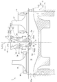
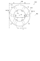
- FIG. 2 is a cross-sectional view schematically showing a sub-chamber type gas engine according to an embodiment of the present invention, wherein the distance between the sub-chamber central axis and the far side specific injection hole is shorter than that of the near side specific injection hole. It is a figure which shows roughly the cross section of the sub chamber formation part of FIG. 1, and is sectional drawing which cut
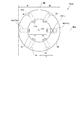
- FIG. 2 is a cross-sectional view schematically showing a sub-chamber type gas engine according to an embodiment of the present invention, wherein the distance between the sub-chamber central axis and the near side specific injection hole is shorter than that of the far side specific injection hole.
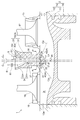
- FIG. 3 is a cross-sectional view schematically showing a sub-chamber type gas engine according to an embodiment of the present invention, in which the injection hole length of the far side specific injection hole is shorter than the injection hole length of the near side specific injection hole. It is a figure which shows roughly the cross section of the sub chamber formation part concerning one Embodiment of this invention, and is sectional drawing which cut
- FIG. 6 is a cross-sectional view schematically showing a sub-chamber type gas engine according to an embodiment of the present invention, which is a modification of the shape of the sub-chamber of FIG. 5. It is a figure which shows roughly the cross section of the sub chamber formation part concerning one Embodiment of this invention, and is sectional drawing which cut
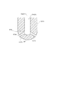
- FIG. 3 is a cross-sectional view schematically showing a sub-chamber type gas engine according to an embodiment of the present invention, wherein the sub-chamber side open end of the far side specific injection hole has a bellmouth shape.
- expressions that indicate that things such as “identical”, “equal” and “homogeneous” are equal states not only represent strictly equal states, but also have tolerances or differences with which the same function can be obtained. It also represents the existing state.
- expressions representing shapes such as quadrilateral shapes and cylindrical shapes not only represent shapes such as rectangular shapes and cylindrical shapes in a geometrically strict sense, but also uneven portions and chamfers within the range where the same effect can be obtained. The shape including a part etc. shall also be expressed.
- the expressions “comprising”, “having”, “having”, “including” or “having” one component are not exclusive expressions excluding the presence of other components.
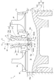
- FIG. 1 is a cross-sectional view schematically showing a sub-chamber type gas engine 1 according to an embodiment of the present invention, wherein the distance rf between the sub-chamber central axis Cs and the far side specific injection hole 43 is a near side specific injection hole Shorter than 42's.
- FIG. 2 is a view schematically showing a cross section of the sub chamber forming part 3 of FIG. 1, and is a cross sectional view of the sub chamber gas engine cut along line aa shown in FIG. FIG.
- FIG. 3 is a cross-sectional view schematically showing the sub-chamber type gas engine 1 according to one embodiment of the present invention, and the distance rn between the sub-chamber central axis Cs and the near side specific injection hole 42 is far side specific injection hole Shorter than 43's.
- FIG. 4 is a view schematically showing a cross section of the sub chamber forming portion 3 of FIG. 3, and is a cross sectional view of the sub chamber gas engine 1 cut along line aa shown in FIG.
- FIG. 5 is a cross-sectional view schematically showing the sub-chamber type gas engine 1 according to an embodiment of the present invention.
- the injection hole length Lf of the far side specific injection hole 43 is the injection hole length of the near side specific injection hole 42. It is shorter than Ln.
- FIG. 4 is a view schematically showing a cross section of the sub chamber forming portion 3 of FIG. 3, and is a cross sectional view of the sub chamber gas engine 1 cut along line aa shown in FIG.
- FIG. 5 is
- FIG. 6 is a view schematically showing a cross section of the sub chamber forming portion 3 according to the embodiment of the present invention, and is a cross sectional view of the sub chamber type gas engine 1 cut along line aa shown in FIG.
- FIG. 7 is a cross-sectional view schematically showing the sub-chamber type gas engine 1 according to an embodiment of the present invention, which is a modified example of the shape of the sub-chamber 3r of FIG.
- the sub-chamber type gas engine 1 includes a main chamber forming portion 2 forming the main combustion chamber 2r, a sub chamber forming portion 3 forming the sub chamber 3r, and a sub chamber 3r. And an ignition device 5 provided therein. More specifically, in the embodiment shown in FIGS. 1 to 9, as shown in FIGS. 1, 3, 5 and 7, the sub-chamber gas engine 1 has a cylindrical cylindrical structure inside.
- a cylinder 13 comprising a cylinder liner 11 and a cylinder head 12 having a recess structure capable of being covered at the top of the cylinder structure, a piston 14 housed in the cylinder 13 and reciprocating, and a cylinder head
- the main combustion chamber 2 r main chamber
- the sub chamber 3r is formed by a sub chamber cap 19 installed on the cylinder head 12 so as to be located on the upper portion of the main combustion chamber 2r (the opposite side of the piston 14).
- the main chamber forming portion 2 is formed by the cylinder 13 and the piston 14, and the sub chamber forming portion 3 is formed by the sub chamber cap 19.
- the sub-chamber gas engine 1 further includes a sub-chamber gas supply device 6 for supplying fuel gas for the sub-chamber to the sub-chamber 3r without interposing the main combustion chamber 2r.
- the supply of the fuel gas for the auxiliary chamber to the auxiliary chamber 3r is controlled (see FIGS. 1, 3, 5 and 7).
- the ignition device 5 has an ignition unit 51 capable of igniting (igniting) the air-fuel mixture, and this ignition unit 51 is from the central axis of the main combustion chamber 2r (hereinafter referred to as main chamber central axis Cm)
- the engine is installed so as to be separated by a predetermined distance D.
- the igniter 5 may be a spark-ignition type spark plug, and the igniter 51 in this case is a portion including an electrode that emits a spark.
- the predetermined distance D may be larger than 10% of the maximum value of the inner diameter of the main combustion chamber 2r.
- the ignition unit 51 may be installed in the large diameter cylindrical chamber 33r (fixed diameter cylindrical portion 33c)
- the predetermined distance D described above is the maximum value of the inner diameter of the large-diameter cylindrical chamber 33r.
- the sub chamber forming portion 3 has a plurality of injection holes 4 communicating the sub chamber 3 r formed therein with the outside, and the main combustion chamber 2 r and the plurality of injection holes 4 are provided.
- the sub chamber 3r is in communication. More specifically, the main chamber side open end 41m at one end side of each of the plurality of injection holes 4 is connected to the main combustion chamber 2r, and the auxiliary chamber side open end 41s at the other end is connected to the auxiliary chamber 3r Connected
- the sub-chamber side open end 41s may be connected to the sub-chamber 3r at the top side of the bottom 35 including the portion farthest from the top where the ignition part 51 is installed (FIGS. 1, 3 and 5) , See Figure 7). Further, as shown in FIG.
- each of the plurality of injection holes 4 is arranged at equal intervals around the central axis of the sub chamber 3r (hereinafter, the sub chamber central axis Cs), and
- the sub-chamber forming portion 3 is formed so as to extend linearly along the radial direction of the chamber central axis Cs.
- the cross-sectional shape (shape in plan view) of the sub-chamber forming portion 3 (sub-chamber cap 19) with the sub-chamber central axis Cs as a normal is circular, and the sub-chamber forming portion 3 has six straight shapes, for example.
- each of the plurality of injection holes 4 linearly extends at a predetermined depression angle ⁇ (described later) (see FIGS. 1, 3, 5 and 7).
- the depression angle ⁇ of the injection hole 4 is an angle formed by a line perpendicular to the central chamber central axis Cm and the center line Cp of the injection hole 4.
- the sub-chamber 3r is a cylindrical small-diameter cylindrical chamber 31r having a predetermined inner diameter, and forms a small-diameter cylindrical chamber 31r to which the plurality of injection holes 4 are connected.
- a large diameter cylinder is formed which forms the large diameter cylindrical chamber 33r in which the cylinder forming portion 31 and the large diameter cylindrical chamber 33r having an inner diameter larger than the small diameter cylindrical chamber 31r are located, and in which the ignition unit 51 of the ignition device 5 is located. And a section 33.
- the sub-chamber forming portion 3 (sub-chamber mouth ring 19) has the small diameter cylinder forming portion 31 and the large diameter cylinder forming portion 33.
- the large diameter cylinder forming portion 33 is connected to the small diameter cylindrical chamber 31r, and is connected to the cylindrical large diameter cylindrical portion 33d whose inner diameter increases with distance from the small diameter cylindrical chamber 31r and to the large diameter cylindrical portion 33d.
- the cylindrical constant diameter cylindrical portion 33c has an inner diameter corresponding to the largest diameter of the enlarged diameter cylindrical portion 33d.
- the sub chamber central axis Cs described above is the central axis of the small diameter cylindrical chamber 31 r.
- the present invention is not limited to the present embodiment, and in some other embodiments, the sub chamber 3r has another shape such as a cylindrical shape having a constant inner diameter. May be In some embodiments, as shown in FIGS. 1 to 4, the main chamber central axis Cm and the secondary chamber central axis Cs may coincide with each other, and in some other embodiments, As shown in FIGS. 5 to 8, including the case where the subchamber central axis Cs is inclined with respect to the main chamber central axis Cm, the main chamber central axis Cm and the subchamber central axis Cs do not match. It is good. In addition, the central axis of the small diameter cylindrical chamber 31r and the central axis of the large diameter cylindrical chamber 33r do not have to coincide with each other.
- the intake valve 17 opens and the exhaust valve 18 closes.
- the intake valve 17 is opened, a lean premixed mixture of fuel gas and air is introduced into the cylinder 13 from the intake port 15 connected to the intake valve 17, and the sub chamber fuel gas supply valve 61 is opened.
- the auxiliary chamber fuel gas is introduced into the auxiliary chamber 3r.
- the sub chamber fuel gas supply valve 61 is closed.
- the lean premixed gas introduced into the cylinder 13 via the intake port 15 is compressed as the piston 14 moves upward, a portion of the lean premixed air is introduced into each of the plurality of injection holes 4 of the sub chamber 3r. Are introduced into the sub-chamber 3r.
- the lean pre-mixture introduced from the main combustion chamber 2r to the sub-chamber 3r is mixed with the sub-chamber fuel gas to generate an air-fuel mixture having a concentration suitable for ignition in the sub-chamber 3r.
- the air-fuel mixture in the sub-chamber 3r when the air-fuel mixture in the sub-chamber 3r is ignited by the ignition device 5 at a predetermined timing when the piston 14 is positioned near the compression top dead center, the air-fuel mixture in the sub-chamber 3r burns, and a combustion flame generated by this combustion
- the fuel is ejected from each of the plurality of injection holes to the cylinder 13 to ignite the lean premixed mixture in the cylinder 13, leading to the combustion of the lean premixed mixture in the main combustion chamber 2r.
- the ignition unit 51 of the ignition device 5 is separated from the main chamber central axis Cm by the predetermined distance D, the ignition unit 51 is generated by the ignition of the mixture in the auxiliary chamber.
- the present inventors obtained the knowledge that the timing at which the combustion flame reaches each of the plurality of injection holes 4 is different, through numerical analysis and the like.
- each of the plurality of injection holes 4 if the timing at which the combustion flame generated by the ignition device reaches differs, for example, if the shapes of the plurality of injection holes 4 are the same, It noticed that the combustion start timing and the ejection intensity from which the combustion flame (hereinafter referred to as "torch jet" as appropriate) which is ejected from each to the main combustion chamber 2r starts to eject from the main chamber side open end 41m are different.
- the ejection start timing and the ejection strength of the torch jet from each of the plurality of injection holes 4 vary, the flame propagation in the main combustion chamber 2 r also varies. And, since the variation in flame propagation in the main combustion chamber 2r leaves unburned gas in the region where flame propagation is delayed, it causes knocking and is a factor that hinders improvement in the thermal efficiency and output of the sub-chamber gas engine 1. It becomes.
- the inventors of the present invention have selected the plurality of injection holes 4 so as to suppress the dispersion of the ejection start timing and the ejection strength of the torch jet ejected from each of the plurality of injection holes 4 into the main combustion chamber 2r.
- the shape of at least one of the injection holes 4 it is considered to suppress the variation in flame propagation in the main combustion chamber 2r.
- the shape of the plurality of injection holes 4 in some embodiments of the present invention will be described.
- sub chamber 3 r is relative to a straight line (reference line Ba) passing through sub chamber central axis Cs of sub chamber 3 r and ignition portion 51
- An ignition near side region Rn on the side where the ignition part 51 is located and an ignition far side region on the opposite side to the ignition near side region Rn which are orthogonal and defined as a boundary line Br passing through the subchamber central axis Cs And Rf.
- the sub-chamber 3r has the same size between the near ignition region Rn relatively close to the ignition unit 51 and the far ignition region Rf relatively far from the above-mentioned boundary line Br. Divide into two areas.
- the distance rf between the side opening end 41s and the subchamber central axis Cs is the subchamber side opening end 41s and the subchamber center of the near side specific injection hole 42 which is at least one injection hole 4 in the ignition near side region Rn. It is shorter than the distance rn to the axis Cs (rf ⁇ rn).
- the sub-chamber side open end 41s of the sub-chamber 3r is connected to the sub-chamber 3r on the upper side of the bottom 35 of the sub-chamber forming portion 3 (sub-chamber 3r) (FIG. 1, FIG. 3, FIG. 5, FIG. 7). , See Figure 9).
- the combustion chamber produced by ignition by the ignition device 5 is a portion (sub-chamber 3r of passing through the sub-chamber side open end 41s of the near side specific injection hole 42, sub-chamber central axis Cs It has been found that the center of the bottom 35) and the sub-chamber side open end 41s of the far side specific injection hole 43 are reached in this order.
- the present inventors form the subchamber side opening end 41s of the far side specific injection hole 43 on the center side of the bottom of the subchamber 3r, and thereby the subchamber side opening end 41s of the far side specific injection hole 43
- the auxiliary chamber side open end 41s of the near side specific injection hole 42 is formed on the bottom center side of the auxiliary chamber 3r, whereby the auxiliary chamber side open end 41s of the near side specific injection hole 42 is ignited by the ignition device 5 It has been found that it is possible to delay the time at which the combustion flame generated by
- each of the near side specific injection hole 42 and the far side specific injection hole 43 can be Since it is possible to shorten the time difference between the times when the combustion flames generated by the ignition device 5 reach the sub-chamber side open end 41s of the sub chamber, it is possible to shorten each of the near side specific injection hole 42 and the far side specific injection hole 43.
- the ejection start timing and ejection strength of the torch jets ejected respectively from the main chamber side opening end 41m can be adjusted to be equal, and suppression of variation in flame propagation in the main combustion chamber 2r can be achieved. Further, by suppressing the spread of the flame propagation in the main combustion chamber 2r, it is possible to suppress the knocking caused by the delayed arrival of the flame, and it is possible to improve the efficiency of the engine.
- the near side specific injection hole 42 is formed with the injection hole 4 in the near ignition region Rn closest to the ignition unit 51 in plan view.
- the far side specific injection hole 43 may be the farthest injection hole 43s which is the injection hole 4 in the far ignition region Rf farthest from the ignition unit 51 in plan view.
- three injection holes 4 (4a to 4c) exist in the near ignition region Rn, and the near specific injection holes 42 are described above in the near ignition region Rn.
- One injection hole 4b closest injection hole 42s) extending along the reference line Ba is formed.
- three injection holes 4 (4d to 4f) are also present in the far ignition region Rf, and the far specific injection holes 43 extend along the above-mentioned reference line Ba in the far ignition region Rf.
- One injection hole 4e (the farthest injection hole 43s) is formed.
- the distance rf between the sub chamber side opening end 41s of the far side specific injection hole 43 and the sub chamber central axis Cs is the near side specific injection.
- the distance between the sub chamber side open end 41s of the hole 42 and the sub chamber central axis Cs is shorter than the distance rn (rf ⁇ rn).
- the distance rn between the sub chamber side open end 41s of the near side specific injection hole 42 and the sub chamber central axis Cs is the far side specific injection
- the distance (rf> rn) is shorter than the distance rf between the auxiliary chamber side open end 41s of the hole 43 and the auxiliary chamber central axis Cs.
- the distance rn may be a distance between the center line Cp of the injection hole 4 and the sub chamber central axis Cs at the sub chamber side opening end 41s.
- the present invention is not limited to the present embodiment, and the near side specific injection hole 42 may be a plurality of one or more injection holes 4 and, similarly, the far side specific injection hole 43 may be a plurality of one or more. It may be the injection hole 4.
- the far side specific injection hole 43 is composed of a plurality of injection holes 4, according to the arrival time of the combustion flame generated in the auxiliary chamber 3r, the injection hole 4 with a late arrival time is the auxiliary chamber side open end 41s and the auxiliary The distance to the chamber center axis Cs may be shortened.
- the injection hole 4 whose arrival time is earlier according to the arrival time of the combustion flame generated in the sub chamber 3r
- the distance between the center and the subchamber central axis Cs may be shortened.
- the closest injection hole 42s may not be the near side specific injection hole 42, and similarly, the farthest injection hole 43s may not be the far side specific injection hole 43.
- the sub chamber side open end 41s and the sub chamber side open end 41s of the injection hole (the farthest injection hole 43s) whose main chamber side open end 41m is farthest from the ignition portion 51.
- the distance rf to the chamber center axis Cs is 41 cm of the sub chamber side opening end of the injection hole (closest injection hole 42s) closest to the ignition part 51 with the main chamber side opening end 41 m and the sub chamber center axis Cs Shorter than the distance rn.
- the timing at which the combustion flame generated by the ignition device 5 reaches the farthest injection port 43s can be adjusted earlier, so that the closest injection port 42s to which the combustion flame reaches the fastest in the sub chamber 3r. And the farthest injection holes 43s can be brought close to each other at the start of injection. Therefore, it is possible to efficiently suppress the variation of the flame propagation in the main combustion chamber 2r by suppressing the variation of the injection start timing when the flame is jetted from each of the plurality of injection holes 4 to the main combustion chamber 2r.
- the distance rf between the sub chamber side open end 41 s of the far side specific injection hole 43 and the sub chamber central axis Cs corresponds to each of the plurality of injection holes 4. It is shorter than the average of the distance between the auxiliary chamber side open end 41s of the second chamber and the auxiliary chamber central axis Cs.
- the far side specific injection hole 43 is the farthest injection hole 43s, and the other chamber side open end 41s of each of the remaining five injection holes 4 and the auxiliary chamber central axis Cs All have the same rn.
- the distance rf between the auxiliary chamber side open end 41s of the far side specific injection hole 43 (farthest injection hole 43s) and the auxiliary chamber central axis Cs is the auxiliary chamber side of each of the remaining five injection holes 4
- the average distance between the auxiliary chamber side open end 41s of each of the six injection holes 4 and the auxiliary chamber central axis Cs is smaller than the distance between the open end 41s and the auxiliary chamber central axis Cs (the distance rn in FIG. 2) It is shorter than that.
- the distance rf between the sub chamber side opening end 41s of the far side specific injection hole 43 and the sub chamber central axis Cs is shorter than the average, whereby the sub chamber side of the far side specific injection hole 43
- the distance rf between the opening end 41s and the subchamber central axis Cs can be shorter than the distance rn between the subchamber side open end 41s of the near side specific injection hole 42 and the subchamber central axis Cs.
- the distance rn between the sub-chamber side open end 41 s of the near side specific injection hole 42 and the sub-chamber central axis Cs corresponds to each of the plurality of injection holes 4. It is shorter than the average of the distance between the auxiliary chamber side open end 41s of the second chamber and the auxiliary chamber central axis Cs.
- the near side specific injection hole 42 is the closest injection hole 42 s, and the sub chamber side open end 41 s of each of the remaining five injection holes 4 and the sub chamber central axis Cs and All have the same rf distance.
- the distance rn between the sub chamber side opening end 41s of the near side specific injection hole 42 (the closest injection hole 42s) and the sub chamber central axis Cs is the sub chamber side of each of the remaining five injection holes 4
- the average distance between the auxiliary chamber side open end 41s of each of the six injection holes 4 and the auxiliary chamber central axis Cs is smaller than the distance between the open end 41s and the auxiliary chamber central axis Cs (the distance rf in FIG. 4) It is shorter than that.
- the distance rn between the sub chamber side opening end 41s of the near side specific injection hole 42 and the sub chamber central axis Cs is shorter than the average, whereby the sub chamber side of the near side specific injection hole 42
- the distance rn between the open end 41s and the subchamber central axis Cs can be shorter than the distance rf between the subchamber side open end 41s of the far side specific injection hole 43 and the subchamber central axis Cs (rn ⁇ rf).
- the depression angle ⁇ f of the far side specific injection hole 43 is the same as the depression angle ⁇ n of the near side specific injection hole 42. Therefore, since the depression angle ⁇ f of the far side specific injection hole 43 and the depression angle ⁇ n of the near side specific injection hole 42 are the same, it is necessary for the torch jets ejected from the respective injection holes 4 to flame propagation to the cylinder wall surface 13w. The time difference between the times when the combustion flames generated by the ignition device 5 reach the sub chamber side open end 41s of the near side specific injection hole 42 and the far side specific injection hole 43 respectively while suppressing the influence on time Can be shortened.
- the injection hole length Lf of the far side specific injection hole 43 which is at least one injection hole 4 in the far ignition region Rf is the near ignition region It is shorter than the injection hole length Ln of the near side specific injection hole 42 which is at least one injection hole 4 in Rn.
- the injection hole length L is longer, it takes more time for the combustion flame to pass through the injection hole 4.
- the hole length Ln shorter than the hole length Ln, the ejection start timing of the torch jet ejected to the main combustion chamber 2 r through the main chamber side open end 41 m of each of the far side specific injection hole 43 and the near side specific injection hole 42
- the injection intensity can be adjusted to be equal to each other, and the variation in flame propagation in the main combustion chamber 2r can be suppressed. Further, by suppressing the spread of the flame propagation in the main combustion chamber 2r, it is possible to suppress the knocking caused by the delayed arrival of the flame, and it is possible to improve the efficiency of the engine.
- the subchamber central axis Cs and the main chamber central axis Cm are such that the distance df between them is longer than the distance dn between the subchamber side open end 41s of the near side specific injection hole 42 and the main chamber central axis Cm.
- the sub chamber 3r is formed so as to be shifted.
- the outer peripheral surface 36 of the small diameter cylinder forming portion 31 and the inner peripheral surface 37 defining the sub chamber 3 r are concentric by the broken line (sub chamber central axis Cs and main chamber central axis Cm And (matched) are shown.
- the diameter of the inner circumferential surface 37 having a circular shape is a broken line in plan view (FIG. 6). It is formed so that the center of the inner circumferential surface 37 (the subchamber central axis Cs of the small diameter cylindrical chamber 31r) is shifted to the side of the ignition far side region Rf while keeping the same as the one.
- the diameter of the inner peripheral surface 37 is larger than that of the broken line in plan view (FIG. 8).
- the sub chamber 3r is formed to be More specifically, as shown in FIG. 8, while fixing the position of the farthest injection hole 43s, the center of the inner circumferential surface 37 (subchamber central axis Cs of the small diameter cylindrical chamber 31r) By moving along the center line Cp of 43s, the diameter of the inner circumferential surface 37 is made larger than that of the broken line.
- the wall thickness of the sub chamber forming portion 3 on the side of the far ignition region Rf (the outer peripheral surface by the amount that the sub chamber central axis Cs is shifted from the main chamber central axis Cm A distance 36 between the inner circumferential surface 37 and the inner circumferential surface 37 becomes thinner than the wall thickness of the sub chamber forming portion 3 on the side of the near ignition region Rn.
- the wall thickness (the distance between the outer peripheral surface 36 and the inner peripheral surface 37) of the sub chamber forming portion 3 on the side of the ignition near side region Rn by the amount that the sub chamber central axis Cs is shifted from the main chamber central axis Cm it becomes thicker than the wall thickness of the sub chamber formation part 3 by the side of ignition far side area Rf. That is, the injection hole length Lf of the far side specific injection hole 43 becomes shorter than the injection hole length Ln of the near side specific injection hole 42.
- a plurality of injection holes 4 located in the far ignition region Rf (FIG. 6 and 3 of injection holes 4d-4f in FIG. 1), in plan view, the injection hole length Lf is shorter as the distance from the ignition unit 51 is longer. That is, the injection hole length Lf of the farthest injection hole 43s is the shortest.
- the three injection holes 4 (three in FIG. 6 and FIG. 8, the injection holes 4a to 4c) located in the near ignition region Rn have a larger distance from the ignition unit 51 in plan view.
- the length Lf is longer. That is, the injection hole length Ln of the closest injection hole 42s is the shortest, and in the examples of FIGS. 6 and 8, the injection hole length of the nearest injection hole 42s (injection hole 4e) shown by a solid line is the injection shown by a broken line.
- the nozzle hole length is the same as the hole 4e.
- the sub-chamber 3r is biased toward the far side specific injection hole 43 so that the main chamber central axis Cm and the sub-chamber central axis Cs are deviated in the sub-chamber forming portion 3.
- the thickness of the wall of the sub chamber 3r formed by the sub chamber forming portion 3 is smaller in the far side specific injection hole 43 than in the near side specific injection hole 42.
- the far side specific injection hole 43 which is at least one injection hole 4 in the far ignition region Rn, has a diameter that increases with distance from the connection position with the sub chamber 3r. It has the subchamber side open end 41s of a shape (bell mouth shape) which becomes small. That is, the sub chamber side open end 41 s of the far side specific injection hole 43 is shaped to reduce the inlet pressure loss to the combustion flame generated by the ignition device 5.
- the sub chamber side open end 41s of the far side specific injection hole 43 has a predetermined curvature Cf, and the diameter along the curvature Cf from the connection position with the sub chamber 3r is It is getting smaller.
- the sub chamber side open end 41s of the near side specific injection hole 42 which is at least one injection hole 4 in the near ignition region Rn, is also connected to the sub chamber 3r.
- the diameter may be smaller along the curvature Cn.
- the curvature Cf of the sub chamber side opening end 41s of the far side specific injection hole 43 is larger than the curvature Cn of the near side specific injection hole 42.
- the inlet pressure loss with respect to the combustion flame generated by the ignition by the ignition device 5 is smaller at the sub chamber side opening end 41s of the far side specific injection hole 43 than at the sub chamber side opening end 41s of the near side specific injection hole 42. It becomes smaller than the one in By this, it is intended to suppress the deceleration of the combustion flame when the combustion flame generated by the ignition by the ignition device 5 flows into the sub-chamber side open end 41s of the distant specific injection hole 43.
- the flow rate of the torch jet from the far side specific injection hole 43 It can adjust so that it may become equivalent to the flow velocity of the torch jet which ejects from the hole 42 to the main combustion chamber 2r, and can suppress the dispersion
- the far side specific injection hole 43 described above may be the farthest injection hole 43s. That is, in this case, the sub-chamber side open end 41s of the farthest injection hole 43s has a bellmouth shape.
- the jet of the torch jet ejected from each of the closest injection hole 42s to which the combustion flame produced by the ignition by the ignition device 5 reaches the earliest and the farthest injection hole 43s to which the combustion flame reaches the slowest.
- the start timing and the ejection strength can be adjusted to be equal, and it is possible to efficiently suppress the variation in flame propagation in the main combustion chamber 2r.
- the present invention is not limited to the above-described embodiments, and includes the embodiments in which the above-described embodiments are modified or the embodiments in which these embodiments are appropriately combined.
- the sub-chamber side open end 41s of the far side specific injection hole 43 in the embodiment relating to the shape of the sub chamber 3r as shown in FIG. 8 may have a bell-mouth shape.
- the present invention is not limited to the present embodiment, and in the other embodiments, the depression angle ⁇ f of the far side specific injection hole 43 may not be the same as the depression angle ⁇ n of the near side specific injection hole 42.
- the depression angle ⁇ f of the far side specific injection hole 43 and the depression angle ⁇ n of the near side specific injection hole 42 are different ( ⁇ n ⁇ f), but the present invention is not limited to this embodiment.
- the form angle is not limited, and in some other embodiments, the depression angle ⁇ f of the far side specific injection hole 43 may be the same as the depression angle ⁇ n of the near side specific injection hole 42.
- the flame propagation distance of the combustion flame from the main chamber side open end 41m of the injection hole 4 to the cylinder wall 13w is longer as the depression angle ⁇ of the injection hole 4 is larger, and the flame propagation to the cylinder wall 13w takes more time . Therefore, in the sub chamber 3r, the depression angle ⁇ n of the near side specific injection hole 42 at which the combustion flame generated by the ignition of the air-fuel mixture by the ignition device 5 arrives earlier, the far side specific injection hole 43 at which the combustion flame arrives later.
Landscapes
- Engineering & Computer Science (AREA)
- Chemical & Material Sciences (AREA)
- Combustion & Propulsion (AREA)
- Mechanical Engineering (AREA)
- General Engineering & Computer Science (AREA)
- Chemical Kinetics & Catalysis (AREA)
- General Chemical & Material Sciences (AREA)
- Oil, Petroleum & Natural Gas (AREA)
- Combustion Methods Of Internal-Combustion Engines (AREA)
Priority Applications (3)
| Application Number | Priority Date | Filing Date | Title |
|---|---|---|---|
| EP17877701.7A EP3536923B1 (de) | 2016-12-08 | 2017-11-30 | Gasmotor mit einer hilfskammer |
| US16/466,553 US11143092B2 (en) | 2016-12-08 | 2017-11-30 | Precombustion chamber gas engine |
| US17/472,040 US11566559B2 (en) | 2016-12-08 | 2021-09-10 | Precombustion chamber gas engine |
Applications Claiming Priority (2)
| Application Number | Priority Date | Filing Date | Title |
|---|---|---|---|
| JP2016238753A JP6895243B2 (ja) | 2016-12-08 | 2016-12-08 | 副室式ガスエンジン |
| JP2016-238753 | 2016-12-08 |
Related Child Applications (2)
| Application Number | Title | Priority Date | Filing Date |
|---|---|---|---|
| US16/466,553 A-371-Of-International US11143092B2 (en) | 2016-12-08 | 2017-11-30 | Precombustion chamber gas engine |
| US17/472,040 Division US11566559B2 (en) | 2016-12-08 | 2021-09-10 | Precombustion chamber gas engine |
Publications (1)
| Publication Number | Publication Date |
|---|---|
| WO2018105501A1 true WO2018105501A1 (ja) | 2018-06-14 |
Family
ID=62491940
Family Applications (1)
| Application Number | Title | Priority Date | Filing Date |
|---|---|---|---|
| PCT/JP2017/043202 Ceased WO2018105501A1 (ja) | 2016-12-08 | 2017-11-30 | 副室式ガスエンジン |
Country Status (4)
| Country | Link |
|---|---|
| US (2) | US11143092B2 (de) |
| EP (1) | EP3536923B1 (de) |
| JP (1) | JP6895243B2 (de) |
| WO (1) | WO2018105501A1 (de) |
Cited By (1)
| Publication number | Priority date | Publication date | Assignee | Title |
|---|---|---|---|---|
| CN113685263A (zh) * | 2021-08-18 | 2021-11-23 | 天津大学 | 一种包含分导式喷孔预燃室的汽油机点火机构 |
Families Citing this family (7)
| Publication number | Priority date | Publication date | Assignee | Title |
|---|---|---|---|---|
| JP6895243B2 (ja) * | 2016-12-08 | 2021-06-30 | 三菱重工エンジン&ターボチャージャ株式会社 | 副室式ガスエンジン |
| JP6796471B2 (ja) * | 2016-12-08 | 2020-12-09 | 三菱重工エンジン&ターボチャージャ株式会社 | 副室式ガスエンジン |
| JP2019132213A (ja) * | 2018-01-31 | 2019-08-08 | 本田技研工業株式会社 | 内燃機関 |
| WO2020196203A1 (ja) * | 2019-03-27 | 2020-10-01 | 三菱自動車工業株式会社 | 副室式内燃機関 |
| DE102020001382A1 (de) | 2020-03-04 | 2021-09-09 | Daimler Ag | Vorkammerzündkerze für einen Brennraum einer Verbrennungskraftmaschine, Verbrennungskraftmaschine sowie Kraftfahrzeug |
| EP4295021B1 (de) * | 2021-02-19 | 2025-07-23 | Wärtsilä Finland Oy | Vorkammeranordnung, zylinderkopf und kolbenmotor |
| AT527026B1 (de) | 2023-03-23 | 2024-10-15 | Avl List Gmbh | Vorkammereinheit |
Citations (4)
| Publication number | Priority date | Publication date | Assignee | Title |
|---|---|---|---|---|
| US5024193A (en) * | 1990-02-06 | 1991-06-18 | Caterpillar Inc. | Fuel combustion system, method, and nozzle member therefor |
| JP2001003753A (ja) * | 1999-06-21 | 2001-01-09 | Mitsubishi Heavy Ind Ltd | ガスエンジンの副室システム |
| JP2014062484A (ja) | 2012-09-20 | 2014-04-10 | Mitsubishi Heavy Ind Ltd | 副室式ガスエンジン |
| JP2016003608A (ja) | 2014-06-17 | 2016-01-12 | 三菱重工業株式会社 | ガスエンジン |
Family Cites Families (38)
| Publication number | Priority date | Publication date | Assignee | Title |
|---|---|---|---|---|
| JPS598644B2 (ja) * | 1974-08-08 | 1984-02-25 | トヨタ自動車株式会社 | 内燃機関の副燃焼室 |
| DE2549933A1 (de) * | 1975-11-07 | 1977-05-12 | Porsche Ag | Vorkammer im zylinderkopf einer fremdgezuendeten brennkraftmaschine |
| US4124000A (en) * | 1976-11-03 | 1978-11-07 | General Motors Corporation | Mixed cycle stratified charge engine with ignition antechamber |
| US4250852A (en) * | 1978-10-06 | 1981-02-17 | Abulkasim Ogly Kerimov Niyazi | Fuel injection internal combustion engine with prechamber torch ignition |
| GB2057563B (en) * | 1979-08-23 | 1983-10-26 | Ricardo Consulting Engs Ltd | Catalytic combustion engines |
| US4719884A (en) * | 1986-02-03 | 1988-01-19 | Kubota Ltd. | Combustion chamber with a domed auxiliary chamber for a spark-ignition engine |
| JP3295163B2 (ja) * | 1993-03-04 | 2002-06-24 | ヤマハ発動機株式会社 | ディーゼルエンジンのホットプラグ保持構造 |
| JP3406119B2 (ja) * | 1995-06-05 | 2003-05-12 | ヤマハ発動機株式会社 | うず室式副燃焼室付き2サイクルディーゼルエンジン |
| JP2001227344A (ja) * | 2000-02-14 | 2001-08-24 | Mitsubishi Heavy Ind Ltd | トーチ点火式ガスエンジンの噴孔構造 |
| EP1403482B1 (de) * | 2002-09-27 | 2010-04-21 | Kubota Corporation | Brennraum mit Wirbelkammer für eine Dieselbrennkraftmaschine |
| US20060219210A1 (en) * | 2005-03-30 | 2006-10-05 | Brett Bailey | Internal combustion engine with variable volume prechamber |
| US7637239B2 (en) * | 2007-01-12 | 2009-12-29 | Econo Plug Technologies, Inc. | Method and apparatus for enhancing the efficiency of operation of an internal combustion engine |
| US8662053B2 (en) * | 2009-12-22 | 2014-03-04 | Cummins Inc. | Pre-combustion device for an internal combustion engine |
| JP4975092B2 (ja) | 2009-12-28 | 2012-07-11 | 川崎重工業株式会社 | 大型ガスエンジンの燃焼室 |
| US20130000598A1 (en) | 2009-12-28 | 2013-01-03 | Kawasaki Jukogyo Kabushiki Kaisha | Divided-chamber gas engine |
| CN101858245A (zh) | 2010-04-28 | 2010-10-13 | 大连理工大学 | 大型气体燃料发动机燃烧系统 |
| WO2012061397A2 (en) * | 2010-11-01 | 2012-05-10 | Mahle Powertrain, Llc | Turbulent jet ignition pre-chamber combustion system for spark ignition engines |
| US10544732B2 (en) * | 2011-07-28 | 2020-01-28 | Pratt & Whitney Canada Corp. | Rotary internal combustion engine with removable subchamber insert |
| JP5319824B2 (ja) | 2012-05-18 | 2013-10-16 | 大阪瓦斯株式会社 | エンジン及びエンジン用点火プラグ |
| EP3530903A1 (de) * | 2012-09-06 | 2019-08-28 | Prometheus Applied Technologies, LLC | Zweistufige vorbrennkammer für gross-bohrung gasmotoren |
| JP6049450B2 (ja) * | 2012-12-28 | 2016-12-21 | 三菱重工業株式会社 | 副室式ガスエンジン |
| US9835066B2 (en) | 2013-03-15 | 2017-12-05 | Clean Train Propulsion | Efficiency and emissions improvements for natural gas conversions of EMD 2-cycle medium speed engines |
| JP2015117582A (ja) * | 2013-12-16 | 2015-06-25 | 三菱重工業株式会社 | ガスエンジン、およびガスエンジンの組立方法 |
| EP2927458A1 (de) | 2014-04-04 | 2015-10-07 | Caterpillar Energy Solutions GmbH | Vorkammer mit Flussübertragungsdurchgängen |
| US9593622B2 (en) * | 2015-02-09 | 2017-03-14 | Caterpillar Inc. | Combustion system, nozzle for prechamber assembly, and method of making same |
| US20170138251A1 (en) * | 2015-11-12 | 2017-05-18 | Cummins Inc. | Pre-chamber nozzle |
| US9915189B2 (en) * | 2015-11-19 | 2018-03-13 | Caterpillar Inc. | Multipoint ignition systems and methods |
| EP3181855B1 (de) * | 2015-12-14 | 2018-08-29 | Caterpillar Energy Solutions GmbH | Vorkammer eines verbrennungsmotors |
| US10202959B2 (en) * | 2016-04-26 | 2019-02-12 | Caterpillar Inc. | Combustion pre-chamber and method for operating same |
| EP3239487B1 (de) * | 2016-04-28 | 2021-09-01 | Mahle Powertrain LLC | Verbrennungsmotor mit optimierten strahl-zündung-vorkammer |
| JP6796471B2 (ja) * | 2016-12-08 | 2020-12-09 | 三菱重工エンジン&ターボチャージャ株式会社 | 副室式ガスエンジン |
| JP6895243B2 (ja) * | 2016-12-08 | 2021-06-30 | 三菱重工エンジン&ターボチャージャ株式会社 | 副室式ガスエンジン |
| JP6930829B2 (ja) * | 2016-12-12 | 2021-09-01 | 三菱重工エンジン&ターボチャージャ株式会社 | 副室式ガスエンジン |
| DE102017202001A1 (de) * | 2017-02-08 | 2018-08-09 | Dkt Verwaltungs-Gmbh | Vorkammerzündkerze und ein Verfahren zur Herstellung einer Vorkammerzündkerze |
| JP6919558B2 (ja) * | 2017-12-27 | 2021-08-18 | トヨタ自動車株式会社 | 内燃機関 |
| EP3735523B1 (de) * | 2018-01-05 | 2025-09-10 | Cummins, Inc. | Verbrennungsvorkammervorrichtung für einen verbrennungsmotor |
| JP7095570B2 (ja) * | 2018-11-26 | 2022-07-05 | トヨタ自動車株式会社 | 副室付内燃機関 |
| US11125147B2 (en) * | 2019-06-11 | 2021-09-21 | Caterpillar Inc. | Prechamber ignition system having hydraulically actuated piston |
-
2016
- 2016-12-08 JP JP2016238753A patent/JP6895243B2/ja not_active Expired - Fee Related
-
2017
- 2017-11-30 US US16/466,553 patent/US11143092B2/en not_active Expired - Fee Related
- 2017-11-30 EP EP17877701.7A patent/EP3536923B1/de active Active
- 2017-11-30 WO PCT/JP2017/043202 patent/WO2018105501A1/ja not_active Ceased
-
2021
- 2021-09-10 US US17/472,040 patent/US11566559B2/en active Active
Patent Citations (4)
| Publication number | Priority date | Publication date | Assignee | Title |
|---|---|---|---|---|
| US5024193A (en) * | 1990-02-06 | 1991-06-18 | Caterpillar Inc. | Fuel combustion system, method, and nozzle member therefor |
| JP2001003753A (ja) * | 1999-06-21 | 2001-01-09 | Mitsubishi Heavy Ind Ltd | ガスエンジンの副室システム |
| JP2014062484A (ja) | 2012-09-20 | 2014-04-10 | Mitsubishi Heavy Ind Ltd | 副室式ガスエンジン |
| JP2016003608A (ja) | 2014-06-17 | 2016-01-12 | 三菱重工業株式会社 | ガスエンジン |
Non-Patent Citations (1)
| Title |
|---|
| See also references of EP3536923A4 |
Cited By (1)
| Publication number | Priority date | Publication date | Assignee | Title |
|---|---|---|---|---|
| CN113685263A (zh) * | 2021-08-18 | 2021-11-23 | 天津大学 | 一种包含分导式喷孔预燃室的汽油机点火机构 |
Also Published As
| Publication number | Publication date |
|---|---|
| US11566559B2 (en) | 2023-01-31 |
| US20200080467A1 (en) | 2020-03-12 |
| US20210404373A1 (en) | 2021-12-30 |
| EP3536923A4 (de) | 2020-02-19 |
| JP6895243B2 (ja) | 2021-06-30 |
| EP3536923A1 (de) | 2019-09-11 |
| JP2018096218A (ja) | 2018-06-21 |
| US11143092B2 (en) | 2021-10-12 |
| EP3536923B1 (de) | 2022-03-02 |
Similar Documents
| Publication | Publication Date | Title |
|---|---|---|
| JP6796471B2 (ja) | 副室式ガスエンジン | |
| WO2018105501A1 (ja) | 副室式ガスエンジン | |
| CN101243245B (zh) | 火花点火发动机 | |
| JP4389777B2 (ja) | 副室式内燃機関 | |
| JP4501950B2 (ja) | 内燃機関の燃焼制御装置 | |
| CN103291439A (zh) | 预燃室喷射点火器和包括该预燃室喷射点火器的发动机 | |
| WO2014046185A1 (ja) | 副室式ガスエンジン | |
| JP2018508702A (ja) | 並行予燃焼チャンバ点火システム | |
| JP6038339B2 (ja) | 副室式ガスエンジン用のピストンおよび副室式ガスエンジン | |
| WO2017110516A1 (ja) | 副室式エンジン | |
| EP1898064B1 (de) | Verbrennungsmotor mit fremdzündung und direkteinspritzung | |
| JP6930829B2 (ja) | 副室式ガスエンジン | |
| JP2001227344A (ja) | トーチ点火式ガスエンジンの噴孔構造 | |
| EP2998538A1 (de) | Vorkammer einer Brennkraftmaschine | |
| JP2014084742A (ja) | 副室付きガスエンジン | |
| JP2007297942A (ja) | 内燃機関の点火装置 | |
| JP2007138780A (ja) | 副室式内燃機関 | |
| WO2004099584A1 (ja) | 副室式ガス機関の燃焼室構造及び副室式ガス機関 | |
| JP5085419B2 (ja) | エンジン及びエンジン用点火プラグ | |
| JP7740516B2 (ja) | エンジン | |
| JP2007035570A (ja) | 点火プラグおよび燃焼機関 | |
| JP7643293B2 (ja) | 内燃機関用のスパークプラグ及びこれを備えた内燃機関 | |
| JP7571759B2 (ja) | エンジン | |
| JP7768352B2 (ja) | エンジン | |
| JP6795985B2 (ja) | 副室式ガスエンジン |
Legal Events
| Date | Code | Title | Description |
|---|---|---|---|
| 121 | Ep: the epo has been informed by wipo that ep was designated in this application |
Ref document number: 17877701 Country of ref document: EP Kind code of ref document: A1 |
|
| ENP | Entry into the national phase |
Ref document number: 2017877701 Country of ref document: EP Effective date: 20190604 |
|
| NENP | Non-entry into the national phase |
Ref country code: DE |