WO2018110045A1 - Dispositif d'affichage de type à projection, procédé de commande destiné à un dispositif d'affichage de type à projection et programme de commande - Google Patents
Dispositif d'affichage de type à projection, procédé de commande destiné à un dispositif d'affichage de type à projection et programme de commande Download PDFInfo
- Publication number
- WO2018110045A1 WO2018110045A1 PCT/JP2017/036252 JP2017036252W WO2018110045A1 WO 2018110045 A1 WO2018110045 A1 WO 2018110045A1 JP 2017036252 W JP2017036252 W JP 2017036252W WO 2018110045 A1 WO2018110045 A1 WO 2018110045A1
- Authority
- WO
- WIPO (PCT)
- Prior art keywords
- control
- virtual image
- support information
- overlapping range
- work support
- Prior art date
- Legal status (The legal status is an assumption and is not a legal conclusion. Google has not performed a legal analysis and makes no representation as to the accuracy of the status listed.)
- Ceased
Links
Images










Classifications
-
- G—PHYSICS
- G02—OPTICS
- G02B—OPTICAL ELEMENTS, SYSTEMS OR APPARATUS
- G02B27/00—Optical systems or apparatus not provided for by any of the groups G02B1/00 - G02B26/00, G02B30/00
- G02B27/01—Head-up displays
- G02B27/0101—Head-up displays characterised by optical features
-
- B—PERFORMING OPERATIONS; TRANSPORTING
- B60—VEHICLES IN GENERAL
- B60K—ARRANGEMENT OR MOUNTING OF PROPULSION UNITS OR OF TRANSMISSIONS IN VEHICLES; ARRANGEMENT OR MOUNTING OF PLURAL DIVERSE PRIME-MOVERS IN VEHICLES; AUXILIARY DRIVES FOR VEHICLES; INSTRUMENTATION OR DASHBOARDS FOR VEHICLES; ARRANGEMENTS IN CONNECTION WITH COOLING, AIR INTAKE, GAS EXHAUST OR FUEL SUPPLY OF PROPULSION UNITS IN VEHICLES
- B60K35/00—Instruments specially adapted for vehicles; Arrangement of instruments in or on vehicles
- B60K35/10—Input arrangements, i.e. from user to vehicle, associated with vehicle functions or specially adapted therefor
-
- B—PERFORMING OPERATIONS; TRANSPORTING
- B60—VEHICLES IN GENERAL
- B60K—ARRANGEMENT OR MOUNTING OF PROPULSION UNITS OR OF TRANSMISSIONS IN VEHICLES; ARRANGEMENT OR MOUNTING OF PLURAL DIVERSE PRIME-MOVERS IN VEHICLES; AUXILIARY DRIVES FOR VEHICLES; INSTRUMENTATION OR DASHBOARDS FOR VEHICLES; ARRANGEMENTS IN CONNECTION WITH COOLING, AIR INTAKE, GAS EXHAUST OR FUEL SUPPLY OF PROPULSION UNITS IN VEHICLES
- B60K35/00—Instruments specially adapted for vehicles; Arrangement of instruments in or on vehicles
- B60K35/20—Output arrangements, i.e. from vehicle to user, associated with vehicle functions or specially adapted therefor
- B60K35/21—Output arrangements, i.e. from vehicle to user, associated with vehicle functions or specially adapted therefor using visual output, e.g. blinking lights or matrix displays
- B60K35/23—Head-up displays [HUD]
- B60K35/233—Head-up displays [HUD] controlling the size or position in display areas of virtual images depending on the condition of the vehicle or the driver
-
- B—PERFORMING OPERATIONS; TRANSPORTING
- B60—VEHICLES IN GENERAL
- B60K—ARRANGEMENT OR MOUNTING OF PROPULSION UNITS OR OF TRANSMISSIONS IN VEHICLES; ARRANGEMENT OR MOUNTING OF PLURAL DIVERSE PRIME-MOVERS IN VEHICLES; AUXILIARY DRIVES FOR VEHICLES; INSTRUMENTATION OR DASHBOARDS FOR VEHICLES; ARRANGEMENTS IN CONNECTION WITH COOLING, AIR INTAKE, GAS EXHAUST OR FUEL SUPPLY OF PROPULSION UNITS IN VEHICLES
- B60K35/00—Instruments specially adapted for vehicles; Arrangement of instruments in or on vehicles
- B60K35/20—Output arrangements, i.e. from vehicle to user, associated with vehicle functions or specially adapted therefor
- B60K35/21—Output arrangements, i.e. from vehicle to user, associated with vehicle functions or specially adapted therefor using visual output, e.g. blinking lights or matrix displays
- B60K35/23—Head-up displays [HUD]
- B60K35/234—Head-up displays [HUD] controlling the brightness, colour or contrast of virtual images depending on the driving conditions or on the condition of the vehicle or the driver
-
- B—PERFORMING OPERATIONS; TRANSPORTING
- B60—VEHICLES IN GENERAL
- B60K—ARRANGEMENT OR MOUNTING OF PROPULSION UNITS OR OF TRANSMISSIONS IN VEHICLES; ARRANGEMENT OR MOUNTING OF PLURAL DIVERSE PRIME-MOVERS IN VEHICLES; AUXILIARY DRIVES FOR VEHICLES; INSTRUMENTATION OR DASHBOARDS FOR VEHICLES; ARRANGEMENTS IN CONNECTION WITH COOLING, AIR INTAKE, GAS EXHAUST OR FUEL SUPPLY OF PROPULSION UNITS IN VEHICLES
- B60K35/00—Instruments specially adapted for vehicles; Arrangement of instruments in or on vehicles
- B60K35/20—Output arrangements, i.e. from vehicle to user, associated with vehicle functions or specially adapted therefor
- B60K35/28—Output arrangements, i.e. from vehicle to user, associated with vehicle functions or specially adapted therefor characterised by the type of the output information, e.g. video entertainment or vehicle dynamics information; characterised by the purpose of the output information, e.g. for attracting the attention of the driver
-
- B—PERFORMING OPERATIONS; TRANSPORTING
- B60—VEHICLES IN GENERAL
- B60K—ARRANGEMENT OR MOUNTING OF PROPULSION UNITS OR OF TRANSMISSIONS IN VEHICLES; ARRANGEMENT OR MOUNTING OF PLURAL DIVERSE PRIME-MOVERS IN VEHICLES; AUXILIARY DRIVES FOR VEHICLES; INSTRUMENTATION OR DASHBOARDS FOR VEHICLES; ARRANGEMENTS IN CONNECTION WITH COOLING, AIR INTAKE, GAS EXHAUST OR FUEL SUPPLY OF PROPULSION UNITS IN VEHICLES
- B60K35/00—Instruments specially adapted for vehicles; Arrangement of instruments in or on vehicles
- B60K35/80—Arrangements for controlling instruments
- B60K35/81—Arrangements for controlling instruments for controlling displays
-
- E—FIXED CONSTRUCTIONS
- E02—HYDRAULIC ENGINEERING; FOUNDATIONS; SOIL SHIFTING
- E02F—DREDGING; SOIL-SHIFTING
- E02F9/00—Component parts of dredgers or soil-shifting machines, not restricted to one of the kinds covered by groups E02F3/00 - E02F7/00
- E02F9/26—Indicating devices
-
- G—PHYSICS
- G02—OPTICS
- G02B—OPTICAL ELEMENTS, SYSTEMS OR APPARATUS
- G02B27/00—Optical systems or apparatus not provided for by any of the groups G02B1/00 - G02B26/00, G02B30/00
- G02B27/01—Head-up displays
-
- G—PHYSICS
- G02—OPTICS
- G02B—OPTICAL ELEMENTS, SYSTEMS OR APPARATUS
- G02B27/00—Optical systems or apparatus not provided for by any of the groups G02B1/00 - G02B26/00, G02B30/00
- G02B27/01—Head-up displays
- G02B27/0179—Display position adjusting means not related to the information to be displayed
-
- B—PERFORMING OPERATIONS; TRANSPORTING
- B60—VEHICLES IN GENERAL
- B60K—ARRANGEMENT OR MOUNTING OF PROPULSION UNITS OR OF TRANSMISSIONS IN VEHICLES; ARRANGEMENT OR MOUNTING OF PLURAL DIVERSE PRIME-MOVERS IN VEHICLES; AUXILIARY DRIVES FOR VEHICLES; INSTRUMENTATION OR DASHBOARDS FOR VEHICLES; ARRANGEMENTS IN CONNECTION WITH COOLING, AIR INTAKE, GAS EXHAUST OR FUEL SUPPLY OF PROPULSION UNITS IN VEHICLES
- B60K2360/00—Indexing scheme associated with groups B60K35/00 or B60K37/00 relating to details of instruments or dashboards
- B60K2360/16—Type of output information
- B60K2360/177—Augmented reality
-
- B—PERFORMING OPERATIONS; TRANSPORTING
- B60—VEHICLES IN GENERAL
- B60K—ARRANGEMENT OR MOUNTING OF PROPULSION UNITS OR OF TRANSMISSIONS IN VEHICLES; ARRANGEMENT OR MOUNTING OF PLURAL DIVERSE PRIME-MOVERS IN VEHICLES; AUXILIARY DRIVES FOR VEHICLES; INSTRUMENTATION OR DASHBOARDS FOR VEHICLES; ARRANGEMENTS IN CONNECTION WITH COOLING, AIR INTAKE, GAS EXHAUST OR FUEL SUPPLY OF PROPULSION UNITS IN VEHICLES
- B60K2360/00—Indexing scheme associated with groups B60K35/00 or B60K37/00 relating to details of instruments or dashboards
- B60K2360/20—Optical features of instruments
- B60K2360/31—Virtual images
-
- B—PERFORMING OPERATIONS; TRANSPORTING
- B60—VEHICLES IN GENERAL
- B60K—ARRANGEMENT OR MOUNTING OF PROPULSION UNITS OR OF TRANSMISSIONS IN VEHICLES; ARRANGEMENT OR MOUNTING OF PLURAL DIVERSE PRIME-MOVERS IN VEHICLES; AUXILIARY DRIVES FOR VEHICLES; INSTRUMENTATION OR DASHBOARDS FOR VEHICLES; ARRANGEMENTS IN CONNECTION WITH COOLING, AIR INTAKE, GAS EXHAUST OR FUEL SUPPLY OF PROPULSION UNITS IN VEHICLES
- B60K2360/00—Indexing scheme associated with groups B60K35/00 or B60K37/00 relating to details of instruments or dashboards
- B60K2360/20—Optical features of instruments
- B60K2360/33—Illumination features
- B60K2360/334—Projection means
-
- B—PERFORMING OPERATIONS; TRANSPORTING
- B60—VEHICLES IN GENERAL
- B60Y—INDEXING SCHEME RELATING TO ASPECTS CROSS-CUTTING VEHICLE TECHNOLOGY
- B60Y2200/00—Type of vehicle
- B60Y2200/40—Special vehicles
- B60Y2200/41—Construction vehicles, e.g. graders, excavators
- B60Y2200/412—Excavators
-
- E—FIXED CONSTRUCTIONS
- E02—HYDRAULIC ENGINEERING; FOUNDATIONS; SOIL SHIFTING
- E02F—DREDGING; SOIL-SHIFTING
- E02F3/00—Dredgers; Soil-shifting machines
- E02F3/04—Dredgers; Soil-shifting machines mechanically-driven
- E02F3/28—Dredgers; Soil-shifting machines mechanically-driven with digging tools mounted on a dipper- or bucket-arm, i.e. there is either one arm or a pair of arms, e.g. dippers, buckets
- E02F3/30—Dredgers; Soil-shifting machines mechanically-driven with digging tools mounted on a dipper- or bucket-arm, i.e. there is either one arm or a pair of arms, e.g. dippers, buckets with a dipper-arm pivoted on a cantilever beam, i.e. boom
- E02F3/32—Dredgers; Soil-shifting machines mechanically-driven with digging tools mounted on a dipper- or bucket-arm, i.e. there is either one arm or a pair of arms, e.g. dippers, buckets with a dipper-arm pivoted on a cantilever beam, i.e. boom working downwardly and towards the machine, e.g. with backhoes
-
- G—PHYSICS
- G02—OPTICS
- G02B—OPTICAL ELEMENTS, SYSTEMS OR APPARATUS
- G02B27/00—Optical systems or apparatus not provided for by any of the groups G02B1/00 - G02B26/00, G02B30/00
- G02B27/01—Head-up displays
- G02B27/0101—Head-up displays characterised by optical features
- G02B2027/0141—Head-up displays characterised by optical features characterised by the informative content of the display
Definitions
- the present invention relates to a projection display device, a control method for a projection display device, and a control program.
- a windshield of a vehicle such as an automobile, train, ship, construction machine, aircraft, or agricultural machine or a combiner placed near the windshield is used as a screen, and light is projected onto it to display an image.
- a vehicle-mounted HUD Head-up Display
- Patent Document 1 an image based on light projected from the HUD can be visually recognized by the driver as a real image on the screen or as a virtual image in front of the screen.
- Some construction machines or farming machines with working machines are provided with structures that cannot be removed such as handrails or fences in front of the front windshield in the driver's seat.
- the structure in front of the front windshield overlaps with the information to be displayed. May be difficult to view information.
- Patent Document 1 when an unnecessary object that the driver in front of the front windshield does not want to view and information to be displayed overlap, the information visibility is improved by shifting the display position of the information.
- the technology to be described is described. If this technology is used, it is possible to prevent the structure and the information to be displayed from overlapping each other even in a construction machine or an agricultural machine having a work machine.
- Patent Document 2 and Patent Document 3 describe that the display position of information is changed following the movement of the work machine. However, it is assumed that the structure in front of the front windshield and the display image overlap each other. Not done.
- the present invention has been made in view of the above circumstances, and an object thereof is to provide a projection display device capable of improving the work efficiency of a vehicle having a work machine, and a control method and control program therefor.
- the projection display device of the present invention is a projection mounted on a vehicle having a movable working machine, a main body portion to which the working machine is attached and having a cab, and a structure fixed in front of the cab.
- a display device comprising: a light modulation unit that spatially modulates light emitted from a light source based on input image information, and image light obtained by spatial modulation by the light modulation unit Detecting a first overlapping range between the projection display unit that projects onto the projection plane mounted on the projector and displays a virtual image based on the image light, and the projection plane observed from the driver's seat in the cab and the work implement And a display control unit that controls the image information input to the light modulation unit and controls a virtual image to be displayed by the projection display unit, and the display control unit is provided from the driver's seat.
- Observed projection plane and structure In a state where the distance between the second overlapping range and the first overlapping range exceeds a threshold, a virtual image based on the work support information is maintained while maintaining a predetermined positional relationship with respect to the first overlapping range.
- the follow-up control to be displayed on the projection display unit is performed and the distance changes from the state exceeding the threshold to the state below the threshold, either the first control or the follow-up control is set as the work support information.
- the first control is a control for canceling the maintenance of the positional relationship and displaying a virtual image based on the work support information at a position avoiding the second overlapping range, or And maintaining the positional relationship and making the display size of the virtual image based on the work support information larger than the display size of the virtual image based on the work support information in a state where the distance exceeds the threshold. It is intended.
- the projection display device control method of the present invention is mounted on a vehicle having a movable working machine, a main body portion to which the working machine is attached and having a cab, and a structure fixed in front of the cab.
- the projection display device includes: a light modulation unit that spatially modulates light emitted from a light source based on input image information; and a space formed by the light modulation unit.
- a projection display unit that projects image light obtained by modulation onto a projection surface mounted in the driver's cab and displays a virtual image based on the image light, and is observed from the driver's seat in the driver's cab
- An overlapping range detecting step for detecting a first overlapping range between the projection surface and the working machine
- a display control step for controlling a virtual image displayed on the projection display unit by controlling the image information input to the light modulation unit.
- a control program for a projection display device is mounted on a vehicle having a movable working machine, a main body unit to which the working machine is attached and having a cab, and a structure fixed in front of the cab.
- the projection display device includes: a light modulation unit that spatially modulates light emitted from a light source based on input image information; and a space formed by the light modulation unit.
- a projection display unit that projects image light obtained by modulation onto a projection surface mounted in the driver's cab and displays a virtual image based on the image light, and is observed from the driver's seat in the driver's cab
- An overlapping range detecting step for detecting a first overlapping range between the projection surface and the working machine
- a display control step for controlling a virtual image displayed on the projection display unit by controlling the image information input to the light modulation unit.
- the distance between the second overlapping range and the first overlapping range between the projection plane and the structure observed from the driver's seat has a threshold value.
- the tracking control for displaying a virtual image based on the work support information on the projection display unit while maintaining a predetermined positional relationship with respect to the first overlapping range is performed, and the distance exceeds the threshold value
- the first control is the positional relationship Control for canceling the maintenance of the image and displaying the virtual image based on the work support information at a position avoiding the second overlapping range, or displaying the virtual image based on the work support information while maintaining the positional relationship
- the size is the distance which is controlled to be larger than the display size of the virtual image based on the work support information in the state exceeding the threshold, but.
- a projection display device capable of improving the working efficiency of a vehicle having a work machine, a control method thereof, and a control program.
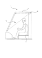
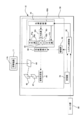
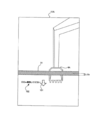
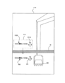
- FIG. 1 It is a mimetic diagram showing a schematic structure of construction machine 1 carrying HUD10 which is one embodiment of a projection type display of the present invention. It is a schematic diagram which shows the internal structural example of the cab 5 in the construction machine 1 shown in FIG. It is a schematic diagram which shows the state which looked at the front windshield 11 from the driver's seat 6 of the cab 5 in the construction machine 1 shown in FIG. It is a schematic diagram which shows the internal structure of HUD10 shown in FIG.1 and FIG.2. It is a functional block diagram of the system control part 60 shown in FIG. It is a figure which shows 11 A of projection ranges observed from the driver's seat 6 (eye box). It is a figure which shows 11 A of projection ranges observed from the driver's seat 6 (eye box).
- FIG. 1 is a schematic diagram showing a schematic configuration of a construction machine 1 equipped with a HUD 10 which is an embodiment of a projection display device of the present invention.
- the construction machine 1 is a hydraulic excavator, and includes a lower traveling body 2, an upper revolving body 3 that is pivotally supported by the lower traveling body 2, and a front working unit 4 that is supported by the upper revolving body 3. It is configured.
- the lower traveling body 2 and the upper swing body 3 constitute a main body of the construction machine 1.
- the lower traveling body 2 includes a metal or rubber crawler for traveling on public roads and work sites.
- the upper swing body 3 includes a driver's cab 5 in which an operating device for operating the front working unit 4 and a driver's seat 6 for a worker to sit are installed, and a structure (for example, a handrail) fixed to the driver's cab 5 Or 31).
- the structure 31 is disposed in front of the front windshield 11 in the cab 5.
- the front working unit 4 is supported by the upper swing body 3 so as to be movable in the direction of gravity and the direction perpendicular to the direction of gravity (the vertical direction in the figure and the direction perpendicular to the paper surface), and the arm 4C supports the arm 4C.
- a boom 4B that is rotatably supported and a bucket 4A that is rotatably supported by the boom 4B with respect to the boom 4B.
- the bucket 4A is a part that can directly contact a work target such as the ground or a load, and constitutes a work machine.
- bucket 4A may replace with the bucket 4A and the structure by which other working machines, such as a steel cutting machine, a concrete crusher, a grasping machine, or a striking-type crushing tool, were mounted on the boom 4B.
- other working machines such as a steel cutting machine, a concrete crusher, a grasping machine, or a striking-type crushing tool, were mounted on the boom 4B.
- the bucket 4A can be moved in the vertical direction in the figure with respect to the cab 5 via the arm 4C and the boom 4B. Further, the bucket 4 ⁇ / b> A is rotatable around the direction of the line of sight of the worker sitting on the driver's seat 6 and the direction orthogonal to the direction of gravity. Further, the boom 4B is rotatable about a direction perpendicular to the paper surface in the drawing.
- the front working unit 4 is provided with a sensor group such as an angular velocity sensor and a three-axis acceleration sensor for detecting the posture of the front working unit 4.
- a sensor group such as an angular velocity sensor and a three-axis acceleration sensor for detecting the posture of the front working unit 4.
- the driver's cab 5 is provided with a front windshield 11 in front of the driver's seat 6, and a part of the front windshield 11 is an area that is processed to reflect image light, which will be described later.
- This region constitutes a projection range 11A as a projection plane on which the image light emitted from the HUD 10 is projected.
- the HUD 10 is installed in the driver's cab 5, and a virtual image is displayed in front of the front windshield 11 by an operator sitting on the driver's seat 6 by image light projected onto a projection range 11 ⁇ / b> A that is a partial area of the front windshield 11. Is displayed so as to be visible.
- FIG. 2 is a schematic diagram showing an example of the internal configuration of the cab 5 in the construction machine 1 shown in FIG.
- the HUD 10 is provided above and behind the worker while the worker is seated on the driver's seat 6.
- An operator of the construction machine 1 projects the information such as icons or characters for supporting the work by the construction machine 1 by viewing the image light projected on the projection range 11A of the front windshield 11 and reflected here. Can be visually recognized.
- the projection range 11A has a function of reflecting image light projected from the HUD 10 and simultaneously transmitting light from the outside (external environment). For this reason, the operator can visually recognize the virtual image based on the image light projected from the HUD 10 so as to overlap the scenery of the outside world.
- the HUD 10 is used by being mounted on a hydraulic excavator in the example of FIG. 1, but a working machine (for example, a wheel loader, a bulldozer, a motor grader, or Forklifts and the like can be mounted in the same manner.
- a working machine for example, a wheel loader, a bulldozer, a motor grader, or Forklifts and the like can be mounted in the same manner.
- FIG. 3 is a schematic view showing a state in which the front windshield 11 is viewed from the driver seat 6 of the cab 5 in the construction machine 1 shown in FIG.
- the cab 5 is surrounded by a front windshield 11, a right side windshield 21, and a left side windshield 22.
- the driver's cab 5 includes a left operation lever 23 for operating bending and extension of the front working unit 4 and turning of the upper revolving unit 3, a right operating lever 24 for operating excavation and opening of the bucket 4A of the front working unit 4, and the like. Is provided around the driver's seat 6.
- the assignment of the operation function to the left operation lever 23 and the right operation lever 24 is an example, and the present invention is not limited to this.
- the front windshield 11 has a projection range 11A on which image light emitted from the HUD 10 is projected.
- the projection range 11A reflects image light and transmits light from the outside (external environment).
- a structure 31 is provided in front of the front windshield 11 and the left side windshield 22, and the structure 31 overlaps the projection range 11 ⁇ / b> A when viewed from the driver seat 6.
- FIG. 4 is a schematic diagram showing the internal configuration of the HUD 10 shown in FIGS. 1 and 2.
- the HUD 10 includes a light source unit 40, a light modulation element 44, a drive unit 45 that drives the light modulation element 44, a projection optical system 46, a diffusion plate 47, a reflection mirror 48, a magnifying mirror 49, and a light source unit 40. And a system control unit 60 that controls the drive unit 45 and a storage unit 70 that can be configured by a storage medium such as a flash memory.
- the light source unit 40 includes a light source controller 40A, an R light source 41r that is a red light source that emits red light, a G light source 41g that is a green light source that emits green light, and a B light source that is a blue light source that emits blue light. 41b, dichroic prism 43, collimator lens 42r provided between R light source 41r and dichroic prism 43, collimator lens 42g provided between G light source 41g and dichroic prism 43, B light source 41b and dichroic prism 43, a collimator lens 42b provided between the two.
- the dichroic prism 43 is an optical member for guiding light emitted from each of the R light source 41r, the G light source 41g, and the B light source 41b to the same optical path. That is, the dichroic prism 43 transmits the red light that has been collimated by the collimator lens 42 r and emits the red light to the light modulation element 44. The dichroic prism 43 reflects the green light that has been collimated by the collimator lens 42 g and emits it to the light modulation element 44. Further, the dichroic prism 43 reflects the blue light that has been collimated by the collimator lens 42 b and emits it to the light modulation element 44.
- the optical member having such a function is not limited to the dichroic prism. For example, a cross dichroic mirror may be used.
- Each of the R light source 41r, the G light source 41g, and the B light source 41b uses a light emitting element such as a laser or an LED (Light Emitting Diode).
- the R light source 41r, the G light source 41g, and the B light source 41b constitute a light source of the HUD 10.
- the light source of the HUD 10 includes three light sources, that is, an R light source 41r, a G light source 41g, and a B light source 41b, but the number of light sources is one, two, or four or more. Also good.
- the light source control unit 40A sets the light emission amount of each of the R light source 41r, the G light source 41g, and the B light source 41b to a predetermined light emission amount pattern, and according to the light emission amount pattern, the R light source 41r, the G light source 41g, and Then, control is performed to sequentially emit light from the B light source 41b.
- the light modulation element 44 spatially modulates the light emitted from the dichroic prism 43 based on the image information, and emits the spatially modulated light (red image light, blue image light, and green image light) to the projection optical system 46. .
- LCOS Liquid crystal on silicon
- DMD Digital Micromirror Device
- MEMS Micro Electro Mechanical Systems
- a liquid crystal display element for example, LCOS (Liquid crystal on silicon), DMD (Digital Micromirror Device), MEMS (Micro Electro Mechanical Systems) element, or a liquid crystal display element can be used.
- the drive unit 45 drives the light modulation element 44 based on the image information input from the system control unit 60, and emits light (red image light, blue image light, and green image light) corresponding to the image information to the light modulation element.
- the light is emitted from 44 toward the projection optical system 46.
- the light modulation element 44 and the drive unit 45 constitute a light modulation unit of the HUD 10.
- the projection optical system 46 is an optical system for projecting the light emitted from the light modulation element 44 onto the diffusion plate 47.
- the optical system is not limited to a lens, and a scanner can also be used.
- the light emitted from the scanning scanner may be diffused by the diffusion plate 47 to form a surface light source.
- the reflection mirror 48 reflects the light diffused by the diffusion plate 47 toward the magnifier 49.
- the magnifying mirror 49 enlarges an image based on the light reflected by the reflecting mirror 48 and projects it on the projection range 11A.
- the light source unit 40, the light modulation element 44, the drive unit 45, the projection optical system 46, the diffusion plate 47, the reflection mirror 48, and the magnifying glass 49 are emitted from the R light source 41r, the G light source 41g, and the B light source 41b.
- a projection display unit 50 that spatially modulates light based on image information input from the system control unit 60, projects image light obtained by the spatial modulation onto the projection range 11A, and displays a virtual image based on the image light.
- the projection range 11 ⁇ / b> A constitutes a display range in which a virtual image can be displayed by the projection display unit 50.
- the system control unit 60 controls the light source control unit 40A and the drive unit 45 to emit image light based on the image information to the diffusion plate 47 via the projection optical system 46.
- the diffusing plate 47, the reflecting mirror 48, and the magnifying glass 49 shown in FIG. 4 allow an image based on the image light projected on the projection range 11A to be visually recognized as a virtual image at a position in front of the front windshield 11. Optical design is made.
- the system control unit 60 is mainly composed of a processor, and includes a ROM (Read Only Memory) storing a program executed by the processor, a RAM (Random Access Memory) as a work memory, and the like.
- ROM Read Only Memory
- RAM Random Access Memory
- the storage unit 70 stores a plurality of work support information.
- the work support information is information that supports efficient work progress by displaying the work support information in the vicinity of the bucket 4A that is often watched during work.
- the work support information is, for example, characters or arrows indicating the excavation direction by the bucket 4A, characters or scales indicating the excavation amount (OOm), warning information for alerting, and the like.
- the sensor group 80 shown in FIG. 4 is a three-axis acceleration sensor, an angular velocity sensor, or the like provided in the front working unit 4.
- the acceleration information and angular velocity information detected by the sensor group 80 are input to the system control unit 60.
- FIG. 5 is a functional block diagram of the system control unit 60 shown in FIG.
- the system control unit 60 includes an attitude detection unit 61, an overlapping range detection unit 62, and a display control unit 63.
- the posture detection unit 61, the overlapping range detection unit 62, and the display control unit 63 are functional blocks formed by the processor of the system control unit 60 executing a program including a control program stored in the ROM.
- the attitude detection unit 61 detects the attitude of the bucket 4A determined by the vertical position of the bucket 4A and the distance of the bucket 4A from the cab 5 based on the acceleration information and the angular velocity information input from the sensor group 80.
- the overlapping range detection unit 62 detects the first overlapping range of the projection range 11A and the bucket 4A observed from the driver's seat 6.
- an eye box is set in advance in the space above the driver's seat 6, and if the operator's eyes are located in the eye box, the operator can view a virtual image displayed by the projection display unit 50. Visible.
- the position of the projection range 11A is fixed. Therefore, if the attitude of the bucket 4A is known, the first overlap between the projection range 11A observed from the driver's seat 6 and the bucket 4A. It is possible to detect a range.
- the storage unit 70 stores a table in which each of the postures that can be taken by the bucket 4A is associated with information on the first overlapping range in the projection range 11A. Then, the overlapping range detection unit 62 detects the first overlapping range based on the attitude of the bucket 4A detected by the attitude detection unit 61 and this table.
- the first overlapping range is detected by analyzing a captured image obtained by imaging the projection range 11A by an imaging device (for example, an imaging device attached to an operator's helmet) installed near the eye box. May be.
- an imaging device for example, an imaging device attached to an operator's helmet
- the display control unit 63 controls the virtual image displayed by the projection display unit 50 by controlling the image information input to the driving unit 45.
- the display control unit 63 causes the projection display unit 50 to display a virtual image based on the work support information by including the work support information read from the storage unit 70 in the image information.
- the distance L between the first overlapping range and the second overlapping range refers to a distance connecting the centers of these two ranges in the direction in which the bucket 4A can move (the direction of gravity and the opposite direction).
- the first control is a control for releasing the maintenance of the positional relationship and displaying the work support information at a position avoiding the second overlapping range, or displaying the work support information while maintaining the positional relationship. Control that makes the size larger than the display size in a state where the distance L exceeds the threshold value th.
- the position of the structure 31 is fixed, the position of the projection range 11A is also fixed, and the position of the eye box is also determined, information on the second overlapping range is stored in the storage unit 70 in advance. be able to.
- 6 to 20 are diagrams showing the projection range 11A observed from the driver's seat 6.
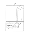
- FIG. 6 shows an example in which the virtual image 101 and the virtual image 102 based on the work support information are observed from the eye box by the image light projected on the projection range 11A.
- the bucket 4A and the structure 31 are observed together from the eye box through the projection range 11A. 6 to 20, the outline of the bucket 4A indicates the first overlapping range, and the outline of the structure 31 indicates the second overlapping range.
- the virtual image 101 is for instructing the start of excavation with an arrow.
- the virtual image 102 is used to instruct the operator to start excavation with characters (in the example of FIG. 6, “Excavate OOm”).
- the display control unit 63 performs follow-up control to display the virtual image 101 and the virtual image 102 in a predetermined positional relationship with respect to the first overlapping range.
- the display control unit 63 displays the virtual image 101 and the virtual image 102 in the display range 111 located on the left side with respect to the bucket 4A.
- the position of the display range 111 is always controlled to a fixed position with respect to the position of the first overlapping range.
- the worker of the construction machine 1 operates the left operation lever 23 from the state shown in FIG. 6 to lower the bucket 4A.
- the state at this time is shown in FIG.
- the display control unit 63 performs follow-up control to display the virtual image 101 and the virtual image 102 in the display range 111 positioned on the left side with respect to the bucket 4A, as in FIG.
- the display control unit 63 causes the first overlapping range (bucket 4A) to follow the movement in the state where the distance L between the first overlapping range and the second overlapping range exceeds the threshold th.
- the display positions of the virtual image 101 and the virtual image 102 are changed, and the positional relationship between the first overlapping range and the display positions of the virtual image 101 and the virtual image 102 is kept constant.
- the operator of the construction machine 1 operates the left operation lever 23 from the state shown in FIG. 7 to further lower the bucket 4A.
- the state at this time is shown in FIG.
- the distance L between the first overlapping range and the second overlapping range changes from a state exceeding the threshold th to a state equal to or less than the threshold th.
- FIG. 8 shows a case where the display control unit 63 performs the first control.
- the display control unit 63 performs the first control so that the virtual image 101 and the virtual image 102 are not displayed in the display range 111 positioned to the left of the first overlapping range, and the first overlapping range is moving. Then, the virtual image 101 and the virtual image 102 are displayed at a position (a position below the structure 31 in FIG. 8) that avoids the second overlapping range.
- the virtual images 101 and 102 displayed near the bucket 4A as shown in FIGS. 6 and 7 jump over the structure 31 as shown in FIG. And move to a position far from the bucket 4A.
- the display control part 63 continues and performs 1st control, and maintains the display position of the virtual image 101 and the virtual image 102 in the same position as the state of FIG.
- the worker of the construction machine 1 operates the left operation lever 23 from the state shown in FIG. 9 to further lower the bucket 4A.
- the state at this time is shown in FIG.
- the display control unit 63 resumes the follow-up control for displaying the virtual image 101 and the virtual image 102 in the display range 111 positioned to the left with respect to the bucket 4A. Tracking control is also performed when the bucket 4A is further lowered from the state shown in FIG. 10, and the virtual image 101 and the virtual image 102 move in accordance with the bucket 4A.
- the virtual images 101 and 102 can be prevented from being blocked by the structure 31, and the visibility of the virtual image is improved to improve work efficiency. be able to.
- the display control unit 63 performs the first control, and changes to FIG. As shown, the virtual image 101 and the virtual image 102 are not displayed in the display range 111 located to the left of the first overlapping range, and the second overlapping range is avoided in the direction in which the first overlapping range is moving.
- the virtual image 101 and the virtual image 102 are displayed at the position (a position below the structure 31).
- the display control unit 63 displays a virtual image 101A that is a copy of the virtual image 101 and a virtual image 102A that is a copy of the virtual image 102 in the display range 111 set in the immediately following tracking control.
- the operator of the construction machine 1 operates the left operation lever 23 from the state shown in FIG. 11 to further lower the bucket 4A.
- the state at this time is shown in FIG.
- the display control part 63 continues and performs 1st control, and maintains the display of the virtual image 101, the virtual image 102, the virtual image 101A, and the virtual image 102A with the state of FIG.
- the worker of the construction machine 1 operates the left operation lever 23 from the state shown in FIG. 12 to further lower the bucket 4A.
- the state at this time is shown in FIG.
- the display control part 63 continues and performs 1st control, and maintains the display of the virtual image 101, the virtual image 102, the virtual image 101A, and the virtual image 102A with the state of FIG. Thereafter, when the bucket 4A is further lowered and the distance L exceeds the threshold th, the display control unit 63 erases the virtual images 101A and 102A displayed in the display range 111 and resumes the follow-up control.
- the virtual images 101 and 102 and the copies of the virtual images 101 and 102 are displayed at positions where they do not overlap the structure 31 while the distance L is equal to or less than the threshold th. Therefore, the visibility of the work support information can be improved and the work efficiency can be improved.
- the display control unit 63 performs the first control and performs the virtual image 101.
- the display position of the virtual image 102 is fixed to the display range 111 set in the immediately preceding tracking control. After that, even if the bucket 4A is further lowered, the display control unit 63 does not change the display positions of the virtual image 101 and the virtual image 102 in a state where the distance L is equal to or less than the threshold th.
- FIG. 14 shows a state in which the bucket 4A is lowered from the state shown in FIG. In this state, the virtual images 101 and 102 remain displayed in the display range 111 set immediately before the distance L reaches the threshold th.
- the operator of the construction machine 1 operates the left operation lever 23 from the state shown in FIG. 14 to further lower the bucket 4A.
- the state at this time is shown in FIG.
- the distance L exceeds the threshold th.
- the display control unit 63 switches from the first control to the follow-up control. Thereby, as shown in FIG. 15, the virtual images 101 and 102 are moved to the display range 111 set to the left of the bucket 4A.
- FIG. 16 shows a state where the bucket 4A is lowered from the state shown in FIG. 7 and the distance L becomes equal to or less than the threshold th.
- the display control unit 63 displays the virtual images 101B and 102B in the display range 111 set at a predetermined position with respect to the first overlapping range.
- the virtual image 101B is a virtual image obtained by enlarging the virtual image 101 shown in FIG. 7, and the virtual image 102B is a virtual image obtained by enlarging the virtual image 102 shown in FIG.
- the worker of the construction machine 1 operates the left operation lever 23 from the state shown in FIG. 16 to further lower the bucket 4A.
- the situation at this time is shown in FIG.
- the distance L between the first overlapping range and the second overlapping range is equal to or less than the threshold th, but the display control unit 63 is set at a predetermined position with respect to the first overlapping range.
- the virtual images 101B and 102B are moved to the display range 111 to be displayed.
- the virtual image 101B and a part of the virtual image 102B are hidden by the structure 31, but the virtual image 101B and the virtual image 102B are larger in size than the virtual image 101 and the virtual image 102. Can be grasped.
- FIG. 18 shows a state where the bucket 4A is further lowered from the state shown in FIG. 17 and the distance L exceeds the threshold th.
- the display control unit 63 causes the virtual images 101 and 102 to be displayed in the display range 111 set at a predetermined position with respect to the first overlapping range. That is, the display size of the virtual image based on the work support information is returned to the original and the tracking control is resumed.
- the virtual image based on the work support information has a larger size than when the distance L exceeds the threshold th. Is displayed. For this reason, even if the bucket 4 ⁇ / b> A overlaps the structure 31, it is possible to prevent most of the virtual image based on the work support information from being hidden by the structure 31. Therefore, it is possible to improve the visibility of the work support information and improve work efficiency.
- the display control unit 63 performs the follow-up control or the first control when the distance L is equal to or less than the threshold th is displayed in the follow-up control performed immediately before the distance L is equal to or less than the threshold th. It is decided according to the contents of the work support information.
- the content of the work support information is, for example, the difference between the width of the virtual image bucket 4A in the moving direction based on the work support information and the width of the second overlapping range (structure 31) in the moving direction of the bucket 4A. It is.
- the content of the work support information is, for example, information indicating whether or not the virtual image based on the work support information is a virtual image based on the warning information.
- the virtual image based on the work support information When tracking control is performed, when the bucket 4A moves across the structure 31, the virtual image based on the work support information also moves across the structure 31. However, if the width in the moving direction of the bucket 4A of the virtual image based on the work support information is sufficiently larger than the width in the moving direction of the bucket 4A in the second overlapping range (structure 31), the virtual image is generated by the follow-up control. Even if it is hidden by the structure 31, the outline of the work support information indicated by the virtual image can be confirmed. For example, when the width of the virtual image bucket 4A in the moving direction based on the work support information is three times the width of the second overlapping range (structure 31) in the moving direction of the bucket 4A, the work support indicated by the virtual image An overview of the information can be confirmed.
- the virtual image is generated by the follow-up control. There may be a period in which the structure 31 is completely hidden, or there may be a period in which most of the virtual image is completely hidden by the structure 31. For this reason, it becomes difficult to convey the work support information indicated by the virtual image to the worker.
- the width in the moving direction of the bucket 4A of the virtual image based on the work support information is equal to or smaller than the width in the moving direction of the bucket 4A in the second overlapping range (structure 31)
- the virtual image is caused by the structure 31 by the tracking control. A period of complete hiding occurs.
- a virtual image based on the warning information is displayed as the work support information
- a period during which the virtual image based on the warning information is hidden by the structure 31 may be generated by the follow-up control. Therefore, the warning information indicated by the virtual image is given to the worker. It becomes difficult to convey.
- the display control unit 63 sets the width of the virtual image being displayed in the moving direction of the bucket 4A to the moving direction of the bucket 4A in the second overlapping range (structure 31). If the width is larger than the width threshold, the follow-up control is continued. On the other hand, when the width of the virtual image being displayed in the moving direction of the bucket 4A is not larger than the width of the second overlapping range (structure 31) in the moving direction of the bucket 4A by the width threshold value, the display control unit 63 Do one control.
- the display control unit 63 continues the tracking control if the virtual image based on the warning information is not displayed, and the first if the virtual image based on the warning information is displayed. Control.
- the width in the moving direction of the bucket 4A is larger than the width in the moving direction of the bucket 4A in the second overlapping range (structure 31) by a width threshold value or more. There is no example.
- FIG. 19 shows a display example of a virtual image in which the width in the moving direction of the bucket 4A is larger than the width in the moving direction of the bucket 4A in the second overlapping range (structure 31) by a width threshold value or more.
- a virtual image 161 with the characters “Please excavate OO m” and a virtual image 162 with an arrow are displayed in the display range 112.
- FIG. 20 is a diagram illustrating a state when the bucket 4A is lowered from the state illustrated in FIG.
- the display range 112 shown in FIG. 19 is moved according to the position of the bucket 4A in FIG. 20, and although the virtual image 161 and a part of the virtual image 162 displayed in the display range 112 are hidden by the structure 31, Its contents can be roughly confirmed.
- the display control unit 63 compares the width in the moving direction of the bucket 4A with the width of the second overlapping range in all virtual images based on the work support information to be displayed in the display ranges 111 and 112 set during the follow-up control.
- the distance L is equal to or less than the threshold th. In this case, it is preferable to perform the first control.
- FIG. 21 is a flowchart for explaining the operation of the system control unit 60 shown in FIG. Note that the processing shown in FIG. 21 is repeatedly executed while the HUD 10 is powered on.
- the display control unit 63 reads work support information from the storage unit 70 (step S1).
- the overlapping range detection unit 62 detects a first overlapping range between the projection range 11A observed from the driver's seat 6 and the bucket 4A based on the posture of the bucket 4A detected by the posture detection unit 61 ( Step S2).
- the display control unit 63 determines whether the distance L between the first overlapping range detected in step S2 and the second overlapping range between the projection range 11A observed from the driver's seat 6 and the structure 31 exceeds the threshold th. If it is determined whether or not the distance L exceeds the threshold th (step S3: YES), follow-up control is performed (step S4), and a virtual image based on the work support information is displayed.
- step S3 NO
- the display control unit 63 improves the visibility of the work support information based on the content of the work support information read from the storage unit 70 in step S1. It is determined whether or not it is necessary to do so (step S5).
- the display control unit 63 performs the first control (step S6) when it is determined from the content of the work support information that the visibility needs to be improved (step S5: YES).
- the display control unit 63 performs follow-up control when it is determined from the content of the work support information that improvement in visibility is not necessary (step S5: NO) (step S7). After step S4, step S6 and step S7, the process returns to step S2.
- the HUD 10 when it can be determined that the bucket 4A approaches the structure 31 and the virtual image based on the work support information may be hidden by the structure 31 when viewed from the driver's seat 6, Based on the content of the support information, it is determined whether the follow-up control is continued or switched to the first control, and necessary control is executed.
- a projection display device mounted on a vehicle having a movable work machine, a main body portion to which the work machine is attached and having a cab, and a structure fixed in front of the cab.
- a projection plane that includes a light modulation unit that spatially modulates light emitted from the light source based on input image information, and that is obtained by spatially modulating the image light obtained by the light modulation unit in the cab
- a projection display unit that projects a virtual image based on the image light, and an overlapping range detection unit that detects a first overlapping range of the projection plane observed from the driver's seat of the cab and the work implement;
- a display control unit that controls the virtual image displayed on the projection display unit by controlling the image information input to the light modulation unit, and the display control unit is the projection plane observed from the driver seat.
- the follow-up display causes the projection display unit to display a virtual image based on work support information while maintaining a predetermined positional relationship with respect to the first overlapping range.
- either the first control or the follow-up control is selected based on the content of the work support information.
- the first control the maintenance of the positional relationship is canceled and the virtual image based on the work support information is displayed at a position avoiding the second overlapping range, or the maintenance of the positional relationship is continued.
- a projection display device that controls the display size of the virtual image based on the work support information to be larger than the display size of the virtual image based on the work support information in a state where the distance exceeds the threshold.
- the projection display device wherein the first control is a virtual image based on the work support information at a position where the maintenance of the positional relationship is canceled and the second overlapping range is avoided.
- the display control unit moves the virtual image based on the work support information in the moving direction of the first overlapping range when the tracking control is switched to the first control.
- a projection display device that displays a virtual image based on the work support information at a position avoiding the second overlapping range.
- the projection display device includes: a light modulation unit that spatially modulates light emitted from a light source based on input image information; and image light obtained by spatial modulation by the light modulation unit.
- a projection display unit that projects onto a projection plane mounted in the operator cab and displays a virtual image based on the image light, and includes a projection display unit that is observed from a driver seat in the operator cab and the working machine.
- An overlapping range detecting step for detecting one overlapping range; and a display control step for controlling a virtual image to be displayed by the projection display unit by controlling the image information input to the light modulation unit, the display control step Then, the driver seat above In a state where the distance between the second overlapping range and the first overlapping range between the projection plane and the structure to be observed exceeds a threshold value, a predetermined positional relationship with respect to the first overlapping range Tracking control for displaying a virtual image based on the work support information on the projection display unit while maintaining the above-mentioned distance, and when the distance changes from a state exceeding the threshold to a state below the threshold, the first control and One of the follow-up controls is selected based on the content of the work support information, and the first control releases the work at a position where the maintenance of the positional relationship is canceled and the second overlapping range is avoided.
- Control of displaying a virtual image based on support information, or a table of virtual images based on the work support information in a state where the distance exceeds the threshold value while maintaining the positional relationship and the virtual image display size based on the work support information The method of the projection display device is controlled to be larger than the size.
- the projection display device includes: a light modulation unit that spatially modulates light emitted from a light source based on input image information; and image light obtained by spatial modulation by the light modulation unit.
- a projection display unit that projects onto a projection plane mounted in the operator cab and displays a virtual image based on the image light, and includes a projection display unit that is observed from a driver seat in the operator cab and the working machine.
- An overlapping range detecting step for detecting one overlapping range
- a display control step for controlling a virtual image to be displayed by the projection display unit by controlling the image information input to the light modulation unit, for causing the computer to execute Blog
- the first Tracking control is performed to display a virtual image based on work support information on the projection display unit while maintaining a predetermined positional relationship with respect to one overlapping range, and the distance is less than or equal to the threshold from the state where the distance exceeds the threshold.
- either the first control or the follow-up control is selected based on the content of the work support information, and the first control cancels the maintenance of the positional relationship.
- Control program of a control projection display device to be larger than the display size of the virtual image based on the work support information in.
- the working efficiency of a vehicle having a work machine can be improved.
Landscapes
- Engineering & Computer Science (AREA)
- Combustion & Propulsion (AREA)
- Mechanical Engineering (AREA)
- Transportation (AREA)
- Chemical & Material Sciences (AREA)
- Physics & Mathematics (AREA)
- General Physics & Mathematics (AREA)
- Optics & Photonics (AREA)
- Civil Engineering (AREA)
- General Engineering & Computer Science (AREA)
- Structural Engineering (AREA)
- Mining & Mineral Resources (AREA)
- Instrument Panels (AREA)
- Component Parts Of Construction Machinery (AREA)
- Controls And Circuits For Display Device (AREA)
Abstract
L'invention concerne : un dispositif d'affichage de type à projection permettant d'améliorer l'efficacité de travail d'un véhicule doté d'une machine de chantier; et un procédé de commande et un programme de commande destinés à ce dernier. Un dispositif d'affichage tête haute (HUD) monté sur une machine de construction (1) comprend : une unité de détection de plage de chevauchement (62) qui détecte une première plage de chevauchement entre une plage de projection (11A) vue depuis un siège de conducteur (6) et un godet (4A); et une unité de commande d'affichage (63). L'unité de commande d'affichage réalise une commande de suivi par laquelle une relation de position prédéterminée par rapport à la première plage de chevauchement est maintenue et une image virtuelle basée sur des informations de support de travail est affichée sur une unité d'affichage de projection (50), dans un état dans lequel la distance L entre la première plage de chevauchement et une seconde plage de chevauchement entre la plage de projection (11A) vue depuis le siège du conducteur (6) et une structure de construction (31) excède une valeur de seuil th. Dans un état dans lequel la distance L n'est pas supérieure à la valeur seuil th, l'unité de commande d'affichage sélectionne et exécute soit la commande de suivi soit une première commande dans laquelle le maintien de la relation de position est annulée et une image virtuelle est affichée à une position autre que la seconde plage de chevauchement.
Priority Applications (3)
| Application Number | Priority Date | Filing Date | Title |
|---|---|---|---|
| JP2018556206A JP6547075B2 (ja) | 2016-12-14 | 2017-10-05 | 投写型表示装置、投写型表示装置の制御方法及び制御プログラム |
| CN201780076717.6A CN110073061A (zh) | 2016-12-14 | 2017-10-05 | 投影型显示装置、投影型显示装置的控制方法及控制程序 |
| US16/423,044 US20190291579A1 (en) | 2016-12-14 | 2019-05-27 | Projection display device, method for controlling projection display device, and program for controlling projection display device |
Applications Claiming Priority (2)
| Application Number | Priority Date | Filing Date | Title |
|---|---|---|---|
| JP2016242628 | 2016-12-14 | ||
| JP2016-242628 | 2016-12-14 |
Related Child Applications (1)
| Application Number | Title | Priority Date | Filing Date |
|---|---|---|---|
| US16/423,044 Continuation US20190291579A1 (en) | 2016-12-14 | 2019-05-27 | Projection display device, method for controlling projection display device, and program for controlling projection display device |
Publications (1)
| Publication Number | Publication Date |
|---|---|
| WO2018110045A1 true WO2018110045A1 (fr) | 2018-06-21 |
Family
ID=62558443
Family Applications (1)
| Application Number | Title | Priority Date | Filing Date |
|---|---|---|---|
| PCT/JP2017/036252 Ceased WO2018110045A1 (fr) | 2016-12-14 | 2017-10-05 | Dispositif d'affichage de type à projection, procédé de commande destiné à un dispositif d'affichage de type à projection et programme de commande |
Country Status (4)
| Country | Link |
|---|---|
| US (1) | US20190291579A1 (fr) |
| JP (1) | JP6547075B2 (fr) |
| CN (1) | CN110073061A (fr) |
| WO (1) | WO2018110045A1 (fr) |
Cited By (1)
| Publication number | Priority date | Publication date | Assignee | Title |
|---|---|---|---|---|
| WO2020183987A1 (fr) * | 2019-03-13 | 2020-09-17 | 日立建機株式会社 | Engin de chantier |
Families Citing this family (4)
| Publication number | Priority date | Publication date | Assignee | Title |
|---|---|---|---|---|
| CN111752046B (zh) * | 2015-10-15 | 2023-06-02 | 麦克赛尔株式会社 | 平视显示装置 |
| CN114207227A (zh) * | 2019-08-06 | 2022-03-18 | 克拉克设备公司 | 集成到门中的显示器 |
| WO2023153722A1 (fr) * | 2022-02-08 | 2023-08-17 | 현대두산인프라코어(주) | Procédé et dispositif d'aide au travail sur la base d'un affichage transparent pour engin de construction |
| US12486645B2 (en) * | 2022-10-28 | 2025-12-02 | Deere & Company | Visibility of work implement using augmented reality |
Citations (2)
| Publication number | Priority date | Publication date | Assignee | Title |
|---|---|---|---|---|
| JP2002194773A (ja) * | 2000-12-26 | 2002-07-10 | Hitachi Constr Mach Co Ltd | 建設機械用キャブ |
| WO2014103498A1 (fr) * | 2012-12-28 | 2014-07-03 | 株式会社小松製作所 | Système d'affichage de machine de construction et procédé de commande associé |
Family Cites Families (5)
| Publication number | Priority date | Publication date | Assignee | Title |
|---|---|---|---|---|
| JP4713600B2 (ja) * | 2008-01-25 | 2011-06-29 | 住友建機株式会社 | 建設機械用表示システム |
| JP5136950B2 (ja) * | 2008-03-25 | 2013-02-06 | 株式会社デンソー | 車載機器の操作装置 |
| JP5426743B1 (ja) * | 2012-10-05 | 2014-02-26 | 株式会社小松製作所 | 掘削機械の表示システム及び掘削機械 |
| US8918246B2 (en) * | 2012-12-27 | 2014-12-23 | Caterpillar Inc. | Augmented reality implement control |
| US10094654B2 (en) * | 2014-08-25 | 2018-10-09 | Trimble Navigation Limited | All-in-one integrated sensing device for machine control |
-
2017
- 2017-10-05 WO PCT/JP2017/036252 patent/WO2018110045A1/fr not_active Ceased
- 2017-10-05 JP JP2018556206A patent/JP6547075B2/ja not_active Expired - Fee Related
- 2017-10-05 CN CN201780076717.6A patent/CN110073061A/zh active Pending
-
2019
- 2019-05-27 US US16/423,044 patent/US20190291579A1/en not_active Abandoned
Patent Citations (2)
| Publication number | Priority date | Publication date | Assignee | Title |
|---|---|---|---|---|
| JP2002194773A (ja) * | 2000-12-26 | 2002-07-10 | Hitachi Constr Mach Co Ltd | 建設機械用キャブ |
| WO2014103498A1 (fr) * | 2012-12-28 | 2014-07-03 | 株式会社小松製作所 | Système d'affichage de machine de construction et procédé de commande associé |
Cited By (9)
| Publication number | Priority date | Publication date | Assignee | Title |
|---|---|---|---|---|
| WO2020183987A1 (fr) * | 2019-03-13 | 2020-09-17 | 日立建機株式会社 | Engin de chantier |
| JP2020148005A (ja) * | 2019-03-13 | 2020-09-17 | 日立建機株式会社 | 作業機械 |
| KR20210034064A (ko) * | 2019-03-13 | 2021-03-29 | 히다찌 겐끼 가부시키가이샤 | 작업 기계 |
| CN112601867A (zh) * | 2019-03-13 | 2021-04-02 | 日立建机株式会社 | 作业机械 |
| CN112601867B (zh) * | 2019-03-13 | 2022-02-25 | 日立建机株式会社 | 作业机械 |
| US11447934B2 (en) | 2019-03-13 | 2022-09-20 | Hitachi Construction Machinery Co., Ltd. | Work machine |
| EP3940156A4 (fr) * | 2019-03-13 | 2022-12-21 | Hitachi Construction Machinery Co., Ltd. | Engin de chantier |
| JP7201486B2 (ja) | 2019-03-13 | 2023-01-10 | 日立建機株式会社 | 作業機械 |
| KR102505529B1 (ko) * | 2019-03-13 | 2023-03-03 | 히다찌 겐끼 가부시키가이샤 | 작업 기계 |
Also Published As
| Publication number | Publication date |
|---|---|
| JP6547075B2 (ja) | 2019-07-17 |
| US20190291579A1 (en) | 2019-09-26 |
| JPWO2018110045A1 (ja) | 2019-10-24 |
| CN110073061A (zh) | 2019-07-30 |
Similar Documents
| Publication | Publication Date | Title |
|---|---|---|
| JP6630855B2 (ja) | 投写型表示装置、投写型表示装置の制御方法、投写型表示装置の制御プログラム | |
| JP6547076B2 (ja) | 投写型表示装置、投写型表示装置の制御方法、投写型表示装置の制御プログラム | |
| JP6582144B2 (ja) | 投写型表示装置、投写型表示装置の制御方法、投写型表示装置の制御プログラム | |
| JP6547075B2 (ja) | 投写型表示装置、投写型表示装置の制御方法及び制御プログラム | |
| JP6271818B2 (ja) | 投写型表示装置及び投写制御方法 | |
| JP6271819B2 (ja) | 投写型表示装置及び投写制御方法 | |
| JP6353989B2 (ja) | 投写型表示装置及び投写制御方法 | |
| JP6236577B2 (ja) | 投写型表示装置及び投写制御方法 | |
| WO2017047132A1 (fr) | Dispositif d'affichage du type à projection et procédé de commande de projection | |
| JP6547077B2 (ja) | 投写型表示装置、投写型表示装置の制御方法、投写型表示装置の制御プログラム | |
| WO2019017040A1 (fr) | Dispositif d'affichage de type à projection, procédé de commande de dispositif d'affichage de type à projection, et programme de commande de dispositif d'affichage de type à projection | |
| JP2020160092A (ja) | 投写型表示装置、投写型表示装置の制御方法、投写型表示装置の制御プログラム | |
| JP2020160094A (ja) | 投写型表示装置、投写型表示装置の制御方法、投写型表示装置の制御プログラム |
Legal Events
| Date | Code | Title | Description |
|---|---|---|---|
| 121 | Ep: the epo has been informed by wipo that ep was designated in this application |
Ref document number: 17881941 Country of ref document: EP Kind code of ref document: A1 |
|
| ENP | Entry into the national phase |
Ref document number: 2018556206 Country of ref document: JP Kind code of ref document: A |
|
| NENP | Non-entry into the national phase |
Ref country code: DE |
|
| 122 | Ep: pct application non-entry in european phase |
Ref document number: 17881941 Country of ref document: EP Kind code of ref document: A1 |