WO2018135376A1 - 車両用サスペンション装置 - Google Patents
車両用サスペンション装置 Download PDFInfo
- Publication number
- WO2018135376A1 WO2018135376A1 PCT/JP2018/000527 JP2018000527W WO2018135376A1 WO 2018135376 A1 WO2018135376 A1 WO 2018135376A1 JP 2018000527 W JP2018000527 W JP 2018000527W WO 2018135376 A1 WO2018135376 A1 WO 2018135376A1
- Authority
- WO
- WIPO (PCT)
- Prior art keywords
- vehicle
- roll center
- suspension
- information
- height
- Prior art date
- Legal status (The legal status is an assumption and is not a legal conclusion. Google has not performed a legal analysis and makes no representation as to the accuracy of the status listed.)
- Ceased
Links
Images



Classifications
-
- B—PERFORMING OPERATIONS; TRANSPORTING
- B60—VEHICLES IN GENERAL
- B60G—VEHICLE SUSPENSION ARRANGEMENTS
- B60G21/00—Interconnection systems for two or more resiliently-suspended wheels, e.g. for stabilising a vehicle body with respect to acceleration, deceleration or centrifugal forces
- B60G21/10—Interconnection systems for two or more resiliently-suspended wheels, e.g. for stabilising a vehicle body with respect to acceleration, deceleration or centrifugal forces not permanently interconnected, e.g. operative only on acceleration, only on deceleration or only at off-straight position of steering
- B60G21/106—Interconnection systems for two or more resiliently-suspended wheels, e.g. for stabilising a vehicle body with respect to acceleration, deceleration or centrifugal forces not permanently interconnected, e.g. operative only on acceleration, only on deceleration or only at off-straight position of steering transversally
-
- B—PERFORMING OPERATIONS; TRANSPORTING
- B60—VEHICLES IN GENERAL
- B60G—VEHICLE SUSPENSION ARRANGEMENTS
- B60G17/00—Resilient suspensions having means for adjusting the spring or vibration-damper characteristics, for regulating the distance between a supporting surface and a sprung part of vehicle or for locking suspension during use to meet varying vehicular or surface conditions, e.g. due to speed or load
- B60G17/015—Resilient suspensions having means for adjusting the spring or vibration-damper characteristics, for regulating the distance between a supporting surface and a sprung part of vehicle or for locking suspension during use to meet varying vehicular or surface conditions, e.g. due to speed or load the regulating means comprising electric or electronic elements
- B60G17/016—Resilient suspensions having means for adjusting the spring or vibration-damper characteristics, for regulating the distance between a supporting surface and a sprung part of vehicle or for locking suspension during use to meet varying vehicular or surface conditions, e.g. due to speed or load the regulating means comprising electric or electronic elements characterised by their responsiveness, when the vehicle is travelling, to specific motion, a specific condition, or driver input
- B60G17/0162—Resilient suspensions having means for adjusting the spring or vibration-damper characteristics, for regulating the distance between a supporting surface and a sprung part of vehicle or for locking suspension during use to meet varying vehicular or surface conditions, e.g. due to speed or load the regulating means comprising electric or electronic elements characterised by their responsiveness, when the vehicle is travelling, to specific motion, a specific condition, or driver input mainly during a motion involving steering operation, e.g. cornering, overtaking
-
- B—PERFORMING OPERATIONS; TRANSPORTING
- B60—VEHICLES IN GENERAL
- B60G—VEHICLE SUSPENSION ARRANGEMENTS
- B60G17/00—Resilient suspensions having means for adjusting the spring or vibration-damper characteristics, for regulating the distance between a supporting surface and a sprung part of vehicle or for locking suspension during use to meet varying vehicular or surface conditions, e.g. due to speed or load
- B60G17/015—Resilient suspensions having means for adjusting the spring or vibration-damper characteristics, for regulating the distance between a supporting surface and a sprung part of vehicle or for locking suspension during use to meet varying vehicular or surface conditions, e.g. due to speed or load the regulating means comprising electric or electronic elements
- B60G17/016—Resilient suspensions having means for adjusting the spring or vibration-damper characteristics, for regulating the distance between a supporting surface and a sprung part of vehicle or for locking suspension during use to meet varying vehicular or surface conditions, e.g. due to speed or load the regulating means comprising electric or electronic elements characterised by their responsiveness, when the vehicle is travelling, to specific motion, a specific condition, or driver input
- B60G17/0165—Resilient suspensions having means for adjusting the spring or vibration-damper characteristics, for regulating the distance between a supporting surface and a sprung part of vehicle or for locking suspension during use to meet varying vehicular or surface conditions, e.g. due to speed or load the regulating means comprising electric or electronic elements characterised by their responsiveness, when the vehicle is travelling, to specific motion, a specific condition, or driver input to an external condition, e.g. rough road surface, side wind
-
- B—PERFORMING OPERATIONS; TRANSPORTING
- B60—VEHICLES IN GENERAL
- B60G—VEHICLE SUSPENSION ARRANGEMENTS
- B60G3/00—Resilient suspensions for a single wheel
- B60G3/18—Resilient suspensions for a single wheel with two or more pivoted arms, e.g. parallelogram
-
- B—PERFORMING OPERATIONS; TRANSPORTING
- B60—VEHICLES IN GENERAL
- B60G—VEHICLE SUSPENSION ARRANGEMENTS
- B60G3/00—Resilient suspensions for a single wheel
- B60G3/18—Resilient suspensions for a single wheel with two or more pivoted arms, e.g. parallelogram
- B60G3/20—Resilient suspensions for a single wheel with two or more pivoted arms, e.g. parallelogram all arms being rigid
-
- B—PERFORMING OPERATIONS; TRANSPORTING
- B60—VEHICLES IN GENERAL
- B60G—VEHICLE SUSPENSION ARRANGEMENTS
- B60G2200/00—Indexing codes relating to suspension types
- B60G2200/10—Independent suspensions
- B60G2200/14—Independent suspensions with lateral arms
-
- B—PERFORMING OPERATIONS; TRANSPORTING
- B60—VEHICLES IN GENERAL
- B60G—VEHICLE SUSPENSION ARRANGEMENTS
- B60G2204/00—Indexing codes related to suspensions per se or to auxiliary parts
- B60G2204/40—Auxiliary suspension parts; Adjustment of suspensions
- B60G2204/424—Mechanisms for force adjustment, e.g. constant force mechanisms
-
- B—PERFORMING OPERATIONS; TRANSPORTING
- B60—VEHICLES IN GENERAL
- B60G—VEHICLE SUSPENSION ARRANGEMENTS
- B60G2204/00—Indexing codes related to suspensions per se or to auxiliary parts
- B60G2204/62—Adjustable continuously, e.g. during driving
-
- B—PERFORMING OPERATIONS; TRANSPORTING
- B60—VEHICLES IN GENERAL
- B60G—VEHICLE SUSPENSION ARRANGEMENTS
- B60G2400/00—Indexing codes relating to detected, measured or calculated conditions or factors
- B60G2400/05—Attitude
- B60G2400/051—Angle
- B60G2400/0511—Roll angle
-
- B—PERFORMING OPERATIONS; TRANSPORTING
- B60—VEHICLES IN GENERAL
- B60G—VEHICLE SUSPENSION ARRANGEMENTS
- B60G2400/00—Indexing codes relating to detected, measured or calculated conditions or factors
- B60G2400/20—Speed
- B60G2400/204—Vehicle speed
-
- B—PERFORMING OPERATIONS; TRANSPORTING
- B60—VEHICLES IN GENERAL
- B60G—VEHICLE SUSPENSION ARRANGEMENTS
- B60G2400/00—Indexing codes relating to detected, measured or calculated conditions or factors
- B60G2400/25—Stroke; Height; Displacement
- B60G2400/252—Stroke; Height; Displacement vertical
-
- B—PERFORMING OPERATIONS; TRANSPORTING
- B60—VEHICLES IN GENERAL
- B60G—VEHICLE SUSPENSION ARRANGEMENTS
- B60G2400/00—Indexing codes relating to detected, measured or calculated conditions or factors
- B60G2400/80—Exterior conditions
- B60G2400/82—Ground surface
-
- B—PERFORMING OPERATIONS; TRANSPORTING
- B60—VEHICLES IN GENERAL
- B60G—VEHICLE SUSPENSION ARRANGEMENTS
- B60G2400/00—Indexing codes relating to detected, measured or calculated conditions or factors
- B60G2400/80—Exterior conditions
- B60G2400/82—Ground surface
- B60G2400/821—Uneven, rough road sensing affecting vehicle body vibration
-
- B—PERFORMING OPERATIONS; TRANSPORTING
- B60—VEHICLES IN GENERAL
- B60G—VEHICLE SUSPENSION ARRANGEMENTS
- B60G2401/00—Indexing codes relating to the type of sensors based on the principle of their operation
- B60G2401/16—GPS track data
-
- B—PERFORMING OPERATIONS; TRANSPORTING
- B60—VEHICLES IN GENERAL
- B60G—VEHICLE SUSPENSION ARRANGEMENTS
- B60G2600/00—Indexing codes relating to particular elements, systems or processes used on suspension systems or suspension control systems
- B60G2600/21—Self-controlled or adjusted
-
- B—PERFORMING OPERATIONS; TRANSPORTING
- B60—VEHICLES IN GENERAL
- B60G—VEHICLE SUSPENSION ARRANGEMENTS
- B60G2800/00—Indexing codes relating to the type of movement or to the condition of the vehicle and to the end result to be achieved by the control action
- B60G2800/01—Attitude or posture control
- B60G2800/012—Rolling condition
Definitions
- the present invention relates to a vehicle suspension device that can adjust the height of a roll center position during traveling.
- Patent Document 1 using a vehicle suspension that can adjust the roll center height of front and rear wheels while maintaining the vehicle height, the front and rear of the suspension mechanism according to changes in the sprung mass and the sprung center of gravity when the vehicle is stopped.
- a desired roll behavior is obtained during turning while the load condition changes.
- FIG. 12 when an external force (lateral force) F y is applied to the wheel, a vertical force F z is generated on the wheel. This vertical force is determined by the angle formed ⁇ and the lateral force F y of the position and the ground roll center C f, of the formula (1).
- F z F y tan ⁇ (1)
- Such a lateral force is generated on a rough road or the like.
- the roll center height is determined in consideration of only the roll behavior during turning, and the vertical force when an external force is applied to the wheels is not taken into account. Resulting in. For example, when the sprung center of gravity increases, the roll center position is raised to change the roll behavior, but the vertical force generated by the external force acting on the wheels increases, so the vehicle is likely to wobble and the steering stability of the vehicle is improved. It will decline.
- An object of the present invention is to provide a vehicle suspension device that solves the above-described problems and can achieve both improvement in steering stability and improvement in vehicle performance.
- the outline of the present invention will be described using reference numerals in the drawings showing embodiments.
- the suspension device for a vehicle includes a suspension 1 that supports a front wheel or a rear wheel so that the roll center height of the vehicle can be adjusted by the actuator 7, and the roll center height of the suspension 1 is set to the height of the actuator 7.
- the vehicle suspension apparatus includes a roll center control unit 16 that adjusts by control, and the roll center control unit 16 includes vehicle speed information that is vehicle speed or vehicle speed estimation information and information related to a traveling road surface.
- the “vehicle speed estimation information” may be information on the speed limit of the road on which the vehicle is running, for example. In this case, it will be used instead of the vehicle speed assuming that the vehicle is traveling at the speed limit.
- the “road surface information” is information for distinguishing, for example, a paved road, a general non-paved road, a road surface with many irregularities, and the like. can get.
- the “predetermined standard” is appropriately determined by design.
- the roll center height of the suspension 1 is controlled in accordance with the traveling state determined from the speed and the road surface state. Therefore, the relationship between the speed information and the road surface information and the roll center height is appropriately set as appropriate, and the roll center height is changed in light of the relationship, the speed information and the road surface information. Steering stability is improved.
- the external force acting on the wheels increases. Therefore, when it is estimated from the vehicle speed information and road surface information that the external force acting on the wheels 8 is large as when traveling on a rough road, the roll center positions of the front and rear wheels are lowered (approached to the ground). Thus, the vertical force acting by the external force acting on the wheel 8 is reduced. By reducing the vertical force acting on each wheel 8, the fluctuation of the vehicle is suppressed and the steering stability of the vehicle is improved.
- the traveling state-corresponding height determining unit 15 includes a traveling state evaluation value calculating unit 11 that calculates an evaluation value of a traveling state based on the vehicle speed information and the road surface information according to a predetermined evaluation criterion, and the unit 11 And roll center position determining means 12 for determining the roll center height of the suspension 1 in accordance with the evaluation value of the running state calculated in (1).
- the evaluation value of the running state is calculated based on the vehicle speed information and the road surface information according to a predetermined evaluation criterion, and the roll center height of the suspension 1 is controlled according to the evaluation value, thereby making it possible to roll more appropriately and easily. Center height can be controlled.
- the “predetermined evaluation criterion” is appropriately determined by design.
- the travel state-corresponding height determining means 15 raises the roll center position as the speed of the vehicle increases during turning, and the lateral force acting on the wheels becomes greater than a predetermined value.
- the roll center height may be determined so as to lower the roll center position. As described above, the vehicle's motion performance is improved by raising the roll center position as the vehicle speed increases during turning.
- the travel state corresponding height determining means 15 may use information acquired from the outside of the vehicle for both or any one of the vehicle information and the road surface information.
- Information acquired from the outside of the vehicle is, for example, road information such as the speed limit of the road that is being obtained from car navigation or ETC (electronic toll system), road traffic information, entrances and exits of highways, GPS (global) Position information using a positioning system).
- road information such as the speed limit of the road that is being obtained from car navigation or ETC (electronic toll system), road traffic information, entrances and exits of highways, GPS (global) Position information using a positioning system).
- the suspension 1 may have a mechanism that makes it possible to adjust the vehicle height during traveling. By simultaneously adjusting the vehicle height and the roll center position of the vehicle, it is possible to more effectively achieve both the vehicle performance and the steering stability.
- a shock absorber unit with a vehicle height adjusting function or the like can be used as the mechanism that enables the vehicle height to be adjusted during the traveling.
- the actuator 7 may use an electric motor 7a as a drive source.
- the actuator 7 can employ a hydraulic device and an electric motor. However, if the electric motor is used, the actuator 7 can be controlled with good responsiveness and finely.
- FIG. 1 is a schematic diagram of a vehicle suspension apparatus according to a first embodiment of the present invention. It is a block diagram which shows the conceptual structure of the roll center control means of the suspension apparatus for vehicles. It is explanatory drawing of the roll center position of the suspension apparatus for vehicles. It is a schematic diagram which shows the roll center position fall state of the suspension apparatus for vehicles. It is explanatory drawing of the roll center position etc.
- the vehicle suspension apparatus includes a suspension 1 and a roll center control means 10 that controls the suspension 1.
- the suspension 1 may be of any type that can support the wheel 8 so that the height of the roll center can be adjusted by the actuator 7, but in this example, a double wishbone type suspension is adopted.
- the knuckle 2 that rotatably supports the wheel 8 is connected to the vehicle body 5 through a pair of upper and lower upper arms 3 and a lower arm 4 of the suspension 1.
- the upper arm 3 and the lower arm 4 are supported so as to be pivotable around the support shaft at the base end so that the vehicle body 5 can swing, and the wheels 8 are moved according to the swinging of the upper arm 3 and the lower arm 4. Stroke up and down.
- a shock absorber unit 6 is connected between the vehicle body 5 and the knuckle 2.
- the shock absorber unit 6 provided between the upper arm 3 and the vehicle body 5 supports the vehicle body 5 so as to be elastically movable up and down, and attenuates the vertical stroke.
- the lower arm 4 is connected to the vehicle body 5 via an actuator 7 whose support point on the vehicle body 5 side can be expanded and contracted in the vehicle body vertical direction. Therefore, the support point on the vehicle body side of the lower arm 4 moves in the vertical direction of the vehicle body according to the expansion and contraction of the actuator 7.
- Actuator 7 is a device in which the movable end connected to the lower arm 4 moves up and down.
- the drive source includes hydraulic equipment such as an electric motor or a hydraulic cylinder.
- the actuator 7 is controlled by the roll center control means 10.
- the actuator 7 includes, for example, an electric motor 7a and a linear motion mechanism 7b that converts forward / reverse rotation of a ball screw mechanism or the like into a linear reciprocating motion as shown in FIG.
- the lower arm 4 is connected to the movable end 7ba of the linear motion mechanism 7b.
- the roll center control means 10 controls a valve (not shown) such as a servo valve provided in the hydraulic path.
- the roll center control means 10 controls the position of the actuator 7 based on information from various sensors.
- the roll center control means 10 is provided as a dedicated ECU (electric control unit) composed of, for example, a computer or as a part of a main ECU (not shown) that performs overall control of the vehicle.
- the left and right actuators 7 and 7 constitute a roll center adjusting means 16.
- the intersection of the extension lines of the upper arm 3 and the lower arm 4 on the right side is the instantaneous rotation center A of the wheel contact point, the instantaneous rotation center A, the right wheel contact point B, and the instantaneous rotation center A ′ on the opposite left and right sides.
- a roll center C is an intersection of straight lines connecting the wheel contact point B ′. That is, the front wheel roll center position Cf (see FIG. 5) and the rear wheel roll center position Cr are adjusted by vertically extending the position of the support point of the lower arm 4 by extending and retracting the actuator 7 with each suspension 1 of four wheels. Can be changed.
- FIG. 4 shows a case where the position of the support point P of the lower arm 4 is lowered by the actuator 7.
- the roll center C * becomes lower than the reference position.
- a straight line connecting the front wheel roll center Cf and the rear wheel roll center Cr becomes the roll axis L.
- the height of the center of gravity is hg
- the point Cg on the roll axis L located directly below the center of gravity G hereinafter referred to as “roll center Cg”
- the height from the ground to the roll center Cg is h Cg
- the center of gravity G The length ⁇ h of the moment arm when a force is applied to is expressed by the following equation (2).
- ⁇ h hg ⁇ h Cg (2)
- Non-Patent Document 1 When an external force (lateral force) is applied to the wheel, a vertical force is generated (see Non-Patent Document 1). Such a lateral force is generated on a rough road or the like.
- Vertical force ⁇ Fz is determined by roll center position C f angle formed between the ground and ⁇ and the lateral force Fy, the formula (4).
- ⁇ Fz Fytan ⁇ (4) That is, the roll center position is lower (closer to the ground) as tan theta decreases, since the vertical force [Delta] F z is reduced, the body is less likely to wander. Therefore, when the external force acting on the wheel such as a bad road becomes large, it is preferable to make the vehicle difficult to wobble by lowering the roll center position, thereby improving the steering stability of the vehicle.
- the roll center control means 10 includes a roll center position determination means 15 that is a height determination means corresponding to a traveling state, and an actuator controller 13.
- the roll center position determining means 15 determines the height h of the roll center position of the suspension 1 according to a predetermined reference based on vehicle speed or vehicle speed information that is estimated information of the vehicle speed and road surface information that is information related to the traveling road surface. c (h Cg , h cf , h cr ) is determined.
- the actuator controller 13 controls to drive and hold the said actuator 7 of the suspension 1 to be roll center height HC g as determined by the roll center position determining means 15.
- the roll center position determining means 15 includes a traveling state evaluation value calculating means 11 for calculating a traveling state evaluation value from the vehicle speed information and road surface information, and the height of the roll center position according to the calculated traveling state evaluation value. h It is comprised with the roll center position determination means 12 which determines Cg .
- the roll center control unit 10 includes a vehicle speed information acquisition unit 17 that acquires vehicle speed information, and a road surface information acquisition unit 18 that acquires road surface information.
- the vehicle speed information acquisition means 17 acquires vehicle speed information by receiving information from the sensor 19 provided in the vehicle or from the outside of the vehicle.
- vehicle speed information is acquired based on road information such as a speed limit of a road that is running from an external information receiving means 20 such as a car navigation system (car navigation device) or an ETC (electronic fee system). You may make it acquire a vehicle speed using the positional information obtained from the said external information receiving means 20.
- the “vehicle speed information” refers to information including the vehicle speed and the road information, but may include only vehicle speed information. *
- the road surface information acquisition means 18 acquires road surface information from a sensor provided in the vehicle or a device capable of receiving information from the outside of the vehicle. For example, the amount of change in the stroke of the suspension 1 (the amount of stroke displacement from the reference position) is monitored by the suspension stroke sensor 21, and road surface information is obtained by judging the unevenness of the road surface based on the amplitude of the amount of stroke change within a certain period of time.
- road surface information may be acquired from vertical acceleration obtained from an acceleration sensor 22 such as a gyro provided in the vehicle.
- road surface information may be acquired based on road information received from the external information receiving means 20 such as car navigation or ETC, similarly to the vehicle speed information.
- the “road surface information” is information indicating the degree of unevenness of the traveling road surface.
- the traveling state evaluation value calculation means 11 calculates a traveling state evaluation value from the vehicle speed information and the road surface information. For example, a running state evaluation value is calculated based on a predetermined map as shown in FIG. 7 from vehicle speed information and road surface information.
- the map shown in the figure is composed of a matrix in which cells are arranged vertically and horizontally, and the cell color is shown darker as the evaluation value increases.
- the traveling state evaluation value is set to a higher value as the vehicle speed obtained from the vehicle speed information is faster and the road surface unevenness obtained from the road surface information is smaller. In this map, when it is determined that the external force acting on the wheel such as a bad road is large, the running state evaluation value ⁇ 0.
- the traveling state evaluation value may be limited so that the traveling state evaluation value ⁇ 0 when the vehicle speed exceeds a certain vehicle speed.
- the running state evaluation value may be calculated from a calculation formula instead of a map.
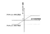
- the roll center position determination means 12 determines the roll center height based on the traveling state evaluation value so that the roll center evaluation value becomes linear with the roll center evaluation value as shown in FIG. 9, for example.
- the running state evaluation value ⁇ 0 it is determined that the roll center position of the front and rear wheels is lowered (closer to the ground). If the running state such that the traveling state evaluation value ⁇ 0 is a case that is traveling on a rough road, the vertical force [Delta] F z an external force acting on the wheel is applied to increase the wheel by the external force is large. Therefore, it lowers the roll center position, to reduce the vertical force [Delta] F z, improve the steering stability of the vehicle by suppressing the fluctuation of the vehicle.
- the actuator controller 13 controls the position of the actuator 7 so as to follow the determination of the roll center position determining means 12.
- the roll center height of the suspension 1 is controlled in accordance with the traveling state determined from the speed and the road surface state. Therefore, the relationship between the speed information and the road surface information and the roll center height is appropriately set to an appropriate relationship in the map or the like, and the roll center height is changed in light of the relationship, the speed information and the road surface information. Thus, the handling stability of the vehicle is improved.
- the external force acting on the wheels 8 increases. Therefore, when it is estimated from the vehicle speed information and road surface information that the external force acting on the wheels 8 is large as when traveling on a rough road, the roll center positions of the front and rear wheels are lowered (approached to the ground). Thus, the vertical force acting by the external force acting on the wheel 8 is reduced. By reducing the vertical force acting on each wheel 8, the fluctuation of the vehicle is suppressed and the steering stability of the vehicle is improved.
- the double wishbone type suspension 1 is adopted.
- the present invention is not limited to this, and the present invention can be applied to any type of suspension as long as the roll center position can be adjusted. be able to.
- the roll center position is adjusted by the suspension 1 for both the front wheel and the rear wheel, but the roll center position may be adjusted by the suspension 1 for only the front wheel or only the rear wheel.
- the roll center position adjustment and the vehicle height adjustment may be combined in combination with a suspension having a vehicle height adjustment function.
- a suspension with a vehicle height adjusting function is a shock absorber that adjusts the vehicle height by changing the overall length as a mechanism that enables the vehicle height to be adjusted during traveling, as in the second embodiment shown in FIG.
- the unit 6A is provided, and the vehicle height control means 26 adjusts the vehicle height during traveling.
- the shock absorber unit 6A with a vehicle height adjusting function has a total length of the shock absorber unit 6A because the movable end is driven forward and backward by a combination of a hydraulic cylinder or an electric motor and a linear motion mechanism in addition to the configuration of the normal shock absorber unit. To change.
- the vehicle height control means 26 is controlled according to the distance between the road surface and the vehicle body by a sensor (not shown) for measuring the distance between the road surface and the vehicle body, a roll rate sensor, or the like.
- the roll center control means 10 takes into account the change in the vehicle height by the control of the vehicle height control means 26 and subtracts, for example, the amount of change in the roll center due to the vehicle height adjustment to perform the roll center control. Done.
Landscapes
- Engineering & Computer Science (AREA)
- Mechanical Engineering (AREA)
- Vehicle Body Suspensions (AREA)
Abstract
操縦安定性の向上と車両の運動性能の向上を両立することができる車両用サスペンション装置を提供する。ロールセンター高さをアクチュエータ(7)の制御によって調整可能なサスペンション(1)と、ロールセンター制御手段(16)を備える。この制御手段(16)は、車速情報と路面情報に基づいて所定の基準によりサスペンション(1)のロールセンター高さを定める走行状態対応高さ決定手段(15)と、この手段(15)により定められたロールセンター高さになるようにアクチュエータ(7)を制御するアクチュエータコントローラ(13)とを備える。
Description
この出願は、2017年1月18日出願の特願2017-006390の優先権を主張するものであり、その全体を参照によりこの出願の一部をなすものとして引用する。
この発明は、走行中にロールセンター位置の高さを調整できる車両用サスペンション装置に関する。
従来、車高を維持したまま前後輪のロールセンター位置の高さ(以下、「ロールセンター高さ」と称することがある)を調整可能な車両用サスペンション装置を用い、車両停止時のバネ上質量及びバネ上重心点の変化に応じて懸架機構における前後輪のロールセンター高さを調整することで、積載条件が変化しても旋回走行時に所望のロール挙動を得ようとするものがある(特許文献1)。
宇野高明著、「車両運動性能とシャシーメカニズム」、第14刷、2014年5月29日、グランプリ出版
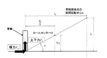
特許文献1では、車高を維持したまま前後輪のロールセンター高さを調整可能な車両用サスペンションを用いて、車両停止時のバネ上質量及びバネ上重心点の変化に応じて懸架機構における前後輪のロールセンター高さを調整することで、積載条件が変化しても旋回走行時に所望のロール挙動を得ようとしている。ここで、図12に示すように、車輪に外力(横力)Fyが加わると車輪に上下力Fzが発生する。この上下力はロールセンターCfの位置と地面との成す角θと横力Fyによって決まり、式(1) で示される。
Fz=Fy tanθ (1)
このような横力は、悪路などで発生する。特許文献1では、旋回走行時のロール挙動のみを考慮してロールセンター高さを決定しており、車輪に外力が加わった際の上下力を考慮していないため、車両の操縦安定性が低下してしまう。
例えば、バネ上重心点が高くなったときにはロールセンター位置を上げてロール挙動を変化させるが、車輪に作用する外力によって発生する上下力が大きくなるため車両がふらつきやすくなり、車両の操縦安定性が低下してしまう。
Fz=Fy tanθ (1)
このような横力は、悪路などで発生する。特許文献1では、旋回走行時のロール挙動のみを考慮してロールセンター高さを決定しており、車輪に外力が加わった際の上下力を考慮していないため、車両の操縦安定性が低下してしまう。
例えば、バネ上重心点が高くなったときにはロールセンター位置を上げてロール挙動を変化させるが、車輪に作用する外力によって発生する上下力が大きくなるため車両がふらつきやすくなり、車両の操縦安定性が低下してしまう。
この発明は、上記課題を解消し、操縦安定性の向上と車両の運動性能の向上を両立することができる車両用サスペンション装置を提供することを目的とする。以下、この発明の概要について、実施形態を示す図面中の符号を用いて説明する。
この発明の車両用サスペンション装置は、車両のロールセンター高さをアクチュエータ7により調整可能なように前輪または後輪を支持するサスペンション1と、このサスペンション1の前記ロールセンター高さを、前記アクチュエータ7の制御によって調整するロールセンター制御手段16とを備える車両用サスペンション装置であって、前記ロールセンター制御手段16は、車速または車速の推定情報である車速情報と、走行している路面に係る情報である路面情報に基づいて所定の基準により前記サスペンション1のロールセンター高さを定める走行状態対応高さ決定手段15と、この手段15により定められたロールセンター高さになるように前記サスペンション1の前記アクチュエータ7を制御するアクチュエータコントローラ13とを備える。
前記「車速の推定情報」は、例えば、走行している道路の制限速度の情報であってもよい。この場合、その制限速度で走行しているであろうとして、車速の代わりに用いることになる。前記「路面情報」は、例えば、舗装路、一般的な非舗装路、凹凸の多い路面等の区別の情報であり、サスペンション1のストロークの変化量や車体の上下方向の加速度等の検出値から得られる。前記「所定の基準」は、設計により適宜定められる。
この構成によると、速度および路面の状態から判る走行状態に応じて、サスペンション1のロールセンター高さが制御される。そのため、速度情報および路面情報とロールセンター高さとの関係を適切な関係に適宜設定しておいて、その関係と速度情報および路面情報とを照らしてロールセンター高さを変更することで、車両の操縦安定性が向上する。
例えば、悪路のような凹凸が大きい路面を走行する場合には、車輪に作用する外力が大きくなる。そのため車速情報と路面情報から、悪路を走行しているときのように車輪8に作用する外力が大きいと推定される場合には、前後輪のロールセンター位置を下降させる(地面に近づける)ことで、車輪8に作用する外力によって作用する上下力を小さくする。各車輪8に作用する上下力を小さくすることで、車両のふらつきを抑え、車両の操縦安定性が向上する。
一方、車両の速度が高い場合には、旋回中の車両には大きな横加速度が作用し、車両横方向の慣性力が大きくなる。そのため車速情報と路面情報から、高い車速で走行しているときのように旋回時に車両横方向の慣性力が大きいと推定される場合には、前後の車輪8のロールセンター位置を上昇させる(地面から遠ざける)ことで、旋回時に車両に作用するロールモーメントを小さくする。旋回時に発生するロールモーメントを小さくすることで、車両のロール量が減少し、旋回内輪の接地性を確保できるため、車両の運動性能が向上する。このように、車両の走行状態に応じてロールセンター高さを調整することで、操縦安定性の向上と車両の運動性能の向上を両立することができる。
この発明において、前記走行状態対応高さ決定手段15は、前記車速情報と前記路面情報に基づいて所定の評価基準により走行状態の評価値を算出する走行状態評価値算出手段11と、この手段11で算出された走行状態の評価値に従って前記サスペンション1のロールセンター高さを定めるロールセンター位置決定手段12とを有するようにしてもよい。上記のように車速情報と路面情報に基づいて所定の評価基準により走行状態の評価値を算出し、この評価値に従ってサスペンション1のロールセンター高さを制御することで、より適切にかつ簡単にロールセンター高さの制御が行える。前記「所定の評価基準」は、設計により適宜定められる。
この発明において、前記走行状態対応高さ決定手段15は、旋回走行時に、車両の速度が速くなるに従ってロールセンター位置を上昇させ、車輪に作用する横力が定められた値よりも大きくなるときはロールセンター位置を下降させるように、前記ロールセンター高さを定めるようにしてもよい。上記のように、旋回走行時に、車両の速度が速くなるに従ってロールセンター位置を上昇させることで、車両の運動性能が向上する。
この発明において、前記走行状態対応高さ決定手段15は、前記車両情報と前記路面情報の両方またはいずれか一方に、車両の外部から取得される情報を利用するようにしてもよい。車両の外部から取得される情報は、例えば、カーナビゲーションやETC(電子料金システム)から得られる走行中の道路の制限速度、道路交通情報、高速道路の出入り口等の道路情報や、GPS(全地球測位システム)等を利用した位置情報である。これらの情報を利用することで、車両が測定手段を持たなくても、前記車両情報や前記路面情報を得ることができる。前記「車速情報」は、車速と前記道路情報を含む情報を言うが、車速の情報のみであってもよい。
この発明において、前記サスペンション1は、走行中に車高の調整を可能にする機構を有していてもよい。車両の車高とロールセンター位置を同時に調整することで、より効果的に車両の運動性能と操縦安定性を両立することができる。前記走行中に車高の調整を可能にする機構としては、車高調整機能付きのショックアブソーバーユニット等を用いることができる。
この発明において、前記アクチュエータ7が電動モータ7aを駆動源とするものであってもよい。前記アクチュエータ7には、油圧式の装置と電動モータとが採用できるが、電動モータであると、応答性良く、かつ細かに制御することが可能である。
請求の範囲および/または明細書および/または図面に開示された少なくとも2つの構成のどのような組み合わせも、この発明に含まれる。特に、請求の範囲の各請求項の2つ以上のどのような組み合わせも、この発明に含まれる。
この発明は、添付の図面を参考にした以下の好適な実施形態の説明から、より明確に理解されるであろう。しかしながら、実施形態および図面は単なる図示および説明のためのものであり、この発明の範囲を定めるために利用されるべきものではない。この発明の範囲は添付の請求の範囲によって定まる。添付図面において、複数の図面における同一の符号は、同一または相当する部分を示す。
この発明の第1実施形態に係る車両用サスペンション装置の模式図である。
同車両用サスペンション装置のロールセンター制御手段の概念構成を示すブロック図である。
同車両用サスペンション装置のロールセンター位置の説明図である。
同車両用サスペンション装置のロールセンター位置下降状態を示す模式図である。
同車両用サスペンション装置を搭載した車両を側方から見たロールセンター位置等の説明図である。
同車両用サスペンション装置の旋回走行状態の動作説明図である。
同車両用サスペンション装置のマップの一例の説明図である。
同車両用サスペンション装置のマップの他の例の説明図である。
同車両用サスペンション装置の走行状態評価値とロールセンター位置との関係を示すグラフである。
同車両用サスペンション装置のアクチュエータの一例の説明図である。
この発明の第2実施形態に係る車両用サスペンション装置を示す模式図である。
ロールセンターの説明図である。
〈第1実施形態について〉
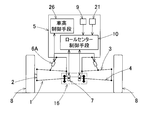
この発明の第1実施形態を図1ないし図9と共に説明する。この車両用サスペンション装置は、サスペンション1と、このサスペンション1を制御するロールセンター制御手段10とで構成される。
この発明の第1実施形態を図1ないし図9と共に説明する。この車両用サスペンション装置は、サスペンション1と、このサスペンション1を制御するロールセンター制御手段10とで構成される。
サスペンション1は、ロールセンター高さをアクチュエータ7により調整可能なように車輪8を支持することができる形式であればよいが、この例では、ダブルウィッシュボーン式サスペンションを採用している。車輪8を回転自在に支持するナックル2は、サスペンション1の上下一対のアッパーアーム3およびロアアーム4を介して車体5に連結されている。アッパーアーム3およびロアアーム4は、車体5側が揺動自在なように、基端で支軸回りに回動自在に支持されており、このアッパーアーム3およびロアアーム4の揺動に応じて車輪8が上下にストロークする。上下一対のアッパーアーム3およびロアアーム4の代わりに、1本のアームが設けられている場合、車体5とナックル2間にショックアブソーバーユニット6が連結される。また、アッパーアーム3と車体5との間に設けられたショックアブソーバーユニット6によって、車体5が弾性的に上下動作可能に支持され、かつその上下方向のストロークが減衰される。ロアアーム4は、車体5側の支持点が、車体上下方向に伸縮可能なアクチュエータ7を介して車体5に連結されている。したがって、ロアアーム4の車体側の支持点はアクチュエータ7の伸縮に応じて車体上下方向に移動する。
アクチュエータ7は、ロアアーム4を連結した可動端が上下に移動する装置である。その駆動源として電動モータもしくは油圧シリンダ等の油圧機器を備える。アクチュエータ7は前記ロールセンター制御手段10によって制御される。電動機を駆動源とする場合は、アクチュエータ7は、例えば、図10に示すように電動モータ7aと、ボールねじ機構等の正逆回転を直線往復動作に変換する直動機構7bとで構成され、直動機構7bの可動端7baにロアアーム4が連結される。アクチュエータ7が油圧シリンダ等の油圧機器である場合、ロールセンター制御手段10は、油圧路に設けられたサーボバルブ等のバルブ(図示せず)を制御する。
ロールセンター制御手段10は、各種センサの情報に基づきアクチュエータ7を位置制御する。ロールセンター制御手段10は、例えばコンピュータからなる専用のECU(エレクトリックコントロールユニット)として、または車両の全体の統括制御を行うメインECU(図示せず)の一部として設けられる。なお、左右のアクチュエータ7,7により、ロールセンター調整手段16が構成される。
ここで、車両の前後輪のロールセンター位置について、図3を用いて説明する。右側のアッパーアーム3およびロアアーム4の各々の延長線の交点が、車輪接地点の瞬間回転中心Aであり、瞬間回転中心Aと右側の車輪接地点B、左右反対側の瞬間回転中心A′と車輪接地点B′とを結んだ直線同士の交点が、ロールセンターCである。すなわち、4輪の各サスペンション1にてアクチュエータ7を伸縮させることで、ロアアーム4の支持点の位置を上下に調整することにより、前輪ロールセンター位置Cf(図5参照)および後輪ロールセンター位置Crを変化させることが可能である。
例えば、アクチュエータ7によってロアアーム4の支持点Pの位置を下降させたときを図4に示す。図4のようにロアアーム4の支持点Pの位置を下降させると、ロールセンターC*が基準位置よりも低くなる。そして、図5に示すように前輪ロールセンターCfと後輪ロールセンターCrを結んだ直線がロール軸Lとなる。重心高さをhg、重心Gの真下に位置するロール軸L上の点Cg(以下、「ロールセンターCg」と称す)、地面からロールセンターCgまでの高さをhCgとすれば、重心Gに力が作用する際のモーメントの腕の長さΔhは、以下の式(2) で示される。
Δh=hg-hCg …(2)
Δh=hg-hCg …(2)
また、図6に示すように、旋回走行時の遠心力Fgyが重心Gに作用するときに、ロールセンターCg周りにロールモーメントMRが発生する。ロールモーメントMRによって、車両全体としてはロール軸L(図5参照)を中心にロール運動をする。ロールモーメントMRは式(3) で示される。
MR=Fgy・Δh …(3)
すなわち、ロールセンター位置が高くなる(地面から遠ざかる)ほどΔhh が小さくなるためロールモーメントMRが小さくなる。従って、車両の速度が高いときのような、旋回時の車両の慣性力(横加速度)が大きくなる場合には、ロールセンター位置を上げることで車両のロール量を小さくすることが望ましい。旋回時のロール量を小さくすることで、旋回内輪の接地性を確保し、車両の運動性能を向上させることができる。
MR=Fgy・Δh …(3)
すなわち、ロールセンター位置が高くなる(地面から遠ざかる)ほどΔhh が小さくなるためロールモーメントMRが小さくなる。従って、車両の速度が高いときのような、旋回時の車両の慣性力(横加速度)が大きくなる場合には、ロールセンター位置を上げることで車両のロール量を小さくすることが望ましい。旋回時のロール量を小さくすることで、旋回内輪の接地性を確保し、車両の運動性能を向上させることができる。
一方、車輪に外力(横力)が加わると上下力が発生する(前記非特許文献1参照)。このような横力は、悪路などで発生する。上下力ΔFzは、ロールセンター位置Cfと地面との成す角θと横力Fyによって決まり、式(4) で示される。
ΔFz=Fytan θ …(4)
すなわち、ロールセンター位置が低くなる(地面に近づく)ほどtan θが小さくなり、上下力ΔFzが小さくなるため、車体がふらつきにくくなる。従って、悪路のような車輪に作用する外力が大きくなる場合には、ロールセンター位置を下げることで車両をふらつき難くすることが好ましく、これにより車両の操縦安定性を向上させることができる。
ΔFz=Fytan θ …(4)
すなわち、ロールセンター位置が低くなる(地面に近づく)ほどtan θが小さくなり、上下力ΔFzが小さくなるため、車体がふらつきにくくなる。従って、悪路のような車輪に作用する外力が大きくなる場合には、ロールセンター位置を下げることで車両をふらつき難くすることが好ましく、これにより車両の操縦安定性を向上させることができる。
〈ロールセンター制御手段10について〉
次に、図2と共に、ロールセンター制御手段10を説明する。ロールセンター制御手段10は、走行状態対応高さ決定手段であるロールセンター位置決定手段15と、アクチュエータコントローラ13とを備える。ロールセンター位置決定手段15は、車速または車速の推定情報である車速情報、および走行している路面に係る情報である路面情報に基づいて所定の基準により前記サスペンション1のロールセンター位置の高さhc(hCg、hcf、hcr)を決定する。アクチュエータコントローラ13は、ロールセンター位置決定手段15により決定されたロールセンター高さHCgになるように前記サスペンション1の前記アクチュエータ7を駆動・保持するように制御する。前記ロールセンター位置決定手段15は、前記車速の情報と路面の情報から走行状態評価値を算出する走行状態評価値算出手段11と、算出された走行状態評価値に応じてロールセンター位置の高さhCgを決定するロールセンター位置決定手段12とで構成される。
次に、図2と共に、ロールセンター制御手段10を説明する。ロールセンター制御手段10は、走行状態対応高さ決定手段であるロールセンター位置決定手段15と、アクチュエータコントローラ13とを備える。ロールセンター位置決定手段15は、車速または車速の推定情報である車速情報、および走行している路面に係る情報である路面情報に基づいて所定の基準により前記サスペンション1のロールセンター位置の高さhc(hCg、hcf、hcr)を決定する。アクチュエータコントローラ13は、ロールセンター位置決定手段15により決定されたロールセンター高さHCgになるように前記サスペンション1の前記アクチュエータ7を駆動・保持するように制御する。前記ロールセンター位置決定手段15は、前記車速の情報と路面の情報から走行状態評価値を算出する走行状態評価値算出手段11と、算出された走行状態評価値に応じてロールセンター位置の高さhCgを決定するロールセンター位置決定手段12とで構成される。
ロールセンター制御手段10は、上記の他に、車速の情報を取得する車速情報取得手段17と、路面の情報を取得する路面情報取得手段18とを備えている。車速情報取得手段17は、車両に備えられたセンサ19もしくは車両外部から情報を受信することで車速情報を取得する。例えば、カーナビ(カーナビゲーション装置)やETC(電子料金システム)等の外部情報受信手段20から走行中の道路の制限速度など、道路情報を基に車速情報を取得する。前記外部情報受信手段20から得られる位置情報を利用して車速を取得するようにしてもよい。前記「車速情報」は、車速と前記道路情報を含む情報を言うが、車速の情報のみでもよい。
路面情報取得手段18は、車両に備えられたセンサもしくは車両外部から情報を受信できる機器から路面情報を取得する。例えば、サスペンション1のストローク変化量(基準位置からのストローク変位量)をサスペンションストロークセンサ21によって監視し、ある時間内のストローク変化量の振幅によって路面の凹凸を判断することで路面情報を取得する。また、車両に備えられたジャイロ等の加速度センサ22から得られる上下加速度から路面情報を取得するものであってもよい。この他に、車速情報と同様に、カーナビやETC等の前記外部情報受信手段20から受信した道路情報を基に路面情報を取得してもよい。前記「路面情報」は、走行している路面の凹凸の程度を示す情報である。
走行状態評価値算出手段11は、前記車速情報と路面情報から走行状態評価値を算出する。例えば、車速の情報と路面の情報から図7のようにあらかじめ定めたマップに基づき走行状態評価値を算出する。同図のマップは、縦横にセルが並ぶマトリクスで構成され、評価値が高くなるに従ってセルの色を濃くして示している。走行状態評価値は、車速の情報から得られる車速が速いほど、また路面情報から得られる路面の凹凸が少ないほど、高い値とされている。このマップにおいて、悪路のような車輪に作用する外力が大きいと判断される場合には走行状態評価値<0とする。一方、車両の速度が高いときのような、旋回時に車両の慣性力が大きいと判断される場合には走行状態評価値>0とする。ここで、図8のように、ある車速以上となったときには走行状態評価値≧0となるように走行状態評価値を制限してもよい。もちろん、マップではなく計算式から走行状態評価値を算出してもよい。
ロールセンター位置決定手段12は、走行状態評価値によって、例えば図9のようにロールセンター評価値と線形の関係になるようにロールセンター高さを決定する。走行状態評価値<0の場合には、前後輪のロールセンター位置を下降させる(地面に近づける)と決定する。走行状態評価値<0となるような走行状態の場合は、悪路を走行しているような場合であり、車輪に作用する外力が大きくその外力によって車輪に作用する上下力ΔFzが大きい。そのため、ロールセンター位置を下降させて、上下力ΔFzを小さくし、車両のふらつきを抑えることで車両の操縦安定性を向上させる。
走行状態評価値>0の場合には、前後輪のロールセンターCf,Cr(図5参照)の高さ位置を上昇させる(地面から遠ざける)と決定する。走行状態評価値>0となるような走行状態の場合は、車両の速度が高いときのような場合であり、旋回時の車両の慣性力(横加速度)が大きくなるためロールモーメントMRが大きくなりロール量も大きい。そのため、ロールセンター位置を上昇させ、ロールモーメントMRを小さくし、車両のロール量を減少させることで旋回内輪の接地性を確保して車両の運動性能を向上させる。なお、走行状態評価値=0となる場合は、ロールセンター位置を基準位置に保つ。
アクチュエータコントローラ13は、ロールセンター位置決定手段12の決定に従うように、アクチュエータ7を位置制御する。
〈作用・効果について〉
上記構成の車両用サスペンション装置によると、速度および路面の状態から判る走行状態に応じて、サスペンション1のロールセンター高さが制御される。そのため、速度情報および路面情報とロールセンター高さとの関係を前記マップ等で適切な関係に適宜設定しておいて、その関係と速度情報および路面情報とを照らし、ロールセンター高さを変更することで、車両の操縦安定性が向上する。
上記構成の車両用サスペンション装置によると、速度および路面の状態から判る走行状態に応じて、サスペンション1のロールセンター高さが制御される。そのため、速度情報および路面情報とロールセンター高さとの関係を前記マップ等で適切な関係に適宜設定しておいて、その関係と速度情報および路面情報とを照らし、ロールセンター高さを変更することで、車両の操縦安定性が向上する。
例えば、悪路のような凹凸が大きい路面を走行する場合には、車輪8に作用する外力が大きくなる。そのため車速情報と路面情報から、悪路を走行しているときのように車輪8に作用する外力が大きいと推定される場合には、前後輪のロールセンター位置を下降させる(地面に近づける)ことで、車輪8に作用する外力によって作用する上下力を小さくする。各車輪8に作用する上下力を小さくすることで、車両のふらつきを抑え、車両の操縦安定性が向上する。
一方、車両の速度が高い場合には、旋回中の車両には大きな横加速度が作用し、車両横方向の慣性力が大きくなる。そのため車速情報と路面情報から、高い車速で走行しているときのように旋回時に車両横方向の慣性力が大きいと推定される場合には、前後の車輪8のロールセンター位置を上昇させる(地面から遠ざける)ことで、旋回時に車両に作用するロールモーメントを小さくする。旋回時に発生するロールモーメントを小さくすることで、車両のロール量が減少し、旋回内輪の接地性を確保できるため、車両の運動性能が向上する。このように、車両の走行状態に応じてロールセンター高さを調整することで、操縦安定性の向上と車両の運動性能の向上を両立することができる。
上記の実施形態では、ダブルウィッシュボーン式のサスペンション1を採用しているが、これに限定されるものではなく、ロールセンター位置を調整できるサスペンションであれば、如何なる形式のサスペンションでもこの発明を適用することができる。また、上記の実施形態では前輪および後輪の両方のサスペンション1によりロールセンター位置を調整するようにしたが、前輪のみまたは後輪のみのサスペンション1によりロールセンター位置を調整するようにしてもよい。
〈第2実施形態について〉
また、車高調整機能付きのサスペンションと組み合わせて、ロールセンター位置の調整と車高調整を組み合わせてもよい。車両の車高とロールセンター位置を同時に調整することで、より効果的に車両の運動性能と操縦安定性を両立することができる。車高調整機能付きのサスペンションは、例えば、図11に示す第2実施形態のように、走行中に車高の調整を可能にする機構として、全長を変化させることで車高を調整するショックアブソーバーユニット6Aを備えた構成とされ、車高制御手段26により走行中に車高調整が行われる。車高調整機能付きのショックアブソーバーユニット6Aは、通常のショックアブソーバーユニットの構成に加えて油圧シリンダまたは電動モータと直動機構からの組み合わせによって、可動端が進退駆動することでショックアブソーバーユニット6Aの全長を変化させる。
また、車高調整機能付きのサスペンションと組み合わせて、ロールセンター位置の調整と車高調整を組み合わせてもよい。車両の車高とロールセンター位置を同時に調整することで、より効果的に車両の運動性能と操縦安定性を両立することができる。車高調整機能付きのサスペンションは、例えば、図11に示す第2実施形態のように、走行中に車高の調整を可能にする機構として、全長を変化させることで車高を調整するショックアブソーバーユニット6Aを備えた構成とされ、車高制御手段26により走行中に車高調整が行われる。車高調整機能付きのショックアブソーバーユニット6Aは、通常のショックアブソーバーユニットの構成に加えて油圧シリンダまたは電動モータと直動機構からの組み合わせによって、可動端が進退駆動することでショックアブソーバーユニット6Aの全長を変化させる。
車高制御手段26は、例えば路面と車体間の距離を計測するセンサ(図示せず)やロールレートセンサ等により、路面と車体間の距離等に応じて制御される。ショックアブソーバーユニット6Aで制御する場合、ロールセンター制御手段10は、車高制御手段26の制御による車高の変化を加味して、例えば車高調整によるロールセンターの変動量だけ差し引いてロールセンター制御が行われる。
以上、この発明を実施するための形態を説明したが、ここで開示した実施形態はすべての点で例示であって制限的なものではない。この発明の範囲は上記した説明ではなくて請求の範囲によって示され、請求の範囲と均等の意味および範囲内でのすべての変更が含まれることが意図される。
1…サスペンション
7…アクチュエータ
2…ナックル
3…アッパーアーム
4…ロアアーム
5…車体
6…ショックアブソーバーユニット
6A…ショックアブソーバーユニット(車高を調整する機構)
7…アクチュエータ
8…車輪
10…ロールセンター制御手段
11…走行状態評価値算出手段
12…ロールセンター位置決定手段
13…アクチュエータコントローラ
15…ロールセンター位置決定手段
17…車速情報取得手段
18…路面情報取得手段
20…外部情報受信手段
7…アクチュエータ
2…ナックル
3…アッパーアーム
4…ロアアーム
5…車体
6…ショックアブソーバーユニット
6A…ショックアブソーバーユニット(車高を調整する機構)
7…アクチュエータ
8…車輪
10…ロールセンター制御手段
11…走行状態評価値算出手段
12…ロールセンター位置決定手段
13…アクチュエータコントローラ
15…ロールセンター位置決定手段
17…車速情報取得手段
18…路面情報取得手段
20…外部情報受信手段
Claims (6)
- 車両のロールセンター高さをアクチュエータにより調整可能なように前輪または後輪を支持するサスペンションと、このサスペンションの前記ロールセンター高さを、前記アクチュエータの制御によって調整するロールセンター制御手段とを備える車両用サスペンション装置であって、
前記ロールセンター制御手段は、
車速または車速の推定情報である車速情報と、走行している路面に係る情報である路面情報とに基づいて所定の基準により前記サスペンションのロールセンター高さを決定する走行状態対応高さ決定手段と、この決定されたロールセンター高さになるように前記サスペンションの前記アクチュエータを制御するアクチュエータコントローラとを備える車両用サスペンション装置。 - 請求項1に記載の車両用サスペンション装置において、前記走行状態対応高さ決定手段は、前記車速情報と前記路面情報に基づいて所定の評価基準により走行状態の評価値を算出する走行状態評価値算出手段と、この手段で算出された走行状態の評価値に従って前記サスペンションのロールセンター高さを定めるロールセンター位置決定手段とを有する車両用サスペンション装置。
- 請求項1または請求項2に記載の車両用サスペンション装置において、前記走行状態対応高さ決定手段は、旋回走行時に、車両の速度が速くなるに従ってロールセンター位置を上昇させ、車輪に作用する横力が定められた値よりも大きくなるときはロールセンター位置を下降させるように、前記ロールセンター高さを定める車両用サスペンション装置。
- 請求項1ないし請求項3のいずれか1項に記載の車両用サスペンション装置において、前記ロールセンター位置決定手段は、前記車両情報と前記路面情報の両方またはいずれか一方に、車両の外部から取得される情報を利用する車両用サスペンション装置。
- 請求項1ないし請求項4のいずれか1項に記載の車両用サスペンション装置において、前記サスペンションは走行中に車高の調整を可能にする機構を有する車両用サスペンション装置。
- 請求項1ないし請求項5のいずれか1項に記載の車両用サスペンション装置において、前記アクチュエータの駆動源が電動モータである車両用サスペンション装置。
Priority Applications (2)
| Application Number | Priority Date | Filing Date | Title |
|---|---|---|---|
| EP18741188.9A EP3572253A4 (en) | 2017-01-18 | 2018-01-11 | VEHICLE SUSPENSION DEVICE |
| US16/511,290 US11001121B2 (en) | 2017-01-18 | 2019-07-15 | Vehicular suspension device |
Applications Claiming Priority (2)
| Application Number | Priority Date | Filing Date | Title |
|---|---|---|---|
| JP2017006390A JP2018114819A (ja) | 2017-01-18 | 2017-01-18 | 車両用サスペンション装置 |
| JP2017-006390 | 2017-01-18 |
Related Child Applications (1)
| Application Number | Title | Priority Date | Filing Date |
|---|---|---|---|
| US16/511,290 Continuation US11001121B2 (en) | 2017-01-18 | 2019-07-15 | Vehicular suspension device |
Publications (1)
| Publication Number | Publication Date |
|---|---|
| WO2018135376A1 true WO2018135376A1 (ja) | 2018-07-26 |
Family
ID=62908094
Family Applications (1)
| Application Number | Title | Priority Date | Filing Date |
|---|---|---|---|
| PCT/JP2018/000527 Ceased WO2018135376A1 (ja) | 2017-01-18 | 2018-01-11 | 車両用サスペンション装置 |
Country Status (4)
| Country | Link |
|---|---|
| US (1) | US11001121B2 (ja) |
| EP (1) | EP3572253A4 (ja) |
| JP (1) | JP2018114819A (ja) |
| WO (1) | WO2018135376A1 (ja) |
Families Citing this family (6)
| Publication number | Priority date | Publication date | Assignee | Title |
|---|---|---|---|---|
| JP2018114819A (ja) * | 2017-01-18 | 2018-07-26 | Ntn株式会社 | 車両用サスペンション装置 |
| CN113365855A (zh) | 2019-01-28 | 2021-09-07 | 日立安斯泰莫株式会社 | 车辆行为装置 |
| GB2601355B (en) * | 2020-11-27 | 2023-09-20 | Jaguar Land Rover Ltd | Slope compensation by moving a vehicle centre of gravity |
| CN114425935A (zh) * | 2021-12-30 | 2022-05-03 | 电子科技大学 | 一种在横坡保持车身水平的主动侧倾系统 |
| CN117755277A (zh) * | 2022-09-16 | 2024-03-26 | 上海汽车集团股份有限公司 | 车辆悬架的控制方法、整车控制器及车辆 |
| CN116653989A (zh) * | 2023-04-14 | 2023-08-29 | 东风汽车集团股份有限公司 | 一种车辆侧倾运动优化控制方法、系统、存储介质及车辆 |
Citations (5)
| Publication number | Priority date | Publication date | Assignee | Title |
|---|---|---|---|---|
| JPS6395908U (ja) * | 1986-12-12 | 1988-06-21 | ||
| JPS6436201U (ja) * | 1987-08-29 | 1989-03-06 | ||
| JPH05213027A (ja) * | 1992-02-06 | 1993-08-24 | Toyota Motor Corp | サスペンション制御装置 |
| JPH05270232A (ja) * | 1992-03-25 | 1993-10-19 | Mazda Motor Corp | 車両のサスペンション装置 |
| JP2007022287A (ja) | 2005-07-15 | 2007-02-01 | Nissan Motor Co Ltd | 車両用サスペンション装置 |
Family Cites Families (21)
| Publication number | Priority date | Publication date | Assignee | Title |
|---|---|---|---|---|
| US4573702A (en) * | 1982-03-23 | 1986-03-04 | Klem Richard H | Anti-pitch suspension |
| JPS6395908A (ja) | 1986-10-07 | 1988-04-26 | エンゲルハード・コーポレーシヨン | 不純粗製カオリン粘土の処理方法 |
| FR2618260B1 (fr) | 1987-07-16 | 1989-10-27 | Portenseigne | Interrupteur micro-onde et ses applications. |
| JP2621525B2 (ja) * | 1989-12-21 | 1997-06-18 | 日産自動車株式会社 | 車両用サスペンション |
| KR19980031242A (ko) * | 1996-10-31 | 1998-07-25 | 오상수 | 자동차의 서스펜션용 유압부시 제어시스템 |
| KR100293680B1 (ko) * | 1997-12-31 | 2001-07-12 | 이계안 | 자동차의 전륜현가장치 |
| JP4586962B2 (ja) * | 2004-04-20 | 2010-11-24 | トヨタ自動車株式会社 | 車両の姿勢制御装置 |
| US7427072B2 (en) * | 2004-06-18 | 2008-09-23 | Bose Corporation | Active vehicle suspension |
| CN102307739B (zh) * | 2009-02-16 | 2014-03-26 | 丰田自动车株式会社 | 车辆的稳定器控制装置 |
| US8670909B2 (en) * | 2009-07-14 | 2014-03-11 | Ford Global Technologies, Llc | Automotive vehicle |
| EP2933161B1 (en) * | 2012-12-11 | 2019-09-25 | Toyota Jidosha Kabushiki Kaisha | Vehicle state detection device |
| WO2014145018A2 (en) * | 2013-03-15 | 2014-09-18 | Levant Power Corporation | Active vehicle suspension improvements |
| JP5955306B2 (ja) * | 2013-12-09 | 2016-07-20 | 本田技研工業株式会社 | 移動車両 |
| US9428242B2 (en) * | 2014-02-24 | 2016-08-30 | Harley-Davidson Motor Company Group, LLC | Variable ride height systems and methods |
| JP6450267B2 (ja) * | 2015-06-23 | 2019-01-09 | 本田技研工業株式会社 | 移動体 |
| JP2018114819A (ja) * | 2017-01-18 | 2018-07-26 | Ntn株式会社 | 車両用サスペンション装置 |
| JP6573082B2 (ja) * | 2017-04-03 | 2019-09-11 | トヨタ自動車株式会社 | 車両のロール制御装置 |
| JP2019001328A (ja) * | 2017-06-16 | 2019-01-10 | Ntn株式会社 | サスペンション制御装置 |
| US10569612B2 (en) * | 2017-12-11 | 2020-02-25 | Cnh Industrial America Llc | Suspension control system providing tire height corrections for an agricultural machine |
| KR102418028B1 (ko) * | 2018-04-06 | 2022-07-06 | 현대자동차주식회사 | 차량 제어 시스템, 차량 제어 시스템의 제어 방법 |
| JP7172414B2 (ja) * | 2018-10-12 | 2022-11-16 | トヨタ自動車株式会社 | 車両用ロール振動制振制御装置 |
-
2017
- 2017-01-18 JP JP2017006390A patent/JP2018114819A/ja active Pending
-
2018
- 2018-01-11 WO PCT/JP2018/000527 patent/WO2018135376A1/ja not_active Ceased
- 2018-01-11 EP EP18741188.9A patent/EP3572253A4/en not_active Withdrawn
-
2019
- 2019-07-15 US US16/511,290 patent/US11001121B2/en active Active
Patent Citations (5)
| Publication number | Priority date | Publication date | Assignee | Title |
|---|---|---|---|---|
| JPS6395908U (ja) * | 1986-12-12 | 1988-06-21 | ||
| JPS6436201U (ja) * | 1987-08-29 | 1989-03-06 | ||
| JPH05213027A (ja) * | 1992-02-06 | 1993-08-24 | Toyota Motor Corp | サスペンション制御装置 |
| JPH05270232A (ja) * | 1992-03-25 | 1993-10-19 | Mazda Motor Corp | 車両のサスペンション装置 |
| JP2007022287A (ja) | 2005-07-15 | 2007-02-01 | Nissan Motor Co Ltd | 車両用サスペンション装置 |
Non-Patent Citations (2)
| Title |
|---|
| See also references of EP3572253A4 * |
| UNO TAKAAKI: "Vehicle movement performance and chassis mechanism", 29 May 2014 |
Also Published As
| Publication number | Publication date |
|---|---|
| US11001121B2 (en) | 2021-05-11 |
| JP2018114819A (ja) | 2018-07-26 |
| EP3572253A4 (en) | 2020-09-30 |
| US20190337351A1 (en) | 2019-11-07 |
| EP3572253A1 (en) | 2019-11-27 |
Similar Documents
| Publication | Publication Date | Title |
|---|---|---|
| WO2018135376A1 (ja) | 車両用サスペンション装置 | |
| US7823673B2 (en) | Variable wheel positioning vehicle | |
| US10639953B2 (en) | Automatic tilting vehicle | |
| EP2423011B1 (en) | Moving mechanism | |
| US20180250998A1 (en) | Wheel Module with Integrated Active Suspension | |
| JPS61150812A (ja) | 後輪のシヨツクアブソ−バ制御装置 | |
| JPH06286447A (ja) | 自動車のサスペンション装置 | |
| JP2009234518A (ja) | アライメント角可変車両 | |
| JP2007518613A (ja) | 車両を懸架するための方法及び装置 | |
| JP2018165060A (ja) | 車両制御装置 | |
| JP5787023B2 (ja) | 車両懸架装置 | |
| JP3807112B2 (ja) | 産業車両の車体揺動制御装置 | |
| JP2894392B2 (ja) | 車両用キャスタ角制御装置 | |
| JP2894393B2 (ja) | 車両用キャスタ角制御装置 | |
| JP2016537237A (ja) | 連結式バス用モータアシストジョイントシステム | |
| JP2580851B2 (ja) | 車両用キャスタ角制御装置 | |
| JP2010234819A (ja) | 車両の後輪操舵制御装置 | |
| JP2011251594A (ja) | 車両用制御装置 | |
| JP2005035486A (ja) | 車両懸架装置 | |
| JP2018069866A (ja) | サスペンション装置 | |
| JP2005178533A (ja) | 車両用サスペンション装置 | |
| KR100559552B1 (ko) | 차량 전륜의 캐스터각 조정 기구 | |
| JP5447189B2 (ja) | 車両用制御装置 | |
| JPS62234708A (ja) | 車両の姿勢制御装置 | |
| CN119590463A (zh) | 轨道车辆的平衡装置、方法、电子设备及存储介质 |
Legal Events
| Date | Code | Title | Description |
|---|---|---|---|
| 121 | Ep: the epo has been informed by wipo that ep was designated in this application |
Ref document number: 18741188 Country of ref document: EP Kind code of ref document: A1 |
|
| NENP | Non-entry into the national phase |
Ref country code: DE |
|
| ENP | Entry into the national phase |
Ref document number: 2018741188 Country of ref document: EP Effective date: 20190819 |