WO2018135376A1 - Dispositif de suspension de véhicule - Google Patents
Dispositif de suspension de véhicule Download PDFInfo
- Publication number
- WO2018135376A1 WO2018135376A1 PCT/JP2018/000527 JP2018000527W WO2018135376A1 WO 2018135376 A1 WO2018135376 A1 WO 2018135376A1 JP 2018000527 W JP2018000527 W JP 2018000527W WO 2018135376 A1 WO2018135376 A1 WO 2018135376A1
- Authority
- WO
- WIPO (PCT)
- Prior art keywords
- vehicle
- roll center
- suspension
- information
- height
- Prior art date
- Legal status (The legal status is an assumption and is not a legal conclusion. Google has not performed a legal analysis and makes no representation as to the accuracy of the status listed.)
- Ceased
Links
Images



Classifications
-
- B—PERFORMING OPERATIONS; TRANSPORTING
- B60—VEHICLES IN GENERAL
- B60G—VEHICLE SUSPENSION ARRANGEMENTS
- B60G21/00—Interconnection systems for two or more resiliently-suspended wheels, e.g. for stabilising a vehicle body with respect to acceleration, deceleration or centrifugal forces
- B60G21/10—Interconnection systems for two or more resiliently-suspended wheels, e.g. for stabilising a vehicle body with respect to acceleration, deceleration or centrifugal forces not permanently interconnected, e.g. operative only on acceleration, only on deceleration or only at off-straight position of steering
- B60G21/106—Interconnection systems for two or more resiliently-suspended wheels, e.g. for stabilising a vehicle body with respect to acceleration, deceleration or centrifugal forces not permanently interconnected, e.g. operative only on acceleration, only on deceleration or only at off-straight position of steering transversally
-
- B—PERFORMING OPERATIONS; TRANSPORTING
- B60—VEHICLES IN GENERAL
- B60G—VEHICLE SUSPENSION ARRANGEMENTS
- B60G17/00—Resilient suspensions having means for adjusting the spring or vibration-damper characteristics, for regulating the distance between a supporting surface and a sprung part of vehicle or for locking suspension during use to meet varying vehicular or surface conditions, e.g. due to speed or load
- B60G17/015—Resilient suspensions having means for adjusting the spring or vibration-damper characteristics, for regulating the distance between a supporting surface and a sprung part of vehicle or for locking suspension during use to meet varying vehicular or surface conditions, e.g. due to speed or load the regulating means comprising electric or electronic elements
- B60G17/016—Resilient suspensions having means for adjusting the spring or vibration-damper characteristics, for regulating the distance between a supporting surface and a sprung part of vehicle or for locking suspension during use to meet varying vehicular or surface conditions, e.g. due to speed or load the regulating means comprising electric or electronic elements characterised by their responsiveness, when the vehicle is travelling, to specific motion, a specific condition, or driver input
- B60G17/0162—Resilient suspensions having means for adjusting the spring or vibration-damper characteristics, for regulating the distance between a supporting surface and a sprung part of vehicle or for locking suspension during use to meet varying vehicular or surface conditions, e.g. due to speed or load the regulating means comprising electric or electronic elements characterised by their responsiveness, when the vehicle is travelling, to specific motion, a specific condition, or driver input mainly during a motion involving steering operation, e.g. cornering, overtaking
-
- B—PERFORMING OPERATIONS; TRANSPORTING
- B60—VEHICLES IN GENERAL
- B60G—VEHICLE SUSPENSION ARRANGEMENTS
- B60G17/00—Resilient suspensions having means for adjusting the spring or vibration-damper characteristics, for regulating the distance between a supporting surface and a sprung part of vehicle or for locking suspension during use to meet varying vehicular or surface conditions, e.g. due to speed or load
- B60G17/015—Resilient suspensions having means for adjusting the spring or vibration-damper characteristics, for regulating the distance between a supporting surface and a sprung part of vehicle or for locking suspension during use to meet varying vehicular or surface conditions, e.g. due to speed or load the regulating means comprising electric or electronic elements
- B60G17/016—Resilient suspensions having means for adjusting the spring or vibration-damper characteristics, for regulating the distance between a supporting surface and a sprung part of vehicle or for locking suspension during use to meet varying vehicular or surface conditions, e.g. due to speed or load the regulating means comprising electric or electronic elements characterised by their responsiveness, when the vehicle is travelling, to specific motion, a specific condition, or driver input
- B60G17/0165—Resilient suspensions having means for adjusting the spring or vibration-damper characteristics, for regulating the distance between a supporting surface and a sprung part of vehicle or for locking suspension during use to meet varying vehicular or surface conditions, e.g. due to speed or load the regulating means comprising electric or electronic elements characterised by their responsiveness, when the vehicle is travelling, to specific motion, a specific condition, or driver input to an external condition, e.g. rough road surface, side wind
-
- B—PERFORMING OPERATIONS; TRANSPORTING
- B60—VEHICLES IN GENERAL
- B60G—VEHICLE SUSPENSION ARRANGEMENTS
- B60G3/00—Resilient suspensions for a single wheel
- B60G3/18—Resilient suspensions for a single wheel with two or more pivoted arms, e.g. parallelogram
-
- B—PERFORMING OPERATIONS; TRANSPORTING
- B60—VEHICLES IN GENERAL
- B60G—VEHICLE SUSPENSION ARRANGEMENTS
- B60G3/00—Resilient suspensions for a single wheel
- B60G3/18—Resilient suspensions for a single wheel with two or more pivoted arms, e.g. parallelogram
- B60G3/20—Resilient suspensions for a single wheel with two or more pivoted arms, e.g. parallelogram all arms being rigid
-
- B—PERFORMING OPERATIONS; TRANSPORTING
- B60—VEHICLES IN GENERAL
- B60G—VEHICLE SUSPENSION ARRANGEMENTS
- B60G2200/00—Indexing codes relating to suspension types
- B60G2200/10—Independent suspensions
- B60G2200/14—Independent suspensions with lateral arms
-
- B—PERFORMING OPERATIONS; TRANSPORTING
- B60—VEHICLES IN GENERAL
- B60G—VEHICLE SUSPENSION ARRANGEMENTS
- B60G2204/00—Indexing codes related to suspensions per se or to auxiliary parts
- B60G2204/40—Auxiliary suspension parts; Adjustment of suspensions
- B60G2204/424—Mechanisms for force adjustment, e.g. constant force mechanisms
-
- B—PERFORMING OPERATIONS; TRANSPORTING
- B60—VEHICLES IN GENERAL
- B60G—VEHICLE SUSPENSION ARRANGEMENTS
- B60G2204/00—Indexing codes related to suspensions per se or to auxiliary parts
- B60G2204/62—Adjustable continuously, e.g. during driving
-
- B—PERFORMING OPERATIONS; TRANSPORTING
- B60—VEHICLES IN GENERAL
- B60G—VEHICLE SUSPENSION ARRANGEMENTS
- B60G2400/00—Indexing codes relating to detected, measured or calculated conditions or factors
- B60G2400/05—Attitude
- B60G2400/051—Angle
- B60G2400/0511—Roll angle
-
- B—PERFORMING OPERATIONS; TRANSPORTING
- B60—VEHICLES IN GENERAL
- B60G—VEHICLE SUSPENSION ARRANGEMENTS
- B60G2400/00—Indexing codes relating to detected, measured or calculated conditions or factors
- B60G2400/20—Speed
- B60G2400/204—Vehicle speed
-
- B—PERFORMING OPERATIONS; TRANSPORTING
- B60—VEHICLES IN GENERAL
- B60G—VEHICLE SUSPENSION ARRANGEMENTS
- B60G2400/00—Indexing codes relating to detected, measured or calculated conditions or factors
- B60G2400/25—Stroke; Height; Displacement
- B60G2400/252—Stroke; Height; Displacement vertical
-
- B—PERFORMING OPERATIONS; TRANSPORTING
- B60—VEHICLES IN GENERAL
- B60G—VEHICLE SUSPENSION ARRANGEMENTS
- B60G2400/00—Indexing codes relating to detected, measured or calculated conditions or factors
- B60G2400/80—Exterior conditions
- B60G2400/82—Ground surface
-
- B—PERFORMING OPERATIONS; TRANSPORTING
- B60—VEHICLES IN GENERAL
- B60G—VEHICLE SUSPENSION ARRANGEMENTS
- B60G2400/00—Indexing codes relating to detected, measured or calculated conditions or factors
- B60G2400/80—Exterior conditions
- B60G2400/82—Ground surface
- B60G2400/821—Uneven, rough road sensing affecting vehicle body vibration
-
- B—PERFORMING OPERATIONS; TRANSPORTING
- B60—VEHICLES IN GENERAL
- B60G—VEHICLE SUSPENSION ARRANGEMENTS
- B60G2401/00—Indexing codes relating to the type of sensors based on the principle of their operation
- B60G2401/16—GPS track data
-
- B—PERFORMING OPERATIONS; TRANSPORTING
- B60—VEHICLES IN GENERAL
- B60G—VEHICLE SUSPENSION ARRANGEMENTS
- B60G2600/00—Indexing codes relating to particular elements, systems or processes used on suspension systems or suspension control systems
- B60G2600/21—Self-controlled or adjusted
-
- B—PERFORMING OPERATIONS; TRANSPORTING
- B60—VEHICLES IN GENERAL
- B60G—VEHICLE SUSPENSION ARRANGEMENTS
- B60G2800/00—Indexing codes relating to the type of movement or to the condition of the vehicle and to the end result to be achieved by the control action
- B60G2800/01—Attitude or posture control
- B60G2800/012—Rolling condition
Definitions
- the present invention relates to a vehicle suspension device that can adjust the height of a roll center position during traveling.
- Patent Document 1 using a vehicle suspension that can adjust the roll center height of front and rear wheels while maintaining the vehicle height, the front and rear of the suspension mechanism according to changes in the sprung mass and the sprung center of gravity when the vehicle is stopped.
- a desired roll behavior is obtained during turning while the load condition changes.
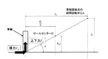
- FIG. 12 when an external force (lateral force) F y is applied to the wheel, a vertical force F z is generated on the wheel. This vertical force is determined by the angle formed ⁇ and the lateral force F y of the position and the ground roll center C f, of the formula (1).
- F z F y tan ⁇ (1)
- Such a lateral force is generated on a rough road or the like.
- the roll center height is determined in consideration of only the roll behavior during turning, and the vertical force when an external force is applied to the wheels is not taken into account. Resulting in. For example, when the sprung center of gravity increases, the roll center position is raised to change the roll behavior, but the vertical force generated by the external force acting on the wheels increases, so the vehicle is likely to wobble and the steering stability of the vehicle is improved. It will decline.
- An object of the present invention is to provide a vehicle suspension device that solves the above-described problems and can achieve both improvement in steering stability and improvement in vehicle performance.
- the outline of the present invention will be described using reference numerals in the drawings showing embodiments.
- the suspension device for a vehicle includes a suspension 1 that supports a front wheel or a rear wheel so that the roll center height of the vehicle can be adjusted by the actuator 7, and the roll center height of the suspension 1 is set to the height of the actuator 7.
- the vehicle suspension apparatus includes a roll center control unit 16 that adjusts by control, and the roll center control unit 16 includes vehicle speed information that is vehicle speed or vehicle speed estimation information and information related to a traveling road surface.
- the “vehicle speed estimation information” may be information on the speed limit of the road on which the vehicle is running, for example. In this case, it will be used instead of the vehicle speed assuming that the vehicle is traveling at the speed limit.
- the “road surface information” is information for distinguishing, for example, a paved road, a general non-paved road, a road surface with many irregularities, and the like. can get.
- the “predetermined standard” is appropriately determined by design.
- the roll center height of the suspension 1 is controlled in accordance with the traveling state determined from the speed and the road surface state. Therefore, the relationship between the speed information and the road surface information and the roll center height is appropriately set as appropriate, and the roll center height is changed in light of the relationship, the speed information and the road surface information. Steering stability is improved.
- the external force acting on the wheels increases. Therefore, when it is estimated from the vehicle speed information and road surface information that the external force acting on the wheels 8 is large as when traveling on a rough road, the roll center positions of the front and rear wheels are lowered (approached to the ground). Thus, the vertical force acting by the external force acting on the wheel 8 is reduced. By reducing the vertical force acting on each wheel 8, the fluctuation of the vehicle is suppressed and the steering stability of the vehicle is improved.
- the traveling state-corresponding height determining unit 15 includes a traveling state evaluation value calculating unit 11 that calculates an evaluation value of a traveling state based on the vehicle speed information and the road surface information according to a predetermined evaluation criterion, and the unit 11 And roll center position determining means 12 for determining the roll center height of the suspension 1 in accordance with the evaluation value of the running state calculated in (1).
- the evaluation value of the running state is calculated based on the vehicle speed information and the road surface information according to a predetermined evaluation criterion, and the roll center height of the suspension 1 is controlled according to the evaluation value, thereby making it possible to roll more appropriately and easily. Center height can be controlled.
- the “predetermined evaluation criterion” is appropriately determined by design.
- the travel state-corresponding height determining means 15 raises the roll center position as the speed of the vehicle increases during turning, and the lateral force acting on the wheels becomes greater than a predetermined value.
- the roll center height may be determined so as to lower the roll center position. As described above, the vehicle's motion performance is improved by raising the roll center position as the vehicle speed increases during turning.
- the travel state corresponding height determining means 15 may use information acquired from the outside of the vehicle for both or any one of the vehicle information and the road surface information.
- Information acquired from the outside of the vehicle is, for example, road information such as the speed limit of the road that is being obtained from car navigation or ETC (electronic toll system), road traffic information, entrances and exits of highways, GPS (global) Position information using a positioning system).
- road information such as the speed limit of the road that is being obtained from car navigation or ETC (electronic toll system), road traffic information, entrances and exits of highways, GPS (global) Position information using a positioning system).
- the suspension 1 may have a mechanism that makes it possible to adjust the vehicle height during traveling. By simultaneously adjusting the vehicle height and the roll center position of the vehicle, it is possible to more effectively achieve both the vehicle performance and the steering stability.
- a shock absorber unit with a vehicle height adjusting function or the like can be used as the mechanism that enables the vehicle height to be adjusted during the traveling.
- the actuator 7 may use an electric motor 7a as a drive source.
- the actuator 7 can employ a hydraulic device and an electric motor. However, if the electric motor is used, the actuator 7 can be controlled with good responsiveness and finely.
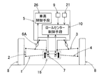
- FIG. 1 is a schematic diagram of a vehicle suspension apparatus according to a first embodiment of the present invention. It is a block diagram which shows the conceptual structure of the roll center control means of the suspension apparatus for vehicles. It is explanatory drawing of the roll center position of the suspension apparatus for vehicles. It is a schematic diagram which shows the roll center position fall state of the suspension apparatus for vehicles. It is explanatory drawing of the roll center position etc.
- the vehicle suspension apparatus includes a suspension 1 and a roll center control means 10 that controls the suspension 1.
- the suspension 1 may be of any type that can support the wheel 8 so that the height of the roll center can be adjusted by the actuator 7, but in this example, a double wishbone type suspension is adopted.
- the knuckle 2 that rotatably supports the wheel 8 is connected to the vehicle body 5 through a pair of upper and lower upper arms 3 and a lower arm 4 of the suspension 1.
- the upper arm 3 and the lower arm 4 are supported so as to be pivotable around the support shaft at the base end so that the vehicle body 5 can swing, and the wheels 8 are moved according to the swinging of the upper arm 3 and the lower arm 4. Stroke up and down.
- a shock absorber unit 6 is connected between the vehicle body 5 and the knuckle 2.
- the shock absorber unit 6 provided between the upper arm 3 and the vehicle body 5 supports the vehicle body 5 so as to be elastically movable up and down, and attenuates the vertical stroke.
- the lower arm 4 is connected to the vehicle body 5 via an actuator 7 whose support point on the vehicle body 5 side can be expanded and contracted in the vehicle body vertical direction. Therefore, the support point on the vehicle body side of the lower arm 4 moves in the vertical direction of the vehicle body according to the expansion and contraction of the actuator 7.
- Actuator 7 is a device in which the movable end connected to the lower arm 4 moves up and down.
- the drive source includes hydraulic equipment such as an electric motor or a hydraulic cylinder.
- the actuator 7 is controlled by the roll center control means 10.
- the actuator 7 includes, for example, an electric motor 7a and a linear motion mechanism 7b that converts forward / reverse rotation of a ball screw mechanism or the like into a linear reciprocating motion as shown in FIG.
- the lower arm 4 is connected to the movable end 7ba of the linear motion mechanism 7b.
- the roll center control means 10 controls a valve (not shown) such as a servo valve provided in the hydraulic path.
- the roll center control means 10 controls the position of the actuator 7 based on information from various sensors.
- the roll center control means 10 is provided as a dedicated ECU (electric control unit) composed of, for example, a computer or as a part of a main ECU (not shown) that performs overall control of the vehicle.
- the left and right actuators 7 and 7 constitute a roll center adjusting means 16.
- the intersection of the extension lines of the upper arm 3 and the lower arm 4 on the right side is the instantaneous rotation center A of the wheel contact point, the instantaneous rotation center A, the right wheel contact point B, and the instantaneous rotation center A ′ on the opposite left and right sides.
- a roll center C is an intersection of straight lines connecting the wheel contact point B ′. That is, the front wheel roll center position Cf (see FIG. 5) and the rear wheel roll center position Cr are adjusted by vertically extending the position of the support point of the lower arm 4 by extending and retracting the actuator 7 with each suspension 1 of four wheels. Can be changed.
- FIG. 4 shows a case where the position of the support point P of the lower arm 4 is lowered by the actuator 7.
- the roll center C * becomes lower than the reference position.
- a straight line connecting the front wheel roll center Cf and the rear wheel roll center Cr becomes the roll axis L.
- the height of the center of gravity is hg
- the point Cg on the roll axis L located directly below the center of gravity G hereinafter referred to as “roll center Cg”
- the height from the ground to the roll center Cg is h Cg
- the center of gravity G The length ⁇ h of the moment arm when a force is applied to is expressed by the following equation (2).
- ⁇ h hg ⁇ h Cg (2)
- Non-Patent Document 1 When an external force (lateral force) is applied to the wheel, a vertical force is generated (see Non-Patent Document 1). Such a lateral force is generated on a rough road or the like.
- Vertical force ⁇ Fz is determined by roll center position C f angle formed between the ground and ⁇ and the lateral force Fy, the formula (4).
- ⁇ Fz Fytan ⁇ (4) That is, the roll center position is lower (closer to the ground) as tan theta decreases, since the vertical force [Delta] F z is reduced, the body is less likely to wander. Therefore, when the external force acting on the wheel such as a bad road becomes large, it is preferable to make the vehicle difficult to wobble by lowering the roll center position, thereby improving the steering stability of the vehicle.
- the roll center control means 10 includes a roll center position determination means 15 that is a height determination means corresponding to a traveling state, and an actuator controller 13.
- the roll center position determining means 15 determines the height h of the roll center position of the suspension 1 according to a predetermined reference based on vehicle speed or vehicle speed information that is estimated information of the vehicle speed and road surface information that is information related to the traveling road surface. c (h Cg , h cf , h cr ) is determined.
- the actuator controller 13 controls to drive and hold the said actuator 7 of the suspension 1 to be roll center height HC g as determined by the roll center position determining means 15.
- the roll center position determining means 15 includes a traveling state evaluation value calculating means 11 for calculating a traveling state evaluation value from the vehicle speed information and road surface information, and the height of the roll center position according to the calculated traveling state evaluation value. h It is comprised with the roll center position determination means 12 which determines Cg .
- the roll center control unit 10 includes a vehicle speed information acquisition unit 17 that acquires vehicle speed information, and a road surface information acquisition unit 18 that acquires road surface information.
- the vehicle speed information acquisition means 17 acquires vehicle speed information by receiving information from the sensor 19 provided in the vehicle or from the outside of the vehicle.
- vehicle speed information is acquired based on road information such as a speed limit of a road that is running from an external information receiving means 20 such as a car navigation system (car navigation device) or an ETC (electronic fee system). You may make it acquire a vehicle speed using the positional information obtained from the said external information receiving means 20.
- the “vehicle speed information” refers to information including the vehicle speed and the road information, but may include only vehicle speed information. *
- the road surface information acquisition means 18 acquires road surface information from a sensor provided in the vehicle or a device capable of receiving information from the outside of the vehicle. For example, the amount of change in the stroke of the suspension 1 (the amount of stroke displacement from the reference position) is monitored by the suspension stroke sensor 21, and road surface information is obtained by judging the unevenness of the road surface based on the amplitude of the amount of stroke change within a certain period of time.
- road surface information may be acquired from vertical acceleration obtained from an acceleration sensor 22 such as a gyro provided in the vehicle.
- road surface information may be acquired based on road information received from the external information receiving means 20 such as car navigation or ETC, similarly to the vehicle speed information.
- the “road surface information” is information indicating the degree of unevenness of the traveling road surface.
- the traveling state evaluation value calculation means 11 calculates a traveling state evaluation value from the vehicle speed information and the road surface information. For example, a running state evaluation value is calculated based on a predetermined map as shown in FIG. 7 from vehicle speed information and road surface information.
- the map shown in the figure is composed of a matrix in which cells are arranged vertically and horizontally, and the cell color is shown darker as the evaluation value increases.
- the traveling state evaluation value is set to a higher value as the vehicle speed obtained from the vehicle speed information is faster and the road surface unevenness obtained from the road surface information is smaller. In this map, when it is determined that the external force acting on the wheel such as a bad road is large, the running state evaluation value ⁇ 0.
- the traveling state evaluation value may be limited so that the traveling state evaluation value ⁇ 0 when the vehicle speed exceeds a certain vehicle speed.
- the running state evaluation value may be calculated from a calculation formula instead of a map.
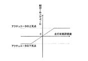
- the roll center position determination means 12 determines the roll center height based on the traveling state evaluation value so that the roll center evaluation value becomes linear with the roll center evaluation value as shown in FIG. 9, for example.
- the running state evaluation value ⁇ 0 it is determined that the roll center position of the front and rear wheels is lowered (closer to the ground). If the running state such that the traveling state evaluation value ⁇ 0 is a case that is traveling on a rough road, the vertical force [Delta] F z an external force acting on the wheel is applied to increase the wheel by the external force is large. Therefore, it lowers the roll center position, to reduce the vertical force [Delta] F z, improve the steering stability of the vehicle by suppressing the fluctuation of the vehicle.
- the actuator controller 13 controls the position of the actuator 7 so as to follow the determination of the roll center position determining means 12.
- the roll center height of the suspension 1 is controlled in accordance with the traveling state determined from the speed and the road surface state. Therefore, the relationship between the speed information and the road surface information and the roll center height is appropriately set to an appropriate relationship in the map or the like, and the roll center height is changed in light of the relationship, the speed information and the road surface information. Thus, the handling stability of the vehicle is improved.
- the external force acting on the wheels 8 increases. Therefore, when it is estimated from the vehicle speed information and road surface information that the external force acting on the wheels 8 is large as when traveling on a rough road, the roll center positions of the front and rear wheels are lowered (approached to the ground). Thus, the vertical force acting by the external force acting on the wheel 8 is reduced. By reducing the vertical force acting on each wheel 8, the fluctuation of the vehicle is suppressed and the steering stability of the vehicle is improved.
- the double wishbone type suspension 1 is adopted.
- the present invention is not limited to this, and the present invention can be applied to any type of suspension as long as the roll center position can be adjusted. be able to.
- the roll center position is adjusted by the suspension 1 for both the front wheel and the rear wheel, but the roll center position may be adjusted by the suspension 1 for only the front wheel or only the rear wheel.
- the roll center position adjustment and the vehicle height adjustment may be combined in combination with a suspension having a vehicle height adjustment function.
- a suspension with a vehicle height adjusting function is a shock absorber that adjusts the vehicle height by changing the overall length as a mechanism that enables the vehicle height to be adjusted during traveling, as in the second embodiment shown in FIG.
- the unit 6A is provided, and the vehicle height control means 26 adjusts the vehicle height during traveling.
- the shock absorber unit 6A with a vehicle height adjusting function has a total length of the shock absorber unit 6A because the movable end is driven forward and backward by a combination of a hydraulic cylinder or an electric motor and a linear motion mechanism in addition to the configuration of the normal shock absorber unit. To change.
- the vehicle height control means 26 is controlled according to the distance between the road surface and the vehicle body by a sensor (not shown) for measuring the distance between the road surface and the vehicle body, a roll rate sensor, or the like.
- the roll center control means 10 takes into account the change in the vehicle height by the control of the vehicle height control means 26 and subtracts, for example, the amount of change in the roll center due to the vehicle height adjustment to perform the roll center control. Done.
Landscapes
- Engineering & Computer Science (AREA)
- Mechanical Engineering (AREA)
- Vehicle Body Suspensions (AREA)
Abstract
L'invention concerne un dispositif de suspension de véhicule grâce auquel l'amélioration de la stabilité de manoeuvre et l'amélioration de performance de conduite de véhicule peuvent être obtenues. Ce dispositif de suspension de véhicule est équipé d'une suspension (1) dont la hauteur de centre de roulis peut être réglée par la commande d'un actionneur (7), et d'un moyen de contrôle de centre de roulis (16). Ce moyen de contrôle (16) est équipé: d'un moyen de détermination de hauteur correspondant à l'état de déplacement (15) qui, sur la base d'information de vitesse de véhicule et d'information de surface de route, détermine la hauteur de centre de roulis de la suspension (1) selon une référence prescrite; et d'un dispositif de commande d'actionneur (13) qui commande l'actionneur (7) de sorte que la hauteur de centre de roulis déterminée par le moyen (15) soit obtenue.
Priority Applications (2)
| Application Number | Priority Date | Filing Date | Title |
|---|---|---|---|
| EP18741188.9A EP3572253A4 (fr) | 2017-01-18 | 2018-01-11 | Dispositif de suspension de véhicule |
| US16/511,290 US11001121B2 (en) | 2017-01-18 | 2019-07-15 | Vehicular suspension device |
Applications Claiming Priority (2)
| Application Number | Priority Date | Filing Date | Title |
|---|---|---|---|
| JP2017006390A JP2018114819A (ja) | 2017-01-18 | 2017-01-18 | 車両用サスペンション装置 |
| JP2017-006390 | 2017-01-18 |
Related Child Applications (1)
| Application Number | Title | Priority Date | Filing Date |
|---|---|---|---|
| US16/511,290 Continuation US11001121B2 (en) | 2017-01-18 | 2019-07-15 | Vehicular suspension device |
Publications (1)
| Publication Number | Publication Date |
|---|---|
| WO2018135376A1 true WO2018135376A1 (fr) | 2018-07-26 |
Family
ID=62908094
Family Applications (1)
| Application Number | Title | Priority Date | Filing Date |
|---|---|---|---|
| PCT/JP2018/000527 Ceased WO2018135376A1 (fr) | 2017-01-18 | 2018-01-11 | Dispositif de suspension de véhicule |
Country Status (4)
| Country | Link |
|---|---|
| US (1) | US11001121B2 (fr) |
| EP (1) | EP3572253A4 (fr) |
| JP (1) | JP2018114819A (fr) |
| WO (1) | WO2018135376A1 (fr) |
Families Citing this family (6)
| Publication number | Priority date | Publication date | Assignee | Title |
|---|---|---|---|---|
| JP2018114819A (ja) * | 2017-01-18 | 2018-07-26 | Ntn株式会社 | 車両用サスペンション装置 |
| CN113365855A (zh) | 2019-01-28 | 2021-09-07 | 日立安斯泰莫株式会社 | 车辆行为装置 |
| GB2601355B (en) * | 2020-11-27 | 2023-09-20 | Jaguar Land Rover Ltd | Slope compensation by moving a vehicle centre of gravity |
| CN114425935A (zh) * | 2021-12-30 | 2022-05-03 | 电子科技大学 | 一种在横坡保持车身水平的主动侧倾系统 |
| CN117755277A (zh) * | 2022-09-16 | 2024-03-26 | 上海汽车集团股份有限公司 | 车辆悬架的控制方法、整车控制器及车辆 |
| CN116653989A (zh) * | 2023-04-14 | 2023-08-29 | 东风汽车集团股份有限公司 | 一种车辆侧倾运动优化控制方法、系统、存储介质及车辆 |
Citations (5)
| Publication number | Priority date | Publication date | Assignee | Title |
|---|---|---|---|---|
| JPS6395908U (fr) * | 1986-12-12 | 1988-06-21 | ||
| JPS6436201U (fr) * | 1987-08-29 | 1989-03-06 | ||
| JPH05213027A (ja) * | 1992-02-06 | 1993-08-24 | Toyota Motor Corp | サスペンション制御装置 |
| JPH05270232A (ja) * | 1992-03-25 | 1993-10-19 | Mazda Motor Corp | 車両のサスペンション装置 |
| JP2007022287A (ja) | 2005-07-15 | 2007-02-01 | Nissan Motor Co Ltd | 車両用サスペンション装置 |
Family Cites Families (21)
| Publication number | Priority date | Publication date | Assignee | Title |
|---|---|---|---|---|
| US4573702A (en) * | 1982-03-23 | 1986-03-04 | Klem Richard H | Anti-pitch suspension |
| JPS6395908A (ja) | 1986-10-07 | 1988-04-26 | エンゲルハード・コーポレーシヨン | 不純粗製カオリン粘土の処理方法 |
| FR2618260B1 (fr) | 1987-07-16 | 1989-10-27 | Portenseigne | Interrupteur micro-onde et ses applications. |
| JP2621525B2 (ja) * | 1989-12-21 | 1997-06-18 | 日産自動車株式会社 | 車両用サスペンション |
| KR19980031242A (ko) * | 1996-10-31 | 1998-07-25 | 오상수 | 자동차의 서스펜션용 유압부시 제어시스템 |
| KR100293680B1 (ko) * | 1997-12-31 | 2001-07-12 | 이계안 | 자동차의 전륜현가장치 |
| JP4586962B2 (ja) * | 2004-04-20 | 2010-11-24 | トヨタ自動車株式会社 | 車両の姿勢制御装置 |
| US7427072B2 (en) * | 2004-06-18 | 2008-09-23 | Bose Corporation | Active vehicle suspension |
| CN102307739B (zh) * | 2009-02-16 | 2014-03-26 | 丰田自动车株式会社 | 车辆的稳定器控制装置 |
| US8670909B2 (en) * | 2009-07-14 | 2014-03-11 | Ford Global Technologies, Llc | Automotive vehicle |
| EP2933161B1 (fr) * | 2012-12-11 | 2019-09-25 | Toyota Jidosha Kabushiki Kaisha | Dispositif de détection d'état de véhicule |
| WO2014145018A2 (fr) * | 2013-03-15 | 2014-09-18 | Levant Power Corporation | Améliorations apportées à la suspension active d'un véhicule |
| JP5955306B2 (ja) * | 2013-12-09 | 2016-07-20 | 本田技研工業株式会社 | 移動車両 |
| US9428242B2 (en) * | 2014-02-24 | 2016-08-30 | Harley-Davidson Motor Company Group, LLC | Variable ride height systems and methods |
| JP6450267B2 (ja) * | 2015-06-23 | 2019-01-09 | 本田技研工業株式会社 | 移動体 |
| JP2018114819A (ja) * | 2017-01-18 | 2018-07-26 | Ntn株式会社 | 車両用サスペンション装置 |
| JP6573082B2 (ja) * | 2017-04-03 | 2019-09-11 | トヨタ自動車株式会社 | 車両のロール制御装置 |
| JP2019001328A (ja) * | 2017-06-16 | 2019-01-10 | Ntn株式会社 | サスペンション制御装置 |
| US10569612B2 (en) * | 2017-12-11 | 2020-02-25 | Cnh Industrial America Llc | Suspension control system providing tire height corrections for an agricultural machine |
| KR102418028B1 (ko) * | 2018-04-06 | 2022-07-06 | 현대자동차주식회사 | 차량 제어 시스템, 차량 제어 시스템의 제어 방법 |
| JP7172414B2 (ja) * | 2018-10-12 | 2022-11-16 | トヨタ自動車株式会社 | 車両用ロール振動制振制御装置 |
-
2017
- 2017-01-18 JP JP2017006390A patent/JP2018114819A/ja active Pending
-
2018
- 2018-01-11 WO PCT/JP2018/000527 patent/WO2018135376A1/fr not_active Ceased
- 2018-01-11 EP EP18741188.9A patent/EP3572253A4/fr not_active Withdrawn
-
2019
- 2019-07-15 US US16/511,290 patent/US11001121B2/en active Active
Patent Citations (5)
| Publication number | Priority date | Publication date | Assignee | Title |
|---|---|---|---|---|
| JPS6395908U (fr) * | 1986-12-12 | 1988-06-21 | ||
| JPS6436201U (fr) * | 1987-08-29 | 1989-03-06 | ||
| JPH05213027A (ja) * | 1992-02-06 | 1993-08-24 | Toyota Motor Corp | サスペンション制御装置 |
| JPH05270232A (ja) * | 1992-03-25 | 1993-10-19 | Mazda Motor Corp | 車両のサスペンション装置 |
| JP2007022287A (ja) | 2005-07-15 | 2007-02-01 | Nissan Motor Co Ltd | 車両用サスペンション装置 |
Non-Patent Citations (2)
| Title |
|---|
| See also references of EP3572253A4 * |
| UNO TAKAAKI: "Vehicle movement performance and chassis mechanism", 29 May 2014 |
Also Published As
| Publication number | Publication date |
|---|---|
| US11001121B2 (en) | 2021-05-11 |
| JP2018114819A (ja) | 2018-07-26 |
| EP3572253A4 (fr) | 2020-09-30 |
| US20190337351A1 (en) | 2019-11-07 |
| EP3572253A1 (fr) | 2019-11-27 |
Similar Documents
| Publication | Publication Date | Title |
|---|---|---|
| WO2018135376A1 (fr) | Dispositif de suspension de véhicule | |
| US7823673B2 (en) | Variable wheel positioning vehicle | |
| US10639953B2 (en) | Automatic tilting vehicle | |
| EP2423011B1 (fr) | Mécanisme mobile | |
| US20180250998A1 (en) | Wheel Module with Integrated Active Suspension | |
| JPS61150812A (ja) | 後輪のシヨツクアブソ−バ制御装置 | |
| JPH06286447A (ja) | 自動車のサスペンション装置 | |
| JP2009234518A (ja) | アライメント角可変車両 | |
| JP2007518613A (ja) | 車両を懸架するための方法及び装置 | |
| JP2018165060A (ja) | 車両制御装置 | |
| JP5787023B2 (ja) | 車両懸架装置 | |
| JP3807112B2 (ja) | 産業車両の車体揺動制御装置 | |
| JP2894392B2 (ja) | 車両用キャスタ角制御装置 | |
| JP2894393B2 (ja) | 車両用キャスタ角制御装置 | |
| JP2016537237A (ja) | 連結式バス用モータアシストジョイントシステム | |
| JP2580851B2 (ja) | 車両用キャスタ角制御装置 | |
| JP2010234819A (ja) | 車両の後輪操舵制御装置 | |
| JP2011251594A (ja) | 車両用制御装置 | |
| JP2005035486A (ja) | 車両懸架装置 | |
| JP2018069866A (ja) | サスペンション装置 | |
| JP2005178533A (ja) | 車両用サスペンション装置 | |
| KR100559552B1 (ko) | 차량 전륜의 캐스터각 조정 기구 | |
| JP5447189B2 (ja) | 車両用制御装置 | |
| JPS62234708A (ja) | 車両の姿勢制御装置 | |
| CN119590463A (zh) | 轨道车辆的平衡装置、方法、电子设备及存储介质 |
Legal Events
| Date | Code | Title | Description |
|---|---|---|---|
| 121 | Ep: the epo has been informed by wipo that ep was designated in this application |
Ref document number: 18741188 Country of ref document: EP Kind code of ref document: A1 |
|
| NENP | Non-entry into the national phase |
Ref country code: DE |
|
| ENP | Entry into the national phase |
Ref document number: 2018741188 Country of ref document: EP Effective date: 20190819 |