WO2018142671A1 - スライドファスナー付き製品及びエレメント部材、並びにスライドファスナー付き製品の製造方法 - Google Patents
スライドファスナー付き製品及びエレメント部材、並びにスライドファスナー付き製品の製造方法 Download PDFInfo
- Publication number
- WO2018142671A1 WO2018142671A1 PCT/JP2017/036533 JP2017036533W WO2018142671A1 WO 2018142671 A1 WO2018142671 A1 WO 2018142671A1 JP 2017036533 W JP2017036533 W JP 2017036533W WO 2018142671 A1 WO2018142671 A1 WO 2018142671A1
- Authority
- WO
- WIPO (PCT)
- Prior art keywords
- box
- butterfly
- fastener
- sewing
- fixing
- Prior art date
- Legal status (The legal status is an assumption and is not a legal conclusion. Google has not performed a legal analysis and makes no representation as to the accuracy of the status listed.)
- Ceased
Links
Images












Classifications
-
- A—HUMAN NECESSITIES
- A44—HABERDASHERY; JEWELLERY
- A44B—BUTTONS, PINS, BUCKLES, SLIDE FASTENERS, OR THE LIKE
- A44B19/00—Slide fasteners
- A44B19/24—Details
-
- A—HUMAN NECESSITIES
- A44—HABERDASHERY; JEWELLERY
- A44B—BUTTONS, PINS, BUCKLES, SLIDE FASTENERS, OR THE LIKE
- A44B19/00—Slide fasteners
- A44B19/24—Details
- A44B19/40—Connection of separate, or one-piece, interlocking members to stringer tapes; Reinforcing such connections, e.g. by stitching
- A44B19/403—Connection of separate interlocking members
-
- A—HUMAN NECESSITIES
- A44—HABERDASHERY; JEWELLERY
- A44B—BUTTONS, PINS, BUCKLES, SLIDE FASTENERS, OR THE LIKE
- A44B19/00—Slide fasteners
-
- A—HUMAN NECESSITIES
- A44—HABERDASHERY; JEWELLERY
- A44B—BUTTONS, PINS, BUCKLES, SLIDE FASTENERS, OR THE LIKE
- A44B19/00—Slide fasteners
- A44B19/02—Slide fasteners with a series of separate interlocking members secured to each stringer tape
- A44B19/08—Stringers arranged side-by-side when fastened, e.g. at least partially superposed stringers
-
- A—HUMAN NECESSITIES
- A44—HABERDASHERY; JEWELLERY
- A44B—BUTTONS, PINS, BUCKLES, SLIDE FASTENERS, OR THE LIKE
- A44B19/00—Slide fasteners
- A44B19/24—Details
- A44B19/26—Sliders
-
- A—HUMAN NECESSITIES
- A44—HABERDASHERY; JEWELLERY
- A44B—BUTTONS, PINS, BUCKLES, SLIDE FASTENERS, OR THE LIKE
- A44B19/00—Slide fasteners
- A44B19/24—Details
- A44B19/26—Sliders
- A44B19/28—Sliders constructed to be removable from at least one stringer ; Sliders with movable parts to permit releasing of the slider in the event of jamming or obstruction
-
- A—HUMAN NECESSITIES
- A44—HABERDASHERY; JEWELLERY
- A44B—BUTTONS, PINS, BUCKLES, SLIDE FASTENERS, OR THE LIKE
- A44B19/00—Slide fasteners
- A44B19/24—Details
- A44B19/38—Means at the end of stringer by which the slider can be freed from one stringer, e.g. stringers can be completely separated from each other
-
- A—HUMAN NECESSITIES
- A44—HABERDASHERY; JEWELLERY
- A44B—BUTTONS, PINS, BUCKLES, SLIDE FASTENERS, OR THE LIKE
- A44B19/00—Slide fasteners
- A44B19/24—Details
- A44B19/40—Connection of separate, or one-piece, interlocking members to stringer tapes; Reinforcing such connections, e.g. by stitching
-
- A—HUMAN NECESSITIES
- A44—HABERDASHERY; JEWELLERY
- A44B—BUTTONS, PINS, BUCKLES, SLIDE FASTENERS, OR THE LIKE
- A44B19/00—Slide fasteners
- A44B19/42—Making by processes not fully provided for in one other class, e.g. B21D53/50, B21F45/18, B22D17/16, B29D5/00
Definitions
- the present invention makes it possible to separate the left and right element members, on which a plurality of fastener elements are attached to the fixing member at equal intervals, and the left and right fastener attachment members, to which the left and right element members are attached, separately.
- a product with a slide fastener formed by being directly attached to a product such as clothing, an element member used for the product with the slide fastener, and a product with the slide fastener It relates to a manufacturing method.
- Slide slide fasteners are generally used as opening and closing devices for products such as clothing, household goods, industrial materials, and various seats such as automobiles, trains, and aircraft.
- Slide fasteners used in such various products generally include a pair of left and right fastener stringers in which an element row is formed on the tape side edge of the fastener tape, and a slider that slides along the left and right element rows. And have.
- a continuous fastener element is formed by molding a monofilament made of a thermoplastic resin into a coil shape or a zigzag shape, and the continuous fastener element is sewn on the tape side edge of the fastener tape.
- Fastener stringers in which element rows are formed are known.
- a plurality of independent fastener elements are formed at predetermined intervals by directly injection-molding synthetic resin on the side edge of the fastener tape or by die-casting metal to form an element row. Fastened stringers are also known.
- Patent Document 1 Japanese Utility Model Publication No. 40-13870 (Patent Document 1), as shown in FIG. 30, for example, an element member 103 in which a plurality of fastener elements 101 are connected by a support string 102 is provided on the edge of the fastener tape 104. 1 discloses a slide fastener 100 formed by being sewn by overlock stitches.
- the sewing thread (needle thread) 105 disposed on the tape surface side of the fastener tape 104 is The fastener element 101 is disposed so as not to overlap.
- the sewing thread (looper thread) arranged on the back side of the tape easily overlaps the fastener element 101 on the back side of the tape due to the movement of the looper of the overlock sewing machine. For this reason, when forming a fastener stringer using an overlock stitch as in Patent Document 1, a high technical force is required to prevent the looper yarn from overlapping the fastener element 101.
- a coil-like continuous fastener element or an injection-molded synthetic resin fastener element is attached to the tape side edge of the fastener tape, so that the tape side edge An element row is formed in the part.
- a portion other than the tape side edge portion (generally referred to as a tape main portion) of the fastener tape is overlapped with the fastener attaching portion of the fastener attaching member. It is common practice to sew them together with a sewing machine. For this reason, in a general slide fastener, a fastener tape is usually used as an indispensable member (component) for constituting the slide fastener.
- Patent Document 2 in order to improve the appearance (appearance quality) such as the color of a product to which a slide fastener is attached, and to reduce the weight, it is disclosed that when weaving or knitting a fabric of a product, an element member in which a continuous fastener element or a plurality of fastener elements is fixed to a core string is directly woven or fixed to the fabric. . As a result, the fastener element can be directly attached to the fabric of the product without interposing the fastener tape.
- the fastener element can be woven and fixed directly into the fabric of the product, the fastener tape which is an essential component part of the slide fastener becomes unnecessary. For this reason, weight reduction of a product with a slide fastener and improvement in flexibility can be expected.
- the butterfly stick formed on the fastener tape of one fastener stringer and the fastener tape of the other fastener stringer are inserted and accommodated by inserting the butterfly stick.
- a type having at least a box having a wing pin housing portion (a type having a box portion), a wing pin formed on a fastener tape of one fastener stringer, and a fastener tape of the other fastener stringer
- there is a type also called a reverse opening type or a type without a box part in which two sliders are attached to the element row in a posture in which the rear opening faces each other. It has been.
- a slide fastener provided with a type of opening / closing insert with a box is described in International Publication No. 2014/102941 (Patent Document 3) and the like.
- Patent Document 3 International Publication No. 2014/102941
- at least one fastener tape is provided with a butterfly stick
- the other fastener tape is provided with a box or box stick at one end. It is necessary to provide it.
- the butterfly stick and the box or the box rod at a predetermined position with high accuracy with respect to the left and right element rows.
- a desired function may be imparted to the fabric by, for example, coating the fabric of the product with a synthetic resin depending on the use of the product.
- the fabric of the product is woven or knitted as in Patent Document 2
- the fastener element is directly woven and fixed or knitted
- the desired function can be stably imparted by coating the fabric with a synthetic resin or the like. Can be difficult.
- a specific object of the present invention is to directly and easily attach a plurality of fastener elements and separation / insertion tools to a fastener attaching member of a product.
- a product with a slide fastener that can be expected to be lighter and more flexible than conventional products with a slide fastener, an element member used for the product with the slide fastener, and a product with the slide fastener It is to provide a manufacturing method.
- a product with a slide fastener includes a pair of element members to which a fastener element is attached to a fixing member, and a pair of element attachment edges to which the element member is attached.
- Fastener fixing members provided at positions facing each other, and the fixing member includes, in the length direction of the element member, an element holding portion to which the fastener element is attached, and a length of the fastener element.
- an extension part extending further to one side in the length direction than the end fastener element arranged at one end in the length direction, and the element member is attached to the element of the fastener attaching member.
- the edge is fixed by a sewing part for fixing a sewing thread
- the extension part of the fixing member is fixed by the fixing sewing part.
- a member mounting portion to which at least one component part that forms a separation / fitting insert of the slide fastener is attached is formed by a portion that is fixed to the attachment mounting edge portion and includes the extension portion. It is what.
- the member attachment portion is preferably formed by the extension portion and at least a part of the element attachment edge portion.
- the fixing sewing portion pierces the element mounting edge portion, and the sewing thread of the fixing sewing portion holds the fixing member, whereby the fixing member
- the element member including the extension portion is directly fixed to the element attachment edge portion at a position aligned with the element attachment edge portion on the outer side in the width direction of the element member.
- the position where the fixing sewing portion pierces the element attachment edge is spaced from the fastener element of the element member to the inside of the element attachment edge in the width direction of the element member. Is particularly preferred.
- the fixing sewing portion is formed by bending in a zigzag shape with respect to the length direction of the element member by a main sewing. Further, in the fixing sewing portion, the sewing thread is formed by repeating stitches of a predetermined pattern for each of the fastener elements, and the extending portion of the fixing member has a stitch of the pattern in the fixing sewing portion. It is preferable that it is repeated and fixed to the element mounting edge.
- the component parts of the separation fitting insert are sewn and fixed to the member mounting portion.
- a pair of the member mounting portions are formed at positions facing each other, and one of the member mounting portions is fixed with a butterfly pin member forming a butterfly rod portion of the separation fitting insert as the component part,
- the box member which forms the box part of the said separation fitting insert is being fixed to the said member attachment part as said component parts.
- the butterfly pin member extends in the width direction from the butterfly rod main body portion that wraps the fixing member along the fixing member, and is disposed on the first surface of the element mounting edge portion.
- a first wing pin fin portion, and the first wing pin fin portion is sewn to the element mounting edge portion by a wing pin side sewing portion, and the box member extends along the fixing member.
- the butterfly pin member has a second butterfly pin fin portion extending in the width direction from the butterfly rod main body portion and disposed on the second surface of the element mounting edge, The portion is sewn to the element mounting edge by the butterfly side sewing portion, and the box member extends in the width direction from the box main body and is disposed on the second surface of the element mounting edge. It is preferable that the second box fin portion is sewn to the element mounting edge portion by the box-side sewing portion.
- an accommodation concave groove portion for accommodating the butterfly side sewing portion is disposed along the length direction in the first butterfly fin portion and the second butterfly fin portion of the butterfly rod member, and the box It is particularly preferable that an accommodation groove portion for accommodating the box side sewing portion is disposed along the length direction in the first box fin portion and the second box fin portion of the member.
- At least one anchor element for positioning the component part is disposed in the extending portion of the fixing member, and the anchor element is extended from the fixing member to the length of the fixing member.
- the component part has a shape that swells in a direction orthogonal to the direction, and at least one anchor accommodation hole or anchor accommodation recess that can be accommodated by inserting the anchor element is disposed in the component part. .
- the anchor element has a cylindrical shape, a spherical shape, or a hemispherical shape centering on a central axis along the length direction of the fixing member, or a shape obtained by combining at least two of them.
- the box portion includes at least a box body portion that includes a butterfly pin receiving portion that can be accommodated by inserting the butterfly pin portion and stops the slider by contacting the slider, and the slider includes the slider. It is preferable that the rear opening is slidably attached to an element row formed by the plurality of fastener elements in a posture in which the rear opening faces the box body.
- the first slider and the second slider are slidably attached to an element row formed by the plurality of fastener elements so that rear openings of the sliders face each other.
- the fastener element is attached to the fixing member
- the fixing member includes an element holding portion to which the fastener element is attached in the length direction of the element member;
- An extension portion that extends further to one side in the length direction than the end fastener element that is disposed on one end portion in the length direction of the fastener elements, and the extension portion is
- the fixing member is provided with an exposed portion.
- the lengthwise dimension of the extending part including the exposed part is set larger than the size of the mounting pitch in the lengthwise direction of the fastener element.
- At least one anchor element for positioning a component part attached to the extension portion is disposed on the extension portion of the fixing member, and the anchor element extends from the fixing member to the length of the fixing member. It preferably has a shape that bulges in a direction perpendicular to the direction.
- the manufacturing method provided by the present invention is an element in which a fastener element is attached to a fixing member and the fastener element is attached in the length direction in the manufacturing method for producing a product with a slide fastener.
- An element member is formed that includes a holding portion and an extending portion that extends further to one side in the length direction than the end fastener element that is disposed at one end portion in the length direction of the fastener elements.
- the manufacturing method of this invention includes fixing the structural part which forms the separation fitting insert of a slide fastener to the said member attachment part.
- a product with a slide fastener according to the present invention is provided with an opening / closing part that can be opened and closed by sliding of a slider, and at one end in the length direction of the opening / closing part, a separation fitting insertion having at least a butterfly pin part and a box part
- the tool is formed to be attachable.
- the box body portion provided with the butterfly pin housing portion, the box rod portion not provided with the butterfly rod housing portion and provided with the stopper portion for stopping the slider, and the box rod portion integrated with the box body portion.
- a box part with a box bar and the like formed collectively is called a box part.
- the box member to be described later includes a box member forming the box portion, a box rod member forming the box rod portion, and a box member with a box rod forming the box portion integrated with the box rod. It is.
- the product with a slide fastener of the present invention has a pair of left and right element members each having a plurality of independent fastener elements that are attached to a fixing member at equal intervals, and a pair of element attachment edges to which the element members can be attached. And a fastener attaching member provided at a position where the portions face each other.
- the fixing member is formed of, for example, a flexible string-like member.
- the fixing member includes an element holding portion to which a plurality of fastener elements are attached in the length direction of the element member, and an end fastener disposed at one end in the length direction among the plurality of fastener elements. And an extending portion that extends further in the length direction than the element. That is, the extending portion of the fixing member continuously extends along the length direction from at least one end of the element holding portion of the fixing member.
- the element member is directly attached and fixed to the element attaching edge portion of the fastener attaching member by the sewing portion for fixing the sewing thread.
- the extension part to which the fastener element of the fixing member is not attached is directly fixed to the element attachment edge part of the fastener attaching member by the sewing part for fixing the same sewing thread.
- a member attachment in which at least one component part such as a butterfly pin member or a box member that forms an opening / closing insert of the slide fastener is attached by a portion including an extension portion of the fixing member fixed to the element attachment edge portion. The part is formed.
- a butterfly pin member, a box member, or the like that forms an opening / closing insert for a slide fastener by an extending portion of a fixing member fixed to the element mounting edge and at least a part of the element mounting edge A member attaching portion to which at least one component part is attached is formed.
- the element member is easily and stably fixed to the fastener attaching member by the fixing sewing portion. Moreover, the fixed state of the element member with respect to the fastener attaching member can be stably maintained. Furthermore, in the product with the slide fastener of the present invention, the slide fastener can be configured without using the fastener tape, which is an essential component in the conventional general slide fastener, and the member attachment formed at a predetermined position of the product It is also possible to securely and stably attach the constituent parts constituting the separation / insertion tool to the part.
- the weight and flexibility of the product with the slide fastener can be improved by eliminating the need for the fastener tape.
- the installation of the opening / closing insert allows the left and right fastener attaching members to be easily separated and separated.
- the element member can be directly fixed to a fastener attaching member to which a desired function such as waterproofness is given, and a separation fitting is attached after the element member is fixed. It is possible. For this reason, it is possible to easily manufacture a product with a slide fastener that has not only a separation / fitting insertion tool but also a special function of the fastener attaching member (fabric).
- the product with the slide fastener of the present invention the ease of use and convenience of the slide fastener can be greatly improved.
- the product of the present invention is more suitably used for daily necessities such as clothing, shoes, and groceries.
- products such as industrial materials, various sheets such as automobiles and airplanes It is suitably used for various products such as.
- the fixing sewing portion formed of the sewing thread pierces the element mounting edge portion, and the sewing thread holds the fixing member.
- the sewing thread of the fixing sewing portion holds the fixing member so as to wrap around the fixing member while being in contact with the outer peripheral surface of the fixing member in the element member.
- the position where the fixing sewing portion pierces the element attachment edge is separated from the fastener element of the element member to the inside of the element attachment edge in the width direction of the element member.
- a predetermined gap is formed between the position where the fixing sewing portion pierces the fastener attaching member and the element of the element member.
- the fixing sewing portion is formed by bending in a zigzag shape with respect to the length direction of the element member by the main sewing.
- the fixing sewing portion is formed such that the sewing thread repeats a predetermined pattern of stitches for each fastener element.
- the extending portion of the fixing member is also fixed to the element mounting edge portion by repeating the same stitches in the fixing sewing portion.
- the element member can be smoothly and stably attached to the element attachment edge of the fastener attaching member, and the extending portion of the fixing member in the element member can be smoothly and stably attached to the element attachment edge. Can be attached.
- an anchor element as will be described later is provided on the extending portion of the fixing member, the extending portion is not fastened to the anchor element (or made difficult to interfere), and the extending portion is attached to the fastener attaching member. It can be stably attached to the element attachment edge.
- a member attachment portion is formed by fixing the extension portion of the fixing member to the element attachment edge portion of the fastener-attached member, and the separation fitting insert is formed in the member attachment portion.
- the component parts are fixed by sewing.
- the pair of member mounting portions are formed at positions facing each other, and the butterfly pin member forming the butterfly rod portion of the separation fitting is fixed as a component part on one member mounting portion.
- rod part, etc.) of the separation fitting insert is fixed to the other member attachment part as a structural part.
- the box part of the separation / insertion tool may be formed into a type (a type with a box part) having at least a box body part including a butterfly pole accommodating part that can be accommodated by inserting a butterfly stick. And it may be formed in the type (the type without a box part) which has the stopper part for sliders formed integrally with the box bar part and the box bar part.
- the component parts of the separation / insertion tool are fixed to the member mounting portion provided at a predetermined position of the element member, so that the butterfly pin portion and the box portion are stably provided at the predetermined position. Therefore, it is possible to easily form the separation / insertion tool in the product with the slide fastener. Moreover, the stable operation
- the constituent parts of the separation / insertion tool are fixed to the cloth member attaching portion by the sewing portion of the sewing thread formed by sewing the sewing machine.
- a fixing means for fixing the constituent parts of the separation / insertion tool to the member attachment portion of the fabric not the sewing portion of the sewing thread, but adhesion by an adhesive or welding by heating or ultrasonic waves is used. Is possible.
- the component part of the separation / insertion tool is formed of metal
- a process of pressing a part of the metal component part and plastically deforming the part so-called caulking process
- the butterfly pin member includes a butterfly pin body portion that wraps the fixing member along the fixing member, and extends in the width direction from the butterfly rod body portion, and is disposed on the first surface of the element mounting edge portion. And at least one butterfly bar fin portion. Further, the first butterfly pin fin portion of the butterfly pin member is sewn to the element mounting edge portion by the butterfly pin side sewing portion.
- the box member includes a box body portion that wraps the fixing member along the fixing member, and a first box fin portion that extends in the width direction from the box body portion and is disposed on the first surface of the element mounting edge portion. Have at least.
- the 1st box fin part of a box member is sewn on the element attachment edge part by the box side sewing part. Accordingly, the butterfly pin member and the box member can be easily and stably fixed to each member mounting portion of the product with the slide fastener using the sewing machine.
- the butterfly pin member has a second butterfly pin fin portion extending in the width direction from the butterfly rod main body portion and disposed on the second surface of the element mounting edge portion.
- the fin portion is sewn together with the first butterfly fin portion on the element mounting edge by the butterfly side sewing portion.
- a butterfly pin member can be firmly fixed to a member mounting portion of a product with a slide fastener using a sewing machine.
- the box member has a second box fin portion extending in the width direction from the box main body portion and disposed on the second surface of the element mounting edge portion, and the second box fin portion is on the box side.
- the first box fin portion is sewn to the element mounting edge by the sewing portion.
- a butterfly pin member can be firmly fixed to a member mounting portion of a product with a slide fastener using a sewing machine.
- the wing pin main body portion or the box main body portion wraps the fixing member means that the wing pin main body portion or the box main body portion covers at least a part of the outer peripheral surface of the fixing member. It means that the box member is attached to the above-described member attaching portion.
- the fixing member only needs to be wrapped around at least a part of the outer peripheral surface of the fixing member by the butterfly rod main body portion or the box main body portion. This includes not only the case where the entire outer circumference of the member is completely encased, but also the case where only a part of the outer circumference of the fixing member is encased.
- the box member of the present invention includes a box member as described in Examples 1 to 3 described later and a box bar member as described in Example 4 described later.
- the box member has at least a box body portion and a first box fin portion, preferably a box body portion, a first box fin portion, and a second box fin portion.
- the box bar member has at least a box bar main body part and a first box fin part, preferably a box bar main body part, a first box fin part, and a second box bar part.
- the first butterfly pin fin portion and the second butterfly pin fin portion of the butterfly rod member are provided with receiving concave grooves for accommodating the above-mentioned butterfly side sewing portion along the length direction.
- an accommodation groove portion for accommodating the above-described box side sewing portion is disposed along the length direction.
- At least one anchor element for positioning the component part is disposed in the extending portion of the fixing member, and the anchor element is extended from the fixing member to the length direction of the fixing member. It has a shape that bulges in a direction perpendicular to it. Further, at least one anchor accommodating hole or anchor accommodating recess capable of inserting and accommodating an anchor element is disposed in the constituent parts of the opening / closing insert.
- the anchor element By arranging the anchor element as described above, when mounting a component part such as a butterfly pin member or a box member to a member mounting part of a product with a slide fastener, positioning of the component part with respect to the member mounting part is easily performed. be able to. Moreover, the attachment strength of the component parts attached to the member attachment part can be increased, and thereby the component parts can be made more difficult to be detached from the member attachment part.
- the anchor element has a cylindrical shape, a spherical shape, or a hemispherical shape around the central axis along the length direction of the fixing member, or a shape obtained by combining at least two of them.
- the anchor element has the shape as described above, the above-described effects (functions) of the anchor element can be obtained even when the anchor element rotates about the axis of the fixing member in attaching the component parts of the separation / insertion tool. ) Can be exhibited stably.
- the box portion includes at least a box body main body portion that includes a butterfly pin housing portion that can be accommodated by inserting the butterfly rod portion and stops the slider by contacting the slider.
- the slider is slidably attached to an element row formed by a plurality of fastener elements in a posture in which the rear opening of the slider faces the box body. That is, according to the present invention, a product with a slide fastener that does not include a fastener tape can be provided with a type of separation / insertion tool that includes at least a butterfly pin portion and a box portion (a type with a box portion).
- only the box part may be formed as the box part, or a box part with a box stick in which the box bar part is integrally formed with the box part may be formed.
- the first slider and the second slider are slidably attached to the element row formed by the plurality of fastener elements so that the rear openings of the sliders face each other.
- the section has a box bar main body part arranged continuously in the element row, and a stopper part provided integrally with the box bar main body part to stop one of the first slider and the second slider in contact with each other. You may do it. That is, in the present invention, a product with a slide fastener that does not include a fastener tape is provided with a butterfly pin portion and a box rod portion facing each other, and a reverse opening type that does not include a box portion (without a box portion). A type) separation fitting can be provided.
- the element member according to the present invention is formed by attaching the fastener element to the fixing member, and preferably, a plurality of independent fastener elements are attached to the fixing member at equal intervals.
- each fastener element is preferably attached so as to cover the entire outer periphery of the fixing member.
- the fixing member includes an element holding portion to which a plurality of fastener elements are attached and an end portion disposed on one end portion in the length direction of the plurality of fastener elements in the length direction of the element member. An extension portion extending further in the length direction than the fastener element.
- the extending part of the fixing member includes an exposed part from which the fixing member is exposed.
- Such an element member of the present invention can be directly fixed to the element mounting edge portion of the fastener attaching member using a sewing machine.
- the element holding portion of the fixing member is directly fixed to the element mounting edge portion of the fastener attaching member by the sewing portion for fixing the sewing thread formed by sewing the sewing machine, and the fastener element of the fixing member is attached.
- An extension part that is not worn and at least a part of which is exposed is also directly fixed.
- the portion including the extension portion of the fixing member fixed to the element attachment edge can stably form the member attachment portion to which at least one component part of the separation / fitting insert is attached.
- the exposed portion is formed in the extending portion of the fixing member, the sewing thread of the fixing sewing portion can stably hold the exposed portion, so that the extending portion can be used as an element of the fastener attaching member. Can be firmly fixed to the mounting edge.
- a slide fastener can be constructed without using fastener tape, which is an essential component in conventional general slide fasteners, by manufacturing a product with slide fasteners using the element member of the present invention as described above. it can.
- fastener tape which is an essential component in conventional general slide fasteners
- the dimension in the length direction of the entire extending portion including the exposed portion described above is larger than the size of the mounting pitch in the length direction of the fastener element, preferably the mounting pitch. It is set larger than twice the size.
- At least one anchor element for positioning a component part attached to the extension portion is disposed on the extension portion of the fixing member.
- the anchor element has a shape that bulges from the fixing member in a direction perpendicular to the length direction of the fixing member.
- an element member to which a fastener element having a predetermined shape is attached is produced by, for example, injection molding of a synthetic resin to a fixing member.
- the produced element member has, in its length direction, an element holding portion to which the fastener element is attached and an end fastener element arranged at one end of the length direction of the fastener element. Furthermore, it has the extension part extended to one side of a length direction.
- a fastener attaching member having an element attachment edge is formed.
- the fixing attachment portion forms an element attachment edge of the fastener attaching member while forming the fixing sewing portion.
- At least the extension part of the fixing member is fixed to the part to form the member attaching part as described above.
- the component part which forms the separation fitting insert of a slide fastener to the member attachment part mentioned above containing the extension part of a fixing member, a butterfly stick part and a box part are attached.
- the provided separation fitting can be stably formed at a predetermined position.
- movement and function of the opening / closing insertion tool formed can be ensured, it becomes possible to isolate
- the component parts of the separation / insertion tool to the member mounting portion using a sewing machine, the component parts can be fixed easily and stably, and the component parts can be fixed to the member mounting portion. It can be firmly and firmly fixed to.
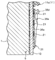
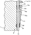
- FIG. 4 is a sectional view taken along line IV-IV shown in FIG. 2.
- FIG. 5 is a sectional view taken along line VV shown in FIG. 3.
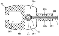
- FIG. 3 is a cross-sectional view taken along line VII-VII shown in FIG.
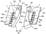
- FIG. 6 is a plan view showing the main parts of a right element member and a box member that can be used in place of the right element member and the box member of Examples 1 to 3. It is a perspective view of a box member. It is a top view which shows typically the principal part of the product (clothing) with a slide fastener which concerns on Example 4 of this invention. It is a perspective view which shows typically the butterfly stick part and box stick part of Example 4.
- FIG. 6 is a plan view showing the main parts of a right element member and a box member that can be used in place of the right element member and the box member of Examples 1 to 3.
- It is a perspective view of a box member. It is a top view which shows typically the principal part of the product (clothing) with a slide fastener which concerns on Example 4 of this invention. It is a perspective view which shows typically the butterfly stick part and box stick part of Example 4.
- FIG. 6 is a plan view showing the main parts of a right element member and a box member that can be used in
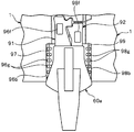
- Example 4 it is a top view which shows the positional relationship of the butterfly stick part of the state which meshed
- the product with a slide fastener is a garment with a slide fastener
- the product with a slide fastener according to the present invention is not limited to clothes (clothing), but shoes
- Various products such as daily miscellaneous goods such as foods and potatoes, products such as industrial materials, and various seats such as automobiles, trains, and airplanes are included.
- the opening and closing tool described in each of the following embodiments is provided with a butterfly pin portion on the left side when the garment that is the product is viewed from the front side, and a box portion or a box rod portion on the right side.
- the box part is arranged, and a person who wears the clothes is formed as a so-called right-and-left separating and inserting tool for operating the butterfly stick part with the right hand.
- the so-called left-side separation fitting is formed in a product with a slide fastener by reversing the positional relationship between the butterfly pin and the box in the left-right direction from the following embodiments. It is also possible.
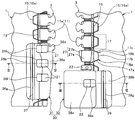
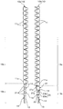
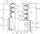
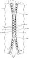
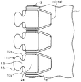
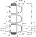
- FIG. 1 is a plan view schematically showing a main part of a garment with a slide fastener according to the first embodiment
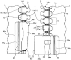
- FIG. 2 is a plan view showing a state in which the separation / insertion tool is separated from the main part of the garment. It is.
- FIG. 3 and FIG. 6 are side views of the placket part of the garment provided with the butterfly bar part and the box part of the separation / insertion tool as seen from the mating counterpart side.
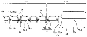
- FIG. 8 is a plan view showing the left and right element members.
- the front-rear direction refers to the length direction of the element member parallel to the sliding direction of the slider, and in particular, the direction in which the slider slides so as to mesh the left and right element rows is the front, The direction of sliding so as to separate the left and right element rows is the rear.
- the front and back can also be paraphrased as the direction which leaves
- the left-right direction refers to the width direction of the element member (or the width direction of the cloth serving as the fastener attaching member), for example, the direction orthogonal to the sliding direction of the slider and parallel to the front and back surfaces of the cloth. is there.
- the vertical direction means a direction perpendicular to the front-rear direction and the left-right direction, for example, the thickness direction of the element member orthogonal to the front and back surfaces of the fabric.
- the direction on the side where the slider handle is arranged with respect to the element member is defined as the upper side, and the direction on the opposite side as the lower direction.
- the product with the slide fastener according to the first embodiment is a garment (clothing) with a slide fastener, and the element member 10 is formed on the cloth 1 that forms the front body (particularly, the front part) serving as an opening / closing part in the garment.
- Left and right element mounting edges 2 to be mounted are arranged.
- the left and right element rows 3 are formed by sewing element members 10 on the left and right element mounting edges 2 of the garment.
- a separation fitting 30 having a butterfly pin portion 31 and a box portion 32 is attached to the rear end portions (lower end portions in the drawing of FIG. 1) of the left and right element attachment edge portions 2. Further, a single slider 60 is slidably attached to the left and right element rows 3 along the element row 3, and the slider 60 is slid forward or backward along the element row 3.
- the front part (opening / closing part) of the front body on the left and right sides of the clothes can be closed or opened by the engagement or separation of the left and right element rows 3.
- the fabric 1 (also referred to as garment fabric) constituting the front body of the garment is a fastener attaching member to which the element member 10 is attached.
- the slide fastener configured in the first embodiment includes a pair of left and right fastener stringers including an element row 3 formed by directly fixing the element member 10 to the cloth 1 of the clothes, and elements of the left and right fastener stringers. It has a slider 60 capable of meshing and separating the rows 3 and an opening / closing insert 30 arranged adjacent to the rear ends of the left and right element rows 3.
- Cloth 1 used as a fastener attaching member has performance and properties (softness, thickness, texture, color, etc.) necessary for clothes.
- the fabric 1 to which the element member 10 is sewn is cut into a predetermined shape and size according to the shape and design of clothes.
- the thickness of a general conventional fastener tape is 1.1 mm to 1.5 mm
- the fabric 1 that is a fastener attaching member used in Example 1 and other portions of the fabric are as follows. From the viewpoint of weight reduction, it is formed thin, and has a thickness of, for example, 0.2 mm to 1.0 mm, preferably 0.4 mm to 0.7 mm.
- the left and right element mounting edges 2 provided on the fabric (fastener attaching member) 1 are linearly arranged at positions facing each other on the front body of the garment (that is, facing edges of the placket). And it is arranged continuously. Further, as will be described later, in the first embodiment, the left and right member mounting portions 5 are formed by fixing the extending portions 13b of the fixing member 13 of the element member 10 to the left and right element mounting edges 2. These left and right member mounting portions 5 are also arranged at positions facing each other.
- the left and right element attachment edges 2 are formed by folding back side edges that are the cut ends of the fabric 1 into a U shape in the width direction of the element member 10. .
- the element attachment edge 2 is formed locally thicker than the other portions of the thin fabric 1 and the strength of the element attachment edge 2 is increased. it can. Thereby, it becomes difficult to cut
- the element member 10 and the release fitting 30 can be firmly fixed to the element mounting edge 2.
- the side edge of the fabric 1 is folded in a U-shape, so that, for example, even if the side edge of the fabric 1 is unraveled, the unraveling is hidden on the back side of the element mounting edge 2 and You can prevent it from appearing. Thereby, the clothes with a slide fastener can be provided with good appearance quality (appearance). Further, it is possible to prevent the meshing of the left and right element rows 3 from being deteriorated and the slidability of the slider 60 from being lowered due to the unraveling occurring at the side edge of the fabric 1.
- the configuration of the clothing fabric 1 is not particularly limited, and can be appropriately changed according to the usage of the clothing.
- the element member 10 includes a left element member 10 a (also referred to as a first element member) on which a butterfly pin portion 31 is provided and a box body portion (box portion) 32. And a right element member 10b (also referred to as a second element member).
- the left element member 10a and the right element member 10b are different in form at the rear end of the element member 10.
- the left and right element members 10a and 10b will be described in detail.
- the left element member 10a includes a plurality of independent fastener elements 11 (also referred to as single fastener elements), a single string-like fixing member 13 that connects the plurality of fastener elements 11 at a constant interval, and a fixing member 13 And three first anchor elements 21 arranged at the rear end portion (extended portion 13b described later).
- the right element member 10b includes a plurality of independent fastener elements 11, a single string-like fixing member 13 that connects the plurality of fastener elements 11 at a constant interval, and a rear end portion of the fixing member 13 ( There are two types of second anchor element 22 and third anchor element 23 arranged in the extending part 13b), and a box side insertion part 27 arranged in the rear end part.
- each fastener element 11 disposed on the left element member 10a and each fastener element 11 disposed on the right element member 10b are formed in a bilaterally symmetric shape, but are substantially the same. It has a structure.
- the plurality of fastener elements 11 arranged on the element members 10 a and 10 b are aligned in a line along the length direction of the element member 10 in a state where the fastener elements 11 are connected at equal intervals by the fixing member 13.
- These fastener elements 11 are formed integrally with the fixing member 13 by injection molding a thermoplastic resin such as polyamide, polyacetal, polypropylene, polybutylene terephthalate, etc. into one fixing member 13. 13 is formed so as to cover the entire outer periphery.
- the end on the side where the lengthwise separation / insertion tool 30 is disposed (in the case of the first embodiment).
- the material of the fastener element 11 is not limited to the above-described synthetic resin.
- the fastener element 11 can be formed of other synthetic resin or metal.
- the element member 10 of the first embodiment is not limited to the one in which the fastener element 11 is formed by injection molding a thermoplastic resin on the fixing member 13.
- the element member 10 is formed by injection molding a thermoplastic resin to a predetermined shape. The element formed in (1) is fixed to the fixing member 13 by welding or adhesion.
- the element member 10 in the present invention is not limited to the one in which the synthetic resin-made fastener element 11 made of an injection molding is integrally formed and connected to the fixing member 13 as in the first embodiment.
- the element member of the present invention includes, for example, an element member formed by performing metal die casting on a string-like fixing member 13 and a wire rod (so-called Y bar) having a substantially Y-shaped cross section. Further, the element is formed by attaching the element to the fixing member 13 by pressing deformation, and the element is formed by punching a thin plate member, and the element is further attached to the fixing member 13 by pressing deformation. Element members to be used.
- the fastener element 11 has a trunk portion 12 a fixed to the fixing member 13, and continuously extends in the width direction of the element member 10 from the trunk portion 12 a and has a length.
- a neck portion 12b having a constricted shape so that the dimension in the direction becomes narrower, a meshing head portion 12c extending continuously from the neck portion 12b in the width direction and having a substantially oval shape in plan view, and a front side from the neck portion 12b
- a protruding piece 12d also referred to as a shoulder protruding rearward.
- the trunk portion 12a of the fastener element 11 has a substantially rectangular parallelepiped shape with a constant thickness, and is formed so as to wrap around the fixing member 13 so that the fixing member 13 penetrates in the front-rear direction.
- An insertion recess 12e into which a part of the element attachment edge 2 of the fabric 1 is inserted is provided along the length direction of the element member 10 on the side surface portion of the body portion 12a facing the fabric 1. .
- the element member 10 is fixed to the element mounting edge 2 by the fixing sewing portion 15 in a state where the element mounting edge 2 of the fabric 1 is inserted into the insertion recess 12e, so that each fastener element 11 is in a predetermined direction. With this, the element mounting edge 2 can be firmly and stably fixed.
- the fixing member 13 has penetrated along the length direction in the state enclosed by the trunk
- a concave groove portion 12f is formed at the top end portion (tip portion) of the meshing head portion 12c along the length direction so as to fit the protruding piece portion 12d of the mating counterpart fastener element 11 when the left and right element rows 3 are meshed.
- the shape of the fastener element 11 is not particularly limited, and can be arbitrarily changed.
- the left and right fixing members 13 in the first embodiment are formed of the same string-like member that is flexible and has a substantially circular cross section perpendicular to the length direction.
- each fixing member 13 is preferably a member having a circular cross section and a constant cross-sectional area in the length direction.
- Such a fixing member 13 is formed, for example, by wrapping a monofilament, a twisted yarn (twisted string), or a core yarn composed of a plurality of aligned multifilaments in a bag weave knitted with a plurality of knitting yarns. It is possible to use a cord body (also referred to as a knit cord).
- the fixing member 13 used in the present invention is not particularly limited as long as a plurality of elements can be attached. Further, the cross-sectional shape of the fixing member 13 can be arbitrarily changed as necessary. Furthermore, the element member 10 of the present invention may be formed by connecting a plurality of elements by two or more string-like fixing members 13.
- the fixing member 13 has an element holding portion 13a to which a plurality of fastener elements 11 are attached at equal intervals in the longitudinal direction of the element member 10, and further to the rear than the end fastener element 11a described above. And an extending portion 13b that extends. In other words, the extending portion 13 b of the fixing member 13 continuously extends rearward from the element holding portion 13 a of the fixing member 13.
- the three first members used for positioning the butterfly pin member 36 are used.
- An anchor element 21 is arranged.
- arranged in the extension part 13b on the left side is formed as the exposed part 14 which the extension part 13b exposes.
- the overall length including the exposed portion 14 of the left extension 13b is larger than the size of the mounting pitch of the plurality of fastener elements 11 attached at equal intervals in the length direction, preferably It is set to be larger than twice the size of the mounting pitch.
- the attachment pitch (interval) of the fastener elements 11 is an interval in the length direction between predetermined positions (for example, center positions) in the length direction of the fastener elements 11 in the fastener elements 11 adjacent to each other in the length direction. Say (dimensions).
- the three first anchor elements 21 in the first embodiment are arranged in order from the end fastener element 11a described above at the same attachment interval as the attachment interval (attachment pitch) of the fastener elements 11 in the left element member 10a. ing. That is, in the left element member 10a, the plurality of fastener elements 11 and the three first anchor elements 21 are intermittently and regularly aligned with a certain interval along the length direction.
- the exposed portions 14 provided on the left extending portion 13b are also intermittently arranged at regular intervals along the length direction. By forming the exposed portion 14 in the extended portion 13b, a part of the exposed portion 14 is held by being held in a sewing thread of a fixing sewing portion 15 to be described later, thereby the left extended portion. 13 b is stably fixed to the element mounting edge 2 of the fabric 1.
- the left element member 10a is used with the staggered sewing machine with respect to the element mounting edge 2 of the fabric 1.
- the zigzag fixing sewing portion 15 is formed, the zigzag sewing sewing machine needle is not interfered with the fastener element 11 or the first anchor element 21, and the element holding portion 13a of the fixing member 13 is formed.
- the region of the extending portion 13b can be sewn and fixed to the element attachment edge portion 2 with the same stitch pattern.
- the number of the first anchor elements 21 to be installed is, for example, the length dimension of the extending portion 13b. It can change arbitrarily according to etc.
- the first anchor element 21 of the first embodiment bulges from the extending portion 13b of the fixing member 13 in the radial direction of the fixing member 13 and partially wraps the extending portion 13b of the fixing member 13 from the outside. It has a columnar shape.
- the first anchor element 21 has a cylindrical shape centering on the central axis along the length direction of the fixing member 13 whose cross section is circular or substantially circular.
- the transverse section refers to a section orthogonal to the length direction. For this reason, when the cross section of the first anchor element 21 is viewed, the first anchor element 21 bulges out from the fixing member 13 in a donut shape in the radial direction.
- the dimension of the first anchor element 21 that bulges in the radial direction is the same size on the entire circumference of the first anchor element 21.
- the first anchor element 21 of the first embodiment may have a spherical or hemispherical shape, or a shape obtained by combining at least two of a cylindrical shape, a spherical shape, or a hemispherical shape. . Since the first anchor element 21 has such a shape, even if the fixing member 13 is twisted, the shape (orientation) of the first anchor element 21 itself does not change. The positioning function of the butterfly pin member 36 and the effect of improving the attachment strength of the butterfly pin portion 31 by housing the first anchor element 21 in the butterfly rod portion 31 can be exhibited appropriately and stably. In the present invention, the first anchor element 21 may be formed in other shapes such as a prismatic shape or the shape of the body 12a of the fastener element 11 described above.
- the extending portion 13b of the fixing member 13 in the right element member 10b includes, as shown in FIG. 8, a rear second anchor element 22, a front third anchor element 23, a third anchor element 23, Box body side insertion portions 27 arranged between the end fastener elements 11a are respectively provided at predetermined positions.
- a portion where neither the second anchor element 22 nor the third anchor element 23 is arranged is formed as an exposed portion 14 on the right extending portion 13b, and a part of the exposed portion 14 is sewn for fixing.
- the right extending portion 13 b is stably fixed to the element mounting edge 2 of the fabric 1.
- the entire length including the exposed portion 14 of the right extension 13b is larger than the size of the mounting pitch between the two fastener elements 11 adjacent in the length direction, and preferably the size of the mounting pitch is large. It is set to be larger than twice.
- the second anchor element 22 and the third anchor element 23 of the first embodiment are used for positioning the box member 38 when the box member 38 is attached as a box member as will be described later.
- the box-side insertion portion 27 is accommodated in an element guide path (to be described later) of the slider 60 when the butterfly pin portion 31 is accommodated in the box body portion 32 and the left and right element rows 3 are engaged with each other.
- the positional relationship between the butterfly bar portion 31 and the box body portion 32 is stabilized by being inserted into a later-described butterfly rod side recess 36e.
- the predetermined positions in the second anchor element 22, the third anchor element 23, and the box side insertion portion 27 are the right element member 10b and the zigzag stitch sewing machine as in the case of the left element member 10a.
- the sewing needle is caused to interfere with the second anchor element 22, the third anchor element 23, and the box side insertion portion 27 when the zigzag fixing sewing portion 15 is attached to the element attachment edge 2 of the fabric 1.
- the position of the element holding portion 13a and the region of the extending portion 13b of the fixing member 13 can be sewn with the same stitch pattern.
- the 2nd anchor element 22 of the present Example 1 is distribute
- the second anchor element 22 has a columnar shape that bulges from the extending portion 13 b of the fixing member 13 in the radial direction of the fixing member 13 and wraps around the extending portion 13 b of the fixing member 13.
- the third anchor element 23 is arranged at a position between the second anchor element 22 and the box side insertion portion 27 in the length direction.
- the third anchor element 23 is integrally formed with a cylindrical portion 23a having a cylindrical shape that bulges in the radial direction of the fixing member 13 from the extending portion 13b of the fixing member 13, and the cylindrical portion 23a above the cylindrical portion 23a.
- a diameter-enlarged portion 23b having a truncated cone shape that bulges in the radial direction from the cylindrical portion 23a.
- the cylindrical portion of the third anchor element 23 is formed slightly thinner than the cylindrical second anchor element 22, and a part of the cylindrical portion of the third anchor element 23 is provided with a box body portion 32. Sometimes it is housed in the box body 32 (specifically, a box-side anchor housing recess 38f to be described later of the box body section 32) and cannot be seen from the outside.
- the second anchor element 22 and the third anchor element 23 of the first embodiment have a spherical or hemispherical shape, or a shape obtained by combining at least two of a cylindrical shape, a spherical shape, or a hemispherical shape. It may also have other shapes such as a prismatic shape, the shape of the body 12a of the fastener element 11 described above, and the overall shape of the fastener element 11 depending on circumstances.
- the box-side insertion portion 27 has a rectangular columnar fixing portion 27a fixed to the fixing member 13, and a thin plate-like insertion piece portion 27b protruding from the fixing portion 27a in the width direction of the element member 10.
- the insertion piece portion 27 b has a shape that exhibits a substantially trapezoidal shape in a plan view of the element member 10.
- the first anchor element 21 to the third anchor element 23 and the box side insertion portion 27 described above are formed by injection-molding the same thermoplastic resin as the fastener element 11 to each fixing member 13, It is integrally formed.
- the injection molding of the first anchor element 21 to the third anchor element 23 and the box side insertion portion 27 may be performed simultaneously with the injection molding of the fastener element 11 or may be performed separately from the injection molding of the fastener element 11. .
- the materials of the first anchor element 21 to the third anchor element 23 and the box side insertion portion 27 are not particularly limited, and these portions may be formed of a synthetic resin or metal different from the fastener element 11. .
- a molded body of the first anchor element 21 to the third anchor element 23 and the box side insertion portion 27 formed in advance by injection molding of a thermoplastic resin into a predetermined shape is welded or bonded to the fixing member 13. It is also possible to fix.
- the left side element member 10a and the right side element member 10b in the first embodiment as described above are arranged at positions adjacent to the outer sides in the width direction with respect to the element mounting edge portions 2 of the left and right fabrics 1, respectively.
- the fixing sewing part (fixing sewing line) 15 fixes the sewing machine.
- the fixing sewing portion 15 is formed by sewing a staggered sewing machine, and is formed by bending in a zigzag shape in the length direction by main sewing.
- the left and right element members 10 are fixed to the element mounting edge 2 in a state where at least the body 12 a of each fastener element 11 is in contact with the element mounting edge 2 of the fabric 1.
- the extending portion 13b of the fixing member 13 is fixed to the element mounting edge 2 in a state where at least the respective anchor elements 21, 22, and 23 are in contact with the element mounting edge 2 of the fabric 1.
- the staggered sewing machine is a sewing machine that can sew the fabric 1 and the like in a zigzag manner by swinging the sewing needle along the crossing direction that intersects the feed direction of the sewing machine.
- the swinging of the sewing needle in the staggered sewing machine is sometimes referred to as staggered swing.
- staggered swing While using such a staggered sewing machine, for example, set the coordinate data of the X coordinate (position in the feed direction) and the Y coordinate (position in the cross direction) as the needle drop position of the sewing needle to the staggered sewing machine.
- the sewing thread of the fixing sewing portion 15 formed by the main sewing is an upper thread that runs on the surface (first surface) of the element attachment edge portion 2 and contacts the surface side half of the fixing member 13.
- (Needle thread) 16 a and lower thread (bobbin thread) 16 b that travels on the back surface (second surface) of the element mounting edge 2 and contacts the back surface side half of the fixing member 13.
- the fixing sewing portion 15 is formed by the main sewing, the upper thread 16a and the lower thread 16b are arranged in a plane-symmetrical positional relationship.
- the upper thread 16a and the lower thread 16b of the main stitch are a piercing position where the fixing sewing portion 15 pierces the element mounting edge 2 (a first piercing position 18a and a second piercing position 18b described later). 3 and FIG. 6 and the position in contact with the outer peripheral surface of the fixing member 13 cross each other (entanglement).
- the upper thread 16a and the lower thread 16b of the sewing part 15 for fixing are an upper thread 16a that travels on the surface of the element mounting edge 2 and a lower thread 16b that travels on the back surface of the element mounting edge 2 in the thickness direction.
- the upper thread 16a and the lower thread 16b in the first embodiment intersect each other at the position of the central portion in the thickness direction of the element mounting edge 2.
- the crossing position of the upper thread 16a and the lower thread 16b in the thickness direction can be easily changed by controlling the tension of the upper thread 16a and the lower thread 16b in the staggered sewing machine.
- the fixing sewing portion 15 is formed by stitches of main stitches for racing the upper thread 16a and the lower thread 16b with other threads using the staggered sewing machine as described above. As a result, the fixing sewing portion 15 penetrates the element attachment edge portion 2 of the fabric 1 and the upper thread 16a and the lower thread 16b are brought into contact with the outer peripheral surface of the fixing member 13 of the element member 10 while the fixing member 13 is moved. Can be supported to wrap. Therefore, the element member 10 is easily and stably attached and fixed to the element attachment edge portion 2 of the fabric 1 by the fixing sewing portion 15.
- the upper thread 16a and the lower thread 16b of the fixing sewing portion 15 after sewing are made to the surface of the fastener element 11 with respect to the fastener element 11 ( It can prevent effectively that it arrange
- the fixing sewing portion 15 is configured so that the upper thread 16a and the lower thread 16b of the main sewing intersect the following on the outer peripheral surface of the fixing member 13 with respect to one fastener element 11 from the outer periphery intersecting position. It has a unit travel region 17 that travels to an outer periphery crossing position that intersects on the outer peripheral surface of the fixing member 13, and a seam of the unit travel region 17 is repeatedly arranged for each fastener element 11 in the length direction.
- the seam of each unit travel region 17 forming the fixing sewing portion 15 of the first embodiment has two piercing positions at which the fixing sewing portion 15 pierces the element attachment edge portion 2.
- the seam pattern in the unit travel region 17 is not limited to the region where the fastener element 11 of the element member 10 is disposed, but also the extended portion 13b of the fixing member 13 where the fastener element 11 is not disposed.
- the extension portion 13b of the fixing member 13 is fixed to the element attachment edge portion 2.
- the upper thread 16a and the lower thread 16b of the fixing sewing portion 15 in the first embodiment are fixed to the fixing member 13 in each unit traveling region 17.
- a first traveling portion 17a that is arranged from the outer circumferential intersection position where the upper thread 16a and the lower thread 16b intersect on the outer circumferential surface to the first first piercing position 18a, and the second second piercing from the first piercing position 18a. It has the 2nd driving
- the first traveling portion 17a is configured so that the upper thread 16a (or the lower thread 16b) extends in the width direction (or substantially in the width direction) from the above-described outer circumferential intersection position to the position in the width direction corresponding to the side surface portion of the fastener element 11.
- the first piercing position 18a is formed by traveling obliquely with respect to the width direction.
- the boundary portion between the portion traveling along the width direction of the first traveling portion 17a and the portion traveling obliquely with respect to the width direction may be in contact with the body portion 12a of the fastener element 11.
- the second traveling portion 17b is formed by the upper thread 16a (or the lower thread 16b) traveling along the length direction of the element member 10 between the first piercing position 18a and the second piercing position 18b. Is done.
- the third traveling portion 17c travels obliquely with respect to the width direction from the second piercing position 18b to the position in the width direction corresponding to the side surface portion of the fastener element 11, and the outer thread 16a (or the lower thread 16b) travels obliquely with respect to the width direction.
- the intersection is formed by traveling along the width direction (or substantially the width direction). In this case, the boundary between the portion that travels obliquely with respect to the width direction of the third traveling portion 17 c and the portion that travels along the width direction may be in contact with the body portion 12 a of the fastener element 11.
- the first piercing position 18a and the second piercing position 18b through which the fixing sewing portion 15 pierces the element mounting edge 2 of the fabric 1 are separated from the inner side surface portion of each fastener element 11 by a width. It is formed so as to be separated toward the inner side of the fabric 1 in the direction (in other words, the direction opposite to the direction facing the fastener element 11 on the engagement partner side). That is, in the width direction of the element member 10, a fixed interval is provided between the first and second piercing positions 18 a and 18 b of the fixing sewing portion 15 and the position of the side surface portion of each fastener element 11. ing.
- the positions of the first and second piercing positions 18a and 18b of the fixing sewing portion 15 By setting the positions of the first and second piercing positions 18a and 18b of the fixing sewing portion 15 in this way, the upper thread 16a and the lower thread 16b of the fixing sewing portion 15 are placed on the front and back surfaces of the fastener element 11. Overlap can be prevented more stably. Moreover, the space
- the dimension in the length direction of the unit traveling region 17 of the fixing sewing portion 15 is set to the same size in the region of the element holding portion 13a and the region of the extending portion 13b in the fixing member 13. ing.
- the unit of the fixing sewing portion 15 is fixed between the region of the element holding portion 13a and the extension portion 13b of the fixing member 13. It is also possible to vary the lengthwise dimension in the travel region 17.
- the lengthwise dimension can be varied for each unit travel region 17 of the fixing sewing portion 15.
- the position of the side surface portion of each fastener element 11 in the width direction and the piercing position of the fixing sewing portion 15 (first piercing position 18a and second piercing position 18b).
- a supplementary sewing portion 19 for continuously tightening the upper thread 16a and the lower thread 16b of the fixing sewing portion 15 so as not to loosen is formed in a region between them.
- the auxiliary sewing portion 19 has a length of the element member 10 by stitches of the main sewing that performs the other thread racing of the auxiliary upper thread (needle thread) and the auxiliary lower thread (bobbin thread) using a sewing machine. It is formed linearly along the vertical direction.
- the auxiliary sewing portion 19 By forming the auxiliary sewing portion 19 by the main stitch in this manner, the auxiliary sewing portion 19 can be easily and stably formed, and the upper thread 16a and the lower thread 16b of the fixing sewing portion 15 can be stably pressed. (Tighten).
- the auxiliary upper thread and the auxiliary lower thread of the auxiliary sewing portion 19 are the piercing position where the auxiliary sewing portion 19 pierces the element mounting edge 2 and the thickness direction at the element mounting edge 2 Are crossed (entangled) with each other at the position of the central portion.
- the crossing position of the auxiliary upper thread and the auxiliary lower thread in the thickness direction can be changed by controlling the tension of the auxiliary upper thread and the auxiliary lower thread in the sewing machine.
- the auxiliary upper thread and the auxiliary lower thread are fixed to the fixing sewing portion in the region overlapping the first traveling portion 17a and the third traveling portion 17c in the fixing sewing portion 15. 15 on the upper thread 16a and the lower thread 16b.
- the upper thread 16 a and the lower thread 16 b of the fixing sewing portion 15 are directed to the element mounting edge 2 from above and below with the auxiliary upper thread and the auxiliary lower thread. It can be pressed down (in other words, toward the inside in the thickness direction). Thereby, the upper sewing thread 16a and the lower sewing thread 16b can be tightened by the auxiliary sewing section 19 to apply tension. For this reason, even if slack has arisen in the upper thread 16a and the lower thread 16b of the sewing part 15 for fixation, the slack can be eliminated. Further, it is possible to effectively prevent the upper thread 16a and the lower thread 16b of the fixing sewing portion 15 from being loosened.
- the auxiliary sewing portion 19 is formed by linear main sewing along the length direction.
- the auxiliary sewing portion 19 includes the upper thread 16a of the fixing sewing portion 15 and the upper thread 16a. If the lower thread 16b can be pressed toward the element attachment edge 2, the auxiliary sewing portion 19 can be formed by stitches other than the main stitch such as double chain stitch.
- the left and right fabric 1 are formed along the element mounting edge 2.
- extension portion 13b of the fixing member 13 in the left element member 10a is fixed to the element attachment edge portion 2 of the left fabric 1 by the fixing sewing portion 15 and the auxiliary sewing portion 19, whereby the left fabric 1 A member mounting portion that is formed on the rear side edge portion by the extending portion 13b of the fixing member 13 and a part of the element mounting edge portion 2, and to which the butterfly pin member 36 of the separation fitting 30 is mounted. 5 is formed.
- the fixing portion 15 b and the auxiliary sewing portion 19 fix the extending portion 13 b of the fixing member 13 of the right element member 10 b to the element attachment edge 2 of the right fabric 1, thereby allowing the right fabric 1
- a box member 38 is attached to the rear side edge portion by the extended portion 13 b of the fixing member 13 and a part of the element attachment edge portion 2 as a box member of the separation fitting 30.
- a member mounting portion 5 is formed.
- the split fitting tool 30 of the first embodiment includes a butterfly bar portion 31 provided on the member attachment portion 5 of the left-side fabric 1, a box portion 32 provided on the member attachment portion 5 of the right-side fabric 1, and the above-described components.
- Box-side insertion portion 27 In the present invention, instead of the box part 32 and the box side insertion part 27, it is also possible to form a box part with a box stick in which the box stick part is integrally formed in the box part as described later. It is.
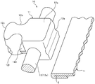
- the butterfly stick portion 31 of the first embodiment is obtained by attaching a butterfly stick member 36 made of synthetic resin such as nylon to the above-described member attaching portion 5 formed at the lower end portion of the left-side fabric 1 and the opposite side edge portion. Formed by.
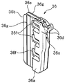
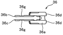
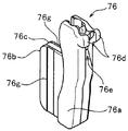
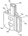
- the butterfly pin member 36 of the first embodiment is one of the constituent parts that form the separation / insertion tool 30. As shown in FIGS. 10 to 12, the wing pin member 36 includes a wing pin main body portion 36a that wraps a part of the extending portion 13b of the fixing member 13 along the fixing member 13, and a wing pin main body portion 36a side.
- the second butterfly fin portion 36c disposed on the lower surface (second surface) of the element mounting edge 2 and the front end portion of the butterfly rod main body portion 36a are integrally provided, and the end portion of the right element member 10b. It has a meshing part 36d that meshes with the fastener element 11a.
- the butterfly pin main body portion 36 a is provided with an accommodation holding portion (internal space portion) that accommodates and wraps a part of the member attachment portion 5 formed on the fabric 1.
- a cross section orthogonal to the length direction has a substantially U-shape.
- the butterfly body insertion portion 27 of the right element member 10b is inserted and accommodated in the opposite side surface portion of the butterfly rod body portion 36a facing the box body portion 32.
- a rod-side recess 36e is formed along the length direction.
- three upper surface side anchor accommodation holes 36f for accommodating the first anchor elements 21 are provided in the length direction at the connecting portion where the wing pin main body portion 36a and the upper surface side first wing pin fin portion 36b are connected. It is regularly provided with a predetermined interval.
- three lower surface side anchor receiving hole portions 36f for storing the first anchor elements 21 are also provided at the connecting portion where the bar main body portion and the second butterfly stick fin portion 36c on the lower surface side are connected as shown in FIG. Are provided in the same manner as the upper surface side anchor accommodating hole 36f.
- the fixing sewing part, the auxiliary sewing part, and the butterfly pole side sewing part The illustration of each sewing part such as is omitted.
- the upper surface side and the lower surface side anchor accommodating hole 36f are arranged at positions corresponding to each other and have a width dimension larger than the width dimension (dimension in the width direction) of the first anchor element 21.
- the butterfly rod member 36 is used.
- the upper surface of the first butterfly fin portion 36b and the lower surface of the second butterfly fin portion 36c of the butterfly rod member 36 accommodate a butterfly rod side sewing portion 37, which will be described later, formed when the butterfly rod member 36 is fixed.
- An accommodation concave groove portion 36g is provided along the length direction.
- the receiving groove portion 36g of the first butterfly fin portion 36b and the receiving groove portion 36g of the second butterfly fin portion 36c are formed at the same corresponding positions of the butterfly rod member 36 in the width direction. .
- a butterfly pin member in which the second butterfly fin portion 36c described above is excluded from 36 can also be used.
- the butterfly pin member 36 of the first embodiment When the butterfly pin member 36 of the first embodiment is attached to the member attachment portion 5 formed on the left-side fabric 1, first, the butterfly pin member 36 is connected to the first butterfly fin portion 36b and the second butterfly fin portion 36c.
- the member mounting portion 5 of the fabric 1 is elastically deformed so that the gap is slightly opened so that the member mounting portion 5 is inserted between the first butterfly fin portion 36b and the second butterfly fin portion 36c. Put on.
- the extending portion 13b of the fixing member 13 is inserted and accommodated in the above-described accommodation holding portion of the butterfly rod main body portion 36a, and the butterfly rod main body portion 36a is fixed to the fixing member. 13 wraps at least part of the outer periphery of the extending portion 13b. Further, the three first anchor elements 21 provided in the extending portion 13b of the fixing member 13 are connected to the three upper surface side anchor receiving hole portions 36f formed on the first butterfly pin fin portion 36b side of the butterfly rod member 36, and Then, it is inserted and accommodated in three lower surface side anchor accommodation holes 36f formed on the second butterfly fin portion 36c side.
- the butterfly pin member 36 can be easily and stably positioned at a predetermined position with respect to the member mounting portion 5 of the fabric 1, and the position of the butterfly pin member 36 can be prevented from shifting in the length direction and the width direction.
- the butterfly pin member 36 can be temporarily fixed temporarily at that position.
- the upper and lower anchor receiving holes 36f of the butterfly pin member 36 open to the outer surface of the butterfly pin member 36, and the first anchor element is interposed via the upper and lower anchor receiving holes 36f.
- the position 21 can be visually confirmed. For this reason, the said positioning of the butterfly stick member 36 can be performed easily and rapidly.
- a butterfly pin side sewing portion 37 is formed,
- the first butterfly pin fin portion 36b and the second butterfly rod fin portion 36c of the butterfly pin member 36 are sewn and fixed to the member mounting portion 5 of the fabric 1 by the butterfly pin side sewing portion 37.
- the butterfly bar side sewing portion 37 is formed linearly along the length direction of the element member 10 by stitches of main stitches that perform upper thread (needle thread) and lower thread (bobbin thread) racing with other threads. In this case, it is preferable that the butterfly bar side sewing portion 37 is formed by performing reverse stitching, thereby making it difficult to cause the end of the butterfly rod side sewing portion 37 to be unraveled.
- the sewing needle is inserted into the receiving groove portion 36g of the first butterfly fin portion 36b and the receiving groove portion 36g of the second butterfly fin portion 36c.
- the butterfly pin side sewn portion 37 can be formed in the accommodating groove portion 36g of the first butterfly rod fin portion 36b and the accommodating groove portion 36g of the second butterfly rod fin portion 36c. Since the butterfly pin member 36 is thinly formed in the accommodating groove portion 36g of the first butterfly fin portion 36b and the accommodating groove portion 36g of the second butterfly fin portion 36c, a sewing needle is inserted into the butterfly rod member 36.
- the butterfly pin side sewn portion 37 is accommodated in the accommodating recess groove portion 36g of the first butterfly pin fin portion 36b and the accommodating recess groove portion 36g of the second butterfly rod fin portion 36c. It is possible to make it difficult to make the upper and lower flange portions, which will be described later, of the slider 60 come into contact with each other, thereby making it difficult to cause thread breakage in the butterfly pin side sewing portion 37.
- the butterfly pin side sewing portion 37 is formed by the sewing machine, and the member mounting portion 5 and the butterfly pin member 36 of the fabric 1 are sewn together, so that the butterfly rod member 36 of the member mounting portion 5 of the fabric 1 is sewn.
- the butterfly pin 31 formed from the butterfly pin member 36 is fixed to a predetermined position, and the end element 11a of the left element row 3 is attached to the fabric 1 to which the left element member 10a is attached. Adjacent and can be appropriately provided so as to continue from the left element row 3 along the length direction.
- the attachment strength of the butterfly stick part 31 to the fabric 1 is increased, It is possible to make it difficult for the butterfly stick 31 to fall off the fabric 1.
- the butterfly rod body portion 36a is disposed in an element guide path (described later) of the slider 60 when the butterfly pin member 36 is fixed to the member mounting portion 5. It is formed to have a height dimension that can be inserted into the. Particularly in the case of the first embodiment, the maximum value of the height dimension of the butterfly pin main body 36 a is set to the same size as the height dimension of the fastener element 11. In the present invention, it is preferable that the height dimension of the butterfly pin main body 36a is the same as the height dimension of the fastener element 11, but a range of ⁇ 20% relative to the height dimension of the fastener element 11 is used. It only has to be set within.
- first butterfly rod fin portion 36b on the upper surface side and the second butterfly rod fin portion 36c on the lower surface side are provided on the butterfly rod portion 31 of the first embodiment.
- first butterfly fin portion 36b and the second butterfly fin portion 36c are sewn to the member attaching portion 5 of the cloth 1, the member attaching portion 5 is protected and the member attaching portion 5 itself is hardly unraveled. can do.
- first butterfly fin portion 36b and second butterfly fin portion 36c the rigidity of the opposite edge portion on the rear end side of the fabric 1 is enhanced by the sewn first butterfly fin portion 36b and second butterfly fin portion 36c.
- the upper surface of the first butterfly fin portion 36b and the lower surface of the second butterfly fin portion 36c are arranged at a height position closer to the fabric 1 through a step than the upper and lower surfaces of the butterfly rod main body portion 36a. Yes.
- the height dimension from the upper surface of the first butterfly fin portion 36 b to the lower surface of the second butterfly fin portion 36 c in the butterfly rod portion 31 can be inserted into the insertion gap formed between the upper and lower flanges of the slider 60.
- the size is set.
- the length dimension (dimension in the length direction) and the width dimension (dimension in the width direction) in the first butterfly fin part 36b and the second butterfly fin part 36c are not limited and can be arbitrarily changed. is there.
- a box member 38 made of synthetic resin such as nylon is attached to the above-described member attaching part 5 formed at the rear end part of the right fabric 1 and the opposite side edge part. Formed by.
- the box member 38 of the first embodiment is another component part that forms the separation / insertion tool 30.
- the box member 38 includes a box body portion (box body portion) 38 a that wraps the extending portion 13 b of the fixing member 13 along the fixing member 13.
- a first box fin 38b extending along the width direction from the side edge of the box body 38a toward the inside of the fabric 1 and disposed on the upper surface (first surface) of the element mounting edge 2;
- a second box fin 38c extending along the width direction from the side edge of the box body 38a toward the inside of the fabric 1 and disposed on the lower surface (second surface) of the element mounting edge 2;
- the box body 38a of the first embodiment has a substantially rectangular parallelepiped or cubic outer shape.
- a butterfly pin housing portion 38d into which the butterfly rod body portion 36a of the butterfly rod portion 31 is inserted and housed is the front end of the box body body portion 38a. It is provided from the edge toward the rear.
- an accommodation holding portion (space portion) that houses and wraps a part of the member mounting portion 5 formed on the fabric 1, and a second part.
- a box-side anchor accommodating hole 38e for accommodating the anchor element 22 and a box-side anchor accommodating recess 38f for accommodating a part of the third anchor element 23 are provided on the upper surface side and the lower surface side of the box body main body 38a. Is provided.
- the box side anchor receiving hole 38e is formed to have a width dimension larger than the width dimension of the second anchor element 22. In this manner, by increasing the width dimension of the box-side anchor receiving hole 38e, the box member 38 is attached in the attachment of the box member 38 to the member attachment portion 5 of the fabric 1 as in the case of the butterfly pin member 36. Since the box side anchor receiving hole 38e can be hardly caught by the second anchor element 22, the box body member 38 can be attached smoothly.
- a box side sewing portion (box side sewing portion) 39 to be described later is provided on the upper surface of the first box fin portion 38 b and the lower surface of the second box fin portion 38 c in the box member 38, as in the case of the butterfly pin member 36.
- a housing groove 38g for housing the housing is provided along the length direction.
- the box member 38 is formed.
- a box member from which the second box fin portion 38c described above is excluded can also be used.
- the box member 38 of the first embodiment When attaching the box member 38 of the first embodiment to the member attachment portion 5 formed on the right side fabric 1, first, the box member 38 is spaced from the first box fin portion 38b and the second box fin portion 38c. Is elastically deformed so as to be slightly opened, and the member attaching portion 5 is sandwiched between the first box fin portion 38b and the second box fin portion 38c, so that the box member 38 is attached to the member attaching portion 5 of the cloth 1. Put on.
- the second anchor element 22 and a part of the third anchor element 23 provided in the extending portion 13b of the fixing member 13 are accommodated in the box side anchor receiving hole 38e and the box side anchor receiving portion of the box member 38.
- the recesses 38f are inserted and accommodated. Accordingly, the box member 38 can be stably positioned at a predetermined position with respect to the member mounting portion 5 of the cloth 1, and the position of the box member 38 can be prevented from shifting in the length direction and the width direction.
- the body member 38 can be temporarily fixed temporarily at that position.
- the box body side sewing portion 39 is connected to the above-described butterfly pin side. It is formed in the same manner as in the case of the sewing portion 37, and the first box fin portion 38 b and the second box fin portion 38 c of the box member 38 are sewn to the box side sewing portion 39 by the box side sewing portion 39. To be fixed. At this time, by forming the box side sewn portion 39 in the housing concave groove portion 36g of the first box fin portion 38b and the housing concave groove portion 36g of the second box fin portion 38c, similarly to the case of the butterfly pin member 36. It is possible to prevent the box member 38 from being damaged and to make it difficult to cause thread breakage in box side sewing.
- the box body member 38 is fixed to a predetermined position of the member mounting portion 5 of the fabric 1 by the box body side sewing section 39, whereby the box body section 32 formed from the box body member 38 is moved to the right side.
- the element member 10b can be appropriately provided on the fabric 1 to which the element member 10b is attached. In this case, since the second anchor element 22 and part of the third anchor element 23 of the right element member 10b are accommodated in the box body portion 32, the attachment strength of the box body portion 32 increases, and the box body portion 32 can be made difficult to fall off the fabric 1.
- the first box fin part 38b and the second box fin part 38c are sewn, so that the rear end side of the fabric 1 is sewn. It is possible to protect the opposite side edge and to prevent the fabric 1 from being unraveled.
- the height dimension from the upper surface of the first box fin portion 38 b to the lower surface of the second box fin portion 38 c in the box body portion 32 is set to a size that can be inserted into the insertion gap formed between the upper and lower flanges of the slider 60.
- the length dimension and width dimension in the 1st box fin part 38b and the 2nd box fin part 38c are not limited, It is possible to change arbitrarily.
- the slider 60 of the first embodiment has a slider body 61 and a handle 66 as schematically shown in FIG. Since the slider body 61 of the first embodiment is formed in substantially the same manner as a conventional general slider body, the detailed structure thereof is omitted, but the slider body 61 includes an upper blade 62 and A lower wing plate spaced from and parallel to the upper wing plate 62, a connecting column connecting the upper wing plate 62 and the front end portion (shoulder side end portion) of the lower wing plate, an upper wing plate 62 and a lower wing plate It has upper and lower flange portions arranged on the left and right side edge portions of the wing plate, and a handle attachment portion 63 arranged on the upper surface of the upper wing plate 62.
- left and right shoulder openings are formed at the front end portion of the slider body 61 with a guide column interposed therebetween, and a rear opening is formed at the rear end portion of the slider body 61.
- a substantially Y-shaped element guide path is formed between the upper wing plate 62 and the lower wing plate to communicate the left and right shoulder openings with the rear opening.
- an insertion gap is formed through which the element mounting edge portion 2 of the fabric 1 is inserted.
- the manufacturing method of the clothes with a slide fastener of the present Example 1 which has the above-mentioned separation fitting 30 is demonstrated.
- the cloth 1 for clothing, the left and right element members 10, and the butterfly bar member 36 and the box member 38 that form the separation / insertion tool 30 are prepared.
- a plurality of fastener elements 11 having a predetermined shape are formed by directly injection-molding synthetic resin into the element holding portion 13a of one string-like fixing member 13. Are formed at equal intervals.
- synthetic resin is directly injection-molded with respect to the extension part 13b of the same fixing member 13, and the three 1st anchor elements 21 are formed in a predetermined position.
- the synthetic resin is directly injection-molded into the element holding portion 13a of the other fixing member 13, and the plurality of fastener elements 11, the second anchor element 22, the third anchor element 23, and the box body
- the side insertion portions 27 are respectively formed at predetermined positions.
- the garment fabric 1 serving as a fastener attaching member is produced by knitting or weaving, and the butterfly bar member 36 and the box member having the predetermined shape as described above. 38 is formed by injection molding of synthetic resin.
- the element attachment edge part 2 is formed by folding back the side edge part used as the cutting edge part in the cut
- the element attachment edge portions 2 respectively formed on the pair of left and right front body fabrics 1 are provided at positions where they are arranged to face each other when the garment is manufactured.
- a sewing process for fixing the element member 10 to the element mounting edge 2 of the fabric 1 is performed using a staggered sewing machine.
- the element holding portion 13a and the extension member in the length direction of the fixing member 13 with respect to the element attachment edge 2 of the element member 10 and the cloth 1 are extended. Sewing by main sewing is performed so that the entire protruding portion 13b is bent in a zigzag shape.
- the element member 10 can be attached (sewn) to the element attachment edge 2 of the fabric 1 while the fixing sewing portion 15 is formed.
- the extending portion 13b of the fixing member 13 is sewn to the element mounting edge 2 of the fabric 1 by the fixing sewing portion 15, so that the butterfly pin member is formed on the opposite side edge at the rear end portion of the left and right fabrics 1.
- Member attachment portions 5 for attaching 36 and the box member 38 are formed.
- an auxiliary sewing portion 19 is formed by using a single-needle lockstitch machine for the element attachment edge portion 2 of the fabric 1 to which the element member 10 is fixed by the fixing sewing portion 15. Perform sewing processing.
- the auxiliary sewing part 19 which consists of the above-mentioned linear main sewing can be stably formed in the predetermined position of the element attachment edge part 2 in which the fixing sewing part 15 is formed. Since the upper thread 16a and the lower thread 16b of the fixing sewing portion 15 are pressed toward the element mounting edge 2 by the auxiliary sewing portion 19, the element member 10 is more firmly fixed to the element mounting edge 2. Can do.
- the butterfly pin member 36 and the box member 38 are attached to the member attachment portions 5 formed at the rear ends of the left and right fabrics 1 as described above. That is, when attaching the butterfly pin member 36, first, the butterfly pin member 36 is elastically deformed so that the distance between the first butterfly fin portion 36b and the second butterfly fin portion 36c is slightly opened, and the member of the fabric 1 The butterfly pin member 36 is put on the upper surface (first surface) and the lower surface (second surface) of the mounting portion 5. At this time, the three first anchor elements 21 provided in the extending portion 13b of the fixing member 13 are inserted into the three upper surface side anchor accommodating hole portions 36f and the lower surface side anchor accommodating hole portion 36f provided in the butterfly pin member 36. The butterfly pin member 36 can be stably positioned at a predetermined position.
- the butterfly pin member 36 (specifically, the butterfly pin side sewing portion 37 is formed in the housing concave groove portion 36g of the first butterfly fin portion 36b and the second butterfly fin portion 36c of the butterfly rod member 36.
- the first butterfly fin portion 36b and the second butterfly fin portion 36c can be sewn to the member mounting portion 5 of the fabric 1 and firmly fixed.
- the butterfly bar portion 31 of the separation / insertion tool 30 is provided so as to be continuous with the left element row 3.
- the box body member 38 When attaching the box member 38, basically the same operation as that of the butterfly pin member 36 is performed. Thereby, the box body member 38 can be sewn to the member mounting portion 5 of the cloth 1 and firmly fixed while the box body side sewing portion 39 is formed in the housing concave groove portion 36 g of the box body member 38. As a result, the box part 32 of the separation fitting 30 is provided behind the right element row 3.
- left and right clothes constituting parts in which the left and right element members 10a and 10b, the butterfly pin member 36, and the box member 38 are attached to the element attaching edge 2 are produced.
- left and right sleeve parts and clothes constituting parts (not shown) constituting the back body are prepared and prepared.
- garment is assembled by joining the garment component parts of each part produced by sewing or the like. Further, the slider 60 is slidably attached to the element row 3 formed on the element attachment edge 2 of the cloth 1, and a stopper (not shown) that prevents the slider 60 from dropping off at the front end portions of the left and right element rows 3 Is provided. As a result, a garment with a slide fastener including the separation / insertion tool 30 as shown in FIG. 1 is stably manufactured.
- a part of the cloth 1 of the garment not only constitutes the garment but also functions as a fastener tape for a conventional slide fastener.
- this garment with a slide fastener can have the function of a slide fastener in a form in which the presence of the fastener tape, which is an essential component in the conventional slide fastener, is omitted.
- the manufacturing cost (especially material cost) of clothes with a slide fastener can be reduced.
- the weight of the garment with the slide fastener can be reduced, and the flexibility of the garment can be improved.
- a separation / insertion tool 30 is formed at the rear end of the slide fastener, and this separation / insertion tool 30 can be operated in the same manner as a conventional general separation / insertion tool.
- this separation / insertion tool 30 can be operated in the same manner as a conventional general separation / insertion tool.
- the slider 60 is slid forward (in the closing direction), The left and right element rows 3 can be smoothly meshed.
- the fabric member 1 is provided with a desired function such as waterproofness and water repellency, and then the element member 10, the butterfly pin member 36 and the box member 38 are added to the fabric 1. Direct mounting is possible. For this reason, it is also possible to easily manufacture a high quality garment with a slide fastener having waterproofness and water repellency.
- FIG. 15 is a plan view showing a state where the separation / insertion tool is separated from the garment with a slide fastener according to the second embodiment.
- FIG. 16 is a cross-sectional view showing a cross section perpendicular to the vertical direction of the element member and the butterfly pin.
- FIG. 17 is an explanatory diagram schematically illustrating the movement when positioning the butterfly pin member of the second embodiment on the member mounting portion.
- FIG.18 and FIG.19 is the perspective view and front view which show a butterfly stick member.
- the garment with a slide fastener according to the second embodiment is not the first anchor element 21 according to the first embodiment, but the later-described fourth anchor element 24 and fifth anchor element 25 as anchor elements provided on the left element member 10c. Is different from the garment with the slide fastener of the first embodiment described above in that the wing rod portion 71 (the wing rod member 76) has a different shape.
- the garment with the slide fastener of Example 1 is formed in substantially the same manner.
- the left element member 10c used in the second embodiment includes a plurality of independent fastener elements 11, a single string-like fixing member 13 that connects the plurality of fastener elements 11 at a constant interval, and a fixing member 13.
- the fourth anchor element 24 and the fifth anchor element 25 are disposed in the extending portion 13b. Further, in the left extending portion 13b, a portion where the fourth anchor element 24 and the fifth anchor element 25 are not arranged is formed as the exposed portion 14.
- the overall length dimension of the left extending portion 13b including the exposed portion 14 is larger than the size of the mounting pitch between the two fastener elements 11 adjacent in the length direction, and preferably the mounting pitch is large. It is set to be larger than twice.
- the fourth anchor element 24 of the second embodiment is arranged at the rear end portion of the fixing member in the left element member 10c, and the fifth anchor element 25 is adjacent to the end fastener element 11a in the left element member 10c. It is arranged at the position to do. In this case, the interval between the fifth anchor element 25 and the end fastener element 11a is the same as the attachment interval of the fastener element 11 in the left element member 10c. Accordingly, when the left element member 10c is attached to the element attachment edge 2 of the fabric 1 with the zigzag fixing sewing portion 15 by using the zigzag sewing machine, the sewing needle does not interfere with the fifth anchor element 25.
- the region of the extending portion 13b of the fixing member 13 can be sewn with the same stitch pattern as the region of the element holding portion 13a.
- the extension portion 13b of the fixing member 13 is located on the rear side of the end fastener element 11a in the left fabric 1 and on the opposite side edge facing the box portion 32, and the element mounting edge 2 of the fabric 1
- the member attaching part 5 fixed to the is formed.
- the fourth anchor element 24 has a spherical shape that bulges from the extending portion 13b of the fixing member 13 in the radial direction of the fixing member 13.
- the fifth anchor element 25 has a columnar shape that bulges from the extending portion 13 b of the fixing member 13 in the radial direction of the fixing member 13.
- the butterfly stick member 76 of the second embodiment includes a butterfly stick body 76 a that wraps a part of the extending portion 13 b of the fixed member 13 along the fixed member 13, and a butterfly stick main body. Extending in the width direction from the side edge portion of the portion 76a, extending in the width direction from the first butterfly fin portion 76b disposed on the upper surface of the element mounting edge portion 2, and the side edge portion of the butterfly rod body portion 76a, The second butterfly fin portion 76c disposed on the lower surface of the element mounting edge 2 and the front end portion of the butterfly rod body portion 76a are integrally provided and meshed with the end fastener element 11a of the right element member 10b. And a meshing portion 76d.
- the first butterfly fin portion 76b, the second butterfly fin portion 76c, and the meshing portion 76d of the butterfly rod member 76 are substantially the same as the corresponding portions of the butterfly rod member 36 of the first embodiment. It is formed similarly.
- the wing stick side that receives the box side insertion portion 27 provided in the right element member 10b is disposed on the opposite side face portion of the wing stick body portion 76a facing the box body portion 32.
- a recess 76e is formed along the length direction.
- a part of the fourth anchor element 24 is accommodated and held on the inner peripheral surface of the rear end portion of the butterfly pin main body portion 76a of the second embodiment, and the fourth anchor element 24 is held.
- a rear end side anchor receiving recess 76f to be brought into sliding contact is provided.
- a front end side anchor accommodating recess 76h that accommodates and holds the fifth anchor element 25 is provided on the inner peripheral surface of the front end portion of the butterfly pin main body portion 76a of the second embodiment.
- the butterfly pin member 76 When the butterfly pin member 76 according to the second embodiment as described above is attached to the member attaching portion 5 formed on the left-side fabric 1, as shown in FIG.
- the member mounting portion 5 is obliquely sandwiched between the first butterfly fin portion 76b and the second butterfly fin portion 76c by being elastically deformed so that the gap between the portion 76b and the second butterfly fin portion 76c is slightly opened.
- the first butterfly fin portion 76b and the second butterfly fin portion 76c are placed on the member mounting portion 5 of the fabric 1.
- a part of the fourth anchor element 24 of the element member 10 is accommodated in the rear end side anchor accommodating recess 76f of the butterfly stick main body portion 76a.
- the butterfly pin main body 76 a is rotated counterclockwise in a plan view while being in sliding contact with the fourth anchor element 24 of the element member 10. Accordingly, the extension portion 13b of the fixing member 13 is accommodated and held in the butterfly rod main body portion 76a while the butterfly rod member 76 is placed on the member mounting portion 5 of the fabric 1, and the fifth anchor element of the element member 10 is also retained. 25 is inserted and accommodated in the front end side anchor accommodating recess 76h of the butterfly stick main body portion 76a. As a result, the butterfly pin member 76 can be stably positioned at a predetermined position with respect to the member mounting portion 5 of the fabric 1, and the butterfly pin member 76 can be temporarily temporarily fixed at that position.
- the member mounting portion 5 of the fabric 1 and the butterfly pin member 76 temporarily fixed to the member mounting portion 5 are stitched by lock stitching using a sewing machine in the same manner as in the first embodiment. Sew together.
- the butterfly pin side sewing portion 77 shown in FIG. 15 is formed, and the butterfly pin side sewing portion 77 is sewn and fixed to the member mounting portion 5 of the fabric 1.
- the butterfly pin side sewn portion 77 is formed in the accommodating concave groove portion 76g of the first butterfly pin fin portion 76b and the accommodating concave groove portion 76g of the second butterfly rod fin portion 76c.
- the butterfly bar portion 71 formed from the butterfly bar member 76 can be appropriately provided on the member mounting portion 5 of the fabric 1 so as to continue rearward from the left element row 3.
- the butterfly rod body portion 76 a is inserted into the element guide path of the slider 60 in a state where the butterfly pin member 76 is fixed to the member mounting portion 5. It is formed to have a possible height dimension.
- the right element member 10b and the box portion 32 are formed in the same manner as in the first embodiment.
- the garment with a slide fastener according to the second embodiment having the butterfly bar portion 71 as described above is formed without a fastener tape, and the detachable fitting 70 is formed by the butterfly bar portion 71 and the box body portion 32. Is formed. For this reason, also in the clothes with slide fasteners of the second embodiment, the same effects as the clothes with slide fasteners of the first embodiment can be obtained.
- FIG. 20 is a plan view showing a state where the separation / insertion tool is separated from the garment with a slide fastener according to the third embodiment.
- FIG. 21 is a plan view showing a state before the butterfly pin member of the third embodiment is attached to the member mounting portion.
- the anchor element is not arranged on the left element member 10d, and the front protrusion 86f that contacts the end fastener element 11a is provided on the butterfly stick 81 (wing stick member 86). ing.
- the left element member 10d used in the third embodiment includes a plurality of independent fastener elements 11 and a plurality of fastener elements 11 connected at a predetermined interval.
- the extending portion 13 b of the fixing member 13 there is a string-like fixing member 13
- no extension is provided on the extending portion 13 b of the fixing member 13
- the extending portion of the fixing member 13 is located behind the end fastener element 11 a. Only 13b extends. That is, in the third embodiment, the entire extending portion 13b is formed as the exposed portion 14.
- the rear side of the end fastener element 11a is fixed.
- the extending portion 13b of the member 13 is fixed to the element attachment edge 2 of the fabric 1 by the fixing sewing portion 15, whereby the box portion 32 is provided behind the end fastener element 11a in the left fabric 1 and on the rear side.
- the member attaching part 5 is formed in the opposing side edge part which opposes.
- the butterfly pin member 86 of the third embodiment includes a butterfly rod body portion 86a that wraps a part of the extending portion 13b of the fixing member 13 along the fixing member 13, and a width direction from the side edge portion of the butterfly rod body portion 86a. Extends in the width direction from the side edge portion of the first butterfly rod fin portion 86b and the butterfly rod body portion 86a disposed on the upper surface of the element mounting edge portion 2, and disposed on the lower surface of the element mounting edge portion 2
- the second butterfly rod fin portion (not shown) and a meshing portion 86d provided integrally with the front end portion of the butterfly rod main body portion 86a and meshed with the end fastener element 11a of the right element member 10b.
- a not-shown butterfly-side recess (not shown) that receives the box-side insertion portion 27 provided on the right element member 10b is provided along the length direction on the opposite side surface portion of the butterfly rod body portion 86a facing the box body portion 32. Is formed.
- the butterfly pin body 86a of the third embodiment is provided with neither an anchor receiving hole nor an anchor receiving recess for receiving the anchor element, but protrudes forward from the front end of the butterfly rod main body 86a, A front protrusion 86f that positions the butterfly pin member 86 is provided in contact with the end fastener element 11a of the left element member 10d.
- the butterfly pin member 86 of the third embodiment as described above is attached to the member attaching portion 5 formed on the left-side fabric 1
- the butterfly pin member 86 is attached to the first butterfly fin portion 86b and the second butterfly fin portion.
- the member mounting portion 5 is moved to the first position while the front projecting portion 86f of the butterfly pin member 86 is brought into contact with the end fastener element 11a of the left element member 10d for positioning.
- the member mounting portion 5 of the fabric 1 is placed so as to be inserted between the butterfly fin portion 86b and the second butterfly fin portion. Thereby, the butterfly pin member 86 can be stably set at a predetermined position with respect to the member mounting portion 5 of the fabric 1.
- the member attaching portion 5 of the fabric 1 and the butterfly pin member 86 set on the member attaching portion 5 are sewn together by stitches of the main stitch using the sewing machine in the same manner as in the first embodiment.
- the butterfly pin side sewing portion 87 is formed, and the butterfly pin side sewing portion 87 is sewn and fixed to the member mounting portion 5 of the fabric 1.
- the butterfly pin side sewn portion 87 is formed in the accommodating groove portion 86g of the first butterfly fin portion 86b and the accommodating groove portion 86g of the second butterfly fin portion.
- the butterfly pin 81 can be appropriately provided in the member mounting portion 5 of the fabric 1 so as to be continuous with the left element row 3.
- the garment with a slide fastener according to the third embodiment having such a butterfly stick part 81 is formed without a fastener tape, and the detachable fitting insert 80 is formed by the butterfly stick part 81 and the box part 32. Is formed. For this reason, also in the clothes with slide fasteners of the third embodiment, the same effects as the clothes with slide fasteners of the first embodiment can be obtained.
- the box element 32 is provided by attaching the right element member 10b and the box member 38 to the rear facing edge of the right dough 1. And the box side insertion part 27 is provided.
- the right element member 10g and the box member 78 shown in FIGS. 22 and 23 are used instead of the right element member 10b and the box member 38 described above. By using this, it is also possible to form a break-and-fit insert provided with a box part integrated with a box bar (box part with box bar) formed by the box member 78.
- the right element member 10g shown in FIG. 22 includes a plurality of independent fastener elements 11, a single string-like fixing member 13 that connects the plurality of fastener elements 11 at a constant interval, and an extension of the fixing member 13. And two second anchor elements 22 arranged in the protruding portion 13b. In this case, the two second anchor elements 22 are formed in the same manner as the second anchor element 22 described in the first embodiment.
- the member attachment portion 5 is formed on the rear side of the end fastener element 11a in the right fabric 1 and on the opposite side edge facing the butterfly pin portions 31, 71, 81.
- a box member 78 with a box bar shown in FIGS. 22 and 23 includes a box body portion (box body portion) 78a that wraps at least the lower end portion of the extending portion 13b of the fixing member 13, and a box body portion 78a.
- a first box fin portion 78b extending in the width direction from the side edge portion and disposed on the upper surface of the element mounting edge portion, and extending in the width direction from the side edge portion of the box body main portion 78a,
- a second box fin portion 78c disposed on the lower surface, a box bar body portion 78h extending forward from the box body portion 78a and enclosing the extension portion 13b of the fixing member 13, and a front end of the box rod body portion 78h
- a thin plate-like box bar side insertion portion 78i protruding from the portion along the width direction.
- the box rod side insertion portion 78i of the box member 78 has the hinge rod portion when the butterfly rod portions 31, 71, 81 of the opening / closing inserter are inserted and accommodated in the box body portion 78a.
- the positional relationship between the butterfly pin portions 31, 71, 81 and the box portion with the box rod can be stabilized by being inserted into the butterfly rod side recesses 36e, 76e of 31, 71, 81.
- the box body 78a of the box member 78 has a substantially rectangular parallelepiped or cubic outer shape.
- a butterfly pin housing 78d is provided from the front edge of the box body 78a toward the rear. It has been.
- two box-side anchor accommodating holes 78e for accommodating the second anchor elements 22 are provided in the right half of the box body 78a.
- the first box fin portion 78b and the second box fin portion 78c of the box member 78 are formed in substantially the same manner as in the first embodiment, and the upper surface of the first box fin portion 78b and the second box On the lower surface of the fin portion 78c, an accommodation concave groove portion 78g for accommodating a box side sewing portion described later is provided along the length direction.
- the box body 78h of the box member 78 has a shape in which a cross section perpendicular to the length direction is substantially C-shaped, and is formed integrally with the box body 78a.
- the box body main part 78a and the box bar main body part 78h have an accommodation holding part (space part) that accommodates and wraps a part of the member attachment part 5 formed on the fabric 1 along the length direction. It is formed continuously.
- the box member 78 as described above is fixed to the member mounting portion 5 of the fabric 1 by the same method as the box member 38 described in the first embodiment. That is, first, two box-side anchor receiving hole portions in which the box member 78 is put on the member mounting portion 5 formed on the right fabric 1 and the two second anchor elements 22 are provided in the box body portion 78a.
- the box body member 78 is positioned by being housed in 78e. Thereafter, a sewing machine is used to form a box-side sewing portion (not shown) by stitching the main sewing, and the box-side sewing portion is used to sew and fix the box member 78 to the member mounting portion 5 of the fabric 1. .
- a box bar in which a box bar part formed from a box bar body part 78h is integrated with a box body part formed from a box body part 78a at a predetermined position of the member mounting part 5 of the right fabric 1 A box portion can be provided.
- a break-and-fit insert provided with a box portion with a box rod formed from the box member 78 as described above and the butterfly rod portions 31, 71, 81 of the first and second embodiments described above,
- FIG. 24 is a plan view schematically showing a main part of a garment with a slide fastener according to the fourth embodiment.
- FIG. 25 is a perspective view schematically showing a butterfly stick portion and a box stick portion of the fourth embodiment.
- FIG. 26 is a plan view showing the positional relationship between the butterfly bar portion, the box bar portion, and the first slider in a state where the left and right element rows are engaged in the fourth embodiment. 25 and 26, the fastener element 11, the fixing sewing portion 15, and the auxiliary sewing portion 19 are not shown in order to easily understand the structure of the separation / insertion tool.
- the slide fastener configured in the fourth embodiment includes a pair of left and right fastener stringers including an element row 3 formed by directly fixing an element member 10 to a cloth 1 of clothing, and an element row 3 of left and right fastener stringers.
- the first slider 60a on the rear side and the second slider 60b on the front side that can be engaged and separated, and the butterfly bar portion 91 and the box bar portion that are arranged adjacent to the rear end portions of the left and right element rows 3 And a split-fitting insert 90 with 92.
- the corresponding two first sliders 60a and 60b have substantially the same structure as the slider 60 used in the first embodiment, and are arranged in an element row with their rear openings facing each other. 3 is slidably attached.
- the separation / insertion tool 90 provided in the clothes with the slide fastener according to the fourth embodiment includes a butterfly bar portion 91 and a box rod portion 92 arranged at positions facing each other. Unlike the first to third embodiments described above, 90 is formed as a reverse-opening type separation / insertion tool that does not include a box body portion into which the butterfly pin portion 91 can be inserted.
- the left and right element members 10e and 10f in the fourth embodiment include two independent fastener elements 11, a fixing member 13 that connects the plurality of fastener elements 11, and two extending portions 13b of the fixing member 13. And a sixth anchor element (not shown).
- the sixth anchor element of the fourth embodiment is formed in the same shape and size as the first anchor element 21 of the first embodiment, or a columnar shape having a smaller radius than the first anchor element 21. Yes.
- the right element member 10f of the fourth embodiment is formed in a bilaterally symmetrical form, although the attachment positions of the fastener element 11 and the sixth anchor element are shifted in the length direction with respect to the left element member 10e. Has been. Further, the extending portion 13b of the left element member 10e and the extending portion 13b of the right element member 10f each include an exposed portion 14 where the sixth anchor element is not disposed.
- the break-fitting insert 90 includes a butterfly stick portion 91 provided on the member attachment portion 5 of the left fabric 1 and a box rod portion 92 provided on the member attachment portion 5 of the right fabric 1. .
- the butterfly stick portion 91 and the box stick portion 92 of the fourth embodiment are attached to the member attaching portion 5 of the fabric 1 by sewing and attaching a butterfly stick member 96 and a box stick member 98 made of synthetic resin such as nylon, respectively. Is formed.
- the butterfly stick member 96 of the fourth embodiment extends in the width direction from the butterfly stick main body portion 96a that encloses the extending portion 13b of the fixing member 13 and the side edge portion of the butterfly stick main body portion 96a.
- a first butterfly fin 96b disposed on the upper surface and a second butterfly fin (not shown) extending in the width direction from the side edge of the butterfly body 96a and disposed on the lower surface of the element mounting edge 2
- a meshing portion 96d provided integrally with the front end portion of the butterfly stick main body portion 96a.
- a butterfly pin side recess 96e that can be accommodated by inserting a box rod side insertion portion 98e (described later) of the box rod portion 92 into the opposite side surface portion of the butterfly rod main body portion 96a of the fourth embodiment facing the box rod portion 92 is provided. It is formed behind the meshing part 96d.
- two butterfly rod side anchor accommodating hole portions 96f for accommodating two unillustrated sixth anchor elements provided in the left element member 10e are respectively provided. Yes.
- the first butterfly fin portion 96b and the second butterfly fin portion 96b of the butterfly rod member 96 of the fourth embodiment are connected to each other at the rear end. Further, the first butterfly pin fin portion 96b and the second butterfly pin fin portion are formed with a butterfly pin side sewing portion 97 so that a sewing needle is pierced when the butterfly pin member 96 is fixed to the fabric 1, and A plurality of accommodation holes 96g for accommodating a part of the butterfly bar side sewing portion 97 are provided in a line in the length direction.
- the box bar member 98 of the fourth embodiment is formed as a box member of the separation / insertion tool 90.
- the box bar member 98 is formed integrally with a box bar main body part (box main body part) 98a that wraps the extending part 13b of the fixing member 13, and a lower end part of the box bar main body part 98a.
- a stopper portion 98d that bulges in the width direction from the lower end portion of 98a and abuts the first slider 60a on the rear side, and extends in the width direction from the side edges of the box bar main body portion 98a and the stopper portion 98d, and is attached to the element mounting edge.
- 1st box fin part 98b distribute
- box bar side anchor receiving holes 98f for receiving two sixth anchor elements (not shown) provided in the right element member 10f are respectively provided on the upper surface and the lower surface of the box bar main body 98a.
- a box bar side sewing part (box side sewing part) 99 is formed in the first box fin part 98b and the second box fin part, and a sewing needle is inserted when the box bar member 98 is fixed to the fabric 1.
- a plurality of accommodation holes 98g for accommodating a part of the box bar side sewing portion 99 are provided in a line in the length direction.
- the method of attaching the butterfly stick member 96 and the box stick member 98 of the fourth embodiment as described above to the member attaching portions 5 formed on the left and right fabrics 1 is the same as that of the first to third embodiments described above. This is substantially the same as the case where the members 36, 76, and 86 are attached to the member attaching portion 5 of the fabric 1.
- the box rod member 98 of the fourth embodiment is attached to the member attachment portion 5 of the right fabric 1
- the box rod member 98 is first opened so that the gap between the first box fin portion 98b and the second box fin portion is slightly increased.
- the box bar member 98 is placed on the member mounting portion 5 of the fabric 1 so that the member mounting portion 5 is inserted between the first box fin portion 98b and the second box fin portion.
- the two sixth anchor elements provided in the extending portion 13b of the fixing member 13 are inserted and accommodated in the respective box bar side anchor receiving holes 98f formed in the box bar member 98.
- the box bar member 98 is stably positioned at a predetermined position with respect to the member mounting portion 5 of the fabric 1.
- the member attaching portion 5 of the fabric 1 and the box bar member 98 are sewn together by stitching with a sewing machine using a sewing machine, whereby a box bar side sewing part 99 is formed.
- a box bar member 98 is sewn and fixed to the member mounting portion 5 of the fabric 1.
- the box bar portion 92 formed of the box bar member 98 can be appropriately provided in the member mounting portion 5 of the fabric 1 so as to be continuous with the element row 3 on the right side.
- the butterfly pin member 96 of the fourth embodiment is also formed from the butterfly pin member 96 by being sewn and fixed to the member mounting portion 5 of the fabric 1 in the same manner as the box rod member 98.
- the part 91 can be appropriately provided so as to be continuous with the left element row 3.
- the clothes with the slide fastener of the fourth embodiment having the butterfly stick portion 91 and the box stick portion 92 as described above are formed without the fastener tape, and are opened by the butterfly stick portion 91 and the box stick portion 92.
- a separation / insertion tool 90 is formed.
- the element member 10 includes a fixing sewing portion 15 formed by a staggered sewing machine and an auxiliary sewing portion 19 formed by a main sewing machine. The two sewing portions are formed, so that they are firmly fixed to the element mounting edge 2 of the fabric 1.
- the above-mentioned auxiliary sewing portion 19 formed by the main sewing machine is not formed, and the element The member 10 may be fixed to the element mounting edge portion 2 of the fabric 1 only by the fixing sewing portion 15 formed in a zigzag shape by a staggered sewing machine.
- the extending portion 13 b of the fixing member 13 in the element member 10 is also fixed to the element mounting edge 2 of the fabric 1 only by the fixing sewing portion 15.
- At least one of the upper thread (needle thread) 16a and the lower thread (bobbin thread) 16b forming the fixing sewing portion 15 is not a normal sewing thread as in the first embodiment. It is preferable that a welding yarn having a core-sheath structure (also referred to as a fusion yarn) is used.
- the core portion of the welding yarn is formed of a fiber material that does not melt even when heated to a predetermined temperature or higher, or a fiber material that has heat shrinkability that shrinks by heating.
- the sheath portion of the welded yarn is formed of a fiber material having heat-fusibility that melts when heated to a predetermined temperature or higher.
- the welding yarn having such a core-sheath structure for at least one of the upper thread 16a and the lower thread 16b of the fixing sewing portion 15 heat treatment is performed after the fixing sewing portion 15 is formed, Even if the auxiliary sewing portion 19 is not formed as in the first embodiment, the element member 10 can be firmly and firmly fixed by the fixing sewing portion 15, and the fixing sewing portion 15 can be fixed. It is possible to effectively prevent the 15 upper thread 16a and the lower thread 16b from being loosened.
- the above-mentioned auxiliary sewing part 19 formed by the main sewing machine is not formed, but the staggered pattern is formed.
- a transparent film member (tape member) 6 for fixing the fixing sewing portion 15 to the element mounting edge portion 2 of the fabric 1 is attached on the fixing sewing portion 15 formed in a zigzag shape by the sewing machine. It is also possible to do.
- the film member 6 can also be called a thread fixing film member for fixing the sewing thread of the fixing sewing portion 15.
- the film member 6 is formed by applying an adhesive or a pressure-sensitive adhesive to one film surface of the film member 6.
- the film member 6 includes a first sewing position 18a and a second sewing position 18b of the fixing sewing portion 15 after the fixing sewing portion 15 is formed by sewing with a staggered sewing machine. 15 is attached to at least one of the front surface and the back surface of the element mounting edge 2 so as to cover at least a part of the surface 15.
- the fixing sewing portion 15 can be firmly fixed to the element mounting edge 2. Therefore, even if the above-described auxiliary sewing portion 19 is not formed on the fixing sewing portion 15, the fixing of the element member 10 by the fixing sewing portion 15 can be strengthened.
- the fixing sewing portion instead of sticking the film member 6 as mentioned above, by applying or coating the adhesive to the range where the film member 6 is stuck, the fixing sewing portion It is also possible to firmly fix the upper thread 16a and the lower thread 16b of the 15 to the element mounting edge 2 by bonding them.
- the zigzag fixing sewing portion 15 formed by the zigzag sewing machine is located on the inner side of the fabric 1 from the fastener element 11 as shown in FIG.
- the unit travel region 17 having a predetermined seam pattern in which the portion formed in the shape of an isosceles trapezoid is formed repeatedly.
- the shape (seam pattern) of the unit traveling region 17 formed in the fixing sewing portion 15 is not limited to this, and the fixing sewing portion, for example, the element attaching edge portion 2 of the fabric 1 is arranged. If it can be pierced at a position spaced from the fastener element 11 to the inward side of the fabric 1 and the fixing sewing portion 15 can support the fixing member 13 including the extending portion 13b of the element member 10 so as to wrap, It is also possible to form in other shapes.
- the unit travel region 47 of the fixing sewing portion 45 formed by the staggered sewing machine includes an upper thread 16a and a lower thread.
- a first traveling portion 47a that linearly travels along the width direction from the outer circumferential intersection position where 16b is the outer circumferential surface of the fixing member 13 and the upper thread 16a and the lower thread 16b intersect to the first first piercing position 48a;
- the fixing sewing portion 45 pierces the element mounting edge portion 2 of the fabric 1 and supports the fixing member 13 of the element member 10 so as to wrap. Therefore, the element member 10 can be firmly and stably fixed to the element mounting edge 2 of the fabric 1.
- the piercing position where the fixing sewing portion pierces the element mounting edge portion can be separated from the side surface portion of each element toward the inside of the fabric more than in the case of the first embodiment. It is. In this case, in each unit travel region of the fixing sewing portion, the piercing position where the fixing sewing portion pierces the element mounting edge is reduced to one instead of two as shown in FIG.
- the fixing sewing portion can also be formed in a zigzag shape. Further, in each unit travel region, it is possible to increase the number of piercing positions where the fixing sewing portion pierces the element attachment edge to, for example, three or more.
- the first box fin portions 38b and 78b and the second box fin portions 38c and 78c of the members 38 and 78, and the first box fin portion 98b and the second box fin portion of the box bar member 98 are on the rear end side of the cloth 1. It is sewn to each member attaching part 5 formed in the opposite side edge part by each sewing part of the sewing thread.
- the first butterfly fins 36b, 76b, 86b and 96b of the butterfly rod members 36, 76, 86 and 96 and the second butterfly fins 36c and 76c and the first box of the box members 38 and 78 are used.
- the fin portions 38b, 78b and the second box fin portions 38c, 78c, and the first box fin portion 98b and the second box fin portion of the box bar member 98 are in relation to the member mounting portion formed at the lower end portion of the fabric. Further, it can be fixed by using an adhering means such as an adhesive, or a fixing means such as welding by heating or ultrasonic waves.
- the butterfly pin member and the box member are directly molded by injection molding of the synthetic resin to the member mounting portion formed on the lower end portion of the fabric.
- a box part a box part or a box bar part.
- the butterfly pin member and the box member are made of, for example, metal
- the butterfly pin member or the box member is used as a fabric member mounting portion using an anchor element. Then, by positioning at a predetermined position, and then performing a process (so-called caulking process) in which a part of the butterfly pin member or the box member is pressed to plastically deform the part, the butterfly pin member or the box member is It is also possible to form a butterfly pin portion or a box portion by being fixed to the material attachment portion.
- one or a plurality of through holes penetrating from the upper surface to the lower surface are provided in the member mounting portion of the fabric, and positioning pin portions (projections) to be inserted through the through holes are provided on the butterfly pin member and the box member. It is also possible to provide it. Thereby, the positioning of the butterfly pin member and the box member with respect to the fabric member mounting portion can be performed more stably, and the mounting strength (fixing strength) of the butterfly rod member and the box member with respect to the fabric member mounting portion can be increased. Can do.
- the side edge of the fabric 1 is folded back in a U shape to form the element attachment edge 2, thereby increasing the strength of the element attachment edge 2. It has been. Further, when the cut end edge (side end edge) of the fabric 1 is unraveled, the unravel can be hidden on the back side of the element mounting edge 2 so as not to be seen.
- the element mounting edge portion may be formed in a state where the side edge portion of the fabric 1 is straightly extended in the width direction without being folded back into a U shape. If the side edge of the fabric is extended straight in the width direction to form the element mounting edge, the side edge of the fabric is impregnated with a reinforcing agent, or the side edge of the fabric is made of synthetic resin. By sticking the reinforcing film member so as to wrap the side edge portion inside, it is possible to stably increase the strength of the element attachment edge portion formed straight.
- the reinforcing agent impregnated in the fabric is a curable adhesive
- examples of such a reinforcing agent include a one-component curable adhesive, a two-component curable adhesive, an instantaneous adhesive, and a hot-melt adhesive.
- An agent, an emulsion-based adhesive, or a photo-curing adhesive that is cured by ultraviolet rays, electron beams, or the like can be used.
- the reinforcing film member to be attached to the fabric is a film-like member that can increase the strength of the fabric by being attached.
- the reinforcing film member is preferably a film member with little stretchability or a film member that does not stretch.
- the element mounting edge is reinforced by impregnation of the reinforcing agent or sticking of the reinforcing film member, for example, even if the upper thread and the lower thread of the fixing sewing portion are pierced through the element mounting edge, Since the element attachment edge can be made difficult to be cut by the upper thread and the lower thread, the durability of the element attachment edge can be enhanced.
- the element member is firmly fixed to the element mounting edge in a straight state, the position and posture of each element fixed to the element mounting edge is stabilized, and the extending part of the fixing member is also made of cloth.
- a member attaching portion for fixing the butterfly pin member or the like is firmly formed on the element attaching edge, and is stably formed. Further, by impregnating the element mounting edge with a reinforcing agent or sticking a reinforcing film member, it is possible to make it difficult for the side edge of the element mounting edge to be unwound.
Landscapes
- Slide Fasteners (AREA)
Abstract
本発明のスライドファスナー付き製品は、一対のエレメント部材(10)と、エレメント部材(10)が取着される一対のエレメント取付縁部(2)を互いに対向する位置に備えるファスナー被着部材(1)とを有する。固定部材(13)は、エレメント保持部(13a)と、そのエレメント保持部(13a)よりも更に長さ方向の一方へ延出する延出部(13b)とを有する。エレメント部材(10)は、ファスナー被着部材(1)のエレメント取付縁部(2)に縫製糸の固定用縫製部(15)により固定され、その固定用縫製部(15)により固定部材(13)の延出部(13b)がエレメント取付縁部(2)に固定されている。延出部(13b) を含む部分により、開離嵌挿具(30,70,80,90)の構成パーツが取り付けられる部材取付部(5)が形成されている。これにより、スライドファスナー付き製品の軽量化や柔軟性の向上が図れるとともに、スライドファスナー付き製品が開離嵌挿具(30,70,80,90)を容易に備えることが可能となる。
Description
本発明は、複数のファスナーエレメントが固定部材に等間隔で取着された左右のエレメント部材と、左右のエレメント部材がそれぞれ取着される左右のファスナー被着部材を分離して離間させることを可能にする開離嵌挿具とが、衣料品などの製品に直接取り付けられることにより形成されるスライドファスナー付き製品、及び、そのスライドファスナー付き製品に用いられるエレメント部材、並びに、そのスライドファスナー付き製品の製造方法に関する。
スライドファスナーは、一般的に、衣料品、日用雑貨品、産業用資材などの製品や、自動車、列車、航空機等の各種シート類などの製品の開閉具として多く使用されている。このような各種の製品に使用されるスライドファスナーは、一般的に、ファスナーテープのテープ側縁部にエレメント列が形成された左右一対のファスナーストリンガーと、左右のエレメント列に沿って摺動するスライダーとを有する。
一般的なファスナーストリンガーとしては、例えば、熱可塑性樹脂製のモノフィラメントをコイル状又はジグザグ状に成形することにより連続ファスナーエレメントが形成され、その連続ファスナーエレメントがファスナーテープのテープ側縁部上に縫着されてエレメント列が形成されたファスナーストリンガーが知られている。またその他に、ファスナーテープテープ側縁部に、合成樹脂を直接射出成形することにより、又は、金属をダイカスト成形することにより、複数の独立したファスナーエレメントが所定の間隔で形成されてエレメント列が形成されたファスナーストリンガーも知られている。
更に、例えば実公昭40-13870号公報(特許文献1)には、例えば図30に示すように、複数のファスナーエレメント101が支持紐102により連結されているエレメント部材103が、ファスナーテープ104の縁に、オーバーロック(縁かがり縫い)のステッチにより縫い付けられることによって形成されるスライドファスナー100が開示されている。
なお、例えばオーバーロックミシンを用いて、上述のようにオーバーロックのステッチでエレメント部材103をファスナーテープ104に縫い付ける場合、ファスナーテープ104のテープ表面側に配置される縫製糸(針糸)105は、ファスナーエレメント101に重ならないように配置される。一方、テープ裏面側に配置される縫製糸(ルーパー糸)は、オーバーロックミシンのルーパーの動きにより、テープ裏面側でファスナーエレメント101の上に重なり易くなる。このため、特許文献1のようなオーバーロックのステッチを用いてファスナーストリンガーを形成する場合、ルーパー糸がファスナーエレメント101に重ならないようにするための高い技術力が必要とされる。
ところで、従来のスライドファスナーやファスナーストリンガーでは、コイル状の連続ファスナーエレメントや、射出成形された合成樹脂製のファスナーエレメントなどがファスナーテープのテープ側縁部に取着されることにより、そのテープ側縁部にエレメント列が形成されている。また、スライドファスナーを衣料品などのファスナー被着部材に取り付ける場合には、ファスナーテープにおけるテープ側縁部以外の部分(一般にテープ主体部と言う)を、ファスナー被着部材のファスナー取付部に重ねた状態で両者をミシンで縫い合わせることが一般的に行われている。このため、一般的なスライドファスナーでは、通常、ファスナーテープが、スライドファスナーを構成するために必須の部材(部品)として用いられる。
これに対して、例えば特開昭62-299205号公報(特許文献2)には、スライドファスナーが取り付けられた製品における色合いなどの見栄え(外観品質)の向上や、軽量化などを図るために、製品の生地を織成又は編成する際に、当該生地に、連続状のファスナーエレメント又は複数のファスナーエレメントが芯紐に固定されたエレメント部材を、直接織り込み固定又は編み込み固定することが開示されている。これにより、ファスナーテープを介在させずに、ファスナーエレメントを製品の生地に直接取り付けることが可能となる。
この特許文献2のように、ファスナーエレメントが製品の生地に直接織り込み又は編み込みされる場合、例えばスライドファスナーを製造してから、当該スライドファスナーのファスナーテープを製品の生地に縫製してスライドファスナー付き製品を製造する場合に比べて、スライドファスナー付き製品の製造における作業工程を減らすことが可能となる。このため、製造ラインのスピード化やコスト削減といった効果が期待できる。
更に、製品の生地に直接ファスナーエレメントを織り込み固定又は編み込み固定できるため、スライドファスナーの必須構成部品であるファスナーテープが不要となる。このため、スライドファスナー付き製品の軽量化や柔軟性の向上なども期待できる。
一方、スライドファスナーの種類の一つとして、左右のエレメント列を分離させたときに、左右のファスナーストリンガー自体も互いに分離して離間させることができるように、ファスナーストリンガーの一端部に開離嵌挿具が設けられたスライドファスナーが知られている。
この場合、スライドファスナー用の開離嵌挿具としては、一方のファスナーストリンガーのファスナーテープに形成される蝶棒と、他方のファスナーストリンガーのファスナーテープに形成されるとともに、蝶棒を挿入して収容可能な蝶棒収容部を備える箱体とを少なくとも備えるタイプ(箱体部ありのタイプ)と、一方のファスナーストリンガーのファスナーテープに形成される蝶棒と、他方のファスナーストリンガーのファスナーテープに形成される箱棒とを有するとともに、エレメント列に2つのスライダーが互いに後口を対向させる姿勢で取り付けられているタイプ(逆開きのタイプ、又は箱体部なしのタイプとも言う)が、一般的に知られている。
例えば箱体部ありのタイプの開離嵌挿具を備えたスライドファスナーは、国際公開第2014/102941号(特許文献3)等に記載されている。また、上述した2つのタイプの開離嵌挿具では、どちらのタイプにおいても、少なくとも一方のファスナーテープの一端部に蝶棒を設けるとともに、他方のファスナーテープの一端部に箱体又は箱棒を設けることが必要とされる。この場合、エレメント列を円滑に噛合・分離させるためには、蝶棒と、箱体又は箱棒とを、左右の各エレメント列に対して所定の位置に高精度に設ける必要がある。
近年、衣料品などの衣類、鞄類、及び靴類などの製品では、それぞれの用途に応じて性質を改善したり、様々な機能を付与したりして付加価値を高めることが行われている。例えば日常的に使用される衣類や鞄類などにおいては、更なる軽量化や柔軟性の向上などが求められてきている。
しかし、上述したような特許文献1や特許文献3に記載されているスライドファスナーを含む従来のスライドファスナーでは、スライドファスナーの構成部品として、ファスナーテープが必要不可欠である。このため、従来の一般的なスライドファスナーが取着されたスライドファスナー付き製品の場合、スライドファスナーによる軽量化には限界がある。また、製品のファスナー取付部に、ファスナーテープがミシンによる縫製加工等によって取り付けられるため、製品の柔軟性を低下させる場合もある。
一方、例えば特許文献2に記載されているように、ファスナーエレメント又はエレメント部材を製品の生地に直接織り込み固定又は編み込み固定することによってスライドファスナー付き製品を製造する場合、上述のようにファスナーテープが不要となるため、スライドファスナー付き製品の軽量化が実現し易くなる。
しかし、ファスナーエレメントを製品の生地に直接織り込み固定又は編み込み固定するためには、高度の技術や専用の設備が必要となる。その結果、設備コストの増加を招くとともに、熟練の技術者の確保や育成に取り組むことも必要となる。また、特許文献2には、開離嵌挿具に関する説明がなく、この特許文献2に記載されている技術を利用して、ファスナーテープを備えずに、且つ、開離嵌挿具を備えたスライドファスナー付き製品を製造することは容易ではなかった。
更に、例えば製品の用途等に応じて、製品の生地に合成樹脂をコーティングすること等によって生地に所望の機能を付与することがある。しかし、特許文献2のように製品の生地を織成又は編成する際にファスナーエレメントを直接織り込み固定又は編み込み固定する場合、生地に合成樹脂をコーティングすること等によって所望の機能を安定して付与することが難しくなることもある。
本発明は上記従来の課題に鑑みてなされたものであって、その具体的な目的は、複数のファスナーエレメントと開離嵌挿具とを製品のファスナー被着部材に直接且つ容易に取り付けることが可能で、従来の一般的なスライドファスナー付き製品に比べて軽量化や柔軟性の向上が期待できるスライドファスナー付き製品、及び、そのスライドファスナー付き製品に用いられるエレメント部材、並びにそのスライドファスナー付き製品の製造方法を提供することにある。
上記目的を達成するために、本発明により提供されるスライドファスナー付き製品は、ファスナーエレメントが固定部材に取着される一対のエレメント部材と、前記エレメント部材が取着される一対のエレメント取付縁部を互いに対向する位置に備えるファスナー被着部材とを有し、前記固定部材は、前記エレメント部材の長さ方向において、前記ファスナーエレメントが取着されるエレメント保持部と、前記ファスナーエレメントのうちの長さ方向の一方側の端部に配される端部ファスナーエレメントよりも更に長さ方向の一方へ延出する延出部とを有し、前記エレメント部材は、前記ファスナー被着部材の前記エレメント取付縁部に、縫製糸の固定用縫製部により固定され、前記固定用縫製部により、前記固定部材の前記延出部が前記エレメント取付縁部に固定され、前記延出部を含む部分により、スライドファスナーの開離嵌挿具を形成する少なくとも1つの構成パーツが取り付けられる部材取付部が形成されてなることを最も主要な特徴とするものである。
特に、前記部材取付部は、前記延出部と、前記エレメント取付縁部の少なくとも一部とにより形成されていることが好ましい。
特に、前記部材取付部は、前記延出部と、前記エレメント取付縁部の少なくとも一部とにより形成されていることが好ましい。
本発明に係るスライドファスナー付き製品において、前記固定用縫製部は前記エレメント取付縁部を刺通し、且つ、前記固定用縫製部の前記縫製糸が前記固定部材を保持することにより、前記固定部材の前記延出部を含む前記エレメント部材が、前記エレメント取付縁部に対して前記エレメント部材の幅方向の外側に並ぶ位置において、前記エレメント取付縁部に直接固定されていることが好ましい。
この場合、前記固定用縫製部が前記エレメント取付縁部を刺通する位置は、前記エレメント部材の幅方向において、前記エレメント部材の前記ファスナーエレメントから前記エレメント取付縁部の内側に離間していることが特に好ましい。
この場合、前記固定用縫製部が前記エレメント取付縁部を刺通する位置は、前記エレメント部材の幅方向において、前記エレメント部材の前記ファスナーエレメントから前記エレメント取付縁部の内側に離間していることが特に好ましい。
また、前記固定用縫製部は、本縫いにより、前記エレメント部材の長さ方向に対してジグザグ状に折れ曲がって形成されていることが好ましい。
更に、前記固定用縫製部は、前記縫製糸が前記ファスナーエレメントごとに所定のパターンの縫い目を繰り返して形成され、前記固定部材の前記延出部は、前記固定用縫製部における前記パターンの縫い目が繰り返されて、前記エレメント取付縁部に固定されていることが好ましい。
更に、前記固定用縫製部は、前記縫製糸が前記ファスナーエレメントごとに所定のパターンの縫い目を繰り返して形成され、前記固定部材の前記延出部は、前記固定用縫製部における前記パターンの縫い目が繰り返されて、前記エレメント取付縁部に固定されていることが好ましい。
本発明のスライドファスナー付き製品において、前記部材取付部に、前記開離嵌挿具の前記構成パーツが縫着されて固定されていることが好ましい。
特に、一対の前記部材取付部が互いに対向する位置に形成され、一方の前記部材取付部に、前記開離嵌挿具の蝶棒部を形成する蝶棒部材が前記構成パーツとして固定され、他方の前記部材取付部に、前記開離嵌挿具の箱部を形成する箱部材が前記構成パーツとして固定されていることが好ましい。
特に、一対の前記部材取付部が互いに対向する位置に形成され、一方の前記部材取付部に、前記開離嵌挿具の蝶棒部を形成する蝶棒部材が前記構成パーツとして固定され、他方の前記部材取付部に、前記開離嵌挿具の箱部を形成する箱部材が前記構成パーツとして固定されていることが好ましい。
この場合、前記蝶棒部材は、前記固定部材に沿って前記固定部材を包む蝶棒本体部と、前記蝶棒本体部から幅方向に延出し、前記エレメント取付縁部の第1表面上に配される第1蝶棒ヒレ部とを有し、前記第1蝶棒ヒレ部は、前記エレメント取付縁部に、蝶棒側縫製部により縫着され、前記箱部材は、前記固定部材に沿って前記固定部材を包む箱本体部と、前記箱本体部から幅方向に延出し、前記エレメント取付縁部の第1表面上に配される第1箱ヒレ部とを有し、前記第1箱ヒレ部は、前記エレメント取付縁部に、箱側縫製部により縫着されていることが好ましい。
また、前記蝶棒部材は、前記蝶棒本体部から幅方向に延出し、前記エレメント取付縁部の第2表面上に配される第2蝶棒ヒレ部を有し、前記第2蝶棒ヒレ部は、前記蝶棒側縫製部により、前記エレメント取付縁部に縫着され、前記箱部材は、前記箱本体部から幅方向に延出し、前記エレメント取付縁部の第2表面上に配される第2箱ヒレ部を有し、前記第2箱ヒレ部は、前記箱側縫製部により、前記エレメント取付縁部に縫着されていることが好ましい。
更にこの場合、前記蝶棒部材の前記第1蝶棒ヒレ部及び前記第2蝶棒ヒレ部に、前記蝶棒側縫製部を収容する収容凹溝部が長さ方向に沿って配され、前記箱部材の前記第1箱ヒレ部及び前記第2箱ヒレ部に、前記箱側縫製部を収容する収容凹溝部が長さ方向に沿って配されていることが特に好ましい。
本発明のスライドファスナー付き製品では、前記固定部材の前記延出部に、前記構成パーツを位置決めする少なくとも1つのアンカーエレメントが配され、前記アンカーエレメントは、前記固定部材から、前記固定部材の長さ方向に対して直交する方向に膨出する形状を有し、前記構成パーツに、前記アンカーエレメントを挿入して収容可能な少なくとも1つのアンカー収容孔部又はアンカー収容凹部が配されていることが好ましい。
また、前記アンカーエレメントは、前記固定部材の長さ方向に沿った中心軸を中心とする円柱状、球状、若しくは半球状の形状、又はそれらの少なくとも2つを組み合わせた形状を有することが好ましい。
本発明において、前記箱部は、前記蝶棒部を挿入して収容可能な蝶棒収容部を備えるとともにスライダーを当接させて停止させる箱体本体部を少なくとも有し、前記スライダーは、当該スライダーの後口が前記箱体本体部に向く姿勢で、複数の前記ファスナーエレメントにより形成されるエレメント列に摺動可能に取着されていることが好ましい。
また本発明において、複数の前記ファスナーエレメントにより形成されるエレメント列に、第1スライダー及び第2スライダーが、各スライダーの後口が相互に対向する姿勢で摺動可能に取着され、前記箱部は、前記エレメント列に連続して配される箱棒本体部と、前記箱棒本体部に一体的に設けられ、前記第1スライダー及び前記第2スライダーの一方を当接させて停止させるストッパー部とを有していても良い。
次に、本発明により提供されるエレメント部材は、ファスナーエレメントが固定部材に取着され、前記固定部材は、前記エレメント部材の長さ方向において、前記ファスナーエレメントが取着されるエレメント保持部と、前記ファスナーエレメントのうちの長さ方向の一方側の端部に配される端部ファスナーエレメントよりも更に長さ方向の一方へ延出する延出部とを有し、前記延出部は、前記固定部材が露出する露出部を備えてなることを最も主要な特徴とするものである。
本発明のエレメント部材では、前記露出部を含む前記延出部の長さ方向の寸法は、前記ファスナーエレメントの長さ方向における取り付けピッチの大きさよりも大きく設定されていることが好ましい。
また、前記固定部材の前記延出部に、前記延出部に取り付けられる構成パーツの位置決めをする少なくとも1つのアンカーエレメントが配され、前記アンカーエレメントは、前記固定部材から、前記固定部材の長さ方向に対して直交する方向に膨出する形状を有することが好ましい。
次に、本発明により提供される製造方法は、スライドファスナー付き製品を製造する製造方法において、固定部材にファスナーエレメントが取着されるとともに、長さ方向において、前記ファスナーエレメントが取着されるエレメント保持部と、前記ファスナーエレメントのうちの長さ方向の一方側の端部に配される端部ファスナーエレメントよりも更に長さ方向の一方へ延出する延出部とを有するエレメント部材を形成すること、エレメント取付縁部を備えるファスナー被着部材を形成すること、及び、ミシンを用いて、前記ファスナー被着部材と前記エレメント部材とに縫製加工を行うことにより、固定用縫製部を形成しながら、前記固定用縫製部で前記ファスナー被着部材の前記エレメント取付縁部に、少なくとも前記固定部材の前記延出部を固定し、前記延出部を含む部材取付部を形成すること含んでなることを最も主要な特徴とするものである。
本発明の製造方法は、前記部材取付部に、スライドファスナーの開離嵌挿具を形成する構成パーツを固定することを含むことが好ましい。
本発明の製造方法は、前記部材取付部に、スライドファスナーの開離嵌挿具を形成する構成パーツを固定することを含むことが好ましい。
本発明に係るスライドファスナー付き製品は、スライダーの摺動により開閉可能な開閉部を備えており、その開閉部の長さ方向の一端部に、蝶棒部及び箱部を少なくとも有する開離嵌挿具が取り付け可能に形成される。なお本発明では、蝶棒収容部を備える箱体部や、蝶棒収容部が設けられておらず、且つ、スライダーを停止させるストッパー部を備える箱棒部、箱体部に箱棒部が一体的に形成された箱棒付き箱体部等を総称して箱部と言う。また、後述する箱部材には、箱体部を形成する箱体部材、箱棒部を形成する箱棒部材、箱棒が一体化された箱体部を形成する箱棒付き箱体部材が含まれる。
本発明のスライドファスナー付き製品は、固定部材に等間隔で取着される複数の独立するファスナーエレメントを備える左右一対のエレメント部材と、エレメント部材を取り付け可能な一対のエレメント取付縁部を上述した開閉部の互いに対向する位置に備えるファスナー被着部材とを有する。
また、本発明のスライドファスナー付き製品において、固定部材は、例えば可撓性を有する紐状の部材により形成される。この固定部材は、エレメント部材の長さ方向において、複数のファスナーエレメントが取着されるエレメント保持部と、複数のファスナーエレメントのうち、長さ方向の一方側の端部に配される端部ファスナーエレメントよりも更に長さ方向の一方へ延出する延出部とを有する。すなわち、固定部材の延出部は、固定部材のエレメント保持部の少なくとも一端から、長さ方向に沿って連続的に延びている。
更に本発明では、エレメント部材が、ファスナー被着部材のエレメント取付縁部に、縫製糸の固定用縫製部により直接取り付けられて固定されている。また、同じ縫製糸の固定用縫製部により、固定部材のファスナーエレメントが取着されていない延出部が、ファスナー被着部材のエレメント取付縁部に直接固定されている。更に、エレメント取付縁部に固定された固定部材の延出部を含む部分により、スライドファスナーの開離嵌挿具を形成する蝶棒部材や箱部材などの少なくとも1つの構成パーツが取り付けられる部材取付部が形成されている。
特に本発明では、エレメント取付縁部に固定された固定部材の延出部と、エレメント取付縁部の少なくとも一部とにより、スライドファスナーの開離嵌挿具を形成する蝶棒部材や箱部材などの少なくとも1つの構成パーツが取り付けられる部材取付部が形成されている。
上述のような本発明のスライドファスナー付き製品によれば、エレメント部材が、固定用縫製部によって、ファスナー被着部材に容易に且つ安定して固定される。また、ファスナー被着部材に対するエレメント部材の固定状態を安定して維持できる。
更に、本発明のスライドファスナー付き製品では、従来の一般的なスライドファスナーにおいて必須の構成部品であったファスナーテープを用いることなくスライドファスナーを構成できるとともに、製品の所定の位置に形成される部材取付部に、開離嵌挿具を構成する構成パーツをしっかりと安定して取り付けることも可能となる。
更に、本発明のスライドファスナー付き製品では、従来の一般的なスライドファスナーにおいて必須の構成部品であったファスナーテープを用いることなくスライドファスナーを構成できるとともに、製品の所定の位置に形成される部材取付部に、開離嵌挿具を構成する構成パーツをしっかりと安定して取り付けることも可能となる。
従って、本発明のスライドファスナー付き製品では、ファスナーテープを不要とすることにより、スライドファスナー付き製品の軽量化や柔軟性を向上できる。その上、開離嵌挿具の設置により、左右のファスナー被着部材を容易に分離して離間させることが可能となる。
更に本発明では、例えば防水性などのような所望の機能が付与されたファスナー被着部材に対して、エレメント部材を後から直接固定できるとともに、そのエレメント部材の固定後に開離嵌挿具を取り付けることが可能である。このため、開離嵌挿具を備えるだけでなく、ファスナー被着部材(生地)が特別な機能も備えるスライドファスナー付き製品を、低コストで容易に製造することも可能となる。
従って、本発明のスライドファスナー付き製品では、スライドファスナーの使い易さや利便性を大幅に向上させることができる。このため、本発明の製品は、衣類、靴類、鞄類などの日用品に対してより好適に用いられ、また、日用品以外にも、産業用資材などの製品、自動車や航空機等の各種シート類などの様々な製品に対して好適に用いられる。
上述のような本発明のスライドファスナー付き製品において、縫製糸で形成される固定用縫製部は、エレメント取付縁部を刺通するとともに、その縫製糸が固定部材を保持する。特に、固定用縫製部の縫製糸は、エレメント部材における固定部材の外周面に接しながら固定部材を包み込むように保持する。その結果、固定部材の延出部を含むエレメント部材は、エレメント取付縁部に対してエレメント部材の幅方向の外側に並ぶ位置に、固定用縫製部によって、エレメント取付縁部に沿って容易に且つ安定して直接固定される。
この場合、固定用縫製部がエレメント取付縁部を刺通する位置は、エレメント部材の幅方向において、エレメント部材のファスナーエレメントからエレメント取付縁部の内側に離間している。言い換えると、エレメント部材の幅方向において、固定用縫製部がファスナー被着部材を刺通する位置とエレメント部材のエレメントとの間には、所定の間隔が形成されている。これにより、エレメント部材を固定する固定用縫製部の糸によって、ファスナー被着部材のエレメント取付縁部に切断等の損傷を生じさせ難くすることができる。
本発明において、固定用縫製部は、本縫いにより、エレメント部材の長さ方向に対してジグザグ状に折れ曲がって形成されている。このようなスライドファスナー付き製品であれば、例えば千鳥縫いミシンを用いることによって、エレメント部材を、ファスナー被着部材のエレメント取付縁部に容易に且つ安定して縫い付けることが可能となる。このため、高価な専用の設備を新たに導入しなくても、本発明のスライドファスナー付き製品を安定して、また、安価に製造することが可能となる。
また本発明において、固定用縫製部は、縫製糸がファスナーエレメントごとに所定のパターンの縫い目を繰り返して形成されている。この場合、固定部材の延出部も、固定用縫製部における同じパターンの縫い目が繰り返されて、エレメント取付縁部に固定されている。これにより、エレメント部材が、ファスナー被着部材のエレメント取付縁部に円滑に且つ安定して取り付けられるとともに、同エレメント部材における固定部材の延出部も、エレメント取付縁部に円滑に且つ安定して取り付けることができる。また、固定部材の延出部に、後述するようなアンカーエレメントが設けられる場合でも、ミシン針をアンカーエレメントに干渉させることなく(又は干渉させ難くして)、当該延出部をファスナー被着部材のエレメント取付縁部に安定して取り付けることができる。
本発明のスライドファスナー付き製品には、固定部材の延出部がファスナー被着部材のエレメント取付縁部に固定されることにより部材取付部が形成され、その部材取付部に、開離嵌挿具の構成パーツが縫着により固定される。特に本発明では、一対の部材取付部が互いに対向する位置に形成されており、一方の部材取付部に、開離嵌挿具の蝶棒部を形成する蝶棒部材が構成パーツとして固定される。また、他方の部材取付部に、開離嵌挿具の箱部(箱体部や箱棒部等)を形成する箱部材が構成パーツとして固定される。この場合、開離嵌挿具の箱部は、蝶棒を挿入して収容可能な蝶棒収容部を備える箱体部を少なくとも有するタイプ(箱体部ありのタイプ)に形成されていても良いし、箱棒部及びその箱棒部に一体的に形成されるスライダー用ストッパー部を有するタイプ(箱体部なしのタイプ)に形成されていても良い。
上述のように開離嵌挿具の構成パーツが、エレメント部材の所定の位置に設けられている部材取付部に固定されることにより、蝶棒部や箱部が所定の位置に安定して設けられるため、スライドファスナー付き製品に開離嵌挿具を容易に形成することができる。また、開離嵌挿具の安定した動作や機能を確保できる。更に、開離嵌挿具の構成パーツが生地の部材取付部に縫着されること、特に、ミシンを用いて縫着されることにより、構成パーツの固定を容易に且つ安定して行うことができ、また、構成パーツを部材取付部にしっかりと強固に固定できる。
なお本発明では、上述のように開離嵌挿具の構成パーツは、ミシンの縫製により形成される縫製糸の縫製部によって生地の部材取付部に固定されていることが好ましい。しかし本発明では、開離嵌挿具の構成パーツを生地の部材取付部に固定する固定手段として、縫製糸の縫製部ではなく、接着剤による接着、又は加熱や超音波による溶着を利用することが可能である。また本発明では、開離嵌挿具の構成パーツを生地の部材取付部に直接射出成形して形成することも可能である。更に本発明では、開離嵌挿具の構成パーツが金属により形成される場合には、その金属製の構成パーツの一部を押圧して当該一部を塑性変形させる加工(所謂加締め加工)を行うことによって、構成パーツを生地の部材取付部に固定することも可能である。
また本発明において、蝶棒部材は、固定部材に沿って固定部材を包む蝶棒本体部と、蝶棒本体部から幅方向に延出し、エレメント取付縁部の第1表面上に配される第1蝶棒ヒレ部とを少なくとも有する。また、蝶棒部材の第1蝶棒ヒレ部は、エレメント取付縁部に、蝶棒側縫製部により縫着されている。一方、箱部材は、固定部材に沿って固定部材を包む箱本体部と、箱本体部から幅方向に延出し、エレメント取付縁部の第1表面上に配される第1箱ヒレ部とを少なくとも有する。また、箱部材の第1箱ヒレ部は、エレメント取付縁部に、箱側縫製部により縫着されている。これによって、蝶棒部材及び箱部材を、ミシンを用いて、スライドファスナー付き製品の各部材取付部に容易に且つ安定して固定できる。
更にこの場合、蝶棒部材は、蝶棒本体部から幅方向に延出し、エレメント取付縁部の第2表面上に配される第2蝶棒ヒレ部を有しており、その第2蝶棒ヒレ部は、蝶棒側縫製部により、エレメント取付縁部に第1蝶棒ヒレ部とともに縫着されている。これにより、蝶棒部材を、ミシンを用いて、スライドファスナー付き製品の部材取付部にしっかりと固定できる。また、箱部材は、箱本体部から幅方向に延出し、エレメント取付縁部の第2表面上に配される第2箱ヒレ部を有しており、その第2箱ヒレ部は、箱側縫製部により、エレメント取付縁部に第1箱ヒレ部とともに縫着されている。これにより、蝶棒部材を、ミシンを用いて、スライドファスナー付き製品の部材取付部にしっかりと固定できる。
なお、本発明において、蝶棒本体部又は箱本体部が固定部材を包むこととは、蝶棒本体部又は箱本体部が固定部材の外周面の少なくとも一部を覆った状態で蝶棒部材又は箱部材が上述の部材取付部に取り付けられていることを意味する。この場合、固定部材は、蝶棒本体部又は箱本体部によって、固定部材の外周面の少なくとも一部が包まれていれば良く、本発明は、蝶棒本体部又は箱本体部によって、例えば固定部材の外周面の全周が完全に包み込まれる場合だけでなく、固定部材の外周面の一部分のみが包み込まれる場合を含む。
また、本発明の箱部材には、後述する実施例1~3に記載するような箱体部材と、後述する実施例4に記載するような箱棒部材とが含まれる。箱部材が箱体部材である場合、その箱体部材は、箱体本体部と第1箱ヒレ部とを少なくとも有し、好ましくは箱体本体部、第1箱ヒレ部、及び第2箱ヒレ部を有する。また、箱部材が箱棒部材である場合、その箱棒部材は、箱棒本体部と第1箱ヒレ部とを少なくとも有し、好ましくは箱棒本体部、第1箱ヒレ部、及び第2箱ヒレ部を有する。
更にこの場合、蝶棒部材の第1蝶棒ヒレ部及び第2蝶棒ヒレ部には、上述の蝶棒側縫製部を収容する収容凹溝部が長さ方向に沿って配されており、箱部材の第1箱ヒレ部及び第2箱ヒレ部には、上述の箱側縫製部を収容する収容凹溝部が長さ方向に沿って配されている。これによって、ミシンを用いて、蝶棒部材及び箱部材をスライドファスナー付き製品に所定の位置で安定して縫い付けることができる。また、蝶棒部材及び箱部材の各収容凹溝部では、それぞれのヒレ部の厚さ(高さ方向の寸法)が薄くなるため、蝶棒部材及び箱部材に対してミシン針を刺し通し易くすることができる。このため、縫製作業を容易に且つ円滑に行うことができるとともに、ミシン針の刺通に起因して蝶棒部材及び箱部材に破損が生じることも防止又は抑制できる。
本発明のスライドファスナー付き製品では、固定部材の延出部に、構成パーツを位置決めする少なくとも1つのアンカーエレメントが配されており、アンカーエレメントは、固定部材から、固定部材の長さ方向に対して直交する方向に膨出する形状を有する。また、開離嵌挿具の構成パーツには、アンカーエレメントを挿入して収容可能な少なくとも1つのアンカー収容孔部又はアンカー収容凹部が配されている。
上述のようなアンカーエレメントが配されていることにより、スライドファスナー付き製品の部材取付部に、蝶棒部材や箱部材といった構成パーツを取り付ける際に、部材取付部に対する構成パーツの位置決めを容易に行うことができる。また、部材取付部に取り付けられた構成パーツの取り付け強度を増大でき、それによって、構成パーツを部材取付部からより外れ難くすることができる。
この場合、アンカーエレメントは、固定部材の長さ方向に沿った中心軸を中心とする円柱状、球状、若しくは半球状の形状、又はそれらの少なくとも2つを組み合わせた形状を有する。これにより、例えばエレメント部材をファスナー被着部材に取り付ける際に固定部材が捩れたとしても、アンカーエレメント自体は、固定部材の捩れによってアンカーエレメントが固定部材の軸を中心にどの方向に回転しても、同じ形状を維持できるため、固定部材の捩れの影響を受けないようにすることができる。すなわち、上述のような形状を有するアンカーエレメントであれば、開離嵌挿具の構成パーツの取り付けにおいて、アンカーエレメントが固定部材の軸を中心に回転しても、アンカーエレメントの上述した効果(機能)を安定して発揮させることができる。
本発明において、箱部は、蝶棒部を挿入して収容可能な蝶棒収容部を備えるとともにスライダーを当接させて停止させる箱体本体部を少なくとも有する。また、スライダーは、当該スライダーの後口が箱体本体部に向く姿勢で、複数のファスナーエレメントにより形成されるエレメント列に摺動可能に取着されている。すなわち、本発明では、ファスナーテープを備えないスライドファスナー付き製品に、蝶棒部と箱体部とを少なくとも備えるタイプ(箱体部ありのタイプ)の開離嵌挿具を設けることができる。この場合、箱部として、箱体部のみが形成されても良いし、箱体部に箱棒部が一体的に形成される箱棒付き箱体部が形成されても良い。
また本発明において、複数のファスナーエレメントにより形成されるエレメント列に、第1スライダー及び第2スライダーが、各スライダーの後口が相互に対向する姿勢で摺動可能に取着されているとともに、箱部は、エレメント列に連続して配される箱棒本体部と、箱棒本体部に一体的に設けられ、第1スライダー及び第2スライダーの一方を当接させて停止させるストッパー部とを有していても良い。すなわち、本発明では、ファスナーテープを備えないスライドファスナー付き製品に、蝶棒部と箱棒部とが互いに対向して配されるとともに箱体部を備えない逆開きのタイプ(箱体部なしのタイプ)の開離嵌挿具を設けることもできる。
次に、本発明に係るエレメント部材は、ファスナーエレメントが固定部材に取着されて、好ましくは、複数の独立するファスナーエレメントが固定部材に等間隔で取着されて形成されている。この場合、各ファスナーエレメントは、固定部材の外周全体を覆って取着されていることが好ましい。また、固定部材は、エレメント部材の長さ方向において、複数のファスナーエレメントが取着されるエレメント保持部と、複数のファスナーエレメントのうちの長さ方向の一方側の端部に配される端部ファスナーエレメントよりも更に長さ方向の一方へ延出する延出部とを有する。更に、固定部材の延出部は、固定部材が露出する露出部を備えている。
このような本発明のエレメント部材は、ミシンを用いて、ファスナー被着部材のエレメント取付縁部に直接固定することが可能である。この場合、ミシンの縫製により形成される縫製糸の固定用縫製部によって、ファスナー被着部材のエレメント取付縁部に、固定部材のエレメント保持部が直接固定されるとともに、固定部材のファスナーエレメントが取着されていないとともに少なくとも一部に露出部が配された延出部も直接固定されている。その結果、エレメント取付縁部に固定された固定部材の延出部を含む部分により、開離嵌挿具の少なくとも1つの構成パーツが取り付けられる部材取付部を安定して形成できる。特にこの場合、固定部材の延出部に露出部が形成されていることにより、固定用縫製部の縫製糸が露出部を安定して保持できるため、その延出部をファスナー被着部材のエレメント取付縁部にしっかりと固定できる。
このため、上述のような本発明のエレメント部材を用いてスライドファスナー付き製品を製造することにより、従来の一般的なスライドファスナーにおいて必須の構成部品であったファスナーテープを用いることなくスライドファスナーを構成できる。また、形成された上記部材取付部に、蝶棒部材や箱部材を安定して取り付けることが可能となり、それによって、蝶棒部と箱部とを備える開離嵌挿具を所定の位置に安定して形成することが可能となる。
このような本発明のエレメント部材において、上述した露出部を含む延出部の全体における長さ方向の寸法は、ファスナーエレメントの長さ方向における取り付けピッチの大きさよりも大きく、好ましくはその取り付けピッチの大きさの2倍よりも大きく設定されている。これにより、エレメント部材の延出部を、ファスナー被着部材のエレメント取付縁部に、固定用縫製部で容易に且つ安定して固定することが可能となる。
また本発明のエレメント部材において、固定部材の延出部には、延出部に取り付けられる構成パーツの位置決めをする少なくとも1つのアンカーエレメントが配されている。また、アンカーエレメントは、固定部材から、固定部材の長さ方向に対して直交する方向に膨出する形状を有する。
これにより、エレメント部材の延出部を含む部材取付部に、蝶棒部材や箱部材といった構成パーツを取り付ける際に、部材取付部に対する構成パーツの位置決めを、容易に且つ確実に行うことができる。また、部材取付部に取り付けられた構成パーツの取り付け強度を増大できるため、構成パーツを部材取付部からより外れ難くすることができる。
次に、本発明に係るスライドファスナー付き製品の製造方法は、先ず、例えば固定部材に合成樹脂の射出成形を行うことにより、所定の形状を有するファスナーエレメントが取着されたエレメント部材を作製する。このとき、作製されるエレメント部材は、その長さ方向において、ファスナーエレメントが取着されるエレメント保持部と、ファスナーエレメントのうちの長さ方向の一方側の端部に配される端部ファスナーエレメントよりも更に長さ方向の一方へ延出する延出部とを有する。また、エレメント部材とは別に、エレメント取付縁部を備えるファスナー被着部材を形成する。
続いて、作製したファスナー被着部材とエレメント部材とに対してミシンを用いて縫製加工を行うことにより、固定用縫製部を形成しながら、その固定用縫製部でファスナー被着部材のエレメント取付縁部に少なくとも固定部材の延出部を固定して上述のような部材取付部を形成する。これにより、ファスナーテープを用いないスライドファスナー付き製品を容易に製造することが可能となり、その結果、スライドファスナー付き製品における製造コストの削減、軽量化、柔軟性の向上が図れる。更に、スライドファスナー付き製品の所定の位置に部材取付部が形成されるため、開離嵌挿具を構成する構成パーツをその部材取付部にしっかりと安定して取り付けることが可能となる。
そして、本発明の製造方法では、固定部材の延出部を含む上述した部材取付部に、スライドファスナーの開離嵌挿具を形成する構成パーツを固定することによって、蝶棒部及び箱部を備えた開離嵌挿具を所定の位置に安定して形成することができる。また、形成される開離嵌挿具の安定した動作や機能を確保できるため、左右のファスナー被着部材を容易に分離して離間させることが可能となる。特にこの場合、開離嵌挿具の構成パーツを部材取付部にミシンを用いて固定することにより、構成パーツの固定を容易に且つ安定して行うことができ、また、構成パーツを部材取付部にしっかりと強固に固定できる。
以下、本発明の好適な実施の形態について、実施例を挙げて図面を参照しながら詳細に説明する。なお、本発明は、以下で説明する実施例に何ら限定されるものではなく、本発明と実質的に同一な構成を有し、かつ、同様な作用効果を奏しさえすれば、多様な変更が可能である。
例えば、以下の各実施例では、スライドファスナー付き製品がスライドファスナー付き衣服である場合について説明するが、本発明に係るスライドファスナー付き製品は、衣服(衣料品)に限定されるものではなく、靴類や鞄類などの日用雑貨品、産業用資材などの製品、自動車、列車、航空機等の各種シート類などの様々な製品が含まれる。
また、以下の各実施例で説明する開離嵌挿具は、製品となる衣服を正面側から見たときに左側に蝶棒部が配されるとともに、右側に箱体部や箱棒部などの箱部が配されており、その衣服を着用した人が蝶棒部を右手で操作する所謂右挿し用の開離嵌挿具として形成されている。しかし本発明では、例えば蝶棒部と箱部との位置関係を、下記の実施例とは左右方向に反対にすることにより所謂左挿し用の開離嵌挿具をスライドファスナー付き製品に形成することも可能である。
図1は、本実施例1に係るスライドファスナー付き衣服の要部を模式的に示す平面図であり、図2は、その衣服の要部について開離嵌挿具が分離した状態を示す平面図である。図3及び図6は、開離嵌挿具の蝶棒部及び箱体部がそれぞれ設けられた衣服の前立て部を、噛み合わせ相手側から見た側面図である。図8は、左右のエレメント部材を示す平面図である。
また、以下の説明において、前後方向とは、スライダーの摺動方向に平行なエレメント部材の長さ方向を言い、特に、スライダーが左右のエレメント列を噛合させるように摺動する方向を前方とし、左右のエレメント列を分離させるように摺動する方向を後方とする。また、前方及び後方は、開離嵌挿具から離れる方向及び開離嵌挿具に近付く方向と言い換えることもできる。
左右方向とは、エレメント部材の幅方向(又は、ファスナー被着部材となる生地の幅方向)を言い、例えば、スライダーの摺動方向に直交し、且つ、生地の表面及び裏面に平行な方向である。上下方向とは、前後方向と左右方向とに直行する方向を言い、例えば生地の表面及び裏面に直交するエレメント部材の厚さ方向を言う。特に以下の場合では、エレメント部材に対してスライダーの引手が配される側の方向を上方とし、その反対側の方向を下方とする。
本実施例1に係るスライドファスナー付き製品は、スライドファスナー付きの衣服(衣料品)であり、この衣服において開閉部となる前身頃(特に、前立て部)を形成する生地1に、エレメント部材10が取り付けられる左右のエレメント取付縁部2が配されている。また、衣服における左右のエレメント取付縁部2には、エレメント部材10がそれぞれ縫着されて左右のエレメント列3が形成されている。
左右のエレメント取付縁部2の後端部(図1の図面上では下端部)には、蝶棒部31及び箱体部32を有する開離嵌挿具30が取り付けられている。更に、左右のエレメント列3には、単一のスライダー60がエレメント列3に沿って摺動可能に取り付けられており、このスライダー60をエレメント列3に沿って前方又は後方に摺動させることにより、衣服左右の前身頃の前立て部(開閉部)を、左右のエレメント列3の噛合又は分離によって閉じること又は開くことができる。
この場合、衣服の前身頃を構成する生地1(ガーメント生地とも言う)が、エレメント部材10が取着されるファスナー被着部材となる。従って、本実施例1で構成されるスライドファスナーは、衣服の生地1にエレメント部材10が直接固定されることにより形成されたエレメント列3を備える左右一対のファスナーストリンガーと、左右のファスナーストリンガーのエレメント列3を噛合及び分離させることが可能なスライダー60と、左右のエレメント列3の後端部に隣接して配される開離嵌挿具30とを有する。
ファスナー被着部材となる生地1は、衣服に必要な性能や性質(柔らかさ、厚さ、質感、色合いなど)を備えている。本実施例1において、エレメント部材10が縫着される生地1は、衣服の形やデザイン等に応じて、所定の形状及び寸法に裁断されている。ここで、一般的な従来のファスナーテープの厚さが1.1mm~1.5mmであるのに対し、本実施例1で用いられるファスナー被着部材である生地1や、その他の部分の生地は、軽量化の点から薄く形成されており、例えば0.2mm以上1.0mm以下、好ましくは0.4mm以上0.7mm以下の厚さを有する。
本実施例1において、生地(ファスナー被着部材)1に設けられる左右のエレメント取付縁部2は、衣服の前身頃における互いに対向する位置(すなわち、前立て部の対向縁部)に、直線状に且つ連続的に配されている。また後述するように、本実施例1では、左右のエレメント取付縁部2に、エレメント部材10における固定部材13の延出部13bが固定されることによって左右の部材取付部5が形成されるが、これらの左右の部材取付部5も互いに対向する位置に配されている。
この場合、左右のエレメント取付縁部2は、図9に示すように、生地1の裁断端部となる側縁部が、エレメント部材10の幅方向にU字状に折り返されることによって形成される。このようにエレメント取付縁部2が形成されることにより、エレメント取付縁部2が、薄い生地1の他の部分よりも局部的に厚く形成されて、エレメント取付縁部2の強度を高めることができる。それにより、エレメント取付縁部2が切断され難くなり、エレメント取付縁部2の耐久性が高められる。また、エレメント取付縁部2の強度が高められることによって、そのエレメント取付縁部2にエレメント部材10及び開離嵌挿具30をしっかりと固定できる。
更に、生地1の側縁部がU字状に折り返されることにより、例えば生地1の側端縁に解れが生じていても、その解れがエレメント取付縁部2の裏面側に隠されて、外側に表出しないようにすることができる。それによって、スライドファスナー付き衣服が、良好な外観品質(見栄え)を備えることができる。また、生地1の側端縁に生じている解れに起因して、左右のエレメント列3の噛み合わせが悪くなることやスライダー60の摺動性が低下することを防止できる。
更に本実施例1では、例えばエレメント取付縁部2の表面及び裏面の少なくとも一方に、及び/又は、エレメント取付縁部2のU字状に折り返されている側縁部の内側(上下の折り返し部の間)に、図示しない樹脂フィルムなどの補強シート部材を、貼着して取り付けることや、エレメント部材10と一緒に縫い付けることも可能である。これによっても、エレメント取付縁部2を効果的に補強できる。なお本発明において、衣服の生地1の構成は特に限定されるものではなく、衣服の用途などに応じて適宜変更することができる。
本実施例1のエレメント部材10は、例えば図8に示すように、蝶棒部31が設けられる左側のエレメント部材10a(第1エレメント部材とも言う)と、箱体部(箱部)32が設けられる右側のエレメント部材10b(第2エレメント部材とも言う)とを有する。左側のエレメント部材10aと右側のエレメント部材10bとでは、エレメント部材10の後端部における形態が互いに異なる。以下に、左右のエレメント部材10a,10bについて具体的に説明する。
左側のエレメント部材10aは、複数の独立したファスナーエレメント11(単独ファスナーエレメントとも言う)と、これら複数のファスナーエレメント11を一定の間隔で連結する1本の紐状の固定部材13と、固定部材13の後端部(後述する延出部13b)に配される3つの第1アンカーエレメント21とを有する。
一方、右側のエレメント部材10bは、複数の独立したファスナーエレメント11と、これら複数のファスナーエレメント11を一定の間隔で連結する1本の紐状の固定部材13と、固定部材13の後端部(延出部13b)に配される2種類の第2アンカーエレメント22及び第3アンカーエレメント23と、同後端部に配される箱体側挿入部27とを有する。この場合、左側のエレメント部材10aに配される各ファスナーエレメント11と、右側のエレメント部材10bに配される各ファスナーエレメント11とは、左右対称的な形状に形成されているものの、実質的に同じ構造を有する。
各エレメント部材10a,10bに配される複数のファスナーエレメント11は、固定部材13によって等間隔に連結された状態で、エレメント部材10の長さ方向に沿って一列に整列している。これらのファスナーエレメント11は、例えば、ポリアミド、ポリアセタール、ポリプロピレン、ポリブチレンテレフタレートなどの熱可塑性樹脂を、1本の固定部材13に射出成形することにより、固定部材13と一体的に、且つ、固定部材13の外周全体を覆って形成されている。
また本発明では、各エレメント部材10の固定部材13に配される複数のファスナーエレメント11のうち、長さ方向の開離嵌挿具30が配される側の最も端(本実施例1の場合は後端)に配されるファスナーエレメント11を、端部ファスナーエレメント11a(第1ファスナーエレメントと呼ばれることもある)と規定する。
なお、本発明において、ファスナーエレメント11の材質は、上記した合成樹脂に限定されるものではなく、例えばファスナーエレメント11をその他の合成樹脂又は金属で形成することも可能である。また、本実施例1のエレメント部材10は、熱可塑性樹脂を固定部材13に射出成形してファスナーエレメント11が形成されたものに限定されず、例えば、熱可塑性樹脂を射出成形して所定の形状に形成されたエレメントを、固定部材13に溶着又は接着などによって固着されて形成されるものも含む。
更に、本発明におけるエレメント部材10は、本実施例1のような射出成形された合成樹脂製のファスナーエレメント11が固定部材13に一体的に形成されて連結されているものに限定されない。本発明のエレメント部材には、例えば、紐状の固定部材13に金属のダイカスト成形を行って形成されるエレメント部材、横断面が略Y形状を呈する線材(所謂、Yバー)を切断してエレメントを作製し、更にそのエレメントを押圧変形により固定部材13に取り付けて形成されるエレメント部材、薄板状の平板部材を打ち抜いてエレメントを作製し、更にそのエレメントを押圧変形により固定部材13に取り付けて形成されるエレメント部材などが含まれる。
本実施例1のファスナーエレメント11は、図9に示したように、固定部材13に固定される胴部12aと、胴部12aからエレメント部材10の幅方向に連続的に延出するとともに長さ方向の寸法が細くなるように括れた形状を有する首部12bと、首部12bから更に幅方向に連続的に延出するとともに平面視にて略長円形を呈する噛合頭部12cと、首部12bから前方及び後方に突出する突片部12d(肩部とも言う)とを有する。
ファスナーエレメント11の胴部12aは、一定の厚さ寸法を備える略直方体状の形態を有するとともに、固定部材13が前後方向に貫通するように固定部材13を包み込むように形成されている。また、胴部12aにおける生地1に対向する側面部には、生地1のエレメント取付縁部2の一部が挿入される挿入凹部12eが、エレメント部材10の長さ方向に沿って設けられている。この挿入凹部12eに、生地1のエレメント取付縁部2が挿入された状態でエレメント部材10が固定用縫製部15でエレメント取付縁部2に固定されることにより、各ファスナーエレメント11を所定の向きでエレメント取付縁部2にしっかりと安定して固定できる。
また、胴部12aには、固定部材13が、胴部12aに包み込まれた状態で長さ方向に沿って貫通している。この場合、固定部材13は、胴部12aにおける厚さ方向の中央部に保持されている。
噛合頭部12cの頂端部(先端部)には、左右のエレメント列3を噛合させるときに噛合相手側のファスナーエレメント11の突片部12dを嵌入させる凹溝部12fが長さ方向に沿って形成されている。なお本発明において、ファスナーエレメント11の形状は特に限定されず、任意に変更することが可能である。
噛合頭部12cの頂端部(先端部)には、左右のエレメント列3を噛合させるときに噛合相手側のファスナーエレメント11の突片部12dを嵌入させる凹溝部12fが長さ方向に沿って形成されている。なお本発明において、ファスナーエレメント11の形状は特に限定されず、任意に変更することが可能である。
本実施例1における左右の固定部材13は、可撓性を備えるとともに長さ方向に直交する断面が略円形を呈する同じ紐状の部材により形成されている。特に、各固定部材13は、円形の断面を有するとともにその断面積が長さ方向に一定となる部材であることが好ましい。このような固定部材13としては、例えばモノフィラメント、撚糸(撚紐)、又は、引き揃えられた複数本のマルチフィラメントからなる芯糸を、複数の編糸で編成される袋織部で包み込むことにより形成される紐体(ニットコードとも言われる)などを用いることが可能である。
なお本発明で用いられる固定部材13は、複数のエレメントを取着することができれば、特に限定されるものではない。また、固定部材13の断面形状は必要に応じて任意に変更することも可能である。更に、本発明のエレメント部材10は、複数のエレメントを2本以上の紐状固定部材13により連結することによって形成されていても良い。
本実施例1の固定部材13は、エレメント部材10の長さ方向に関して、複数のファスナーエレメント11が等間隔で取着されるエレメント保持部13aと、上述した端部ファスナーエレメント11aよりも更に後方に延出する延出部13bとを有する。言い換えると、固定部材13の延出部13bは、固定部材13のエレメント保持部13aから後方に連続して延びている。
本実施例1の左側のエレメント部材10aにおいて、固定部材13の延出部13bには、後述するように蝶棒部材36を取り付けるときに、その蝶棒部材36の位置決めに用いられる3つの第1アンカーエレメント21が配されている。また、左側の延出部13bにおける第1アンカーエレメント21が配されていない部分は、延出部13bが露出する露出部14として形成されている。
この場合、左側の延出部13bの露出部14を含む全体における長さ寸法は、長さ方向に等間隔で取着される複数のファスナーエレメント11の取り付けピッチの大きさよりも大きく、好ましくは、その取り付けピッチの大きさの2倍よりも大きく設定されている。ここで、ファスナーエレメント11の取付ピッチ(間隔)とは、長さ方向に隣り合うファスナーエレメント11において、各ファスナーエレメント11の長さ方向における所定位置(例えば、中心位置)間の長さ方向における間隔(寸法)を言う。
本実施例1における3つの第1アンカーエレメント21は、上述した端部ファスナーエレメント11aから、左側のエレメント部材10aにおけるファスナーエレメント11の取着間隔(取り付けピッチ)と同じ取着間隔で順番に配されている。すなわち、左側のエレメント部材10aにおいて、複数のファスナーエレメント11と3つの第1アンカーエレメント21とは、長さ方向に沿って一定の間隔を開けて間欠的に且つ規則的に整列している。また、左側の延出部13bに設けられる露出部14も、長さ方向に沿って一定の間隔で間欠的に配されている。この延出部13bに露出部14が形成されることにより、その露出部14の一部が、後述する固定用縫製部15の縫製糸に包まれて保持され、それによって、左側の延出部13bが生地1のエレメント取付縁部2に安定して固定される。
上述のように3つの第1アンカーエレメント21が所定の間隔で規則的に配されていることにより、左側のエレメント部材10aを、生地1のエレメント取付縁部2に対して、千鳥縫いミシンを用いてジグザグ状の固定用縫製部15を形成しながら取り付ける際に、千鳥縫いミシンのミシン針を、ファスナーエレメント11にも第1アンカーエレメント21にも干渉させることなく、固定部材13のエレメント保持部13aの領域と延出部13bの領域とを同じ縫い目のパターンでエレメント取付縁部2に縫い付けて固定することができる。なお本実施例1において、左側のエレメント部材10aには、少なくとも1つの第1アンカーエレメント21が配されていれば良く、第1アンカーエレメント21の設置個数は、例えば延出部13bの長さ寸法等に応じて任意に変更することができる。
本実施例1の第1アンカーエレメント21は、固定部材13の延出部13bから固定部材13の半径方向に膨出して、固定部材13の延出部13bを部分的に外側から包み込むような円柱状の形状を有する。特に、この第1アンカーエレメント21は、横断面が円形又は略円形を呈する固定部材13の長さ方向に沿った中心軸を中心にした円柱形状を有する。ここで、横断面とは、長さ方向に直交する断面を言う。このため、第1アンカーエレメント21の横断面を見たときに、第1アンカーエレメント21は、固定部材13から半径方向にドーナツ状に膨出している。また、その第1アンカーエレメント21の半径方向に膨出する寸法は、第1アンカーエレメント21の全周で同じ大きさである。
なお、本実施例1の第1アンカーエレメント21は、球状若しくは半球状の形状、又は、円柱状、球状、若しくは半球状の形状のうちの少なくとも2つを組み合わせた形状を有していても良い。第1アンカーエレメント21が、このような形状を有することにより、固定部材13が捩れたとしても、第1アンカーエレメント21自体の形状(向き)が変わらないため、後述するような第1アンカーエレメント21による蝶棒部材36の位置決め機能や、第1アンカーエレメント21が蝶棒部31に収容されることにより蝶棒部31の取付強度を向上させる効果を適切に且つ安定して発揮させることができる。なお本発明では、第1アンカーエレメント21を、角柱状の形状やファスナーエレメント11の上述した胴部12aの形状などのその他の形状に形成することも可能である。
一方、右側のエレメント部材10bにおける固定部材13の延出部13bには、図8に示すように、後側の第2アンカーエレメント22及び前側の第3アンカーエレメント23と、第3アンカーエレメント23及び端部ファスナーエレメント11a間に配される箱体側挿入部27とが、それぞれ所定の位置に設けられている。
また、右側の延出部13bには、第2アンカーエレメント22も第3アンカーエレメント23も配されていない部分が露出部14として形成されており、この露出部14の一部が、固定用縫製部15の縫製糸に包まれて保持されることによって、右側の延出部13bが生地1のエレメント取付縁部2に安定して固定される。この場合、右側の延出部13bの露出部14を含む全体における長さ寸法は、長さ方向に隣り合う2つのファスナーエレメント11間の取り付けピッチの大きさよりも大きく、好ましくはその取り付けピッチの大きさの2倍よりも大きく設定されている。
本実施例1の第2アンカーエレメント22及び第3アンカーエレメント23は、後述するように箱部材として箱体部材38を取り付けるときに、その箱体部材38の位置決めに用いられる。箱体側挿入部27は、蝶棒部31を箱体部32に収容して左右のエレメント列3を噛合させるときにスライダー60の後述するエレメント案内路内に収容され、且つ、蝶棒部31の後述する蝶棒側凹部36eに挿入されることにより蝶棒部31と箱体部32の位置関係を安定させる。
ここで、第2アンカーエレメント22、第3アンカーエレメント23、及び箱体側挿入部27における所定の位置とは、右側のエレメント部材10bを、左側のエレメント部材10aの場合と同様に千鳥縫いミシンを用いて生地1のエレメント取付縁部2にジグザグ状の固定用縫製部15で取り付ける際に、ミシン針を、第2アンカーエレメント22、第3アンカーエレメント23、及び箱体側挿入部27に干渉させることなく、固定部材13のエレメント保持部13aの領域と延出部13bの領域とを同じ縫い目のパターンで縫い付けることが可能な位置である。
本実施例1の第2アンカーエレメント22は、図10に示すように、固定部材13の延出部13bの後端部に配されている。また、第2アンカーエレメント22は、固定部材13の延出部13bから固定部材13の半径方向に膨出して、固定部材13の延出部13bを包み込むような円柱状の形状を有する。
第3アンカーエレメント23は、長さ方向に関して、第2アンカーエレメント22と箱体側挿入部27との間の位置に配されている。この第3アンカーエレメント23は、固定部材13の延出部13bから固定部材13の半径方向に膨出した円柱状の形状を有する円柱部23aと、円柱部23aの上方に円柱部23aと一体的に形成されるとともに円柱部23aよりも前記半径方向に膨出した円錐台状の形状を有する拡径部23bとを有する。この場合、第3アンカーエレメント23の円柱部は、円柱状の第2アンカーエレメント22よりも少し細く形成されており、第3アンカーエレメント23の円柱部の一部は、箱体部32を設けたときに箱体部32内(具体的には、箱体部32の後述する箱体側アンカー収容凹部38f)に収容されて外側から見えなくなる。
なお、本実施例1の第2アンカーエレメント22及び第3アンカーエレメント23は、球状若しくは半球状の形状、又は、円柱状、球状、若しくは半球状の形状のうちの少なくとも2つを組み合わせた形状を有していても良く、また場合によって、角柱状の形状、ファスナーエレメント11の上述した胴部12aの形状、及びファスナーエレメント11全体の形状などのその他の形状を有することも可能である。
箱体側挿入部27は、固定部材13に固定される四角柱状の固定部27aと、固定部27aからエレメント部材10の幅方向に突出する薄板状の挿入片部27bとを有する。この場合、挿入片部27bは、エレメント部材10の平面視において略台形状を呈する形状を有する。
上述した第1アンカーエレメント21~第3アンカーエレメント23と箱体側挿入部27とは、ファスナーエレメント11と同様の熱可塑性樹脂を、それぞれの固定部材13に射出成形することにより、固定部材13と一体的に形成されている。第1アンカーエレメント21~第3アンカーエレメント23及び箱体側挿入部27の射出成形は、ファスナーエレメント11の射出成形と同時に行っても良いし、ファスナーエレメント11の射出成形とは別に行っても良い。なお、第1アンカーエレメント21~第3アンカーエレメント23及び箱体側挿入部27の材質は特に限定されず、これらの部分を、ファスナーエレメント11と異なる合成樹脂や金属で形成することも可能である。また例えば、予め熱可塑性樹脂を射出成形して所定の形状に形成した第1アンカーエレメント21~第3アンカーエレメント23及び箱体側挿入部27の成形体を、固定部材13に溶着又は接着などによって固着することも可能である。
上述のような本実施例1における左側のエレメント部材10aと右側のエレメント部材10bとは、左右の生地1の各エレメント取付縁部2に対して、それぞれ幅方向の外側に隣接する位置に並べられて、固定用縫製部(固定用縫製線)15によって固定されている。この場合、固定用縫製部15は、千鳥縫いミシンの縫製により形成されておりまた、本縫いにより長さ方向に対してジグザグ状に折れ曲がって形成される。この固定用縫製部15によって、左右のエレメント部材10が、少なくとも各ファスナーエレメント11の胴部12aを生地1のエレメント取付縁部2に接触させた状態でエレメント取付縁部2に固定される。また、固定部材13の延出部13bは、生地1のエレメント取付縁部2に、少なくともそれぞれのアンカーエレメント21,22,23を接触させた状態でエレメント取付縁部2に固定される。
ここで、千鳥縫いミシンとは、ミシンの送り方向に交差する交差方向に沿ってミシン針を揺動させながら、生地1等を本縫いでジグザグに縫うことが可能なミシンである。なお、千鳥縫いミシンにおけるミシン針の揺動を千鳥振りと言うこともある。このような千鳥縫いミシンを用いるとともに、その千鳥縫いミシンに、例えばミシン針の針落ち位置となるX座標(送り方向の位置)とY座標(交差方向の位置)の座標データを設定して縫製を行うことにより、縫製後に形成される固定用縫製部15を、千鳥縫いミシンの送り方向に対し、上記交差方向にジグザグ状となるように容易に屈曲させることができる。
本実施例1において、本縫いにより形成される固定用縫製部15の縫製糸は、エレメント取付縁部2の表面(第1面)を走行するとともに固定部材13の表面側半部に接する上糸(針糸)16aと、エレメント取付縁部2の裏面(第2面)を走行するとともに固定部材13の裏面側半部に接する下糸(ボビン糸)16bとを有する。この場合、固定用縫製部15は本縫いで形成されるため、上糸16aと下糸16bとは互いに面対称な位置関係で配される。
この場合、本縫いの上糸16aと下糸16bとには、従来の一般的なミシン糸が用いられる。また、本縫いにおける上糸16aと下糸16bとは、固定用縫製部15がエレメント取付縁部2を刺通する刺通位置(後述する第1刺通位置18a及び第2刺通位置18b)と、図3及び図6に示すように固定部材13の外周面に接する位置とにおいて、互いに交差(交絡)している。
固定用縫製部15の上糸16aと下糸16bとは、厚さ方向に関して、エレメント取付縁部2の表面を走行する上糸16aとエレメント取付縁部2の裏面を走行する下糸16bとの間の位置で互いに交差している。特に本実施例1における上糸16aと下糸16bとは、エレメント取付縁部2における厚さ方向の中央部分の位置で相互に交差している。これにより、刺通位置における上糸16aと下糸16bの交差部分を、エレメント取付縁部2で保護するとともに外部から見え難くすることができる。なお、厚さ方向における上糸16aと下糸16bの交差位置は、千鳥縫いミシンにおける上糸16a及び下糸16bのテンションコントロールを行うことによって容易に変更することが可能である。
本実施例1の固定用縫製部15は、上述のように千鳥縫いミシンを用いて上糸16aと下糸16bとを他糸レーシングする本縫いのステッチで形成されている。これにより、固定用縫製部15が生地1のエレメント取付縁部2を刺通するとともに、上糸16a及び下糸16bがエレメント部材10の固定部材13の外周面に接しながら、当該固定部材13を包み込むように支持することができる。このため、エレメント部材10が、固定用縫製部15によって、生地1のエレメント取付縁部2に容易に且つ安定して取り付けられて固定される。
また千鳥縫いミシンを用いて固定用縫製部15を形成することにより、縫製後の固定用縫製部15の上糸16aと下糸16bとが、ファスナーエレメント11に対して、ファスナーエレメント11の表面(上面)及び裏面(下面)で交差するように重なって配置されることを効果的に防止できる。これにより、固定用縫製部15の上糸16a及び下糸16bがファスナーエレメント11に重なることに起因して上糸16a及び下糸16bの弛み、エレメント列3の噛み合わせの円滑さ(噛み合わせ易さ)の低下、スライダー60の摺動性の低下などの不具合が生じることを防止できる。
本実施例1の固定用縫製部15は、本縫いの上糸16aと下糸16bとが、1つのファスナーエレメント11に対して固定部材13の外周面上で交差する外周交差位置から、次の固定部材13の外周面上で交差する外周交差位置まで走行する単位走行領域17を有し、この単位走行領域17の縫い目が長さ方向にファスナーエレメント11ごとに繰り返して配されることによって形成される。この場合、本実施例1の固定用縫製部15を形成する各単位走行領域17の縫い目は、固定用縫製部15がエレメント取付縁部2を刺通する刺通位置を2つずつ有する。また本実施例1において、単位走行領域17における縫い目のパターンは、エレメント部材10のファスナーエレメント11が配されている領域だけではなく、ファスナーエレメント11が配されていない固定部材13の延出部13bの領域にも形成されて、固定部材13の延出部13bをエレメント取付縁部2に固定している。
ここで、固定用縫製部15の単位走行領域17について具体的に説明すると、本実施例1における固定用縫製部15の上糸16a及び下糸16bは、各単位走行領域17において、固定部材13の外周面で上糸16aと下糸16bが交差する外周交差位置から最初の第1刺通位置18aまで配される第1走行部17aと、その第1刺通位置18aから次の第2刺通位置18bまで配される第2走行部17bと、第2刺通位置18bから次の外周交差位置まで配される第3走行部17cとを有する。
この場合、第1走行部17aは、上糸16a(又は下糸16b)が、上述の外周交差位置から、ファスナーエレメント11の側面部に対応する幅方向の位置まで幅方向(又は略幅方向)に沿って走行し、更に第1刺通位置18aまでは幅方向に対して斜めに走行することにより形成される。第1走行部17aの幅方向に沿って走行する部分と幅方向に対して斜めに走行する部分との境界部は、ファスナーエレメント11の胴部12aに接することもある。第2走行部17bは、第1刺通位置18aと第2刺通位置18bとの間で、上糸16a(又は下糸16b)がエレメント部材10の長さ方向に沿って走行することにより形成される。第3走行部17cは、上糸16a(又は下糸16b)が第2刺通位置18bからファスナーエレメント11の側面部に対応する幅方向の位置まで幅方向に対して斜めに走行し、更に外周交差位置までは幅方向(又は略幅方向)に沿って走行することにより形成される。この場合、第3走行部17cの幅方向に対して斜めに走行する部分と幅方向に沿って走行する部分との境界部は、ファスナーエレメント11の胴部12aに接することもある。
本実施例1では、固定用縫製部15が生地1のエレメント取付縁部2を刺通する第1刺通位置18a及び第2刺通位置18bを、各ファスナーエレメント11の内側側面部から、幅方向における生地1の内側(言い換えると、噛合相手側のファスナーエレメント11に向く方向と反対側の方向)に向けて離間させて形成されている。すなわち、エレメント部材10の幅方向において、固定用縫製部15の第1及び第2刺通位置18a,18bと、各ファスナーエレメント11の側面部の位置との間には、一定の間隔が設けられている。
このように固定用縫製部15の第1及び第2刺通位置18a,18bの位置を設定することにより、固定用縫製部15の上糸16a及び下糸16bがファスナーエレメント11の表面及び裏面に重なることをより安定して防止できる。また、第1及び第2刺通位置18a,18bとエレメント取付縁部2の側端縁との間の幅方向における間隔を大きく確保できる。これにより、エレメント取付縁部2の強度を安定して確保し易くなり、例えば生地1が上糸16a及び下糸16bによって擦られることによって第1刺通位置18a又は第2刺通位置18bからエレメント取付縁部2の側端縁に向けて切れるというような生地1の損傷を生じさせ難くすることができる。
なお本実施例1において、固定用縫製部15の単位走行領域17における長さ方向の寸法は、固定部材13におけるエレメント保持部13aの領域と延出部13bの領域とで同じ大きさに設定されている。しかし本発明では、例えば千鳥縫いミシンに設定する座標データを変更すること等によって、固定部材13におけるエレメント保持部13aの領域と延出部13bの領域との間で、固定用縫製部15の単位走行領域17における長さ方向の寸法を異ならせることも可能である。更に本発明では、固定部材13における延出部13bの領域において、固定用縫製部15の単位走行領域17ごとに長さ方向の寸法を異ならせることも可能である。
また、本実施例1のスライドファスナー付き衣服では、幅方向における各ファスナーエレメント11の側面部の位置と固定用縫製部15の刺通位置(第1刺通位置18a及び第2刺通位置18b)との間の領域に、固定用縫製部15の上糸16a及び下糸16bを弛まないように締め付けるための補助縫製部19が連続的に形成されている。
特に、本実施例1の補助縫製部19は、ミシンを用いて補助用上糸(針糸)と補助用下糸(ボビン糸)を他糸レーシングする本縫いのステッチにより、エレメント部材10の長さ方向に沿って直線的に形成される。このように補助縫製部19を本縫いで形成することにより、補助縫製部19を容易に且つ安定して形成できるとともに、固定用縫製部15の上糸16a及び下糸16bを安定して押さえ付ける(締め付ける)ことができる。
この場合、補助縫製部19の補助用上糸と補助用下糸とは、補助縫製部19がエレメント取付縁部2を刺通する刺通位置で、且つ、エレメント取付縁部2における厚さ方向の中央部分の位置において、互いに交差(交絡)している。なお、厚さ方向における補助用上糸と補助用下糸の交差位置は、ミシンにおける補助用上糸及び補助用下糸のテンションコントロールを行うことによって変更することが可能である。また本実施例1の補助縫製部19は、固定用縫製部15における上述した第1走行部17a及び第3走行部17cに重なる領域において、補助用上糸及び補助用下糸が固定用縫製部15の上糸16a及び下糸16bの上にそれぞれ交差して形成される。
このような補助縫製部19が形成されることにより、固定用縫製部15の上糸16a及び下糸16bを、補助用上糸及び補助用下糸で、上下からエレメント取付縁部2に向けて(言いかえると、厚さ方向の内側に向けて)押さえ付けることができる。これにより、補助縫製部19によって固定用縫製部15の上糸16a及び下糸16bを締め付けてテンションを加えることができる。このため、固定用縫製部15の上糸16a及び下糸16bに弛みが生じていたとしても、その弛みを解消することができる。また、固定用縫製部15の上糸16a及び下糸16bに弛みが生じることも効果的に防止できる。
なお、本実施例1の補助縫製部19は、長さ方向に沿った直線状の本縫いにより形成されているが、本発明では、補助縫製部19が固定用縫製部15の上糸16a及び下糸16bをエレメント取付縁部2に向けて押さえることができれば、二重環縫い等のような本縫い以外のステッチによって補助縫製部19を形成することも可能である。
上述のような固定用縫製部15と補助縫製部19とによって左側のエレメント部材10aと右側のエレメント部材10bとが左右の生地1のエレメント取付縁部2にそれぞれ取り付けられることにより、左右の生地1のエレメント取付縁部2に沿って左右のエレメント列3が形成される。
また、固定用縫製部15及び補助縫製部19によって、左側のエレメント部材10aにおける固定部材13の延出部13bが左側の生地1のエレメント取付縁部2に固定されることにより、左側の生地1の後側側縁部には、固定部材13の延出部13bとエレメント取付縁部2の一部とにより形成され、且つ、開離嵌挿具30の蝶棒部材36が取り付けられる部材取付部5が形成される。更に、固定用縫製部15及び補助縫製部19によって、右側のエレメント部材10bにおける固定部材13の延出部13bが右側の生地1のエレメント取付縁部2に固定されることにより、右側の生地1の後側側縁部には、固定部材13の延出部13bとエレメント取付縁部2の一部とにより形成され、且つ、開離嵌挿具30の箱部材として箱体部材38が取り付けられる部材取付部5が形成される。
本実施例1の開離嵌挿具30は、左側生地1の部材取付部5に設けられた蝶棒部31と、右側生地1の部材取付部5に設けられた箱体部32と、上述した箱体側挿入部27とを有する。なお本発明では、箱体部32及び箱体側挿入部27の代わりに、後述するような箱体部に箱棒部が一体的に形成された箱棒付き箱体部を形成することも可能である。
本実施例1の蝶棒部31は、左側の生地1の下端部で且つ対向側縁部に形成された上述の部材取付部5に、ナイロン等の合成樹脂からなる蝶棒部材36を取り付けることによって形成される。
本実施例1の蝶棒部材36は、開離嵌挿具30を形成する構成パーツの1つである。この蝶棒部材36は、図10~図12に示すように、固定部材13の延出部13bの一部を固定部材13に沿って包む蝶棒本体部36aと、蝶棒本体部36aの側縁部から幅方向に延出し、エレメント取付縁部2の上面(第1表面)上に配される第1蝶棒ヒレ部36bと、蝶棒本体部36aの側縁部から幅方向に延出し、エレメント取付縁部2の下面(第2表面)上に配される第2蝶棒ヒレ部36cと、蝶棒本体部36aの前端部に一体的に設けられ、右側のエレメント部材10bの端部ファスナーエレメント11aと噛み合わせられる噛合部36dとを有する。この場合、蝶棒本体部36aには、生地1に形成された部材取付部5の一部を収容して包み込む収容保持部(内部空間部)が内側に設けられており、蝶棒部材36における長さ方向に直交する断面は、略U字状を呈する。
本実施例1の蝶棒部材36は、開離嵌挿具30を形成する構成パーツの1つである。この蝶棒部材36は、図10~図12に示すように、固定部材13の延出部13bの一部を固定部材13に沿って包む蝶棒本体部36aと、蝶棒本体部36aの側縁部から幅方向に延出し、エレメント取付縁部2の上面(第1表面)上に配される第1蝶棒ヒレ部36bと、蝶棒本体部36aの側縁部から幅方向に延出し、エレメント取付縁部2の下面(第2表面)上に配される第2蝶棒ヒレ部36cと、蝶棒本体部36aの前端部に一体的に設けられ、右側のエレメント部材10bの端部ファスナーエレメント11aと噛み合わせられる噛合部36dとを有する。この場合、蝶棒本体部36aには、生地1に形成された部材取付部5の一部を収容して包み込む収容保持部(内部空間部)が内側に設けられており、蝶棒部材36における長さ方向に直交する断面は、略U字状を呈する。
本実施例1の蝶棒部材36において、蝶棒本体部36aの箱体部32に対向する対向側面部には、右側のエレメント部材10bにおける箱体側挿入部27が挿入されて収容される蝶棒側凹部36eが、長さ方向に沿って形成されている。
また、蝶棒本体部36aと上面側の第1蝶棒ヒレ部36bとが連結する連結部分には、第1アンカーエレメント21を収容する3つの上面側アンカー収容孔部36fが、長さ方向に所定の間隔を開けて規則的に設けられている。また、棒本体部と下面側の第2蝶棒ヒレ部36cとが連結する連結部分にも、第1アンカーエレメント21を収容する3つの下面側アンカー収容孔部36fが、例えば図4に示すように、上面側アンカー収容孔部36fと同様に設けられている。なお、この図4、並びに図5、図7、及び図16に示す断面図では、蝶棒部材等の構造を判り易く表すために、固定用縫製部、補助縫製部、及び蝶棒側縫製部等の各縫製部の図示が省略されている。
この場合、上面側及び下面側アンカー収容孔部36fは、互いに対応する位置に配されているとともに、第1アンカーエレメント21の幅寸法(幅方向における寸法)よりも大きな幅寸法を有して形成されている。このように上面側及び下面側アンカー収容孔部36fの幅寸法を第1アンカーエレメント21よりも大きく確保することにより、生地1の部材取付部5に対する蝶棒部材36の取り付けにおいて、蝶棒部材36の上面側及び下面側アンカー収容孔部36f内に第1アンカーエレメント21を収容する際に、蝶棒部材36の上面側及び下面側アンカー収容孔部36fが第1アンカーエレメント21に引っ掛かり難くすることができるため、蝶棒部材36の取り付け作業を円滑に行うことができる。
更に、蝶棒部材36における第1蝶棒ヒレ部36bの上面と第2蝶棒ヒレ部36cの下面とには、蝶棒部材36の固定時に形成される後述の蝶棒側縫製部37を収容するための収容凹溝部36gが長さ方向に沿って設けられている。この場合、第1蝶棒ヒレ部36bの収容凹溝部36gと、第2蝶棒ヒレ部36cの収容凹溝部36gとは、幅方向に関して、蝶棒部材36の対応する同じ位置に形成されている。なお本発明では、第1蝶棒ヒレ部36b及び第2蝶棒ヒレ部36cに収容凹溝部36gを設けずに蝶棒部材36を形成することも可能である。また本発明では、第1蝶棒ヒレ部36b及び第2蝶棒ヒレ部36cの一方又は両方を設けずに蝶棒部材を形成することも可能であり、例えば本実施例1では、蝶棒部材36から上述した第2蝶棒ヒレ部36cが排除された蝶棒部材を用いることもできる。
本実施例1の蝶棒部材36を、左側の生地1に形成された部材取付部5に取り付ける場合、先ず蝶棒部材36を、第1蝶棒ヒレ部36bと第2蝶棒ヒレ部36cとの間隔が少し開くように弾性変形させて、部材取付部5が第1蝶棒ヒレ部36bと第2蝶棒ヒレ部36cとの間に挿入されるようにして、生地1の部材取付部5に被せる。
このとき、蝶棒部材36が弾性復帰することにより、蝶棒本体部36aの上述した収容保持部内に固定部材13の延出部13bを挿入して収容するとともに、蝶棒本体部36aが固定部材13の延出部13bの外周の少なくとも一部を包む。また、固定部材13の延出部13bに設けた3つの第1アンカーエレメント21を、蝶棒部材36の第1蝶棒ヒレ部36b側に形成されている3つの上面側アンカー収容孔部36fと、第2蝶棒ヒレ部36c側に形成されている3つの下面側アンカー収容孔部36fとにそれぞれ挿入して収容する。
これにより、生地1の部材取付部5に対して蝶棒部材36を所定の位置に容易に且つ安定して位置決めし、蝶棒部材36の位置が長さ方向及び幅方向にずれることを防止できるとともに、蝶棒部材36をその位置に一時的に仮固定することができる。またこの場合、蝶棒部材36の上面側及び下面側アンカー収容孔部36fは、蝶棒部材36の外面に開口しており、上面側及び下面側アンカー収容孔部36fを介して第1アンカーエレメント21の位置を目視で確認できる。このため、蝶棒部材36の上記位置決めを容易に且つ迅速に行うことができる。
続いて、生地1の部材取付部5と、その部材取付部5に仮固定されている蝶棒部材36とをミシンを用いて縫い合わせることにより、蝶棒側縫製部37が形成されるとともに、その蝶棒側縫製部37によって、蝶棒部材36の第1蝶棒ヒレ部36b及び第2蝶棒ヒレ部36cが生地1の部材取付部5に縫着されて固定される。この蝶棒側縫製部37は、上糸(針糸)と下糸(ボビン糸)を他糸レーシングする本縫いのステッチにより、エレメント部材10の長さ方向に沿って直線的に形成される。この場合、蝶棒側縫製部37は、返し縫いが行われて形成されることが好ましく、それによって、蝶棒側縫製部37の端部に解れを生じさせ難くすることができる。
また、ミシンを用いて蝶棒部材36を部材取付部5に縫い付ける際に、ミシン針を第1蝶棒ヒレ部36bの収容凹溝部36g及び第2蝶棒ヒレ部36cの収容凹溝部36gに刺通させることにより、蝶棒側縫製部37を、第1蝶棒ヒレ部36bの収容凹溝部36g及び第2蝶棒ヒレ部36cの収容凹溝部36g内に形成することができる。第1蝶棒ヒレ部36bの収容凹溝部36g及び第2蝶棒ヒレ部36cの収容凹溝部36gの部分では、蝶棒部材36が薄く形成されているため、蝶棒部材36にミシン針を刺通させても、ミシン針の刺通に起因して蝶棒部材36に破損が生じることを防止又は抑制できる。蝶棒側縫製部37が、第1蝶棒ヒレ部36bの収容凹溝部36g及び第2蝶棒ヒレ部36cの収容凹溝部36g内に収容されることにより、その蝶棒側縫製部37に、スライダー60の後述する上下のフランジ部を接触させ難くして、蝶棒側縫製部37に糸切れを生じさせ難くすることができる。
上述のように、ミシンにより蝶棒側縫製部37を形成して生地1の部材取付部5と蝶棒部材36とを縫着することにより、蝶棒部材36が生地1の部材取付部5の所定位置に固定され、それによって、蝶棒部材36から形成される蝶棒部31を、左側のエレメント部材10aが取着された生地1に対して、左側のエレメント列3の端部エレメント11aに隣接するとともに、左側のエレメント列3から長さ方向に沿って連続するように適切に設けることができる。特に、本実施例1の蝶棒部31では、エレメント部材10の3つの第1アンカーエレメント21が蝶棒部31に収容されているため、生地1に対する蝶棒部31の取り付け強度が増大し、蝶棒部31を生地1から脱落し難くすることができる。
このように設けられた本実施例1の蝶棒部31では、蝶棒部材36が部材取付部5に固定されている状態において、蝶棒本体部36aが、スライダー60の後述するエレメント案内路内に挿入可能な高さ寸法を有するように形成されている。特に本実施例1の場合、蝶棒本体部36aの高さ寸法の最大値は、ファスナーエレメント11の高さ寸法と同じ大きさに設定されている。なお本発明において、蝶棒本体部36aの高さ寸法は、ファスナーエレメント11の高さ寸法と同じであることが好ましいが、ファスナーエレメント11の高さ寸法に対して±20%の大きさの範囲内に設定されていれば良い。
また、本実施例1の蝶棒部31には、上述のように上面側の第1蝶棒ヒレ部36bと、下面側の第2蝶棒ヒレ部36cとが設けられており、これらの第1蝶棒ヒレ部36b及び第2蝶棒ヒレ部36cが生地1の部材取付部5に縫着されることによって、当該部材取付部5を保護して部材取付部5自体に解れを生じさせ難くすることができる。
また、縫着された第1蝶棒ヒレ部36b及び第2蝶棒ヒレ部36cによって生地1の後端側対向側縁部の剛性が高められる。これによって、蝶棒部31が第1蝶棒ヒレ部36b及び第2蝶棒ヒレ部36cにより指で持ち易くなるだけでなく、蝶棒部31をスライダー60及び箱体部32の蝶棒収容部38dに挿入する際に生地1の表裏方向や幅方向に曲がり難くなるため、蝶棒部31の挿入し易さを向上させることができる。
更に、第1蝶棒ヒレ部36bの上面及び第2蝶棒ヒレ部36cの下面は、蝶棒本体部36aの上面及び下面よりも、段差を介して生地1に近い高さ位置に配されている。この場合、蝶棒部31における第1蝶棒ヒレ部36bの上面から第2蝶棒ヒレ部36cの下面までの高さ寸法は、スライダー60の上下フランジ間に形成される挿通間隙に挿通可能な大きさに設定されている。なお、第1蝶棒ヒレ部36b及び第2蝶棒ヒレ部36cにおける長さ寸法(長さ方向の寸法)及び幅寸法(幅方向の寸法)は限定されず、任意に変更することが可能である。
本実施例1の箱体部32は、右側の生地1の後端部で且つ対向側縁部に形成された上述の部材取付部5に、ナイロン等の合成樹脂からなる箱体部材38を取り付けることによって形成される。
本実施例1の箱体部材38は、開離嵌挿具30を形成するもう一つの構成パーツである。この箱体部材38は、図7、図10、図13及び図14に示すように、固定部材13の延出部13bを固定部材13に沿って包む箱体本体部(箱本体部)38aと、箱体本体部38aの側縁部から生地1の内側に向けて幅方向に沿って延出し、エレメント取付縁部2の上面(第1表面)上に配される第1箱ヒレ部38bと、箱体本体部38aの側縁部から生地1の内側に向けて幅方向に沿って延出し、エレメント取付縁部2の下面(第2表面)上に配される第2箱ヒレ部38cとを有する。
本実施例1の箱体部材38は、開離嵌挿具30を形成するもう一つの構成パーツである。この箱体部材38は、図7、図10、図13及び図14に示すように、固定部材13の延出部13bを固定部材13に沿って包む箱体本体部(箱本体部)38aと、箱体本体部38aの側縁部から生地1の内側に向けて幅方向に沿って延出し、エレメント取付縁部2の上面(第1表面)上に配される第1箱ヒレ部38bと、箱体本体部38aの側縁部から生地1の内側に向けて幅方向に沿って延出し、エレメント取付縁部2の下面(第2表面)上に配される第2箱ヒレ部38cとを有する。
本実施例1の箱体本体部38aは、略直方体又は立方体状の外形を有する。この箱体本体部38aの蝶棒部31に近い左側半部には、蝶棒部31の蝶棒本体部36aが挿入されて収容される蝶棒収容部38dが、箱体本体部38aの前端縁から後方に向けて設けられている。箱体本体部38aの生地1の部材取付部5に近い右側半部には、生地1に形成された部材取付部5の一部を収容して包み込む収容保持部(空間部)と、第2アンカーエレメント22を収容する箱体側アンカー収容孔部38eと、第3アンカーエレメント23の一部を収容する箱体側アンカー収容凹部38fとが、箱体本体部38aの上面側と下面側とに設けられている。この場合、箱体側アンカー収容孔部38eは、第2アンカーエレメント22の幅寸法よりも大きな幅寸法を有して形成される。このように箱体側アンカー収容孔部38eの幅寸法を大きくすることにより、蝶棒部材36の場合と同様に、生地1の部材取付部5に対する箱体部材38の取り付けにおいて、箱体部材38の箱体側アンカー収容孔部38eが第2アンカーエレメント22に引っ掛かり難くできるため、箱体部材38の取り付け作業を円滑に行うことができる。
箱体部材38における第1箱ヒレ部38bの上面と第2箱ヒレ部38cの下面とには、蝶棒部材36の場合と同様に、後述の箱体側縫製部(箱側縫製部)39を収容するための収容凹溝部38gが長さ方向に沿って設けられている。なお本発明では、第1箱ヒレ部38b及び第2箱ヒレ部38cに収容凹溝部38gを設けずに箱体部材38を形成することも可能である。また本発明では、第1箱ヒレ部38b及び第2箱ヒレ部38cの一方又は両方を設けずに箱体部材38を形成することも可能であり、例えば本実施例1では、箱体部材38から上述した第2箱ヒレ部38cが排除された箱体部材を用いることもできる。
本実施例1の箱体部材38を、右側の生地1に形成された部材取付部5に取り付ける場合、先ず、箱体部材38を第1箱ヒレ部38bと第2箱ヒレ部38cとの間隔が少し開くように弾性変形させて、部材取付部5が第1箱ヒレ部38bと第2箱ヒレ部38cとの間に挟み込まれるようにして、生地1の部材取付部5に箱体部材38を被せる。
このとき、固定部材13の延出部13bに設けた第2アンカーエレメント22と第3アンカーエレメント23の一部とを、箱体部材38の箱体側アンカー収容孔部38eと箱体側アンカー収容凹部38fとにそれぞれ挿入して収容する。これにより、生地1の部材取付部5に対して箱体部材38を所定の位置に安定して位置決めし、箱体部材38の位置が長さ方向及び幅方向にずれることを防止できるとともに、箱体部材38をその位置に一時的に仮固定することができる。
続いて、生地1の部材取付部5と、その部材取付部5に仮固定されている箱体部材38とをミシンを用いて縫い合わせることにより、箱体側縫製部39が、上述した蝶棒側縫製部37の場合と同様に形成されるとともに、その箱体側縫製部39によって、箱体部材38の第1箱ヒレ部38b及び第2箱ヒレ部38cが箱体側縫製部39に縫着されて固定される。このとき、箱体側縫製部39を、第1箱ヒレ部38bの収容凹溝部36g及び第2箱ヒレ部38cの収容凹溝部36g内に形成することにより、蝶棒部材36の場合と同様に箱体部材38に破損が生じることを防止できるとともに、箱体側縫製に糸切れを生じさせ難くすることができる。
上述のように、箱体部材38が生地1の部材取付部5の所定位置に箱体側縫製部39により固定されることによって、箱体部材38から形成される箱体部32を、右側のエレメント部材10bが取着された生地1に対して適切に設けることができる。この場合、右側のエレメント部材10bの第2アンカーエレメント22と第3アンカーエレメント23の一部とが箱体部32に収容されているため、箱体部32の取り付け強度が増大し、箱体部32を生地1から脱落し難くすることができる。
更に本実施例1の箱体部32では、蝶棒部31の場合と同様に、第1箱ヒレ部38b及び第2箱ヒレ部38cが縫着されていることにより、生地1の後端側対向側縁部を保護して生地1に解れを生じ難くすることができる。この箱体部32における第1箱ヒレ部38bの上面から第2箱ヒレ部38cの下面までの高さ寸法は、スライダー60の上下フランジ間に形成される挿通間隙に挿通可能な大きさに設定されている。なお、第1箱ヒレ部38b及び第2箱ヒレ部38cにおける長さ寸法及び幅寸法は限定されず、任意に変更することが可能である。
本実施例1のスライダー60は、図1に模式的に示したように、スライダー胴体61と引手66とを有する。本実施例1のスライダー胴体61は、従来の一般的なのスライダー胴体と実質的に同様に形成されているため、その詳しい構造の図示を省略するが、このスライダー胴体61は、上翼板62と、上翼板62と離間して平行に配された下翼板と、上翼板62及び下翼板の前端部(肩口側端部)間を連結する連結柱と、上翼板62及び下翼板の左右側縁部に配される上下のフランジ部と、上翼板62の上面に配される引手取付部63とを有する。
また、スライダー胴体61の前端部には、案内柱を間に挟んで左右の肩口が形成され、スライダー胴体61の後端部には後口が形成されている。また、上翼板62及び下翼板間には、左右の肩口と後口とを連通する略Y字形状のエレメント案内路が形成されている。更に、スライダー胴体61における上下のフランジ部間には、生地1のエレメント取付縁部2を挿通させる挿通間隙が形成されている。
次に、上述のような開離嵌挿具30を有する本実施例1のスライドファスナー付き衣服の製造方法について説明する。
先ず、衣服用の生地1と、左右のエレメント部材10と、開離嵌挿具30を形成する蝶棒部材36及び箱体部材38とをそれぞれ準備する。本実施例1の左側のエレメント部材10aでは、上述したように、1本の紐状の固定部材13におけるエレメント保持部13aに合成樹脂を直接射出成形し、所定の形状を有する複数のファスナーエレメント11を等間隔で形成する。また、同じ固定部材13の延出部13bに対して合成樹脂を直接射出成形して、3つの第1アンカーエレメント21を所定の位置に形成する。右側のエレメント部材10bでは、もう1本の固定部材13におけるエレメント保持部13aに合成樹脂を直接射出成形して、複数のファスナーエレメント11、第2アンカーエレメント22及び第3アンカーエレメント23、並びに箱体側挿入部27をそれぞれ所定の位置に形成する。
先ず、衣服用の生地1と、左右のエレメント部材10と、開離嵌挿具30を形成する蝶棒部材36及び箱体部材38とをそれぞれ準備する。本実施例1の左側のエレメント部材10aでは、上述したように、1本の紐状の固定部材13におけるエレメント保持部13aに合成樹脂を直接射出成形し、所定の形状を有する複数のファスナーエレメント11を等間隔で形成する。また、同じ固定部材13の延出部13bに対して合成樹脂を直接射出成形して、3つの第1アンカーエレメント21を所定の位置に形成する。右側のエレメント部材10bでは、もう1本の固定部材13におけるエレメント保持部13aに合成樹脂を直接射出成形して、複数のファスナーエレメント11、第2アンカーエレメント22及び第3アンカーエレメント23、並びに箱体側挿入部27をそれぞれ所定の位置に形成する。
更に、左右のエレメント部材10とは別に、ファスナー被着部材となる衣服用の生地1を編成や織成などによって作製するとともに、上述したような所定の形状を有する蝶棒部材36及び箱体部材38を、合成樹脂の射出成形により形成する。このとき、例えば生地1に防水性を付与したい場合には、編成又は織成された生地1に合成樹脂をコーティングしたり、樹脂フィルムを貼り付けたりすることも可能である。更に、裁断した左右の生地1における裁断端縁部となる側縁部をU字状に折り返すことにより、エレメント取付縁部2を形成する。この場合、左右一対の前身頃用生地1にそれぞれ形成されるエレメント取付縁部2は、衣服を製造したときに互いに対向して配される位置に設けられる。
次に、左右のエレメント部材10と、所定の形状に裁断されてエレメント取付縁部2が形成された左右の生地1(生地パーツ)を用いて、エレメント部材10付き衣服を形成するための衣服構成パーツを作製する。
先ず、1回目の縫製工程として、千鳥縫いミシンを用いて、エレメント部材10を生地1のエレメント取付縁部2に固定する縫製加工を行う。このとき、針落ち位置の座標データが設定されている千鳥縫いミシンを用いて、エレメント部材10と生地1のエレメント取付縁部2に対し、固定部材13の長さ方向におけるエレメント保持部13a及び延出部13bの全体に亘って、ジグザグ状に折れ曲がるように本縫いによる縫製を行う。これにより、固定用縫製部15を形成しながらエレメント部材10を、生地1のエレメント取付縁部2に取り付けて(縫い付けて)固定できる。また、固定部材13の延出部13bが生地1のエレメント取付縁部2に固定用縫製部15で縫い付けられことによって、左右の生地1の後端部における対向側縁部に、蝶棒部材36及び箱体部材38をそれぞれ取り付けるための部材取付部5が形成される。
次に、2回目の縫製工程として、固定用縫製部15によってエレメント部材10が固定された生地1のエレメント取付縁部2に対し、1本針の本縫いミシンを用いて補助縫製部19を形成する縫製加工を行う。これにより、固定用縫製部15が形成されたエレメント取付縁部2の所定位置に、上述した直線状の本縫いからなる補助縫製部19を安定して形成することができる。この補助縫製部19によって、固定用縫製部15の上糸16a及び下糸16bがエレメント取付縁部2に向けて押さえ付けられるため、エレメント部材10をより強固にエレメント取付縁部2に固定することができる。
補助縫製部19を形成した後、左右の生地1の後端部に形成されたそれぞれの部材取付部5に、蝶棒部材36及び箱体部材38を上述したように取り付ける。すなわち、蝶棒部材36を取り付ける場合は、先ず、蝶棒部材36を第1蝶棒ヒレ部36bと第2蝶棒ヒレ部36cとの間隔が少し開くように弾性変形させて、生地1の部材取付部5の上面(第1面)及び下面(第2面)に蝶棒部材36を被せる。このとき、固定部材13の延出部13bに設けた3つの第1アンカーエレメント21を、蝶棒部材36に設けた3つの上面側アンカー収容孔部36f及び下面側アンカー収容孔部36fに挿入して収容することにより、蝶棒部材36を所定の位置に安定して位置決めすることができる。
続いて、生地1の部材取付部5と蝶棒部材36とに対し、1本針の本縫いミシンを用いて蝶棒側縫製部37を形成する縫製を行う。これにより、蝶棒部材36における第1蝶棒ヒレ部36b及び第2蝶棒ヒレ部36cの収容凹溝部36g内に蝶棒側縫製部37を形成しながら、蝶棒部材36(具体的には、第1蝶棒ヒレ部36b及び第2蝶棒ヒレ部36c)を生地1の部材取付部5に縫い付けて強固に固定することができる。その結果、開離嵌挿具30の蝶棒部31が、左側のエレメント列3に連続するように設けられる。
箱体部材38を取り付ける場合も、蝶棒部材36の場合と基本的に同様の作業が行われる。それにより、箱体部材38の収容凹溝部36g内に箱体側縫製部39を形成しながら、箱体部材38を生地1の部材取付部5に縫い付けて強固に固定することができる。その結果、開離嵌挿具30の箱体部32が、右側のエレメント列3の後方に設けられる。
以上のような作業を行うことにより、左右のエレメント部材10a,10bと蝶棒部材36及び箱体部材38とがエレメント取付縁部2に取り付けられた左右の衣服構成パーツが作製される。また本実施例1では、上述した左右一対の衣服構成パーツの他に、衣服における左右の袖部や後身頃を構成する不図示の衣服構成パーツなどを作製して準備する。
その後、作製した各部位の衣服構成パーツを互いに縫製等により結合させて、衣服を組み立てる。更に、生地1のエレメント取付縁部2に形成されたエレメント列3に、スライダー60を摺動可能に取り付けるととともに、左右のエレメント列3の前端部にスライダー60の脱落を防止する図示しない止具を設ける。これによって、図1に示したような開離嵌挿具30を備えるスライドファスナー付き衣服が安定して製造される。
このようにして製造された本実施例1のスライドファスナー付き衣服は、衣服の生地1の一部が、衣服を構成するだけでなく、従来のスライドファスナーのファスナーテープとしても機能する。このため、このスライドファスナー付き衣服では、従来のスライドファスナーでは必須構成部品であったファスナーテープの存在を省略した形態で、スライドファスナーの機能を有することができる。これにより、スライドファスナー付き衣服の製造コスト(特に、材料コスト)を低減することができる。また、スライドファスナー付き衣服を軽量化できるとともに、衣服の柔軟性を向上させることができる。
その上、開離嵌挿具30がスライドファスナーの後端部に形成されており、この開離嵌挿具30を、従来の一般的な開離嵌挿具と同様に操作することができる。例えばスライドファスナーにおける左右のエレメント列3を分離し、更に蝶棒部31を箱体部32から抜脱させることにより、衣服の左右の前立て部を分離して離間させることができる。またその後、開離嵌挿具30の蝶棒部31を、スライダー60のエレメント案内路を介して箱体部32に挿入してから、スライダー60を前方(閉鎖方向)に摺動させることにより、左右のエレメント列3を円滑に噛合させることができる。
更に、本実施例1の場合、例えば生地1に防水性や撥水性などのような所望の機能を付与した上で、当該生地1にエレメント部材10と蝶棒部材36及び箱体部材38とを直接取り付けることが可能である。このため、防水性や撥水性などを備えた高品質のスライドファスナー付き衣服を容易に製造することも可能となる。
図15は、本実施例2に係るスライドファスナー付き衣服について開離嵌挿具が分離した状態を示す平面図である。図16は、エレメント部材及び蝶棒部の上下方向に直交する断面を示す断面図である。図17は、実施例2の蝶棒部材を部材取付部に位置決めするときの動きを模式的に説明する説明図である。図18及び図19は、蝶棒部材を示す斜視図及び正面図である。
本実施例2のスライドファスナー付き衣服は、左側のエレメント部材10cに設けられるアンカーエレメントとして、前述の実施例1の第1アンカーエレメント21ではなく、後述する第4アンカーエレメント24及び第5アンカーエレメント25が設けられていること、及び、蝶棒部71(蝶棒部材76)の形状が異なることの点において、前述の実施例1のスライドファスナー付き衣服と相違するものの、それら以外の構成については前述の実施例1のスライドファスナー付き衣服と実質的に同様に形成されている。
従って、本実施例2においては、前述の実施例1と実質的に同じ構成を有する部品及び部材については同じ符号を用いて表すことによって、その説明を省略することとする。また、後述する実施例3以降の説明においても、それ以前に説明された実施例と実質的に同じ構成を有する部品及び部材ついては同じ符号を用いて表すことによって、その説明を省略することとする。
本実施例2で用いられる左側のエレメント部材10cは、複数の独立したファスナーエレメント11と、これら複数のファスナーエレメント11を一定の間隔で連結する1本の紐状の固定部材13と、固定部材13の延出部13bに配される第4アンカーエレメント24及び第5アンカーエレメント25とを有する。また、左側の延出部13bにおいて、第4アンカーエレメント24及び第5アンカーエレメント25が配されていない部分が露出部14として形成されている。この場合、露出部14を含む左側の延出部13bの全体における長さ寸法は、長さ方向に隣り合う2つのファスナーエレメント11間の取り付けピッチの大きさよりも大きく、好ましくはその取り付けピッチの大きさの2倍よりも大きく設定されている。
本実施例2の第4アンカーエレメント24は、左側のエレメント部材10cにおける固定部材の後端部に配されており、第5アンカーエレメント25は、左側のエレメント部材10cにおける端部ファスナーエレメント11aに隣接する位置に配されている。この場合、第5アンカーエレメント25と端部ファスナーエレメント11aとの間の間隔は、左側のエレメント部材10cにおけるファスナーエレメント11の取着間隔と同じ大きさである。それによって、左側のエレメント部材10cを千鳥縫いミシンを用いて生地1のエレメント取付縁部2にジグザグ状の固定用縫製部15で取り付ける際に、ミシン針を第5アンカーエレメント25に干渉させることなく、固定部材13の延出部13bの領域をエレメント保持部13aの領域と同じ縫い目のパターンで縫い付けることができる。それによって、左側の生地1における端部ファスナーエレメント11aの後方側で、且つ、箱体部32に対向する対向側縁部に、固定部材13の延出部13bが生地1のエレメント取付縁部2に固定された部材取付部5が形成される。
本実施例2において、第4アンカーエレメント24は、固定部材13の延出部13bから固定部材13の半径方向に膨出する球状の形状を有する。第5アンカーエレメント25は、固定部材13の延出部13bから固定部材13の半径方向に膨出する円柱状の形状を有する。
本実施例2の蝶棒部材76は、図16~図19に示すように、固定部材13の延出部13bの一部を固定部材13に沿って包む蝶棒本体部76aと、蝶棒本体部76aの側縁部から幅方向に延出し、エレメント取付縁部2の上面上に配される第1蝶棒ヒレ部76bと、蝶棒本体部76aの側縁部から幅方向に延出し、エレメント取付縁部2の下面上に配される第2蝶棒ヒレ部76cと、蝶棒本体部76aの前端部に一体的に設けられ、右側のエレメント部材10bの端部ファスナーエレメント11aと噛み合わせられる噛合部76dとを有する。本実施例2において、蝶棒部材76の第1蝶棒ヒレ部76b、第2蝶棒ヒレ部76c、及び噛合部76dは、前述の実施例1の蝶棒部材36の対応する部分と実質的に同様に形成されている。
本実施例2の蝶棒部材76において、蝶棒本体部76aの箱体部32に対向する対向側面部には、右側のエレメント部材10bに設けられた箱体側挿入部27を受け入れる蝶棒側凹部76eが長さ方向に沿って形成されている。
本実施例2の蝶棒本体部76aの後端部における内周面には、図16に示すように、第4アンカーエレメント24の一部を収容して保持するとともに、第4アンカーエレメント24を摺接させる後端側アンカー収容凹部76fが設けられている。本実施例2の蝶棒本体部76aの前端部における内周面には、第5アンカーエレメント25を収容して保持する前端側アンカー収容凹部76hが設けられている。
上述のような本実施例2の蝶棒部材76を、左側の生地1に形成された部材取付部5に取り付ける場合、図17に示すように、先ず、蝶棒部材76を第1蝶棒ヒレ部76bと第2蝶棒ヒレ部76cとの間隔が少し開くように弾性変形させて、部材取付部5を第1蝶棒ヒレ部76bと第2蝶棒ヒレ部76cとの間に斜めに挟み込むようにして生地1の部材取付部5に第1蝶棒ヒレ部76bと第2蝶棒ヒレ部76cを被せる。このとき、蝶棒本体部76aの後端側アンカー収容凹部76fに、エレメント部材10の第4アンカーエレメント24の一部を収容する。
続いて、図17に仮想線で示すように、蝶棒本体部76aをエレメント部材10の第4アンカーエレメント24に摺接させながら、平面視において反時計回り方向に回動させる。これにより、蝶棒部材76を生地1の部材取付部5に被せながら、固定部材13の延出部13bを蝶棒本体部76a内に収容して保持するとともに、エレメント部材10の第5アンカーエレメント25を蝶棒本体部76aの前端側アンカー収容凹部76h内に挿入して収容する。これにより、生地1の部材取付部5に対して蝶棒部材76を所定の位置に安定して位置決めするとともに、蝶棒部材76をその位置に一時的に仮固定することができる。
続いて、生地1の部材取付部5と、その部材取付部5に仮固定されている蝶棒部材76とを、前述の実施例1の場合と同様に、ミシンを用いて本縫いのステッチによって縫い合わせる。これにより、図15に示した蝶棒側縫製部77が形成されるとともに、その蝶棒側縫製部77によって蝶棒部材76が生地1の部材取付部5に縫着されて固定される。この場合、蝶棒側縫製部77は、第1蝶棒ヒレ部76bの収容凹溝部76g及び第2蝶棒ヒレ部76cの収容凹溝部76g内に形成される。それによって、生地1の部材取付部5に、蝶棒部材76から形成される蝶棒部71を、左側のエレメント列3から後方に連続するように適切に設けることができる。
このように設けられた本実施例2の蝶棒部71では、蝶棒部材76が部材取付部5に固定されている状態において、蝶棒本体部76aが、スライダー60のエレメント案内路内に挿入可能な高さ寸法を有するように形成されている。なお、本実施例2において、右側のエレメント部材10b及び箱体部32は、前述の実施例1の場合と同様に形成されている。
上述のような蝶棒部71を有する本実施例2のスライドファスナー付き衣服は、ファスナーテープを備えずに形成されているとともに、蝶棒部71と箱体部32とにより開離嵌挿具70が形成されている。このため、本実施例2のスライドファスナー付き衣服においても、前述の実施例1のスライドファスナー付き衣服と同様の効果が得られる。
図20は、本実施例3に係るスライドファスナー付き衣服について開離嵌挿具が分離した状態を示す平面図である。図21は、本実施例3の蝶棒部材が部材取付部に取着される前の状態を示す平面図である。
本実施例3のスライドファスナー付き衣服では、左側のエレメント部材10dにアンカーエレメントが配されてなく、蝶棒部81(蝶棒部材86)に端部ファスナーエレメント11aに接する前方突出部86fが設けられている。
具体的に説明すると、本実施例3で用いられる左側のエレメント部材10dは、図21に示すように、複数の独立したファスナーエレメント11と、これら複数のファスナーエレメント11を一定の間隔で連結する1本の紐状の固定部材13とを有するものの、固定部材13の延出部13bには何の成形体も設けられておらず、端部ファスナーエレメント11aの後方には固定部材13の延出部13bのみが延びている。すなわち、本実施例3では、延出部13bの全体が露出部14として形成されている。
従って、本実施例3のエレメント部材10を千鳥縫いミシンを用いて生地1のエレメント取付縁部2にジグザグ状の固定用縫製部15で取り付けることにより、端部ファスナーエレメント11aの後方側では、固定部材13の延出部13bが生地1のエレメント取付縁部2に固定用縫製部15で固定され、それによって、左側の生地1における端部ファスナーエレメント11aの後方側で、且つ、箱体部32に対向する対向側縁部に部材取付部5が形成される。
本実施例3の蝶棒部材86は、固定部材13の延出部13bの一部を固定部材13に沿って包む蝶棒本体部86aと、蝶棒本体部86aの側縁部から幅方向に延出し、エレメント取付縁部2の上面上に配される第1蝶棒ヒレ部86bと、蝶棒本体部86aの側縁部から幅方向に延出し、エレメント取付縁部2の下面上に配される図示しない第2蝶棒ヒレ部と、蝶棒本体部86aの前端部に一体的に設けられ、右側のエレメント部材10bの端部ファスナーエレメント11aと噛み合わせられる噛合部86dとを有する。また、蝶棒本体部86aの箱体部32に対向する対向側面部には、右側のエレメント部材10bに設けられた箱体側挿入部27を受け入れる図示しない蝶棒側凹部が長さ方向に沿って形成されている。
更に、本実施例3の蝶棒本体部86aには、アンカーエレメントを収容するためのアンカー収容孔部もアンカー収容凹部も設けられていないが、蝶棒本体部86aの前端部から前方に突出し、左側のエレメント部材10dの端部ファスナーエレメント11aに接して蝶棒部材86の位置決めを行う前方突出部86fが設けられている。
上述のような本実施例3の蝶棒部材86を、左側の生地1に形成された部材取付部5に取り付ける場合、蝶棒部材86を第1蝶棒ヒレ部86bと第2蝶棒ヒレ部との間隔が少し開くように弾性変形させ、蝶棒部材86の前方突出部86fを左側のエレメント部材10dの端部ファスナーエレメント11aに当接させて位置決めを行いながら、部材取付部5が第1蝶棒ヒレ部86bと第2蝶棒ヒレ部との間に挿入されるようにして生地1の部材取付部5に被せる。これにより、生地1の部材取付部5に対して、蝶棒部材86を所定の位置に安定してセットすることができる。
続いて、生地1の部材取付部5と、その部材取付部5にセットされている蝶棒部材86とを、前述の実施例1の場合と同様に、ミシンを用いて本縫いのステッチによって縫い合わせることにより、蝶棒側縫製部87が形成されるとともに、その蝶棒側縫製部87によって蝶棒部材86が生地1の部材取付部5に縫着されて固定される。この場合、蝶棒側縫製部87は、第1蝶棒ヒレ部86bの収容凹溝部86g及び第2蝶棒ヒレ部の収容凹溝部86g内に形成される。これによって、生地1の部材取付部5に、蝶棒部81を、左側のエレメント列3に連続するように適切に設けることができる。
このような蝶棒部81を有する本実施例3のスライドファスナー付き衣服は、ファスナーテープを備えずに形成されているとともに、蝶棒部81と箱体部32とにより開離嵌挿具80が形成されている。このため、本実施例3のスライドファスナー付き衣服においても、前述の実施例1のスライドファスナー付き衣服と同様の効果が得られる。
なお、前述した実施例1~実施例3において、右側の生地1の後側対向側縁部には、前述した右側のエレメント部材10bと箱体部材38とが取り付けられることによって、箱体部32及び箱体側挿入部27が設けられている。しかし、実施例1~実施例3のスライドファスナー付き衣服では、前述した右側のエレメント部材10b及び箱体部材38に代えて、図22及び図23に示した右側のエレメント部材10g及び箱体部材78を用いることによって、箱体部材78により形成される箱棒一体型の箱体部(箱棒付き箱体部)を備えた開離嵌挿具を形成することも可能である。
ここで、図22及び図23に示した右側のエレメント部材10g及び箱体部材78について説明する。
図22に示した右側のエレメント部材10gは、複数の独立したファスナーエレメント11と、これら複数のファスナーエレメント11を一定の間隔で連結する1本の紐状の固定部材13と、固定部材13の延出部13bに配される2つの第2アンカーエレメント22とを有する。この場合、2つの第2アンカーエレメント22は、前述の実施例1において説明した第2アンカーエレメント22と同様に形成されている。
図22に示した右側のエレメント部材10gは、複数の独立したファスナーエレメント11と、これら複数のファスナーエレメント11を一定の間隔で連結する1本の紐状の固定部材13と、固定部材13の延出部13bに配される2つの第2アンカーエレメント22とを有する。この場合、2つの第2アンカーエレメント22は、前述の実施例1において説明した第2アンカーエレメント22と同様に形成されている。
この右側のエレメント部材10gを、千鳥縫いミシンを用いて生地1のエレメント取付縁部2にジグザグ状の固定用縫製部15と補助縫製部19とによって取り付けることにより、端部ファスナーエレメント11aの後方側では、固定部材13の延出部13bが生地1のエレメント取付縁部2に固定される。これによって、右側の生地1における端部ファスナーエレメント11aの後方側で、且つ、蝶棒部31,71,81に対向する対向側縁部には、部材取付部5が形成される。
図22及び図23に示した箱棒付きの箱体部材78は、固定部材13の延出部13bの少なくとも下端部を包む箱体本体部(箱本体部)78aと、箱体本体部78aの側縁部から幅方向に延出し、エレメント取付縁部の上面上に配される第1箱ヒレ部78bと、箱体本体部78aの側縁部から幅方向に延出し、エレメント取付縁部の下面上に配される第2箱ヒレ部78cと、箱体本体部78aから前方に延出するとともに固定部材13の延出部13bを包む箱棒本体部78hと、箱棒本体部78hの前端部から幅方向に沿って突出する薄板状の箱棒側挿入部78iとを有する。
この場合、箱体部材78の箱棒側挿入部78iは、開離嵌挿具の蝶棒部31,71,81が箱体本体部78aに挿入されて収容されたときに、当該蝶棒部31,71,81の蝶棒側凹部36e,76eに挿入されることにより蝶棒部31,71,81と箱棒付き箱体部の位置関係を安定させることができる。
箱体部材78の箱体本体部78aは、略直方体又は立方体状の外形を有する。この箱体本体部78aの左側半部には、前述の実施例1で説明した箱体本体部38aと同様に、蝶棒収容部78dが箱体本体部78aの前端縁から後方に向けて設けられている。また、箱体本体部78aの右側半部には、第2アンカーエレメント22を収容する2つの箱体側アンカー収容孔部78eが設けられている。
箱体部材78の第1箱ヒレ部78b及び第2箱ヒレ部78cは、前述の実施例1の場合と実質的に同様に形成されており、第1箱ヒレ部78bの上面と第2箱ヒレ部78cの下面には、後述する箱体側縫製部を収容する収容凹溝部78gが長さ方向に沿って設けられている。
箱体部材78の箱棒本体部78hは、長さ方向に直交する横断面が略C字状を呈する形状を有するとともに、箱体本体部78aと一体的に形成されている。この場合、箱体本体部78aと箱棒本体部78hとには、生地1に形成された部材取付部5の一部を収容して包み込む収容保持部(空間部)が長さ方向に沿って連続して形成されている。
上述のような箱体部材78は、前述の実施例1で説明した箱体部材38と同様の方法により、生地1の部材取付部5に固定される。すなわち、先ず、右側の生地1に形成された部材取付部5に箱体部材78を被せるとともに、2つの第2アンカーエレメント22を箱体本体部78aに設けた2つの箱体側アンカー収容孔部78eに収容して、箱体部材78の位置決めを行う。その後、ミシンを用いて、本縫いのステッチによって図示しない箱体側縫製部を形成するとともに、その箱体側縫製部によって箱体部材78を生地1の部材取付部5に縫着して固定する。それによって、右側の生地1の部材取付部5の所定位置に、箱体本体部78aから形成される箱体部に、箱棒本体部78hから形成される箱棒部が一体化された箱棒付き箱体部を設けることができる。
上述のような箱体部材78から形成される箱棒付き箱体部と、前述の実施例1~実施例2の各蝶棒部31,71,81とを備えた開離嵌挿具が、スライドファスナー付き衣服に形成されることによっても、前述の実施例1~実施例3のスライドファスナー付き衣服と同様の効果が得られる。
図24は、本実施例4に係るスライドファスナー付き衣服の要部を模式的に示す平面図である。図25は、本実施例4の蝶棒部及び箱棒部を模式的に示す斜視図である。図26は、本実施例4において左右のエレメント列を噛み合わせた状態の蝶棒部、箱棒部、及び第1スライダーの位置関係を示す平面図である。なお、図25及び図26では、開離嵌挿具の構造を判り易く示すために、ファスナーエレメント11、固定用縫製部15、及び補助縫製部19の図示が省略されている。
本実施例4で構成されるスライドファスナーは、衣服の生地1にエレメント部材10が直接固定されることにより形成されたエレメント列3を備える左右一対のファスナーストリンガーと、左右のファスナーストリンガーのエレメント列3を噛合及び分離させることが可能な後方側の第1スライダー60a及び前方側の第2スライダー60bと、左右のエレメント列3の後端部に隣接して配される蝶棒部91及び箱棒部92を備えた開離嵌挿具90とを有する。この場合、対応する2つの第1スライダー60aと第2スライダー60bとは、前述の実施例1で用いたスライダー60と実質的に同様の構造を有するとともに、互いに後口を対向させる姿勢でエレメント列3に摺動可能に取り付けられている。
本実施例4のスライドファスナー付き衣服に設けられる開離嵌挿具90は、互いに対向させる位置に配される蝶棒部91と箱棒部92とを有しており、この開離嵌挿具90は、前述の実施例1~実施例3とは異なり、蝶棒部91を挿入できるような箱体部を備えない逆開きタイプの開離嵌挿具として形成されている。
本実施例4における左右のエレメント部材10e,10fは、複数の独立したファスナーエレメント11と、複数のファスナーエレメント11を連結する固定部材13と、固定部材13の延出部13bに配される2つの図示しない第6アンカーエレメントとをそれぞれ有する。この場合、本実施例4の第6アンカーエレメントは、前述の実施例1の第1アンカーエレメント21と同じ形状及び大きさに、又は第1アンカーエレメント21よりも半径が小さい円柱状に形成されている。
本実施例4の右側のエレメント部材10fは、左側のエレメント部材10eに対して、ファスナーエレメント11及び第6アンカーエレメントの取着位置は長さ方向にずれているものの、左右対称的な形態に形成されている。また、左側のエレメント部材10eの延出部13bと、右側のエレメント部材10fの延出部13bとは、第6アンカーエレメントが配されていない露出部14をそれぞれ備えている。
本実施例4の開離嵌挿具90は、左側生地1の部材取付部5に設けられた蝶棒部91と、右側生地1の部材取付部5に設けられた箱棒部92とを有する。本実施例4の蝶棒部91及び箱棒部92は、生地1の部材取付部5に、ナイロン等の合成樹脂からなる蝶棒部材96及び箱棒部材98をそれぞれ縫着して取り付けることによって形成されている。
本実施例4の蝶棒部材96は、固定部材13の延出部13bを包む蝶棒本体部96aと、蝶棒本体部96aの側縁部から幅方向に延出し、エレメント取付縁部2の上面上に配される第1蝶棒ヒレ部96bと、蝶棒本体部96aの側縁部から幅方向に延出し、エレメント取付縁部2の下面上に配される図示しない第2蝶棒ヒレ部と、蝶棒本体部96aの前端部に一体的に設けられる噛合部96dとを有する。
本実施例4の蝶棒本体部96aの箱棒部92に対向する対向側面部には、箱棒部92の後述する箱棒側挿入部98eを挿入して収容可能な蝶棒側凹部96eが、噛合部96dの後方に形成されている。また、蝶棒本体部96aの上面部及び下面部には、左側のエレメント部材10eに設けた2つの図示しない第6アンカーエレメントを収容する2つの蝶棒側アンカー収容孔部96fがそれぞれ設けられている。
本実施例4の蝶棒部材96における第1蝶棒ヒレ部96b及び第2蝶棒ヒレ部は、後端部において互いに連結されている。また、第1蝶棒ヒレ部96b及び第2蝶棒ヒレ部には、蝶棒側縫製部97を形成して蝶棒部材96を生地1に固定するときにミシン針を刺通させ、且つ、蝶棒側縫製部97の一部を収容する複数の収容孔部96gが、長さ方向に一列に並んで設けられている。
本実施例4の箱棒部材98は、開離嵌挿具90の箱部材として形成されている。この箱棒部材98は、固定部材13の延出部13bを包む箱棒本体部(箱本体部)98aと、箱棒本体部98aの下端部に一体的に形成され、且つ、箱棒本体部98aの下端部から幅方向に膨出して後方側の第1スライダー60aを当接させるストッパー部98dと、箱棒本体部98a及びストッパー部98dの側縁部から幅方向に延出し、エレメント取付縁部2の上面上に配される第1箱ヒレ部98bと、箱棒本体部98a及びストッパー部98dの側縁部から幅方向に延出し、エレメント取付縁部2の下面上に配される図示しない第2箱ヒレ部と、棒本体部の前端部における蝶棒対向側面部から蝶棒部91に向けて突出する箱棒側挿入部98eとを有する。
また、箱棒本体部98aの上面部及び下面部には、右側のエレメント部材10fに設けた2つの図示しない第6アンカーエレメントを収容する2つの箱棒側アンカー収容孔部98fがそれぞれ設けられている。更に、第1箱ヒレ部98b及び第2箱ヒレ部には、箱棒側縫製部(箱側縫製部)99を形成して箱棒部材98を生地1に固定するときにミシン針を刺通させ、且つ、箱棒側縫製部99の一部を収容する複数の収容孔部98gが、長さ方向に一列に並んで設けられている。
上述のような本実施例4の蝶棒部材96及び箱棒部材98を、左右の生地1に形成された部材取付部5にそれぞれ取り付ける方法は、前述の実施例1~実施例3の蝶棒部材36,76,86を生地1の部材取付部5にそれぞれ取り付ける場合と実質的に同様である。例えば本実施例4の箱棒部材98を右側の生地1の部材取付部5に取り付ける場合、先ず、箱棒部材98を第1箱ヒレ部98bと第2箱ヒレ部との間隔が少し開くように弾性変形させて、部材取付部5が第1箱ヒレ部98bと第2箱ヒレ部との間に挿入されるようにして、箱棒部材98を生地1の部材取付部5に被せる。
このとき、固定部材13の延出部13bに設けた2つの第6アンカーエレメントを、箱棒部材98に形成されている各箱棒側アンカー収容孔部98fにそれぞれ挿入して収容する。これにより、生地1の部材取付部5に対して、箱棒部材98が所定の位置に安定して位置決めされる。
続いて、生地1の部材取付部5と箱棒部材98とをミシンを用いて本縫いのステッチによって縫い合わせることにより、箱棒側縫製部99が形成されるとともに、その箱棒側縫製部99によって箱棒部材98が生地1の部材取付部5に縫着されて固定される。これによって、生地1の部材取付部5に、箱棒部材98から形成される箱棒部92を、右側のエレメント列3に連続するように適切に設けることができる。また、本実施例4の蝶棒部材96についても、箱棒部材98と同様の方法によって生地1の部材取付部5に縫着して固定することにより、蝶棒部材96から形成される蝶棒部91を、左側のエレメント列3に連続するように適切に設けることができる。
上述のような蝶棒部91及び箱棒部92を有する本実施例4のスライドファスナー付き衣服は、ファスナーテープを備えずに形成されているとともに、蝶棒部91と箱棒部92とにより開離嵌挿具90が形成されている。このため、本実施例4のスライドファスナー付き衣服においても、前述の実施例1のスライドファスナー付き衣服と同様の効果が得られる。
なお、前述した実施例1~実施例4のスライドファスナー付き衣服においては、エレメント部材10が、千鳥縫いミシンにより形成される固定用縫製部15と、本縫いミシンにより形成される補助縫製部19の2つの縫製部が形成されることによって、生地1のエレメント取付縁部2にしっかりと固定されている。
しかし本発明では、例えば図27に本発明の第1変形例に係るスライドファスナー付き衣服の要部を示すように、本縫いミシンにより形成される上述の補助縫製部19を形成せずに、エレメント部材10が、千鳥縫いミシンによりジグザグ状に形成される固定用縫製部15のみによって生地1のエレメント取付縁部2に固定されていても良い。この場合、エレメント部材10における固定部材13の延出部13bも、固定用縫製部15のみによって生地1のエレメント取付縁部2に固定される。
またこの第1変形例の場合、固定用縫製部15を形成する上糸(針糸)16a及び下糸(ボビン糸)16bの少なくとも一方に、前述の実施例1のような通常のミシン糸ではなく、芯鞘構造を有する溶着糸(融着糸とも言う)が用いられることが好ましい。
この芯鞘構造を有する溶着糸では、溶着糸の芯部が、所定の温度以上に加熱されても溶融しない繊維材料、又は加熱によって収縮する熱収縮性を備えた繊維材料によって形成される。溶着糸の鞘部は、所定の温度以上に加熱されることによって溶融する熱融着性を備えた繊維材料によって形成される。
このような芯鞘構造を有する溶着糸が、固定用縫製部15の上糸16a及び下糸16bの少なくとも一方に用いられることにより、固定用縫製部15の形成後に加熱処理が行われることにより、前述の実施例1等の場合のような補助縫製部19が形成されていなくても、固定用縫製部15によるエレメント部材10の固定を強固にしっかりと行うことができ、また、固定用縫製部15の上糸16a及び下糸16bに弛みが生じることも効果的に防止できる。
更に本発明では、例えば図28に本発明の第2変形例に係るスライドファスナー付き衣服の要部を示すように、本縫いミシンにより形成される上述の補助縫製部19を形成せずに、千鳥縫いミシンによりジグザグ状に形成される固定用縫製部15の上に、その固定用縫製部15を生地1のエレメント取付縁部2に固定するための透明のフィルム部材(テープ部材)6を貼着することも可能である。なお、このフィルム部材6は、固定用縫製部15の縫製糸を固定するための糸固定用フィルム部材と言うこともできる。
このフィルム部材6は、そのフィルム部材6の一方のフィルム面に接着剤又は粘着剤が塗布されて形成されている。このフィルム部材6は、千鳥縫いミシンによる縫製を行って固定用縫製部15が形成された後に、固定用縫製部15の第1刺通位置18a及び第2刺通位置18bを含む固定用縫製部15の少なくとも一部を被覆するように、エレメント取付縁部2の表面と裏面の少なくとも一方の面に貼着される。
これにより、固定用縫製部15の上糸16a及び下糸16bの少なくとも一方をエレメント取付縁部2に強固に固定することができる。従って、固定用縫製部15の上に前述の補助縫製部19が形成されていなくても、固定用縫製部15によるエレメント部材10の固定を強固にすることができる。なお、この第2変形例では、上述のようにフィルム部材6を貼着する代わりに、そのフィルム部材6が貼着される範囲に、接着剤を塗布する又はコーティングすることによって、固定用縫製部15の上糸16a及び下糸16bをエレメント取付縁部2に接着して強固に固定することも可能である。
また、前述した実施例1~実施例4において、千鳥縫いミシンにより形成されるジグザグ状の固定用縫製部15は、図2等に示したように、ファスナーエレメント11よりも生地1の内方側に形成される部分が等脚台形の形状を呈するような所定の縫い目のパターンを備えた単位走行領域17が繰り返されて形成されている。
しかし本発明において、固定用縫製部15に形成される単位走行領域17の形状(縫い目のパターン)はこれに限定されるものではなく、例えば固定用縫製部が生地1のエレメント取付縁部2をファスナーエレメント11から生地1の内方側に離間した位置で刺通するとともに、その固定用縫製部15がエレメント部材10の延出部13bを含む固定部材13を包み込むように支持することができれば、その他の形状で形成することも可能である。
例えば図29に本発明の第3変形例に係るスライドファスナー付き衣服の要部を示すように、千鳥縫いミシンにより形成される固定用縫製部45の単位走行領域47は、上糸16a及び下糸16bが固定部材13の外周面で上糸16aと下糸16bが交差する外周交差位置から最初の第1刺通位置48aまで幅方向に沿って直線状に走行する第1走行部47aと、上糸16a及び下糸16bが第1刺通位置48aから次の第2刺通位置48bまで長さ方向に沿って直線状に走行する第2走行部47bと、上糸16a及び下糸16bが第2刺通位置48bから次の外周交差位置まで幅方向に沿って直線状に走行する第3走行部47cとを有していても良い。
図29に示すように固定用縫製部45が形成されていても、その固定用縫製部45が生地1のエレメント取付縁部2を刺通するとともにエレメント部材10の固定部材13を包み込むように支持することができるため、エレメント部材10を生地1のエレメント取付縁部2にしっかりと安定して固定することができる。
また本発明では、例えば固定用縫製部がエレメント取付縁部を刺通する刺通位置を、各エレメントの側面部から生地の内側に向けて、実施例1の場合よりも大きく離間させることも可能である。この場合、固定用縫製部の各単位走行領域において、固定用縫製部がエレメント取付縁部を刺通する刺通位置を、図2等に示すような2つではなく、1つに減らして、固定用縫製部をジグザグ状に形成することもできる。また、各単位走行領域において、固定用縫製部がエレメント取付縁部を刺通する刺通位置を例えば3つ以上に増やすことも可能である。
更に、上述した実施例1~実施例4では、蝶棒部材36,76,86,96の第1蝶棒ヒレ部36b,76b,86b,96b及び第2蝶棒ヒレ部36c,76c、箱体部材38,78の第1箱ヒレ部38b,78b及び第2箱ヒレ部38c,78c、並びに、箱棒部材98の第1箱ヒレ部98b及び第2箱ヒレ部は、生地1の後端側対向側縁部に形成された部材取付部5に縫製糸の各縫製部により縫着されている。
しかし本発明において、蝶棒部材36,76,86,96の第1蝶棒ヒレ部36b,76b,86b,96b及び第2蝶棒ヒレ部36c,76c、箱体部材38,78の第1箱ヒレ部38b,78b及び第2箱ヒレ部38c,78c、並びに、箱棒部材98の第1箱ヒレ部98b及び第2箱ヒレ部は、生地の下端部に形成された部材取付部に対して、接着剤による接着、又は加熱や超音波等による溶着のような固着手段を用いて固定することもできる。また本発明では、蝶棒部材及び箱部材(箱体部材や箱棒部材)を、生地の下端部に形成された部材取付部に対して合成樹脂の射出成形を直接行うことによって、蝶棒部又は箱部(箱体部や箱棒部)を形成することも可能である。
更に本発明では、蝶棒部材及び箱部材(箱体部材や箱棒部材)が例えば金属製である場合には、蝶棒部材や箱部材を、アンカーエレメントを利用して生地の部材取付部に対して所定の位置に位置決めし、その後、蝶棒部材や箱部材の一部を押圧して当該一部を塑性変形させる加工(所謂加締め加工)を行うことによって、蝶棒部材や箱部材を生地の部材取付部に固定して蝶棒部や箱部を形成することも可能である。
更にまた本発明では、生地の部材取付部に上面から下面に貫通する1つ又は複数の貫通孔を設けるとともに、その貫通孔に挿通させる位置決めピン部(突起部)を蝶棒部材及び箱部材に設けることも可能である。これにより、生地の部材取付部に対する蝶棒部材及び箱部材の位置決めをより安定して行うことができるとともに、生地の部材取付部に対する蝶棒部材及び箱部材の取り付け強度(固着強度)を高めることができる。
また、上述した実施例1~実施例4では、生地1の側縁部がU字状に折り返されてエレメント取付縁部2が形成されており、それによって、エレメント取付縁部2の強度が高められている。また、生地1の裁断端縁(側端縁)に解れが生じている場合には、その解れをエレメント取付縁部2の裏面側に隠して見えないようにすることもできる。
しかし本発明では、生地1の側縁部をU字状に折り返すことなく、幅方向にまっすぐに延ばした状態でエレメント取付縁部が形成されていても良い。また、生地の側縁部を幅方向にまっすぐに延ばしてエレメント取付縁部を形成する場合には、その生地の側縁部に補強剤を含浸することや、生地の側縁部に合成樹脂製の補強用フィルム部材を、当該側縁部を内側に包み込むように貼り付けることによって、まっすぐに形成されるエレメント取付縁部の強度を安定して高めることが可能である。
この場合、生地に含浸する補強剤は硬化型の接着剤であり、このような補強剤としては、例えば、1液硬化型接着剤、2液硬化型接着剤、瞬間接着剤、ホットメルト型接着剤、エマルジョン系接着剤、又は、紫外線や電子線等によって硬化する光硬化型接着剤等を使用することができる。また、生地に貼り付ける補強用フィルム部材は、貼着することにより生地の強度を高めることが可能なフィルム状の部材である。この補強用フィルム部材には、伸縮性が少ないフィルム部材又は伸縮しないフィルム部材が使用されることが好ましい。
このように補強剤の含浸や補強用フィルム部材の貼着によってエレメント取付縁部が補強されることによっても、例えば固定用縫製部の上糸及び下糸がエレメント取付縁部に刺通していても、その上糸及び下糸によってエレメント取付縁部が切断され難くすることができるため、エレメント取付縁部の耐久性を高めることができる。
また、まっすぐな状態のエレメント取付縁部にエレメント部材がしっかりと固定されるため、そのエレメント取付縁部に固定された各エレメントの位置及び姿勢が安定するとともに、固定部材の延出部も生地のエレメント取付縁部にしっかり固定されて、蝶棒部材等を固定するための部材取付部が安定して形成される。更に、エレメント取付縁部に補強剤を含浸することや補強用フィルム部材を貼着することによって、エレメント取付縁部の側端縁に糸の解れを生じさせ難くすることができる。
1 生地(ファスナー被着部材)
2 エレメント取付縁部
3 エレメント列
5 部材取付部
6 フィルム部材(テープ部材)
10 エレメント部材
10a 左側のエレメント部材(第1エレメント部材)
10b 右側のエレメント部材(第2エレメント部材)
10c,10d 左側のエレメント部材
10e 左側のエレメント部材
10f,10g 右側のエレメント部材
11 ファスナーエレメント
11a 端部ファスナーエレメント
12a 胴部
12b 首部
12c 噛合頭部
12d 突片部
12e 挿入凹部
12f 凹溝部
13 固定部材
13a エレメント保持部
13b 延出部
14 露出部
15 固定用縫製部(固定用縫製線)
16a 上糸(針糸)
16b 下糸(ボビン糸)
17 単位走行領域
17a 第1走行部
17b 第2走行部
17c 第3走行部
18a 第1刺通位置
18b 第2刺通位置
19 補助縫製部
21 第1アンカーエレメント
22 第2アンカーエレメント
23 第3アンカーエレメント
23a 円柱部
23b 拡径部
24 第4アンカーエレメント
25 第5アンカーエレメント
27 箱体側挿入部
27a 固定部
27b 挿入片部
30 開離嵌挿具
31 蝶棒部
32 箱体部(箱部)
36 蝶棒部材
36a 蝶棒本体部
36b 第1蝶棒ヒレ部
36c 第2蝶棒ヒレ部
36d 噛合部
36e 蝶棒側凹部
36f アンカー収容孔部
36g 収容凹溝部
37 蝶棒側縫製部
38 箱体部材
38a 箱体本体部(箱本体部)
38b 第1箱ヒレ部
38c 第2箱ヒレ部
38d 蝶棒収容部
38e 箱体側アンカー収容孔部
38f 箱体側アンカー収容凹部
38g 収容凹溝部
39 箱体側縫製部(箱側縫製部)
45 固定用縫製部(固定用縫製線)
47 単位走行領域
47a 第1走行部
47b 第2走行部
47c 第3走行部
48a 第1刺通位置
48b 第2刺通位置
60 スライダー
60a 第1スライダー
60b 第2スライダー
61 スライダー胴体
62 上翼板
63 引手取付部
66 引手
70 開離嵌挿具
71 蝶棒部
76 蝶棒部材
76a 蝶棒本体部
76b 第1蝶棒ヒレ部
76c 第2蝶棒ヒレ部
76d 噛合部
76e 蝶棒側凹部
76f 後端側アンカー収容凹部
76g 収容凹溝部
76h 前端側アンカー収容凹部
77 蝶棒側縫製部
78 箱体部材
78a 箱体本体部(箱本体部)
78b 第1箱ヒレ部
78c 第2箱ヒレ部
78d 蝶棒収容部
78e 箱体側アンカー収容孔部
78g 収容凹溝部
78h 箱棒本体部
78i 箱棒側挿入部
80 開離嵌挿具
81 蝶棒部
86 蝶棒部材
86a 蝶棒本体部
86b 第1蝶棒ヒレ部
86d 噛合部
86f 前方突出部
86g 収容凹溝部
87 蝶棒側縫製部
90 開離嵌挿具
91 蝶棒部
92 箱棒部
96 蝶棒部材
96a 蝶棒本体部
96b 第1蝶棒ヒレ部
96d 噛合部
96e 蝶棒側凹部
96f 蝶棒側アンカー収容孔部
96g 収容孔部
97 蝶棒側縫製部
98 箱棒部材
98a 箱棒本体部(箱本体部)
98b 第1箱ヒレ部
98d ストッパー部
98e 箱棒側挿入部
98f 箱棒側アンカー収容孔部
98g 収容孔部
99 箱体側縫製部(箱側縫製部)
2 エレメント取付縁部
3 エレメント列
5 部材取付部
6 フィルム部材(テープ部材)
10 エレメント部材
10a 左側のエレメント部材(第1エレメント部材)
10b 右側のエレメント部材(第2エレメント部材)
10c,10d 左側のエレメント部材
10e 左側のエレメント部材
10f,10g 右側のエレメント部材
11 ファスナーエレメント
11a 端部ファスナーエレメント
12a 胴部
12b 首部
12c 噛合頭部
12d 突片部
12e 挿入凹部
12f 凹溝部
13 固定部材
13a エレメント保持部
13b 延出部
14 露出部
15 固定用縫製部(固定用縫製線)
16a 上糸(針糸)
16b 下糸(ボビン糸)
17 単位走行領域
17a 第1走行部
17b 第2走行部
17c 第3走行部
18a 第1刺通位置
18b 第2刺通位置
19 補助縫製部
21 第1アンカーエレメント
22 第2アンカーエレメント
23 第3アンカーエレメント
23a 円柱部
23b 拡径部
24 第4アンカーエレメント
25 第5アンカーエレメント
27 箱体側挿入部
27a 固定部
27b 挿入片部
30 開離嵌挿具
31 蝶棒部
32 箱体部(箱部)
36 蝶棒部材
36a 蝶棒本体部
36b 第1蝶棒ヒレ部
36c 第2蝶棒ヒレ部
36d 噛合部
36e 蝶棒側凹部
36f アンカー収容孔部
36g 収容凹溝部
37 蝶棒側縫製部
38 箱体部材
38a 箱体本体部(箱本体部)
38b 第1箱ヒレ部
38c 第2箱ヒレ部
38d 蝶棒収容部
38e 箱体側アンカー収容孔部
38f 箱体側アンカー収容凹部
38g 収容凹溝部
39 箱体側縫製部(箱側縫製部)
45 固定用縫製部(固定用縫製線)
47 単位走行領域
47a 第1走行部
47b 第2走行部
47c 第3走行部
48a 第1刺通位置
48b 第2刺通位置
60 スライダー
60a 第1スライダー
60b 第2スライダー
61 スライダー胴体
62 上翼板
63 引手取付部
66 引手
70 開離嵌挿具
71 蝶棒部
76 蝶棒部材
76a 蝶棒本体部
76b 第1蝶棒ヒレ部
76c 第2蝶棒ヒレ部
76d 噛合部
76e 蝶棒側凹部
76f 後端側アンカー収容凹部
76g 収容凹溝部
76h 前端側アンカー収容凹部
77 蝶棒側縫製部
78 箱体部材
78a 箱体本体部(箱本体部)
78b 第1箱ヒレ部
78c 第2箱ヒレ部
78d 蝶棒収容部
78e 箱体側アンカー収容孔部
78g 収容凹溝部
78h 箱棒本体部
78i 箱棒側挿入部
80 開離嵌挿具
81 蝶棒部
86 蝶棒部材
86a 蝶棒本体部
86b 第1蝶棒ヒレ部
86d 噛合部
86f 前方突出部
86g 収容凹溝部
87 蝶棒側縫製部
90 開離嵌挿具
91 蝶棒部
92 箱棒部
96 蝶棒部材
96a 蝶棒本体部
96b 第1蝶棒ヒレ部
96d 噛合部
96e 蝶棒側凹部
96f 蝶棒側アンカー収容孔部
96g 収容孔部
97 蝶棒側縫製部
98 箱棒部材
98a 箱棒本体部(箱本体部)
98b 第1箱ヒレ部
98d ストッパー部
98e 箱棒側挿入部
98f 箱棒側アンカー収容孔部
98g 収容孔部
99 箱体側縫製部(箱側縫製部)
Claims (20)
- ファスナーエレメント(11)が固定部材(13)に取着される一対のエレメント部材(10)と、前記エレメント部材(10)が取着される一対のエレメント取付縁部(2) を互いに対向する位置に備えるファスナー被着部材(1) とを有し、
前記固定部材(13)は、前記エレメント部材(10)の長さ方向において、前記ファスナーエレメント(11)が取着されるエレメント保持部(13a) と、前記ファスナーエレメント(11)のうちの長さ方向の一方側の端部に配される端部ファスナーエレメント(11a) よりも更に長さ方向の一方へ延出する延出部(13b) とを有し、
前記エレメント部材(10)は、前記ファスナー被着部材(1) の前記エレメント取付縁部(2) に、縫製糸の固定用縫製部(15)により固定され、
前記固定用縫製部(15)により、前記固定部材(13)の前記延出部(13b) が前記エレメント取付縁部(2) に固定され、
前記延出部(13b) を含む部分により、スライドファスナーの開離嵌挿具(30,70,80,90) を形成する少なくとも1つの構成パーツが取り付けられる部材取付部(5) が形成されてなる、
ことを特徴とするスライドファスナー付き製品。 - 前記部材取付部(5)は、前記延出部(13b) と、前記エレメント取付縁部(2) の少なくとも一部とにより形成されてなる請求項1記載のスライドファスナー付き製品。
- 前記固定用縫製部(15)は前記エレメント取付縁部(2) を刺通し、且つ、前記固定用縫製部(15)の前記縫製糸が前記固定部材(13)を保持することにより、前記固定部材(13)の前記延出部(13b) を含む前記エレメント部材(10)が、前記エレメント取付縁部(2) に対して前記エレメント部材(10)の幅方向の外側に並ぶ位置において、前記エレメント取付縁部(2) に直接固定されてなる請求項1又は2記載のスライドファスナー付き製品。
- 前記固定用縫製部(15)が前記エレメント取付縁部(2) を刺通する位置は、前記エレメント部材(10)の幅方向において、前記エレメント部材(10)の前記ファスナーエレメント(11)から前記エレメント取付縁部(2) の内側に離間してなる請求項3記載のスライドファスナー付き製品。
- 前記固定用縫製部(15)は、本縫いにより、前記エレメント部材(10)の長さ方向に対してジグザグ状に折れ曲がって形成されてなる請求項1~4のいずれかに記載のスライドファスナー付き製品。
- 前記固定用縫製部(15)は、前記縫製糸が前記ファスナーエレメント(11)ごとに所定のパターンの縫い目を繰り返して形成され、
前記固定部材(13)の前記延出部(13b) は、前記固定用縫製部(15)における前記パターンの縫い目が繰り返されて、前記エレメント取付縁部(2) に固定されてなる、
請求項1~5のいずれかに記載のスライドファスナー付き製品。 - 前記部材取付部(5) に、前記開離嵌挿具(30,70,80,90) の前記構成パーツが縫着されて固定されてなる請求項1~6のいずれかに記載のスライドファスナー付き製品。
- 一対の前記部材取付部(5) が互いに対向する位置に形成され、
一方の前記部材取付部(5) に、前記開離嵌挿具(30,70,80,90) の蝶棒部(31,71,81,91) を形成する蝶棒部材(36,76,86,96) が前記構成パーツとして固定され、
他方の前記部材取付部(5) に、前記開離嵌挿具(30,70,80,90) の箱部(32,92) を形成する箱部材(38,78,98)が前記構成パーツとして固定されてなる、
請求項1~7のいずれかに記載のスライドファスナー付き製品。 - 前記蝶棒部材(36,76,86,96) は、前記固定部材(13)に沿って前記固定部材(13)を包む蝶棒本体部(36a,76a,86a,96a) と、前記蝶棒本体部(36a,76a,86a,96a) から幅方向に延出し、前記エレメント取付縁部(2) の第1表面上に配される第1蝶棒ヒレ部(36b,76b,86b,96b) とを有し、
前記第1蝶棒ヒレ部(36b,76b,86b,96b) は、前記エレメント取付縁部(2) に、蝶棒側縫製部(37,77,87,97) により縫着され、
前記箱部材(38,78,98)は、前記固定部材(13)に沿って前記固定部材(13)を包む箱本体部(38a,78a,98a) と、前記箱本体部(38a,78a,98a) から幅方向に延出し、前記エレメント取付縁部(2) の第1表面上に配される第1箱ヒレ部(38b,78b,98b) とを有し、
前記第1箱ヒレ部(38b,78b,98b) は、前記エレメント取付縁部(2) に、箱側縫製部(39,99) により縫着されてなる、
請求項8記載のスライドファスナー付き製品。 - 前記蝶棒部材(36,76,86,96) は、前記蝶棒本体部(36a,76a,86a,96a) から幅方向に延出し、前記エレメント取付縁部(2) の第2表面上に配される第2蝶棒ヒレ部(36c,76c) を有し、
前記第2蝶棒ヒレ部(36c,76c) は、前記蝶棒側縫製部(37,77,87,97) により、前記エレメント取付縁部(2) に縫着され、
前記箱部材(38,78,98)は、前記箱本体部(38a,78a,98a) から幅方向に延出し、前記エレメント取付縁部(2) の第2表面上に配される第2箱ヒレ部(38c,78c) を有し、
前記第2箱ヒレ部(38c,78c) は、前記箱側縫製部(39,99) により、前記エレメント取付縁部(2) に縫着されてなる、
請求項9記載のスライドファスナー付き製品。 - 前記蝶棒部材(36,76,86)の前記第1蝶棒ヒレ部(36b,76b,86b) 及び前記第2蝶棒ヒレ部(36c,76c) に、前記蝶棒側縫製部(37,77,87)を収容する収容凹溝部(36g,76g,86g) が長さ方向に沿って配され、
前記箱部材(38,78) の前記第1箱ヒレ部(38b,78b) 及び前記第2箱ヒレ部(38c,78c) に、前記箱側縫製部(39)を収容する収容凹溝部(38g,78g) が長さ方向に沿って配されてなる、
請求項10記載のスライドファスナー付き製品。 - 前記固定部材(13)の前記延出部(13b) に、前記構成パーツを位置決めする少なくとも1つのアンカーエレメント(21,22,23,24,25)が配され、
前記アンカーエレメント(21,22,23,24,25)は、前記固定部材(13)から、前記固定部材(13)の長さ方向に対して直交する方向に膨出する形状を有し、
前記構成パーツに、前記アンカーエレメント(21,22,23,24,25)を挿入して収容可能な少なくとも1つのアンカー収容孔部(36f,38e,78e,96f,98f) 又はアンカー収容凹部(38f,76f,76h) が配されてなる、
請求項1~11のいずれかに記載のスライドファスナー付き製品。 - 前記アンカーエレメント(21,22,23,24,25)は、前記固定部材(13)の長さ方向に沿った中心軸を中心とする円柱状、球状、若しくは半球状の形状、又はそれらの少なくとも2つを組み合わせた形状を有してなる請求項12記載のスライドファスナー付き製品。
- 前記箱部(32)は、前記蝶棒部(31,71,81) を挿入して収容可能な蝶棒収容部(38d,78d) を備えるとともにスライダー(60)を当接させて停止させる箱体本体部(38a,78a) を少なくとも有し、
前記スライダー(60)は、当該スライダー(60)の後口が前記箱体本体部(38a,78a) に向く姿勢で、複数の前記ファスナーエレメント(11)により形成されるエレメント列(3) に摺動可能に取着されてなる、
請求項8~13のいずれかに記載のスライドファスナー付き製品。 - 複数の前記ファスナーエレメント(11)により形成されるエレメント列(3) に、第1スライダー(60a) 及び第2スライダー(60b) が、各スライダー(60a,60b) の後口が相互に対向する姿勢で摺動可能に取着され、
前記箱部(92)は、前記エレメント列(3) に連続して配される箱棒本体部(98a) と、前記箱棒本体部(98a) に一体的に設けられ、前記第1スライダー(60a) 及び前記第2スライダー(60b) の一方を当接させて停止させるストッパー部(98d) とを有してなる、
請求項8~13のいずれかに記載のスライドファスナー付き製品。 - ファスナーエレメント(11)が固定部材(13)に取着され、
前記固定部材(13)は、前記エレメント部材(10)の長さ方向において、前記ファスナーエレメント(11)が取着されるエレメント保持部(13a) と、前記ファスナーエレメント(11)のうちの長さ方向の一方側の端部に配される端部ファスナーエレメント(11a) よりも更に長さ方向の一方へ延出する延出部(13b) とを有し、
前記延出部(13b) は、前記固定部材(13)が露出する露出部(14)を備えてなる、
ことを特徴とするエレメント部材。 - 前記露出部(14)を含む前記延出部(13b) の長さ方向の寸法は、前記ファスナーエレメント(11)の長さ方向における取り付けピッチの大きさよりも大きく設定されてなる請求項16記載のエレメント部材。
- 前記固定部材(13)の前記延出部(13b) に、前記延出部(13b) に取り付けられる構成パーツの位置決めをする少なくとも1つのアンカーエレメント(21,22,23,24,25)が配され、
前記アンカーエレメント(21,22,23,24,25)は、前記固定部材(13)から、前記固定部材(13)の長さ方向に対して直交する方向に膨出する形状を有してなる、
請求項16又は17記載のエレメント部材。 - スライドファスナー付き製品を製造する製造方法において、
固定部材(13)にファスナーエレメント(11)が取着されるとともに、長さ方向において、前記ファスナーエレメント(11)が取着されるエレメント保持部(13a) と、前記ファスナーエレメント(11)のうちの長さ方向の一方側の端部に配される端部ファスナーエレメント(11a) よりも更に長さ方向の一方へ延出する延出部(13b) とを有するエレメント部材(10)を形成すること、
エレメント取付縁部(2) を備えるファスナー被着部材(1) を形成すること、及び、
ミシンを用いて、前記ファスナー被着部材(1) と前記エレメント部材(10)とに縫製加工を行うことにより、固定用縫製部(15)を形成しながら、前記固定用縫製部(15)で前記ファスナー被着部材(1) の前記エレメント取付縁部(2) に、少なくとも前記固定部材(13)の前記延出部(13b) を固定し、前記延出部(13b) を含む部材取付部(5) を形成すること、
を含んでなることを特徴とするスライドファスナー付き製品の製造方法。 - 前記部材取付部(5) に、スライドファスナーの開離嵌挿具(30,70,80,90) を形成する構成パーツを固定することを含んでなる請求項19記載のスライドファスナー付き製品の製造方法。
Priority Applications (6)
| Application Number | Priority Date | Filing Date | Title |
|---|---|---|---|
| JP2018565921A JP6786182B2 (ja) | 2017-02-02 | 2017-10-06 | スライドファスナー付き製品及びエレメント部材、並びにスライドファスナー付き製品の製造方法 |
| US16/476,754 US11089846B2 (en) | 2017-02-02 | 2017-10-06 | Slide fastener-attached product, element member and manufacturing method of slide fastener-attached product |
| EP17894731.3A EP3578072A4 (en) | 2017-02-02 | 2017-10-06 | PRODUCT ATTACHED TO A ZIPPER, ELEMENT BODY AND METHOD OF MANUFACTURING A PRODUCT ATTACHED TO A ZIPPER |
| TW106145088A TW201828852A (zh) | 2017-02-02 | 2017-12-21 | 附有拉鏈之製品及鏈齒構件、以及附有拉鏈之製品之製造方法 |
| CN201810120863.0A CN108402607B (zh) | 2017-02-02 | 2018-01-30 | 带拉链的产品和链牙构件、以及带拉链的产品的制造方法 |
| CN201820210758.1U CN208030468U (zh) | 2017-02-02 | 2018-01-30 | 带拉链的产品和链牙构件 |
Applications Claiming Priority (2)
| Application Number | Priority Date | Filing Date | Title |
|---|---|---|---|
| PCT/JP2017/003840 WO2018142548A1 (ja) | 2017-02-02 | 2017-02-02 | スライドファスナー付き製品 |
| JPPCT/JP2017/003840 | 2017-02-02 |
Publications (1)
| Publication Number | Publication Date |
|---|---|
| WO2018142671A1 true WO2018142671A1 (ja) | 2018-08-09 |
Family
ID=61853828
Family Applications (4)
| Application Number | Title | Priority Date | Filing Date |
|---|---|---|---|
| PCT/JP2017/003840 Ceased WO2018142548A1 (ja) | 2017-02-02 | 2017-02-02 | スライドファスナー付き製品 |
| PCT/JP2017/036535 Ceased WO2018142673A1 (ja) | 2017-02-02 | 2017-10-06 | スライドファスナー付き製品及びエレメント部材、並びにスライドファスナー付き製品の製造方法 |
| PCT/JP2017/036533 Ceased WO2018142671A1 (ja) | 2017-02-02 | 2017-10-06 | スライドファスナー付き製品及びエレメント部材、並びにスライドファスナー付き製品の製造方法 |
| PCT/JP2017/036534 Ceased WO2018142672A1 (ja) | 2017-02-02 | 2017-10-06 | スライドファスナー付き製品及びエレメント部材、並びにスライドファスナー付き製品の製造方法 |
Family Applications Before (2)
| Application Number | Title | Priority Date | Filing Date |
|---|---|---|---|
| PCT/JP2017/003840 Ceased WO2018142548A1 (ja) | 2017-02-02 | 2017-02-02 | スライドファスナー付き製品 |
| PCT/JP2017/036535 Ceased WO2018142673A1 (ja) | 2017-02-02 | 2017-10-06 | スライドファスナー付き製品及びエレメント部材、並びにスライドファスナー付き製品の製造方法 |
Family Applications After (1)
| Application Number | Title | Priority Date | Filing Date |
|---|---|---|---|
| PCT/JP2017/036534 Ceased WO2018142672A1 (ja) | 2017-02-02 | 2017-10-06 | スライドファスナー付き製品及びエレメント部材、並びにスライドファスナー付き製品の製造方法 |
Country Status (6)
| Country | Link |
|---|---|
| US (4) | US11406165B2 (ja) |
| EP (4) | EP3578075B1 (ja) |
| JP (4) | JP6691238B2 (ja) |
| CN (8) | CN207784481U (ja) |
| TW (4) | TWI629022B (ja) |
| WO (4) | WO2018142548A1 (ja) |
Cited By (2)
| Publication number | Priority date | Publication date | Assignee | Title |
|---|---|---|---|---|
| WO2020129203A1 (ja) * | 2018-12-20 | 2020-06-25 | Ykk株式会社 | エレメント部材及びチェーン部材、並びにスライドファスナー付き製品 |
| WO2025224948A1 (ja) * | 2024-04-25 | 2025-10-30 | Ykk株式会社 | スライドファスナー用逆開き具、スライドファスナー |
Families Citing this family (27)
| Publication number | Priority date | Publication date | Assignee | Title |
|---|---|---|---|---|
| WO2017094145A1 (ja) * | 2015-12-02 | 2017-06-08 | Ykk株式会社 | スライドファスナー用テープ部材及びテープ部材の製造方法 |
| EP3578075B1 (en) | 2017-02-02 | 2021-12-08 | YKK Corporation | Article with slide fastener |
| EP3695740B1 (en) * | 2017-10-13 | 2024-07-31 | JUKI Corporation | Method for sewing slide fastener, and slide fastener product |
| JP7190573B2 (ja) * | 2019-07-04 | 2022-12-15 | Ykk株式会社 | エレメント部材及びスライドファスナー付き製品 |
| CN112568561A (zh) * | 2019-09-29 | 2021-03-30 | 上海吉田拉链有限公司 | 拉链用开闭具及拉链 |
| US11559115B2 (en) * | 2020-01-31 | 2023-01-24 | Nike, Inc. | Flexible and breathable slider assembly |
| WO2021229813A1 (ja) * | 2020-05-15 | 2021-11-18 | Ykk株式会社 | スライドファスナー付き製品、及び、スライドファスナー付き製品の製造方法 |
| JP7015344B2 (ja) * | 2020-07-07 | 2022-02-02 | デサントジャパン株式会社 | 衣料、及び、衣料の製造方法 |
| JP7513469B2 (ja) * | 2020-08-26 | 2024-07-09 | Ykk株式会社 | エレメント部材、チェーン部材、及びスライドファスナー付き製品 |
| GB2598337B (en) * | 2020-08-27 | 2026-03-11 | Ykk Corp | Slide Fastener Chain and Slide Fastener |
| CN114554903B (zh) * | 2020-09-18 | 2024-06-11 | 开易(广东)服装配件有限公司 | 改进的链带、拉链、蒙皮用品及其形成方法 |
| CN212729036U (zh) * | 2020-09-18 | 2021-03-19 | 开易(广东)服装配件有限公司 | 第一种改进的链带、拉链及所应用的蒙皮用具 |
| USD1016666S1 (en) * | 2020-12-17 | 2024-03-05 | Ykk Corporation | Chain for slide fastener |
| USD984314S1 (en) * | 2020-12-17 | 2023-04-25 | Ykk Corporation | Chain for slide fastener |
| WO2022244066A1 (ja) * | 2021-05-17 | 2022-11-24 | Ykk株式会社 | スライドファスナーとその製造方法及びスライドファスナー縫製物品 |
| JP7496039B2 (ja) | 2021-08-16 | 2024-06-05 | Ykk株式会社 | 固定部材、ミシン、及び縫製方法 |
| CN114521725B (zh) * | 2022-01-25 | 2023-03-14 | 福建浔兴拉链科技股份有限公司 | 一种拉链 |
| JP1755524S (ja) * | 2022-11-04 | 2023-10-18 | スライドファスナー用チェーン | |
| USD1088955S1 (en) * | 2023-04-13 | 2025-08-19 | Ykk Corporation | Chain for slide fastener |
| CN116687110B (zh) * | 2023-06-19 | 2026-03-27 | 浙江伟星实业发展股份有限公司 | 一种拉链和织物 |
| CN116649689B (zh) * | 2023-06-19 | 2026-03-13 | 浙江伟星实业发展股份有限公司 | 一种拉链和织物 |
| DE112023005243T5 (de) * | 2023-07-21 | 2025-10-23 | Ykk Corporation | Produkt mit angebrachten reissverschluss |
| JP3243812U (ja) * | 2023-07-24 | 2023-09-22 | Ykk株式会社 | スライドファスナー及びスライドファスナー付き製品 |
| CN117502779A (zh) * | 2023-11-27 | 2024-02-06 | 浙江伟星实业发展股份有限公司 | 一种无布带链牙条及拉链 |
| WO2025150097A1 (ja) * | 2024-01-09 | 2025-07-17 | Ykk株式会社 | スライドファスナー用チェーン部材、及びスライドファスナー付き製品 |
| US12127637B1 (en) * | 2024-06-18 | 2024-10-29 | Peter L. Levy | Zipper shield |
| WO2026033601A1 (ja) * | 2024-08-05 | 2026-02-12 | Ykk株式会社 | ファスニングパーツ、物品、及び物品の製造方法 |
Citations (5)
| Publication number | Priority date | Publication date | Assignee | Title |
|---|---|---|---|---|
| JPS52141747A (en) * | 1976-05-17 | 1977-11-26 | Textron Inc | Formed continous slide fastener and method and device for producing same |
| JPS62299205A (ja) | 1986-06-20 | 1987-12-26 | ワイケイケイ株式会社 | スライドフアスナ−付き布製品の製造方法 |
| JP2004283300A (ja) * | 2003-03-20 | 2004-10-14 | Ykk Corp | 開離嵌挿具付きスライドファスナー |
| WO2010032331A1 (ja) * | 2008-09-22 | 2010-03-25 | Ykk株式会社 | 隠しスライドファスナー |
| WO2014102941A1 (ja) | 2012-12-26 | 2014-07-03 | Ykk株式会社 | スライドファスナー開具及びファスナーチェーン |
Family Cites Families (81)
| Publication number | Priority date | Publication date | Assignee | Title |
|---|---|---|---|---|
| BE364201A (ja) | 1929-05-03 | |||
| US2067734A (en) | 1932-01-19 | 1937-01-12 | Waldes Kohinoor Inc | Interlocking fastener structure |
| US2858592A (en) | 1953-04-02 | 1958-11-04 | Cue Fastener Inc | Method of making slide fasteners and the resulting product |
| US3132398A (en) | 1958-04-12 | 1964-05-12 | Ri Ri Werke A G | Slide fastener |
| US3302259A (en) | 1965-06-25 | 1967-02-07 | Waldes Kohinoor Inc | Slide fasteners |
| US3503102A (en) | 1966-04-13 | 1970-03-31 | Yoshida Kogyo Kk | Slide fasteners |
| FR2116794A5 (ja) * | 1970-12-08 | 1972-07-21 | Fflb | |
| US3696473A (en) | 1971-05-20 | 1972-10-10 | Scovill Manufacturing Co | Invisible-type slide fastener |
| JPS548888Y2 (ja) | 1972-08-03 | 1979-04-24 | ||
| US3849841A (en) | 1973-01-02 | 1974-11-26 | American Can Co | Seam type zipper with adjustable bottom stop |
| JPS572318B2 (ja) | 1973-10-20 | 1982-01-14 | ||
| JPS5426086Y2 (ja) | 1973-12-29 | 1979-08-30 | ||
| DE2520425C2 (de) | 1974-05-14 | 1983-01-05 | Carmelo Milano Motta | Reißverschluß und Verfahren zu seiner Herstellung sowie Vorrichtung zur Durchführung des Verfahrens |
| US4187791A (en) * | 1975-01-09 | 1980-02-12 | Textron Inc. | Method of manufacturing slide fastener stringers |
| US4175104A (en) | 1976-09-17 | 1979-11-20 | Textron Inc. | Molded element tape support for invisible slide fastener and method of manufacture |
| JPS54159040A (en) | 1978-06-05 | 1979-12-15 | Yoshida Kogyo Kk | Fastener element train made of synthetic resin |
| JPS5925227Y2 (ja) * | 1978-06-15 | 1984-07-25 | ワイケイケイ株式会社 | スライドフアスナ−の開離嵌插具 |
| JPS5840490B2 (ja) * | 1978-06-20 | 1983-09-06 | ワイケイケイ株式会社 | 熱可塑性合成樹脂製フアスナ−エレメントの上下脚部の溶着方法および装置 |
| GR68180B (ja) * | 1978-07-12 | 1981-11-09 | Heilmann Optilon | |
| DE2942009C2 (de) * | 1979-10-17 | 1984-04-19 | Optilon W. Erich Heilmann GmbH, 6330 Cham | Reißverschluß |
| CH635734A5 (fr) | 1980-04-01 | 1983-04-29 | Interbrev Sa | Fermeture a glissiere a elements d'accouplement en matiere thermoplastique. |
| JPS5951809B2 (ja) | 1980-09-10 | 1984-12-15 | ワイケイケイ株式会社 | 開離嵌插具付きスライドフアスナ− |
| JPS5942898Y2 (ja) | 1980-10-15 | 1984-12-18 | ワイケイケイ株式会社 | 開離嵌插具付きスライドフアスナ− |
| NL8104129A (nl) | 1980-09-10 | 1982-04-01 | Yoshida Kogyo Kk | Losmaakbare ritssluiting. |
| JPS5942897Y2 (ja) | 1980-10-15 | 1984-12-18 | ワイケイケイ株式会社 | 開離嵌插具付きスライドフアスナ− |
| JPS5951808B2 (ja) | 1980-09-10 | 1984-12-15 | ワイケイケイ株式会社 | 開離嵌插具付きスライドフアスナ− |
| CH642521A5 (fr) | 1981-05-30 | 1984-04-30 | Interbrev Sa | Procede de fabrication d'une fermeture a glissiere a elements d'accouplement moules et fermeture obtenue par ce procede. |
| US4425683A (en) | 1981-10-14 | 1984-01-17 | Yoshida Kogyo K. K. | Separable slide fastener |
| JPS58134915U (ja) | 1982-03-08 | 1983-09-10 | ワイケイケイ株式会社 | 合成樹脂製連続フアスナ−エレメント列を有するスライドフアスナ− |
| AU555761B2 (en) | 1982-09-30 | 1986-10-09 | Yoshida Kogyo K.K. | Separable slide fastener |
| JPH0721129Y2 (ja) | 1988-04-04 | 1995-05-17 | ワイケイケイ株式会社 | 後染用スライドフアスナー |
| US5008986A (en) | 1988-06-17 | 1991-04-23 | Salomon S.A. | Slide fastener for clothing and shoes |
| JP2613802B2 (ja) * | 1989-03-16 | 1997-05-28 | ワイケイケイ 株式会社 | 合成樹脂製スライドファスナー |
| US5008988A (en) | 1989-09-20 | 1991-04-23 | Motorola, Inc. | Clip assembly |
| JPH0413870A (ja) | 1990-04-28 | 1992-01-17 | Nippon Biitec:Kk | 分子放射密度測定装置 |
| JP2514760B2 (ja) | 1991-11-05 | 1996-07-10 | ワイケイケイ株式会社 | スライドファスナ― |
| JP2587180Y2 (ja) | 1993-03-16 | 1998-12-14 | ワイケイケイ株式会社 | スライドファスナー |
| US5678285A (en) | 1996-02-05 | 1997-10-21 | Terry G. Spragg | Zipper for heavy loads |
| JP3513522B2 (ja) * | 1996-11-29 | 2004-03-31 | Ykk株式会社 | 開離タイプのスライドファスナー |
| JP3622885B2 (ja) * | 1997-12-18 | 2005-02-23 | Ykk株式会社 | 停止装置付スライダー用の開離嵌挿具 |
| DE29817549U1 (de) | 1998-10-01 | 1999-01-14 | Wang, Wallace, Shu Lin, Taipeh | Reißverschluß |
| CN2363537Y (zh) * | 1999-02-12 | 2000-02-16 | 钟俊彦 | 塑胶隐形拉链 |
| JP3628215B2 (ja) * | 1999-07-30 | 2005-03-09 | Ykk株式会社 | コイル状スライドファスナー |
| JP3763743B2 (ja) | 2001-01-31 | 2006-04-05 | Ykk株式会社 | スライドファスナーの製造方法 |
| US6352044B1 (en) * | 2001-03-06 | 2002-03-05 | Mu-Hsun Peng | Sewing needle structure for stitching a hidden nylon zipper |
| US20040018919A1 (en) | 2001-05-24 | 2004-01-29 | Jui-Kuang Chen | Backward treaded pedal-operated exercise bicycle with duel functions of outdoor and indoor exercising |
| JP4116827B2 (ja) * | 2002-06-20 | 2008-07-09 | Ykk株式会社 | スライドファスナーの止部 |
| JP2004016688A (ja) * | 2002-06-20 | 2004-01-22 | Ykk Corp | スライドファスナー |
| US20050034284A1 (en) | 2003-08-15 | 2005-02-17 | Yu Chih Hsiung | Strap of a zipper |
| CN2688116Y (zh) | 2004-01-06 | 2005-03-30 | 余志雄 | 改进的拉链齿车缝结构 |
| JP4906303B2 (ja) * | 2005-10-04 | 2012-03-28 | Ykk株式会社 | 防水性スライドファスナー |
| JP4447599B2 (ja) * | 2006-12-28 | 2010-04-07 | Ykk株式会社 | スライドファスナー用上止 |
| ES2359533T3 (es) | 2007-07-10 | 2011-05-24 | Ykk Corporation | Elemento metálico de doble cara y cierre de cremallera. |
| JP5043688B2 (ja) | 2008-01-08 | 2012-10-10 | Ykk株式会社 | スライドファスナー |
| CN102469856B (zh) | 2009-07-07 | 2016-03-30 | Ykk株式会社 | 拉链 |
| GB0912179D0 (en) | 2009-07-13 | 2009-08-26 | Ykk Europ Ltd | Watertight zip fastener |
| CN102655777B (zh) * | 2009-12-24 | 2015-03-25 | Ykk株式会社 | 拉链牙链带的缝制方法及拉链被覆制品的制造方法、以及拉链被覆制品及缝纫机压脚 |
| JP5414895B2 (ja) * | 2010-06-23 | 2014-02-12 | Ykk株式会社 | スライドファスナー |
| WO2012020499A1 (ja) | 2010-08-12 | 2012-02-16 | Ykk株式会社 | スライドファスナー |
| CN102958397B (zh) * | 2010-09-28 | 2015-09-16 | Ykk株式会社 | 拉链用插接-分开件 |
| US8572813B2 (en) | 2010-10-04 | 2013-11-05 | William Monaco | Fixed loop filament key ring for luggage and vehicle keys and tags with permanent locking feature |
| WO2012086077A1 (ja) * | 2010-12-24 | 2012-06-28 | Ykk株式会社 | スライドファスナー |
| CN103269616B (zh) | 2010-12-27 | 2016-01-13 | Ykk株式会社 | 带分离嵌插件的拉链 |
| CN103826493B (zh) * | 2011-10-04 | 2016-03-02 | Ykk株式会社 | 拉链的制造方法和拉链 |
| KR101493204B1 (ko) | 2011-10-07 | 2015-02-12 | 와이케이케이 가부시끼가이샤 | 파스너 스트링거 |
| CN202286619U (zh) * | 2011-10-24 | 2012-07-04 | 程盟儒 | 光纤导光式拉链改良结构 |
| CN104334785B (zh) | 2012-03-16 | 2016-10-26 | Ykk株式会社 | 缝制装置、缝制品的制造方法、及缝制方法 |
| US10016027B2 (en) * | 2013-01-31 | 2018-07-10 | Ykk Corporation | Article with slide fastener and method for producing article with slide fastener |
| US20170235605A1 (en) | 2014-05-06 | 2017-08-17 | NetSuite Inc. | System and method for implementing cloud based asynchronous processors |
| WO2016016971A1 (ja) | 2014-07-30 | 2016-02-04 | Ykk株式会社 | ファスナーストリンガー、スライドファスナー、及びスライドファスナー付き物品 |
| DE112014006983B4 (de) | 2014-09-24 | 2022-01-27 | Ykk Corporation | Kuppelglied, Reißverschlusskette und Reißverschluss |
| CN104257091B (zh) | 2014-10-04 | 2016-04-27 | 芊茂(浙江)拉链有限公司 | 尼龙双层齿拉链或尼龙单层齿反穿拉链车缝在箱包上的改进 |
| WO2016067400A1 (ja) * | 2014-10-29 | 2016-05-06 | Ykk株式会社 | ファスナーエレメント及びファスナーエレメントの製造方法 |
| CN204363123U (zh) | 2015-01-16 | 2015-06-03 | 深圳市宝丽拉链有限公司 | 双层防爆开拉链 |
| WO2017006402A1 (ja) * | 2015-07-03 | 2017-01-12 | Ykk株式会社 | 銅合金製エレメントの列を備えたファスナーチェーン及びスライドファスナー |
| TWM520831U (zh) * | 2015-10-23 | 2016-05-01 | Zhi-Xiong Chen | 光飾拉鍊光學結構 |
| WO2017094145A1 (ja) * | 2015-12-02 | 2017-06-08 | Ykk株式会社 | スライドファスナー用テープ部材及びテープ部材の製造方法 |
| WO2017165260A1 (en) | 2016-03-20 | 2017-09-28 | Ideal Fastener Corporation | Slide fastener tape with molded zipper teeth and methods of making same |
| CN205902906U (zh) * | 2016-07-15 | 2017-01-25 | 垦青(浙江)拉链有限公司 | 一种彩色尼龙拉链 |
| JP6846196B2 (ja) | 2016-12-27 | 2021-03-24 | Ykk株式会社 | ファスナーテープ及びファスナーストリンガー |
| EP3578075B1 (en) * | 2017-02-02 | 2021-12-08 | YKK Corporation | Article with slide fastener |
-
2017
- 2017-02-02 EP EP17894943.4A patent/EP3578075B1/en active Active
- 2017-02-02 JP JP2018565173A patent/JP6691238B2/ja active Active
- 2017-02-02 US US16/480,430 patent/US11406165B2/en active Active
- 2017-02-02 WO PCT/JP2017/003840 patent/WO2018142548A1/ja not_active Ceased
- 2017-06-13 TW TW106119596A patent/TWI629022B/zh active
- 2017-10-06 US US16/480,508 patent/US11206901B2/en active Active
- 2017-10-06 EP EP17894731.3A patent/EP3578072A4/en active Pending
- 2017-10-06 EP EP17894888.1A patent/EP3578073A4/en active Pending
- 2017-10-06 JP JP2018565921A patent/JP6786182B2/ja active Active
- 2017-10-06 US US16/476,754 patent/US11089846B2/en active Active
- 2017-10-06 EP EP17894796.6A patent/EP3578074A4/en active Pending
- 2017-10-06 JP JP2018565923A patent/JP6786183B2/ja active Active
- 2017-10-06 WO PCT/JP2017/036535 patent/WO2018142673A1/ja not_active Ceased
- 2017-10-06 WO PCT/JP2017/036533 patent/WO2018142671A1/ja not_active Ceased
- 2017-10-06 US US16/480,394 patent/US11083255B2/en active Active
- 2017-10-06 JP JP2018565922A patent/JP6884489B2/ja active Active
- 2017-10-06 WO PCT/JP2017/036534 patent/WO2018142672A1/ja not_active Ceased
- 2017-12-07 CN CN201721689248.9U patent/CN207784481U/zh not_active Withdrawn - After Issue
- 2017-12-07 CN CN201711285372.3A patent/CN107898067B/zh active Active
- 2017-12-21 TW TW106145092A patent/TW201828853A/zh unknown
- 2017-12-21 TW TW106145090A patent/TWI646917B/zh active
- 2017-12-21 TW TW106145088A patent/TW201828852A/zh unknown
-
2018
- 2018-01-25 CN CN201820155536.4U patent/CN208160214U/zh not_active Expired - Fee Related
- 2018-01-25 CN CN201810090675.8A patent/CN108056539B/zh active Active
- 2018-01-30 CN CN201820210758.1U patent/CN208030468U/zh not_active Withdrawn - After Issue
- 2018-01-30 CN CN201810120807.7A patent/CN108158140B/zh active Active
- 2018-01-30 CN CN201820210949.8U patent/CN208030469U/zh not_active Expired - Fee Related
- 2018-01-30 CN CN201810120863.0A patent/CN108402607B/zh active Active
Patent Citations (5)
| Publication number | Priority date | Publication date | Assignee | Title |
|---|---|---|---|---|
| JPS52141747A (en) * | 1976-05-17 | 1977-11-26 | Textron Inc | Formed continous slide fastener and method and device for producing same |
| JPS62299205A (ja) | 1986-06-20 | 1987-12-26 | ワイケイケイ株式会社 | スライドフアスナ−付き布製品の製造方法 |
| JP2004283300A (ja) * | 2003-03-20 | 2004-10-14 | Ykk Corp | 開離嵌挿具付きスライドファスナー |
| WO2010032331A1 (ja) * | 2008-09-22 | 2010-03-25 | Ykk株式会社 | 隠しスライドファスナー |
| WO2014102941A1 (ja) | 2012-12-26 | 2014-07-03 | Ykk株式会社 | スライドファスナー開具及びファスナーチェーン |
Non-Patent Citations (1)
| Title |
|---|
| See also references of EP3578072A4 |
Cited By (2)
| Publication number | Priority date | Publication date | Assignee | Title |
|---|---|---|---|---|
| WO2020129203A1 (ja) * | 2018-12-20 | 2020-06-25 | Ykk株式会社 | エレメント部材及びチェーン部材、並びにスライドファスナー付き製品 |
| WO2025224948A1 (ja) * | 2024-04-25 | 2025-10-30 | Ykk株式会社 | スライドファスナー用逆開き具、スライドファスナー |
Also Published As
Similar Documents
| Publication | Publication Date | Title |
|---|---|---|
| JP6786182B2 (ja) | スライドファスナー付き製品及びエレメント部材、並びにスライドファスナー付き製品の製造方法 | |
| JP5430663B2 (ja) | 隠しスライドファスナー用ファスナーストリンガー | |
| JP6091528B2 (ja) | ファスナーテープ無しストリンガーの被着物品及びスライドファスナー付き物品 | |
| JP7190573B2 (ja) | エレメント部材及びスライドファスナー付き製品 | |
| WO2016016952A1 (ja) | ファスナーテープ無しストリンガー、ファスナーテープ無しスライドファスナー、及びスライドファスナー付き物品 | |
| WO2021229813A1 (ja) | スライドファスナー付き製品、及び、スライドファスナー付き製品の製造方法 | |
| WO2024024060A1 (ja) | スライドファスナー用エレメント部材及びスライドファスナー付き製品 |
Legal Events
| Date | Code | Title | Description |
|---|---|---|---|
| 121 | Ep: the epo has been informed by wipo that ep was designated in this application |
Ref document number: 17894731 Country of ref document: EP Kind code of ref document: A1 |
|
| ENP | Entry into the national phase |
Ref document number: 2018565921 Country of ref document: JP Kind code of ref document: A |
|
| NENP | Non-entry into the national phase |
Ref country code: DE |
|
| ENP | Entry into the national phase |
Ref document number: 2017894731 Country of ref document: EP Effective date: 20190902 |