WO2018142671A1 - Produit fixé à une fermeture à glissière, organe d'élément et procédé de fabrication d'un produit fixé à une fermeture à glissière - Google Patents
Produit fixé à une fermeture à glissière, organe d'élément et procédé de fabrication d'un produit fixé à une fermeture à glissière Download PDFInfo
- Publication number
- WO2018142671A1 WO2018142671A1 PCT/JP2017/036533 JP2017036533W WO2018142671A1 WO 2018142671 A1 WO2018142671 A1 WO 2018142671A1 JP 2017036533 W JP2017036533 W JP 2017036533W WO 2018142671 A1 WO2018142671 A1 WO 2018142671A1
- Authority
- WO
- WIPO (PCT)
- Prior art keywords
- box
- butterfly
- fastener
- sewing
- fixing
- Prior art date
- Legal status (The legal status is an assumption and is not a legal conclusion. Google has not performed a legal analysis and makes no representation as to the accuracy of the status listed.)
- Ceased
Links
Images












Classifications
-
- A—HUMAN NECESSITIES
- A44—HABERDASHERY; JEWELLERY
- A44B—BUTTONS, PINS, BUCKLES, SLIDE FASTENERS, OR THE LIKE
- A44B19/00—Slide fasteners
- A44B19/24—Details
-
- A—HUMAN NECESSITIES
- A44—HABERDASHERY; JEWELLERY
- A44B—BUTTONS, PINS, BUCKLES, SLIDE FASTENERS, OR THE LIKE
- A44B19/00—Slide fasteners
- A44B19/24—Details
- A44B19/40—Connection of separate, or one-piece, interlocking members to stringer tapes; Reinforcing such connections, e.g. by stitching
- A44B19/403—Connection of separate interlocking members
-
- A—HUMAN NECESSITIES
- A44—HABERDASHERY; JEWELLERY
- A44B—BUTTONS, PINS, BUCKLES, SLIDE FASTENERS, OR THE LIKE
- A44B19/00—Slide fasteners
-
- A—HUMAN NECESSITIES
- A44—HABERDASHERY; JEWELLERY
- A44B—BUTTONS, PINS, BUCKLES, SLIDE FASTENERS, OR THE LIKE
- A44B19/00—Slide fasteners
- A44B19/02—Slide fasteners with a series of separate interlocking members secured to each stringer tape
- A44B19/08—Stringers arranged side-by-side when fastened, e.g. at least partially superposed stringers
-
- A—HUMAN NECESSITIES
- A44—HABERDASHERY; JEWELLERY
- A44B—BUTTONS, PINS, BUCKLES, SLIDE FASTENERS, OR THE LIKE
- A44B19/00—Slide fasteners
- A44B19/24—Details
- A44B19/26—Sliders
-
- A—HUMAN NECESSITIES
- A44—HABERDASHERY; JEWELLERY
- A44B—BUTTONS, PINS, BUCKLES, SLIDE FASTENERS, OR THE LIKE
- A44B19/00—Slide fasteners
- A44B19/24—Details
- A44B19/26—Sliders
- A44B19/28—Sliders constructed to be removable from at least one stringer ; Sliders with movable parts to permit releasing of the slider in the event of jamming or obstruction
-
- A—HUMAN NECESSITIES
- A44—HABERDASHERY; JEWELLERY
- A44B—BUTTONS, PINS, BUCKLES, SLIDE FASTENERS, OR THE LIKE
- A44B19/00—Slide fasteners
- A44B19/24—Details
- A44B19/38—Means at the end of stringer by which the slider can be freed from one stringer, e.g. stringers can be completely separated from each other
-
- A—HUMAN NECESSITIES
- A44—HABERDASHERY; JEWELLERY
- A44B—BUTTONS, PINS, BUCKLES, SLIDE FASTENERS, OR THE LIKE
- A44B19/00—Slide fasteners
- A44B19/24—Details
- A44B19/40—Connection of separate, or one-piece, interlocking members to stringer tapes; Reinforcing such connections, e.g. by stitching
-
- A—HUMAN NECESSITIES
- A44—HABERDASHERY; JEWELLERY
- A44B—BUTTONS, PINS, BUCKLES, SLIDE FASTENERS, OR THE LIKE
- A44B19/00—Slide fasteners
- A44B19/42—Making by processes not fully provided for in one other class, e.g. B21D53/50, B21F45/18, B22D17/16, B29D5/00
Definitions
- the present invention makes it possible to separate the left and right element members, on which a plurality of fastener elements are attached to the fixing member at equal intervals, and the left and right fastener attachment members, to which the left and right element members are attached, separately.
- a product with a slide fastener formed by being directly attached to a product such as clothing, an element member used for the product with the slide fastener, and a product with the slide fastener It relates to a manufacturing method.
- Slide slide fasteners are generally used as opening and closing devices for products such as clothing, household goods, industrial materials, and various seats such as automobiles, trains, and aircraft.
- Slide fasteners used in such various products generally include a pair of left and right fastener stringers in which an element row is formed on the tape side edge of the fastener tape, and a slider that slides along the left and right element rows. And have.
- a continuous fastener element is formed by molding a monofilament made of a thermoplastic resin into a coil shape or a zigzag shape, and the continuous fastener element is sewn on the tape side edge of the fastener tape.
- Fastener stringers in which element rows are formed are known.
- a plurality of independent fastener elements are formed at predetermined intervals by directly injection-molding synthetic resin on the side edge of the fastener tape or by die-casting metal to form an element row. Fastened stringers are also known.
- Patent Document 1 Japanese Utility Model Publication No. 40-13870 (Patent Document 1), as shown in FIG. 30, for example, an element member 103 in which a plurality of fastener elements 101 are connected by a support string 102 is provided on the edge of the fastener tape 104. 1 discloses a slide fastener 100 formed by being sewn by overlock stitches.
- the sewing thread (needle thread) 105 disposed on the tape surface side of the fastener tape 104 is The fastener element 101 is disposed so as not to overlap.
- the sewing thread (looper thread) arranged on the back side of the tape easily overlaps the fastener element 101 on the back side of the tape due to the movement of the looper of the overlock sewing machine. For this reason, when forming a fastener stringer using an overlock stitch as in Patent Document 1, a high technical force is required to prevent the looper yarn from overlapping the fastener element 101.
- a coil-like continuous fastener element or an injection-molded synthetic resin fastener element is attached to the tape side edge of the fastener tape, so that the tape side edge An element row is formed in the part.
- a portion other than the tape side edge portion (generally referred to as a tape main portion) of the fastener tape is overlapped with the fastener attaching portion of the fastener attaching member. It is common practice to sew them together with a sewing machine. For this reason, in a general slide fastener, a fastener tape is usually used as an indispensable member (component) for constituting the slide fastener.
- Patent Document 2 in order to improve the appearance (appearance quality) such as the color of a product to which a slide fastener is attached, and to reduce the weight, it is disclosed that when weaving or knitting a fabric of a product, an element member in which a continuous fastener element or a plurality of fastener elements is fixed to a core string is directly woven or fixed to the fabric. . As a result, the fastener element can be directly attached to the fabric of the product without interposing the fastener tape.
- the fastener element can be woven and fixed directly into the fabric of the product, the fastener tape which is an essential component part of the slide fastener becomes unnecessary. For this reason, weight reduction of a product with a slide fastener and improvement in flexibility can be expected.
- the butterfly stick formed on the fastener tape of one fastener stringer and the fastener tape of the other fastener stringer are inserted and accommodated by inserting the butterfly stick.
- a type having at least a box having a wing pin housing portion (a type having a box portion), a wing pin formed on a fastener tape of one fastener stringer, and a fastener tape of the other fastener stringer
- there is a type also called a reverse opening type or a type without a box part in which two sliders are attached to the element row in a posture in which the rear opening faces each other. It has been.
- a slide fastener provided with a type of opening / closing insert with a box is described in International Publication No. 2014/102941 (Patent Document 3) and the like.
- Patent Document 3 International Publication No. 2014/102941
- at least one fastener tape is provided with a butterfly stick
- the other fastener tape is provided with a box or box stick at one end. It is necessary to provide it.
- the butterfly stick and the box or the box rod at a predetermined position with high accuracy with respect to the left and right element rows.
- a desired function may be imparted to the fabric by, for example, coating the fabric of the product with a synthetic resin depending on the use of the product.
- the fabric of the product is woven or knitted as in Patent Document 2
- the fastener element is directly woven and fixed or knitted
- the desired function can be stably imparted by coating the fabric with a synthetic resin or the like. Can be difficult.
- a specific object of the present invention is to directly and easily attach a plurality of fastener elements and separation / insertion tools to a fastener attaching member of a product.
- a product with a slide fastener that can be expected to be lighter and more flexible than conventional products with a slide fastener, an element member used for the product with the slide fastener, and a product with the slide fastener It is to provide a manufacturing method.
- a product with a slide fastener includes a pair of element members to which a fastener element is attached to a fixing member, and a pair of element attachment edges to which the element member is attached.
- Fastener fixing members provided at positions facing each other, and the fixing member includes, in the length direction of the element member, an element holding portion to which the fastener element is attached, and a length of the fastener element.
- an extension part extending further to one side in the length direction than the end fastener element arranged at one end in the length direction, and the element member is attached to the element of the fastener attaching member.
- the edge is fixed by a sewing part for fixing a sewing thread
- the extension part of the fixing member is fixed by the fixing sewing part.
- a member mounting portion to which at least one component part that forms a separation / fitting insert of the slide fastener is attached is formed by a portion that is fixed to the attachment mounting edge portion and includes the extension portion. It is what.
- the member attachment portion is preferably formed by the extension portion and at least a part of the element attachment edge portion.
- the fixing sewing portion pierces the element mounting edge portion, and the sewing thread of the fixing sewing portion holds the fixing member, whereby the fixing member
- the element member including the extension portion is directly fixed to the element attachment edge portion at a position aligned with the element attachment edge portion on the outer side in the width direction of the element member.
- the position where the fixing sewing portion pierces the element attachment edge is spaced from the fastener element of the element member to the inside of the element attachment edge in the width direction of the element member. Is particularly preferred.
- the fixing sewing portion is formed by bending in a zigzag shape with respect to the length direction of the element member by a main sewing. Further, in the fixing sewing portion, the sewing thread is formed by repeating stitches of a predetermined pattern for each of the fastener elements, and the extending portion of the fixing member has a stitch of the pattern in the fixing sewing portion. It is preferable that it is repeated and fixed to the element mounting edge.
- the component parts of the separation fitting insert are sewn and fixed to the member mounting portion.
- a pair of the member mounting portions are formed at positions facing each other, and one of the member mounting portions is fixed with a butterfly pin member forming a butterfly rod portion of the separation fitting insert as the component part,
- the box member which forms the box part of the said separation fitting insert is being fixed to the said member attachment part as said component parts.
- the butterfly pin member extends in the width direction from the butterfly rod main body portion that wraps the fixing member along the fixing member, and is disposed on the first surface of the element mounting edge portion.
- a first wing pin fin portion, and the first wing pin fin portion is sewn to the element mounting edge portion by a wing pin side sewing portion, and the box member extends along the fixing member.
- the butterfly pin member has a second butterfly pin fin portion extending in the width direction from the butterfly rod main body portion and disposed on the second surface of the element mounting edge, The portion is sewn to the element mounting edge by the butterfly side sewing portion, and the box member extends in the width direction from the box main body and is disposed on the second surface of the element mounting edge. It is preferable that the second box fin portion is sewn to the element mounting edge portion by the box-side sewing portion.
- an accommodation concave groove portion for accommodating the butterfly side sewing portion is disposed along the length direction in the first butterfly fin portion and the second butterfly fin portion of the butterfly rod member, and the box It is particularly preferable that an accommodation groove portion for accommodating the box side sewing portion is disposed along the length direction in the first box fin portion and the second box fin portion of the member.
- At least one anchor element for positioning the component part is disposed in the extending portion of the fixing member, and the anchor element is extended from the fixing member to the length of the fixing member.
- the component part has a shape that swells in a direction orthogonal to the direction, and at least one anchor accommodation hole or anchor accommodation recess that can be accommodated by inserting the anchor element is disposed in the component part. .
- the anchor element has a cylindrical shape, a spherical shape, or a hemispherical shape centering on a central axis along the length direction of the fixing member, or a shape obtained by combining at least two of them.
- the box portion includes at least a box body portion that includes a butterfly pin receiving portion that can be accommodated by inserting the butterfly pin portion and stops the slider by contacting the slider, and the slider includes the slider. It is preferable that the rear opening is slidably attached to an element row formed by the plurality of fastener elements in a posture in which the rear opening faces the box body.
- the first slider and the second slider are slidably attached to an element row formed by the plurality of fastener elements so that rear openings of the sliders face each other.
- the fastener element is attached to the fixing member
- the fixing member includes an element holding portion to which the fastener element is attached in the length direction of the element member;
- An extension portion that extends further to one side in the length direction than the end fastener element that is disposed on one end portion in the length direction of the fastener elements, and the extension portion is
- the fixing member is provided with an exposed portion.
- the lengthwise dimension of the extending part including the exposed part is set larger than the size of the mounting pitch in the lengthwise direction of the fastener element.
- At least one anchor element for positioning a component part attached to the extension portion is disposed on the extension portion of the fixing member, and the anchor element extends from the fixing member to the length of the fixing member. It preferably has a shape that bulges in a direction perpendicular to the direction.
- the manufacturing method provided by the present invention is an element in which a fastener element is attached to a fixing member and the fastener element is attached in the length direction in the manufacturing method for producing a product with a slide fastener.
- An element member is formed that includes a holding portion and an extending portion that extends further to one side in the length direction than the end fastener element that is disposed at one end portion in the length direction of the fastener elements.
- the manufacturing method of this invention includes fixing the structural part which forms the separation fitting insert of a slide fastener to the said member attachment part.
- a product with a slide fastener according to the present invention is provided with an opening / closing part that can be opened and closed by sliding of a slider, and at one end in the length direction of the opening / closing part, a separation fitting insertion having at least a butterfly pin part and a box part
- the tool is formed to be attachable.
- the box body portion provided with the butterfly pin housing portion, the box rod portion not provided with the butterfly rod housing portion and provided with the stopper portion for stopping the slider, and the box rod portion integrated with the box body portion.
- a box part with a box bar and the like formed collectively is called a box part.
- the box member to be described later includes a box member forming the box portion, a box rod member forming the box rod portion, and a box member with a box rod forming the box portion integrated with the box rod. It is.
- the product with a slide fastener of the present invention has a pair of left and right element members each having a plurality of independent fastener elements that are attached to a fixing member at equal intervals, and a pair of element attachment edges to which the element members can be attached. And a fastener attaching member provided at a position where the portions face each other.
- the fixing member is formed of, for example, a flexible string-like member.
- the fixing member includes an element holding portion to which a plurality of fastener elements are attached in the length direction of the element member, and an end fastener disposed at one end in the length direction among the plurality of fastener elements. And an extending portion that extends further in the length direction than the element. That is, the extending portion of the fixing member continuously extends along the length direction from at least one end of the element holding portion of the fixing member.
- the element member is directly attached and fixed to the element attaching edge portion of the fastener attaching member by the sewing portion for fixing the sewing thread.
- the extension part to which the fastener element of the fixing member is not attached is directly fixed to the element attachment edge part of the fastener attaching member by the sewing part for fixing the same sewing thread.
- a member attachment in which at least one component part such as a butterfly pin member or a box member that forms an opening / closing insert of the slide fastener is attached by a portion including an extension portion of the fixing member fixed to the element attachment edge portion. The part is formed.
- a butterfly pin member, a box member, or the like that forms an opening / closing insert for a slide fastener by an extending portion of a fixing member fixed to the element mounting edge and at least a part of the element mounting edge A member attaching portion to which at least one component part is attached is formed.
- the element member is easily and stably fixed to the fastener attaching member by the fixing sewing portion. Moreover, the fixed state of the element member with respect to the fastener attaching member can be stably maintained. Furthermore, in the product with the slide fastener of the present invention, the slide fastener can be configured without using the fastener tape, which is an essential component in the conventional general slide fastener, and the member attachment formed at a predetermined position of the product It is also possible to securely and stably attach the constituent parts constituting the separation / insertion tool to the part.
- the weight and flexibility of the product with the slide fastener can be improved by eliminating the need for the fastener tape.
- the installation of the opening / closing insert allows the left and right fastener attaching members to be easily separated and separated.
- the element member can be directly fixed to a fastener attaching member to which a desired function such as waterproofness is given, and a separation fitting is attached after the element member is fixed. It is possible. For this reason, it is possible to easily manufacture a product with a slide fastener that has not only a separation / fitting insertion tool but also a special function of the fastener attaching member (fabric).
- the product with the slide fastener of the present invention the ease of use and convenience of the slide fastener can be greatly improved.
- the product of the present invention is more suitably used for daily necessities such as clothing, shoes, and groceries.
- products such as industrial materials, various sheets such as automobiles and airplanes It is suitably used for various products such as.
- the fixing sewing portion formed of the sewing thread pierces the element mounting edge portion, and the sewing thread holds the fixing member.
- the sewing thread of the fixing sewing portion holds the fixing member so as to wrap around the fixing member while being in contact with the outer peripheral surface of the fixing member in the element member.
- the position where the fixing sewing portion pierces the element attachment edge is separated from the fastener element of the element member to the inside of the element attachment edge in the width direction of the element member.
- a predetermined gap is formed between the position where the fixing sewing portion pierces the fastener attaching member and the element of the element member.
- the fixing sewing portion is formed by bending in a zigzag shape with respect to the length direction of the element member by the main sewing.
- the fixing sewing portion is formed such that the sewing thread repeats a predetermined pattern of stitches for each fastener element.
- the extending portion of the fixing member is also fixed to the element mounting edge portion by repeating the same stitches in the fixing sewing portion.
- the element member can be smoothly and stably attached to the element attachment edge of the fastener attaching member, and the extending portion of the fixing member in the element member can be smoothly and stably attached to the element attachment edge. Can be attached.
- an anchor element as will be described later is provided on the extending portion of the fixing member, the extending portion is not fastened to the anchor element (or made difficult to interfere), and the extending portion is attached to the fastener attaching member. It can be stably attached to the element attachment edge.
- a member attachment portion is formed by fixing the extension portion of the fixing member to the element attachment edge portion of the fastener-attached member, and the separation fitting insert is formed in the member attachment portion.
- the component parts are fixed by sewing.
- the pair of member mounting portions are formed at positions facing each other, and the butterfly pin member forming the butterfly rod portion of the separation fitting is fixed as a component part on one member mounting portion.
- rod part, etc.) of the separation fitting insert is fixed to the other member attachment part as a structural part.
- the box part of the separation / insertion tool may be formed into a type (a type with a box part) having at least a box body part including a butterfly pole accommodating part that can be accommodated by inserting a butterfly stick. And it may be formed in the type (the type without a box part) which has the stopper part for sliders formed integrally with the box bar part and the box bar part.
- the component parts of the separation / insertion tool are fixed to the member mounting portion provided at a predetermined position of the element member, so that the butterfly pin portion and the box portion are stably provided at the predetermined position. Therefore, it is possible to easily form the separation / insertion tool in the product with the slide fastener. Moreover, the stable operation
- the constituent parts of the separation / insertion tool are fixed to the cloth member attaching portion by the sewing portion of the sewing thread formed by sewing the sewing machine.
- a fixing means for fixing the constituent parts of the separation / insertion tool to the member attachment portion of the fabric not the sewing portion of the sewing thread, but adhesion by an adhesive or welding by heating or ultrasonic waves is used. Is possible.
- the component part of the separation / insertion tool is formed of metal
- a process of pressing a part of the metal component part and plastically deforming the part so-called caulking process
- the butterfly pin member includes a butterfly pin body portion that wraps the fixing member along the fixing member, and extends in the width direction from the butterfly rod body portion, and is disposed on the first surface of the element mounting edge portion. And at least one butterfly bar fin portion. Further, the first butterfly pin fin portion of the butterfly pin member is sewn to the element mounting edge portion by the butterfly pin side sewing portion.
- the box member includes a box body portion that wraps the fixing member along the fixing member, and a first box fin portion that extends in the width direction from the box body portion and is disposed on the first surface of the element mounting edge portion. Have at least.
- the 1st box fin part of a box member is sewn on the element attachment edge part by the box side sewing part. Accordingly, the butterfly pin member and the box member can be easily and stably fixed to each member mounting portion of the product with the slide fastener using the sewing machine.
- the butterfly pin member has a second butterfly pin fin portion extending in the width direction from the butterfly rod main body portion and disposed on the second surface of the element mounting edge portion.
- the fin portion is sewn together with the first butterfly fin portion on the element mounting edge by the butterfly side sewing portion.
- a butterfly pin member can be firmly fixed to a member mounting portion of a product with a slide fastener using a sewing machine.
- the box member has a second box fin portion extending in the width direction from the box main body portion and disposed on the second surface of the element mounting edge portion, and the second box fin portion is on the box side.
- the first box fin portion is sewn to the element mounting edge by the sewing portion.
- a butterfly pin member can be firmly fixed to a member mounting portion of a product with a slide fastener using a sewing machine.
- the wing pin main body portion or the box main body portion wraps the fixing member means that the wing pin main body portion or the box main body portion covers at least a part of the outer peripheral surface of the fixing member. It means that the box member is attached to the above-described member attaching portion.
- the fixing member only needs to be wrapped around at least a part of the outer peripheral surface of the fixing member by the butterfly rod main body portion or the box main body portion. This includes not only the case where the entire outer circumference of the member is completely encased, but also the case where only a part of the outer circumference of the fixing member is encased.
- the box member of the present invention includes a box member as described in Examples 1 to 3 described later and a box bar member as described in Example 4 described later.
- the box member has at least a box body portion and a first box fin portion, preferably a box body portion, a first box fin portion, and a second box fin portion.
- the box bar member has at least a box bar main body part and a first box fin part, preferably a box bar main body part, a first box fin part, and a second box bar part.
- the first butterfly pin fin portion and the second butterfly pin fin portion of the butterfly rod member are provided with receiving concave grooves for accommodating the above-mentioned butterfly side sewing portion along the length direction.
- an accommodation groove portion for accommodating the above-described box side sewing portion is disposed along the length direction.
- At least one anchor element for positioning the component part is disposed in the extending portion of the fixing member, and the anchor element is extended from the fixing member to the length direction of the fixing member. It has a shape that bulges in a direction perpendicular to it. Further, at least one anchor accommodating hole or anchor accommodating recess capable of inserting and accommodating an anchor element is disposed in the constituent parts of the opening / closing insert.
- the anchor element By arranging the anchor element as described above, when mounting a component part such as a butterfly pin member or a box member to a member mounting part of a product with a slide fastener, positioning of the component part with respect to the member mounting part is easily performed. be able to. Moreover, the attachment strength of the component parts attached to the member attachment part can be increased, and thereby the component parts can be made more difficult to be detached from the member attachment part.
- the anchor element has a cylindrical shape, a spherical shape, or a hemispherical shape around the central axis along the length direction of the fixing member, or a shape obtained by combining at least two of them.
- the anchor element has the shape as described above, the above-described effects (functions) of the anchor element can be obtained even when the anchor element rotates about the axis of the fixing member in attaching the component parts of the separation / insertion tool. ) Can be exhibited stably.
- the box portion includes at least a box body main body portion that includes a butterfly pin housing portion that can be accommodated by inserting the butterfly rod portion and stops the slider by contacting the slider.
- the slider is slidably attached to an element row formed by a plurality of fastener elements in a posture in which the rear opening of the slider faces the box body. That is, according to the present invention, a product with a slide fastener that does not include a fastener tape can be provided with a type of separation / insertion tool that includes at least a butterfly pin portion and a box portion (a type with a box portion).
- only the box part may be formed as the box part, or a box part with a box stick in which the box bar part is integrally formed with the box part may be formed.
- the first slider and the second slider are slidably attached to the element row formed by the plurality of fastener elements so that the rear openings of the sliders face each other.
- the section has a box bar main body part arranged continuously in the element row, and a stopper part provided integrally with the box bar main body part to stop one of the first slider and the second slider in contact with each other. You may do it. That is, in the present invention, a product with a slide fastener that does not include a fastener tape is provided with a butterfly pin portion and a box rod portion facing each other, and a reverse opening type that does not include a box portion (without a box portion). A type) separation fitting can be provided.
- the element member according to the present invention is formed by attaching the fastener element to the fixing member, and preferably, a plurality of independent fastener elements are attached to the fixing member at equal intervals.
- each fastener element is preferably attached so as to cover the entire outer periphery of the fixing member.
- the fixing member includes an element holding portion to which a plurality of fastener elements are attached and an end portion disposed on one end portion in the length direction of the plurality of fastener elements in the length direction of the element member. An extension portion extending further in the length direction than the fastener element.
- the extending part of the fixing member includes an exposed part from which the fixing member is exposed.
- Such an element member of the present invention can be directly fixed to the element mounting edge portion of the fastener attaching member using a sewing machine.
- the element holding portion of the fixing member is directly fixed to the element mounting edge portion of the fastener attaching member by the sewing portion for fixing the sewing thread formed by sewing the sewing machine, and the fastener element of the fixing member is attached.
- An extension part that is not worn and at least a part of which is exposed is also directly fixed.
- the portion including the extension portion of the fixing member fixed to the element attachment edge can stably form the member attachment portion to which at least one component part of the separation / fitting insert is attached.
- the exposed portion is formed in the extending portion of the fixing member, the sewing thread of the fixing sewing portion can stably hold the exposed portion, so that the extending portion can be used as an element of the fastener attaching member. Can be firmly fixed to the mounting edge.
- a slide fastener can be constructed without using fastener tape, which is an essential component in conventional general slide fasteners, by manufacturing a product with slide fasteners using the element member of the present invention as described above. it can.
- fastener tape which is an essential component in conventional general slide fasteners
- the dimension in the length direction of the entire extending portion including the exposed portion described above is larger than the size of the mounting pitch in the length direction of the fastener element, preferably the mounting pitch. It is set larger than twice the size.
- At least one anchor element for positioning a component part attached to the extension portion is disposed on the extension portion of the fixing member.
- the anchor element has a shape that bulges from the fixing member in a direction perpendicular to the length direction of the fixing member.
- an element member to which a fastener element having a predetermined shape is attached is produced by, for example, injection molding of a synthetic resin to a fixing member.
- the produced element member has, in its length direction, an element holding portion to which the fastener element is attached and an end fastener element arranged at one end of the length direction of the fastener element. Furthermore, it has the extension part extended to one side of a length direction.
- a fastener attaching member having an element attachment edge is formed.
- the fixing attachment portion forms an element attachment edge of the fastener attaching member while forming the fixing sewing portion.
- At least the extension part of the fixing member is fixed to the part to form the member attaching part as described above.
- the component part which forms the separation fitting insert of a slide fastener to the member attachment part mentioned above containing the extension part of a fixing member, a butterfly stick part and a box part are attached.
- the provided separation fitting can be stably formed at a predetermined position.
- movement and function of the opening / closing insertion tool formed can be ensured, it becomes possible to isolate
- the component parts of the separation / insertion tool to the member mounting portion using a sewing machine, the component parts can be fixed easily and stably, and the component parts can be fixed to the member mounting portion. It can be firmly and firmly fixed to.
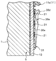
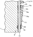
- FIG. 4 is a sectional view taken along line IV-IV shown in FIG. 2.
- FIG. 5 is a sectional view taken along line VV shown in FIG. 3.
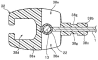
- FIG. 3 is a cross-sectional view taken along line VII-VII shown in FIG.
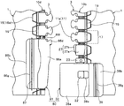
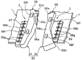
- FIG. 6 is a plan view showing the main parts of a right element member and a box member that can be used in place of the right element member and the box member of Examples 1 to 3. It is a perspective view of a box member. It is a top view which shows typically the principal part of the product (clothing) with a slide fastener which concerns on Example 4 of this invention. It is a perspective view which shows typically the butterfly stick part and box stick part of Example 4.
- FIG. 6 is a plan view showing the main parts of a right element member and a box member that can be used in place of the right element member and the box member of Examples 1 to 3.
- It is a perspective view of a box member. It is a top view which shows typically the principal part of the product (clothing) with a slide fastener which concerns on Example 4 of this invention. It is a perspective view which shows typically the butterfly stick part and box stick part of Example 4.
- FIG. 6 is a plan view showing the main parts of a right element member and a box member that can be used in
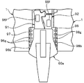
- Example 4 it is a top view which shows the positional relationship of the butterfly stick part of the state which meshed
- the product with a slide fastener is a garment with a slide fastener
- the product with a slide fastener according to the present invention is not limited to clothes (clothing), but shoes
- Various products such as daily miscellaneous goods such as foods and potatoes, products such as industrial materials, and various seats such as automobiles, trains, and airplanes are included.
- the opening and closing tool described in each of the following embodiments is provided with a butterfly pin portion on the left side when the garment that is the product is viewed from the front side, and a box portion or a box rod portion on the right side.
- the box part is arranged, and a person who wears the clothes is formed as a so-called right-and-left separating and inserting tool for operating the butterfly stick part with the right hand.
- the so-called left-side separation fitting is formed in a product with a slide fastener by reversing the positional relationship between the butterfly pin and the box in the left-right direction from the following embodiments. It is also possible.
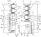
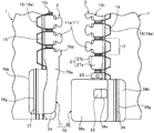
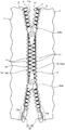
- FIG. 1 is a plan view schematically showing a main part of a garment with a slide fastener according to the first embodiment
- FIG. 2 is a plan view showing a state in which the separation / insertion tool is separated from the main part of the garment. It is.
- FIG. 3 and FIG. 6 are side views of the placket part of the garment provided with the butterfly bar part and the box part of the separation / insertion tool as seen from the mating counterpart side.
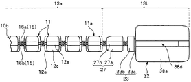
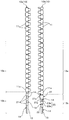
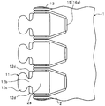
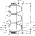
- FIG. 8 is a plan view showing the left and right element members.
- the front-rear direction refers to the length direction of the element member parallel to the sliding direction of the slider, and in particular, the direction in which the slider slides so as to mesh the left and right element rows is the front, The direction of sliding so as to separate the left and right element rows is the rear.
- the front and back can also be paraphrased as the direction which leaves
- the left-right direction refers to the width direction of the element member (or the width direction of the cloth serving as the fastener attaching member), for example, the direction orthogonal to the sliding direction of the slider and parallel to the front and back surfaces of the cloth. is there.
- the vertical direction means a direction perpendicular to the front-rear direction and the left-right direction, for example, the thickness direction of the element member orthogonal to the front and back surfaces of the fabric.
- the direction on the side where the slider handle is arranged with respect to the element member is defined as the upper side, and the direction on the opposite side as the lower direction.
- the product with the slide fastener according to the first embodiment is a garment (clothing) with a slide fastener, and the element member 10 is formed on the cloth 1 that forms the front body (particularly, the front part) serving as an opening / closing part in the garment.
- Left and right element mounting edges 2 to be mounted are arranged.
- the left and right element rows 3 are formed by sewing element members 10 on the left and right element mounting edges 2 of the garment.
- a separation fitting 30 having a butterfly pin portion 31 and a box portion 32 is attached to the rear end portions (lower end portions in the drawing of FIG. 1) of the left and right element attachment edge portions 2. Further, a single slider 60 is slidably attached to the left and right element rows 3 along the element row 3, and the slider 60 is slid forward or backward along the element row 3.
- the front part (opening / closing part) of the front body on the left and right sides of the clothes can be closed or opened by the engagement or separation of the left and right element rows 3.
- the fabric 1 (also referred to as garment fabric) constituting the front body of the garment is a fastener attaching member to which the element member 10 is attached.
- the slide fastener configured in the first embodiment includes a pair of left and right fastener stringers including an element row 3 formed by directly fixing the element member 10 to the cloth 1 of the clothes, and elements of the left and right fastener stringers. It has a slider 60 capable of meshing and separating the rows 3 and an opening / closing insert 30 arranged adjacent to the rear ends of the left and right element rows 3.
- Cloth 1 used as a fastener attaching member has performance and properties (softness, thickness, texture, color, etc.) necessary for clothes.
- the fabric 1 to which the element member 10 is sewn is cut into a predetermined shape and size according to the shape and design of clothes.
- the thickness of a general conventional fastener tape is 1.1 mm to 1.5 mm
- the fabric 1 that is a fastener attaching member used in Example 1 and other portions of the fabric are as follows. From the viewpoint of weight reduction, it is formed thin, and has a thickness of, for example, 0.2 mm to 1.0 mm, preferably 0.4 mm to 0.7 mm.
- the left and right element mounting edges 2 provided on the fabric (fastener attaching member) 1 are linearly arranged at positions facing each other on the front body of the garment (that is, facing edges of the placket). And it is arranged continuously. Further, as will be described later, in the first embodiment, the left and right member mounting portions 5 are formed by fixing the extending portions 13b of the fixing member 13 of the element member 10 to the left and right element mounting edges 2. These left and right member mounting portions 5 are also arranged at positions facing each other.
- the left and right element attachment edges 2 are formed by folding back side edges that are the cut ends of the fabric 1 into a U shape in the width direction of the element member 10. .
- the element attachment edge 2 is formed locally thicker than the other portions of the thin fabric 1 and the strength of the element attachment edge 2 is increased. it can. Thereby, it becomes difficult to cut
- the element member 10 and the release fitting 30 can be firmly fixed to the element mounting edge 2.
- the side edge of the fabric 1 is folded in a U-shape, so that, for example, even if the side edge of the fabric 1 is unraveled, the unraveling is hidden on the back side of the element mounting edge 2 and You can prevent it from appearing. Thereby, the clothes with a slide fastener can be provided with good appearance quality (appearance). Further, it is possible to prevent the meshing of the left and right element rows 3 from being deteriorated and the slidability of the slider 60 from being lowered due to the unraveling occurring at the side edge of the fabric 1.
- the configuration of the clothing fabric 1 is not particularly limited, and can be appropriately changed according to the usage of the clothing.
- the element member 10 includes a left element member 10 a (also referred to as a first element member) on which a butterfly pin portion 31 is provided and a box body portion (box portion) 32. And a right element member 10b (also referred to as a second element member).
- the left element member 10a and the right element member 10b are different in form at the rear end of the element member 10.
- the left and right element members 10a and 10b will be described in detail.
- the left element member 10a includes a plurality of independent fastener elements 11 (also referred to as single fastener elements), a single string-like fixing member 13 that connects the plurality of fastener elements 11 at a constant interval, and a fixing member 13 And three first anchor elements 21 arranged at the rear end portion (extended portion 13b described later).
- the right element member 10b includes a plurality of independent fastener elements 11, a single string-like fixing member 13 that connects the plurality of fastener elements 11 at a constant interval, and a rear end portion of the fixing member 13 ( There are two types of second anchor element 22 and third anchor element 23 arranged in the extending part 13b), and a box side insertion part 27 arranged in the rear end part.
- each fastener element 11 disposed on the left element member 10a and each fastener element 11 disposed on the right element member 10b are formed in a bilaterally symmetric shape, but are substantially the same. It has a structure.
- the plurality of fastener elements 11 arranged on the element members 10 a and 10 b are aligned in a line along the length direction of the element member 10 in a state where the fastener elements 11 are connected at equal intervals by the fixing member 13.
- These fastener elements 11 are formed integrally with the fixing member 13 by injection molding a thermoplastic resin such as polyamide, polyacetal, polypropylene, polybutylene terephthalate, etc. into one fixing member 13. 13 is formed so as to cover the entire outer periphery.
- the end on the side where the lengthwise separation / insertion tool 30 is disposed (in the case of the first embodiment).
- the material of the fastener element 11 is not limited to the above-described synthetic resin.
- the fastener element 11 can be formed of other synthetic resin or metal.
- the element member 10 of the first embodiment is not limited to the one in which the fastener element 11 is formed by injection molding a thermoplastic resin on the fixing member 13.
- the element member 10 is formed by injection molding a thermoplastic resin to a predetermined shape. The element formed in (1) is fixed to the fixing member 13 by welding or adhesion.
- the element member 10 in the present invention is not limited to the one in which the synthetic resin-made fastener element 11 made of an injection molding is integrally formed and connected to the fixing member 13 as in the first embodiment.
- the element member of the present invention includes, for example, an element member formed by performing metal die casting on a string-like fixing member 13 and a wire rod (so-called Y bar) having a substantially Y-shaped cross section. Further, the element is formed by attaching the element to the fixing member 13 by pressing deformation, and the element is formed by punching a thin plate member, and the element is further attached to the fixing member 13 by pressing deformation. Element members to be used.
- the fastener element 11 has a trunk portion 12 a fixed to the fixing member 13, and continuously extends in the width direction of the element member 10 from the trunk portion 12 a and has a length.
- a neck portion 12b having a constricted shape so that the dimension in the direction becomes narrower, a meshing head portion 12c extending continuously from the neck portion 12b in the width direction and having a substantially oval shape in plan view, and a front side from the neck portion 12b
- a protruding piece 12d also referred to as a shoulder protruding rearward.
- the trunk portion 12a of the fastener element 11 has a substantially rectangular parallelepiped shape with a constant thickness, and is formed so as to wrap around the fixing member 13 so that the fixing member 13 penetrates in the front-rear direction.
- An insertion recess 12e into which a part of the element attachment edge 2 of the fabric 1 is inserted is provided along the length direction of the element member 10 on the side surface portion of the body portion 12a facing the fabric 1. .
- the element member 10 is fixed to the element mounting edge 2 by the fixing sewing portion 15 in a state where the element mounting edge 2 of the fabric 1 is inserted into the insertion recess 12e, so that each fastener element 11 is in a predetermined direction. With this, the element mounting edge 2 can be firmly and stably fixed.
- the fixing member 13 has penetrated along the length direction in the state enclosed by the trunk
- a concave groove portion 12f is formed at the top end portion (tip portion) of the meshing head portion 12c along the length direction so as to fit the protruding piece portion 12d of the mating counterpart fastener element 11 when the left and right element rows 3 are meshed.
- the shape of the fastener element 11 is not particularly limited, and can be arbitrarily changed.
- the left and right fixing members 13 in the first embodiment are formed of the same string-like member that is flexible and has a substantially circular cross section perpendicular to the length direction.
- each fixing member 13 is preferably a member having a circular cross section and a constant cross-sectional area in the length direction.
- Such a fixing member 13 is formed, for example, by wrapping a monofilament, a twisted yarn (twisted string), or a core yarn composed of a plurality of aligned multifilaments in a bag weave knitted with a plurality of knitting yarns. It is possible to use a cord body (also referred to as a knit cord).
- the fixing member 13 used in the present invention is not particularly limited as long as a plurality of elements can be attached. Further, the cross-sectional shape of the fixing member 13 can be arbitrarily changed as necessary. Furthermore, the element member 10 of the present invention may be formed by connecting a plurality of elements by two or more string-like fixing members 13.
- the fixing member 13 has an element holding portion 13a to which a plurality of fastener elements 11 are attached at equal intervals in the longitudinal direction of the element member 10, and further to the rear than the end fastener element 11a described above. And an extending portion 13b that extends. In other words, the extending portion 13 b of the fixing member 13 continuously extends rearward from the element holding portion 13 a of the fixing member 13.
- the three first members used for positioning the butterfly pin member 36 are used.
- An anchor element 21 is arranged.
- arranged in the extension part 13b on the left side is formed as the exposed part 14 which the extension part 13b exposes.
- the overall length including the exposed portion 14 of the left extension 13b is larger than the size of the mounting pitch of the plurality of fastener elements 11 attached at equal intervals in the length direction, preferably It is set to be larger than twice the size of the mounting pitch.
- the attachment pitch (interval) of the fastener elements 11 is an interval in the length direction between predetermined positions (for example, center positions) in the length direction of the fastener elements 11 in the fastener elements 11 adjacent to each other in the length direction. Say (dimensions).
- the three first anchor elements 21 in the first embodiment are arranged in order from the end fastener element 11a described above at the same attachment interval as the attachment interval (attachment pitch) of the fastener elements 11 in the left element member 10a. ing. That is, in the left element member 10a, the plurality of fastener elements 11 and the three first anchor elements 21 are intermittently and regularly aligned with a certain interval along the length direction.
- the exposed portions 14 provided on the left extending portion 13b are also intermittently arranged at regular intervals along the length direction. By forming the exposed portion 14 in the extended portion 13b, a part of the exposed portion 14 is held by being held in a sewing thread of a fixing sewing portion 15 to be described later, thereby the left extended portion. 13 b is stably fixed to the element mounting edge 2 of the fabric 1.
- the left element member 10a is used with the staggered sewing machine with respect to the element mounting edge 2 of the fabric 1.
- the zigzag fixing sewing portion 15 is formed, the zigzag sewing sewing machine needle is not interfered with the fastener element 11 or the first anchor element 21, and the element holding portion 13a of the fixing member 13 is formed.
- the region of the extending portion 13b can be sewn and fixed to the element attachment edge portion 2 with the same stitch pattern.
- the number of the first anchor elements 21 to be installed is, for example, the length dimension of the extending portion 13b. It can change arbitrarily according to etc.
- the first anchor element 21 of the first embodiment bulges from the extending portion 13b of the fixing member 13 in the radial direction of the fixing member 13 and partially wraps the extending portion 13b of the fixing member 13 from the outside. It has a columnar shape.
- the first anchor element 21 has a cylindrical shape centering on the central axis along the length direction of the fixing member 13 whose cross section is circular or substantially circular.
- the transverse section refers to a section orthogonal to the length direction. For this reason, when the cross section of the first anchor element 21 is viewed, the first anchor element 21 bulges out from the fixing member 13 in a donut shape in the radial direction.
- the dimension of the first anchor element 21 that bulges in the radial direction is the same size on the entire circumference of the first anchor element 21.
- the first anchor element 21 of the first embodiment may have a spherical or hemispherical shape, or a shape obtained by combining at least two of a cylindrical shape, a spherical shape, or a hemispherical shape. . Since the first anchor element 21 has such a shape, even if the fixing member 13 is twisted, the shape (orientation) of the first anchor element 21 itself does not change. The positioning function of the butterfly pin member 36 and the effect of improving the attachment strength of the butterfly pin portion 31 by housing the first anchor element 21 in the butterfly rod portion 31 can be exhibited appropriately and stably. In the present invention, the first anchor element 21 may be formed in other shapes such as a prismatic shape or the shape of the body 12a of the fastener element 11 described above.
- the extending portion 13b of the fixing member 13 in the right element member 10b includes, as shown in FIG. 8, a rear second anchor element 22, a front third anchor element 23, a third anchor element 23, Box body side insertion portions 27 arranged between the end fastener elements 11a are respectively provided at predetermined positions.
- a portion where neither the second anchor element 22 nor the third anchor element 23 is arranged is formed as an exposed portion 14 on the right extending portion 13b, and a part of the exposed portion 14 is sewn for fixing.
- the right extending portion 13 b is stably fixed to the element mounting edge 2 of the fabric 1.
- the entire length including the exposed portion 14 of the right extension 13b is larger than the size of the mounting pitch between the two fastener elements 11 adjacent in the length direction, and preferably the size of the mounting pitch is large. It is set to be larger than twice.
- the second anchor element 22 and the third anchor element 23 of the first embodiment are used for positioning the box member 38 when the box member 38 is attached as a box member as will be described later.
- the box-side insertion portion 27 is accommodated in an element guide path (to be described later) of the slider 60 when the butterfly pin portion 31 is accommodated in the box body portion 32 and the left and right element rows 3 are engaged with each other.
- the positional relationship between the butterfly bar portion 31 and the box body portion 32 is stabilized by being inserted into a later-described butterfly rod side recess 36e.
- the predetermined positions in the second anchor element 22, the third anchor element 23, and the box side insertion portion 27 are the right element member 10b and the zigzag stitch sewing machine as in the case of the left element member 10a.
- the sewing needle is caused to interfere with the second anchor element 22, the third anchor element 23, and the box side insertion portion 27 when the zigzag fixing sewing portion 15 is attached to the element attachment edge 2 of the fabric 1.
- the position of the element holding portion 13a and the region of the extending portion 13b of the fixing member 13 can be sewn with the same stitch pattern.
- the 2nd anchor element 22 of the present Example 1 is distribute
- the second anchor element 22 has a columnar shape that bulges from the extending portion 13 b of the fixing member 13 in the radial direction of the fixing member 13 and wraps around the extending portion 13 b of the fixing member 13.
- the third anchor element 23 is arranged at a position between the second anchor element 22 and the box side insertion portion 27 in the length direction.
- the third anchor element 23 is integrally formed with a cylindrical portion 23a having a cylindrical shape that bulges in the radial direction of the fixing member 13 from the extending portion 13b of the fixing member 13, and the cylindrical portion 23a above the cylindrical portion 23a.
- a diameter-enlarged portion 23b having a truncated cone shape that bulges in the radial direction from the cylindrical portion 23a.
- the cylindrical portion of the third anchor element 23 is formed slightly thinner than the cylindrical second anchor element 22, and a part of the cylindrical portion of the third anchor element 23 is provided with a box body portion 32. Sometimes it is housed in the box body 32 (specifically, a box-side anchor housing recess 38f to be described later of the box body section 32) and cannot be seen from the outside.
- the second anchor element 22 and the third anchor element 23 of the first embodiment have a spherical or hemispherical shape, or a shape obtained by combining at least two of a cylindrical shape, a spherical shape, or a hemispherical shape. It may also have other shapes such as a prismatic shape, the shape of the body 12a of the fastener element 11 described above, and the overall shape of the fastener element 11 depending on circumstances.
- the box-side insertion portion 27 has a rectangular columnar fixing portion 27a fixed to the fixing member 13, and a thin plate-like insertion piece portion 27b protruding from the fixing portion 27a in the width direction of the element member 10.
- the insertion piece portion 27 b has a shape that exhibits a substantially trapezoidal shape in a plan view of the element member 10.
- the first anchor element 21 to the third anchor element 23 and the box side insertion portion 27 described above are formed by injection-molding the same thermoplastic resin as the fastener element 11 to each fixing member 13, It is integrally formed.
- the injection molding of the first anchor element 21 to the third anchor element 23 and the box side insertion portion 27 may be performed simultaneously with the injection molding of the fastener element 11 or may be performed separately from the injection molding of the fastener element 11. .
- the materials of the first anchor element 21 to the third anchor element 23 and the box side insertion portion 27 are not particularly limited, and these portions may be formed of a synthetic resin or metal different from the fastener element 11. .
- a molded body of the first anchor element 21 to the third anchor element 23 and the box side insertion portion 27 formed in advance by injection molding of a thermoplastic resin into a predetermined shape is welded or bonded to the fixing member 13. It is also possible to fix.
- the left side element member 10a and the right side element member 10b in the first embodiment as described above are arranged at positions adjacent to the outer sides in the width direction with respect to the element mounting edge portions 2 of the left and right fabrics 1, respectively.
- the fixing sewing part (fixing sewing line) 15 fixes the sewing machine.
- the fixing sewing portion 15 is formed by sewing a staggered sewing machine, and is formed by bending in a zigzag shape in the length direction by main sewing.
- the left and right element members 10 are fixed to the element mounting edge 2 in a state where at least the body 12 a of each fastener element 11 is in contact with the element mounting edge 2 of the fabric 1.
- the extending portion 13b of the fixing member 13 is fixed to the element mounting edge 2 in a state where at least the respective anchor elements 21, 22, and 23 are in contact with the element mounting edge 2 of the fabric 1.
- the staggered sewing machine is a sewing machine that can sew the fabric 1 and the like in a zigzag manner by swinging the sewing needle along the crossing direction that intersects the feed direction of the sewing machine.
- the swinging of the sewing needle in the staggered sewing machine is sometimes referred to as staggered swing.
- staggered swing While using such a staggered sewing machine, for example, set the coordinate data of the X coordinate (position in the feed direction) and the Y coordinate (position in the cross direction) as the needle drop position of the sewing needle to the staggered sewing machine.
- the sewing thread of the fixing sewing portion 15 formed by the main sewing is an upper thread that runs on the surface (first surface) of the element attachment edge portion 2 and contacts the surface side half of the fixing member 13.
- (Needle thread) 16 a and lower thread (bobbin thread) 16 b that travels on the back surface (second surface) of the element mounting edge 2 and contacts the back surface side half of the fixing member 13.
- the fixing sewing portion 15 is formed by the main sewing, the upper thread 16a and the lower thread 16b are arranged in a plane-symmetrical positional relationship.
- the upper thread 16a and the lower thread 16b of the main stitch are a piercing position where the fixing sewing portion 15 pierces the element mounting edge 2 (a first piercing position 18a and a second piercing position 18b described later). 3 and FIG. 6 and the position in contact with the outer peripheral surface of the fixing member 13 cross each other (entanglement).
- the upper thread 16a and the lower thread 16b of the sewing part 15 for fixing are an upper thread 16a that travels on the surface of the element mounting edge 2 and a lower thread 16b that travels on the back surface of the element mounting edge 2 in the thickness direction.
- the upper thread 16a and the lower thread 16b in the first embodiment intersect each other at the position of the central portion in the thickness direction of the element mounting edge 2.
- the crossing position of the upper thread 16a and the lower thread 16b in the thickness direction can be easily changed by controlling the tension of the upper thread 16a and the lower thread 16b in the staggered sewing machine.
- the fixing sewing portion 15 is formed by stitches of main stitches for racing the upper thread 16a and the lower thread 16b with other threads using the staggered sewing machine as described above. As a result, the fixing sewing portion 15 penetrates the element attachment edge portion 2 of the fabric 1 and the upper thread 16a and the lower thread 16b are brought into contact with the outer peripheral surface of the fixing member 13 of the element member 10 while the fixing member 13 is moved. Can be supported to wrap. Therefore, the element member 10 is easily and stably attached and fixed to the element attachment edge portion 2 of the fabric 1 by the fixing sewing portion 15.
- the upper thread 16a and the lower thread 16b of the fixing sewing portion 15 after sewing are made to the surface of the fastener element 11 with respect to the fastener element 11 ( It can prevent effectively that it arrange
- the fixing sewing portion 15 is configured so that the upper thread 16a and the lower thread 16b of the main sewing intersect the following on the outer peripheral surface of the fixing member 13 with respect to one fastener element 11 from the outer periphery intersecting position. It has a unit travel region 17 that travels to an outer periphery crossing position that intersects on the outer peripheral surface of the fixing member 13, and a seam of the unit travel region 17 is repeatedly arranged for each fastener element 11 in the length direction.
- the seam of each unit travel region 17 forming the fixing sewing portion 15 of the first embodiment has two piercing positions at which the fixing sewing portion 15 pierces the element attachment edge portion 2.
- the seam pattern in the unit travel region 17 is not limited to the region where the fastener element 11 of the element member 10 is disposed, but also the extended portion 13b of the fixing member 13 where the fastener element 11 is not disposed.
- the extension portion 13b of the fixing member 13 is fixed to the element attachment edge portion 2.
- the upper thread 16a and the lower thread 16b of the fixing sewing portion 15 in the first embodiment are fixed to the fixing member 13 in each unit traveling region 17.
- a first traveling portion 17a that is arranged from the outer circumferential intersection position where the upper thread 16a and the lower thread 16b intersect on the outer circumferential surface to the first first piercing position 18a, and the second second piercing from the first piercing position 18a. It has the 2nd driving
- the first traveling portion 17a is configured so that the upper thread 16a (or the lower thread 16b) extends in the width direction (or substantially in the width direction) from the above-described outer circumferential intersection position to the position in the width direction corresponding to the side surface portion of the fastener element 11.
- the first piercing position 18a is formed by traveling obliquely with respect to the width direction.
- the boundary portion between the portion traveling along the width direction of the first traveling portion 17a and the portion traveling obliquely with respect to the width direction may be in contact with the body portion 12a of the fastener element 11.
- the second traveling portion 17b is formed by the upper thread 16a (or the lower thread 16b) traveling along the length direction of the element member 10 between the first piercing position 18a and the second piercing position 18b. Is done.
- the third traveling portion 17c travels obliquely with respect to the width direction from the second piercing position 18b to the position in the width direction corresponding to the side surface portion of the fastener element 11, and the outer thread 16a (or the lower thread 16b) travels obliquely with respect to the width direction.
- the intersection is formed by traveling along the width direction (or substantially the width direction). In this case, the boundary between the portion that travels obliquely with respect to the width direction of the third traveling portion 17 c and the portion that travels along the width direction may be in contact with the body portion 12 a of the fastener element 11.
- the first piercing position 18a and the second piercing position 18b through which the fixing sewing portion 15 pierces the element mounting edge 2 of the fabric 1 are separated from the inner side surface portion of each fastener element 11 by a width. It is formed so as to be separated toward the inner side of the fabric 1 in the direction (in other words, the direction opposite to the direction facing the fastener element 11 on the engagement partner side). That is, in the width direction of the element member 10, a fixed interval is provided between the first and second piercing positions 18 a and 18 b of the fixing sewing portion 15 and the position of the side surface portion of each fastener element 11. ing.
- the positions of the first and second piercing positions 18a and 18b of the fixing sewing portion 15 By setting the positions of the first and second piercing positions 18a and 18b of the fixing sewing portion 15 in this way, the upper thread 16a and the lower thread 16b of the fixing sewing portion 15 are placed on the front and back surfaces of the fastener element 11. Overlap can be prevented more stably. Moreover, the space
- the dimension in the length direction of the unit traveling region 17 of the fixing sewing portion 15 is set to the same size in the region of the element holding portion 13a and the region of the extending portion 13b in the fixing member 13. ing.
- the unit of the fixing sewing portion 15 is fixed between the region of the element holding portion 13a and the extension portion 13b of the fixing member 13. It is also possible to vary the lengthwise dimension in the travel region 17.
- the lengthwise dimension can be varied for each unit travel region 17 of the fixing sewing portion 15.
- the position of the side surface portion of each fastener element 11 in the width direction and the piercing position of the fixing sewing portion 15 (first piercing position 18a and second piercing position 18b).
- a supplementary sewing portion 19 for continuously tightening the upper thread 16a and the lower thread 16b of the fixing sewing portion 15 so as not to loosen is formed in a region between them.
- the auxiliary sewing portion 19 has a length of the element member 10 by stitches of the main sewing that performs the other thread racing of the auxiliary upper thread (needle thread) and the auxiliary lower thread (bobbin thread) using a sewing machine. It is formed linearly along the vertical direction.
- the auxiliary sewing portion 19 By forming the auxiliary sewing portion 19 by the main stitch in this manner, the auxiliary sewing portion 19 can be easily and stably formed, and the upper thread 16a and the lower thread 16b of the fixing sewing portion 15 can be stably pressed. (Tighten).
- the auxiliary upper thread and the auxiliary lower thread of the auxiliary sewing portion 19 are the piercing position where the auxiliary sewing portion 19 pierces the element mounting edge 2 and the thickness direction at the element mounting edge 2 Are crossed (entangled) with each other at the position of the central portion.
- the crossing position of the auxiliary upper thread and the auxiliary lower thread in the thickness direction can be changed by controlling the tension of the auxiliary upper thread and the auxiliary lower thread in the sewing machine.
- the auxiliary upper thread and the auxiliary lower thread are fixed to the fixing sewing portion in the region overlapping the first traveling portion 17a and the third traveling portion 17c in the fixing sewing portion 15. 15 on the upper thread 16a and the lower thread 16b.
- the upper thread 16 a and the lower thread 16 b of the fixing sewing portion 15 are directed to the element mounting edge 2 from above and below with the auxiliary upper thread and the auxiliary lower thread. It can be pressed down (in other words, toward the inside in the thickness direction). Thereby, the upper sewing thread 16a and the lower sewing thread 16b can be tightened by the auxiliary sewing section 19 to apply tension. For this reason, even if slack has arisen in the upper thread 16a and the lower thread 16b of the sewing part 15 for fixation, the slack can be eliminated. Further, it is possible to effectively prevent the upper thread 16a and the lower thread 16b of the fixing sewing portion 15 from being loosened.
- the auxiliary sewing portion 19 is formed by linear main sewing along the length direction.
- the auxiliary sewing portion 19 includes the upper thread 16a of the fixing sewing portion 15 and the upper thread 16a. If the lower thread 16b can be pressed toward the element attachment edge 2, the auxiliary sewing portion 19 can be formed by stitches other than the main stitch such as double chain stitch.
- the left and right fabric 1 are formed along the element mounting edge 2.
- extension portion 13b of the fixing member 13 in the left element member 10a is fixed to the element attachment edge portion 2 of the left fabric 1 by the fixing sewing portion 15 and the auxiliary sewing portion 19, whereby the left fabric 1 A member mounting portion that is formed on the rear side edge portion by the extending portion 13b of the fixing member 13 and a part of the element mounting edge portion 2, and to which the butterfly pin member 36 of the separation fitting 30 is mounted. 5 is formed.
- the fixing portion 15 b and the auxiliary sewing portion 19 fix the extending portion 13 b of the fixing member 13 of the right element member 10 b to the element attachment edge 2 of the right fabric 1, thereby allowing the right fabric 1
- a box member 38 is attached to the rear side edge portion by the extended portion 13 b of the fixing member 13 and a part of the element attachment edge portion 2 as a box member of the separation fitting 30.
- a member mounting portion 5 is formed.
- the split fitting tool 30 of the first embodiment includes a butterfly bar portion 31 provided on the member attachment portion 5 of the left-side fabric 1, a box portion 32 provided on the member attachment portion 5 of the right-side fabric 1, and the above-described components.
- Box-side insertion portion 27 In the present invention, instead of the box part 32 and the box side insertion part 27, it is also possible to form a box part with a box stick in which the box stick part is integrally formed in the box part as described later. It is.
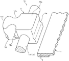
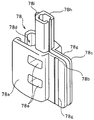
- the butterfly stick portion 31 of the first embodiment is obtained by attaching a butterfly stick member 36 made of synthetic resin such as nylon to the above-described member attaching portion 5 formed at the lower end portion of the left-side fabric 1 and the opposite side edge portion. Formed by.
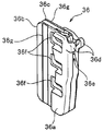
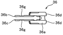
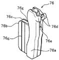
- the butterfly pin member 36 of the first embodiment is one of the constituent parts that form the separation / insertion tool 30. As shown in FIGS. 10 to 12, the wing pin member 36 includes a wing pin main body portion 36a that wraps a part of the extending portion 13b of the fixing member 13 along the fixing member 13, and a wing pin main body portion 36a side.
- the second butterfly fin portion 36c disposed on the lower surface (second surface) of the element mounting edge 2 and the front end portion of the butterfly rod main body portion 36a are integrally provided, and the end portion of the right element member 10b. It has a meshing part 36d that meshes with the fastener element 11a.
- the butterfly pin main body portion 36 a is provided with an accommodation holding portion (internal space portion) that accommodates and wraps a part of the member attachment portion 5 formed on the fabric 1.
- a cross section orthogonal to the length direction has a substantially U-shape.
- the butterfly body insertion portion 27 of the right element member 10b is inserted and accommodated in the opposite side surface portion of the butterfly rod body portion 36a facing the box body portion 32.
- a rod-side recess 36e is formed along the length direction.
- three upper surface side anchor accommodation holes 36f for accommodating the first anchor elements 21 are provided in the length direction at the connecting portion where the wing pin main body portion 36a and the upper surface side first wing pin fin portion 36b are connected. It is regularly provided with a predetermined interval.
- three lower surface side anchor receiving hole portions 36f for storing the first anchor elements 21 are also provided at the connecting portion where the bar main body portion and the second butterfly stick fin portion 36c on the lower surface side are connected as shown in FIG. Are provided in the same manner as the upper surface side anchor accommodating hole 36f.
- the fixing sewing part, the auxiliary sewing part, and the butterfly pole side sewing part The illustration of each sewing part such as is omitted.
- the upper surface side and the lower surface side anchor accommodating hole 36f are arranged at positions corresponding to each other and have a width dimension larger than the width dimension (dimension in the width direction) of the first anchor element 21.
- the butterfly rod member 36 is used.
- the upper surface of the first butterfly fin portion 36b and the lower surface of the second butterfly fin portion 36c of the butterfly rod member 36 accommodate a butterfly rod side sewing portion 37, which will be described later, formed when the butterfly rod member 36 is fixed.
- An accommodation concave groove portion 36g is provided along the length direction.
- the receiving groove portion 36g of the first butterfly fin portion 36b and the receiving groove portion 36g of the second butterfly fin portion 36c are formed at the same corresponding positions of the butterfly rod member 36 in the width direction. .
- a butterfly pin member in which the second butterfly fin portion 36c described above is excluded from 36 can also be used.
- the butterfly pin member 36 of the first embodiment When the butterfly pin member 36 of the first embodiment is attached to the member attachment portion 5 formed on the left-side fabric 1, first, the butterfly pin member 36 is connected to the first butterfly fin portion 36b and the second butterfly fin portion 36c.
- the member mounting portion 5 of the fabric 1 is elastically deformed so that the gap is slightly opened so that the member mounting portion 5 is inserted between the first butterfly fin portion 36b and the second butterfly fin portion 36c. Put on.
- the extending portion 13b of the fixing member 13 is inserted and accommodated in the above-described accommodation holding portion of the butterfly rod main body portion 36a, and the butterfly rod main body portion 36a is fixed to the fixing member. 13 wraps at least part of the outer periphery of the extending portion 13b. Further, the three first anchor elements 21 provided in the extending portion 13b of the fixing member 13 are connected to the three upper surface side anchor receiving hole portions 36f formed on the first butterfly pin fin portion 36b side of the butterfly rod member 36, and Then, it is inserted and accommodated in three lower surface side anchor accommodation holes 36f formed on the second butterfly fin portion 36c side.
- the butterfly pin member 36 can be easily and stably positioned at a predetermined position with respect to the member mounting portion 5 of the fabric 1, and the position of the butterfly pin member 36 can be prevented from shifting in the length direction and the width direction.
- the butterfly pin member 36 can be temporarily fixed temporarily at that position.
- the upper and lower anchor receiving holes 36f of the butterfly pin member 36 open to the outer surface of the butterfly pin member 36, and the first anchor element is interposed via the upper and lower anchor receiving holes 36f.
- the position 21 can be visually confirmed. For this reason, the said positioning of the butterfly stick member 36 can be performed easily and rapidly.
- a butterfly pin side sewing portion 37 is formed,
- the first butterfly pin fin portion 36b and the second butterfly rod fin portion 36c of the butterfly pin member 36 are sewn and fixed to the member mounting portion 5 of the fabric 1 by the butterfly pin side sewing portion 37.
- the butterfly bar side sewing portion 37 is formed linearly along the length direction of the element member 10 by stitches of main stitches that perform upper thread (needle thread) and lower thread (bobbin thread) racing with other threads. In this case, it is preferable that the butterfly bar side sewing portion 37 is formed by performing reverse stitching, thereby making it difficult to cause the end of the butterfly rod side sewing portion 37 to be unraveled.
- the sewing needle is inserted into the receiving groove portion 36g of the first butterfly fin portion 36b and the receiving groove portion 36g of the second butterfly fin portion 36c.
- the butterfly pin side sewn portion 37 can be formed in the accommodating groove portion 36g of the first butterfly rod fin portion 36b and the accommodating groove portion 36g of the second butterfly rod fin portion 36c. Since the butterfly pin member 36 is thinly formed in the accommodating groove portion 36g of the first butterfly fin portion 36b and the accommodating groove portion 36g of the second butterfly fin portion 36c, a sewing needle is inserted into the butterfly rod member 36.
- the butterfly pin side sewn portion 37 is accommodated in the accommodating recess groove portion 36g of the first butterfly pin fin portion 36b and the accommodating recess groove portion 36g of the second butterfly rod fin portion 36c. It is possible to make it difficult to make the upper and lower flange portions, which will be described later, of the slider 60 come into contact with each other, thereby making it difficult to cause thread breakage in the butterfly pin side sewing portion 37.
- the butterfly pin side sewing portion 37 is formed by the sewing machine, and the member mounting portion 5 and the butterfly pin member 36 of the fabric 1 are sewn together, so that the butterfly rod member 36 of the member mounting portion 5 of the fabric 1 is sewn.
- the butterfly pin 31 formed from the butterfly pin member 36 is fixed to a predetermined position, and the end element 11a of the left element row 3 is attached to the fabric 1 to which the left element member 10a is attached. Adjacent and can be appropriately provided so as to continue from the left element row 3 along the length direction.
- the attachment strength of the butterfly stick part 31 to the fabric 1 is increased, It is possible to make it difficult for the butterfly stick 31 to fall off the fabric 1.
- the butterfly rod body portion 36a is disposed in an element guide path (described later) of the slider 60 when the butterfly pin member 36 is fixed to the member mounting portion 5. It is formed to have a height dimension that can be inserted into the. Particularly in the case of the first embodiment, the maximum value of the height dimension of the butterfly pin main body 36 a is set to the same size as the height dimension of the fastener element 11. In the present invention, it is preferable that the height dimension of the butterfly pin main body 36a is the same as the height dimension of the fastener element 11, but a range of ⁇ 20% relative to the height dimension of the fastener element 11 is used. It only has to be set within.
- first butterfly rod fin portion 36b on the upper surface side and the second butterfly rod fin portion 36c on the lower surface side are provided on the butterfly rod portion 31 of the first embodiment.
- first butterfly fin portion 36b and the second butterfly fin portion 36c are sewn to the member attaching portion 5 of the cloth 1, the member attaching portion 5 is protected and the member attaching portion 5 itself is hardly unraveled. can do.
- first butterfly fin portion 36b and second butterfly fin portion 36c the rigidity of the opposite edge portion on the rear end side of the fabric 1 is enhanced by the sewn first butterfly fin portion 36b and second butterfly fin portion 36c.
- the upper surface of the first butterfly fin portion 36b and the lower surface of the second butterfly fin portion 36c are arranged at a height position closer to the fabric 1 through a step than the upper and lower surfaces of the butterfly rod main body portion 36a. Yes.
- the height dimension from the upper surface of the first butterfly fin portion 36 b to the lower surface of the second butterfly fin portion 36 c in the butterfly rod portion 31 can be inserted into the insertion gap formed between the upper and lower flanges of the slider 60.
- the size is set.
- the length dimension (dimension in the length direction) and the width dimension (dimension in the width direction) in the first butterfly fin part 36b and the second butterfly fin part 36c are not limited and can be arbitrarily changed. is there.
- a box member 38 made of synthetic resin such as nylon is attached to the above-described member attaching part 5 formed at the rear end part of the right fabric 1 and the opposite side edge part. Formed by.
- the box member 38 of the first embodiment is another component part that forms the separation / insertion tool 30.
- the box member 38 includes a box body portion (box body portion) 38 a that wraps the extending portion 13 b of the fixing member 13 along the fixing member 13.
- a first box fin 38b extending along the width direction from the side edge of the box body 38a toward the inside of the fabric 1 and disposed on the upper surface (first surface) of the element mounting edge 2;
- a second box fin 38c extending along the width direction from the side edge of the box body 38a toward the inside of the fabric 1 and disposed on the lower surface (second surface) of the element mounting edge 2;
- the box body 38a of the first embodiment has a substantially rectangular parallelepiped or cubic outer shape.
- a butterfly pin housing portion 38d into which the butterfly rod body portion 36a of the butterfly rod portion 31 is inserted and housed is the front end of the box body body portion 38a. It is provided from the edge toward the rear.
- an accommodation holding portion (space portion) that houses and wraps a part of the member mounting portion 5 formed on the fabric 1, and a second part.
- a box-side anchor accommodating hole 38e for accommodating the anchor element 22 and a box-side anchor accommodating recess 38f for accommodating a part of the third anchor element 23 are provided on the upper surface side and the lower surface side of the box body main body 38a. Is provided.
- the box side anchor receiving hole 38e is formed to have a width dimension larger than the width dimension of the second anchor element 22. In this manner, by increasing the width dimension of the box-side anchor receiving hole 38e, the box member 38 is attached in the attachment of the box member 38 to the member attachment portion 5 of the fabric 1 as in the case of the butterfly pin member 36. Since the box side anchor receiving hole 38e can be hardly caught by the second anchor element 22, the box body member 38 can be attached smoothly.
- a box side sewing portion (box side sewing portion) 39 to be described later is provided on the upper surface of the first box fin portion 38 b and the lower surface of the second box fin portion 38 c in the box member 38, as in the case of the butterfly pin member 36.
- a housing groove 38g for housing the housing is provided along the length direction.
- the box member 38 is formed.
- a box member from which the second box fin portion 38c described above is excluded can also be used.
- the box member 38 of the first embodiment When attaching the box member 38 of the first embodiment to the member attachment portion 5 formed on the right side fabric 1, first, the box member 38 is spaced from the first box fin portion 38b and the second box fin portion 38c. Is elastically deformed so as to be slightly opened, and the member attaching portion 5 is sandwiched between the first box fin portion 38b and the second box fin portion 38c, so that the box member 38 is attached to the member attaching portion 5 of the cloth 1. Put on.
- the second anchor element 22 and a part of the third anchor element 23 provided in the extending portion 13b of the fixing member 13 are accommodated in the box side anchor receiving hole 38e and the box side anchor receiving portion of the box member 38.
- the recesses 38f are inserted and accommodated. Accordingly, the box member 38 can be stably positioned at a predetermined position with respect to the member mounting portion 5 of the cloth 1, and the position of the box member 38 can be prevented from shifting in the length direction and the width direction.
- the body member 38 can be temporarily fixed temporarily at that position.
- the box body side sewing portion 39 is connected to the above-described butterfly pin side. It is formed in the same manner as in the case of the sewing portion 37, and the first box fin portion 38 b and the second box fin portion 38 c of the box member 38 are sewn to the box side sewing portion 39 by the box side sewing portion 39. To be fixed. At this time, by forming the box side sewn portion 39 in the housing concave groove portion 36g of the first box fin portion 38b and the housing concave groove portion 36g of the second box fin portion 38c, similarly to the case of the butterfly pin member 36. It is possible to prevent the box member 38 from being damaged and to make it difficult to cause thread breakage in box side sewing.
- the box body member 38 is fixed to a predetermined position of the member mounting portion 5 of the fabric 1 by the box body side sewing section 39, whereby the box body section 32 formed from the box body member 38 is moved to the right side.
- the element member 10b can be appropriately provided on the fabric 1 to which the element member 10b is attached. In this case, since the second anchor element 22 and part of the third anchor element 23 of the right element member 10b are accommodated in the box body portion 32, the attachment strength of the box body portion 32 increases, and the box body portion 32 can be made difficult to fall off the fabric 1.
- the first box fin part 38b and the second box fin part 38c are sewn, so that the rear end side of the fabric 1 is sewn. It is possible to protect the opposite side edge and to prevent the fabric 1 from being unraveled.
- the height dimension from the upper surface of the first box fin portion 38 b to the lower surface of the second box fin portion 38 c in the box body portion 32 is set to a size that can be inserted into the insertion gap formed between the upper and lower flanges of the slider 60.
- the length dimension and width dimension in the 1st box fin part 38b and the 2nd box fin part 38c are not limited, It is possible to change arbitrarily.
- the slider 60 of the first embodiment has a slider body 61 and a handle 66 as schematically shown in FIG. Since the slider body 61 of the first embodiment is formed in substantially the same manner as a conventional general slider body, the detailed structure thereof is omitted, but the slider body 61 includes an upper blade 62 and A lower wing plate spaced from and parallel to the upper wing plate 62, a connecting column connecting the upper wing plate 62 and the front end portion (shoulder side end portion) of the lower wing plate, an upper wing plate 62 and a lower wing plate It has upper and lower flange portions arranged on the left and right side edge portions of the wing plate, and a handle attachment portion 63 arranged on the upper surface of the upper wing plate 62.
- left and right shoulder openings are formed at the front end portion of the slider body 61 with a guide column interposed therebetween, and a rear opening is formed at the rear end portion of the slider body 61.
- a substantially Y-shaped element guide path is formed between the upper wing plate 62 and the lower wing plate to communicate the left and right shoulder openings with the rear opening.
- an insertion gap is formed through which the element mounting edge portion 2 of the fabric 1 is inserted.
- the manufacturing method of the clothes with a slide fastener of the present Example 1 which has the above-mentioned separation fitting 30 is demonstrated.
- the cloth 1 for clothing, the left and right element members 10, and the butterfly bar member 36 and the box member 38 that form the separation / insertion tool 30 are prepared.
- a plurality of fastener elements 11 having a predetermined shape are formed by directly injection-molding synthetic resin into the element holding portion 13a of one string-like fixing member 13. Are formed at equal intervals.
- synthetic resin is directly injection-molded with respect to the extension part 13b of the same fixing member 13, and the three 1st anchor elements 21 are formed in a predetermined position.
- the synthetic resin is directly injection-molded into the element holding portion 13a of the other fixing member 13, and the plurality of fastener elements 11, the second anchor element 22, the third anchor element 23, and the box body
- the side insertion portions 27 are respectively formed at predetermined positions.
- the garment fabric 1 serving as a fastener attaching member is produced by knitting or weaving, and the butterfly bar member 36 and the box member having the predetermined shape as described above. 38 is formed by injection molding of synthetic resin.
- the element attachment edge part 2 is formed by folding back the side edge part used as the cutting edge part in the cut
- the element attachment edge portions 2 respectively formed on the pair of left and right front body fabrics 1 are provided at positions where they are arranged to face each other when the garment is manufactured.
- a sewing process for fixing the element member 10 to the element mounting edge 2 of the fabric 1 is performed using a staggered sewing machine.
- the element holding portion 13a and the extension member in the length direction of the fixing member 13 with respect to the element attachment edge 2 of the element member 10 and the cloth 1 are extended. Sewing by main sewing is performed so that the entire protruding portion 13b is bent in a zigzag shape.
- the element member 10 can be attached (sewn) to the element attachment edge 2 of the fabric 1 while the fixing sewing portion 15 is formed.
- the extending portion 13b of the fixing member 13 is sewn to the element mounting edge 2 of the fabric 1 by the fixing sewing portion 15, so that the butterfly pin member is formed on the opposite side edge at the rear end portion of the left and right fabrics 1.
- Member attachment portions 5 for attaching 36 and the box member 38 are formed.
- an auxiliary sewing portion 19 is formed by using a single-needle lockstitch machine for the element attachment edge portion 2 of the fabric 1 to which the element member 10 is fixed by the fixing sewing portion 15. Perform sewing processing.
- the auxiliary sewing part 19 which consists of the above-mentioned linear main sewing can be stably formed in the predetermined position of the element attachment edge part 2 in which the fixing sewing part 15 is formed. Since the upper thread 16a and the lower thread 16b of the fixing sewing portion 15 are pressed toward the element mounting edge 2 by the auxiliary sewing portion 19, the element member 10 is more firmly fixed to the element mounting edge 2. Can do.
- the butterfly pin member 36 and the box member 38 are attached to the member attachment portions 5 formed at the rear ends of the left and right fabrics 1 as described above. That is, when attaching the butterfly pin member 36, first, the butterfly pin member 36 is elastically deformed so that the distance between the first butterfly fin portion 36b and the second butterfly fin portion 36c is slightly opened, and the member of the fabric 1 The butterfly pin member 36 is put on the upper surface (first surface) and the lower surface (second surface) of the mounting portion 5. At this time, the three first anchor elements 21 provided in the extending portion 13b of the fixing member 13 are inserted into the three upper surface side anchor accommodating hole portions 36f and the lower surface side anchor accommodating hole portion 36f provided in the butterfly pin member 36. The butterfly pin member 36 can be stably positioned at a predetermined position.
- the butterfly pin member 36 (specifically, the butterfly pin side sewing portion 37 is formed in the housing concave groove portion 36g of the first butterfly fin portion 36b and the second butterfly fin portion 36c of the butterfly rod member 36.
- the first butterfly fin portion 36b and the second butterfly fin portion 36c can be sewn to the member mounting portion 5 of the fabric 1 and firmly fixed.
- the butterfly bar portion 31 of the separation / insertion tool 30 is provided so as to be continuous with the left element row 3.
- the box body member 38 When attaching the box member 38, basically the same operation as that of the butterfly pin member 36 is performed. Thereby, the box body member 38 can be sewn to the member mounting portion 5 of the cloth 1 and firmly fixed while the box body side sewing portion 39 is formed in the housing concave groove portion 36 g of the box body member 38. As a result, the box part 32 of the separation fitting 30 is provided behind the right element row 3.
- left and right clothes constituting parts in which the left and right element members 10a and 10b, the butterfly pin member 36, and the box member 38 are attached to the element attaching edge 2 are produced.
- left and right sleeve parts and clothes constituting parts (not shown) constituting the back body are prepared and prepared.
- garment is assembled by joining the garment component parts of each part produced by sewing or the like. Further, the slider 60 is slidably attached to the element row 3 formed on the element attachment edge 2 of the cloth 1, and a stopper (not shown) that prevents the slider 60 from dropping off at the front end portions of the left and right element rows 3 Is provided. As a result, a garment with a slide fastener including the separation / insertion tool 30 as shown in FIG. 1 is stably manufactured.
- a part of the cloth 1 of the garment not only constitutes the garment but also functions as a fastener tape for a conventional slide fastener.
- this garment with a slide fastener can have the function of a slide fastener in a form in which the presence of the fastener tape, which is an essential component in the conventional slide fastener, is omitted.
- the manufacturing cost (especially material cost) of clothes with a slide fastener can be reduced.
- the weight of the garment with the slide fastener can be reduced, and the flexibility of the garment can be improved.
- a separation / insertion tool 30 is formed at the rear end of the slide fastener, and this separation / insertion tool 30 can be operated in the same manner as a conventional general separation / insertion tool.
- this separation / insertion tool 30 can be operated in the same manner as a conventional general separation / insertion tool.
- the slider 60 is slid forward (in the closing direction), The left and right element rows 3 can be smoothly meshed.
- the fabric member 1 is provided with a desired function such as waterproofness and water repellency, and then the element member 10, the butterfly pin member 36 and the box member 38 are added to the fabric 1. Direct mounting is possible. For this reason, it is also possible to easily manufacture a high quality garment with a slide fastener having waterproofness and water repellency.
- FIG. 15 is a plan view showing a state where the separation / insertion tool is separated from the garment with a slide fastener according to the second embodiment.
- FIG. 16 is a cross-sectional view showing a cross section perpendicular to the vertical direction of the element member and the butterfly pin.
- FIG. 17 is an explanatory diagram schematically illustrating the movement when positioning the butterfly pin member of the second embodiment on the member mounting portion.
- FIG.18 and FIG.19 is the perspective view and front view which show a butterfly stick member.
- the garment with a slide fastener according to the second embodiment is not the first anchor element 21 according to the first embodiment, but the later-described fourth anchor element 24 and fifth anchor element 25 as anchor elements provided on the left element member 10c. Is different from the garment with the slide fastener of the first embodiment described above in that the wing rod portion 71 (the wing rod member 76) has a different shape.
- the garment with the slide fastener of Example 1 is formed in substantially the same manner.
- the left element member 10c used in the second embodiment includes a plurality of independent fastener elements 11, a single string-like fixing member 13 that connects the plurality of fastener elements 11 at a constant interval, and a fixing member 13.
- the fourth anchor element 24 and the fifth anchor element 25 are disposed in the extending portion 13b. Further, in the left extending portion 13b, a portion where the fourth anchor element 24 and the fifth anchor element 25 are not arranged is formed as the exposed portion 14.
- the overall length dimension of the left extending portion 13b including the exposed portion 14 is larger than the size of the mounting pitch between the two fastener elements 11 adjacent in the length direction, and preferably the mounting pitch is large. It is set to be larger than twice.
- the fourth anchor element 24 of the second embodiment is arranged at the rear end portion of the fixing member in the left element member 10c, and the fifth anchor element 25 is adjacent to the end fastener element 11a in the left element member 10c. It is arranged at the position to do. In this case, the interval between the fifth anchor element 25 and the end fastener element 11a is the same as the attachment interval of the fastener element 11 in the left element member 10c. Accordingly, when the left element member 10c is attached to the element attachment edge 2 of the fabric 1 with the zigzag fixing sewing portion 15 by using the zigzag sewing machine, the sewing needle does not interfere with the fifth anchor element 25.
- the region of the extending portion 13b of the fixing member 13 can be sewn with the same stitch pattern as the region of the element holding portion 13a.
- the extension portion 13b of the fixing member 13 is located on the rear side of the end fastener element 11a in the left fabric 1 and on the opposite side edge facing the box portion 32, and the element mounting edge 2 of the fabric 1
- the member attaching part 5 fixed to the is formed.
- the fourth anchor element 24 has a spherical shape that bulges from the extending portion 13b of the fixing member 13 in the radial direction of the fixing member 13.
- the fifth anchor element 25 has a columnar shape that bulges from the extending portion 13 b of the fixing member 13 in the radial direction of the fixing member 13.
- the butterfly stick member 76 of the second embodiment includes a butterfly stick body 76 a that wraps a part of the extending portion 13 b of the fixed member 13 along the fixed member 13, and a butterfly stick main body. Extending in the width direction from the side edge portion of the portion 76a, extending in the width direction from the first butterfly fin portion 76b disposed on the upper surface of the element mounting edge portion 2, and the side edge portion of the butterfly rod body portion 76a, The second butterfly fin portion 76c disposed on the lower surface of the element mounting edge 2 and the front end portion of the butterfly rod body portion 76a are integrally provided and meshed with the end fastener element 11a of the right element member 10b. And a meshing portion 76d.
- the first butterfly fin portion 76b, the second butterfly fin portion 76c, and the meshing portion 76d of the butterfly rod member 76 are substantially the same as the corresponding portions of the butterfly rod member 36 of the first embodiment. It is formed similarly.
- the wing stick side that receives the box side insertion portion 27 provided in the right element member 10b is disposed on the opposite side face portion of the wing stick body portion 76a facing the box body portion 32.
- a recess 76e is formed along the length direction.
- a part of the fourth anchor element 24 is accommodated and held on the inner peripheral surface of the rear end portion of the butterfly pin main body portion 76a of the second embodiment, and the fourth anchor element 24 is held.
- a rear end side anchor receiving recess 76f to be brought into sliding contact is provided.
- a front end side anchor accommodating recess 76h that accommodates and holds the fifth anchor element 25 is provided on the inner peripheral surface of the front end portion of the butterfly pin main body portion 76a of the second embodiment.
- the butterfly pin member 76 When the butterfly pin member 76 according to the second embodiment as described above is attached to the member attaching portion 5 formed on the left-side fabric 1, as shown in FIG.
- the member mounting portion 5 is obliquely sandwiched between the first butterfly fin portion 76b and the second butterfly fin portion 76c by being elastically deformed so that the gap between the portion 76b and the second butterfly fin portion 76c is slightly opened.
- the first butterfly fin portion 76b and the second butterfly fin portion 76c are placed on the member mounting portion 5 of the fabric 1.
- a part of the fourth anchor element 24 of the element member 10 is accommodated in the rear end side anchor accommodating recess 76f of the butterfly stick main body portion 76a.
- the butterfly pin main body 76 a is rotated counterclockwise in a plan view while being in sliding contact with the fourth anchor element 24 of the element member 10. Accordingly, the extension portion 13b of the fixing member 13 is accommodated and held in the butterfly rod main body portion 76a while the butterfly rod member 76 is placed on the member mounting portion 5 of the fabric 1, and the fifth anchor element of the element member 10 is also retained. 25 is inserted and accommodated in the front end side anchor accommodating recess 76h of the butterfly stick main body portion 76a. As a result, the butterfly pin member 76 can be stably positioned at a predetermined position with respect to the member mounting portion 5 of the fabric 1, and the butterfly pin member 76 can be temporarily temporarily fixed at that position.
- the member mounting portion 5 of the fabric 1 and the butterfly pin member 76 temporarily fixed to the member mounting portion 5 are stitched by lock stitching using a sewing machine in the same manner as in the first embodiment. Sew together.
- the butterfly pin side sewing portion 77 shown in FIG. 15 is formed, and the butterfly pin side sewing portion 77 is sewn and fixed to the member mounting portion 5 of the fabric 1.
- the butterfly pin side sewn portion 77 is formed in the accommodating concave groove portion 76g of the first butterfly pin fin portion 76b and the accommodating concave groove portion 76g of the second butterfly rod fin portion 76c.
- the butterfly bar portion 71 formed from the butterfly bar member 76 can be appropriately provided on the member mounting portion 5 of the fabric 1 so as to continue rearward from the left element row 3.
- the butterfly rod body portion 76 a is inserted into the element guide path of the slider 60 in a state where the butterfly pin member 76 is fixed to the member mounting portion 5. It is formed to have a possible height dimension.
- the right element member 10b and the box portion 32 are formed in the same manner as in the first embodiment.
- the garment with a slide fastener according to the second embodiment having the butterfly bar portion 71 as described above is formed without a fastener tape, and the detachable fitting 70 is formed by the butterfly bar portion 71 and the box body portion 32. Is formed. For this reason, also in the clothes with slide fasteners of the second embodiment, the same effects as the clothes with slide fasteners of the first embodiment can be obtained.
- FIG. 20 is a plan view showing a state where the separation / insertion tool is separated from the garment with a slide fastener according to the third embodiment.
- FIG. 21 is a plan view showing a state before the butterfly pin member of the third embodiment is attached to the member mounting portion.
- the anchor element is not arranged on the left element member 10d, and the front protrusion 86f that contacts the end fastener element 11a is provided on the butterfly stick 81 (wing stick member 86). ing.
- the left element member 10d used in the third embodiment includes a plurality of independent fastener elements 11 and a plurality of fastener elements 11 connected at a predetermined interval.
- the extending portion 13 b of the fixing member 13 there is a string-like fixing member 13
- no extension is provided on the extending portion 13 b of the fixing member 13
- the extending portion of the fixing member 13 is located behind the end fastener element 11 a. Only 13b extends. That is, in the third embodiment, the entire extending portion 13b is formed as the exposed portion 14.
- the rear side of the end fastener element 11a is fixed.
- the extending portion 13b of the member 13 is fixed to the element attachment edge 2 of the fabric 1 by the fixing sewing portion 15, whereby the box portion 32 is provided behind the end fastener element 11a in the left fabric 1 and on the rear side.
- the member attaching part 5 is formed in the opposing side edge part which opposes.
- the butterfly pin member 86 of the third embodiment includes a butterfly rod body portion 86a that wraps a part of the extending portion 13b of the fixing member 13 along the fixing member 13, and a width direction from the side edge portion of the butterfly rod body portion 86a. Extends in the width direction from the side edge portion of the first butterfly rod fin portion 86b and the butterfly rod body portion 86a disposed on the upper surface of the element mounting edge portion 2, and disposed on the lower surface of the element mounting edge portion 2
- the second butterfly rod fin portion (not shown) and a meshing portion 86d provided integrally with the front end portion of the butterfly rod main body portion 86a and meshed with the end fastener element 11a of the right element member 10b.
- a not-shown butterfly-side recess (not shown) that receives the box-side insertion portion 27 provided on the right element member 10b is provided along the length direction on the opposite side surface portion of the butterfly rod body portion 86a facing the box body portion 32. Is formed.
- the butterfly pin body 86a of the third embodiment is provided with neither an anchor receiving hole nor an anchor receiving recess for receiving the anchor element, but protrudes forward from the front end of the butterfly rod main body 86a, A front protrusion 86f that positions the butterfly pin member 86 is provided in contact with the end fastener element 11a of the left element member 10d.
- the butterfly pin member 86 of the third embodiment as described above is attached to the member attaching portion 5 formed on the left-side fabric 1
- the butterfly pin member 86 is attached to the first butterfly fin portion 86b and the second butterfly fin portion.
- the member mounting portion 5 is moved to the first position while the front projecting portion 86f of the butterfly pin member 86 is brought into contact with the end fastener element 11a of the left element member 10d for positioning.
- the member mounting portion 5 of the fabric 1 is placed so as to be inserted between the butterfly fin portion 86b and the second butterfly fin portion. Thereby, the butterfly pin member 86 can be stably set at a predetermined position with respect to the member mounting portion 5 of the fabric 1.
- the member attaching portion 5 of the fabric 1 and the butterfly pin member 86 set on the member attaching portion 5 are sewn together by stitches of the main stitch using the sewing machine in the same manner as in the first embodiment.
- the butterfly pin side sewing portion 87 is formed, and the butterfly pin side sewing portion 87 is sewn and fixed to the member mounting portion 5 of the fabric 1.
- the butterfly pin side sewn portion 87 is formed in the accommodating groove portion 86g of the first butterfly fin portion 86b and the accommodating groove portion 86g of the second butterfly fin portion.
- the butterfly pin 81 can be appropriately provided in the member mounting portion 5 of the fabric 1 so as to be continuous with the left element row 3.
- the garment with a slide fastener according to the third embodiment having such a butterfly stick part 81 is formed without a fastener tape, and the detachable fitting insert 80 is formed by the butterfly stick part 81 and the box part 32. Is formed. For this reason, also in the clothes with slide fasteners of the third embodiment, the same effects as the clothes with slide fasteners of the first embodiment can be obtained.
- the box element 32 is provided by attaching the right element member 10b and the box member 38 to the rear facing edge of the right dough 1. And the box side insertion part 27 is provided.
- the right element member 10g and the box member 78 shown in FIGS. 22 and 23 are used instead of the right element member 10b and the box member 38 described above. By using this, it is also possible to form a break-and-fit insert provided with a box part integrated with a box bar (box part with box bar) formed by the box member 78.
- the right element member 10g shown in FIG. 22 includes a plurality of independent fastener elements 11, a single string-like fixing member 13 that connects the plurality of fastener elements 11 at a constant interval, and an extension of the fixing member 13. And two second anchor elements 22 arranged in the protruding portion 13b. In this case, the two second anchor elements 22 are formed in the same manner as the second anchor element 22 described in the first embodiment.
- the member attachment portion 5 is formed on the rear side of the end fastener element 11a in the right fabric 1 and on the opposite side edge facing the butterfly pin portions 31, 71, 81.
- a box member 78 with a box bar shown in FIGS. 22 and 23 includes a box body portion (box body portion) 78a that wraps at least the lower end portion of the extending portion 13b of the fixing member 13, and a box body portion 78a.
- a first box fin portion 78b extending in the width direction from the side edge portion and disposed on the upper surface of the element mounting edge portion, and extending in the width direction from the side edge portion of the box body main portion 78a,
- a second box fin portion 78c disposed on the lower surface, a box bar body portion 78h extending forward from the box body portion 78a and enclosing the extension portion 13b of the fixing member 13, and a front end of the box rod body portion 78h
- a thin plate-like box bar side insertion portion 78i protruding from the portion along the width direction.
- the box rod side insertion portion 78i of the box member 78 has the hinge rod portion when the butterfly rod portions 31, 71, 81 of the opening / closing inserter are inserted and accommodated in the box body portion 78a.
- the positional relationship between the butterfly pin portions 31, 71, 81 and the box portion with the box rod can be stabilized by being inserted into the butterfly rod side recesses 36e, 76e of 31, 71, 81.
- the box body 78a of the box member 78 has a substantially rectangular parallelepiped or cubic outer shape.
- a butterfly pin housing 78d is provided from the front edge of the box body 78a toward the rear. It has been.
- two box-side anchor accommodating holes 78e for accommodating the second anchor elements 22 are provided in the right half of the box body 78a.
- the first box fin portion 78b and the second box fin portion 78c of the box member 78 are formed in substantially the same manner as in the first embodiment, and the upper surface of the first box fin portion 78b and the second box On the lower surface of the fin portion 78c, an accommodation concave groove portion 78g for accommodating a box side sewing portion described later is provided along the length direction.
- the box body 78h of the box member 78 has a shape in which a cross section perpendicular to the length direction is substantially C-shaped, and is formed integrally with the box body 78a.
- the box body main part 78a and the box bar main body part 78h have an accommodation holding part (space part) that accommodates and wraps a part of the member attachment part 5 formed on the fabric 1 along the length direction. It is formed continuously.
- the box member 78 as described above is fixed to the member mounting portion 5 of the fabric 1 by the same method as the box member 38 described in the first embodiment. That is, first, two box-side anchor receiving hole portions in which the box member 78 is put on the member mounting portion 5 formed on the right fabric 1 and the two second anchor elements 22 are provided in the box body portion 78a.
- the box body member 78 is positioned by being housed in 78e. Thereafter, a sewing machine is used to form a box-side sewing portion (not shown) by stitching the main sewing, and the box-side sewing portion is used to sew and fix the box member 78 to the member mounting portion 5 of the fabric 1. .
- a box bar in which a box bar part formed from a box bar body part 78h is integrated with a box body part formed from a box body part 78a at a predetermined position of the member mounting part 5 of the right fabric 1 A box portion can be provided.
- a break-and-fit insert provided with a box portion with a box rod formed from the box member 78 as described above and the butterfly rod portions 31, 71, 81 of the first and second embodiments described above,
- FIG. 24 is a plan view schematically showing a main part of a garment with a slide fastener according to the fourth embodiment.
- FIG. 25 is a perspective view schematically showing a butterfly stick portion and a box stick portion of the fourth embodiment.
- FIG. 26 is a plan view showing the positional relationship between the butterfly bar portion, the box bar portion, and the first slider in a state where the left and right element rows are engaged in the fourth embodiment. 25 and 26, the fastener element 11, the fixing sewing portion 15, and the auxiliary sewing portion 19 are not shown in order to easily understand the structure of the separation / insertion tool.
- the slide fastener configured in the fourth embodiment includes a pair of left and right fastener stringers including an element row 3 formed by directly fixing an element member 10 to a cloth 1 of clothing, and an element row 3 of left and right fastener stringers.
- the first slider 60a on the rear side and the second slider 60b on the front side that can be engaged and separated, and the butterfly bar portion 91 and the box bar portion that are arranged adjacent to the rear end portions of the left and right element rows 3 And a split-fitting insert 90 with 92.
- the corresponding two first sliders 60a and 60b have substantially the same structure as the slider 60 used in the first embodiment, and are arranged in an element row with their rear openings facing each other. 3 is slidably attached.
- the separation / insertion tool 90 provided in the clothes with the slide fastener according to the fourth embodiment includes a butterfly bar portion 91 and a box rod portion 92 arranged at positions facing each other. Unlike the first to third embodiments described above, 90 is formed as a reverse-opening type separation / insertion tool that does not include a box body portion into which the butterfly pin portion 91 can be inserted.
- the left and right element members 10e and 10f in the fourth embodiment include two independent fastener elements 11, a fixing member 13 that connects the plurality of fastener elements 11, and two extending portions 13b of the fixing member 13. And a sixth anchor element (not shown).
- the sixth anchor element of the fourth embodiment is formed in the same shape and size as the first anchor element 21 of the first embodiment, or a columnar shape having a smaller radius than the first anchor element 21. Yes.
- the right element member 10f of the fourth embodiment is formed in a bilaterally symmetrical form, although the attachment positions of the fastener element 11 and the sixth anchor element are shifted in the length direction with respect to the left element member 10e. Has been. Further, the extending portion 13b of the left element member 10e and the extending portion 13b of the right element member 10f each include an exposed portion 14 where the sixth anchor element is not disposed.
- the break-fitting insert 90 includes a butterfly stick portion 91 provided on the member attachment portion 5 of the left fabric 1 and a box rod portion 92 provided on the member attachment portion 5 of the right fabric 1. .
- the butterfly stick portion 91 and the box stick portion 92 of the fourth embodiment are attached to the member attaching portion 5 of the fabric 1 by sewing and attaching a butterfly stick member 96 and a box stick member 98 made of synthetic resin such as nylon, respectively. Is formed.
- the butterfly stick member 96 of the fourth embodiment extends in the width direction from the butterfly stick main body portion 96a that encloses the extending portion 13b of the fixing member 13 and the side edge portion of the butterfly stick main body portion 96a.
- a first butterfly fin 96b disposed on the upper surface and a second butterfly fin (not shown) extending in the width direction from the side edge of the butterfly body 96a and disposed on the lower surface of the element mounting edge 2
- a meshing portion 96d provided integrally with the front end portion of the butterfly stick main body portion 96a.
- a butterfly pin side recess 96e that can be accommodated by inserting a box rod side insertion portion 98e (described later) of the box rod portion 92 into the opposite side surface portion of the butterfly rod main body portion 96a of the fourth embodiment facing the box rod portion 92 is provided. It is formed behind the meshing part 96d.
- two butterfly rod side anchor accommodating hole portions 96f for accommodating two unillustrated sixth anchor elements provided in the left element member 10e are respectively provided. Yes.
- the first butterfly fin portion 96b and the second butterfly fin portion 96b of the butterfly rod member 96 of the fourth embodiment are connected to each other at the rear end. Further, the first butterfly pin fin portion 96b and the second butterfly pin fin portion are formed with a butterfly pin side sewing portion 97 so that a sewing needle is pierced when the butterfly pin member 96 is fixed to the fabric 1, and A plurality of accommodation holes 96g for accommodating a part of the butterfly bar side sewing portion 97 are provided in a line in the length direction.
- the box bar member 98 of the fourth embodiment is formed as a box member of the separation / insertion tool 90.
- the box bar member 98 is formed integrally with a box bar main body part (box main body part) 98a that wraps the extending part 13b of the fixing member 13, and a lower end part of the box bar main body part 98a.
- a stopper portion 98d that bulges in the width direction from the lower end portion of 98a and abuts the first slider 60a on the rear side, and extends in the width direction from the side edges of the box bar main body portion 98a and the stopper portion 98d, and is attached to the element mounting edge.
- 1st box fin part 98b distribute
- box bar side anchor receiving holes 98f for receiving two sixth anchor elements (not shown) provided in the right element member 10f are respectively provided on the upper surface and the lower surface of the box bar main body 98a.
- a box bar side sewing part (box side sewing part) 99 is formed in the first box fin part 98b and the second box fin part, and a sewing needle is inserted when the box bar member 98 is fixed to the fabric 1.
- a plurality of accommodation holes 98g for accommodating a part of the box bar side sewing portion 99 are provided in a line in the length direction.
- the method of attaching the butterfly stick member 96 and the box stick member 98 of the fourth embodiment as described above to the member attaching portions 5 formed on the left and right fabrics 1 is the same as that of the first to third embodiments described above. This is substantially the same as the case where the members 36, 76, and 86 are attached to the member attaching portion 5 of the fabric 1.
- the box rod member 98 of the fourth embodiment is attached to the member attachment portion 5 of the right fabric 1
- the box rod member 98 is first opened so that the gap between the first box fin portion 98b and the second box fin portion is slightly increased.
- the box bar member 98 is placed on the member mounting portion 5 of the fabric 1 so that the member mounting portion 5 is inserted between the first box fin portion 98b and the second box fin portion.
- the two sixth anchor elements provided in the extending portion 13b of the fixing member 13 are inserted and accommodated in the respective box bar side anchor receiving holes 98f formed in the box bar member 98.
- the box bar member 98 is stably positioned at a predetermined position with respect to the member mounting portion 5 of the fabric 1.
- the member attaching portion 5 of the fabric 1 and the box bar member 98 are sewn together by stitching with a sewing machine using a sewing machine, whereby a box bar side sewing part 99 is formed.
- a box bar member 98 is sewn and fixed to the member mounting portion 5 of the fabric 1.
- the box bar portion 92 formed of the box bar member 98 can be appropriately provided in the member mounting portion 5 of the fabric 1 so as to be continuous with the element row 3 on the right side.
- the butterfly pin member 96 of the fourth embodiment is also formed from the butterfly pin member 96 by being sewn and fixed to the member mounting portion 5 of the fabric 1 in the same manner as the box rod member 98.
- the part 91 can be appropriately provided so as to be continuous with the left element row 3.
- the clothes with the slide fastener of the fourth embodiment having the butterfly stick portion 91 and the box stick portion 92 as described above are formed without the fastener tape, and are opened by the butterfly stick portion 91 and the box stick portion 92.
- a separation / insertion tool 90 is formed.
- the element member 10 includes a fixing sewing portion 15 formed by a staggered sewing machine and an auxiliary sewing portion 19 formed by a main sewing machine. The two sewing portions are formed, so that they are firmly fixed to the element mounting edge 2 of the fabric 1.
- the above-mentioned auxiliary sewing portion 19 formed by the main sewing machine is not formed, and the element The member 10 may be fixed to the element mounting edge portion 2 of the fabric 1 only by the fixing sewing portion 15 formed in a zigzag shape by a staggered sewing machine.
- the extending portion 13 b of the fixing member 13 in the element member 10 is also fixed to the element mounting edge 2 of the fabric 1 only by the fixing sewing portion 15.
- At least one of the upper thread (needle thread) 16a and the lower thread (bobbin thread) 16b forming the fixing sewing portion 15 is not a normal sewing thread as in the first embodiment. It is preferable that a welding yarn having a core-sheath structure (also referred to as a fusion yarn) is used.
- the core portion of the welding yarn is formed of a fiber material that does not melt even when heated to a predetermined temperature or higher, or a fiber material that has heat shrinkability that shrinks by heating.
- the sheath portion of the welded yarn is formed of a fiber material having heat-fusibility that melts when heated to a predetermined temperature or higher.
- the welding yarn having such a core-sheath structure for at least one of the upper thread 16a and the lower thread 16b of the fixing sewing portion 15 heat treatment is performed after the fixing sewing portion 15 is formed, Even if the auxiliary sewing portion 19 is not formed as in the first embodiment, the element member 10 can be firmly and firmly fixed by the fixing sewing portion 15, and the fixing sewing portion 15 can be fixed. It is possible to effectively prevent the 15 upper thread 16a and the lower thread 16b from being loosened.
- the above-mentioned auxiliary sewing part 19 formed by the main sewing machine is not formed, but the staggered pattern is formed.
- a transparent film member (tape member) 6 for fixing the fixing sewing portion 15 to the element mounting edge portion 2 of the fabric 1 is attached on the fixing sewing portion 15 formed in a zigzag shape by the sewing machine. It is also possible to do.
- the film member 6 can also be called a thread fixing film member for fixing the sewing thread of the fixing sewing portion 15.
- the film member 6 is formed by applying an adhesive or a pressure-sensitive adhesive to one film surface of the film member 6.
- the film member 6 includes a first sewing position 18a and a second sewing position 18b of the fixing sewing portion 15 after the fixing sewing portion 15 is formed by sewing with a staggered sewing machine. 15 is attached to at least one of the front surface and the back surface of the element mounting edge 2 so as to cover at least a part of the surface 15.
- the fixing sewing portion 15 can be firmly fixed to the element mounting edge 2. Therefore, even if the above-described auxiliary sewing portion 19 is not formed on the fixing sewing portion 15, the fixing of the element member 10 by the fixing sewing portion 15 can be strengthened.
- the fixing sewing portion instead of sticking the film member 6 as mentioned above, by applying or coating the adhesive to the range where the film member 6 is stuck, the fixing sewing portion It is also possible to firmly fix the upper thread 16a and the lower thread 16b of the 15 to the element mounting edge 2 by bonding them.
- the zigzag fixing sewing portion 15 formed by the zigzag sewing machine is located on the inner side of the fabric 1 from the fastener element 11 as shown in FIG.
- the unit travel region 17 having a predetermined seam pattern in which the portion formed in the shape of an isosceles trapezoid is formed repeatedly.
- the shape (seam pattern) of the unit traveling region 17 formed in the fixing sewing portion 15 is not limited to this, and the fixing sewing portion, for example, the element attaching edge portion 2 of the fabric 1 is arranged. If it can be pierced at a position spaced from the fastener element 11 to the inward side of the fabric 1 and the fixing sewing portion 15 can support the fixing member 13 including the extending portion 13b of the element member 10 so as to wrap, It is also possible to form in other shapes.
- the unit travel region 47 of the fixing sewing portion 45 formed by the staggered sewing machine includes an upper thread 16a and a lower thread.
- a first traveling portion 47a that linearly travels along the width direction from the outer circumferential intersection position where 16b is the outer circumferential surface of the fixing member 13 and the upper thread 16a and the lower thread 16b intersect to the first first piercing position 48a;
- the fixing sewing portion 45 pierces the element mounting edge portion 2 of the fabric 1 and supports the fixing member 13 of the element member 10 so as to wrap. Therefore, the element member 10 can be firmly and stably fixed to the element mounting edge 2 of the fabric 1.
- the piercing position where the fixing sewing portion pierces the element mounting edge portion can be separated from the side surface portion of each element toward the inside of the fabric more than in the case of the first embodiment. It is. In this case, in each unit travel region of the fixing sewing portion, the piercing position where the fixing sewing portion pierces the element mounting edge is reduced to one instead of two as shown in FIG.
- the fixing sewing portion can also be formed in a zigzag shape. Further, in each unit travel region, it is possible to increase the number of piercing positions where the fixing sewing portion pierces the element attachment edge to, for example, three or more.
- the first box fin portions 38b and 78b and the second box fin portions 38c and 78c of the members 38 and 78, and the first box fin portion 98b and the second box fin portion of the box bar member 98 are on the rear end side of the cloth 1. It is sewn to each member attaching part 5 formed in the opposite side edge part by each sewing part of the sewing thread.
- the first butterfly fins 36b, 76b, 86b and 96b of the butterfly rod members 36, 76, 86 and 96 and the second butterfly fins 36c and 76c and the first box of the box members 38 and 78 are used.
- the fin portions 38b, 78b and the second box fin portions 38c, 78c, and the first box fin portion 98b and the second box fin portion of the box bar member 98 are in relation to the member mounting portion formed at the lower end portion of the fabric. Further, it can be fixed by using an adhering means such as an adhesive, or a fixing means such as welding by heating or ultrasonic waves.
- the butterfly pin member and the box member are directly molded by injection molding of the synthetic resin to the member mounting portion formed on the lower end portion of the fabric.
- a box part a box part or a box bar part.
- the butterfly pin member and the box member are made of, for example, metal
- the butterfly pin member or the box member is used as a fabric member mounting portion using an anchor element. Then, by positioning at a predetermined position, and then performing a process (so-called caulking process) in which a part of the butterfly pin member or the box member is pressed to plastically deform the part, the butterfly pin member or the box member is It is also possible to form a butterfly pin portion or a box portion by being fixed to the material attachment portion.
- one or a plurality of through holes penetrating from the upper surface to the lower surface are provided in the member mounting portion of the fabric, and positioning pin portions (projections) to be inserted through the through holes are provided on the butterfly pin member and the box member. It is also possible to provide it. Thereby, the positioning of the butterfly pin member and the box member with respect to the fabric member mounting portion can be performed more stably, and the mounting strength (fixing strength) of the butterfly rod member and the box member with respect to the fabric member mounting portion can be increased. Can do.
- the side edge of the fabric 1 is folded back in a U shape to form the element attachment edge 2, thereby increasing the strength of the element attachment edge 2. It has been. Further, when the cut end edge (side end edge) of the fabric 1 is unraveled, the unravel can be hidden on the back side of the element mounting edge 2 so as not to be seen.
- the element mounting edge portion may be formed in a state where the side edge portion of the fabric 1 is straightly extended in the width direction without being folded back into a U shape. If the side edge of the fabric is extended straight in the width direction to form the element mounting edge, the side edge of the fabric is impregnated with a reinforcing agent, or the side edge of the fabric is made of synthetic resin. By sticking the reinforcing film member so as to wrap the side edge portion inside, it is possible to stably increase the strength of the element attachment edge portion formed straight.
- the reinforcing agent impregnated in the fabric is a curable adhesive
- examples of such a reinforcing agent include a one-component curable adhesive, a two-component curable adhesive, an instantaneous adhesive, and a hot-melt adhesive.
- An agent, an emulsion-based adhesive, or a photo-curing adhesive that is cured by ultraviolet rays, electron beams, or the like can be used.
- the reinforcing film member to be attached to the fabric is a film-like member that can increase the strength of the fabric by being attached.
- the reinforcing film member is preferably a film member with little stretchability or a film member that does not stretch.
- the element mounting edge is reinforced by impregnation of the reinforcing agent or sticking of the reinforcing film member, for example, even if the upper thread and the lower thread of the fixing sewing portion are pierced through the element mounting edge, Since the element attachment edge can be made difficult to be cut by the upper thread and the lower thread, the durability of the element attachment edge can be enhanced.
- the element member is firmly fixed to the element mounting edge in a straight state, the position and posture of each element fixed to the element mounting edge is stabilized, and the extending part of the fixing member is also made of cloth.
- a member attaching portion for fixing the butterfly pin member or the like is firmly formed on the element attaching edge, and is stably formed. Further, by impregnating the element mounting edge with a reinforcing agent or sticking a reinforcing film member, it is possible to make it difficult for the side edge of the element mounting edge to be unwound.
Landscapes
- Slide Fasteners (AREA)
Abstract
La présente invention concerne un produit fixé à une fermeture à glissière comprenant : une paire d'organes d'élément (10) ; et un organe (1) fixé à un élément de fixation qui est doté, au niveau de positions mutuellement opposées, d'une paire de parties bords de fixation d'élément (2) auxquelles les organes d'élément (10) sont fixés. Un organe de fixation (13) comprend : une partie de maintien d'élément (13a) ; et une partie d'extension (13b) s'étendant plus près d'un côté dans la direction longitudinale que la partie de maintien d'élément (13a). Les organes d'élément (10) sont fixés aux parties bords de fixation d'élément (2) de l'organe (1) fixé à un élément de fixation au moyen d'une partie couture (15) pour la fixation d'un fil de couture, et la partie d'extension (13b) de l'organe de fixation (13) est fixée aux parties bords de fixation d'élément (2) par la partie couture (15) pour la fixation. Une partie de fixation d'élément (5) est formée dans laquelle des parties constitutives de curseurs de fermeture à glissière (30, 70, 80, 90) sont fixées au moyen d'une partie comprenant la partie d'extension (13b). Ainsi, une légèreté ou une flexibilité améliorée d'un produit fixé à une fermeture à glissière peut être obtenue, et le produit fixé à une fermeture à glissière peut être facilement doté des curseurs de fermeture à glissière (30, 70, 80, 90).
Priority Applications (6)
| Application Number | Priority Date | Filing Date | Title |
|---|---|---|---|
| JP2018565921A JP6786182B2 (ja) | 2017-02-02 | 2017-10-06 | スライドファスナー付き製品及びエレメント部材、並びにスライドファスナー付き製品の製造方法 |
| US16/476,754 US11089846B2 (en) | 2017-02-02 | 2017-10-06 | Slide fastener-attached product, element member and manufacturing method of slide fastener-attached product |
| EP17894731.3A EP3578072A4 (fr) | 2017-02-02 | 2017-10-06 | Produit fixé à une fermeture à glissière, organe d'élément et procédé de fabrication d'un produit fixé à une fermeture à glissière |
| TW106145088A TW201828852A (zh) | 2017-02-02 | 2017-12-21 | 附有拉鏈之製品及鏈齒構件、以及附有拉鏈之製品之製造方法 |
| CN201810120863.0A CN108402607B (zh) | 2017-02-02 | 2018-01-30 | 带拉链的产品和链牙构件、以及带拉链的产品的制造方法 |
| CN201820210758.1U CN208030468U (zh) | 2017-02-02 | 2018-01-30 | 带拉链的产品和链牙构件 |
Applications Claiming Priority (2)
| Application Number | Priority Date | Filing Date | Title |
|---|---|---|---|
| PCT/JP2017/003840 WO2018142548A1 (fr) | 2017-02-02 | 2017-02-02 | Article doté d'une fermeture à glissière |
| JPPCT/JP2017/003840 | 2017-02-02 |
Publications (1)
| Publication Number | Publication Date |
|---|---|
| WO2018142671A1 true WO2018142671A1 (fr) | 2018-08-09 |
Family
ID=61853828
Family Applications (4)
| Application Number | Title | Priority Date | Filing Date |
|---|---|---|---|
| PCT/JP2017/003840 Ceased WO2018142548A1 (fr) | 2017-02-02 | 2017-02-02 | Article doté d'une fermeture à glissière |
| PCT/JP2017/036535 Ceased WO2018142673A1 (fr) | 2017-02-02 | 2017-10-06 | Produit fixé à une fermeture à glissière, organe d'élément et procédé de fabrication d'un produit fixé à une fermeture à glissière |
| PCT/JP2017/036533 Ceased WO2018142671A1 (fr) | 2017-02-02 | 2017-10-06 | Produit fixé à une fermeture à glissière, organe d'élément et procédé de fabrication d'un produit fixé à une fermeture à glissière |
| PCT/JP2017/036534 Ceased WO2018142672A1 (fr) | 2017-02-02 | 2017-10-06 | Produit équipé d'une fermeture à glissière, unité d'éléments et procédé de fabrication d'un produit équipé d'une fermeture à glissière |
Family Applications Before (2)
| Application Number | Title | Priority Date | Filing Date |
|---|---|---|---|
| PCT/JP2017/003840 Ceased WO2018142548A1 (fr) | 2017-02-02 | 2017-02-02 | Article doté d'une fermeture à glissière |
| PCT/JP2017/036535 Ceased WO2018142673A1 (fr) | 2017-02-02 | 2017-10-06 | Produit fixé à une fermeture à glissière, organe d'élément et procédé de fabrication d'un produit fixé à une fermeture à glissière |
Family Applications After (1)
| Application Number | Title | Priority Date | Filing Date |
|---|---|---|---|
| PCT/JP2017/036534 Ceased WO2018142672A1 (fr) | 2017-02-02 | 2017-10-06 | Produit équipé d'une fermeture à glissière, unité d'éléments et procédé de fabrication d'un produit équipé d'une fermeture à glissière |
Country Status (6)
| Country | Link |
|---|---|
| US (4) | US11406165B2 (fr) |
| EP (4) | EP3578075B1 (fr) |
| JP (4) | JP6691238B2 (fr) |
| CN (8) | CN207784481U (fr) |
| TW (4) | TWI629022B (fr) |
| WO (4) | WO2018142548A1 (fr) |
Cited By (2)
| Publication number | Priority date | Publication date | Assignee | Title |
|---|---|---|---|---|
| WO2020129203A1 (fr) * | 2018-12-20 | 2020-06-25 | Ykk株式会社 | Organe d'élément, organe de chaîne et produit pourvu d'une fermeture à glissière |
| WO2025224948A1 (fr) * | 2024-04-25 | 2025-10-30 | Ykk株式会社 | Moyen d'ouverture inversée pour fermeture à glissière, et fermeture à glissière |
Families Citing this family (27)
| Publication number | Priority date | Publication date | Assignee | Title |
|---|---|---|---|---|
| WO2017094145A1 (fr) * | 2015-12-02 | 2017-06-08 | Ykk株式会社 | Élément en ruban pour fermeture à glissière et procédé de fabrication d'élément en ruban |
| EP3578075B1 (fr) | 2017-02-02 | 2021-12-08 | YKK Corporation | Article doté d'une fermeture à glissière |
| EP3695740B1 (fr) * | 2017-10-13 | 2024-07-31 | JUKI Corporation | Procédé de couture d'une fermeture à glissière, et produit de type fermeture à glissière |
| JP7190573B2 (ja) * | 2019-07-04 | 2022-12-15 | Ykk株式会社 | エレメント部材及びスライドファスナー付き製品 |
| CN112568561A (zh) * | 2019-09-29 | 2021-03-30 | 上海吉田拉链有限公司 | 拉链用开闭具及拉链 |
| US11559115B2 (en) * | 2020-01-31 | 2023-01-24 | Nike, Inc. | Flexible and breathable slider assembly |
| WO2021229813A1 (fr) * | 2020-05-15 | 2021-11-18 | Ykk株式会社 | Produit équipé d'une fermeture à glissière, et procédé de fabrication d'un produit équipé d'une fermeture à glissière |
| JP7015344B2 (ja) * | 2020-07-07 | 2022-02-02 | デサントジャパン株式会社 | 衣料、及び、衣料の製造方法 |
| JP7513469B2 (ja) * | 2020-08-26 | 2024-07-09 | Ykk株式会社 | エレメント部材、チェーン部材、及びスライドファスナー付き製品 |
| GB2598337B (en) * | 2020-08-27 | 2026-03-11 | Ykk Corp | Slide Fastener Chain and Slide Fastener |
| CN114554903B (zh) * | 2020-09-18 | 2024-06-11 | 开易(广东)服装配件有限公司 | 改进的链带、拉链、蒙皮用品及其形成方法 |
| CN212729036U (zh) * | 2020-09-18 | 2021-03-19 | 开易(广东)服装配件有限公司 | 第一种改进的链带、拉链及所应用的蒙皮用具 |
| USD1016666S1 (en) * | 2020-12-17 | 2024-03-05 | Ykk Corporation | Chain for slide fastener |
| USD984314S1 (en) * | 2020-12-17 | 2023-04-25 | Ykk Corporation | Chain for slide fastener |
| WO2022244066A1 (fr) * | 2021-05-17 | 2022-11-24 | Ykk株式会社 | Fermeture à glissière, son procédé de production, et article de fermeture à glissière cousu |
| JP7496039B2 (ja) | 2021-08-16 | 2024-06-05 | Ykk株式会社 | 固定部材、ミシン、及び縫製方法 |
| CN114521725B (zh) * | 2022-01-25 | 2023-03-14 | 福建浔兴拉链科技股份有限公司 | 一种拉链 |
| JP1755524S (ja) * | 2022-11-04 | 2023-10-18 | スライドファスナー用チェーン | |
| USD1088955S1 (en) * | 2023-04-13 | 2025-08-19 | Ykk Corporation | Chain for slide fastener |
| CN116687110B (zh) * | 2023-06-19 | 2026-03-27 | 浙江伟星实业发展股份有限公司 | 一种拉链和织物 |
| CN116649689B (zh) * | 2023-06-19 | 2026-03-13 | 浙江伟星实业发展股份有限公司 | 一种拉链和织物 |
| DE112023005243T5 (de) * | 2023-07-21 | 2025-10-23 | Ykk Corporation | Produkt mit angebrachten reissverschluss |
| JP3243812U (ja) * | 2023-07-24 | 2023-09-22 | Ykk株式会社 | スライドファスナー及びスライドファスナー付き製品 |
| CN117502779A (zh) * | 2023-11-27 | 2024-02-06 | 浙江伟星实业发展股份有限公司 | 一种无布带链牙条及拉链 |
| WO2025150097A1 (fr) * | 2024-01-09 | 2025-07-17 | Ykk株式会社 | Élément de chaîne pour fermeture à glissière et produit équipé d'une fermeture à glissière |
| US12127637B1 (en) * | 2024-06-18 | 2024-10-29 | Peter L. Levy | Zipper shield |
| WO2026033601A1 (fr) * | 2024-08-05 | 2026-02-12 | Ykk株式会社 | Pièce de fixation, article et procédé de production d'article |
Citations (5)
| Publication number | Priority date | Publication date | Assignee | Title |
|---|---|---|---|---|
| JPS52141747A (en) * | 1976-05-17 | 1977-11-26 | Textron Inc | Formed continous slide fastener and method and device for producing same |
| JPS62299205A (ja) | 1986-06-20 | 1987-12-26 | ワイケイケイ株式会社 | スライドフアスナ−付き布製品の製造方法 |
| JP2004283300A (ja) * | 2003-03-20 | 2004-10-14 | Ykk Corp | 開離嵌挿具付きスライドファスナー |
| WO2010032331A1 (fr) * | 2008-09-22 | 2010-03-25 | Ykk株式会社 | Fermeture à glissière camouflée |
| WO2014102941A1 (fr) | 2012-12-26 | 2014-07-03 | Ykk株式会社 | Dispositif de liaison séparable pour fermeture à glissière, et chaîne de fermeture |
Family Cites Families (81)
| Publication number | Priority date | Publication date | Assignee | Title |
|---|---|---|---|---|
| BE364201A (fr) | 1929-05-03 | |||
| US2067734A (en) | 1932-01-19 | 1937-01-12 | Waldes Kohinoor Inc | Interlocking fastener structure |
| US2858592A (en) | 1953-04-02 | 1958-11-04 | Cue Fastener Inc | Method of making slide fasteners and the resulting product |
| US3132398A (en) | 1958-04-12 | 1964-05-12 | Ri Ri Werke A G | Slide fastener |
| US3302259A (en) | 1965-06-25 | 1967-02-07 | Waldes Kohinoor Inc | Slide fasteners |
| US3503102A (en) | 1966-04-13 | 1970-03-31 | Yoshida Kogyo Kk | Slide fasteners |
| FR2116794A5 (fr) * | 1970-12-08 | 1972-07-21 | Fflb | |
| US3696473A (en) | 1971-05-20 | 1972-10-10 | Scovill Manufacturing Co | Invisible-type slide fastener |
| JPS548888Y2 (fr) | 1972-08-03 | 1979-04-24 | ||
| US3849841A (en) | 1973-01-02 | 1974-11-26 | American Can Co | Seam type zipper with adjustable bottom stop |
| JPS572318B2 (fr) | 1973-10-20 | 1982-01-14 | ||
| JPS5426086Y2 (fr) | 1973-12-29 | 1979-08-30 | ||
| DE2520425C2 (de) | 1974-05-14 | 1983-01-05 | Carmelo Milano Motta | Reißverschluß und Verfahren zu seiner Herstellung sowie Vorrichtung zur Durchführung des Verfahrens |
| US4187791A (en) * | 1975-01-09 | 1980-02-12 | Textron Inc. | Method of manufacturing slide fastener stringers |
| US4175104A (en) | 1976-09-17 | 1979-11-20 | Textron Inc. | Molded element tape support for invisible slide fastener and method of manufacture |
| JPS54159040A (en) | 1978-06-05 | 1979-12-15 | Yoshida Kogyo Kk | Fastener element train made of synthetic resin |
| JPS5925227Y2 (ja) * | 1978-06-15 | 1984-07-25 | ワイケイケイ株式会社 | スライドフアスナ−の開離嵌插具 |
| JPS5840490B2 (ja) * | 1978-06-20 | 1983-09-06 | ワイケイケイ株式会社 | 熱可塑性合成樹脂製フアスナ−エレメントの上下脚部の溶着方法および装置 |
| GR68180B (fr) * | 1978-07-12 | 1981-11-09 | Heilmann Optilon | |
| DE2942009C2 (de) * | 1979-10-17 | 1984-04-19 | Optilon W. Erich Heilmann GmbH, 6330 Cham | Reißverschluß |
| CH635734A5 (fr) | 1980-04-01 | 1983-04-29 | Interbrev Sa | Fermeture a glissiere a elements d'accouplement en matiere thermoplastique. |
| JPS5951809B2 (ja) | 1980-09-10 | 1984-12-15 | ワイケイケイ株式会社 | 開離嵌插具付きスライドフアスナ− |
| JPS5942898Y2 (ja) | 1980-10-15 | 1984-12-18 | ワイケイケイ株式会社 | 開離嵌插具付きスライドフアスナ− |
| NL8104129A (nl) | 1980-09-10 | 1982-04-01 | Yoshida Kogyo Kk | Losmaakbare ritssluiting. |
| JPS5942897Y2 (ja) | 1980-10-15 | 1984-12-18 | ワイケイケイ株式会社 | 開離嵌插具付きスライドフアスナ− |
| JPS5951808B2 (ja) | 1980-09-10 | 1984-12-15 | ワイケイケイ株式会社 | 開離嵌插具付きスライドフアスナ− |
| CH642521A5 (fr) | 1981-05-30 | 1984-04-30 | Interbrev Sa | Procede de fabrication d'une fermeture a glissiere a elements d'accouplement moules et fermeture obtenue par ce procede. |
| US4425683A (en) | 1981-10-14 | 1984-01-17 | Yoshida Kogyo K. K. | Separable slide fastener |
| JPS58134915U (ja) | 1982-03-08 | 1983-09-10 | ワイケイケイ株式会社 | 合成樹脂製連続フアスナ−エレメント列を有するスライドフアスナ− |
| AU555761B2 (en) | 1982-09-30 | 1986-10-09 | Yoshida Kogyo K.K. | Separable slide fastener |
| JPH0721129Y2 (ja) | 1988-04-04 | 1995-05-17 | ワイケイケイ株式会社 | 後染用スライドフアスナー |
| US5008986A (en) | 1988-06-17 | 1991-04-23 | Salomon S.A. | Slide fastener for clothing and shoes |
| JP2613802B2 (ja) * | 1989-03-16 | 1997-05-28 | ワイケイケイ 株式会社 | 合成樹脂製スライドファスナー |
| US5008988A (en) | 1989-09-20 | 1991-04-23 | Motorola, Inc. | Clip assembly |
| JPH0413870A (ja) | 1990-04-28 | 1992-01-17 | Nippon Biitec:Kk | 分子放射密度測定装置 |
| JP2514760B2 (ja) | 1991-11-05 | 1996-07-10 | ワイケイケイ株式会社 | スライドファスナ― |
| JP2587180Y2 (ja) | 1993-03-16 | 1998-12-14 | ワイケイケイ株式会社 | スライドファスナー |
| US5678285A (en) | 1996-02-05 | 1997-10-21 | Terry G. Spragg | Zipper for heavy loads |
| JP3513522B2 (ja) * | 1996-11-29 | 2004-03-31 | Ykk株式会社 | 開離タイプのスライドファスナー |
| JP3622885B2 (ja) * | 1997-12-18 | 2005-02-23 | Ykk株式会社 | 停止装置付スライダー用の開離嵌挿具 |
| DE29817549U1 (de) | 1998-10-01 | 1999-01-14 | Wang, Wallace, Shu Lin, Taipeh | Reißverschluß |
| CN2363537Y (zh) * | 1999-02-12 | 2000-02-16 | 钟俊彦 | 塑胶隐形拉链 |
| JP3628215B2 (ja) * | 1999-07-30 | 2005-03-09 | Ykk株式会社 | コイル状スライドファスナー |
| JP3763743B2 (ja) | 2001-01-31 | 2006-04-05 | Ykk株式会社 | スライドファスナーの製造方法 |
| US6352044B1 (en) * | 2001-03-06 | 2002-03-05 | Mu-Hsun Peng | Sewing needle structure for stitching a hidden nylon zipper |
| US20040018919A1 (en) | 2001-05-24 | 2004-01-29 | Jui-Kuang Chen | Backward treaded pedal-operated exercise bicycle with duel functions of outdoor and indoor exercising |
| JP4116827B2 (ja) * | 2002-06-20 | 2008-07-09 | Ykk株式会社 | スライドファスナーの止部 |
| JP2004016688A (ja) * | 2002-06-20 | 2004-01-22 | Ykk Corp | スライドファスナー |
| US20050034284A1 (en) | 2003-08-15 | 2005-02-17 | Yu Chih Hsiung | Strap of a zipper |
| CN2688116Y (zh) | 2004-01-06 | 2005-03-30 | 余志雄 | 改进的拉链齿车缝结构 |
| JP4906303B2 (ja) * | 2005-10-04 | 2012-03-28 | Ykk株式会社 | 防水性スライドファスナー |
| JP4447599B2 (ja) * | 2006-12-28 | 2010-04-07 | Ykk株式会社 | スライドファスナー用上止 |
| ES2359533T3 (es) | 2007-07-10 | 2011-05-24 | Ykk Corporation | Elemento metálico de doble cara y cierre de cremallera. |
| JP5043688B2 (ja) | 2008-01-08 | 2012-10-10 | Ykk株式会社 | スライドファスナー |
| CN102469856B (zh) | 2009-07-07 | 2016-03-30 | Ykk株式会社 | 拉链 |
| GB0912179D0 (en) | 2009-07-13 | 2009-08-26 | Ykk Europ Ltd | Watertight zip fastener |
| CN102655777B (zh) * | 2009-12-24 | 2015-03-25 | Ykk株式会社 | 拉链牙链带的缝制方法及拉链被覆制品的制造方法、以及拉链被覆制品及缝纫机压脚 |
| JP5414895B2 (ja) * | 2010-06-23 | 2014-02-12 | Ykk株式会社 | スライドファスナー |
| WO2012020499A1 (fr) | 2010-08-12 | 2012-02-16 | Ykk株式会社 | Fermeture à glissière |
| CN102958397B (zh) * | 2010-09-28 | 2015-09-16 | Ykk株式会社 | 拉链用插接-分开件 |
| US8572813B2 (en) | 2010-10-04 | 2013-11-05 | William Monaco | Fixed loop filament key ring for luggage and vehicle keys and tags with permanent locking feature |
| WO2012086077A1 (fr) * | 2010-12-24 | 2012-06-28 | Ykk株式会社 | Fermeture à glissière |
| CN103269616B (zh) | 2010-12-27 | 2016-01-13 | Ykk株式会社 | 带分离嵌插件的拉链 |
| CN103826493B (zh) * | 2011-10-04 | 2016-03-02 | Ykk株式会社 | 拉链的制造方法和拉链 |
| KR101493204B1 (ko) | 2011-10-07 | 2015-02-12 | 와이케이케이 가부시끼가이샤 | 파스너 스트링거 |
| CN202286619U (zh) * | 2011-10-24 | 2012-07-04 | 程盟儒 | 光纤导光式拉链改良结构 |
| CN104334785B (zh) | 2012-03-16 | 2016-10-26 | Ykk株式会社 | 缝制装置、缝制品的制造方法、及缝制方法 |
| US10016027B2 (en) * | 2013-01-31 | 2018-07-10 | Ykk Corporation | Article with slide fastener and method for producing article with slide fastener |
| US20170235605A1 (en) | 2014-05-06 | 2017-08-17 | NetSuite Inc. | System and method for implementing cloud based asynchronous processors |
| WO2016016971A1 (fr) | 2014-07-30 | 2016-02-04 | Ykk株式会社 | Demi-chaîne de fermeture, fermeture à glissière, et article à fermeture à glissière |
| DE112014006983B4 (de) | 2014-09-24 | 2022-01-27 | Ykk Corporation | Kuppelglied, Reißverschlusskette und Reißverschluss |
| CN104257091B (zh) | 2014-10-04 | 2016-04-27 | 芊茂(浙江)拉链有限公司 | 尼龙双层齿拉链或尼龙单层齿反穿拉链车缝在箱包上的改进 |
| WO2016067400A1 (fr) * | 2014-10-29 | 2016-05-06 | Ykk株式会社 | Élément de fixation et procédé de fabrication de cet élément de fixation |
| CN204363123U (zh) | 2015-01-16 | 2015-06-03 | 深圳市宝丽拉链有限公司 | 双层防爆开拉链 |
| WO2017006402A1 (fr) * | 2015-07-03 | 2017-01-12 | Ykk株式会社 | Chaîne de fermeture comprenant des rangées d'éléments d'alliage de cuivre et une fermeture à glissière |
| TWM520831U (zh) * | 2015-10-23 | 2016-05-01 | Zhi-Xiong Chen | 光飾拉鍊光學結構 |
| WO2017094145A1 (fr) * | 2015-12-02 | 2017-06-08 | Ykk株式会社 | Élément en ruban pour fermeture à glissière et procédé de fabrication d'élément en ruban |
| WO2017165260A1 (fr) | 2016-03-20 | 2017-09-28 | Ideal Fastener Corporation | Bande de fermeture à glissière dotée de dents de fermeture à glissière moulées et procédés de fabrication de celle-ci |
| CN205902906U (zh) * | 2016-07-15 | 2017-01-25 | 垦青(浙江)拉链有限公司 | 一种彩色尼龙拉链 |
| JP6846196B2 (ja) | 2016-12-27 | 2021-03-24 | Ykk株式会社 | ファスナーテープ及びファスナーストリンガー |
| EP3578075B1 (fr) * | 2017-02-02 | 2021-12-08 | YKK Corporation | Article doté d'une fermeture à glissière |
-
2017
- 2017-02-02 EP EP17894943.4A patent/EP3578075B1/fr active Active
- 2017-02-02 JP JP2018565173A patent/JP6691238B2/ja active Active
- 2017-02-02 US US16/480,430 patent/US11406165B2/en active Active
- 2017-02-02 WO PCT/JP2017/003840 patent/WO2018142548A1/fr not_active Ceased
- 2017-06-13 TW TW106119596A patent/TWI629022B/zh active
- 2017-10-06 US US16/480,508 patent/US11206901B2/en active Active
- 2017-10-06 EP EP17894731.3A patent/EP3578072A4/fr active Pending
- 2017-10-06 EP EP17894888.1A patent/EP3578073A4/fr active Pending
- 2017-10-06 JP JP2018565921A patent/JP6786182B2/ja active Active
- 2017-10-06 US US16/476,754 patent/US11089846B2/en active Active
- 2017-10-06 EP EP17894796.6A patent/EP3578074A4/fr active Pending
- 2017-10-06 JP JP2018565923A patent/JP6786183B2/ja active Active
- 2017-10-06 WO PCT/JP2017/036535 patent/WO2018142673A1/fr not_active Ceased
- 2017-10-06 WO PCT/JP2017/036533 patent/WO2018142671A1/fr not_active Ceased
- 2017-10-06 US US16/480,394 patent/US11083255B2/en active Active
- 2017-10-06 JP JP2018565922A patent/JP6884489B2/ja active Active
- 2017-10-06 WO PCT/JP2017/036534 patent/WO2018142672A1/fr not_active Ceased
- 2017-12-07 CN CN201721689248.9U patent/CN207784481U/zh not_active Withdrawn - After Issue
- 2017-12-07 CN CN201711285372.3A patent/CN107898067B/zh active Active
- 2017-12-21 TW TW106145092A patent/TW201828853A/zh unknown
- 2017-12-21 TW TW106145090A patent/TWI646917B/zh active
- 2017-12-21 TW TW106145088A patent/TW201828852A/zh unknown
-
2018
- 2018-01-25 CN CN201820155536.4U patent/CN208160214U/zh not_active Expired - Fee Related
- 2018-01-25 CN CN201810090675.8A patent/CN108056539B/zh active Active
- 2018-01-30 CN CN201820210758.1U patent/CN208030468U/zh not_active Withdrawn - After Issue
- 2018-01-30 CN CN201810120807.7A patent/CN108158140B/zh active Active
- 2018-01-30 CN CN201820210949.8U patent/CN208030469U/zh not_active Expired - Fee Related
- 2018-01-30 CN CN201810120863.0A patent/CN108402607B/zh active Active
Patent Citations (5)
| Publication number | Priority date | Publication date | Assignee | Title |
|---|---|---|---|---|
| JPS52141747A (en) * | 1976-05-17 | 1977-11-26 | Textron Inc | Formed continous slide fastener and method and device for producing same |
| JPS62299205A (ja) | 1986-06-20 | 1987-12-26 | ワイケイケイ株式会社 | スライドフアスナ−付き布製品の製造方法 |
| JP2004283300A (ja) * | 2003-03-20 | 2004-10-14 | Ykk Corp | 開離嵌挿具付きスライドファスナー |
| WO2010032331A1 (fr) * | 2008-09-22 | 2010-03-25 | Ykk株式会社 | Fermeture à glissière camouflée |
| WO2014102941A1 (fr) | 2012-12-26 | 2014-07-03 | Ykk株式会社 | Dispositif de liaison séparable pour fermeture à glissière, et chaîne de fermeture |
Non-Patent Citations (1)
| Title |
|---|
| See also references of EP3578072A4 |
Cited By (2)
| Publication number | Priority date | Publication date | Assignee | Title |
|---|---|---|---|---|
| WO2020129203A1 (fr) * | 2018-12-20 | 2020-06-25 | Ykk株式会社 | Organe d'élément, organe de chaîne et produit pourvu d'une fermeture à glissière |
| WO2025224948A1 (fr) * | 2024-04-25 | 2025-10-30 | Ykk株式会社 | Moyen d'ouverture inversée pour fermeture à glissière, et fermeture à glissière |
Also Published As
Similar Documents
| Publication | Publication Date | Title |
|---|---|---|
| JP6786182B2 (ja) | スライドファスナー付き製品及びエレメント部材、並びにスライドファスナー付き製品の製造方法 | |
| JP5430663B2 (ja) | 隠しスライドファスナー用ファスナーストリンガー | |
| JP6091528B2 (ja) | ファスナーテープ無しストリンガーの被着物品及びスライドファスナー付き物品 | |
| JP7190573B2 (ja) | エレメント部材及びスライドファスナー付き製品 | |
| WO2016016952A1 (fr) | Demi-chaîne sans ruban, fermeture à glissière sans ruban, et article ayant une fermeture à glissière | |
| WO2021229813A1 (fr) | Produit équipé d'une fermeture à glissière, et procédé de fabrication d'un produit équipé d'une fermeture à glissière | |
| WO2024024060A1 (fr) | Élément d'élément pour fermeture à glissière et produit doté de la fermeture à glissière |
Legal Events
| Date | Code | Title | Description |
|---|---|---|---|
| 121 | Ep: the epo has been informed by wipo that ep was designated in this application |
Ref document number: 17894731 Country of ref document: EP Kind code of ref document: A1 |
|
| ENP | Entry into the national phase |
Ref document number: 2018565921 Country of ref document: JP Kind code of ref document: A |
|
| NENP | Non-entry into the national phase |
Ref country code: DE |
|
| ENP | Entry into the national phase |
Ref document number: 2017894731 Country of ref document: EP Effective date: 20190902 |