WO2018143302A1 - Moule et procédé de traitement utilisant un moule - Google Patents
Moule et procédé de traitement utilisant un moule Download PDFInfo
- Publication number
- WO2018143302A1 WO2018143302A1 PCT/JP2018/003295 JP2018003295W WO2018143302A1 WO 2018143302 A1 WO2018143302 A1 WO 2018143302A1 JP 2018003295 W JP2018003295 W JP 2018003295W WO 2018143302 A1 WO2018143302 A1 WO 2018143302A1
- Authority
- WO
- WIPO (PCT)
- Prior art keywords
- mold
- workpiece
- reaction force
- upper mold
- pressing
- Prior art date
- Legal status (The legal status is an assumption and is not a legal conclusion. Google has not performed a legal analysis and makes no representation as to the accuracy of the status listed.)
- Ceased
Links
Images






Classifications
-
- B—PERFORMING OPERATIONS; TRANSPORTING
- B21—MECHANICAL METAL-WORKING WITHOUT ESSENTIALLY REMOVING MATERIAL; PUNCHING METAL
- B21D—WORKING OR PROCESSING OF SHEET METAL OR METAL TUBES, RODS OR PROFILES WITHOUT ESSENTIALLY REMOVING MATERIAL; PUNCHING METAL
- B21D5/00—Bending sheet metal along straight lines, e.g. to form simple curves
- B21D5/01—Bending sheet metal along straight lines, e.g. to form simple curves between rams and anvils or abutments
-
- B—PERFORMING OPERATIONS; TRANSPORTING
- B21—MECHANICAL METAL-WORKING WITHOUT ESSENTIALLY REMOVING MATERIAL; PUNCHING METAL
- B21D—WORKING OR PROCESSING OF SHEET METAL OR METAL TUBES, RODS OR PROFILES WITHOUT ESSENTIALLY REMOVING MATERIAL; PUNCHING METAL
- B21D35/00—Combined processes according to or processes combined with methods covered by groups B21D1/00 - B21D31/00
- B21D35/002—Processes combined with methods covered by groups B21D1/00 - B21D31/00
- B21D35/005—Processes combined with methods covered by groups B21D1/00 - B21D31/00 characterized by the material of the blank or the workpiece
- B21D35/007—Layered blanks
-
- B—PERFORMING OPERATIONS; TRANSPORTING
- B21—MECHANICAL METAL-WORKING WITHOUT ESSENTIALLY REMOVING MATERIAL; PUNCHING METAL
- B21D—WORKING OR PROCESSING OF SHEET METAL OR METAL TUBES, RODS OR PROFILES WITHOUT ESSENTIALLY REMOVING MATERIAL; PUNCHING METAL
- B21D37/00—Tools as parts of machines covered by this subclass
- B21D37/10—Die sets; Pillar guides
-
- B—PERFORMING OPERATIONS; TRANSPORTING
- B21—MECHANICAL METAL-WORKING WITHOUT ESSENTIALLY REMOVING MATERIAL; PUNCHING METAL
- B21D—WORKING OR PROCESSING OF SHEET METAL OR METAL TUBES, RODS OR PROFILES WITHOUT ESSENTIALLY REMOVING MATERIAL; PUNCHING METAL
- B21D5/00—Bending sheet metal along straight lines, e.g. to form simple curves
- B21D5/02—Bending sheet metal along straight lines, e.g. to form simple curves on press brakes without making use of clamping means
- B21D5/0209—Tools therefor
Definitions
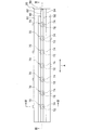
- FIG. 2 is a top view of the lower mold 20 of the mold 10.
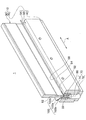
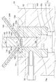
- the lower mold 20 is provided with a mounting portion 50 fixed to the pedestal portion 40, a lower movable portion 60, and a gas spring 70 as a reaction force generating member that supports the lower movable portion 60 from below.
- the mounting portion 50 is formed with a concave groove 52 along the longitudinal direction A.
- a receiving member 54 is fitted into the groove 52.
- the receiving member 54 is being fixed to the mounting part 50 with the some volt
- the cross-sectional shape of both end portions 62a and 62a of the facing surface 62 has an arc shape that protrudes upward.
- the curvature radius r3 of the end 62a is set to be smaller than the curvature radius r4 of the edges 20a and 20a of the receiving member 54 (r3 ⁇ r4). If it does in this way, the space part formed by the three members of the edge part 62a of the lower side movable part 60, the edge part 20a of the receiving member 54, and the workpiece
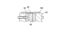
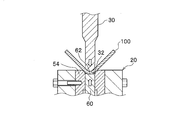
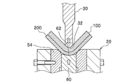
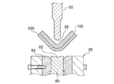
- FIGS. 6A to 6D a processing method using the mold 10 of the first embodiment will be described along each step shown in FIGS. 6A to 6D.
- a process of bending a long flat plate-like workpiece 100 at about 90 degrees in the center in the width direction using the bending machine 1 will be described.
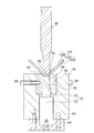
- the upper mold 30 is lowered and the work 100 is pressed.
- the pressing surface 32 of the upper mold 30 presses the workpiece 100 from the upper surface side, and sandwiches the workpiece 100 and the floor plate 200 between the opposing surface 62 of the lower movable portion 60.
- the workpiece 100 is clamped so as not to move outward by the upper mold 30 and the hanging lower movable portion 60.
- bending of the workpiece 100 is started using the R portion of the receiving member 54 as a fulcrum.
- the gas spring 70 moves downward by the pressing force of the upper die.
- the workpiece 100 is bent together with the floor plate 200 while being compressed between the lower mold 20 and the upper mold 30. Processed.
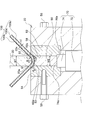
- the workpiece 100 according to the second embodiment is supported from below by a floor plate 200 that abuts uniformly in the in-plane direction from the initial stage of deformation. Therefore, the workpiece 100 is bent while being sandwiched between the upper mold 30 and the floor plate 200 by the reaction force of the gas spring 70.
- the workpiece 100 is strongly embraced by the floor plate 200, the workpiece 100 is not subjected to a tensile pressure, can be bent while applying a compression pressure, and the tension generated on the lower surface side of the workpiece 100 is a surface. It is distributed within and does not concentrate in one place. For this reason, the fracture
- the R portions adjacent to each other above and below the flat portion 120b have curved surfaces having substantially the same arc length.
- the present invention is not limited to this, and the curvature radius r5 and the curvature radius r6 may be different from each other, or may be configured by curved surfaces having different arc lengths. That is, it is not necessary to be symmetric about the flat part 120b, and for example, it may be asymmetric.
- the lower movable portion 160 is also lowered, and the floor plate 200 is more bent than the inflection portions 120c and 120c. It abuts linearly on part of the outer curved surface (curvature radius r5). Thereby, the workpiece 100 starts secondary deformation.
- the floor plate 200 laid on the lower surface of the workpiece 100 is deformed while being in sliding contact with the inflection portions 120c and 120c.
- the workpiece 100 is deformed together with the floor plate 200, since the floor plate 200 is arranged on the bending outer side where the tensile force is large, the workpiece 100 is unlikely to be cracked.
Landscapes
- Engineering & Computer Science (AREA)
- Mechanical Engineering (AREA)
- Bending Of Plates, Rods, And Pipes (AREA)
- Presses And Accessory Devices Thereof (AREA)
Abstract
Un moule (10) servant à plier une pièce à travailler en forme de plaque (100) pourvu : d'un moule inférieur (20) pour placer la pièce à travailler (100) ; d'un moule supérieur (30) sur lequel une surface de pression (32) est formée pour presser la pièce à travailler (100) par déplacement vers le moule inférieur (20) ; une partie mobile inférieure (60) qui est disposée dans le moule inférieur (20) et qui peut coulisser dans la même direction que la direction de déplacement du moule supérieur (30) ; et un ressort à gaz (70) servant à supporter élastiquement la partie mobile inférieure (60) par le dessous. De plus, la surface de pression (32) du moule supérieur (30) est déplacée et vient en contact avec la surface supérieure de la pièce à travailler (100), pressant ainsi la pièce à travailler (100) vers le moule inférieur (20). La partie mobile inférieure (60), supportée élastiquement par le dessous par le ressort à gaz (70), amène une surface opposée (62) en contact avec la surface inférieure de la pièce à travailler (100), et rapproche le moule supérieur (30) du moule inférieur (20) tout en appliquant une force vers le haut opposée à la direction vers le bas qui est la direction de déplacement du moule supérieur (30).
Priority Applications (3)
| Application Number | Priority Date | Filing Date | Title |
|---|---|---|---|
| US16/481,953 US11278945B2 (en) | 2017-01-31 | 2018-01-31 | Die set and working method using the die set |
| CN201880009154.3A CN110234445B (zh) | 2017-01-31 | 2018-01-31 | 模具和使用该模具的加工方法 |
| JP2018565623A JP6761054B2 (ja) | 2017-01-31 | 2018-01-31 | 金型および該金型を用いた加工方法 |
Applications Claiming Priority (2)
| Application Number | Priority Date | Filing Date | Title |
|---|---|---|---|
| JP2017-016251 | 2017-01-31 | ||
| JP2017016251 | 2017-01-31 |
Publications (1)
| Publication Number | Publication Date |
|---|---|
| WO2018143302A1 true WO2018143302A1 (fr) | 2018-08-09 |
Family
ID=63040761
Family Applications (1)
| Application Number | Title | Priority Date | Filing Date |
|---|---|---|---|
| PCT/JP2018/003295 Ceased WO2018143302A1 (fr) | 2017-01-31 | 2018-01-31 | Moule et procédé de traitement utilisant un moule |
Country Status (4)
| Country | Link |
|---|---|
| US (1) | US11278945B2 (fr) |
| JP (1) | JP6761054B2 (fr) |
| CN (1) | CN110234445B (fr) |
| WO (1) | WO2018143302A1 (fr) |
Cited By (5)
| Publication number | Priority date | Publication date | Assignee | Title |
|---|---|---|---|---|
| JPWO2020262684A1 (fr) * | 2019-06-28 | 2020-12-30 | ||
| EP3778062A1 (fr) * | 2019-01-15 | 2021-02-17 | Deharde Gmbh | Procédé de changement de forme d'une pièce en forme de plaque |
| CN112605266A (zh) * | 2020-12-04 | 2021-04-06 | 成都宏明双新科技股份有限公司 | 一种带料上叶片圈圆的模具 |
| WO2021187499A1 (fr) * | 2020-03-16 | 2021-09-23 | 日軽金アクト株式会社 | Matrice et procédé de traitement utilisant une matrice |
| CN114713717A (zh) * | 2022-04-08 | 2022-07-08 | 荣成歌尔科技有限公司 | 冲压模具和工件加工方法 |
Families Citing this family (9)
| Publication number | Priority date | Publication date | Assignee | Title |
|---|---|---|---|---|
| US11803849B1 (en) * | 2020-07-30 | 2023-10-31 | Mark Lawrence | Method and apparatus for decentralized micro businesses |
| CN113000644B (zh) * | 2021-03-01 | 2022-10-21 | 南通市达欣工程股份有限公司 | 建材加工设备 |
| CN113351697B (zh) * | 2021-05-08 | 2022-08-30 | 广东正奇精密模具有限公司 | 一种钣金弯曲模具 |
| CN114918305B (zh) * | 2022-04-18 | 2024-12-17 | 上海科正模具有限公司 | 一种防褶皱铝板柴油机保护罩冷冲压成型模具 |
| CN114951367A (zh) * | 2022-06-29 | 2022-08-30 | 中航西安飞机工业集团股份有限公司 | 一种invar钢基体复材成型工装型板成型模具 |
| CN115090768A (zh) * | 2022-06-29 | 2022-09-23 | 中航西安飞机工业集团股份有限公司 | 一种正压与侧压两向驱动的琴形件成形模具和成形方法 |
| CN115313122B (zh) * | 2022-07-21 | 2025-07-04 | 深圳市鑫锦鸿电子科技有限公司 | 一种天线连接线及其生产设备 |
| CN115090723A (zh) * | 2022-08-26 | 2022-09-23 | 泰州市新龙翔金属制品有限公司 | 一种角钢折角装置 |
| AT527446A1 (de) * | 2023-07-18 | 2025-02-15 | Trumpf Maschinen Austria Gmbh & Co Kg | Biegegesenk für eine Biegemaschine und Verfahren zur Herstellung eines Biegegesenks |
Citations (5)
| Publication number | Priority date | Publication date | Assignee | Title |
|---|---|---|---|---|
| JPS502923U (fr) * | 1973-05-11 | 1975-01-13 | ||
| JPH0994615A (ja) * | 1995-07-27 | 1997-04-08 | Nico Tec:Kk | 金 型 |
| JPH09295052A (ja) * | 1996-05-10 | 1997-11-18 | Amada Metrecs Co Ltd | プレスブレーキ用ダイ |
| JP2007105743A (ja) * | 2005-10-11 | 2007-04-26 | Amada Co Ltd | ダイ金型,折曲げ加工方法及び装置 |
| JP2014108444A (ja) * | 2012-12-03 | 2014-06-12 | Shiroki Corp | 長尺部材の製造方法及び長尺部材製造装置 |
Family Cites Families (15)
| Publication number | Priority date | Publication date | Assignee | Title |
|---|---|---|---|---|
| US3566661A (en) * | 1968-07-29 | 1971-03-02 | Budd Co | Metal forming |
| US3613427A (en) * | 1969-04-28 | 1971-10-19 | Aluminum Co Of America | Forming die structure |
| JPS502923A (fr) | 1973-05-09 | 1975-01-13 | ||
| DE2757658C2 (de) * | 1977-12-23 | 1983-12-29 | Hermann Müller GmbH, 4630 Bochum | Vorrichtung zum Herstellen von zu Rohrkrümmern zusammenschweißbaren gleichgeformten Halbschalen durch Verformung ebener Blechplatinen |
| JPS60154823A (ja) * | 1984-01-25 | 1985-08-14 | Nissan Motor Co Ltd | プレス成形方法とその装置 |
| JP2812201B2 (ja) | 1994-07-15 | 1998-10-22 | トヨタ自動車株式会社 | プレス装置 |
| US6260402B1 (en) * | 1999-03-10 | 2001-07-17 | Simpson Strong-Tie Company, Inc. | Method for forming a short-radius bend in flanged sheet metal member |
| US7401491B2 (en) * | 2005-09-09 | 2008-07-22 | David Leland | Brake die inserts |
| CN101569907A (zh) * | 2008-04-28 | 2009-11-04 | 鸿富锦精密工业(深圳)有限公司 | 折弯模具 |
| JP5375941B2 (ja) * | 2011-12-21 | 2013-12-25 | Jfeスチール株式会社 | プレス成形用金型設計方法、プレス成形用金型 |
| CN202877347U (zh) * | 2012-08-31 | 2013-04-17 | 滁州凯旋模具制造有限公司 | 固板座折弯模 |
| CN202910172U (zh) * | 2012-10-27 | 2013-05-01 | 安徽多达皖晶新能源有限公司 | 一种加工外筒对合搭接口处的折弯机专用模具结构 |
| US9539636B2 (en) * | 2013-03-15 | 2017-01-10 | Ati Properties Llc | Articles, systems, and methods for forging alloys |
| KR101869177B1 (ko) * | 2013-12-26 | 2018-06-19 | 신닛테츠스미킨 카부시키카이샤 | 모자형 단면 부품의 제조 방법 |
| CN105478588A (zh) * | 2015-11-03 | 2016-04-13 | 吴中区光福良盛机械厂 | 一种防工件磨损的中铰链垫片弯曲模 |
-
2018
- 2018-01-31 JP JP2018565623A patent/JP6761054B2/ja active Active
- 2018-01-31 CN CN201880009154.3A patent/CN110234445B/zh active Active
- 2018-01-31 US US16/481,953 patent/US11278945B2/en active Active
- 2018-01-31 WO PCT/JP2018/003295 patent/WO2018143302A1/fr not_active Ceased
Patent Citations (5)
| Publication number | Priority date | Publication date | Assignee | Title |
|---|---|---|---|---|
| JPS502923U (fr) * | 1973-05-11 | 1975-01-13 | ||
| JPH0994615A (ja) * | 1995-07-27 | 1997-04-08 | Nico Tec:Kk | 金 型 |
| JPH09295052A (ja) * | 1996-05-10 | 1997-11-18 | Amada Metrecs Co Ltd | プレスブレーキ用ダイ |
| JP2007105743A (ja) * | 2005-10-11 | 2007-04-26 | Amada Co Ltd | ダイ金型,折曲げ加工方法及び装置 |
| JP2014108444A (ja) * | 2012-12-03 | 2014-06-12 | Shiroki Corp | 長尺部材の製造方法及び長尺部材製造装置 |
Cited By (12)
| Publication number | Priority date | Publication date | Assignee | Title |
|---|---|---|---|---|
| EP3778062A1 (fr) * | 2019-01-15 | 2021-02-17 | Deharde Gmbh | Procédé de changement de forme d'une pièce en forme de plaque |
| JPWO2020262684A1 (fr) * | 2019-06-28 | 2020-12-30 | ||
| WO2020262684A1 (fr) * | 2019-06-28 | 2020-12-30 | 川崎重工業株式会社 | Frein à presse et procédé pour actionner un frein à presse |
| JP7169447B2 (ja) | 2019-06-28 | 2022-11-10 | 川崎重工業株式会社 | プレスブレーキおよびプレスブレーキの運転方法 |
| US12076776B2 (en) | 2019-06-28 | 2024-09-03 | Kawasaki Jukogyo Kabushiki Kaisha | Press brake and method of operating press brake |
| WO2021187499A1 (fr) * | 2020-03-16 | 2021-09-23 | 日軽金アクト株式会社 | Matrice et procédé de traitement utilisant une matrice |
| JPWO2021187499A1 (fr) * | 2020-03-16 | 2021-09-23 | ||
| US20220402010A1 (en) * | 2020-03-16 | 2022-12-22 | Nikkeikin Aluminium Core Technology Company, Ltd. | Die set and processing method using die set |
| JP7276758B2 (ja) | 2020-03-16 | 2023-05-18 | 日軽金アクト株式会社 | 金型および金型を用いた加工方法 |
| CN112605266A (zh) * | 2020-12-04 | 2021-04-06 | 成都宏明双新科技股份有限公司 | 一种带料上叶片圈圆的模具 |
| CN114713717A (zh) * | 2022-04-08 | 2022-07-08 | 荣成歌尔科技有限公司 | 冲压模具和工件加工方法 |
| CN114713717B (zh) * | 2022-04-08 | 2023-12-29 | 荣成歌尔科技有限公司 | 冲压模具和工件加工方法 |
Also Published As
| Publication number | Publication date |
|---|---|
| US20200038932A1 (en) | 2020-02-06 |
| JP6761054B2 (ja) | 2020-09-23 |
| JPWO2018143302A1 (ja) | 2019-11-07 |
| CN110234445A (zh) | 2019-09-13 |
| US11278945B2 (en) | 2022-03-22 |
| CN110234445B (zh) | 2021-06-15 |
Similar Documents
| Publication | Publication Date | Title |
|---|---|---|
| WO2018143302A1 (fr) | Moule et procédé de traitement utilisant un moule | |
| CN105792957B (zh) | 压制成型装置、使用了该成型装置的压制成型品的制造方法以及压制成型品 | |
| KR100236867B1 (ko) | 신장 제어식 성형 기구와 금속 블랭크 성형 방법 | |
| JP4781380B2 (ja) | プレス加工装置及びプレス加工方法 | |
| JP2015027698A (ja) | プレス成形方法及び装置 | |
| US11135634B2 (en) | Press forming device and method for producing press-formed articles | |
| JP7276758B2 (ja) | 金型および金型を用いた加工方法 | |
| US10226807B2 (en) | Press forming method and method of manufacturing pressed product as well as press forming apparatus | |
| KR102446094B1 (ko) | 상부 패드와 하부 펀치를 가공하여 내부지지 방식으로 측방향 하중을 지지하는 벤딩 프레스금형 | |
| WO2011115244A1 (fr) | Procédé de moulage de pièce en forme de plaque, et article moulé | |
| US10413956B2 (en) | Press forming method and method of manufacturing press formed product | |
| GB2475954A (en) | Stretch forming device and method for stretch forming a workpiece | |
| US11498108B2 (en) | Manufacturing apparatus and manufacturing method for hat-shaped cross-section component | |
| JP2011110557A (ja) | ワーク位置決め装置 | |
| JP3854525B2 (ja) | プレス成形方法および成形装置 | |
| JP2006255770A (ja) | 金属板の曲げ加工装置および曲げ加工方法 | |
| US11498110B2 (en) | Fine blanking method and device for forming friction plates with friction material layers | |
| WO2016088519A1 (fr) | Procédé de formage à la presse et procédé de fabrication d'un composant utilisant le même procédé et dispositif de formage à la presse et composant formé à la presse qui est formé à la presse à l'aide du même dispositif | |
| WO2015152142A1 (fr) | Moule pour presse-plieuse et procédé de rabattage | |
| US11850647B2 (en) | Press form device and method for producing press-formed articles | |
| US3908435A (en) | Edge bending press | |
| KR20130120352A (ko) | 금속소재 절단장치 | |
| JPH05131220A (ja) | 複合金属板の曲げ加工方法 | |
| JP2924701B2 (ja) | プレス機械のしわ押え方法およびしわ押え装置 | |
| JP2017144449A (ja) | 相当ひずみ付与装置 |
Legal Events
| Date | Code | Title | Description |
|---|---|---|---|
| 121 | Ep: the epo has been informed by wipo that ep was designated in this application |
Ref document number: 18748790 Country of ref document: EP Kind code of ref document: A1 |
|
| ENP | Entry into the national phase |
Ref document number: 2018565623 Country of ref document: JP Kind code of ref document: A |
|
| NENP | Non-entry into the national phase |
Ref country code: DE |
|
| 122 | Ep: pct application non-entry in european phase |
Ref document number: 18748790 Country of ref document: EP Kind code of ref document: A1 |