WO2018154703A1 - Système de diagnostic d'anomalies - Google Patents
Système de diagnostic d'anomalies Download PDFInfo
- Publication number
- WO2018154703A1 WO2018154703A1 PCT/JP2017/007080 JP2017007080W WO2018154703A1 WO 2018154703 A1 WO2018154703 A1 WO 2018154703A1 JP 2017007080 W JP2017007080 W JP 2017007080W WO 2018154703 A1 WO2018154703 A1 WO 2018154703A1
- Authority
- WO
- WIPO (PCT)
- Prior art keywords
- processing
- diagnosis
- diagnostic
- unit
- processing unit
- Prior art date
- Legal status (The legal status is an assumption and is not a legal conclusion. Google has not performed a legal analysis and makes no representation as to the accuracy of the status listed.)
- Ceased
Links
Images

Classifications
-
- G—PHYSICS
- G06—COMPUTING OR CALCULATING; COUNTING
- G06F—ELECTRIC DIGITAL DATA PROCESSING
- G06F11/00—Error detection; Error correction; Monitoring
- G06F11/22—Detection or location of defective computer hardware by testing during standby operation or during idle time, e.g. start-up testing
- G06F11/25—Testing of logic operation, e.g. by logic analysers
-
- G—PHYSICS
- G06—COMPUTING OR CALCULATING; COUNTING
- G06F—ELECTRIC DIGITAL DATA PROCESSING
- G06F11/00—Error detection; Error correction; Monitoring
- G06F11/22—Detection or location of defective computer hardware by testing during standby operation or during idle time, e.g. start-up testing
- G06F11/26—Functional testing
- G06F11/273—Tester hardware, i.e. output processing circuits
-
- G—PHYSICS
- G05—CONTROLLING; REGULATING
- G05B—CONTROL OR REGULATING SYSTEMS IN GENERAL; FUNCTIONAL ELEMENTS OF SUCH SYSTEMS; MONITORING OR TESTING ARRANGEMENTS FOR SUCH SYSTEMS OR ELEMENTS
- G05B23/00—Testing or monitoring of control systems or parts thereof
- G05B23/02—Electric testing or monitoring
-
- G—PHYSICS
- G06—COMPUTING OR CALCULATING; COUNTING
- G06F—ELECTRIC DIGITAL DATA PROCESSING
- G06F16/00—Information retrieval; Database structures therefor; File system structures therefor
- G06F16/20—Information retrieval; Database structures therefor; File system structures therefor of structured data, e.g. relational data
- G06F16/24—Querying
- G06F16/245—Query processing
-
- G—PHYSICS
- G05—CONTROLLING; REGULATING
- G05B—CONTROL OR REGULATING SYSTEMS IN GENERAL; FUNCTIONAL ELEMENTS OF SUCH SYSTEMS; MONITORING OR TESTING ARRANGEMENTS FOR SUCH SYSTEMS OR ELEMENTS
- G05B23/00—Testing or monitoring of control systems or parts thereof
- G05B23/02—Electric testing or monitoring
- G05B23/0205—Electric testing or monitoring by means of a monitoring system capable of detecting and responding to faults
- G05B23/0259—Electric testing or monitoring by means of a monitoring system capable of detecting and responding to faults characterized by the response to fault detection
- G05B23/0286—Modifications to the monitored process, e.g. stopping operation or adapting control
- G05B23/0294—Optimizing process, e.g. process efficiency, product quality
-
- G—PHYSICS
- G06—COMPUTING OR CALCULATING; COUNTING
- G06F—ELECTRIC DIGITAL DATA PROCESSING
- G06F11/00—Error detection; Error correction; Monitoring
- G06F11/30—Monitoring
- G06F11/3089—Monitoring arrangements determined by the means or processing involved in sensing the monitored data, e.g. interfaces, connectors, sensors, probes, agents
-
- G—PHYSICS
- G06—COMPUTING OR CALCULATING; COUNTING
- G06F—ELECTRIC DIGITAL DATA PROCESSING
- G06F11/00—Error detection; Error correction; Monitoring
- G06F11/30—Monitoring
- G06F11/34—Recording or statistical evaluation of computer activity, e.g. of down time, of input/output operation ; Recording or statistical evaluation of user activity, e.g. usability assessment
- G06F11/3452—Performance evaluation by statistical analysis
Definitions
- the present invention relates to an abnormality diagnosis system and an abnormality diagnosis method for an apparatus having a drive part.
- an abnormality sign diagnosis apparatus is a sensor data acquisition unit that acquires multidimensional sensor data measured by a plurality of sensors installed in a machine facility;
- a data mining unit that diagnoses the presence or absence of an abnormal sign based on the degree of abnormality indicating the degree of deviation from the normal model generated by learning using sensor data when the sensor is operating normally, and individual sensor data
- a remote monitoring unit for diagnosing the presence or absence of an abnormality sign based on whether or not the value is within a predetermined range, and the data mining unit is in accordance with an instruction from the initialization instruction means.
- Patent Document 1 describes a method of diagnosing a sign of abnormality of a mechanical facility based on the degree of deviation from a normal model. It also describes how to reconstruct a normal model in response to changes in the external environment.
- this diagnostic device is fixed, and when the diagnostic target or diagnostic sensor is changed, it is necessary to recreate the diagnostic device for a new diagnostic target or diagnostic sensor.
- the abnormality diagnosis system of the present invention detects a failure sign of a diagnosis target device, compares a plurality of diagnosis processing procedures, searches for a suitable diagnosis processing procedure, and
- the diagnostic processing includes a diagnostic processing search unit that outputs reconfiguration information corresponding to a suitable diagnostic processing procedure, and a reconfigurable processing unit, and reconfigures the processing unit based on the reconfiguration information. And a diagnostic processing unit that detects a failure sign of the diagnosis target device using the preferable diagnostic processing procedure searched by the search unit.
- the diagnostic processing unit can be easily reconfigured, even if the diagnostic target device or the diagnostic target item is changed, the failure in the diagnostic processing procedure suitable for the changed diagnostic target etc. Predictive detection can be realized easily and quickly.
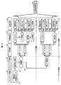
- Configuration diagram of an abnormality diagnosis system of one embodiment Processing flow of abnormality diagnosis system of one embodiment Reconfigurable circuit overview Processing contents in each processing of FIG. Examples of prepared diagnostic procedures Example of optimal diagnostic processing procedure selected from the diagnostic processing procedure of FIG.
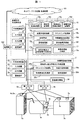
- FIG. 1 is a configuration diagram of an abnormality diagnosis system 100 according to an embodiment.
- This abnormality diagnosis system 100 is used to detect a sign of failure of a diagnosis target device.
- an optimum diagnosis processing search unit 1 (“diagnosis processing search unit” that searches for an optimal diagnosis processing procedure is used. ”)
- An actual operation diagnosis processing unit 2 also referred to as“ diagnosis processing unit ” used to actually detect a sign of failure of the diagnosis target device, a storage / processing device 101 on the network, and And a communication path 102 to be connected.
- diagnosis processing unit also referred to as“ diagnosis processing unit ” used to actually detect a sign of failure of the diagnosis target device
- a storage / processing device 101 on the network and And a communication path 102 to be connected.
- the following description is based on the assumption that the system includes the storage / processing device 101 on the network. However, the system may be omitted.
- the expression “optimum diagnosis process” used below does not mean “optimum diagnosis process” in consideration of all conditions, but refers to
- the diagnosis target of the abnormality diagnosis system 100 is an air compressor 3 including a power source 3a, a rotating machine 3b, and an air compressor body 3c.
- the power source 3a is provided with current sensors 4a and 5a for measuring a current at a certain part
- the rotating machine 3b is provided with acceleration sensors 4b and 5b
- the air compressor body 3c is provided with acceleration sensors 4c and 5c. It has been.
- sensor data obtained by the current sensor 4a and the acceleration sensors 4b and 4c will be referred to as first sensor data 6a
- sensor data obtained by the current sensor 5a and the acceleration sensors 5b and 5c will be referred to as second sensor data 6b. Called.
- the first sensor data 6 a is input to the optimum diagnosis processing search unit 1
- the second sensor data 6 b is input to the actual operation diagnosis processing unit 2.
- the acceleration sensor is configured to be separately provided for the optimum diagnosis processing search unit 1 and the actual operation diagnosis processing unit 2 separately, and the current sensor is configured to share one sensor.
- the application target is not limited to this configuration.
- the sensor (4a, 4b, 4c) dedicated to the optimum diagnosis processing search unit 1 is provided with a detection band and a measurement range, as in the acceleration sensor of FIG. Both are wide but expensive sensors, and the sensors (5a, 5b, 5c) dedicated to the actual operation diagnosis processing unit 2 are preferably inexpensive sensors with a narrow detection band and measurement range. If the bandwidth and measurement range necessary for abnormality diagnosis can be specified using the sensor dedicated to the optimum diagnosis processing search unit 1, by selecting an inexpensive sensor dedicated to the actual operation diagnosis processing unit 2 that satisfies the range, This is because an appropriate abnormality diagnosis in the actual operation diagnosis processing unit 2 can be realized at a low cost.
- the optimum diagnosis processing search unit 1 and the actual operation diagnosis processing unit 2 share one sensor as in the current sensor of FIG. It is only necessary to use an inexpensive sensor with a narrow range.
- the optimum diagnosis process search unit 1 is a part for searching for an optimum diagnosis process procedure and algorithm. As shown in FIG. 1, the central controller 11, the input device 12, the output device 13, the communication device 14, and the signal processing group memory are stored. Unit 15, signal processing execution unit 16, and actual operation processing reconfiguration unit 17. These may be realized using a personal computer or the like, or may be manufactured as a dedicated machine. Further, as will be described later, a part or the whole may be configured by using an electronic circuit or a CPU capable of reconfiguring processing procedures and algorithms.
- the actual operation diagnosis processing unit 2 is a processing unit that realizes the whole or a part by using an electronic circuit or a CPU that can reconfigure the optimum processing procedure and algorithm searched by the optimum diagnosis processing searching unit 1.
- the control unit 21 includes an input device 22, an output device 23, a communication device 24, a reconfigurable circuit and processing device 25, and a device specification information database 26.
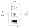
- the reconfigurable circuit and processing device 25 processes the sensor data 30 obtained from the sensors for the actual operation diagnosis processing unit 2 such as the current sensor 5a, the acceleration sensors 5b, 5c, and the diagnosis result. 34, and is composed of a reconfigurable analog circuit 31, a reconfigurable digital circuit 32, and a programmable CPU 33. These can be connected in any order.
- the sensor data 30 is first processed by the reconfigurable analog circuit 31 and the output of the reconfigurable analog circuit 31 is processed by the reconfigurable digital circuit 32. Then, the output of the reconfigurable digital circuit 32 is processed by the programmable CPU 33 so that the diagnosis result 34 can be obtained.
- the reconfigurable analog circuit 31 is a circuit that can be reconfigured into an analog circuit having various functions by switching circuit connections of internal operational amplifiers, resistors, capacitors, and the like with a switch circuit, and is also called Programmable System-on-Chip. It is said. By changing the internal circuit connection of the reconfigurable analog circuit 31, analog signal processing such as filtering processing, average value / effective value processing of analog sensor data in the analog region can be appropriately realized.
- reconfigurable digital circuit 32 An example of the reconfigurable digital circuit 32 is an FPGA (field-programmable gate array). Even in the reconfigurable digital circuit 32, various digital signal processing can be realized by reconfiguring the internal logic circuit.
- FPGA field-programmable gate array
- the apparatus specification information database 26 of the actual operation diagnosis processing unit 2 shown in FIG. 1 is the specification information of the actual operation diagnosis processing unit 2 itself and the connected sensors (current sensor 5a, acceleration sensors 5b, 5c). Is recorded, and is used when the optimum diagnosis processing search unit 1 creates reconfiguration command information or when selecting a sensor to be connected to the actual operation diagnosis processing unit 2.
- the device specification information database 26 does not necessarily need to be placed in the actual operation diagnosis processing unit 2, and may be placed in the optimum diagnosis processing search unit 1, or may be placed in the network storage / processing device 101 or sensor.
- the specifications may be stored in the sensor confidence.
- the optimum diagnosis processing search unit 1 includes a signal processing group storage unit 15 in which various signal processing methods are stored, a signal processing execution unit 16 that executes various signal processing, and an actual operation diagnostic processing unit. 2 is configured by an actual operation processing reconfiguration unit 17 for creating reconfiguration information for 2.
- the signal processing group storage unit 15 includes a front-end processing storage unit 15a, a preprocessing storage unit 15b, a feature amount extraction processing storage unit 15c, a diagnostic processing storage unit 15d, and the like, and stores processing algorithms in each processing block. Has been. In consideration of the analog / digital mixed processing in the actual operation diagnosis processing unit 2, each processing block prepares a processing block that can be executed in each of the analog area (including simulation) and the digital area.
- the signal processing execution unit 16 is a part that executes the processing algorithm stored in the signal processing group storage unit 15, and specifically includes a processing procedure control unit 16a, a front end processing unit 16b, a preprocessing unit 16c, and a feature. It consists of a quantity extraction processing unit 16d, a diagnostic processing unit 16e, and a diagnostic result evaluation unit 16f.
- the actual operation processing reconfiguration unit 17 includes a processing procedure and diagnosis result storage database 17a, and a reconfiguration information creation unit 17b.
- a plurality of execution results of the signal processing execution unit 16 are stored in the processing procedure and diagnosis result storage database 17a.
- the reconfiguration information creation unit 17 b generates reconfiguration information for the actual operation diagnosis processing unit 2.
- the diagnosis result evaluation unit 16f selects the one evaluated as the optimum diagnosis processing procedure, and the reconstruction information creation unit 17b performs the actual operation diagnosis processing unit. 2 reconstruction information is generated.
- the actual operation diagnosis processing unit 2 includes a reconfigurable circuit and a reconfigurable analog circuit 31, a reconfigurable digital circuit 32, and a programmable CPU 33 in the processing device 25. Reconfigure.
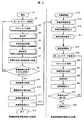
- the optimum diagnosis process search unit 1 When the optimum diagnosis process search is started (S1), the optimum diagnosis process search unit 1 is first processed (S2 to S13), and then the actual operation diagnosis process unit 2 is performed (S14 to S25). .
- the optimal diagnosis process search unit 1 first acquires the first sensor data 6a (S2). For the input value, the front end process S3, the preprocess S4, the feature amount extraction process S5, and the diagnosis process S6 are performed in this order. Processing by a plurality of processing algorithms is performed for each block.
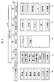
- FIG. 4 shows details of the processing contents of the optimum diagnosis processing search unit 1 performed in S2 to S6.
- Each processing algorithm is stored in the signal processing group storage unit 15.
- the first sensor data 6a is acquired. As illustrated in process block 40, this corresponds to data acquisition from various types of sensors. For example, sensors that change the amount of charge according to the magnitude of acceleration, sensors that change the electromotive force, such as thermocouples, analog output sensors that change the current value, voltage value, resistance value, etc. There are various types of sensors such as a sensor that performs A / D conversion and outputs a digital value, and a digital output sensor that outputs a pulse length.
- the front-end process S3 converts the first sensor data 6a to a voltage value that can be processed uniformly in the analog area when the first sensor data 6a is an analog output.
- a digital output expressed in terms of length or the like
- the digital value is collected.
- a processing module may be created for each conversion process, and an evaluator may remove and insert them as necessary to realize an optimal conversion process, as illustrated in FIG.
- a desired circuit may be reconfigured using a reconfigurable analog circuit or digital circuit.
- the preprocessing S4 is a portion that performs filtering processing and cleansing processing on the data collected in the front end processing S3, and performs preprocessing that removes signal components and data values that are not necessary for signal processing. .
- Feature amount extraction processing S5 is processing for extracting feature amounts effective for device abnormality detection.
- effective value processing, average value processing, spectrum intensity, phase, and the like are prepared as illustrated in the processing block 43, but may be converted into feature amounts using other feature amount conversion algorithms. .
- the diagnosis process S6 performs an abnormality diagnosis process based on the feature quantity necessary for the diagnosis extracted in the feature quantity extraction process S5.
- threshold processing, trend analysis, statistical analysis, a method using AI, and a method using machine learning are prepared as specific methods for abnormality diagnosis.
- Diagnosis processing may be performed using the diagnosis algorithm.
- a / D conversion processing is prepared for the processing blocks 41, 43, and 44. This is because the processing after the front end processing S3, the feature amount extraction processing S5, and the diagnosis processing S6 can be transferred from the analog signal processing area to the digital signal processing area. For example, when A / D conversion is performed at the end of the feature amount extraction processing S5, analog processing is performed up to the feature amount conversion processing S5, and digital processing is performed after the diagnosis processing S6. In the diagnosis processing S6, signals from the FPGA and the CPU Processing techniques can be used.
- processing result visualization 45 may be performed for each processing.
- the visualization 45 of the processing result can be realized by creating drawing data based on the processing result and displaying it on the output device 13 included in the optimum diagnosis processing searching unit 1.
- the charge amount of the charge output type acceleration sensor 50 is acquired in the sensor data acquisition process S2, and the conversion process 51 from the charge amount to the voltage value is performed in the front-end process S3.
- amplification is performed using the amplifier 52 (amplification value parameters and the like are also selection items of a diagnostic result evaluation unit described later).
- preprocessing S4 and feature amount extraction S5 are performed in the analog domain, and the processing block on the upper side in FIG. 5 and the processing block on the lower side in FIG. it can.
- the processing items after the preprocessing S4 are the same in both the analog and digital signal processing areas, and therefore, the overlapping description will be omitted as appropriate.
- first filter and second filter two types of filters (first filter and second filter) are prepared, and these can be selected and used.
- the filter used here is a well-known technique, detailed description is abbreviate
- the feature amount extraction processing S5 includes feature amount extraction from spectrum analysis (FFT in the case of digital signal processing, and a large number of BPFs in the case of analog and output of each effective value), and features from the effective value of the input waveform. Quantity extraction is available, and these can be selected and used.
- Diagnostic processing S6 includes diagnostic algorithms such as the illustrated threshold processing and trend analysis for evaluating the feature amount extracted in the feature amount extraction processing S5, and these can be selected and used.
- the diagnosis process procedure executed by the optimum diagnosis process search unit 1 may be set by the process procedure control unit 16a of the optimum diagnosis process search unit 1, or a specific combination of diagnosis process procedures is manually set by the creator. Things can be used.
- the diagnosis processing procedure may be set comprehensively for all combinations.
- the creator interactively selects a desired diagnostic processing procedure using a screen image editor displayed on the output device 13 such as a liquid crystal display, or a diagnostic processing procedure produced in the past. May be displayed so that it can be reused as it is, or a part of it can be modified and used.
- the process contents that can be selected in each process are limited, or advice is displayed. You may do it.
- the new process content may be additionally stored in the signal processing group storage unit 15 via the input device 12 or the communication device 14.
- each processing block For example, when a plurality of processing contents are registered in each processing so that the processing 51 and 52 of the front-end processing S22 are handled as one continuous processing, a plurality of processing contents are registered. These processing contents may be handled as a series of processing. Furthermore, after the feature amount extraction process S5, a process procedure for returning from the right side to the left side in FIG.
- the processing procedure and the diagnostic processing result obtained through the processing of S2 to S6 are stored in the processing procedure and diagnostic result storage database 17a in association with each other (S7).
- the diagnosis process is continued until an abnormality of the device occurs in the operating environment, or the diagnosis process is continued until the diagnosis result can be evaluated by processing the device and creating an abnormal state intentionally.
- the diagnosis results stored in the database are sufficiently accumulated to be evaluated (S8)
- the diagnosis results are evaluated (S9).
- the evaluation result values at normal time and abnormal time are compared, and the processing procedure with the largest difference or the processing procedure with few disturbance components such as noise is selected automatically or manually.
- the result of each processing procedure is displayed using the output device 13, and an instruction such as selection can be realized by using the input device 12.
- the optimum process procedure is selected from the candidates for the diagnostic process procedure shown in FIG.
- An example of the optimum processing procedure is shown in FIG.
- a diagnosis processing procedure is selected in which the front end processing S3 to the feature amount extraction processing S5 are processed in the analog domain and the diagnostic processing S6 is processed in the digital domain. Yes.
- the reconfiguration information creation process (S11) converts the selected optimal processing procedure into reconfiguration information for reconfiguration on the actual operation diagnosis processing unit 2.
- these processing are converted 64 into reconfiguration information for the reconfigurable analog circuit 31.
- the trend analysis process 63 is performed in the digital domain, this process is converted into a programmable trend analysis algorithm for the CPU 33.
- the trend analysis may be performed by the reconfigurable digital circuit 32. In this case, the trend analysis process 63 can be reconfigured. Convert 64 to reconstructed information for the digital circuit 32.
- the reconfiguration information is output to the actual operation diagnosis processing unit 2 (S12), and the process of the optimum diagnosis process search unit 1 is ended (S13).
- the actual operation diagnosis processing unit 2 performs reconfigurable processing (S14 to S17) of the reconfigurable circuit and processing device 25 prior to the diagnostic processing (S18 to S25).
- the reconfiguration process When the reconfiguration process is started (S14), first, the reconfiguration information output by the optimum diagnosis process search unit 1 is received (S15). Based on the reconfiguration information, the reconfigurable analog circuit 31 and the reconfigurable digital circuit 32 are reconfigured, and the program of the programmable CPU 33 is changed (S16). After these changes are reflected, the actual operation diagnostic processing unit 2 becomes a diagnostic device that performs the same processing procedure as the optimal processing procedure illustrated in FIG. 6 (S17). As a result, when the actual operation diagnosis processing unit 2 starts diagnosis processing during actual operation (S18), the processing from S19 to S23 is executed with the same optimal contents as in FIG. 6, and the diagnosis result is output ( S23).
- the optimum processing procedure searched by the optimum diagnosis processing search unit 1 corresponding to a new sensor, processing algorithm, and diagnosis target is stored in the actual operation diagnosis processing unit 2.
- the reconfigurable circuit and the processing device 25 can be easily reflected.
- the actual operation diagnosis processing unit 2 can be quickly reconfigured to cope with the optimum processing procedure.
- the effect that it can be realized at low cost can be obtained.
- a new diagnostic algorithm is developed, it is possible to easily compare the superiority with the algorithm used so far.
- an abnormality diagnosis system 100 including one optimum diagnosis process search unit 1 and one actual operation diagnosis process unit 2.
- the abnormality diagnosis system 100 is configured by one optimum diagnosis processing search unit 1 and a plurality of actual operation diagnosis processing units 2, and one unit
- the optimum diagnosis process search unit 1 may search for an optimum process and distribute reconfiguration information corresponding to each diagnosis target to a plurality of actual operation diagnosis processing units 2.
- the optimum diagnosis processing search unit 1 and the actual operation diagnosis processing unit 2 are prepared as separate configurations.
- the optimum diagnosis processing search unit 1 is configured by combining both functions in one device. It is good also as a structure which determines an optimal process by making it function as, and makes it function as the real operation diagnostic process part 2 after that.
- the configuration in which the front-end processing S3 to the diagnostic processing S6 are processed by one device has been described.
- the first processing is performed by a device installed in the vicinity of the diagnosis target device, and the second processing is performed on the network. It is good also as a structure performed with an apparatus.
- the optimum diagnostic process search unit 1 performs up to the feature quantity extraction process S5, and the extracted feature quantity extraction data is transmitted to the storage / processing device 101 on the network via the communication path 102, and the network after the diagnostic process S6.
- a configuration may be adopted in which the reconfiguration information generated there is transmitted to the actual operation diagnosis processing unit 2.
- 100 abnormality diagnosis system 101 storage / processing device on network, 102 communication path, 1 optimal diagnosis processing search unit, 11 central control device, 12 input device, 13 output device, 14 communication device, 15 signal processing group storage unit, 15a Front-end processing storage unit, 15b pre-processing storage unit, 15c feature quantity extraction processing storage unit, 15d diagnostic processing storage unit 16, signal processing execution unit, 16a processing procedure control unit, 16b front-end processing unit, 16c pre-processing unit, 16d Volume extraction processing unit, 16e diagnosis processing unit, 16f diagnosis result evaluation unit, 17 actual operation processing reconfiguration unit, 17a processing procedure and diagnosis result storage database, 17b reconfiguration information creation unit, 2 operation diagnosis processing unit, 21 center Control device, 22 input device, 23 output device, 24 communication device, 25 Configurable circuit and processing device, 26 device specification information database, 3 air compressor, 3a power supply, 3b rotating machine, 3c air compressor body, 4a, 5a current sensor, 4b, 4c, 5b, 5c acceleration sensor 6a No. 1 sensor data, 6b 2nd sensor data, 30 sensor data
Landscapes
- Engineering & Computer Science (AREA)
- Theoretical Computer Science (AREA)
- General Engineering & Computer Science (AREA)
- General Physics & Mathematics (AREA)
- Physics & Mathematics (AREA)
- Quality & Reliability (AREA)
- Computer Hardware Design (AREA)
- Databases & Information Systems (AREA)
- Data Mining & Analysis (AREA)
- Computational Linguistics (AREA)
- Automation & Control Theory (AREA)
- Testing And Monitoring For Control Systems (AREA)
- Testing Or Calibration Of Command Recording Devices (AREA)
Abstract
Dans un dispositif de diagnostic classique, le contenu du traitement est fixe et, lorsqu'une cible de diagnostic ou un capteur de diagnostic change, il est nécessaire de recréer un dispositif de diagnostic pour la nouvelle cible de diagnostic ou le nouveau capteur de diagnostic. En outre, lorsque l'on développe un nouvel algorithme de diagnostic, on se retrouve face au problème de l'impossibilité de comparer la supériorité etc. du nouvel algorithme à celle de l'algorithme utilisé jusqu'à présent. La présente invention est donc conçue de la manière suivante. Elle concerne un système de diagnostic d'anomalies qui détecte un signe de défaillance d'un dispositif à diagnostiquer, le système de diagnostic d'anomalies comprenant : une unité de recherche de processus de diagnostic qui recherche une procédure de traitement de diagnostic appropriée en comparant une pluralité de procédures de traitement de diagnostic, et qui fournit des informations de reconfiguration correspondant à la procédure de traitement de diagnostic appropriée ; et une unité de traitement de diagnostic qui possède une unité de traitement reconfigurable et qui utilise la procédure de traitement de diagnostic appropriée déterminée par l'unité de recherche de processus de diagnostic pour détecter un signe de défaillance du dispositif à diagnostiquer par une reconfiguration de l'unité de traitement selon les informations de reconfiguration.
Priority Applications (4)
| Application Number | Priority Date | Filing Date | Title |
|---|---|---|---|
| US16/476,123 US11397655B2 (en) | 2017-02-24 | 2017-02-24 | Abnormality diagnosis system that reconfigures a diagnostic program based on an optimal diagnosis procedure found by comparing a plurality of diagnosis procedures |
| CN201780082562.7A CN110168461B (zh) | 2017-02-24 | 2017-02-24 | 异常诊断系统 |
| JP2019500945A JP6712354B2 (ja) | 2017-02-24 | 2017-02-24 | 異常診断システム |
| PCT/JP2017/007080 WO2018154703A1 (fr) | 2017-02-24 | 2017-02-24 | Système de diagnostic d'anomalies |
Applications Claiming Priority (1)
| Application Number | Priority Date | Filing Date | Title |
|---|---|---|---|
| PCT/JP2017/007080 WO2018154703A1 (fr) | 2017-02-24 | 2017-02-24 | Système de diagnostic d'anomalies |
Publications (1)
| Publication Number | Publication Date |
|---|---|
| WO2018154703A1 true WO2018154703A1 (fr) | 2018-08-30 |
Family
ID=63252508
Family Applications (1)
| Application Number | Title | Priority Date | Filing Date |
|---|---|---|---|
| PCT/JP2017/007080 Ceased WO2018154703A1 (fr) | 2017-02-24 | 2017-02-24 | Système de diagnostic d'anomalies |
Country Status (4)
| Country | Link |
|---|---|
| US (1) | US11397655B2 (fr) |
| JP (1) | JP6712354B2 (fr) |
| CN (1) | CN110168461B (fr) |
| WO (1) | WO2018154703A1 (fr) |
Families Citing this family (2)
| Publication number | Priority date | Publication date | Assignee | Title |
|---|---|---|---|---|
| JP7495874B2 (ja) * | 2020-12-16 | 2024-06-05 | 株式会社日立製作所 | プラント制御システム、プラント制御方法及びプログラム |
| CN118742864A (zh) * | 2022-03-04 | 2024-10-01 | 三菱电机株式会社 | 输入输出装置、脉宽显示系统及脉宽显示方法 |
Citations (2)
| Publication number | Priority date | Publication date | Assignee | Title |
|---|---|---|---|---|
| JP2007257190A (ja) * | 2006-03-22 | 2007-10-04 | Toshiba Corp | 総合監視診断装置 |
| JP2015203936A (ja) * | 2014-04-14 | 2015-11-16 | 株式会社日立製作所 | 状態監視装置 |
Family Cites Families (27)
| Publication number | Priority date | Publication date | Assignee | Title |
|---|---|---|---|---|
| JP3187246B2 (ja) * | 1994-04-21 | 2001-07-11 | 横河電機株式会社 | プラント診断システム |
| US5764954A (en) * | 1995-08-23 | 1998-06-09 | International Business Machines Corporation | Method and system for optimizing a critical path in a field programmable gate array configuration |
| WO1999031574A1 (fr) * | 1997-12-17 | 1999-06-24 | Hewlett-Packard Company | Mise en application de multiplicateurs dans des matrices programmables |
| US6530049B1 (en) * | 2000-07-06 | 2003-03-04 | Lattice Semiconductor Corporation | On-line fault tolerant operation via incremental reconfiguration of field programmable gate arrays |
| EP1390246B1 (fr) * | 2001-05-08 | 2018-08-15 | Siemens Industry, Inc. | Systeme de surveillance d'etat |
| JP4622177B2 (ja) * | 2001-07-06 | 2011-02-02 | 株式会社デンソー | 故障診断システム、車両管理装置、サーバ装置、及び検査診断プログラム |
| US7577726B1 (en) * | 2002-02-07 | 2009-08-18 | Cisco Technology, Inc. | Method for updating a hardware configuration of a networked communications device |
| US20040027118A1 (en) * | 2002-08-12 | 2004-02-12 | James Lenz | Proximity sensor circuit with programmable logic device controller |
| JP3874110B2 (ja) * | 2002-08-30 | 2007-01-31 | 日本精工株式会社 | 異常診断システム |
| JP2005033559A (ja) * | 2003-07-14 | 2005-02-03 | Fuji Xerox Co Ltd | 故障診断装置 |
| WO2006043511A1 (fr) * | 2004-10-18 | 2006-04-27 | Nsk Ltd. | Systeme de diagnostic d’anomalie pour une machinerie |
| US20070211965A1 (en) * | 2006-03-07 | 2007-09-13 | Helbing Rene P | Hand-held diagnostic systems and methods of use thereof |
| EP2144166A4 (fr) * | 2007-03-29 | 2011-01-12 | Nec Corp | Système de diagnostic |
| JP5159242B2 (ja) * | 2007-10-18 | 2013-03-06 | キヤノン株式会社 | 診断支援装置、診断支援装置の制御方法、およびそのプログラム |
| US8301406B2 (en) * | 2008-07-24 | 2012-10-30 | University Of Cincinnati | Methods for prognosing mechanical systems |
| JP5290026B2 (ja) * | 2009-03-31 | 2013-09-18 | 日立建機株式会社 | 作業機械の学習診断システム、状態診断装置及び状態学習装置 |
| US8639474B2 (en) * | 2010-08-31 | 2014-01-28 | Toshiba International Corporation | Microcontroller-based diagnostic module |
| JP5455866B2 (ja) * | 2010-10-28 | 2014-03-26 | 株式会社日立製作所 | 異常診断装置および産業機械 |
| JP5808605B2 (ja) * | 2011-08-17 | 2015-11-10 | 株式会社日立製作所 | 異常検知・診断方法、および異常検知・診断システム |
| US20130297256A1 (en) * | 2012-05-04 | 2013-11-07 | Jun Yang | Method and System for Predictive and Conditional Fault Detection |
| US9892568B2 (en) * | 2012-08-20 | 2018-02-13 | Innova Electronics Corporation | Method and system for determining the likely operating cost for a particular type of vehicle over a defined period |
| WO2014041596A1 (fr) * | 2012-09-11 | 2014-03-20 | 三菱電機株式会社 | Contrôleur de sécurité |
| US9158891B2 (en) * | 2013-02-15 | 2015-10-13 | Cochlear Limited | Medical device diagnostics using a portable device |
| JP6149929B2 (ja) * | 2013-05-10 | 2017-06-21 | 富士通株式会社 | 診断装置、診断方法及びプログラム |
| JP5369246B1 (ja) | 2013-07-10 | 2013-12-18 | 株式会社日立パワーソリューションズ | 異常予兆診断装置及び異常予兆診断方法 |
| US20160323143A1 (en) * | 2015-05-02 | 2016-11-03 | Hyeung-Yun Kim | Method and apparatus for neuroplastic internet of things by cloud computing infrastructure as a service incorporating reconfigurable hardware |
| US10073115B1 (en) * | 2016-04-18 | 2018-09-11 | The United States Of America As Represented By The Administrator Of National Aeronautics And Space Administration | Self diagnostic accelerometer field programmable gate array (SDA FPGA) |
-
2017
- 2017-02-24 WO PCT/JP2017/007080 patent/WO2018154703A1/fr not_active Ceased
- 2017-02-24 JP JP2019500945A patent/JP6712354B2/ja active Active
- 2017-02-24 CN CN201780082562.7A patent/CN110168461B/zh active Active
- 2017-02-24 US US16/476,123 patent/US11397655B2/en active Active
Patent Citations (2)
| Publication number | Priority date | Publication date | Assignee | Title |
|---|---|---|---|---|
| JP2007257190A (ja) * | 2006-03-22 | 2007-10-04 | Toshiba Corp | 総合監視診断装置 |
| JP2015203936A (ja) * | 2014-04-14 | 2015-11-16 | 株式会社日立製作所 | 状態監視装置 |
Also Published As
| Publication number | Publication date |
|---|---|
| CN110168461A (zh) | 2019-08-23 |
| CN110168461B (zh) | 2022-01-11 |
| JP6712354B2 (ja) | 2020-06-17 |
| US11397655B2 (en) | 2022-07-26 |
| JPWO2018154703A1 (ja) | 2019-11-07 |
| US20190354456A1 (en) | 2019-11-21 |
Similar Documents
| Publication | Publication Date | Title |
|---|---|---|
| JP6961424B2 (ja) | 故障診断システム | |
| JP6388102B1 (ja) | 情報端末器及び機械部品診断システム | |
| JP2018119924A (ja) | 診断装置 | |
| US11353860B2 (en) | Data analysis device, system, method, and recording medium storing program | |
| JP6712354B2 (ja) | 異常診断システム | |
| US9400305B2 (en) | Instrument and method for detecting partial electric discharges in an electric apparatus | |
| WO2020162425A1 (fr) | Dispositif d'analyse, procédé d'analyse et programme | |
| US20210018906A1 (en) | Feature Value Extraction Apparatus, Predicted-Failure-Evidence Diagnosis Apparatus, Design Assistance Apparatus, and Predicted-Failure-Evidence Diagnosis Operation Method | |
| Verma et al. | Android app for intelligent CBM | |
| KR102198190B1 (ko) | 운전조건을 고려한 회전체 고장 진단 데이터 정규화 처리 방법 및 이를 이용한 회전체 고장 진단 방법 | |
| KR20240107690A (ko) | 클라우드 기반 운영 장비/부품의 수명고장 예방 및 진단 처방 시스템과 그 방법 | |
| US9779558B2 (en) | Calibration tool assembly and method of using same | |
| JP2004020484A (ja) | 異常監視装置および異常監視プログラム | |
| WO2021256358A1 (fr) | Dispositif de détermination prédictive, système de détermination prédictive, procédé de détermination prédictive et programme | |
| KR102348387B1 (ko) | 회전체 건전성 평가 시스템 및 방법 | |
| KR102837083B1 (ko) | 학습 장치 및 학습 방법, 시간 영역의 진동 신호에 기초하여 설비의 이상 여부를 진단하는 진단 장치 및 고장 진단 방법 | |
| RU2700905C2 (ru) | Адаптивный и управляемый состояниями сбор данных | |
| KR20220092137A (ko) | 시스템 상태 진단 장치 및 방법 | |
| JP4513796B2 (ja) | 異常監視装置 | |
| US20250164985A1 (en) | Monitoring Methods, Computer Program Product, Monitoring Unit, Gas Analysis Device, and use of Artificial Intelligence | |
| JP2025539291A (ja) | 学習装置および学習方法、信号再構成モデルを用いて設備の異常有無を診断する故障診断装置および故障診断方法 | |
| JP2024007269A (ja) | 異常検出装置、監視制御装置、異常検出方法および異常検出プログラム | |
| JPH06331503A (ja) | ダイナモメータの計測処理装置 | |
| JP2021173572A (ja) | 異常診断プログラム、情報処理装置及び異常診断方法 | |
| RO133002A2 (ro) | Vibrochange.ds - sistem pentru detecţia schimbărilor în procese vibratorii, folosind tehnici avansate de analiză bazate pe model |
Legal Events
| Date | Code | Title | Description |
|---|---|---|---|
| 121 | Ep: the epo has been informed by wipo that ep was designated in this application |
Ref document number: 17898317 Country of ref document: EP Kind code of ref document: A1 |
|
| ENP | Entry into the national phase |
Ref document number: 2019500945 Country of ref document: JP Kind code of ref document: A |
|
| NENP | Non-entry into the national phase |
Ref country code: DE |
|
| 122 | Ep: pct application non-entry in european phase |
Ref document number: 17898317 Country of ref document: EP Kind code of ref document: A1 |