WO2018154792A1 - 被覆除去装置 - Google Patents
被覆除去装置 Download PDFInfo
- Publication number
- WO2018154792A1 WO2018154792A1 PCT/JP2017/008491 JP2017008491W WO2018154792A1 WO 2018154792 A1 WO2018154792 A1 WO 2018154792A1 JP 2017008491 W JP2017008491 W JP 2017008491W WO 2018154792 A1 WO2018154792 A1 WO 2018154792A1
- Authority
- WO
- WIPO (PCT)
- Prior art keywords
- unit
- heating
- coating
- gripping
- coating removal
- Prior art date
- Legal status (The legal status is an assumption and is not a legal conclusion. Google has not performed a legal analysis and makes no representation as to the accuracy of the status listed.)
- Ceased
Links
Images






Classifications
-
- G—PHYSICS
- G02—OPTICS
- G02B—OPTICAL ELEMENTS, SYSTEMS OR APPARATUS
- G02B6/00—Light guides; Structural details of arrangements comprising light guides and other optical elements, e.g. couplings
- G02B6/24—Coupling light guides
- G02B6/245—Removing protective coverings of light guides before coupling
-
- H—ELECTRICITY
- H02—GENERATION; CONVERSION OR DISTRIBUTION OF ELECTRIC POWER
- H02G—INSTALLATION OF ELECTRIC CABLES OR LINES, OR OF COMBINED OPTICAL AND ELECTRIC CABLES OR LINES
- H02G1/00—Methods or apparatus specially adapted for installing, maintaining, repairing or dismantling electric cables or lines
- H02G1/12—Methods or apparatus specially adapted for installing, maintaining, repairing or dismantling electric cables or lines for removing insulation or armouring from cables, e.g. from the end thereof
- H02G1/1202—Methods or apparatus specially adapted for installing, maintaining, repairing or dismantling electric cables or lines for removing insulation or armouring from cables, e.g. from the end thereof by cutting and withdrawing insulation
-
- H—ELECTRICITY
- H02—GENERATION; CONVERSION OR DISTRIBUTION OF ELECTRIC POWER
- H02G—INSTALLATION OF ELECTRIC CABLES OR LINES, OR OF COMBINED OPTICAL AND ELECTRIC CABLES OR LINES
- H02G1/00—Methods or apparatus specially adapted for installing, maintaining, repairing or dismantling electric cables or lines
- H02G1/12—Methods or apparatus specially adapted for installing, maintaining, repairing or dismantling electric cables or lines for removing insulation or armouring from cables, e.g. from the end thereof
- H02G1/1202—Methods or apparatus specially adapted for installing, maintaining, repairing or dismantling electric cables or lines for removing insulation or armouring from cables, e.g. from the end thereof by cutting and withdrawing insulation
- H02G1/1204—Hand-held tools
- H02G1/1207—Hand-held tools the cutting element not rotating about the wire or cable
- H02G1/1209—Hand-held tools the cutting element not rotating about the wire or cable making a transverse cut
-
- H—ELECTRICITY
- H02—GENERATION; CONVERSION OR DISTRIBUTION OF ELECTRIC POWER
- H02G—INSTALLATION OF ELECTRIC CABLES OR LINES, OR OF COMBINED OPTICAL AND ELECTRIC CABLES OR LINES
- H02G1/00—Methods or apparatus specially adapted for installing, maintaining, repairing or dismantling electric cables or lines
- H02G1/12—Methods or apparatus specially adapted for installing, maintaining, repairing or dismantling electric cables or lines for removing insulation or armouring from cables, e.g. from the end thereof
- H02G1/1202—Methods or apparatus specially adapted for installing, maintaining, repairing or dismantling electric cables or lines for removing insulation or armouring from cables, e.g. from the end thereof by cutting and withdrawing insulation
- H02G1/1204—Hand-held tools
- H02G1/1236—Features relating to cutting elements
- H02G1/1241—Features relating to cutting elements the cutting element being a stack of blades
-
- H—ELECTRICITY
- H02—GENERATION; CONVERSION OR DISTRIBUTION OF ELECTRIC POWER
- H02G—INSTALLATION OF ELECTRIC CABLES OR LINES, OR OF COMBINED OPTICAL AND ELECTRIC CABLES OR LINES
- H02G1/00—Methods or apparatus specially adapted for installing, maintaining, repairing or dismantling electric cables or lines
- H02G1/12—Methods or apparatus specially adapted for installing, maintaining, repairing or dismantling electric cables or lines for removing insulation or armouring from cables, e.g. from the end thereof
- H02G1/1275—Methods or apparatus specially adapted for installing, maintaining, repairing or dismantling electric cables or lines for removing insulation or armouring from cables, e.g. from the end thereof by applying heat
Definitions
- the present invention relates to an optical fiber coating removal apparatus.
- devices disclosed in Patent Documents 1 and 2 are known as coating removal devices for removing the coating of an optical fiber.
- the coating to be removed of the optical fiber is heated and softened, and the adhesion between the bare optical fiber and the coating is reduced to remove the coating. Yes.
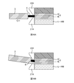
- FIG. 16A is an explanatory diagram of how the coating is removed.
- the gripping part (not shown: described later) that grips the optical fiber 3 on the left side in the figure is moved to cover the blades 21A and 23A.
- the coating 5 of the optical fiber 3 is removed. Since it is necessary to hook the coating 5 with the blades 21A and 23A when removing the coating 5, the distance between the pair of blades 21A and 23A is narrower than the thickness of the coating 5 (the diameter of the optical fiber 3). It is set slightly wider than the diameter of 4.
- the bare optical fiber 4 moves up and down when the coating 5 is pulled out, and the blades 21A and 23A come into contact with the bare optical fiber 4. Sometimes. For this reason, in order to suppress damage to the bare optical fiber 4, the hardness of the blades 21 ⁇ / b> A and 23 ⁇ / b> A is set lower than the hardness of the bare optical fiber 4. As a result, when the removal of the coating 5 is repeated, the cutting edge is gradually worn.
- the coating 5 is removed while one blade (the lower blade 21A in the drawing) is worn, the timing at which the worn blade 21A tears the coating 5 is delayed. At the same time, slippage occurs between the worn blade 21 ⁇ / b> A and the coating 5, resulting in a problem that the balance of the force applied to the bare optical fiber 4 is lost. When the balance of the force applied to the bare optical fiber 4 is lost, the bare optical fiber 4 is bent, or the bare optical fiber 4 is excessively pressed by the upper blade 23A. May reduce reliability.
- Some embodiments of the present invention are directed to prompting blade replacement when the blade is worn.
- Some embodiments of the invention include: A heating unit having a heater unit for heating the coating of the optical fiber, and a blade for cutting the coating of the optical fiber; A gripper that grips the optical fiber and is movable relative to the heating unit; The coating removing apparatus includes a counting unit that counts the number of coating removals by detecting the separation between the heating unit and the gripping unit.
- FIG. 9 is an explanatory diagram of the counting process of the number of coating removals according to the second embodiment.
- FIG. 10 is a block diagram illustrating a configuration of the coating removal apparatus 10 according to the third embodiment.
- 11A and 11B are explanatory diagrams of the holder detection unit 54.
- FIG. 12 is an explanatory diagram of a counting process of the number of coating removals according to the third embodiment.
- FIG. 13A is an explanatory diagram of the separation detection unit 52 of the fourth embodiment.
- FIG. 13B is an explanatory diagram of a separation detection unit 52 according to a modification of the fourth embodiment.
- FIG. 14 is an explanatory diagram of the counting process of the number of coating removals according to the fifth embodiment.
- 15A and 15B are explanatory diagrams of a configuration example of the proximity holding unit.
- FIG. 16A is an explanatory diagram of how the coating is removed.
- FIG. 16B is an explanatory diagram of how the coating is removed when the blade is worn.
- a heating unit having a heater unit for heating the coating of the optical fiber and a blade for cutting the coating of the optical fiber; a gripping unit that grips the optical fiber and is movable with respect to the heating unit; By detecting the separation between the heating unit and the gripping unit, a coating removal apparatus including a counting unit that counts the number of coating removals becomes clear. According to such a coating removal apparatus, the number of coating removals can be counted, and replacement of the blade can be promoted when the blade is worn.
- the counting unit counts the number of coating removals when detecting the closed state of the lid of the heating unit and detecting the separation between the heating unit and the gripping unit. Thereby, even if the separation between the heating unit and the gripping unit is detected when the lid is in the open state, the coating removal count is not counted, and thus the counting accuracy of the coating removal count can be increased.
- the counting unit permits the next counting of the number of coating removals when the open state of the lid of the heating unit is detected after counting the number of times of coating removal. Thereby, the counting accuracy of the number of coating removals can be increased.
- the counting unit counts the number of coating removals when detecting the heating of the heater unit of the heating unit and detecting the separation between the heating unit and the gripping unit. As a result, even if the separation between the heating unit and the gripping unit is detected when the heater unit is not heated, the coating removal count is not counted, so the counting accuracy of the coating removal count can be increased.
- the shaft includes a shaft that connects the heating unit and the gripping unit and guides the separation between the heating unit and the gripping unit, and a movement amount of the shaft when the heating unit and the gripping unit are separated from each other. It is desirable to detect the separation between the heating unit and the gripping unit by detecting that the predetermined amount has been reached. Thereby, unless the heating part and the grip part are separated from each other by a predetermined amount or more, the number of times of coating removal is not counted, and thus the accuracy of counting the number of times of coating removal can be increased.
- the proximity holding unit maintains a state in which the heating unit and the gripping unit are brought close to each other using magnetic force, and the heating unit and the gripping unit are separated from each other using the magnetic force of the proximity holding unit. It is desirable to detect Thereby, the number of parts can be reduced.
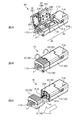
- FIG. 1 is an overall perspective view of a coating removing apparatus 10 according to the present embodiment.
- FIG. 2A to FIG. 2C are explanatory views of the state when the coating is removed.
- the coating removal device 10 is a device that removes the coating of the optical fiber.
- the object of the coating removal is the optical fiber tape 1 having a plurality of optical fibers 3 here, but may be a single-core optical fiber.
- the coating removal apparatus 10 of the present embodiment heats and softens the coating material 5 (hereinafter simply referred to as coating) that coats the outer periphery of the bare optical fiber 4 (see FIG. 16A), and adheres the bare optical fiber 4 to the coating.
- the coating removal apparatus 10 of this embodiment may be called a hot jacket stripper.
- the moving direction of the main body part and the grip part 30 is the front-rear direction
- the main body part side is “front”
- the grip part 30 side is “rear”.
- the front-rear direction may be referred to as a “separation direction”, a “proximity direction”, or a “slide direction”.
- the direction perpendicular to the bottom surface of the holder accommodating portion 311 of the gripping portion 30 is defined as “up and down direction”, and the side in which the holder 7 is accommodated is “upward” when viewed from the bottom surface of the holder accommodating portion 311.
- the side of the main body 31) is “down”.
- the coating removal apparatus 10 includes a heating unit 20 and a gripping unit 30.
- the heating unit 20 is a member that heats the coating of the optical fiber.
- the heating unit 20 has a pair of blades 21A and 23A for removing the coating.
- the heating unit 20 includes a heating side main body 21 and a heating side lid part 23, and a blade is provided on each of the heating side main body 21 and the heating side lid part 23.
- the heating side main body 21 is a member constituting the main body of the heating unit 20.
- the heating side main body 21 includes a blade 21 ⁇ / b> A and a heater unit 211.
- the blade 21A is a member that cuts the coating and removes the coating by hooking.
- the heater unit 211 is a heat source for heating the coating of the optical fiber.
- the heater unit 211 also has a function as a mounting unit for mounting the end of the optical fiber. Specifically, the heater 211 is formed in a groove shape along the front-rear direction, and the end of the optical fiber can be placed in a state where the end of the optical fiber is guided in the front-rear direction.
- the heating-side main body 21 is provided with a power switch 21B, an LED lamp 71A (output unit 71), and the like.
- the heating side lid portion 23 is a lid member that can be opened and closed with respect to the heating side main body 21.
- the heating side lid part 23 has a blade 23 ⁇ / b> A and a holding part 231.
- the holding part 231 is a part for holding the end part of the optical fiber by sandwiching the end part of the optical fiber with the heater part 211 of the heating side main body 21.
- the heating-side lid portion 23 may also be provided with a heat source (heater portion 211) for heating the coating of the optical fiber.
- the grip portion 30 is a member that grips the optical fiber.
- the gripper 30 grips the optical fiber by gripping the holder 7 that holds the optical fiber.
- the grip portion 30 may grip the optical fiber indirectly through a member other than the holder 7 or may directly grip the optical fiber.
- the grip part 30 is configured to be movable in the front-rear direction with respect to the heating part 20 (see FIG. 2C).
- the grip portion 30 includes a grip side main body 31 and a grip side lid portion 33.
- the grip side main body 31 is a member constituting the main body of the grip portion 30.
- the grip-side main body 31 has a holder accommodating portion 311.
- the holder accommodating portion 311 is a portion that accommodates the holder 7 holding the optical fiber.
- the grip-side lid portion 33 is a lid member that can be opened and closed with respect to the grip-side main body 31.
- the grip side lid portion 33 has a holder holding portion 331.
- the holder holding part 331 is a part for holding the holder 7 by sandwiching the holder 7 holding the optical fiber with the holding-side main body 31.
- the heating unit 20 and the gripping unit 30 are connected via a shaft 41 (see FIG. 2C).
- the shaft 41 is a member that connects the heating unit 20 and the gripping unit 30 and guides relative movement between the heating unit 20 and the gripping unit 30.
- one end of the shaft 41 is fixed to the grip portion 30, and when the grip portion 30 moves relative to the heating portion 20, the shaft 41 also moves relative to the heating portion 20.
- the shaft 41 may be fixed to the heating unit 20 side.
- the operator turns on the power switch 21B of the coating removal apparatus 10, and then opens the heating side lid 23 and the grip side lid 33 as shown in FIG. 2A.
- the holder 7 holding the optical fiber 3 here, the optical fiber tape 1 is accommodated in the holder accommodating portion 311 of the grip portion 30, and the end portion of the optical fiber 3 is placed on the heater portion 211 of the heating side main body 21. .
- the optical fiber 3 is set in the coating removal apparatus 10.
- the operator closes the heating side lid 23 and the grip side lid 33 as shown in FIG. 2B.
- the heating side lid 23 is closed, the pair of blades 21A and 23A cuts the coating of the optical fiber 3.
- the heating-side lid portion 23 is closed, the end portion of the optical fiber 3 is sandwiched between the heater portion 211 of the heating-side main body 21 and the holding portion 231 of the heating-side lid portion 23, and the end portion of the optical fiber 3.
- the coating is heated by the heater unit 211.
- the lid detection unit 51 detects the closed state of the heating side lid unit 23, heating of the heater unit 211 is started.
- the coating at the end of the optical fiber is heated, the coating is softened, the adhesion between the bare optical fiber 4 and the coating is reduced, and the coating is easily removed.
- the worker moves the gripping part 30 to the rear side with respect to the heating part 20 with the heating-side cover part 23 and the gripping-side cover part 33 closed. And the grip portion 30 are separated. As a result, the coating at the end of the optical fiber is pulled out by the pair of blades 21A and 23A (see FIG. 16A), and the coating of the optical fiber is removed.
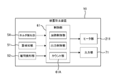
- FIG. 3 is a block diagram showing the configuration of the coating removal apparatus 10.
- the coating removal apparatus 10 includes a control unit 61, various detection units (such as a lid detection unit 51), and an output unit 71 (such as an LED lamp 71A).
- the control unit 61 has a function of controlling the coating removal apparatus 10.
- the control unit 61 includes, for example, an arithmetic processing device or a storage device, and various processing is realized by the arithmetic processing device executing a program stored in the storage device. Detection results of various detection units are input to the control unit 61.
- the control unit 61 controls the heater unit 211 and the output unit 71 based on the detection results of the various detection units.
- the lid detector 51 is a member that detects opening and closing of the heating side lid 23.
- the lid detector 51 has a protruding piece 23B (see FIG. 1) provided on the heating side lid 23.
- a switch, a sensor, or the like of the heating side body 21 is provided.
- a detection unit (not shown in FIG. 1; see FIGS. 4A to 4C) detects the protruding piece 23B, thereby detecting that the heating-side lid unit 23 is closed (closed state).
- 4A to 4C are explanatory diagrams of a configuration example of the lid detection unit 51 (51A to 51C).
- the protruding piece 23B (see FIG. 1) of the heating side lid 23 turns on / off the switch (detection unit) of the heating side body 21 in response to opening and closing of the heating side lid 23.
- the closed state (and open state) of the heating side cover part 23 is detected.
- a magnet sensor (detection unit) is provided on the heating-side main body 21, a magnet is provided on the protruding piece 23B of the heating-side lid 23, and a heating-side lid unit is illustrated.
- the closed state (and the open state) of the heating side lid portion 23 is detected by the change in magnetism detected by the magnet sensor (detection portion) according to the opening and closing of the 23.
- the protruding piece 23B (see FIG. 1) of the heating side lid part 23 detects the detection light of the photo sensor (detection unit) of the heating side body 21 in response to opening and closing of the heating side lid part 23. By blocking, the closed state (and open state) of the heating side lid 23 is detected.
- the lid detection unit 51 is not limited to the above configuration as long as it can detect the closed state (or open state) of the heating side lid unit 23.
- the detection result of the lid detection unit 51 is output to the control unit 61.
- the controller 61 detects the closed state of the heating side lid 23 based on the detection result of the lid detector 51
- the controller 61 causes the heater 211 to start heating.
- the control unit 61 stops the heating of the heater unit 211 when detecting the open state of the heating side lid unit 23 based on the detection result of the lid detection unit 51.
- the control unit 61 serves as a heating control unit that controls the heater unit 211.
- the controller 61 detects the closed state of the heating side lid 23 based on the detection result of the lid detector 51, the controller 61 turns on the LED lamp 71A (output unit 71) after a predetermined time has elapsed. Accordingly, it is possible to notify the worker that the coating on the end of the optical fiber has been heated, or to prompt the worker to move the grip portion 30 shown in FIG. 2C.
- the control unit 61 is an output control unit that controls the output unit 71.
- the covering removal apparatus 10 includes, as the output unit 71, a display unit such as an LED lamp 71A, a speaker (not shown) that outputs sound, and the like. As will be described later, the LED lamp 71A and the speaker (not shown) serve as a notification unit that notifies that the number of coating removals has reached a predetermined value.
- the covering removal apparatus 10 may include a display unit capable of displaying a numerical value (for example, a count value described later) as the output unit 71.
- a display unit capable of displaying a numerical value for example, a count value described later
- examples of the display unit (output unit 71) capable of displaying a count value include a small liquid crystal monitor capable of displaying information other than numerical values, and a segment display device whose main purpose is to display numerical values.
- the coating removal apparatus 10 may include a communication unit that transmits and receives data (data including a count value described later) to an external device as the output unit 71.
- the coating removal apparatus 10 includes a separation detection unit 52 for detecting separation between the heating unit 20 and the grip unit 30 (see FIG. 3).
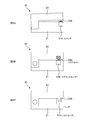
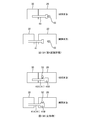
- 5A to 5C are explanatory diagrams of a configuration example of the separation detection unit 52 (52A to 52C).
- the separation detector 52A shown in FIG. 5A is configured by a mechanical switch.
- 5A is an explanatory diagram of a state (proximity state) before the separation detection unit 52A detects the separation between the heating unit 20 and the grip unit 30.
- FIG. The lower diagram of FIG. 5A is an explanatory diagram of a state (separation state) in which the separation detection unit 52A detects the separation between the heating unit 20 and the gripping unit 30.
- the separation detection unit 52A illustrated in FIG. 5A turns on / off the switch (detection unit) of the heating-side main body 21 in accordance with the proximity / separation of the heating unit 20 and the gripping unit 30, thereby causing the heating unit 20 and the gripping unit 30.
- the separation state (or proximity state) is detected.
- the separation detection unit 52 ⁇ / b> A is disposed on the opposing surface of the heating unit 20 and the grip unit 30.
- the switch that constitutes the separation detection unit 52A is disposed in the heating unit 20, and the switch is turned on / off when the facing surface (detected unit) of the gripping unit 30 contacts / separates the switch.
- the switch constituting the separation detection unit 52A may be disposed on the grip unit 30 side.
- the separation detection unit 52B shown in FIG. 5B is configured by a magnet sensor.
- the heating-side main body 21 is provided with a magnet sensor (detection part), and the grip part 30 is provided with a magnet (detected part).
- the separation detection unit 52A shown in FIG. 5B is a separation state between the heating unit 20 and the gripping unit 30 due to a change in magnetism detected by the magnet sensor (detection unit) according to the proximity and separation between the heating unit 20 and the gripping unit 30. (Or proximity state) is detected.
- the separation detection unit 52C shown in FIG. 5C is configured by a photosensor.
- the heating-side main body 21 is provided with a photosensor (detecting unit), and the gripping unit 30 is provided with a light shielding piece (detected portion).
- the light shielding piece blocks or projects the detection light of the photosensor (detection unit) according to the proximity / separation of the heating unit 20 and the gripping unit 30, thereby separating (or approaching) the heating unit 20 and the gripping unit 30. Status).
- the separation detection unit 52 only needs to detect the separation state (or proximity state) between the heating unit 20 and the gripping unit 30. Therefore, the separation detection unit 52 is not limited to the configuration shown in FIGS. 5A to 5C.
- the coating removal apparatus 10 includes a counting unit 61A that counts the number of coating removals (see FIG. 3).
- the count unit 61A is configured by the control unit 61, but may be configured by a mechanical counter.
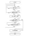
- FIG. 6 is an explanatory diagram of the counting process of the number of coating removals according to the first embodiment.
- the count unit 61A determines whether or not the closed state of the heating side lid unit 23 is detected based on the detection result of the lid detection unit 51 (S101). If the count part 61A does not detect the closed state of the heating side lid part 23 (NO in S101), the counting part 61A repeats the determination process of S101 until the closed state of the heating side lid part 23 is detected.
- the counting unit 61 ⁇ / b> A detects the closed state of the heating-side lid unit 23 (YES in S ⁇ b> 101)
- the counting unit 61 ⁇ / b> A next detects the separation state between the heating unit 20 and the gripping unit 30 based on the detection result of the separation detection unit 52. It is determined whether or not (S102).
- the count unit 61A If the count unit 61A does not detect the separation state between the heating unit 20 and the gripping unit 30 based on the detection result of the separation detection unit 52 (NO in S102), the count unit 61A returns to the determination process in S101.
- the counting unit 61A detects the separation state between the heating unit 20 and the gripping unit 30 based on the detection result of the separation detection unit 52 (YES in S102), the count unit 61A adds one count value of the number of coating removals (S103). .
- the counting unit 61A detects the closed state of the heating side lid 23 based on the detection result of the lid detection unit 51 (YES in S101), and the detection result of the separation detection unit 52 Based on this, when the separation state between the heating unit 20 and the gripping unit 30 is detected (YES in S102), the count value of the number of coating removals is incremented by one (S103). As a result, as shown in FIG. 2C, the worker moves the grip 30 to the rear side with respect to the heating unit 20 with the heating side lid 23 and the grip side lid 33 closed. When the grip part 30 is separated (when the coating at the end of the optical fiber is removed), the count value indicating the number of times of coating removal can be increased by one. In the present embodiment, the count unit 61A stores the count value in the storage device.
- the fact that the closed state of the heating-side lid portion 23 is detected (S101) becomes a count value addition condition, so that the count value increases when the coating is not removed. Since this can be suppressed, the counting accuracy of the coating removal count (coincidence accuracy between the coating removal count and the count value) can be increased.
- the count unit 61A counts the next number of times of coating removal (S101) when detecting the open state of the heating side lid 23 (YES in S105). To S103). That is, in this embodiment, after adding one count value (S103), if the open state of the heating side lid 23 is not detected (YES in S105), the next coating removal count is counted. I will not. In order to remove the coating on the end of the next optical fiber, after removing the coating on the end of the optical fiber as shown in FIG. This is because it is necessary to open the portion 23 (and the grip side lid portion 33). Further, after removing the coating at the end of the optical fiber as shown in FIG.
- the control unit 61 when the count value reaches a predetermined value (YES in S104), the control unit 61 notifies the output unit 71 that the number of times of covering removal has reached the predetermined value. Specifically, when the count value reaches a predetermined value (YES in S104), the control unit 61 turns on the LED lamp 71A, which is the output unit 71, and confirms that the number of times of coating removal has reached the predetermined value. (S106). Thereby, when the blades 21A and 23A are worn, it is possible to prompt the operator to replace the blades 21A and 23A. Note that the notification method of the output unit 71 is not limited to the lighting of the LED lamp 71A.
- the control unit 61 sounds a buzzer with a speaker serving as the output unit 71, thereby informing the operator that the number of times of covering removal has reached the predetermined value. You may notify.
- the control unit 61 may display the count value of the number of coating removals on the display unit (output unit 71).
- the display of the count value is not limited to the electronic display, but may be a mechanical display (for example, a dial display).
- the control unit 61 does not have to determine whether or not the count value has reached a predetermined value (S104) or perform notification (S106) using the output unit 71.
- the counting unit 61A detects the closed state of the heating side lid 23 based on the detection result of the lid detection unit 51 (YES in S101), and based on the detection result of the separation detection unit 52.
- the count value of the number of coating removals was added by 1 (S103).
- FIG. 7 is an explanatory diagram of the heating profile of the heater unit 211.
- the horizontal axis of the graph in the figure indicates time, and the vertical axis indicates the temperature of the heater unit 211.
- the control unit 61 (heating control unit) causes the heater unit 211 to start heating when detecting the closed state of the heating side lid unit 23 based on the detection result of the lid detection unit 51.
- the temperature of the heater unit 211 rises and reaches a predetermined heating temperature.
- the control unit 61 performs constant temperature control of the heater unit 211 so as to be maintained at a predetermined heating temperature, and stops the heating of the heater unit 211 when detecting the open state of the heating side lid unit 23.
- FIG. 8 is a block diagram illustrating a configuration of the coating removal apparatus 10 according to the second embodiment.
- the coating removal apparatus 10 according to the second embodiment includes a heating detection unit 53.
- the heating detection unit 53 is a member that detects the heating of the heater unit 211.
- the heating detection unit 53 is, for example, a temperature sensor, and may detect the heating of the heater unit 211 based on the detected temperature. In this case, the detection result of the temperature sensor of the heating detection unit 53 may be used for constant temperature control of the heater unit 211 (see FIG. 7).
- the heating detection unit 53 may detect the heating of the heater unit 211 by detecting energization to the heater unit 211.
- FIG. 9 is an explanatory diagram of the coating removal count process according to the second embodiment.
- the count unit 61A determines whether the heating of the heater unit 211 is detected based on the detection result of the heating detection unit 53 (S201). If the heating of the heater 211 is not detected (NO in S201), the counting unit 61A repeats the determination process of S201 until the heating of the heater 211 is detected. When the counting unit 61A detects the heating of the heater unit 211 (YES in 201), it is next detected whether or not the separated state between the heating unit 20 and the gripping unit 30 is detected based on the detection result of the separation detecting unit 52. Is determined (S202).
- the count unit 61A If the count unit 61A does not detect the separation state between the heating unit 20 and the gripping unit 30 based on the detection result of the separation detection unit 52 (NO in S202), the count unit 61A returns to the determination process in S201.
- the counting unit 61A detects the separation state between the heating unit 20 and the gripping unit 30 based on the detection result of the separation detection unit 52 (YES in S202), the count unit 61A adds one count value of the number of coating removals (S203). .
- the count unit 61A detects the heating of the heater unit 211 based on the detection result of the heating detection unit 53 (YES in S201), and heats based on the detection result of the separation detection unit 52.
- the count value of the number of coating removals is incremented by one (S203).
- the count unit 61A may determine whether or not heating is started in S201, and determines whether or not the heater unit 211 has reached a predetermined temperature based on the detection result of the temperature sensor. May be.
- the second embodiment as a condition for adding the count value, not only detecting the separated state of the heating unit 20 and the gripping unit 30 (S202) but also detecting the heating of the heater unit 211 (S201). It is a condition. For this reason, when the heater part 211 is not heated, even if the separated state between the heating part 20 and the grip part 30 is detected, the count value is not added. This is because the heater unit 211 is in a heated state when the heating unit 20 and the gripping unit 30 are separated to remove the coating. As in the second embodiment, when the heating of the heater unit 211 is detected (S201) is a count value addition condition, an increase in the count value when the coating is not removed can be suppressed. Therefore, it is possible to improve the counting accuracy of the number of times of coating removal (the accuracy of matching between the number of times of coating removal and the count value).
- next coating removal count may be counted regardless of whether or not the open state of the heating side lid 23 is detected (S105). Further, when the count value reaches the predetermined value (YES in S104), the count value may be simply displayed on the display unit instead of being notified (S106) using the output unit 71. This also applies to the embodiments described later.
- FIG. 10 is a block diagram illustrating a configuration of the coating removal apparatus 10 according to the third embodiment.
- the coating removal apparatus 10 according to the third embodiment includes a holder detection unit 54.
- FIG. 11A and 11B are explanatory views of the holder detection unit 54.
- FIG. FIG. 11A is an explanatory diagram of a state before the holder detection unit 54 detects the holder 7 (undetected state).
- FIG. 11B is an explanatory diagram of a state (detection state) in which the holder detection unit 54 detects the holder 7.
- the holder detection unit 54 is a member that detects the holder 7 accommodated in the holder accommodation unit 311 of the grip unit 30.
- the holder detection unit 54 is configured by a switch that is turned on / off in accordance with the attachment / detachment of the holder 7 to / from the holder accommodating unit 311.
- the holder detection part 54 may be comprised with the sensors (a magnet sensor, a photo sensor, etc.) which detect the holder 7 magnetically or optically.
- FIG. 12 is an explanatory diagram of a process for counting the number of coating removals according to the third embodiment.
- the count unit 61A determines whether or not it is detected that the holder 7 is stored in the holder storage unit 311 based on the detection result of the holder detection unit 54 (S301). If the count unit 61A does not detect that the holder 7 is stored in the holder storage unit 311 (NO in S301), the count unit 61A repeats the determination process in S301 until the holder is detected. When the count unit 61 ⁇ / b> A detects that the holder 7 is stored in the holder storage unit 311 (YES in S ⁇ b> 301), the counting unit 61 ⁇ / b> A next changes the closed state of the heating side cover unit 23 based on the detection result of the cover detection unit 51.
- the counting unit 61A It is determined whether or not it is detected (S302). If the counting unit 61A does not detect the closed state of the heating-side lid 23 (NO in S302), the counting unit 61A returns to the determination process of S301. Count unit 61A detects that holder 7 is stored in holder storage unit 311 based on the detection result of holder detection unit 54 (YES in S301), and heats based on the detection result of lid detection unit 51. When the closed state of the side lid portion 23 is detected (YES in S302), it is determined whether or not the separation state between the heating unit 20 and the gripping unit 30 is detected based on the detection result of the separation detection unit 52 (S303). ).
- the counting unit 61A If the count unit 61A does not detect the separation state between the heating unit 20 and the gripping unit 30 based on the detection result of the separation detection unit 52 (NO in S303), the counting unit 61A returns to the determination process in S301. When the counting unit 61A detects the separated state between the heating unit 20 and the gripping unit 30 based on the detection result of the separation detecting unit 52 (YES in S303), the count unit 61A adds one count value of the number of coating removals (S304). .
- the count unit 61A detects that the holder 7 is stored in the holder storage unit 311 based on the detection result of the holder detection unit 54 (YES in S301), and the lid detection unit.
- the closed state of the heating side lid 23 is detected based on the detection result of 51 (YES in S302), and the separation state of the heating unit 20 and the gripping unit 30 is detected based on the detection result of the separation detection unit 52.
- YES in S303 one count value of the number of coating removals is added (S304).
- the count value addition condition the closed state of the heating side lid 23 is detected (S302), and the separated state of the heating unit 20 and the gripping unit 30 is detected (S303). ) As well as that the holder 7 is accommodated in the holder accommodating portion 311 (S301). For this reason, when the holder 7 is not accommodated in the holder accommodating part 311, even if the heating side cover part 23 detects the separated state of the heating part 20 and the holding part 30 under the closed state, the count value is not added. . Thereby, the counting accuracy of the number of times of coating removal (the accuracy of matching between the number of times of coating removal and the count value) can be increased.
- the count unit 61A detects that the holder 7 is stored in the holder storage unit 311 based on the detection result of the holder detection unit 54 (YES in S301), and the detection result of the separation detection unit 52 Based on this, when the separated state of the heating unit 20 and the gripping unit 30 is detected (YES in S303), the count value of the number of coating removals is incremented by one (S304).
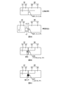
- FIG. 13A is an explanatory diagram of the separation detection unit 52 of the fourth embodiment.
- 13A is an explanatory diagram of a state (proximity state) before the separation detection unit 52 detects the separation between the heating unit 20 and the gripping unit 30.
- FIG. The lower diagram of FIG. 13A is an explanatory diagram of a state (separation state) in which the separation detection unit 52 detects the separation between the heating unit 20 and the grip unit 30.
- the shaft 41 in the figure is a member that connects the heating unit 20 and the gripping unit 30 and guides the relative movement between the heating unit 20 and the gripping unit 30 (see also FIG. 2C).
- one end (rear end, left end in the figure) of the shaft 41 is fixed to the grip portion 30, and the other end of the shaft 41 is heated when the grip portion 30 moves relative to the heating portion 20. It moves inside the unit 20.
- the separation detecting unit 52 of the fourth embodiment detects the separation between the heating unit 20 and the gripping unit 30 by detecting the movement of the shaft 41 when the heating unit 20 and the gripping unit 30 are separated from each other.
- the separation detection unit 52 is configured by a mechanical switch, and the switch (detection unit) is disposed to face the end (detected unit) of the shaft 41 on the heating unit 20 side.
- the separation detection unit 52 detects a separation state (or proximity state) between the heating unit 20 and the gripping unit 30 when the shaft 41 is separated from the switch when the heating unit 20 and the gripping unit 30 are separated from each other.
- FIG. 13B is an explanatory diagram of the separation detection unit 52 according to a modification of the fourth embodiment.
- An end portion of the shaft 41 on the gripping portion 30 side is fixed to the gripping portion 30, and a flange portion 41 ⁇ / b> B protruding outward from the shaft portion 41 ⁇ / b> A of the shaft 41 on the end portion of the shaft 41 on the heating portion 20 side. Is formed.
- the switch (detection unit) constituting the separation detection unit 52 is disposed at a position facing the shaft portion 41A of the shaft 41 in the proximity state, and when the movement amount of the shaft 41 reaches a predetermined amount, It arrange
- the count unit 61A detects the separation state of the heating unit 20 and the gripping unit 30 based on the detection result of the separation detection unit 52 when the heating unit 20 and the gripping unit 30 are separated by a predetermined amount or more. (See S102, S202, S303). In other words, the count value of the number of times of coating removal is not added unless the heating unit 20 and the gripping unit 30 are separated by a predetermined amount or more. For this reason, the counting accuracy of the number of times of coating removal (the accuracy of matching between the number of times of coating removal and the count value) can be improved.
- one end of the shaft 41 is fixed to the grip portion 30, and the switch (detection portion) of the separation detection portion 52 is disposed in the heating portion 20.
- one end of the shaft 41 may be fixed to the gripping unit 30 and a switch constituting the separation detection unit 52 may be disposed in the gripping unit 30.
- the separation detection unit 52 is configured by a switch.
- the separation detection unit 52 is configured by a sensor (such as a magnet sensor or a photo sensor) that detects the holder 7 magnetically or optically. Also good.
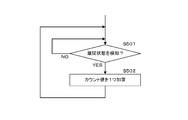
- FIG. 14 is an explanatory diagram of the counting process of the number of coating removals according to the fifth embodiment.
- the counting unit 61A when the counting unit 61A detects the separated state between the heating unit 20 and the gripping unit 30 based on the detection result of the separation detecting unit 52 (YES in S501), the count unit 61A calculates the count value of the number of coating removals. One is added (S502). Even with such processing alone, when the worker separates the heating unit 20 and the gripping unit 30 and the coating on the end of the optical fiber is removed (see FIG. 2C), the count value indicating the number of coating removals is set to 1. Can be increased.
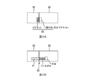
- the coating removal apparatus 10 includes the proximity holding unit 45 that maintains the proximity state in which the heating unit 20 and the gripping unit 30 are brought close to each other.
- FIG. 15A and 15B are explanatory diagrams of a configuration example of the proximity holding unit 45.
- FIG. 15A and 15B are explanatory diagrams of a configuration example of the proximity holding unit 45.
- the proximity holding unit 45 illustrated in FIG. 15A includes a magnet and a magnetic body, the magnet is disposed in the holding unit 30, the magnetic body is disposed in the heating unit 20, and the heating unit 20 uses magnetic force. And the grip portion 30 are kept close to each other.
- a magnet may be arrange
- the separation between the heating unit 20 and the gripping unit may be detected using the magnetic force of the magnet of the proximity holding unit 45.
- the magnet sensor (separation detection unit 52) shown in FIG. 5B may be arranged so as to face the magnet of the gripping unit 30 in FIG. 15A (the magnet constituting the proximity holding unit 45).
- the magnet can be used as the separation detecting unit 52 and the proximity holding unit 45, and the number of components can be reduced.
- the proximity holding part 45 shown in FIG. 15B is configured by a coil spring.
- the coil spring is disposed in a state of being compressed and deformed between the inner wall surface of the heating unit 20 and the flange portion 41 ⁇ / b> B of the shaft 41. Since the coil spring is disposed in a state of being compressed and deformed in advance, the proximity state in which the heating unit 20 and the gripping unit 30 are brought close to each other is maintained by the repulsive force of the coil spring.
- the heating unit 20 and the gripping unit can be used when the coating is not removed. 30 can be prevented from being separated from each other, and the counting accuracy of the coating removal frequency (coincidence accuracy between the coating removal frequency and the count value) can be increased.
Landscapes
- Physics & Mathematics (AREA)
- General Physics & Mathematics (AREA)
- Optics & Photonics (AREA)
- Light Guides In General And Applications Therefor (AREA)
Abstract
【課題】刃が摩耗したときに刃の交換を促すこと。 【解決手段】本開示の被覆除去装置は、光ファイバの被覆を加熱するためのヒータ部と前記光ファイバの前記被覆に切り込みを入れる刃とを有する加熱部と、前記光ファイバを把持して前記加熱部に対して移動可能な把持部と、前記加熱部と前記把持部との離間を検知することにより、被覆除去回数をカウントするカウント部とを備える。
Description
本発明は、光ファイバの被覆除去装置に関する。
光ファイバの被覆を除去する被覆除去装置として、例えば特許文献1、2に記載の装置が知られている。特許文献1、2に記載の被覆除去装置では、光ファイバの除去すべき被覆を加熱して軟化させ、裸光ファイバと被覆との密着力を小さくして、被覆を除去することが行われている。
図16Aは、被覆除去の様子の説明図である。一対の刃21A,23Aが被覆除去開始位置で被覆5に切り込みを入れた後、図中左側の光ファイバ3を把持する把持部(不図示:後述)を移動させて、刃21A,23Aで被覆5を引き抜くことによって、光ファイバ3の被覆5が除去される。被覆5の除去時に刃21A,23Aで被覆5を引っ掛ける必要があるため、一対の刃21A,23Aの間隔は、被覆5の厚み(光ファイバ3の径)よりは狭くなっており、裸光ファイバ4の径よりも若干広く設定されている。
一対の刃21A,23Aの間隔が裸光ファイバ4の径よりも広いことに起因して、被覆5の引き抜き時に裸光ファイバ4が上下に動き、刃21A,23Aが裸光ファイバ4に接触することがある。このため、裸光ファイバ4の損傷を抑制するために、刃21A,23Aの硬度は裸光ファイバ4の硬度よりも低く設定されている。この結果、被覆5の除去が繰り返されると、刃先が徐々に摩耗する。
摩耗した刃21A,23Aで被覆5の除去が行われると、被覆5を完全に除去できずに、被覆5の一部が裸光ファイバ4に残存するという問題が発生する。被覆5の一部が裸光ファイバ4に残存し、その後の清掃工程においても被覆5を除去しきれなかった場合には、融着接続工程で裸光ファイバ4の表面に残存した被覆5が燃焼してしまい、光ファイバ3の長期信頼性を低下させるおそれがある。
また、図16Bに示すように、一方の刃(図中の下側の刃21A)が摩耗した状態で被覆5の除去が行われると、摩耗した刃21Aが被覆5を切り裂くタイミングが遅れてしまうとともに、摩耗した刃21Aと被覆5との間で滑りが生じてしまい、この結果、裸光ファイバ4にかかる力のバランスが崩れるという問題が生じる。裸光ファイバ4にかかる力のバランスが崩れた場合には、裸光ファイバ4に曲がりが発生したり、裸光ファイバ4が上側の刃23Aに過度に押圧されたりして、光ファイバ3の長期信頼性を低下させるおそれがある。
上記のような問題を防ぐためには、刃が摩耗したときに刃を交換することが望ましい。但し、刃の摩耗状況は視認し難いため、刃の交換時期に気付かないまま、被覆除去が行われてしまいやすい。
本発明の幾つかの実施形態は、刃が摩耗したときに刃の交換を促すことを目的とする。
本発明の幾つかの実施形態は、
光ファイバの被覆を加熱するためのヒータ部と、前記光ファイバの前記被覆に切り込みを入れる刃とを有する加熱部と、
前記光ファイバを把持して前記加熱部に対して移動可能な把持部と、
前記加熱部と前記把持部との離間を検知することにより、被覆除去回数をカウントするカウント部と
を備えた被覆除去装置である。
光ファイバの被覆を加熱するためのヒータ部と、前記光ファイバの前記被覆に切り込みを入れる刃とを有する加熱部と、
前記光ファイバを把持して前記加熱部に対して移動可能な把持部と、
前記加熱部と前記把持部との離間を検知することにより、被覆除去回数をカウントするカウント部と
を備えた被覆除去装置である。
本発明の他の特徴については、後述する明細書及び図面の記載により明らかにする。
本発明の幾つかの実施形態によれば、刃が摩耗したときに刃の交換を促すことができる。
後述する明細書及び図面の記載から、少なくとも以下の事項が明らかとなる。
光ファイバの被覆を加熱するためのヒータ部と前記光ファイバの前記被覆に切り込みを入れる刃とを有する加熱部と、前記光ファイバを把持して前記加熱部に対して移動可能な把持部と、前記加熱部と前記把持部との離間を検知することにより、被覆除去回数をカウントするカウント部とを備えた被覆除去装置が明らかとなる。このような被覆除去装置によれば、被覆除去回数をカウントすることができ、刃が摩耗したときに刃の交換を促すことができる。
前記カウント部は、前記加熱部の蓋部の閉状態を検知し、且つ、前記加熱部と前記把持部との離間を検知したときに、被覆除去回数をカウントすることが望ましい。これにより、蓋部が開状態のときに前記加熱部と前記把持部との離間を検知しても、被覆除去回数がカウントされないため、被覆除去回数のカウント精度を高めることができる。
前記カウント部は、前記被覆除去回数をカウントした後、前記加熱部の蓋部の開状態を検知した場合に、次の前記被覆除去回数のカウントを許可することが望ましい。これにより、被覆除去回数のカウント精度を高めることができる。
前記カウント部は、前記加熱部の前記ヒータ部の加熱を検知し、且つ、前記加熱部と前記把持部との離間を検知したときに、被覆除去回数をカウントすることが望ましい。これにより、ヒータ部が加熱されていないときに前記加熱部と前記把持部との離間を検知しても、被覆除去回数がカウントされないため、被覆除去回数のカウント精度を高めることができる。
前記把持部は、前記光ファイバを保持したホルダを収容するホルダ収容部を有し、前記カウント部は、前記ホルダが前記ホルダ収容部に収容されたことを検知し、且つ、前記加熱部と前記把持部との離間を検知したときに、被覆除去回数をカウントすることが望ましい。これにより、ホルダがホルダ収容部に収容されていないときに前記加熱部と前記把持部との離間を検知しても、被覆除去回数がカウントされないため、被覆除去回数のカウント精度を高めることができる。
前記加熱部と前記把持部とを連結するとともに、前記加熱部と前記把持部との離間をガイドするシャフトを備え、前記加熱部と前記把持部とを離間させたときの前記シャフトの移動量が所定量に達したことを検知することによって、前記加熱部と前記把持部との離間を検知することが望ましい。これにより、加熱部と把持部とが所定量以上で離間しなければ、被覆除去回数がカウントされないため、被覆除去回数のカウント精度を高めることができる。
前記加熱部と前記把持部とを近接させた状態を維持する近接保持部を備えることが望ましい。これにより、被覆を除去していないときに加熱部と把持部とが離間することを抑制できるため、被覆除去回数のカウント精度を高めることができる。
前記近接保持部は、磁力を利用して前記加熱部と前記把持部とを近接させた状態を維持し、前記近接保持部の前記磁力を利用して、前記加熱部と前記把持部との離間を検知することが望ましい。これにより、部品点数を削減できる。
前記被覆除去回数が所定値に達したことを報知するための報知部を備えることが望ましい。これにより、作業者に刃の交換を促すことができる。
前記被覆除去回数を表示するための表示部を備えることが望ましい。これにより、作業者に刃の交換を促すことができる。
===第1実施形態===
<被覆除去装置10の基本構成>
図1は、本実施形態の被覆除去装置10の全体斜視図である。図2A~図2Cは、被覆除去時の様子の説明図である。
<被覆除去装置10の基本構成>
図1は、本実施形態の被覆除去装置10の全体斜視図である。図2A~図2Cは、被覆除去時の様子の説明図である。
被覆除去装置10は、光ファイバの被覆を除去する装置である。被覆除去の対象は、ここでは複数の光ファイバ3を有する光ファイバテープ1であるが、単心光ファイバであっても良い。本実施形態の被覆除去装置10は、裸光ファイバ4(図16A参照)の外周を被覆する被覆材5(以下、単に被覆という)を加熱して軟化させ、裸光ファイバ4と被覆との密着力を小さくして、被覆を除去する装置である。本実施形態の被覆除去装置10は、ホットジャケットストリッパと呼ばれることもある。
以下では、図1に示す方向に従って説明を行うことがある。すなわち、本体部と把持部30との移動方向のことを前後方向とし、本体部の側を「前」とし、把持部30の側を「後」とする。なお、前後方向のことを「離間方向」、「近接方向」、若しくは「スライド方向」と呼ぶこともある。また、把持部30のホルダ収容部311の底面に垂直な方向を「上下方向」とし、ホルダ収容部311の底面から見て、ホルダ7の収容される側を「上」とし、逆側(把持側本体31の側)を「下」とする。また、前後方向及び上下方向に垂直な方向を「左右方向」とし、後側から前側を見たときの右側を「右」とし、左側を「左」とする(ここでは、蓋部(加熱側蓋部23及び把持側蓋部33)のヒンジ側が「左」であり、開閉側が「右」である)。
被覆除去装置10は、加熱部20と、把持部30とを備えている。
加熱部20は、光ファイバの被覆を加熱する部材である。また、加熱部20は、被覆除去のための一対の刃21A,23Aを有する。加熱部20は、加熱側本体21と、加熱側蓋部23とを有しており、加熱側本体21と加熱側蓋部23のそれぞれに刃が設けられている。
加熱側本体21は、加熱部20の本体を構成する部材である。加熱側本体21は、刃21Aと、ヒータ部211とを有する。刃21Aは、被覆に切り込みを入れるとともに、被覆を引っ掛けて除去する部材である。ヒータ部211は、光ファイバの被覆を加熱する熱源である。ヒータ部211は、光ファイバの端部を載置する載置部としての機能も備えている。具体的には、ヒータ部211は、前後方向に沿って溝状に形成されており、光ファイバの端部を前後方向にガイドした状態で光ファイバの端部を載置できる。加熱側本体21には、電源スイッチ21Bや、LEDランプ71A(出力部71)等が設けられている。
加熱側蓋部23は、加熱側本体21に対して開閉可能な蓋部材である。加熱側蓋部23は、刃23Aと、保持部231とを有する。保持部231は、光ファイバの端部を加熱側本体21のヒータ部211との間に挟み込み、光ファイバの端部を保持するための部位である。加熱側蓋部23が閉じられると、光ファイバの端部がヒータ部211に押し付けられて、ヒータ部211によって加熱されることになる。なお、加熱側蓋部23にも、光ファイバの被覆を加熱する熱源(ヒータ部211)が設けられても良い。
把持部30は、光ファイバを把持する部材である。本実施形態では、把持部30は、光ファイバを保持するホルダ7を把持することによって、光ファイバを把持する。但し、把持部30は、ホルダ7以外の部材を介して光ファイバを間接的に把持しても良いし、光ファイバを直接的に把持しても良い。把持部30は、加熱部20に対して前後方向に移動可能に構成されている(図2C参照)。把持部30は、把持側本体31と、把持側蓋部33とを有している。
把持側本体31は、把持部30の本体を構成する部材である。把持側本体31は、ホルダ収容部311を有する。ホルダ収容部311は、光ファイバを保持したホルダ7を収容する部位である。
把持側蓋部33は、把持側本体31に対して開閉可能な蓋部材である。把持側蓋部33は、ホルダ保持部331を有する。ホルダ保持部331は、光ファイバを保持したホルダ7を把持側本体31との間に挟み込み、ホルダ7を把持するための部位である。把持側蓋部33が閉じられると、ホルダ7がホルダ収容部311に押し付けられて、把持側本体31と把持側蓋部33との間にホルダ7が把持されることになる。
加熱部20と把持部30は、シャフト41を介して連結されている(図2C参照)。シャフト41は、加熱部20と把持部30とを連結するとともに、加熱部20と把持部30との相対移動をガイドする部材である。本実施形態では、シャフト41の一端が把持部30に固定されており、加熱部20に対して把持部30が移動するときに、シャフト41も加熱部20に対して移動することになる。但し、シャフト41を加熱部20の側に固定しても良い。
光ファイバの被覆を除去する際には、まず、作業者は、被覆除去装置10の電源スイッチ21Bを入れた後、図2Aに示すように、加熱側蓋部23及び把持側蓋部33を開けて、光ファイバ3(ここでは光ファイバテープ1)を保持したホルダ7を把持部30のホルダ収容部311に収容し、光ファイバ3の端部を加熱側本体21のヒータ部211に載置させる。これにより、光ファイバ3が被覆除去装置10にセットされる。
次に、作業者は、図2Bに示すように、加熱側蓋部23及び把持側蓋部33を閉じる。加熱側蓋部23が閉じられたとき、一対の刃21A,23Aによって光ファイバ3の被覆に切り込みが入ることになる。また、加熱側蓋部23が閉じられると、光ファイバ3の端部が加熱側本体21のヒータ部211と加熱側蓋部23の保持部231との間に挟み込まれ、光ファイバ3の端部の被覆がヒータ部211によって加熱される。なお、後述するように、蓋検知部51が加熱側蓋部23の閉状態を検知すると、ヒータ部211の加熱が開始する。光ファイバの端部の被覆が加熱されると、被覆が軟化し、裸光ファイバ4と被覆との密着力が低下して、被覆を除去しやすい状態になる。
次に、作業者は、図2Cに示すように、加熱側蓋部23及び把持側蓋部33を閉じた状態で、加熱部20に対して把持部30を後側に移動させ、加熱部20と把持部30とを離間させる。これにより、光ファイバの端部の被覆が一対の刃21A,23Aによって引き抜かれて(図16A参照)、光ファイバの被覆が除去されることになる。
図3は、被覆除去装置10の構成を示すブロック図である。被覆除去装置10は、制御部61と、各種検知部(蓋検知部51など)と、出力部71(LEDランプ71Aなど)とを有する。
制御部61は、被覆除去装置10の制御を司る機能を有する。制御部61は、例えば演算処理装置や記憶装置から構成されており、記憶装置に記憶されたプログラムを演算処理装置が実行することにより、各種処理が実現されることになる。制御部61には、各種検知部の検知結果が入力される。制御部61は、各種検知部の検知結果に基づいて、ヒータ部211や出力部71の制御を行うことになる。
蓋検知部51は、加熱側蓋部23の開閉を検知する部材である。蓋検知部51は、加熱側蓋部23に設けられた突出片23B(図1参照)を有しており、加熱側蓋部23が閉じられたときに加熱側本体21のスイッチやセンサ等の検知部(図1では不図示:図4A~図4C参照)が突出片23Bを検知することによって、加熱側蓋部23が閉じられたこと(閉状態)を検知する。
図4A~図4Cは、蓋検知部51(51A~51C)の構成例の説明図である。図4Aに示す蓋検知部51Aは、加熱側蓋部23の開閉に応じて加熱側蓋部23の突出片23B(図1参照)が加熱側本体21のスイッチ(検知部)をオン・オフさせることによって、加熱側蓋部23の閉状態(及び開状態)を検知する。また、図4Bに示す蓋検知部51Bは、加熱側本体21にマグネットセンサ(検知部)が設けられており、加熱側蓋部23の突出片23Bにマグネットが設けられており、加熱側蓋部23の開閉に応じてマグネットセンサ(検知部)の検知する磁気の変化によって、加熱側蓋部23の閉状態(及び開状態)を検知する。図4Cに示す蓋検知部51Cは、加熱側蓋部23の開閉に応じて加熱側蓋部23の突出片23B(図1参照)が加熱側本体21のフォトセンサ(検知部)の検出光を遮断することによって、加熱側蓋部23の閉状態(及び開状態)を検知する。但し、蓋検知部51は、加熱側蓋部23の閉状態(若しくは開状態)を検知できれば、上記の構成に限られるものではない。
蓋検知部51の検知結果は、制御部61に出力される。制御部61は、蓋検知部51の検知結果に基づいて、加熱側蓋部23の閉状態を検知したとき、ヒータ部211に加熱を開始させる。これにより、図2Bに示すように作業者が加熱側蓋部23を閉じたときに、ヒータ部211の加熱が自動的に開始される。また、制御部61は、蓋検知部51の検知結果に基づいて、加熱側蓋部23の開状態を検知したとき、ヒータ部211の加熱を停止させる。これにより、被覆除去後に光ファイバを取り出すために作業者が加熱側蓋部23及び把持側蓋部33を開けたときに、ヒータ部211の加熱が自動的に停止される。このように、制御部61は、ヒータ部211を制御する加熱制御部となる。
また、制御部61は、蓋検知部51の検知結果に基づいて、加熱側蓋部23の閉状態を検知したとき、所定時間経過後にLEDランプ71A(出力部71)を点灯させる。これにより、光ファイバの端部の被覆が加熱されたことを作業者に知らせたり、図2Cに示す把持部30の移動作業を作業者に促したりすることができる。このように、制御部61は、出力部71を制御する出力制御部となる。
被覆除去装置10は、出力部71として、LEDランプ71Aのような表示部や、音を出力するスピーカ(不図示)などを有する。LEDランプ71Aやスピーカ(不図示)は、後述するように、被覆除去回数が所定値に達したことを報知する報知部となる。
被覆除去装置10は、出力部71として、数値(例えば、後述のカウント値)を表示可能な表示部を備えていても良い。なお、カウント値を表示可能な表示部(出力部71)としては、数値以外の情報も表示可能な小型液晶モニタや、数値の表示を行うことを主目的としたセグメント表示装置などがある。また、被覆除去装置10は、出力部71として、外部装置にデータ(後述のカウント値を含むデータ)を送受信する通信部を備えていても良い。
<被覆除去回数のカウント>
本実施形態では、刃21A,23Aが摩耗したときに刃21A,23Aの交換を促すため、被覆除去回数をカウントする。次に説明するように、被覆除去回数のカウントは、加熱部20と把持部30との離間を検知することにより行われている。
本実施形態では、刃21A,23Aが摩耗したときに刃21A,23Aの交換を促すため、被覆除去回数をカウントする。次に説明するように、被覆除去回数のカウントは、加熱部20と把持部30との離間を検知することにより行われている。
・離間検知部52
被覆除去装置10は、加熱部20と把持部30との離間を検知するための離間検知部52を有する(図3参照)。図5A~図5Cは、離間検知部52(52A~52C)の構成例の説明図である。
被覆除去装置10は、加熱部20と把持部30との離間を検知するための離間検知部52を有する(図3参照)。図5A~図5Cは、離間検知部52(52A~52C)の構成例の説明図である。
図5Aに示す離間検知部52Aは、メカニカルスイッチによって構成されている。図5Aの上図は、離間検知部52Aが加熱部20と把持部30との離間を検知する前の状態(近接状態)の説明図である。図5Aの下図は、離間検知部52Aが加熱部20と把持部30との離間を検知した状態(離間状態)の説明図である。図5Aに示す離間検知部52Aは、加熱部20と把持部30との近接・離間に応じて加熱側本体21のスイッチ(検知部)をオン・オフさせることによって、加熱部20と把持部30との離間状態(又は近接状態)を検知する。離間検知部52Aは、加熱部20と把持部30との対向面に配置されている。ここでは、離間検知部52Aを構成するスイッチは加熱部20に配置されており、把持部30の対向面(被検知部)がスイッチに接触・離間することによって、スイッチがオン・オフする。但し、離間検知部52Aを構成するスイッチを把持部30の側に配置しても良い。
図5Bに示す離間検知部52Bは、マグネットセンサによって構成されている。加熱側本体21にはマグネットセンサ(検知部)が設けられており、把持部30にはマグネット(被検知部)が設けられている。図5Bに示す離間検知部52Aは、加熱部20と把持部30との近接・離間に応じてマグネットセンサ(検知部)の検知する磁気の変化によって、加熱部20と把持部30との離間状態(又は近接状態)を検知する。
図5Cに示す離間検知部52Cは、フォトセンサによって構成されている。加熱側本体21にフォトセンサ(検知部)が設けられており、把持部30には遮光片(被検知部)が設けられている。加熱部20と把持部30との近接・離間に応じて遮光片がフォトセンサ(検知部)の検出光を遮断・投光することによって、加熱部20と把持部30との離間状態(又は近接状態)を検知する。
なお、離間検知部52は、加熱部20と把持部30との離間状態(若しくは近接状態)を検知できれば良い。このため、離間検知部52は、図5A~図5Cに示す構成に限られるものではない。
・カウント部61A
被覆除去装置10は、被覆除去回数のカウントを行うカウント部61Aを有する(図3参照)。本実施形態では、カウント部61Aは、制御部61によって構成されているが、機械式カウンタで構成しても良い。
被覆除去装置10は、被覆除去回数のカウントを行うカウント部61Aを有する(図3参照)。本実施形態では、カウント部61Aは、制御部61によって構成されているが、機械式カウンタで構成しても良い。
図6は、第1実施形態の被覆除去回数のカウント処理の説明図である。
第1実施形態では、カウント部61Aは、蓋検知部51の検知結果に基づいて加熱側蓋部23の閉状態を検知しているか否かを判定する(S101)。カウント部61Aは、加熱側蓋部23の閉状態を検知していなければ(S101でNO)、加熱側蓋部23の閉状態を検知するまでS101の判定処理を繰り返す。カウント部61Aは、加熱側蓋部23の閉状態を検知したとき(S101でYES)、次に、離間検知部52の検知結果に基づいて加熱部20と把持部30との離間状態を検知しているか否かを判定する(S102)。カウント部61Aは、離間検知部52の検知結果に基づいて加熱部20と把持部30との離間状態を検知していなければ(S102でNO)、S101の判定処理に戻る。カウント部61Aは、離間検知部52の検知結果に基づいて加熱部20と把持部30との離間状態を検知したとき(S102でYES)、被覆除去回数のカウント値を1つ加算する(S103)。
すなわち、第1実施形態では、カウント部61Aは、蓋検知部51の検知結果に基づいて加熱側蓋部23の閉状態を検知し(S101でYES)、且つ、離間検知部52の検知結果に基づいて加熱部20と把持部30との離間状態を検知したときに(S102でYES)、被覆除去回数のカウント値を1つ加算する(S103)。これにより、図2Cに示すように、作業者が加熱側蓋部23及び把持側蓋部33を閉じた状態で、加熱部20に対して把持部30を後側に移動させ、加熱部20と把持部30とを離間させたとき(光ファイバの端部の被覆が除去されたとき)、被覆除去回数を示すカウント値を1つ増加させることができる。なお、本実施形態では、カウント部61Aは、カウント値を記憶装置に記憶させることになる。
カウント値の加算条件として、加熱部20と把持部30との離間状態を検知することだけでなく(S102)、加熱側蓋部23の閉状態を検知していること(S101)が条件になっている。このため、加熱側蓋部23の「開状態」のときには、加熱部20と把持部30との離間状態を検知しても、カウント値は加算されない。これは、図2Cに示すように、被覆除去のために加熱部20と把持部30とを離間させるときには、作業者が加熱側蓋部23及び把持側蓋部33を閉じた状態にするためである。本実施形態のように、加熱側蓋部23の閉状態を検知していること(S101)がカウント値の加算条件になることによって、被覆を除去していないときにカウント値が増加することを抑制できるため、被覆除去回数のカウント精度(被覆除去回数とカウント値との一致精度)を高めることができる。
本実施形態では、カウント部61Aは、カウント値を1つ加算した後(S103)、加熱側蓋部23の開状態を検知した場合に(S105でYES)、次の被覆除去回数のカウント(S101~S103)を許可する。つまり、本実施形態では、カウント値を1つ加算した後(S103)、加熱側蓋部23の開状態を検知してからでなければ(S105でYES)、次の被覆除去回数のカウントは行われない。これは、図2Cに示すように光ファイバの端部の被覆を除去した後、次の光ファイバの端部の被覆を除去するためには、被覆を除去した光ファイバを取り出すために加熱側蓋部23(及び把持側蓋部33)を開く必要があるためである。また、図2Cに示すように光ファイバの端部の被覆を除去した後、加熱側蓋部23(及び把持側蓋部33)が開くことなく、被覆除去回数を再度カウントしてしまうと、被覆除去回数を誤検出する可能性が高いためである。本実施形態のように、カウント部61Aが、被覆除去回数をカウントした後、加熱側蓋部23の開状態を検知した場合に次の被覆除去回数のカウントを許可することによって(加熱側蓋部23の開状態を検知しない場合には次の被覆除去回数のカウントを許可しないことによって)、被覆除去回数のカウント精度(被覆除去回数とカウント値との一致精度)を高めることができる。但し、加熱側蓋部23の開状態を検知したか否かにかかわらず、次の被覆除去回数のカウントを可能にしても良い。
本実施形態では、カウント値が所定値に達したとき(S104でYES)、制御部61は、被覆除去回数が所定値に達したことを出力部71に報知させる。具体的には、カウント値が所定値に達したとき(S104でYES)、制御部61は、出力部71であるLEDランプ71Aを点灯させて、被覆除去回数が所定値に達したことを作業者に報知する(S106)。これにより、刃21A,23Aが摩耗したときに作業者に刃21A,23Aの交換を促すことができる。なお、出力部71の報知方法としては、LEDランプ71Aの点灯に限られるものではない。例えば、カウント値が所定値に達したとき(S104でYES)、制御部61は、出力部71となるスピーカでブザーを鳴らし、これにより、被覆除去回数が所定値に達したことを作業者に報知しても良い。
なお、制御部61は、被覆除去回数のカウント値を表示部(出力部71)に表示させても良い。また、カウント値の表示は、電子式の表示に限られるものではなく、機械式(例えばダイヤル式)の表示でも良い。カウント値を表示する場合には、制御部61は、カウント値が所定値に達したか否かの判断や(S104)、出力部71を用いた報知(S106)を行わなくても良い。
===第2実施形態===
前述の実施形態では、カウント部61Aは、蓋検知部51の検知結果に基づいて加熱側蓋部23の閉状態を検知し(S101でYES)、且つ、離間検知部52の検知結果に基づいて加熱部20と把持部30との離間状態を検知したときに(S102でYES)、被覆除去回数のカウント値を1つ加算していた(S103)。但し、カウント値の加算条件として、加熱側蓋部23の閉状態を検知していること(S101)の代わりに、ヒータ部211の加熱を検知していることにしても良い。
前述の実施形態では、カウント部61Aは、蓋検知部51の検知結果に基づいて加熱側蓋部23の閉状態を検知し(S101でYES)、且つ、離間検知部52の検知結果に基づいて加熱部20と把持部30との離間状態を検知したときに(S102でYES)、被覆除去回数のカウント値を1つ加算していた(S103)。但し、カウント値の加算条件として、加熱側蓋部23の閉状態を検知していること(S101)の代わりに、ヒータ部211の加熱を検知していることにしても良い。
図7は、ヒータ部211の加熱プロファイルの説明図である。図中のグラフの横軸は時間を示しており、縦軸はヒータ部211の温度を示している。
制御部61(加熱制御部)は、蓋検知部51の検知結果に基づいて、加熱側蓋部23の閉状態を検知したとき、ヒータ部211に加熱を開始させる。ヒータ部211の加熱が開始されると、ヒータ部211の温度が上昇し、所定の加熱温度に達する。制御部61は、所定の加熱温度に保たれるようにヒータ部211を定温制御し、加熱側蓋部23の開状態を検知したときに、ヒータ部211の加熱を停止する。
制御部61(加熱制御部)は、蓋検知部51の検知結果に基づいて、加熱側蓋部23の閉状態を検知したとき、ヒータ部211に加熱を開始させる。ヒータ部211の加熱が開始されると、ヒータ部211の温度が上昇し、所定の加熱温度に達する。制御部61は、所定の加熱温度に保たれるようにヒータ部211を定温制御し、加熱側蓋部23の開状態を検知したときに、ヒータ部211の加熱を停止する。
図8は、第2実施形態の被覆除去装置10の構成を示すブロック図である。第2実施形態の被覆除去装置10は、加熱検知部53を備えている。
加熱検知部53は、ヒータ部211の加熱を検知する部材である。加熱検知部53は、例えば温度センサであり、検出温度に基づいてヒータ部211の加熱を検知しても良い。この場合、加熱検知部53の温度センサの検出結果は、ヒータ部211の定温制御(図7参照)に用いられても良い。加熱検知部53は、ヒータ部211への通電を検知することによって、ヒータ部211の加熱を検知しても良い。
図9は、第2実施形態の被覆除去回数のカウント処理の説明図である。
第2実施形態では、カウント部61Aは、加熱検知部53の検知結果に基づいてヒータ部211の加熱を検知しているか否かを判定する(S201)。カウント部61Aは、ヒータ部211の加熱を検知していなければ(S201でNO)、ヒータ部211の加熱を検知するまでS201の判定処理を繰り返す。カウント部61Aは、ヒータ部211の加熱を検知したとき(201でYES)、次に、離間検知部52の検知結果に基づいて加熱部20と把持部30との離間状態を検知しているか否かを判定する(S202)。カウント部61Aは、離間検知部52の検知結果に基づいて加熱部20と把持部30との離間状態を検知していなければ(S202でNO)、S201の判定処理に戻る。カウント部61Aは、離間検知部52の検知結果に基づいて加熱部20と把持部30との離間状態を検知したとき(S202でYES)、被覆除去回数のカウント値を1つ加算する(S203)。
すなわち、第2実施形態では、カウント部61Aは、加熱検知部53の検知結果に基づいてヒータ部211の加熱を検知し(S201でYES)、且つ、離間検知部52の検知結果に基づいて加熱部20と把持部30との離間状態を検知したときに(S202でYES)、被覆除去回数のカウント値を1つ加算する(S203)。カウント部61Aは、S201の際に、加熱が開始されているか否かを判定しても良いし、温度センサの検出結果に基づいてヒータ部211が所定の温度に達しているか否かを判定しても良い。
第2実施形態では、カウント値の加算条件として、加熱部20と把持部30との離間状態を検知することだけでなく(S202)、ヒータ部211の加熱を検知していること(S201)が条件になっている。このため、ヒータ部211が加熱されていないときには、加熱部20と把持部30との離間状態を検知しても、カウント値は加算されない。これは、被覆除去のために加熱部20と把持部30とを離間させるときには、ヒータ部211が加熱された状態であるためである。第2実施形態のように、ヒータ部211の加熱を検知していること(S201)がカウント値の加算条件になることによって、被覆を除去していないときにカウント値が増加することを抑制できるため、被覆除去回数のカウント精度(被覆除去回数とカウント値との一致精度)を高めることができる。
なお、図9のS104~S106の処理は第1実施形態と同様であるので、説明を省略する。既に説明したように、加熱側蓋部23の開状態を検知(S105)したか否かにかかわらず、次の被覆除去回数のカウントを可能にしても良い。また、カウント値が所定値に達したときに(S104でYES)、出力部71を用いて報知(S106)する代わりに、単にカウント値を表示部に表示させるだけでも良い。この点は、後述する実施形態においても同様である。
===第3実施形態===
図10は、第3実施形態の被覆除去装置10の構成を示すブロック図である。第3実施形態の被覆除去装置10は、ホルダ検知部54を備えている。
図10は、第3実施形態の被覆除去装置10の構成を示すブロック図である。第3実施形態の被覆除去装置10は、ホルダ検知部54を備えている。
図11A及び図11Bは、ホルダ検知部54の説明図である。図11Aは、ホルダ検知部54がホルダ7を検知する前の状態(未検知状態)の説明図である。図11Bは、ホルダ検知部54がホルダ7を検知した状態(検知状態)の説明図である。
ホルダ検知部54は、把持部30のホルダ収容部311に収容されるホルダ7を検知する部材である。例えば、ホルダ検知部54は、ホルダ収容部311へのホルダ7の着脱に応じてオン・オフするスイッチで構成されている。但し、ホルダ検知部54は、磁気的若しくは光学的にホルダ7を検知するセンサ(マグネットセンサやフォトセンサ等)で構成されても良い。
図12は、第3実施形態の被覆除去回数のカウント処理の説明図である。
第3実施形態では、カウント部61Aは、ホルダ検知部54の検知結果に基づいてホルダ7がホルダ収容部311に収容されていることを検知しているか否かを判定する(S301)。カウント部61Aは、ホルダ7がホルダ収容部311に収容されていることを検知していなければ(S301でNO)、ホルダを検知するまでS301の判定処理を繰り返す。カウント部61Aは、ホルダ7がホルダ収容部311に収容されていることを検知したとき(S301でYES)、次に、蓋検知部51の検知結果に基づいて加熱側蓋部23の閉状態を検知しているか否かを判定する(S302)。カウント部61Aは、加熱側蓋部23の閉状態を検知していなければ(S302でNO)、S301の判定処理に戻る。カウント部61Aは、ホルダ検知部54の検知結果に基づいてホルダ7がホルダ収容部311に収容されていることを検知し(S301でYES)、且つ、蓋検知部51の検知結果に基づいて加熱側蓋部23の閉状態を検知したとき(S302でYES)、離間検知部52の検知結果に基づいて加熱部20と把持部30との離間状態を検知しているか否かを判定する(S303)。カウント部61Aは、離間検知部52の検知結果に基づいて加熱部20と把持部30との離間状態を検知していなければ(S303でNO)、S301の判定処理に戻る。カウント部61Aは、離間検知部52の検知結果に基づいて加熱部20と把持部30との離間状態を検知したとき(S303でYES)、被覆除去回数のカウント値を1つ加算する(S304)。
すなわち、第3実施形態では、カウント部61Aは、ホルダ検知部54の検知結果に基づいてホルダ7がホルダ収容部311に収容されていることを検知し(S301でYES)、且つ、蓋検知部51の検知結果に基づいて加熱側蓋部23の閉状態を検知し(S302でYES)、且つ、離間検知部52の検知結果に基づいて加熱部20と把持部30との離間状態を検知したときに(S303でYES)、被覆除去回数のカウント値を1つ加算する(S304)。
第3実施形態では、カウント値の加算条件として、加熱側蓋部23の閉状態を検知していること(S302)、及び、加熱部20と把持部30との離間状態を検知すること(S303)だけでなく、ホルダ7がホルダ収容部311に収容されていること(S301)が条件になっている。このため、ホルダ7がホルダ収容部311に収容されていないときには、加熱側蓋部23が閉状態の下で加熱部20と把持部30との離間状態を検知しても、カウント値は加算されない。これにより、被覆除去回数のカウント精度(被覆除去回数とカウント値との一致精度)を高めることができる。
なお、カウント値の加算条件から、加熱側蓋部23の閉状態を検知すること(S302)を外しても良い。この場合、カウント部61Aは、ホルダ検知部54の検知結果に基づいてホルダ7がホルダ収容部311に収容されていることを検知し(S301でYES)、且つ、離間検知部52の検知結果に基づいて加熱部20と把持部30との離間状態を検知したときに(S303でYES)、被覆除去回数のカウント値を1つ加算(S304)することになる。このようにしても、ホルダ7がホルダ収容部311に収容されていないときに被覆除去回数のカウント値が加算されることを防止できるため、被覆除去回数のカウント精度(被覆除去回数とカウント値との一致精度)を高めることができる。
===第4実施形態===
図5A~図5Cに示した離間検知部52は、いずれも加熱部20と把持部30との対向面に配置されていた。但し、離間検知部52の配置や構成は、これに限られるものではない。
図5A~図5Cに示した離間検知部52は、いずれも加熱部20と把持部30との対向面に配置されていた。但し、離間検知部52の配置や構成は、これに限られるものではない。
図13Aは、第4実施形態の離間検知部52の説明図である。図13Aの上図は、離間検知部52が加熱部20と把持部30との離間を検知する前の状態(近接状態)の説明図である。図13Aの下図は、離間検知部52が加熱部20と把持部30との離間を検知した状態(離間状態)の説明図である。
図中のシャフト41は、加熱部20と把持部30とを連結するとともに、加熱部20と把持部30との相対移動をガイドする部材である(図2Cも参照)。ここでは、シャフト41の一端(後端、図中左側の端部)が把持部30に固定されており、加熱部20に対して把持部30が移動するときに、シャフト41の他端が加熱部20の内部で移動する。
第4実施形態の離間検知部52は、加熱部20と把持部30とを離間させたときのシャフト41の移動を検知することによって、加熱部20と把持部30との離間を検知する。ここでは、離間検知部52はメカニカルスイッチによって構成されており、スイッチ(検知部)がシャフト41の加熱部20側の端部(被検知部)に対向して配置されている。離間検知部52は、加熱部20と把持部30とが離間したときに、シャフト41がスイッチから離れることによって、加熱部20と把持部30との離間状態(又は近接状態)を検知する。
図13Bは、第4実施形態の変形例の離間検知部52の説明図である。シャフト41の把持部30の側の端部は把持部30に固定されており、シャフト41の加熱部20の側の端部には、シャフト41の軸部41Aよりも外側に突出した鍔部41Bが形成されている。
離間検知部52を構成するスイッチ(検知部)は、近接状態ではシャフト41の軸部41Aと対向する位置に配置されるとともに、シャフト41の移動量が所定量に達したときにシャフト41の鍔部41B(被検知部)と対向する位置に配置されている。これにより、離間検知部52は、シャフト41の移動量が所定量に達したときに、スイッチが鍔部41Bと接触してオン・オフが切り替わるため、加熱部20と把持部30とが離間したことを検知することができる。これにより、カウント部61Aは、加熱部20と把持部30とが所定量以上で離間したときに、離間検知部52の検知結果に基づいて加熱部20と把持部30との離間状態を検知することができる(S102、S202、S303参照)。言い換えると、加熱部20と把持部30とが所定量以上で離間しなければ、被覆除去回数のカウント値が加算されない。このため、被覆除去回数のカウント精度(被覆除去回数とカウント値との一致精度)を高めることができる。
上記の説明では、シャフト41の一端が把持部30に固定されており、離間検知部52のスイッチ(検知部)が加熱部20に配置されていた。但し、シャフト41の一端を把持部30に固定し、離間検知部52を構成するスイッチを把持部30に配置しても良い。また、上記の説明では、離間検知部52がスイッチで構成されていたが、離間検知部52は、磁気的若しくは光学的にホルダ7を検知するセンサ(マグネットセンサやフォトセンサ等)で構成されても良い。
===第5実施形態===
上記の実施形態では、被覆除去回数のカウント値の加算条件として、加熱部20と把持部30との離間状態を検知することだけでなく、他の条件(例えばS101、S105等)が付加されていた。但し、他の条件を付加させずに、加熱部20と把持部30との離間状態を検知したときに、被覆除去回数のカウント値を1つ加算するようにしても良い。
上記の実施形態では、被覆除去回数のカウント値の加算条件として、加熱部20と把持部30との離間状態を検知することだけでなく、他の条件(例えばS101、S105等)が付加されていた。但し、他の条件を付加させずに、加熱部20と把持部30との離間状態を検知したときに、被覆除去回数のカウント値を1つ加算するようにしても良い。
図14は、第5実施形態の被覆除去回数のカウント処理の説明図である。
第5実施形態では、カウント部61Aは、離間検知部52の検知結果に基づいて加熱部20と把持部30との離間状態を検知したときに(S501でYES)、被覆除去回数のカウント値を1つ加算する(S502)。このような処理だけでも、作業者が加熱部20と把持部30とを離間させて光ファイバの端部の被覆が除去されたときに(図2C参照)、被覆除去回数を示すカウント値を1つ増加させることができる。
ところで、加熱部20と把持部30との離間状態を検知しただけで被覆除去回数のカウント値が加算される場合、被覆を除去していないときにカウント値が増加することを抑制するために、被覆を除去していないときに加熱部20と把持部30とが離間してしまうことを防止することが好ましい。つまり、被覆除去装置10は、加熱部20と把持部30とを近接させた近接状態を維持する近接保持部45を備えることが好ましい。
図15A及び図15Bは、近接保持部45の構成例の説明図である。
図15Aに示す近接保持部45は、マグネットと磁性体とを有し、マグネットは把持部30に配置されており、磁性体は加熱部20に配置されており、磁力を利用して加熱部20と把持部30とを近接させた状態を維持する。なお、マグネットが加熱部20に配置され、磁性体が把持部30に配置されても良い。また、磁性体の代わりに、吸着する向きに磁石を配置しても良い。
なお、図15Aに示すように近接保持部45がマグネットを有する場合、近接保持部45のマグネットの磁力を利用して、加熱部20と把持部との離間を検知しても良い。具体的には、図15Aの把持部30のマグネット(近接保持部45を構成するマグネット)と対向するように、図5Bに示すマグネットセンサ(離間検知部52)を配置すると良い。これにより、マグネットを離間検知部52及び近接保持部45に兼用させることができ、部品点数を削減できる。
図15Bに示す近接保持部45は、コイルばねによって構成されている。コイルばねは、加熱部20の内壁面とシャフト41の鍔部41Bとの間で圧縮変形させた状態で配置されている。コイルばねが予め圧縮変形された状態で配置されているため、コイルばねの反発力によって、加熱部20と把持部30とを近接させた近接状態が維持される。
上記のように、加熱部20と把持部30とを近接させた近接状態を維持する近接保持部45を被覆除去装置10が備えることによって、被覆を除去していないときに加熱部20と把持部30とが離間してしまうことを抑制でき、被覆除去回数のカウント精度(被覆除去回数とカウント値との一致精度)を高めることができる。
===その他===
上記の実施形態は、本発明の理解を容易にするためのものであり、本発明を限定して解釈するためのものではない。本発明は、その趣旨を逸脱することなく、変更・改良され得ると共に、本発明には、その等価物が含まれることは言うまでもない。
上記の実施形態は、本発明の理解を容易にするためのものであり、本発明を限定して解釈するためのものではない。本発明は、その趣旨を逸脱することなく、変更・改良され得ると共に、本発明には、その等価物が含まれることは言うまでもない。
1 光ファイバテープ、3 光ファイバ、
4 裸光ファイバ、5 被覆、
7 ホルダ、10 被覆除去装置、
20 加熱部、21 加熱側本体、
21A 刃、21B 電源スイッチ、211 ヒータ部、
23 加熱側蓋部、
23A 刃、23B 突出片(被検知部)、231 保持部、
30 把持部、31 把持側本体、311 ホルダ収容部、
33 把持側蓋部、331 ホルダ保持部、
41 シャフト、41A 軸部、41B 鍔部、
45 近接保持部、
51 蓋検知部、52 離間検知部、
53 加熱検知部、54 ホルダ検知部、
61 制御部、61A カウント部、
71 出力部、71A ランプ(表示部、報知部)
4 裸光ファイバ、5 被覆、
7 ホルダ、10 被覆除去装置、
20 加熱部、21 加熱側本体、
21A 刃、21B 電源スイッチ、211 ヒータ部、
23 加熱側蓋部、
23A 刃、23B 突出片(被検知部)、231 保持部、
30 把持部、31 把持側本体、311 ホルダ収容部、
33 把持側蓋部、331 ホルダ保持部、
41 シャフト、41A 軸部、41B 鍔部、
45 近接保持部、
51 蓋検知部、52 離間検知部、
53 加熱検知部、54 ホルダ検知部、
61 制御部、61A カウント部、
71 出力部、71A ランプ(表示部、報知部)
Claims (10)
- 光ファイバの被覆を加熱するためのヒータ部と、前記光ファイバの前記被覆に切り込みを入れる刃とを有する加熱部と、
前記光ファイバを把持して前記加熱部に対して移動可能な把持部と、
前記加熱部と前記把持部との離間を検知することにより、被覆除去回数をカウントするカウント部と
を備えた被覆除去装置。 - 請求項1に記載の被覆除去装置であって、
前記カウント部は、前記加熱部の蓋部の閉状態を検知し、且つ、前記加熱部と前記把持部との離間を検知したときに、被覆除去回数をカウントすることを特徴とする被覆除去装置。 - 請求項2に記載の被覆除去装置であって、
前記カウント部は、前記被覆除去回数をカウントした後、前記加熱部の蓋部の開状態を検知した場合に、次の前記被覆除去回数のカウントを許可することを特徴とする被覆除去装置。 - 請求項1~3のいずれかに記載の被覆除去装置であって、
前記カウント部は、前記加熱部の前記ヒータ部の加熱を検知し、且つ、前記加熱部と前記把持部との離間を検知したときに、被覆除去回数をカウントすることを特徴とする被覆除去装置。 - 請求項1~4のいずれかに記載の被覆除去装置であって、
前記把持部は、前記光ファイバを保持したホルダを収容するホルダ収容部を有し、
前記カウント部は、前記ホルダが前記ホルダ収容部に収容されたことを検知し、且つ、前記加熱部と前記把持部との離間を検知したときに、被覆除去回数をカウントすることを特徴とする被覆除去装置。 - 請求項1~5のいずれかに記載の被覆除去装置であって、
前記加熱部と前記把持部とを連結するとともに、前記加熱部と前記把持部との離間をガイドするシャフトを備え、
前記加熱部と前記把持部とを離間させたときの前記シャフトの移動量が所定量に達したことを検知することによって、前記加熱部と前記把持部との離間を検知することを特徴とする被覆除去装置。 - 請求項1~6のいずれかに記載の被覆除去装置であって、
前記加熱部と前記把持部とを近接させた状態を維持する近接保持部を備えることを特徴とする被覆除去装置。 - 請求項7に記載の被覆除去装置であって、
前記近接保持部は、磁力を利用して前記加熱部と前記把持部とを近接させた状態を維持し、
前記近接保持部の前記磁力を利用して、前記加熱部と前記把持部との離間を検知することを特徴とする被覆除去装置。 - 請求項1~8のいずれかに記載の被覆除去装置であって、
前記被覆除去回数が所定値に達したことを報知するための報知部を備えることを特徴とする被覆除去装置。 - 請求項1~9のいずれかに記載の被覆除去装置であって、
前記被覆除去回数を表示するための表示部を備えることを特徴とする被覆除去装置。
Priority Applications (4)
| Application Number | Priority Date | Filing Date | Title |
|---|---|---|---|
| KR1020187034540A KR20190113524A (ko) | 2017-02-24 | 2017-03-03 | 피복제거장치 |
| EP17872870.5A EP3477349B1 (en) | 2017-02-24 | 2017-03-03 | Coating removal device |
| KR1020177011932A KR102071776B1 (ko) | 2017-02-24 | 2017-03-03 | 피복제거장치 |
| US15/541,298 US10459164B2 (en) | 2017-02-24 | 2017-03-03 | Coating removing device |
Applications Claiming Priority (2)
| Application Number | Priority Date | Filing Date | Title |
|---|---|---|---|
| JP2017033592A JP6154973B1 (ja) | 2017-02-24 | 2017-02-24 | 被覆除去装置 |
| JP2017-033592 | 2017-02-24 |
Publications (1)
| Publication Number | Publication Date |
|---|---|
| WO2018154792A1 true WO2018154792A1 (ja) | 2018-08-30 |
Family
ID=59218565
Family Applications (1)
| Application Number | Title | Priority Date | Filing Date |
|---|---|---|---|
| PCT/JP2017/008491 Ceased WO2018154792A1 (ja) | 2017-02-24 | 2017-03-03 | 被覆除去装置 |
Country Status (6)
| Country | Link |
|---|---|
| US (1) | US10459164B2 (ja) |
| EP (1) | EP3477349B1 (ja) |
| JP (1) | JP6154973B1 (ja) |
| KR (2) | KR102071776B1 (ja) |
| CN (2) | CN108508534B (ja) |
| WO (1) | WO2018154792A1 (ja) |
Families Citing this family (10)
| Publication number | Priority date | Publication date | Assignee | Title |
|---|---|---|---|---|
| JP6154973B1 (ja) * | 2017-02-24 | 2017-06-28 | 株式会社フジクラ | 被覆除去装置 |
| CN108321733A (zh) * | 2018-03-10 | 2018-07-24 | 国家电网公司 | 改进型扒电缆专用壁纸刀 |
| WO2021021526A1 (en) * | 2019-07-26 | 2021-02-04 | Commscope Technologies Llc | Methods for processing fiber optic cables |
| CN114585954B (zh) * | 2019-11-26 | 2025-09-26 | 住友电工光学前沿株式会社 | 包覆层去除器 |
| CN111221077B (zh) * | 2020-02-21 | 2020-11-13 | 深圳市致尚科技股份有限公司 | 一种热剥钳剥纤作业防呆装置 |
| CN111505770B (zh) * | 2020-04-17 | 2022-08-23 | 大族激光科技产业集团股份有限公司 | 剥纤装置及其剥纤方法 |
| JP7247149B2 (ja) | 2020-08-07 | 2023-03-28 | 古河電気工業株式会社 | 被覆除去装置 |
| CN118567030A (zh) | 2023-02-28 | 2024-08-30 | 株式会社藤仓 | 包层除去装置 |
| JP2024148536A (ja) | 2023-04-05 | 2024-10-18 | 住友電工オプティフロンティア株式会社 | 被覆除去器 |
| JP1762909S (ja) | 2023-04-25 | 2024-02-05 | 光ファイバ被覆除去器 |
Citations (5)
| Publication number | Priority date | Publication date | Assignee | Title |
|---|---|---|---|---|
| JPH0190003U (ja) | 1987-12-08 | 1989-06-14 | ||
| JP2002328241A (ja) | 2001-04-26 | 2002-11-15 | Fujikura Ltd | 光ファイバ被覆除去装置 |
| JP2003315561A (ja) * | 2002-04-19 | 2003-11-06 | ▲らい▼徳科技股▲ふん▼有限公司 | 光ファイバ被覆材剥離装置 |
| WO2013024723A1 (ja) * | 2011-08-12 | 2013-02-21 | Seiオプティフロンティア株式会社 | 光ファイバカッタ |
| JP2015184647A (ja) * | 2014-03-26 | 2015-10-22 | Seiオプティフロンティア株式会社 | 被覆除去器及び調整治具 |
Family Cites Families (11)
| Publication number | Priority date | Publication date | Assignee | Title |
|---|---|---|---|---|
| JPS6490003A (en) | 1987-09-30 | 1989-04-05 | Toshiba Corp | Separator |
| JP4383289B2 (ja) * | 2004-08-18 | 2009-12-16 | 古河電気工業株式会社 | 光ファイバ切断装置、光ファイバ融着接続機、光ファイバ切断接続システム、光ファイバ加工管理方法、光ファイバ把持具及び光ファイバ補強装置 |
| KR100582690B1 (ko) | 2005-03-05 | 2006-05-22 | 일신정밀공업(주) | 휴대용 광섬유 처리장치 |
| WO2006112675A1 (en) | 2005-04-22 | 2006-10-26 | Ilsin Tech Co. Ltd. | Portable optical-fiber processing equipment |
| US7509000B2 (en) | 2006-03-20 | 2009-03-24 | Baker Hughes Incorporated | Downhole optic fiber wet connect system and method |
| CN101916086B (zh) * | 2010-08-20 | 2012-01-11 | 黄超凡 | 剥纤机的数控加工控制方法 |
| CN103477256B (zh) | 2011-03-30 | 2016-06-15 | 株式会社藤仓 | 光纤用被覆层去除工具以及被覆层去除方法 |
| CN102692676B (zh) | 2012-04-27 | 2014-06-11 | 蚌埠吉新通讯机械有限公司 | 一种带状光纤热剥钳 |
| KR101692882B1 (ko) | 2013-03-25 | 2017-01-04 | 가부시키가이샤후지쿠라 | 광섬유 접속부 보강 가열 장치 |
| CN106646740A (zh) * | 2015-07-15 | 2017-05-10 | 泰科电子(上海)有限公司 | 光纤处理设备 |
| JP6154973B1 (ja) | 2017-02-24 | 2017-06-28 | 株式会社フジクラ | 被覆除去装置 |
-
2017
- 2017-02-24 JP JP2017033592A patent/JP6154973B1/ja active Active
- 2017-03-03 WO PCT/JP2017/008491 patent/WO2018154792A1/ja not_active Ceased
- 2017-03-03 KR KR1020177011932A patent/KR102071776B1/ko active Active
- 2017-03-03 KR KR1020187034540A patent/KR20190113524A/ko not_active Withdrawn
- 2017-03-03 US US15/541,298 patent/US10459164B2/en active Active
- 2017-03-03 EP EP17872870.5A patent/EP3477349B1/en active Active
- 2017-06-08 CN CN201710426656.3A patent/CN108508534B/zh active Active
- 2017-06-08 CN CN201720664119.8U patent/CN207232424U/zh not_active Withdrawn - After Issue
Patent Citations (5)
| Publication number | Priority date | Publication date | Assignee | Title |
|---|---|---|---|---|
| JPH0190003U (ja) | 1987-12-08 | 1989-06-14 | ||
| JP2002328241A (ja) | 2001-04-26 | 2002-11-15 | Fujikura Ltd | 光ファイバ被覆除去装置 |
| JP2003315561A (ja) * | 2002-04-19 | 2003-11-06 | ▲らい▼徳科技股▲ふん▼有限公司 | 光ファイバ被覆材剥離装置 |
| WO2013024723A1 (ja) * | 2011-08-12 | 2013-02-21 | Seiオプティフロンティア株式会社 | 光ファイバカッタ |
| JP2015184647A (ja) * | 2014-03-26 | 2015-10-22 | Seiオプティフロンティア株式会社 | 被覆除去器及び調整治具 |
Also Published As
| Publication number | Publication date |
|---|---|
| CN207232424U (zh) | 2018-04-13 |
| KR102071776B1 (ko) | 2020-01-30 |
| KR20180116109A (ko) | 2018-10-24 |
| CN108508534B (zh) | 2020-06-16 |
| JP2018138970A (ja) | 2018-09-06 |
| US20180267242A1 (en) | 2018-09-20 |
| EP3477349B1 (en) | 2020-12-09 |
| EP3477349A1 (en) | 2019-05-01 |
| US10459164B2 (en) | 2019-10-29 |
| KR20190113524A (ko) | 2019-10-08 |
| JP6154973B1 (ja) | 2017-06-28 |
| EP3477349A4 (en) | 2019-10-23 |
| CN108508534A (zh) | 2018-09-07 |
Similar Documents
| Publication | Publication Date | Title |
|---|---|---|
| JP6154973B1 (ja) | 被覆除去装置 | |
| JP5209126B1 (ja) | 光ファイバ融着接続機 | |
| KR101582485B1 (ko) | 광섬유 융착 접속기 및 이것을 구비하는 광섬유 융착 접속 장치 | |
| JP6267152B2 (ja) | 工具マガジンの工具保持手段の把持力測定手段を備えた工具搬送装置および加工システム | |
| US7412146B2 (en) | Splice protection heater, fusion splicer including the splice protection heater, and fusion splicing method | |
| JP5470661B2 (ja) | 光ファイバホルダ及び光ファイバ融着接続装置 | |
| EP2209026B1 (en) | Apparatus and method for processing at least one optical waveguide | |
| US12222547B2 (en) | Coating removal device | |
| JP6667310B2 (ja) | 補強スリーブの加熱装置および融着接続機 | |
| JP2015184647A (ja) | 被覆除去器及び調整治具 | |
| KR20140003306U (ko) | 신형 유니버설 융착 접속 홀더 | |
| CN108572413B (zh) | 被覆去除装置 | |
| JP2016090943A (ja) | 光ファイバ把持装置 | |
| JP2014182336A (ja) | 被覆除去器 | |
| JP6759944B2 (ja) | 移設検知システムと制御方法 | |
| EP3837574B1 (en) | Fusion splicer | |
| JP2018132757A (ja) | 光ファイバ被覆除去装置、融着接続装置、光ファイバ被覆除去システム及び光ファイバ被覆除去方法 | |
| JP4127661B2 (ja) | 光ファイバカッタ及びそれを用いた光ファイバの切断方法 | |
| CN108139614B (zh) | 用于光学设备的电子镜架以及用于操作所述电子镜架的方法 | |
| JP2013187204A (ja) | 部品実装装置 | |
| US12613375B2 (en) | Coating removal tool | |
| JP4196972B2 (ja) | 光ファイバの加熱補強処理装置及び光ファイバ融着接続装置並びに融着接続方法 | |
| JP2014142198A (ja) | 電線処理装置用の金属検出装置及び電線皮剥装置 | |
| JP2015085183A (ja) | プラモデル用ニッパー | |
| CN101212063A (zh) | 在折极耳工序中用于检测电池放置方向的方法 |
Legal Events
| Date | Code | Title | Description |
|---|---|---|---|
| WWE | Wipo information: entry into national phase |
Ref document number: 15541298 Country of ref document: US |
|
| 121 | Ep: the epo has been informed by wipo that ep was designated in this application |
Ref document number: 17872870 Country of ref document: EP Kind code of ref document: A1 |
|
| ENP | Entry into the national phase |
Ref document number: 2017872870 Country of ref document: EP Effective date: 20180627 |
|
| NENP | Non-entry into the national phase |
Ref country code: DE |