WO2018155206A1 - Élément stratifié, son procédé de fabrication, corps stratifié et moteur - Google Patents
Élément stratifié, son procédé de fabrication, corps stratifié et moteur Download PDFInfo
- Publication number
- WO2018155206A1 WO2018155206A1 PCT/JP2018/004364 JP2018004364W WO2018155206A1 WO 2018155206 A1 WO2018155206 A1 WO 2018155206A1 JP 2018004364 W JP2018004364 W JP 2018004364W WO 2018155206 A1 WO2018155206 A1 WO 2018155206A1
- Authority
- WO
- WIPO (PCT)
- Prior art keywords
- laminated
- laminated member
- member according
- amorphous
- amorphous ribbon
- Prior art date
- Legal status (The legal status is an assumption and is not a legal conclusion. Google has not performed a legal analysis and makes no representation as to the accuracy of the status listed.)
- Ceased
Links
Images









Classifications
-
- B—PERFORMING OPERATIONS; TRANSPORTING
- B32—LAYERED PRODUCTS
- B32B—LAYERED PRODUCTS, i.e. PRODUCTS BUILT-UP OF STRATA OF FLAT OR NON-FLAT, e.g. CELLULAR OR HONEYCOMB, FORM
- B32B15/00—Layered products comprising a layer of metal
- B32B15/01—Layered products comprising a layer of metal all layers being exclusively metallic
-
- B—PERFORMING OPERATIONS; TRANSPORTING
- B21—MECHANICAL METAL-WORKING WITHOUT ESSENTIALLY REMOVING MATERIAL; PUNCHING METAL
- B21D—WORKING OR PROCESSING OF SHEET METAL OR METAL TUBES, RODS OR PROFILES WITHOUT ESSENTIALLY REMOVING MATERIAL; PUNCHING METAL
- B21D28/00—Shaping by press-cutting; Perforating
- B21D28/02—Punching blanks or articles with or without obtaining scrap; Notching
-
- B—PERFORMING OPERATIONS; TRANSPORTING
- B21—MECHANICAL METAL-WORKING WITHOUT ESSENTIALLY REMOVING MATERIAL; PUNCHING METAL
- B21D—WORKING OR PROCESSING OF SHEET METAL OR METAL TUBES, RODS OR PROFILES WITHOUT ESSENTIALLY REMOVING MATERIAL; PUNCHING METAL
- B21D28/00—Shaping by press-cutting; Perforating
- B21D28/02—Punching blanks or articles with or without obtaining scrap; Notching
- B21D28/04—Centering the work; Positioning the tools
-
- B—PERFORMING OPERATIONS; TRANSPORTING
- B21—MECHANICAL METAL-WORKING WITHOUT ESSENTIALLY REMOVING MATERIAL; PUNCHING METAL
- B21D—WORKING OR PROCESSING OF SHEET METAL OR METAL TUBES, RODS OR PROFILES WITHOUT ESSENTIALLY REMOVING MATERIAL; PUNCHING METAL
- B21D28/00—Shaping by press-cutting; Perforating
- B21D28/02—Punching blanks or articles with or without obtaining scrap; Notching
- B21D28/06—Making more than one part out of the same blank; Scrapless working
-
- B—PERFORMING OPERATIONS; TRANSPORTING
- B21—MECHANICAL METAL-WORKING WITHOUT ESSENTIALLY REMOVING MATERIAL; PUNCHING METAL
- B21D—WORKING OR PROCESSING OF SHEET METAL OR METAL TUBES, RODS OR PROFILES WITHOUT ESSENTIALLY REMOVING MATERIAL; PUNCHING METAL
- B21D28/00—Shaping by press-cutting; Perforating
- B21D28/24—Perforating, i.e. punching holes
- B21D28/26—Perforating, i.e. punching holes in sheets or flat parts
-
- B—PERFORMING OPERATIONS; TRANSPORTING
- B21—MECHANICAL METAL-WORKING WITHOUT ESSENTIALLY REMOVING MATERIAL; PUNCHING METAL
- B21D—WORKING OR PROCESSING OF SHEET METAL OR METAL TUBES, RODS OR PROFILES WITHOUT ESSENTIALLY REMOVING MATERIAL; PUNCHING METAL
- B21D35/00—Combined processes according to or processes combined with methods covered by groups B21D1/00 - B21D31/00
-
- B—PERFORMING OPERATIONS; TRANSPORTING
- B32—LAYERED PRODUCTS
- B32B—LAYERED PRODUCTS, i.e. PRODUCTS BUILT-UP OF STRATA OF FLAT OR NON-FLAT, e.g. CELLULAR OR HONEYCOMB, FORM
- B32B15/00—Layered products comprising a layer of metal
- B32B15/01—Layered products comprising a layer of metal all layers being exclusively metallic
- B32B15/011—Layered products comprising a layer of metal all layers being exclusively metallic all layers being formed of iron alloys or steels
-
- B—PERFORMING OPERATIONS; TRANSPORTING
- B32—LAYERED PRODUCTS
- B32B—LAYERED PRODUCTS, i.e. PRODUCTS BUILT-UP OF STRATA OF FLAT OR NON-FLAT, e.g. CELLULAR OR HONEYCOMB, FORM
- B32B15/00—Layered products comprising a layer of metal
- B32B15/01—Layered products comprising a layer of metal all layers being exclusively metallic
- B32B15/012—Layered products comprising a layer of metal all layers being exclusively metallic one layer being formed of an iron alloy or steel, another layer being formed of aluminium or an aluminium alloy
-
- B—PERFORMING OPERATIONS; TRANSPORTING
- B32—LAYERED PRODUCTS
- B32B—LAYERED PRODUCTS, i.e. PRODUCTS BUILT-UP OF STRATA OF FLAT OR NON-FLAT, e.g. CELLULAR OR HONEYCOMB, FORM
- B32B15/00—Layered products comprising a layer of metal
- B32B15/01—Layered products comprising a layer of metal all layers being exclusively metallic
- B32B15/013—Layered products comprising a layer of metal all layers being exclusively metallic one layer being formed of an iron alloy or steel, another layer being formed of a metal other than iron or aluminium
-
- B—PERFORMING OPERATIONS; TRANSPORTING
- B32—LAYERED PRODUCTS
- B32B—LAYERED PRODUCTS, i.e. PRODUCTS BUILT-UP OF STRATA OF FLAT OR NON-FLAT, e.g. CELLULAR OR HONEYCOMB, FORM
- B32B15/00—Layered products comprising a layer of metal
- B32B15/01—Layered products comprising a layer of metal all layers being exclusively metallic
- B32B15/013—Layered products comprising a layer of metal all layers being exclusively metallic one layer being formed of an iron alloy or steel, another layer being formed of a metal other than iron or aluminium
- B32B15/015—Layered products comprising a layer of metal all layers being exclusively metallic one layer being formed of an iron alloy or steel, another layer being formed of a metal other than iron or aluminium the said other metal being copper or nickel or an alloy thereof
-
- B—PERFORMING OPERATIONS; TRANSPORTING
- B32—LAYERED PRODUCTS
- B32B—LAYERED PRODUCTS, i.e. PRODUCTS BUILT-UP OF STRATA OF FLAT OR NON-FLAT, e.g. CELLULAR OR HONEYCOMB, FORM
- B32B15/00—Layered products comprising a layer of metal
- B32B15/01—Layered products comprising a layer of metal all layers being exclusively metallic
- B32B15/016—Layered products comprising a layer of metal all layers being exclusively metallic all layers being formed of aluminium or aluminium alloys
-
- B—PERFORMING OPERATIONS; TRANSPORTING
- B32—LAYERED PRODUCTS
- B32B—LAYERED PRODUCTS, i.e. PRODUCTS BUILT-UP OF STRATA OF FLAT OR NON-FLAT, e.g. CELLULAR OR HONEYCOMB, FORM
- B32B15/00—Layered products comprising a layer of metal
- B32B15/01—Layered products comprising a layer of metal all layers being exclusively metallic
- B32B15/017—Layered products comprising a layer of metal all layers being exclusively metallic one layer being formed of aluminium or an aluminium alloy, another layer being formed of an alloy based on a non ferrous metal other than aluminium
-
- B—PERFORMING OPERATIONS; TRANSPORTING
- B32—LAYERED PRODUCTS
- B32B—LAYERED PRODUCTS, i.e. PRODUCTS BUILT-UP OF STRATA OF FLAT OR NON-FLAT, e.g. CELLULAR OR HONEYCOMB, FORM
- B32B15/00—Layered products comprising a layer of metal
- B32B15/01—Layered products comprising a layer of metal all layers being exclusively metallic
- B32B15/018—Layered products comprising a layer of metal all layers being exclusively metallic one layer being formed of a noble metal or a noble metal alloy
-
- B—PERFORMING OPERATIONS; TRANSPORTING
- B32—LAYERED PRODUCTS
- B32B—LAYERED PRODUCTS, i.e. PRODUCTS BUILT-UP OF STRATA OF FLAT OR NON-FLAT, e.g. CELLULAR OR HONEYCOMB, FORM
- B32B15/00—Layered products comprising a layer of metal
- B32B15/04—Layered products comprising a layer of metal comprising metal as the main or only constituent of a layer, which is next to another layer of the same or of a different material
-
- B—PERFORMING OPERATIONS; TRANSPORTING
- B32—LAYERED PRODUCTS
- B32B—LAYERED PRODUCTS, i.e. PRODUCTS BUILT-UP OF STRATA OF FLAT OR NON-FLAT, e.g. CELLULAR OR HONEYCOMB, FORM
- B32B15/00—Layered products comprising a layer of metal
- B32B15/04—Layered products comprising a layer of metal comprising metal as the main or only constituent of a layer, which is next to another layer of the same or of a different material
- B32B15/043—Layered products comprising a layer of metal comprising metal as the main or only constituent of a layer, which is next to another layer of the same or of a different material of metal
-
- B—PERFORMING OPERATIONS; TRANSPORTING
- B32—LAYERED PRODUCTS
- B32B—LAYERED PRODUCTS, i.e. PRODUCTS BUILT-UP OF STRATA OF FLAT OR NON-FLAT, e.g. CELLULAR OR HONEYCOMB, FORM
- B32B15/00—Layered products comprising a layer of metal
- B32B15/18—Layered products comprising a layer of metal comprising iron or steel
-
- B—PERFORMING OPERATIONS; TRANSPORTING
- B32—LAYERED PRODUCTS
- B32B—LAYERED PRODUCTS, i.e. PRODUCTS BUILT-UP OF STRATA OF FLAT OR NON-FLAT, e.g. CELLULAR OR HONEYCOMB, FORM
- B32B15/00—Layered products comprising a layer of metal
- B32B15/20—Layered products comprising a layer of metal comprising aluminium or copper
-
- H—ELECTRICITY
- H01—ELECTRIC ELEMENTS
- H01F—MAGNETS; INDUCTANCES; TRANSFORMERS; SELECTION OF MATERIALS FOR THEIR MAGNETIC PROPERTIES
- H01F41/00—Apparatus or processes specially adapted for manufacturing or assembling magnets, inductances or transformers; Apparatus or processes specially adapted for manufacturing materials characterised by their magnetic properties
- H01F41/02—Apparatus or processes specially adapted for manufacturing or assembling magnets, inductances or transformers; Apparatus or processes specially adapted for manufacturing materials characterised by their magnetic properties for manufacturing cores, coils, or magnets
- H01F41/0206—Manufacturing of magnetic cores by mechanical means
- H01F41/0233—Manufacturing of magnetic circuits made from sheets
- H01F41/024—Manufacturing of magnetic circuits made from deformed sheets
-
- H—ELECTRICITY
- H02—GENERATION; CONVERSION OR DISTRIBUTION OF ELECTRIC POWER
- H02K—DYNAMO-ELECTRIC MACHINES
- H02K1/00—Details of the magnetic circuit
- H02K1/02—Details of the magnetic circuit characterised by the magnetic material
-
- H—ELECTRICITY
- H02—GENERATION; CONVERSION OR DISTRIBUTION OF ELECTRIC POWER
- H02K—DYNAMO-ELECTRIC MACHINES
- H02K1/00—Details of the magnetic circuit
- H02K1/06—Details of the magnetic circuit characterised by the shape, form or construction
- H02K1/12—Stationary parts of the magnetic circuit
- H02K1/17—Stator cores with permanent magnets
-
- H—ELECTRICITY
- H02—GENERATION; CONVERSION OR DISTRIBUTION OF ELECTRIC POWER
- H02K—DYNAMO-ELECTRIC MACHINES
- H02K1/00—Details of the magnetic circuit
- H02K1/06—Details of the magnetic circuit characterised by the shape, form or construction
- H02K1/12—Stationary parts of the magnetic circuit
- H02K1/18—Means for mounting or fastening magnetic stationary parts on to, or to, the stator structures
-
- H—ELECTRICITY
- H02—GENERATION; CONVERSION OR DISTRIBUTION OF ELECTRIC POWER
- H02K—DYNAMO-ELECTRIC MACHINES
- H02K1/00—Details of the magnetic circuit
- H02K1/06—Details of the magnetic circuit characterised by the shape, form or construction
- H02K1/12—Stationary parts of the magnetic circuit
- H02K1/18—Means for mounting or fastening magnetic stationary parts on to, or to, the stator structures
- H02K1/185—Means for mounting or fastening magnetic stationary parts on to, or to, the stator structures to outer stators
-
- H—ELECTRICITY
- H02—GENERATION; CONVERSION OR DISTRIBUTION OF ELECTRIC POWER
- H02K—DYNAMO-ELECTRIC MACHINES
- H02K15/00—Processes or apparatus specially adapted for manufacturing, assembling, maintaining or repairing of dynamo-electric machines
- H02K15/02—Processes or apparatus specially adapted for manufacturing, assembling, maintaining or repairing of dynamo-electric machines of stator or rotor bodies
- H02K15/021—Magnetic cores
- H02K15/022—Magnetic cores with salient poles
-
- C—CHEMISTRY; METALLURGY
- C22—METALLURGY; FERROUS OR NON-FERROUS ALLOYS; TREATMENT OF ALLOYS OR NON-FERROUS METALS
- C22C—ALLOYS
- C22C2200/00—Crystalline structure
- C22C2200/02—Amorphous
-
- H—ELECTRICITY
- H02—GENERATION; CONVERSION OR DISTRIBUTION OF ELECTRIC POWER
- H02K—DYNAMO-ELECTRIC MACHINES
- H02K2213/00—Specific aspects, not otherwise provided for and not covered by codes H02K2201/00 - H02K2211/00
- H02K2213/03—Machines characterised by numerical values, ranges, mathematical expressions or similar information
-
- Y—GENERAL TAGGING OF NEW TECHNOLOGICAL DEVELOPMENTS; GENERAL TAGGING OF CROSS-SECTIONAL TECHNOLOGIES SPANNING OVER SEVERAL SECTIONS OF THE IPC; TECHNICAL SUBJECTS COVERED BY FORMER USPC CROSS-REFERENCE ART COLLECTIONS [XRACs] AND DIGESTS
- Y10—TECHNICAL SUBJECTS COVERED BY FORMER USPC
- Y10T—TECHNICAL SUBJECTS COVERED BY FORMER US CLASSIFICATION
- Y10T428/00—Stock material or miscellaneous articles
- Y10T428/12—All metal or with adjacent metals
- Y10T428/12188—All metal or with adjacent metals having marginal feature for indexing or weakened portion for severing
-
- Y—GENERAL TAGGING OF NEW TECHNOLOGICAL DEVELOPMENTS; GENERAL TAGGING OF CROSS-SECTIONAL TECHNOLOGIES SPANNING OVER SEVERAL SECTIONS OF THE IPC; TECHNICAL SUBJECTS COVERED BY FORMER USPC CROSS-REFERENCE ART COLLECTIONS [XRACs] AND DIGESTS
- Y10—TECHNICAL SUBJECTS COVERED BY FORMER USPC
- Y10T—TECHNICAL SUBJECTS COVERED BY FORMER US CLASSIFICATION
- Y10T428/00—Stock material or miscellaneous articles
- Y10T428/12—All metal or with adjacent metals
- Y10T428/12229—Intermediate article [e.g., blank, etc.]
-
- Y—GENERAL TAGGING OF NEW TECHNOLOGICAL DEVELOPMENTS; GENERAL TAGGING OF CROSS-SECTIONAL TECHNOLOGIES SPANNING OVER SEVERAL SECTIONS OF THE IPC; TECHNICAL SUBJECTS COVERED BY FORMER USPC CROSS-REFERENCE ART COLLECTIONS [XRACs] AND DIGESTS
- Y10—TECHNICAL SUBJECTS COVERED BY FORMER USPC
- Y10T—TECHNICAL SUBJECTS COVERED BY FORMER US CLASSIFICATION
- Y10T428/00—Stock material or miscellaneous articles
- Y10T428/12—All metal or with adjacent metals
- Y10T428/12229—Intermediate article [e.g., blank, etc.]
- Y10T428/12236—Panel having nonrectangular perimeter
-
- Y—GENERAL TAGGING OF NEW TECHNOLOGICAL DEVELOPMENTS; GENERAL TAGGING OF CROSS-SECTIONAL TECHNOLOGIES SPANNING OVER SEVERAL SECTIONS OF THE IPC; TECHNICAL SUBJECTS COVERED BY FORMER USPC CROSS-REFERENCE ART COLLECTIONS [XRACs] AND DIGESTS
- Y10—TECHNICAL SUBJECTS COVERED BY FORMER USPC
- Y10T—TECHNICAL SUBJECTS COVERED BY FORMER US CLASSIFICATION
- Y10T428/00—Stock material or miscellaneous articles
- Y10T428/12—All metal or with adjacent metals
- Y10T428/12229—Intermediate article [e.g., blank, etc.]
- Y10T428/12264—Intermediate article [e.g., blank, etc.] having outward flange, gripping means or interlocking feature
-
- Y—GENERAL TAGGING OF NEW TECHNOLOGICAL DEVELOPMENTS; GENERAL TAGGING OF CROSS-SECTIONAL TECHNOLOGIES SPANNING OVER SEVERAL SECTIONS OF THE IPC; TECHNICAL SUBJECTS COVERED BY FORMER USPC CROSS-REFERENCE ART COLLECTIONS [XRACs] AND DIGESTS
- Y10—TECHNICAL SUBJECTS COVERED BY FORMER USPC
- Y10T—TECHNICAL SUBJECTS COVERED BY FORMER US CLASSIFICATION
- Y10T428/00—Stock material or miscellaneous articles
- Y10T428/12—All metal or with adjacent metals
- Y10T428/12229—Intermediate article [e.g., blank, etc.]
- Y10T428/12271—Intermediate article [e.g., blank, etc.] having discrete fastener, marginal fastening, taper, or end structure
-
- Y—GENERAL TAGGING OF NEW TECHNOLOGICAL DEVELOPMENTS; GENERAL TAGGING OF CROSS-SECTIONAL TECHNOLOGIES SPANNING OVER SEVERAL SECTIONS OF THE IPC; TECHNICAL SUBJECTS COVERED BY FORMER USPC CROSS-REFERENCE ART COLLECTIONS [XRACs] AND DIGESTS
- Y10—TECHNICAL SUBJECTS COVERED BY FORMER USPC
- Y10T—TECHNICAL SUBJECTS COVERED BY FORMER US CLASSIFICATION
- Y10T428/00—Stock material or miscellaneous articles
- Y10T428/12—All metal or with adjacent metals
- Y10T428/12347—Plural layers discontinuously bonded [e.g., spot-weld, mechanical fastener, etc.]
-
- Y—GENERAL TAGGING OF NEW TECHNOLOGICAL DEVELOPMENTS; GENERAL TAGGING OF CROSS-SECTIONAL TECHNOLOGIES SPANNING OVER SEVERAL SECTIONS OF THE IPC; TECHNICAL SUBJECTS COVERED BY FORMER USPC CROSS-REFERENCE ART COLLECTIONS [XRACs] AND DIGESTS
- Y10—TECHNICAL SUBJECTS COVERED BY FORMER USPC
- Y10T—TECHNICAL SUBJECTS COVERED BY FORMER US CLASSIFICATION
- Y10T428/00—Stock material or miscellaneous articles
- Y10T428/12—All metal or with adjacent metals
- Y10T428/12361—All metal or with adjacent metals having aperture or cut
-
- Y—GENERAL TAGGING OF NEW TECHNOLOGICAL DEVELOPMENTS; GENERAL TAGGING OF CROSS-SECTIONAL TECHNOLOGIES SPANNING OVER SEVERAL SECTIONS OF THE IPC; TECHNICAL SUBJECTS COVERED BY FORMER USPC CROSS-REFERENCE ART COLLECTIONS [XRACs] AND DIGESTS
- Y10—TECHNICAL SUBJECTS COVERED BY FORMER USPC
- Y10T—TECHNICAL SUBJECTS COVERED BY FORMER US CLASSIFICATION
- Y10T428/00—Stock material or miscellaneous articles
- Y10T428/12—All metal or with adjacent metals
- Y10T428/12361—All metal or with adjacent metals having aperture or cut
- Y10T428/12368—Struck-out portion type
-
- Y—GENERAL TAGGING OF NEW TECHNOLOGICAL DEVELOPMENTS; GENERAL TAGGING OF CROSS-SECTIONAL TECHNOLOGIES SPANNING OVER SEVERAL SECTIONS OF THE IPC; TECHNICAL SUBJECTS COVERED BY FORMER USPC CROSS-REFERENCE ART COLLECTIONS [XRACs] AND DIGESTS
- Y10—TECHNICAL SUBJECTS COVERED BY FORMER USPC
- Y10T—TECHNICAL SUBJECTS COVERED BY FORMER US CLASSIFICATION
- Y10T428/00—Stock material or miscellaneous articles
- Y10T428/12—All metal or with adjacent metals
- Y10T428/12431—Foil or filament smaller than 6 mils
-
- Y—GENERAL TAGGING OF NEW TECHNOLOGICAL DEVELOPMENTS; GENERAL TAGGING OF CROSS-SECTIONAL TECHNOLOGIES SPANNING OVER SEVERAL SECTIONS OF THE IPC; TECHNICAL SUBJECTS COVERED BY FORMER USPC CROSS-REFERENCE ART COLLECTIONS [XRACs] AND DIGESTS
- Y10—TECHNICAL SUBJECTS COVERED BY FORMER USPC
- Y10T—TECHNICAL SUBJECTS COVERED BY FORMER US CLASSIFICATION
- Y10T428/00—Stock material or miscellaneous articles
- Y10T428/12—All metal or with adjacent metals
- Y10T428/12431—Foil or filament smaller than 6 mils
- Y10T428/12438—Composite
-
- Y—GENERAL TAGGING OF NEW TECHNOLOGICAL DEVELOPMENTS; GENERAL TAGGING OF CROSS-SECTIONAL TECHNOLOGIES SPANNING OVER SEVERAL SECTIONS OF THE IPC; TECHNICAL SUBJECTS COVERED BY FORMER USPC CROSS-REFERENCE ART COLLECTIONS [XRACs] AND DIGESTS
- Y10—TECHNICAL SUBJECTS COVERED BY FORMER USPC
- Y10T—TECHNICAL SUBJECTS COVERED BY FORMER US CLASSIFICATION
- Y10T428/00—Stock material or miscellaneous articles
- Y10T428/12—All metal or with adjacent metals
- Y10T428/12493—Composite; i.e., plural, adjacent, spatially distinct metal components [e.g., layers, joint, etc.]
-
- Y—GENERAL TAGGING OF NEW TECHNOLOGICAL DEVELOPMENTS; GENERAL TAGGING OF CROSS-SECTIONAL TECHNOLOGIES SPANNING OVER SEVERAL SECTIONS OF THE IPC; TECHNICAL SUBJECTS COVERED BY FORMER USPC CROSS-REFERENCE ART COLLECTIONS [XRACs] AND DIGESTS
- Y10—TECHNICAL SUBJECTS COVERED BY FORMER USPC
- Y10T—TECHNICAL SUBJECTS COVERED BY FORMER US CLASSIFICATION
- Y10T428/00—Stock material or miscellaneous articles
- Y10T428/12—All metal or with adjacent metals
- Y10T428/12493—Composite; i.e., plural, adjacent, spatially distinct metal components [e.g., layers, joint, etc.]
- Y10T428/12535—Composite; i.e., plural, adjacent, spatially distinct metal components [e.g., layers, joint, etc.] with additional, spatially distinct nonmetal component
- Y10T428/12597—Noncrystalline silica or noncrystalline plural-oxide component [e.g., glass, etc.]
- Y10T428/12604—Film [e.g., glaze, etc.]
-
- Y—GENERAL TAGGING OF NEW TECHNOLOGICAL DEVELOPMENTS; GENERAL TAGGING OF CROSS-SECTIONAL TECHNOLOGIES SPANNING OVER SEVERAL SECTIONS OF THE IPC; TECHNICAL SUBJECTS COVERED BY FORMER USPC CROSS-REFERENCE ART COLLECTIONS [XRACs] AND DIGESTS
- Y10—TECHNICAL SUBJECTS COVERED BY FORMER USPC
- Y10T—TECHNICAL SUBJECTS COVERED BY FORMER US CLASSIFICATION
- Y10T428/00—Stock material or miscellaneous articles
- Y10T428/12—All metal or with adjacent metals
- Y10T428/12493—Composite; i.e., plural, adjacent, spatially distinct metal components [e.g., layers, joint, etc.]
- Y10T428/12535—Composite; i.e., plural, adjacent, spatially distinct metal components [e.g., layers, joint, etc.] with additional, spatially distinct nonmetal component
- Y10T428/12611—Oxide-containing component
-
- Y—GENERAL TAGGING OF NEW TECHNOLOGICAL DEVELOPMENTS; GENERAL TAGGING OF CROSS-SECTIONAL TECHNOLOGIES SPANNING OVER SEVERAL SECTIONS OF THE IPC; TECHNICAL SUBJECTS COVERED BY FORMER USPC CROSS-REFERENCE ART COLLECTIONS [XRACs] AND DIGESTS
- Y10—TECHNICAL SUBJECTS COVERED BY FORMER USPC
- Y10T—TECHNICAL SUBJECTS COVERED BY FORMER US CLASSIFICATION
- Y10T428/00—Stock material or miscellaneous articles
- Y10T428/12—All metal or with adjacent metals
- Y10T428/12493—Composite; i.e., plural, adjacent, spatially distinct metal components [e.g., layers, joint, etc.]
- Y10T428/12535—Composite; i.e., plural, adjacent, spatially distinct metal components [e.g., layers, joint, etc.] with additional, spatially distinct nonmetal component
- Y10T428/12611—Oxide-containing component
- Y10T428/12618—Plural oxides
-
- Y—GENERAL TAGGING OF NEW TECHNOLOGICAL DEVELOPMENTS; GENERAL TAGGING OF CROSS-SECTIONAL TECHNOLOGIES SPANNING OVER SEVERAL SECTIONS OF THE IPC; TECHNICAL SUBJECTS COVERED BY FORMER USPC CROSS-REFERENCE ART COLLECTIONS [XRACs] AND DIGESTS
- Y10—TECHNICAL SUBJECTS COVERED BY FORMER USPC
- Y10T—TECHNICAL SUBJECTS COVERED BY FORMER US CLASSIFICATION
- Y10T428/00—Stock material or miscellaneous articles
- Y10T428/12—All metal or with adjacent metals
- Y10T428/12493—Composite; i.e., plural, adjacent, spatially distinct metal components [e.g., layers, joint, etc.]
- Y10T428/1266—O, S, or organic compound in metal component
-
- Y—GENERAL TAGGING OF NEW TECHNOLOGICAL DEVELOPMENTS; GENERAL TAGGING OF CROSS-SECTIONAL TECHNOLOGIES SPANNING OVER SEVERAL SECTIONS OF THE IPC; TECHNICAL SUBJECTS COVERED BY FORMER USPC CROSS-REFERENCE ART COLLECTIONS [XRACs] AND DIGESTS
- Y10—TECHNICAL SUBJECTS COVERED BY FORMER USPC
- Y10T—TECHNICAL SUBJECTS COVERED BY FORMER US CLASSIFICATION
- Y10T428/00—Stock material or miscellaneous articles
- Y10T428/12—All metal or with adjacent metals
- Y10T428/12493—Composite; i.e., plural, adjacent, spatially distinct metal components [e.g., layers, joint, etc.]
- Y10T428/1266—O, S, or organic compound in metal component
- Y10T428/12667—Oxide of transition metal or Al
-
- Y—GENERAL TAGGING OF NEW TECHNOLOGICAL DEVELOPMENTS; GENERAL TAGGING OF CROSS-SECTIONAL TECHNOLOGIES SPANNING OVER SEVERAL SECTIONS OF THE IPC; TECHNICAL SUBJECTS COVERED BY FORMER USPC CROSS-REFERENCE ART COLLECTIONS [XRACs] AND DIGESTS
- Y10—TECHNICAL SUBJECTS COVERED BY FORMER USPC
- Y10T—TECHNICAL SUBJECTS COVERED BY FORMER US CLASSIFICATION
- Y10T428/00—Stock material or miscellaneous articles
- Y10T428/12—All metal or with adjacent metals
- Y10T428/12993—Surface feature [e.g., rough, mirror]
-
- Y—GENERAL TAGGING OF NEW TECHNOLOGICAL DEVELOPMENTS; GENERAL TAGGING OF CROSS-SECTIONAL TECHNOLOGIES SPANNING OVER SEVERAL SECTIONS OF THE IPC; TECHNICAL SUBJECTS COVERED BY FORMER USPC CROSS-REFERENCE ART COLLECTIONS [XRACs] AND DIGESTS
- Y10—TECHNICAL SUBJECTS COVERED BY FORMER USPC
- Y10T—TECHNICAL SUBJECTS COVERED BY FORMER US CLASSIFICATION
- Y10T428/00—Stock material or miscellaneous articles
- Y10T428/24—Structurally defined web or sheet [e.g., overall dimension, etc.]
- Y10T428/24942—Structurally defined web or sheet [e.g., overall dimension, etc.] including components having same physical characteristic in differing degree
- Y10T428/2495—Thickness [relative or absolute]
-
- Y—GENERAL TAGGING OF NEW TECHNOLOGICAL DEVELOPMENTS; GENERAL TAGGING OF CROSS-SECTIONAL TECHNOLOGIES SPANNING OVER SEVERAL SECTIONS OF THE IPC; TECHNICAL SUBJECTS COVERED BY FORMER USPC CROSS-REFERENCE ART COLLECTIONS [XRACs] AND DIGESTS
- Y10—TECHNICAL SUBJECTS COVERED BY FORMER USPC
- Y10T—TECHNICAL SUBJECTS COVERED BY FORMER US CLASSIFICATION
- Y10T428/00—Stock material or miscellaneous articles
- Y10T428/24—Structurally defined web or sheet [e.g., overall dimension, etc.]
- Y10T428/24942—Structurally defined web or sheet [e.g., overall dimension, etc.] including components having same physical characteristic in differing degree
- Y10T428/2495—Thickness [relative or absolute]
- Y10T428/24967—Absolute thicknesses specified
-
- Y—GENERAL TAGGING OF NEW TECHNOLOGICAL DEVELOPMENTS; GENERAL TAGGING OF CROSS-SECTIONAL TECHNOLOGIES SPANNING OVER SEVERAL SECTIONS OF THE IPC; TECHNICAL SUBJECTS COVERED BY FORMER USPC CROSS-REFERENCE ART COLLECTIONS [XRACs] AND DIGESTS
- Y10—TECHNICAL SUBJECTS COVERED BY FORMER USPC
- Y10T—TECHNICAL SUBJECTS COVERED BY FORMER US CLASSIFICATION
- Y10T428/00—Stock material or miscellaneous articles
- Y10T428/24—Structurally defined web or sheet [e.g., overall dimension, etc.]
- Y10T428/24942—Structurally defined web or sheet [e.g., overall dimension, etc.] including components having same physical characteristic in differing degree
- Y10T428/2495—Thickness [relative or absolute]
- Y10T428/24967—Absolute thicknesses specified
- Y10T428/24975—No layer or component greater than 5 mils thick
-
- Y—GENERAL TAGGING OF NEW TECHNOLOGICAL DEVELOPMENTS; GENERAL TAGGING OF CROSS-SECTIONAL TECHNOLOGIES SPANNING OVER SEVERAL SECTIONS OF THE IPC; TECHNICAL SUBJECTS COVERED BY FORMER USPC CROSS-REFERENCE ART COLLECTIONS [XRACs] AND DIGESTS
- Y10—TECHNICAL SUBJECTS COVERED BY FORMER USPC
- Y10T—TECHNICAL SUBJECTS COVERED BY FORMER US CLASSIFICATION
- Y10T428/00—Stock material or miscellaneous articles
- Y10T428/26—Web or sheet containing structurally defined element or component, the element or component having a specified physical dimension
-
- Y—GENERAL TAGGING OF NEW TECHNOLOGICAL DEVELOPMENTS; GENERAL TAGGING OF CROSS-SECTIONAL TECHNOLOGIES SPANNING OVER SEVERAL SECTIONS OF THE IPC; TECHNICAL SUBJECTS COVERED BY FORMER USPC CROSS-REFERENCE ART COLLECTIONS [XRACs] AND DIGESTS
- Y10—TECHNICAL SUBJECTS COVERED BY FORMER USPC
- Y10T—TECHNICAL SUBJECTS COVERED BY FORMER US CLASSIFICATION
- Y10T428/00—Stock material or miscellaneous articles
- Y10T428/26—Web or sheet containing structurally defined element or component, the element or component having a specified physical dimension
- Y10T428/263—Coating layer not in excess of 5 mils thick or equivalent
-
- Y—GENERAL TAGGING OF NEW TECHNOLOGICAL DEVELOPMENTS; GENERAL TAGGING OF CROSS-SECTIONAL TECHNOLOGIES SPANNING OVER SEVERAL SECTIONS OF THE IPC; TECHNICAL SUBJECTS COVERED BY FORMER USPC CROSS-REFERENCE ART COLLECTIONS [XRACs] AND DIGESTS
- Y10—TECHNICAL SUBJECTS COVERED BY FORMER USPC
- Y10T—TECHNICAL SUBJECTS COVERED BY FORMER US CLASSIFICATION
- Y10T428/00—Stock material or miscellaneous articles
- Y10T428/26—Web or sheet containing structurally defined element or component, the element or component having a specified physical dimension
- Y10T428/263—Coating layer not in excess of 5 mils thick or equivalent
- Y10T428/264—Up to 3 mils
-
- Y—GENERAL TAGGING OF NEW TECHNOLOGICAL DEVELOPMENTS; GENERAL TAGGING OF CROSS-SECTIONAL TECHNOLOGIES SPANNING OVER SEVERAL SECTIONS OF THE IPC; TECHNICAL SUBJECTS COVERED BY FORMER USPC CROSS-REFERENCE ART COLLECTIONS [XRACs] AND DIGESTS
- Y10—TECHNICAL SUBJECTS COVERED BY FORMER USPC
- Y10T—TECHNICAL SUBJECTS COVERED BY FORMER US CLASSIFICATION
- Y10T428/00—Stock material or miscellaneous articles
- Y10T428/26—Web or sheet containing structurally defined element or component, the element or component having a specified physical dimension
- Y10T428/263—Coating layer not in excess of 5 mils thick or equivalent
- Y10T428/264—Up to 3 mils
- Y10T428/265—1 mil or less
Definitions
- the present invention relates to a laminated member using a plurality of alloy ribbons, a manufacturing method thereof, a laminated body using the laminated member, and a motor using the laminated body as a stator.
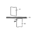
- FIG. 14 is a schematic side view of the conventional method for manufacturing a laminated member described in Patent Document 1, and shows the positional relationship between the upper blade 61, the lower blade 62, and the laminated amorphous ribbon 63. .
- the clearance is 4 ⁇ m or less as an appropriate value for the thickness of one amorphous ribbon 63, 25 ⁇ m, and 3 ⁇ m in this example.
- the upper blade 61 is lowered and cut at a cutting speed of 0.2 m / sec or more.
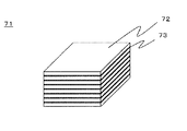
- FIG. 15 is a schematic perspective view showing a method of manufacturing the conventional laminate 71 described in Patent Document 2.
- the entire surface of the laminated soft magnetic metal ribbons 72 is bonded with a thermosetting resin 73 to form a laminate 71, which is punched.
- thermosetting resin 73 for adhesion exists between the layers of the soft magnetic metal ribbon 72, the amorphous ribbon in the stacking direction is occupied. There is a problem that the volume factor is lowered and the magnetic properties are lowered.
- the present invention solves the conventional problems, and provides a laminated member that does not cause a shape defect such as a crack or a chip in a thin strip or a deterioration in characteristics, a manufacturing method thereof, a laminated body, and a motor using them.
- the purpose is to do.
- a laminated member obtained by laminating a plurality of alloy ribbons, and a laminated member including a fracture surface is used on the side surface.
- the laminated amorphous ribbons when the laminated amorphous ribbons are processed into shapes, they do not slide between layers, cracks, chips, etc., and shape accuracy does not deteriorate, and there is no adhesive between the layers. Since the space factor does not decrease, the laminated member can be processed with good dimensional accuracy and without causing deterioration of characteristics.
- the laminated member As described above, according to the laminated member, the manufacturing method thereof, the laminated body, and the motor of the present invention, high productivity is achieved without causing shape defects such as cracks and chips in the thin strip of the laminated member and deterioration of characteristics. Can be processed, and motor characteristics using the same can be improved.
- FIG. 1A is a cross-sectional view showing the steps of a method for laminating and fixing an amorphous ribbon according to Embodiment 1 of the present invention.
- FIG. 1B is a cross-sectional view showing the steps of the method for laminating and fixing an amorphous ribbon according to Embodiment 1 of the present invention.
- FIG. 1C is a cross-sectional view showing the steps of the amorphous ribbon laminating and fixing method according to Embodiment 1 of the present invention.
- FIG. 2A is a top view of the method for manufacturing the laminated member in Embodiment 1 of the present invention.
- FIG. 2B is a cross-sectional view taken along AA ′ in FIG. 2A.
- FIG. 3A is a schematic cross-sectional view before punching in the punching process of the processing member according to Embodiment 1 of the present invention.
- FIG. 3B is a cross-sectional view in the middle of punching after FIG. 3A.
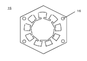
- FIG. 4A is a side view of the laminated member according to Embodiment 1 of the present invention.
- FIG. 4B is a top view of FIG. 4A.
- FIG. 5A is a cross-sectional view of the vicinity of the cut portion of the laminated member according to Embodiment 1 of the present invention.
- FIG. 5B is a front view of FIG. 5A.
- 6A is a cross-sectional view of a cut form of the cut surface of the uppermost amorphous ribbon in FIG.
- FIG. 6B is a front view of FIG. 6A.
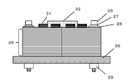
- FIG. 7A is a side view of the multilayer body according to Embodiment 1 of the present invention.
- FIG. 7B is a top view of FIG. 7A.
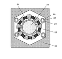
- FIG. 8A is a side view of the motor according to Embodiment 1 of the present invention.
- FIG. 8B is a top view of FIG. 8A.
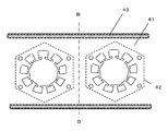
- FIG. 9A is a top view of an amorphous ribbon in a schematic diagram of a method for manufacturing a laminated member in Embodiment 2 of the present invention.
- FIG. 9B is a cross-sectional view taken along the line B-B ′ of FIG. 9A.
- FIG. 10A is a top view of an amorphous ribbon in a schematic diagram of a method for manufacturing a laminated member according to Embodiment 3 of the present invention.
- FIG. 10B is a cross-sectional view taken along the line C-C ′ of FIG. 10A.
- FIG. 11 is a schematic diagram of the upper surface of the method for manufacturing a laminated member in the fourth embodiment of the present invention.
- FIG. 12A is a cross-sectional view of a schematic diagram of a shearing process in the fourth embodiment of the present invention. 12B is a side view of FIG. 12A.
- FIG. 13A is a cross-sectional view of a schematic view in the vicinity of a cut surface of a processing member according to Embodiment 4 of the present invention.
- FIG. 13B is a front view of FIG. 13A.
- FIG. 14 is a schematic side view of a conventional method for manufacturing a laminated member described in Patent Document 1.
- FIG. 15 is a schematic perspective view
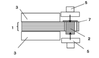
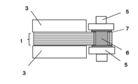
- FIGS. 1A to 1C are schematic cross-sectional views showing the steps of the method for laminating and fixing the amorphous ribbon 7 in the first embodiment of the present invention. Specifically, a metal fastening mechanism using a caulking structure is shown.
- the caulking is a method of fixing the amorphous ribbon group 1 by passing the rivet material 2 through the hole 4 provided in the amorphous ribbon group 1 and spreading both ends of the rivet material 2 from the hole 4. .
- the purpose is to fix the laminated amorphous ribbons 7 together.
- an amorphous ribbon group 1 in which amorphous ribbons 7 are laminated an amorphous ribbon group 1 in which amorphous ribbons 7 are laminated, a rivet material 2, a pressing mechanism 3 for sandwiching the amorphous ribbon group 1 from above and below, and a rivet material 2 And a hole 4 for insertion.
- the amorphous ribbon 7 constituting the amorphous ribbon group 1 is an iron-based alloy having a plate thickness of 10 ⁇ m to 60 ⁇ m.
- the amorphous ribbon 7 is manufactured by quenching by pouring molten iron-based alloy onto the surface of a rotating cooling drum and drawing it into a ribbon shape.
- the amorphous ribbon 7 is an amorphous magnetic material, but its magnetic properties are improved when it is crystallized by heat treatment.
- a rivet material 2 is inserted into the hole 4 of the amorphous ribbon group 1 in the direction of the arrow.
- the amorphous ribbon group 1 is fixed by the presser mechanism 3, and the inserted rivet material 2 is compressed by the compression mechanism 5 from the direction of the arrow.
- the rivet material 2 is processed into a metal fastening part 6 having a flange formed vertically.
- the compression may be a height regulation that makes the caulking height constant, or a pressure regulation that makes the caulking pressure constant.
- the metal fastening mechanism may be eyelets. Eyelets are sometimes called grommets or eyelets.
- FIG. 2A and 2B show a method for fixing the amorphous ribbon group 1 using the above fixing method.
- 2A is a top view of the amorphous ribbon group 1.
- FIG. 2B is a cross-sectional view taken along the line AA ′ of FIG. 2A.
- FIG. 2A shows a planned position 8 that becomes the laminated member 15 after processing.
- the position of the hole 4 into which the metal fastening component 6 is inserted is outside the planned position 8 where the laminated member 15 is to be formed.
- metal fastening part 6 There are no particular restrictions on the material of the metal fastening part 6.
- An iron-based material may be used, but it is preferable to use a non-ferrous metal such as copper or aluminum because it is easy to process and can secure necessary strength.
- the laminated amorphous ribbon 7 is caulked with the metal fastening part 6.
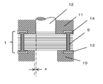
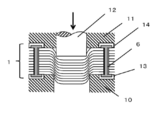
- FIGS. 3A and 3B are schematic cross-sectional views of a process of punching the amorphous ribbon group 1 composed of the laminated amorphous ribbons 7 and manufacturing the laminated member 15.
- FIG. 3A is a schematic cross-sectional view before punching, and FIG.
- the amorphous ribbon group 1 is placed on the die 10 and fixed with the presser plate 11, and the punch 12 is placed on the upper surface of the amorphous ribbon group 1. Since the flange of the metal fastening part 6 protrudes up and down, the die 10 and the holding plate 11 are each provided with a relief hole 13 and a relief hole 14, and an amorphous thin film so that the flange of the metal fastening part 6 enters therein.
- Band group 1 is installed.
- the clearance a between the punch 12 and the die 10 is set to 5 to 10% of the thickness of the amorphous ribbon 7 in accordance with the basics of press punching. Since the thickness of the amorphous ribbon 7 is 10 to 60 ⁇ m, the clearance a is 6 ⁇ m at the maximum.
- the number of laminated amorphous ribbons 7 is two or more in order to increase productivity, but the maximum number of layers was 25 layers that could be punched without causing shape defects.
- the punch 12 is lowered in the direction of the arrow at a maximum punching speed of 0.25 m / sec.
- the amorphous ribbon group 1 fixed by the die 10 and the holding plate 11 is deformed into a convex shape as shown in FIG. 3B.
- the amorphous ribbon group 1 is fixed to each other by the metal fastening part 6, so that the amorphous ribbons 7 do not slide to each other and are not drawn downward. .
- the amorphous ribbon 7 is cut.
- the fixing position by the metal fastening component 6 is not matched with the cutting processed part by punching. If a different material from the amorphous ribbon 7 is punched at the same time, not only the fixing by the die 10 and the holding plate 11 becomes structurally unstable, but the punch 12 receives an irregular force due to deformation of the composite material. The life is shortened. As a result, the laminated member 15 shown in FIGS. 4A and 4B below is manufactured.
- FIG. 4A and 4B are schematic views of the laminated member 15 obtained by cutting the amorphous ribbon group 1.
- FIG. 4A is a side view and FIG. 4B is a top view.
- FIG. 4B there is a bolt fastening hole 16.
- the bolt fastening hole 16 is a hole into which a bolt for laminating and fixing the laminated member 15 is inserted.
- the bolt fastening hole 16 is formed in the laminated member 15 at the time of the above processing.
- FIGS. 4A and 4B are schematic views near the cut portion of the laminated member 15 in FIGS. 4A and 4B, FIG. 5A is a cross-sectional view, and FIG. 5B is a front view.
- FIG. 6A and FIG. 6B are enlarged schematic views of a fractured form of the cut surface of the uppermost amorphous ribbon 17 in FIG. 5A and FIG. 5B.
- 6A is a cross-sectional view
- FIG. 6B is a front view.
- the cut surface consists of four forms: a sag 21, a shear surface 22, a fracture surface 23, and a burr 24 from the top.
- the characteristics of each shape are that the sagging 21 is a smooth R-shaped convex part, the shearing surface 22 is a shape with gloss and vertical streaks, the fractured surface 23 is a shape stripped of material, or the surface has multiple types of irregularities.
- a certain shape, the burr 24, is a portion where the fracture surface 23 protrudes partially downward, and has a jagged shape when viewed from the front. Apart from the proportions of the four forms, these are similar in shape to those commonly found in sheet metal stamped with a press.
- the shear cutting in Patent Document 1 is cutting by shearing. Therefore, at least the fracture surface 23 showing a mark that has been peeled or torn off due to a tensile fracture does not appear.
- a sag 21 and a shearing surface 22 are formed.
- the proportion of the shear surface 22 of the amorphous ribbon 7 decreases and the fracture surface 23 increases as it progresses to the lower layer.
- Most of the amorphous ribbon 7 below the center has a fracture surface 23.
- the burr 24 is generated below the fracture surface 23. If the cutting conditions such as the clearance b and the fixing force of the presser plate 11 are appropriate, the burr 24 is rubbed to the amorphous ribbon 7 immediately below, and the amorphous ribbons 7 are joined together.
- the laminated member 15 obtained in this way can also be handled as an integral object without performing interlayer adhesion separately. Moreover, since the interlayer of the amorphous ribbon 7 is blocked, it is possible to prevent foreign matters from being mixed into the interlayer.
- the maximum value of the uneven clearance b on the cut surface in FIG. 5A is determined by the clearance in the mold.
- the maximum value of the clearance b in FIG. 5A is 9 ⁇ m.
- 7A and 7B are a side view and a top view of a laminate 25 in which a plurality of laminate members 15 are laminated, respectively.
- the laminated body 25 is fastened by a nut 29 through a spring washer 27 and a washer 28 by inserting a bolt 26 into the bolt fastening hole 16.
- a nut 29 through a spring washer 27 and a washer 28 by inserting a bolt 26 into the bolt fastening hole 16.
- the cut surface of the laminated member 15 has irregularities, but by periodically repeating the irregularity shape by laminating, various phenomena due to irregularities in the lamination height direction are averaged. It becomes.
- the laminated member 15 is formed by laminating the amorphous ribbons 7, it is crystallized by an appropriate heat treatment, and the magnetic properties are improved. However, since the amorphous ribbon 7 becomes brittle when heat-treated, it must be processed into a predetermined shape before the heat treatment.
- the laminated member 15 that is a laminated body of the amorphous ribbon 7 may be heat-treated, and then the laminated member 15 may be laminated and fastened with bolts 26 as shown in FIGS. 7A and 7B.
- the laminated member 15, which is a laminated body of the amorphous ribbon 7 may be laminated and heat treated in a state of being fastened with the bolts 26.
- the heat treatment is performed, at least the end surface of the laminated member 15 is colored and visually recognized oxide is formed.
- the soft magnetic characteristics are greatly improved and the motor characteristics are also improved.
- the laminated body 25 is obtained by laminating a plurality of laminated members 15, the laminated end faces periodically repeat the cross-sectional forms shown in FIGS. 5A and 5B in the laminating direction regardless of the presence or absence of heat treatment.
- FIG. 8A and 8B are diagrams showing a motor using the laminated body 25.
- FIG. FIG. 8A is a side view of the motor
- FIG. 8B is a top view of the motor.
- the nut 29 is removed from the state of FIG. 7A and FIG.
- a winding 31 is applied to the laminated body 25 to form a stator.
- a rotor 32 is installed on the inner diameter part of the laminate 25. If the winding 31 is energized in this state, it is driven as a motor.
- end surfaces are bonded to each other, they can be handled as an integrated object, which has the effect of increasing the productivity of the subsequent process.
- FIG. 9A and 9B are schematic views of a method for manufacturing the laminated member 15 according to Embodiment 2 of the present invention.
- 9A is a top view of the amorphous ribbon 41
- FIG. 9B is a cross-sectional view taken along the line BB ′ of FIG. 9A. Matters not described are the same as those in the first embodiment.
- 9A and 9B differ from the first embodiment in that the adhesive 43 does not cover the planned punching position 42 shown by the punching shape of the laminated member 15 in the vicinity of both side surfaces of the amorphous ribbon 41. It was applied to. After the application, it is laminated, dried and fixed to form a processing member 44.
- FIG. 10A and 10B are schematic views of the method for manufacturing the laminated member 15 according to Embodiment 3 of the present invention.
- FIG. 10A is a top view of the laminated amorphous ribbon 45
- FIG. 10B is the laminated amorphous film of FIG. 10A.
- 6 is a cross-sectional view taken along CC ′ of the ribbon 45.
- FIG. Matters not described are the same as in the first and second embodiments.
- FIGS. 9A and 9B differ from FIGS. 9A and 9B in the second embodiment in that an adhesive 46 is applied to the outside of the laminated end face of the laminated amorphous ribbon 45, and then dried and fixed.
- the processing member 47 is used.
- a fixed processing member 47 can be provided without creating a gap between the layers of the amorphous ribbon 45. Since there is no gap between the layers, the amorphous ribbon 45 does not bend, so that the cutting process can be performed with higher accuracy.
- FIG. 11 is a diagram illustrating a method for manufacturing the laminated member 15 according to the fourth embodiment of the present invention.
- FIG. 11 is a plan view of the laminated amorphous ribbon 51.
- the laminated amorphous ribbon 51, the planned position 52 to be the laminated member 15, and the position of the hole 4 into which the metal fastening part for fixing the amorphous ribbon 51 in the lamination direction is inserted are displayed. Matters not described are the same as in the first to third embodiments.
- FIG. 11 differs from FIG. 2A of the first embodiment in that the position of the hole 4 fixed by the metal fastening part 53 is inside the planned punching position 52 of the laminated member 15.
- the method of fixing the laminated amorphous ribbon 7 with the metal fastening part is the same as the method described in FIGS. 1A to 2B of the first embodiment.
- the positions of the holes 4 that are fixed positions are two places in the laminated member 15 that is a product.
- the punched laminated member 15 is not in close contact with the entire interlayer, but can be held and handled as a single piece by fixing at least two locations. Since the obtained laminated member 15 can be handled as an integral object, it can be efficiently handled between processes in a small amount of time. In the fixing at one place, the amorphous ribbon rotates or the handleability as an integral object is deteriorated. If the number of fixed positions is large, it becomes hard as a single body, but on the other hand, it becomes a magnetic path obstacle, and there is also a disadvantage that the magnetic properties are deteriorated. Therefore, the position and size of the metal fastening part 53 need to be optimized.
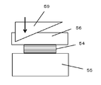
- FIG. 12A is a cross-sectional view of the process of cutting the processing member 54 made of the laminated amorphous ribbon 51 of FIG. 11 by shearing, as seen from the D-D ′ plane of FIG. 12B is a side view of FIG. 12B.
- the processing member 54 is fixed on the die 55 with a presser plate 56.
- the metal fastening part 53 is installed so that the flange of the metal fastening part 53 enters the escape hole 57 and the escape hole 58.
- a shear blade 59 with an inclination angle is pushed down in the direction indicated by the arrow and sheared. As a result, the shear force can be greatly reduced. Therefore, as compared with the punching in FIGS. 3A and 3B of the first embodiment, the force acting to slide the amorphous ribbon 51 between the layers is reduced, so that the processing can be performed even if the clearance c is reduced to 2 ⁇ m or less. .
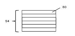
- FIG. 13A is a schematic cross-sectional view of the cut processing member 54 in the vicinity of the cut surface.
- FIG. 13B is a front view of FIG. 13A. Since the shearing process is performed by the shear blade 59, unlike FIG. 5A of the first embodiment, the unevenness of the end face of the cut surface in FIG.
- the shear plane 60 accounted for 75% or more, and preferably 80% or more. Since the dimensional accuracy of the cut surface is good, the gap with the rotor 32 can be reduced when used in a motor, so that the motor efficiency is stabilized and further improved.
- Embodiments 1 to 4 can be combined.
- the laminated member of the present invention, the laminated body, and the manufacturing method thereof can be applied to uses of magnetic electronic components such as transformers in addition to motors.
Landscapes
- Engineering & Computer Science (AREA)
- Power Engineering (AREA)
- Mechanical Engineering (AREA)
- Manufacturing & Machinery (AREA)
- Manufacture Of Motors, Generators (AREA)
- Manufacturing Cores, Coils, And Magnets (AREA)
- Iron Core Of Rotating Electric Machines (AREA)
Abstract
Un élément stratifié comprenant une pluralité de rubans d'alliage stratifiés ensemble comprend une surface latérale dans laquelle est utilisé un élément stratifié ayant une surface de fracture. Un corps stratifié comprend un stratifié des éléments stratifiés. Un moteur comprend le corps stratifié dans le noyau. Un procédé de fabrication d'élément stratifié comprend : une étape de fixation consistant à stratifier une pluralité de rubans amorphes et à fixer des parties de couches des rubans amorphes stratifiés les unes aux autres ; et une étape de poinçonnage consistant à poinçonner un élément stratifié en découpant un groupe des rubans amorphes stratifiés au niveau de parties autres qu'une partie fixe qui a été fixée.
Priority Applications (4)
| Application Number | Priority Date | Filing Date | Title |
|---|---|---|---|
| EP18758042.8A EP3588520A4 (fr) | 2017-02-24 | 2018-02-08 | Élément stratifié, son procédé de fabrication, corps stratifié et moteur |
| US16/325,373 US11225049B2 (en) | 2017-02-24 | 2018-02-08 | Laminated member, laminated body, and motor |
| CN201880003265.3A CN109643602B (zh) | 2017-02-24 | 2018-02-08 | 层叠部件及其制造方法、层叠体以及电机 |
| JP2018541449A JP6462967B1 (ja) | 2017-02-24 | 2018-02-08 | 積層部材とその製造方法と、積層体およびモータ |
Applications Claiming Priority (2)
| Application Number | Priority Date | Filing Date | Title |
|---|---|---|---|
| JP2017-033100 | 2017-02-24 | ||
| JP2017033100 | 2017-02-24 |
Publications (1)
| Publication Number | Publication Date |
|---|---|
| WO2018155206A1 true WO2018155206A1 (fr) | 2018-08-30 |
Family
ID=63253309
Family Applications (1)
| Application Number | Title | Priority Date | Filing Date |
|---|---|---|---|
| PCT/JP2018/004364 Ceased WO2018155206A1 (fr) | 2017-02-24 | 2018-02-08 | Élément stratifié, son procédé de fabrication, corps stratifié et moteur |
Country Status (5)
| Country | Link |
|---|---|
| US (1) | US11225049B2 (fr) |
| EP (1) | EP3588520A4 (fr) |
| JP (1) | JP6462967B1 (fr) |
| CN (1) | CN109643602B (fr) |
| WO (1) | WO2018155206A1 (fr) |
Cited By (2)
| Publication number | Priority date | Publication date | Assignee | Title |
|---|---|---|---|---|
| WO2020179399A1 (fr) | 2019-03-01 | 2020-09-10 | 日立金属株式会社 | Bande mince de métal amorphe, noyau stratifié, et procédé de poinçonnage de ruban mince de métal amorphe |
| EP4032698A1 (fr) | 2021-01-26 | 2022-07-27 | Hitachi Metals, Ltd. | Noyau de stratification amorphe pour moteur, procédé de fabrication d'un noyau de stratification amorphe pour moteur, et ruban d'alliage amorphe pour moteur |
Families Citing this family (4)
| Publication number | Priority date | Publication date | Assignee | Title |
|---|---|---|---|---|
| JP6633039B2 (ja) * | 2017-09-20 | 2020-01-22 | 本田技研工業株式会社 | ステータ及びその製造方法と、ステータ用コア部材製造装置 |
| JP7136821B2 (ja) * | 2020-02-17 | 2022-09-13 | アピックヤマダ株式会社 | 順送プレス加工方法 |
| JPWO2022054722A1 (fr) * | 2020-09-09 | 2022-03-17 | ||
| WO2022054725A1 (fr) * | 2020-09-09 | 2022-03-17 | アルプスアルパイン株式会社 | Noyau magnétique, et composant magnétique |
Citations (4)
| Publication number | Priority date | Publication date | Assignee | Title |
|---|---|---|---|---|
| JPS55156623A (en) * | 1979-05-23 | 1980-12-05 | Shinko Electric Co Ltd | Blanking method for overlapped double sheets for iron core of electrical machinery and apparatus |
| JPH09192919A (ja) * | 1996-01-18 | 1997-07-29 | Daihen Corp | アモルファス磁性合金ストリップの切断装置 |
| JP2008262944A (ja) * | 2007-04-10 | 2008-10-30 | Hitachi Metals Ltd | 積層体コアおよびその製造方法 |
| JP2015013612A (ja) * | 2013-07-08 | 2015-01-22 | コイト電工株式会社 | 車両用座席装置 |
Family Cites Families (14)
| Publication number | Priority date | Publication date | Assignee | Title |
|---|---|---|---|---|
| US4783983A (en) * | 1986-11-12 | 1988-11-15 | Mandayam Narasimhan | Method and apparatus for amorphous metal slitting |
| JPH0379215A (ja) | 1989-08-17 | 1991-04-04 | Fuji Electric Co Ltd | 積層アモルファス合金薄帯の切断方法 |
| JPH10241980A (ja) * | 1997-02-27 | 1998-09-11 | Takaoka Electric Mfg Co Ltd | アモルファス鉄心の製造方法 |
| US6737784B2 (en) | 2000-10-16 | 2004-05-18 | Scott M. Lindquist | Laminated amorphous metal component for an electric machine |
| JP2003153503A (ja) | 2001-11-08 | 2003-05-23 | Matsushita Electric Ind Co Ltd | 電動機鉄心の製造方法 |
| JP2003304654A (ja) * | 2002-04-08 | 2003-10-24 | Mitsui High Tec Inc | 積層鉄心 |
| JP2008213410A (ja) | 2007-03-07 | 2008-09-18 | Hitachi Metals Ltd | 積層板、および積層体の製造方法 |
| JP4466671B2 (ja) * | 2007-03-28 | 2010-05-26 | 株式会社日立製作所 | 誘導機 |
| JP5630150B2 (ja) * | 2010-08-31 | 2014-11-26 | トヨタ紡織株式会社 | パンチング装置 |
| AU2011344083B2 (en) | 2010-12-13 | 2016-08-11 | Radam Motors, Llc | Stator used in an electrical motor or generator with low loss magnetic material and method of manufacturing a stator |
| JP6307285B2 (ja) * | 2014-01-22 | 2018-04-04 | 株式会社三井ハイテック | 鉄心片の打ち抜き方法 |
| JP6401466B2 (ja) | 2014-03-10 | 2018-10-10 | 株式会社三井ハイテック | 積層鉄心及びその製造方法 |
| JP6438731B2 (ja) | 2014-10-21 | 2018-12-19 | 株式会社三井ハイテック | 打抜き方法及び打抜き装置並びに積層鉄心の製造方法 |
| JP6210058B2 (ja) * | 2014-12-26 | 2017-10-11 | Jfeスチール株式会社 | 積層鉄心用の打抜き加工方法及び積層鉄心の製造方法 |
-
2018
- 2018-02-08 US US16/325,373 patent/US11225049B2/en not_active Expired - Fee Related
- 2018-02-08 EP EP18758042.8A patent/EP3588520A4/fr not_active Withdrawn
- 2018-02-08 JP JP2018541449A patent/JP6462967B1/ja not_active Expired - Fee Related
- 2018-02-08 WO PCT/JP2018/004364 patent/WO2018155206A1/fr not_active Ceased
- 2018-02-08 CN CN201880003265.3A patent/CN109643602B/zh not_active Expired - Fee Related
Patent Citations (4)
| Publication number | Priority date | Publication date | Assignee | Title |
|---|---|---|---|---|
| JPS55156623A (en) * | 1979-05-23 | 1980-12-05 | Shinko Electric Co Ltd | Blanking method for overlapped double sheets for iron core of electrical machinery and apparatus |
| JPH09192919A (ja) * | 1996-01-18 | 1997-07-29 | Daihen Corp | アモルファス磁性合金ストリップの切断装置 |
| JP2008262944A (ja) * | 2007-04-10 | 2008-10-30 | Hitachi Metals Ltd | 積層体コアおよびその製造方法 |
| JP2015013612A (ja) * | 2013-07-08 | 2015-01-22 | コイト電工株式会社 | 車両用座席装置 |
Non-Patent Citations (1)
| Title |
|---|
| See also references of EP3588520A4 * |
Cited By (3)
| Publication number | Priority date | Publication date | Assignee | Title |
|---|---|---|---|---|
| WO2020179399A1 (fr) | 2019-03-01 | 2020-09-10 | 日立金属株式会社 | Bande mince de métal amorphe, noyau stratifié, et procédé de poinçonnage de ruban mince de métal amorphe |
| US11975377B2 (en) | 2019-03-01 | 2024-05-07 | Proterial, Ltd. | Amorphous metal thin strip, laminated core, and amorphous metal thin ribbon punching method |
| EP4032698A1 (fr) | 2021-01-26 | 2022-07-27 | Hitachi Metals, Ltd. | Noyau de stratification amorphe pour moteur, procédé de fabrication d'un noyau de stratification amorphe pour moteur, et ruban d'alliage amorphe pour moteur |
Also Published As
| Publication number | Publication date |
|---|---|
| US11225049B2 (en) | 2022-01-18 |
| CN109643602B (zh) | 2022-02-11 |
| US20190202175A1 (en) | 2019-07-04 |
| EP3588520A1 (fr) | 2020-01-01 |
| EP3588520A4 (fr) | 2020-01-01 |
| JPWO2018155206A1 (ja) | 2019-02-28 |
| JP6462967B1 (ja) | 2019-01-30 |
| CN109643602A (zh) | 2019-04-16 |
Similar Documents
| Publication | Publication Date | Title |
|---|---|---|
| JP6462967B1 (ja) | 積層部材とその製造方法と、積層体およびモータ | |
| US10797541B2 (en) | Magnetic plate laminate, manufacturing method therefor, and motor using this laminate | |
| RU2678115C1 (ru) | Способ обработки вырубкой многослойного железного сердечника и способ изготовления многослойного железного сердечника | |
| CN105703565B (zh) | 层压体及其制造方法以及叠片铁芯的制造方法 | |
| JP6587800B2 (ja) | 積層鉄心の製造方法 | |
| CN109311073B (zh) | 金属部件的冲裁方法和适用于这种冲裁方法的冲裁装置 | |
| JP2017011863A (ja) | モータ鉄心用積層電磁鋼板およびその製造方法 | |
| JP5285020B2 (ja) | 積層鉄心とその製造方法 | |
| US20190181700A1 (en) | Iron core and motor using iron core | |
| JP2019012777A (ja) | 無方向性電磁鋼板およびその製造方法 | |
| JP2020192583A (ja) | 積層部材の製造方法、積層部材、積層体、およびモータ | |
| JP7401428B2 (ja) | 金属部品を製造するための複層打抜き加工方法 | |
| US20210152061A1 (en) | Method of manufacturing stator, stator, and motor | |
| JP2000173815A (ja) | 積層鉄心用接着鋼板 | |
| JP3842146B2 (ja) | 積層鉄心の製造方法 | |
| JP7625887B2 (ja) | Fe基軟磁性非晶質合金の薄板、それを用いた積層鉄心および回転電機、並びにFe基軟磁性非晶質合金の薄板の製造方法 | |
| JPWO2018012599A1 (ja) | ローターコア鋼板及びその製造方法並びにローター | |
| JP2019161765A (ja) | 電磁鋼板 | |
| WO2024116815A1 (fr) | Procédé de fabrication d'un article en alliage métallique amorphe | |
| WO2024116811A1 (fr) | Procédé de fabrication de pièce d'alliage amorphe, procédé de fabrication de noyau de fer stratifié et noyau de fer stratifié | |
| JP2025111967A (ja) | せん断加工面を有する非晶質合金積層体 | |
| JP2019161766A (ja) | 電磁鋼板 | |
| JP2022037790A (ja) | モータコアの製造方法 | |
| CN1842956A (zh) | 用于磁悬浮车辆的定子叠片 | |
| JP2000343145A (ja) | ロータリーブランキング用ロール金型およびロータリーブランキング方法 |
Legal Events
| Date | Code | Title | Description |
|---|---|---|---|
| ENP | Entry into the national phase |
Ref document number: 2018541449 Country of ref document: JP Kind code of ref document: A |
|
| 121 | Ep: the epo has been informed by wipo that ep was designated in this application |
Ref document number: 18758042 Country of ref document: EP Kind code of ref document: A1 |
|
| NENP | Non-entry into the national phase |
Ref country code: DE |
|
| ENP | Entry into the national phase |
Ref document number: 2018758042 Country of ref document: EP Effective date: 20190924 |