WO2018155248A1 - Batterie secondaire à électrolyte non aqueux - Google Patents
Batterie secondaire à électrolyte non aqueux Download PDFInfo
- Publication number
- WO2018155248A1 WO2018155248A1 PCT/JP2018/004778 JP2018004778W WO2018155248A1 WO 2018155248 A1 WO2018155248 A1 WO 2018155248A1 JP 2018004778 W JP2018004778 W JP 2018004778W WO 2018155248 A1 WO2018155248 A1 WO 2018155248A1
- Authority
- WO
- WIPO (PCT)
- Prior art keywords
- positive electrode
- negative electrode
- electrode plate
- resin tape
- mixture layer
- Prior art date
- Legal status (The legal status is an assumption and is not a legal conclusion. Google has not performed a legal analysis and makes no representation as to the accuracy of the status listed.)
- Ceased
Links
Images
Classifications
-
- H—ELECTRICITY
- H01—ELECTRIC ELEMENTS
- H01M—PROCESSES OR MEANS, e.g. BATTERIES, FOR THE DIRECT CONVERSION OF CHEMICAL ENERGY INTO ELECTRICAL ENERGY
- H01M10/00—Secondary cells; Manufacture thereof
- H01M10/05—Accumulators with non-aqueous electrolyte
-
- H—ELECTRICITY
- H01—ELECTRIC ELEMENTS
- H01M—PROCESSES OR MEANS, e.g. BATTERIES, FOR THE DIRECT CONVERSION OF CHEMICAL ENERGY INTO ELECTRICAL ENERGY
- H01M10/00—Secondary cells; Manufacture thereof
- H01M10/05—Accumulators with non-aqueous electrolyte
- H01M10/058—Construction or manufacture
- H01M10/0587—Construction or manufacture of accumulators having only wound construction elements, i.e. wound positive electrodes, wound negative electrodes and wound separators
-
- Y—GENERAL TAGGING OF NEW TECHNOLOGICAL DEVELOPMENTS; GENERAL TAGGING OF CROSS-SECTIONAL TECHNOLOGIES SPANNING OVER SEVERAL SECTIONS OF THE IPC; TECHNICAL SUBJECTS COVERED BY FORMER USPC CROSS-REFERENCE ART COLLECTIONS [XRACs] AND DIGESTS
- Y02—TECHNOLOGIES OR APPLICATIONS FOR MITIGATION OR ADAPTATION AGAINST CLIMATE CHANGE
- Y02E—REDUCTION OF GREENHOUSE GAS [GHG] EMISSIONS, RELATED TO ENERGY GENERATION, TRANSMISSION OR DISTRIBUTION
- Y02E60/00—Enabling technologies; Technologies with a potential or indirect contribution to GHG emissions mitigation
- Y02E60/10—Energy storage using batteries
-
- Y—GENERAL TAGGING OF NEW TECHNOLOGICAL DEVELOPMENTS; GENERAL TAGGING OF CROSS-SECTIONAL TECHNOLOGIES SPANNING OVER SEVERAL SECTIONS OF THE IPC; TECHNICAL SUBJECTS COVERED BY FORMER USPC CROSS-REFERENCE ART COLLECTIONS [XRACs] AND DIGESTS
- Y02—TECHNOLOGIES OR APPLICATIONS FOR MITIGATION OR ADAPTATION AGAINST CLIMATE CHANGE
- Y02P—CLIMATE CHANGE MITIGATION TECHNOLOGIES IN THE PRODUCTION OR PROCESSING OF GOODS
- Y02P70/00—Climate change mitigation technologies in the production process for final industrial or consumer products
- Y02P70/50—Manufacturing or production processes characterised by the final manufactured product
Definitions
- the present invention relates to a nonaqueous electrolyte secondary battery having a flat wound electrode body.
- Non-aqueous electrolyte secondary batteries are widely used as driving power sources for portable electronic devices such as smartphones, tablet computers, notebook computers, and portable music players.
- portable electronic devices such as smartphones, tablet computers, notebook computers, and portable music players.
- a pouch-type non-aqueous electrolyte secondary battery using a pouch exterior body made of a laminate sheet as the exterior body is suitable.
- a flat wound electrode body is used for a pouch-type nonaqueous electrolyte secondary battery.
- the wound electrode body is produced by winding a plate group consisting of a positive electrode plate, a negative electrode plate, and a separator interposed therebetween in a flat shape along the core axis.
- curved portions are formed in which the electrode plate group is convexly curved outward from the electrode body.
- a non-aqueous electrolyte secondary battery is designed such that the ratio of the charge capacity of the negative electrode to the charge capacity of the positive electrode (positive / negative electrode capacity ratio) is greater than 1. Thereby, precipitation of lithium on the negative electrode during charging is prevented.
- the design value of the positive / negative electrode capacity ratio is determined based on the amount of active material per unit area of each of the positive electrode plate and the negative electrode plate. However, in the curved portion of the flat electrode body, since the outer electrode plate wraps the inner electrode plate, the outer electrode plate has a larger occupied volume in the bent portion.
- the positive / negative electrode capacity ratio between the outer surface of the negative electrode plate (the outer surface in the radial direction of the electrode body) and the inner surface of the winding electrode of the positive electrode plate (the inner surface in the radial direction of the electrode body) is smaller than the design value. End up.
- the difference between the positive and negative electrode capacity ratios as described above becomes larger toward the inner peripheral side of the electrode body. Therefore, the negative electrode may be excessively charged in the portion closest to the winding start side in the positive and negative electrode facing portions in the curved portion. Such a problem hardly occurs when the design value of the positive / negative electrode capacity ratio is sufficiently large.
- it is desirable to reduce the positive / negative electrode capacity ratio as much as possible in order to increase the capacity of the non-aqueous electrolyte secondary battery means for solving the above-mentioned problems have been studied.
- Patent Document 1 discloses that lithium deposition on the negative electrode is prevented by sticking an insulating resin tape to the inner surface of the winding portion of the positive electrode plate that is curved on the most winding start side.
- Patent Document 2 discloses a battery in which a portion on the innermost periphery of the curved portion of the facing portions of the positive and negative electrode active material layers does not participate in charging / discharging. Specifically, as in Patent Document 1, it is disclosed that an insulating resin tape is adhered to the wound inner surface of the portion of the positive electrode plate that is curved on the most winding start side.
- Patent Document 1 describes that the positive electrode core body is prevented from being damaged by sticking a resin tape to the positive electrode plate. However, the effect is due to the curvature of the curved portion being reduced by the application of the resin tape. In any of Patent Documents 1 and 2, no consideration is given to the loss of flexibility of the positive electrode plate due to sticking of the resin tape.
- the present invention has been made in view of the above, and an object of the present invention is to prevent local overcharge of the negative electrode in the curved portion of the flat electrode body and to suppress cracking of the positive electrode core in the curved portion. .
- a non-aqueous electrolyte secondary battery is a flat electrode in which a positive electrode plate, a negative electrode plate, and an electrode plate group having a separator interposed therebetween are wound.
- the positive electrode plate has a positive electrode core and a positive electrode mixture layer formed on the surface thereof
- the negative electrode plate has a negative electrode core and a negative electrode mixture layer formed on the surface thereof.
- the electrode body has curved portions where the electrode plate group is curved at both ends in the major axis direction of the cross section perpendicular to the winding axis.
- the resin tape is stuck to the part arrange
- the resin tape includes an adhesive layer and a base material layer that does not transmit lithium ions.
- the adhesive strength of the resin tape to the positive electrode mixture layer is 0.1 N / cm or more and 2 N / cm or less.
- local overcharge of the negative electrode in the curved portion of the flat electrode body can be prevented, and cracks in the positive electrode core in the curved portion can be suppressed.
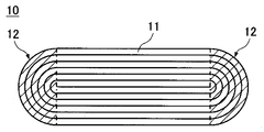
- FIG. 1 is a schematic cross-sectional view of a flat electrode body according to an embodiment.
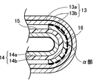
- FIG. 2 is an enlarged view of a main part of the bending portion of FIG.
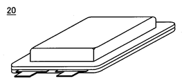
- FIG. 3 is a perspective view of the nonaqueous electrolyte secondary battery according to the example.
- FIGS. 1 and 2 schematically showing a cross section perpendicular to the winding axis of a flat electrode body.
- the electrode body 10 can be produced, for example, by winding the positive electrode plate 13 and the negative electrode plate 14 via a separator 15 and forming the wound electrode body into a flat shape by pressing.
- the cross section perpendicular to the winding axis of the flat electrode body 10 has a pair of electrode plates 11 in which a positive electrode plate 13, a negative electrode plate 14, and a separator 15 are stacked. It has a structure in which layers are stacked sequentially from the inner side to the outer side (radially outer side). At both ends in the major axis direction of the cross section, curved portions 12 where the electrode plate group 11 is curved are formed.
- the resin tape 16 is affixed to the part (alpha part shown with the dotted line of FIG. 2) arrange
- the resin tape 16 is preferably attached so as to cover the entire range of the ⁇ portion, and a part of the resin tape 16 may be attached so as to exceed the ⁇ portion.
- the position where the resin tape 16 is attached is not limited to the ⁇ part, and the resin tape may also be attached to the surface of the positive electrode mixture layer 13b outside the ⁇ part. However, if the resin tape 16 is attached to the ⁇ portion, local overcharge of the negative electrode can be effectively prevented. Since the range occupied by the ⁇ portion is extremely small compared to the total area of the front and back surfaces of the positive electrode plate, the influence of the resin tape 16 on the ⁇ portion on the battery capacity is small.
- the positive electrode mixture layer 13b is formed on both surfaces of the positive electrode core body 13a.
- the negative electrode mixture layer 14b is disposed so as to face the positive electrode mixture layer 13b with the separator 15 interposed therebetween. Since the positive electrode plate 13 does not exist on the innermost winding side of the negative electrode plate 14, the negative electrode mixture layer 14 b is not formed on the inner surface of the innermost negative electrode core 14 a of the negative electrode plate 14.
- the illustration of the separator 15 existing inside the innermost periphery of the negative electrode plate 14 is omitted.
- the resin tape includes at least two layers of a base material layer that does not transmit lithium ions in the non-aqueous electrolyte and an adhesive layer.
- a base material layer that does not transmit lithium ions By including the base material layer that does not transmit lithium ions, the charge / discharge reaction does not occur in the opposite portion of the positive and negative electrodes in the ⁇ portion, thereby preventing local overcharge of the negative electrode.
- any resin film that can stably exist without transmitting lithium ions in the nonaqueous electrolyte can be used without limitation.
- the resin material used for the base material layer include polyethylene, polypropylene, polyethylene terephthalate, polyvinyl alcohol, and polyimide.
- the thickness of a base material layer is not specifically limited, Since the softness
- the adhesive strength of the resin tape to the positive electrode mixture layer is preferably 2 N / cm or less. If the adhesive strength of the resin tape to the positive electrode mixture layer is 2 N / cm or less, a part of the adhesive layer peels off from the positive electrode mixture layer when the portion where the resin tape is attached is curved with a large curvature. Fine cracks are generated in the positive electrode mixture layer. Thereby, the softness
- the adhesive strength of the resin tape to the positive electrode mixture layer 13b is preferably 0.1 N / cm or more.
- the pressure-sensitive adhesive used for the pressure-sensitive adhesive layer of the resin tape examples include, but are not limited to, acrylic and rubber-based pressure-sensitive adhesives.
- the adhesive strength of the resin tape to the positive electrode mixture layer can be adjusted by changing the components of the adhesive and the thickness of the adhesive layer. For example, if the thickness of the pressure-sensitive adhesive layer is 3 ⁇ m or less, the amount of the pressure-sensitive adhesive penetrating into the positive electrode mixture layer can be suppressed. Therefore, the adhesive force of the resin tape to the positive electrode mixture layer can be easily adjusted to 2 N / cm or less. Can do. Since the resin tape needs to maintain the state of being stuck to the positive electrode mixture layer until the electrode plate group is wound, the thickness of the pressure-sensitive adhesive layer is preferably 0.1 ⁇ m or more.
- the mixture layer can be formed by applying and drying a mixture slurry prepared by kneading an active material together with a binder in a dispersion medium on a core. The dried mixture layer is compressed to a predetermined thickness. A conductive agent and a thickener can be added to the mixture slurry as necessary.
- a metal foil is preferably used for the core, an aluminum foil is preferably used for the positive electrode core, and a copper foil is preferably used for the negative electrode core. Both aluminum foil and copper foil can contain a trace amount of different metals.
- a lithium transition metal composite oxide capable of reversibly occluding and releasing lithium ions
- the lithium transition metal composite oxide include general formula LiMO 2 (M is at least one of Co, Ni and Mn), LiMn 2 O 4 and LiFePO 4 . These can be used individually by 1 type or in mixture of 2 or more types, At least 1 chosen from the group which consists of Al, Ti, Mg, and Zr can be added or substituted with a transition metal element.
- carbon materials such as artificial graphite, natural graphite, non-graphitizable carbon, and graphitizable carbon that can reversibly occlude and release lithium ions can be used. Further, silicon and tin, oxides thereof, and the like can also be used. These can be used individually by 1 type or in mixture of 2 or more types.
- a microporous film made of polyolefin such as polyethylene or polypropylene can be used as the separator.
- a separator in which a plurality of microporous films having different compositions are stacked can be used.
- a laminated separator it is preferable to adopt a three-layer structure in which a layer mainly composed of polyethylene having a low melting point is used as an intermediate layer and a layer mainly composed of polypropylene having excellent oxidation resistance is used as a surface layer.
- the intermediate layer mainly composed of polyethylene exhibits a shutdown function that closes the separator and cuts off the current between the positive and negative electrodes when the battery temperature rises.
- inorganic particles such as aluminum oxide (Al 2 O 3 ), titanium oxide (TiO 2 ), and silicon oxide (SiO 2 ) can be added to the separator.
- inorganic particles can be carried in the separator and can be applied together with a binder on the separator surface.
- an aramid resin having excellent heat resistance can be applied to the separator surface.
- non-aqueous electrolyte a solution obtained by dissolving a lithium salt as an electrolyte salt in a non-aqueous solvent can be used.
- a non-aqueous solvent or a non-aqueous electrolyte using a gel polymer together with the non-aqueous solvent can be used.
- a cyclic carbonate, a chain carbonate, a cyclic carboxylic acid ester and a chain carboxylic acid ester can be used, and it is preferable to use a mixture of two or more.
- the cyclic carbonate include ethylene carbonate (EC), propylene carbonate (PC), and butylene carbonate (BC).
- a cyclic carbonate in which part of hydrogen is substituted with fluorine, such as fluoroethylene carbonate (FEC) can also be used.
- the chain carbonate include dimethyl carbonate (DMC), ethyl methyl carbonate (EMC), diethyl carbonate (DEC), and methyl propyl carbonate (MPC).
- Examples of cyclic carboxylic acid esters include ⁇ -butyrolactone ( ⁇ -BL) and ⁇ -valerolactone ( ⁇ -VL).
- Examples of chain carboxylic acid esters include methyl pivalate, ethyl pivalate, methyl isobutyrate and methyl pro Pionate is exemplified.
- LiPF 6 , LiBF 4 , LiCF 3 SO 3 , LiN (CF 3 SO 2 ) 2 , LiN (C 2 F 5 SO 2 ) 2 , LiN (CF 3 SO 2 ) (C 4 F 9 SO 2 ) LiC (CF 3 SO 2 ) 3 , LiC (C 2 F 5 SO 2 ) 3 , LiAsF 6 , LiClO 4 , Li 2 B 10 Cl 10 and Li 2 B 12 Cl 12 are exemplified.
- LiPF 6 is particularly preferable, and the concentration in the nonaqueous electrolyte is preferably 0.5 to 2.0 mol / L.
- Another lithium salt such as LiBF 4 can be mixed with LiPF 6 .
- a pouch-shaped exterior body made of a laminate sheet or a rectangular exterior can made of aluminum can be used.
- Preparation of positive electrode plate 95 parts by mass of lithium cobaltate (LiCoO 2 ) as the positive electrode active material, 2.5 parts by mass of carbon black as the conductive agent, and 2.5 parts by mass of polyvinylidene fluoride (PVdF) as the binder Mixed.
- the mixture was charged into N-methylpyrrolidone (NMP) as a dispersion medium and kneaded to prepare a positive electrode mixture slurry.
- NMP N-methylpyrrolidone
- the positive electrode mixture slurry was applied to both surfaces of a positive electrode core body made of an aluminum foil having a thickness of 12 ⁇ m and dried to form a positive electrode mixture layer. At this time, a positive electrode core exposed portion in which the positive electrode mixture layer was not formed was provided on a part of the positive electrode core.
- the positive electrode mixture layer after drying was compressed with a roller so as to have a packing density of 3.6 g / cm 3 and cut into a predetermined size. Finally, a positive electrode tab made of aluminum was joined to the exposed portion of the positive electrode core to produce a positive electrode plate.
- the dried negative electrode mixture layer was compressed with a roller so that the filling density was 1.6 g / cm 3 , and cut into a predetermined size. Finally, a negative electrode tab made of nickel was joined to the exposed portion of the negative electrode core body to prepare a negative electrode plate.
- An electrode plate group in which a positive electrode plate and a negative electrode plate are laminated via a separator made of a polyethylene microporous film having a thickness of 16 ⁇ m is wound, and the wound electrode body is formed by hot pressing to produce a flat electrode body.
- a resin tape was attached to a portion of the surface of the positive electrode mixture layer in the curved portion of the electrode body that is initially disposed on the curved portion.
- a polyolefin film having a thickness of 12 ⁇ m was used for the base layer of the resin tape.
- An acrylic pressure-sensitive adhesive was used for the pressure-sensitive adhesive layer of the resin tape, and its thickness was 3 ⁇ m.
- a non-aqueous solvent was prepared by mixing ethylene carbonate (EC) and methyl ethyl carbonate (MEC) in a volume ratio of 30:70.
- EC ethylene carbonate
- MEC methyl ethyl carbonate
- LiPF 6 lithium hexafluorophosphate
- VC vinylene carbonate
- the addition amount of vinylene carbonate was 1 mass% with respect to the nonaqueous electrolyte.
- the electrode body produced as described above was housed in a pouch exterior body made of a laminate sheet, and the outer peripheral portion of the pouch exterior body was heat-sealed except for the liquid injection port to prepare a pre-injection battery. After injecting a non-aqueous electrolyte into the pre-injection battery from the injection port, the injection port was heat-sealed to produce a non-aqueous electrolyte secondary battery 20 having a design capacity of 1000 mAh shown in FIG.
- Comparative Example 1 An electrode body and a non-aqueous electrolyte secondary battery according to Comparative Example 1 were produced in the same manner as in the example except that the thickness of the base layer of the resin tape was 20 ⁇ m and the thickness of the pressure-sensitive adhesive layer was 5 ⁇ m.
- Comparative Example 2 The electrode body according to Comparative Example 2 is the same as Comparative Example 1 except that a rubber-based adhesive mainly composed of styrene-butadiene rubber is used in place of the acrylic adhesive and the thickness of the adhesive layer is 10 ⁇ m. And the nonaqueous electrolyte secondary battery was produced.
- Comparative Example 3 An electrode body and a nonaqueous electrolyte secondary battery according to Comparative Example 3 were produced in the same manner as in the example except that the resin tape was not used.
- the adhesive strength of the resin tape to the positive electrode mixture layer was measured as follows. First, a size of 2 cm ⁇ 5 cm is cut out from the portion of the positive electrode plate where the positive electrode mixture layer is formed on both surfaces of the positive electrode core. A resin tape is attached to the surface of the cut out positive electrode plate. The portion of the resin tape that is not attached to the positive electrode plate is 20 mm / min. The resin tape was pulled until it was completely peeled off from the positive electrode plate, and the measured maximum load was defined as the adhesive strength (N / cm) of the resin tape to the positive electrode mixture layer. Table 1 shows the measurement results of the adhesive strength of the resin tapes used in Examples and Comparative Examples 1 and 2 with respect to the positive electrode mixture layer.
- the adhesive force of the resin tape of the example to the positive electrode mixture layer is smaller than the adhesive force of any of the resin tapes of Comparative Examples 1 and 2.
- the resin tape is attached.
- the formed portion is curved, a part of the resin tape is peeled from the positive electrode mixture layer, and a crack is generated in the positive electrode mixture layer.
- the adhesive force with respect to the positive mix layer of the resin tape of an Example is 1.5 N / cm, if the adhesive force is 2 N / cm or less, the effect similar to an Example will be exhibited.
- lithium deposition on the negative electrode facing the ⁇ portion was not confirmed after the charge / discharge cycle. Even if the adhesive strength of the resin tape is reduced, if the resin tape is securely fixed to the ⁇ part of the positive electrode plate during winding of the electrode plate group, the resin tape will not be misaligned during the charge / discharge cycle. Local overcharge can be prevented.
- the present invention local overcharge of the negative electrode in the curved portion of the electrode body can be prevented, and cracks in the positive electrode core can be suppressed.
- the capacity of the nonaqueous electrolyte secondary battery can be increased by reducing the positive / negative electrode capacity ratio. Therefore, the industrial applicability of the present invention is great.
Landscapes
- Engineering & Computer Science (AREA)
- Manufacturing & Machinery (AREA)
- Chemical & Material Sciences (AREA)
- Chemical Kinetics & Catalysis (AREA)
- Electrochemistry (AREA)
- General Chemical & Material Sciences (AREA)
- Secondary Cells (AREA)
Abstract
La présente invention a pour objet d'empêcher qu'une électrode négative dans une section coudée d'un corps d'électrode enroulée de forme plane ne soit localement surchargée, et d'empêcher qu'un corps de noyau d'électrode positive dans la section coudée ne se fissure. La batterie secondaire à électrolyte non aqueux selon un mode de la présente invention comprend : un corps d'électrode de forme plane dans lequel un groupe de plaques de pôle enroulé a une plaque d'électrode positive, une plaque d'électrode négative et un séparateur entreposé entre les plaques ; un électrolyte non aqueux ; et un corps extérieur. La plaque d'électrode positive a un corps de noyau d'électrode positive et une couche de mélange d'électrode positive formée à la surface de la plaque. La plaque d'électrode négative a un corps de noyau d'électrode négative et une couche de mélange d'électrode négative formée à la surface de la plaque. Dans une section transversale orthogonale aux axes d'enroulement, à chacune des parties d'extrémité dans la direction axiale majeure, le corps d'électrode a une section coudée dans laquelle le groupe de plaques de pôle est coudé. Parmi les surfaces sur la face interne d'enroulement de la couche de mélange d'électrode positive à l'intérieur de chacune des sections coudées, un ruban de résine est collé dans une section de la plaque d'électrode positive disposée la plus vers le début de l'enroulement. Le ruban de résine contient une couche adhésive et une couche de matériau de base qui ne transmet pas d'ions lithium. La force d'adhésion du ruban de résine par rapport à la couche de mélange d'électrode positive est comprise entre 0,1 N/cm et 2 N/cm inclus.
Priority Applications (3)
| Application Number | Priority Date | Filing Date | Title |
|---|---|---|---|
| CN201880009794.4A CN110249473B (zh) | 2017-02-24 | 2018-02-13 | 非水电解质二次电池 |
| US16/487,632 US20190386344A1 (en) | 2017-02-24 | 2018-02-13 | Nonaqueous electrolyte secondary battery |
| JP2019501237A JP7031653B2 (ja) | 2017-02-24 | 2018-02-13 | 非水電解質二次電池 |
Applications Claiming Priority (2)
| Application Number | Priority Date | Filing Date | Title |
|---|---|---|---|
| JP2017-033101 | 2017-02-24 | ||
| JP2017033101 | 2017-02-24 |
Publications (1)
| Publication Number | Publication Date |
|---|---|
| WO2018155248A1 true WO2018155248A1 (fr) | 2018-08-30 |
Family
ID=63253308
Family Applications (1)
| Application Number | Title | Priority Date | Filing Date |
|---|---|---|---|
| PCT/JP2018/004778 Ceased WO2018155248A1 (fr) | 2017-02-24 | 2018-02-13 | Batterie secondaire à électrolyte non aqueux |
Country Status (4)
| Country | Link |
|---|---|
| US (1) | US20190386344A1 (fr) |
| JP (1) | JP7031653B2 (fr) |
| CN (1) | CN110249473B (fr) |
| WO (1) | WO2018155248A1 (fr) |
Cited By (5)
| Publication number | Priority date | Publication date | Assignee | Title |
|---|---|---|---|---|
| JP2023516411A (ja) * | 2020-08-21 | 2023-04-19 | 寧徳時代新能源科技股▲分▼有限公司 | 電極組立体、電池セル、電池並びに電極組立体の製造方法及び装置 |
| KR20230084546A (ko) * | 2021-05-12 | 2023-06-13 | 컨템포러리 엠퍼렉스 테크놀로지 씨오., 리미티드 | 전극 조립체, 배터리 셀, 배터리 및 전기 장치 |
| JP2023536771A (ja) * | 2021-07-14 | 2023-08-30 | 寧徳時代新能源科技股▲分▼有限公司 | 電池アセンブリ、その加工方法及び装置、電池セル、電池並びに電力消費装置 |
| JP2024532538A (ja) * | 2021-09-10 | 2024-09-05 | 寧徳時代新能源科技股▲分▼有限公司 | 電極アセンブリ、電池セル、電池および電力消費装置 |
| JP2025511465A (ja) * | 2022-09-28 | 2025-04-16 | 寧徳時代新能源科技股▲分▼有限公司 | 捲回型の電極アセンブリ、電池セル、電池、電力消費装置と捲回機器 |
Families Citing this family (4)
| Publication number | Priority date | Publication date | Assignee | Title |
|---|---|---|---|---|
| WO2022222141A1 (fr) * | 2021-04-23 | 2022-10-27 | 宁德时代新能源科技股份有限公司 | Ensemble électrode, élément de batterie, batterie, et procédé et dispositif pour fabriquer l'ensemble électrode |
| WO2023123186A1 (fr) * | 2021-12-30 | 2023-07-06 | 宁德时代新能源科技股份有限公司 | Ensemble d'électrodes, batterie secondaire, module de batterie, bloc-batterie et dispositif électrique |
| CN114628795B (zh) * | 2022-03-31 | 2024-07-30 | 珠海冠宇电池股份有限公司 | 锂离子电池 |
| CN117810357A (zh) * | 2022-09-26 | 2024-04-02 | 宁德时代新能源科技股份有限公司 | 一种负极极片及其制备方法、电极组件、电池单体、电池和用电装置 |
Citations (4)
| Publication number | Priority date | Publication date | Assignee | Title |
|---|---|---|---|---|
| JP2003157902A (ja) * | 2001-11-20 | 2003-05-30 | Matsushita Electric Ind Co Ltd | 扁平形電池 |
| JP2008041581A (ja) * | 2006-08-10 | 2008-02-21 | Hitachi Maxell Ltd | 巻回体電極群、角形二次電池およびラミネート形二次電池 |
| JP2008171632A (ja) * | 2007-01-10 | 2008-07-24 | Sanyo Electric Co Ltd | 非水電解質二次電池 |
| JP2013064086A (ja) * | 2011-09-20 | 2013-04-11 | Nitto Denko Corp | 電池用粘着テープ |
Family Cites Families (9)
| Publication number | Priority date | Publication date | Assignee | Title |
|---|---|---|---|---|
| JP4863636B2 (ja) * | 2005-03-29 | 2012-01-25 | 三洋電機株式会社 | 渦巻式電極の角型電池 |
| JP2007258084A (ja) * | 2006-03-24 | 2007-10-04 | Sanyo Electric Co Ltd | リチウム二次電池 |
| KR20120022722A (ko) * | 2010-04-27 | 2012-03-12 | 파나소닉 주식회사 | 비수계 이차전지 및 이것에 이용하는 전극군 |
| JP2013191359A (ja) * | 2012-03-13 | 2013-09-26 | Hitachi Maxell Ltd | 非水二次電池用負極、その製造方法、および非水二次電池 |
| KR101481993B1 (ko) * | 2012-04-16 | 2015-01-14 | 주식회사 엘지화학 | 시안기를 포함하는 화합물을 포함하는 전극 및 이를 포함하는 리튬이차전지 |
| JP5981809B2 (ja) * | 2012-08-31 | 2016-08-31 | 日立オートモティブシステムズ株式会社 | 角形二次電池 |
| JP2015153454A (ja) * | 2014-02-10 | 2015-08-24 | トヨタ自動車株式会社 | 非水電解質二次電池 |
| CN107093689B (zh) * | 2014-08-29 | 2018-05-29 | 住友化学株式会社 | 层叠体、间隔件和非水二次电池 |
| JP6117285B2 (ja) * | 2015-07-02 | 2017-04-19 | 日立オートモティブシステムズ株式会社 | 角形リチウム二次電池 |
-
2018
- 2018-02-13 JP JP2019501237A patent/JP7031653B2/ja active Active
- 2018-02-13 US US16/487,632 patent/US20190386344A1/en not_active Abandoned
- 2018-02-13 WO PCT/JP2018/004778 patent/WO2018155248A1/fr not_active Ceased
- 2018-02-13 CN CN201880009794.4A patent/CN110249473B/zh active Active
Patent Citations (4)
| Publication number | Priority date | Publication date | Assignee | Title |
|---|---|---|---|---|
| JP2003157902A (ja) * | 2001-11-20 | 2003-05-30 | Matsushita Electric Ind Co Ltd | 扁平形電池 |
| JP2008041581A (ja) * | 2006-08-10 | 2008-02-21 | Hitachi Maxell Ltd | 巻回体電極群、角形二次電池およびラミネート形二次電池 |
| JP2008171632A (ja) * | 2007-01-10 | 2008-07-24 | Sanyo Electric Co Ltd | 非水電解質二次電池 |
| JP2013064086A (ja) * | 2011-09-20 | 2013-04-11 | Nitto Denko Corp | 電池用粘着テープ |
Cited By (11)
| Publication number | Priority date | Publication date | Assignee | Title |
|---|---|---|---|---|
| JP2023516411A (ja) * | 2020-08-21 | 2023-04-19 | 寧徳時代新能源科技股▲分▼有限公司 | 電極組立体、電池セル、電池並びに電極組立体の製造方法及び装置 |
| US11843119B2 (en) | 2020-08-21 | 2023-12-12 | Contemporary Amperex Technology Co., Limited | Electrode assembly, battery cell, battery, and method and apparatus for manufacturing electrode assembly |
| JP7590445B2 (ja) | 2020-08-21 | 2024-11-26 | 香港時代新能源科技有限公司 | 電極組立体、電池セル、電池並びに電極組立体の製造方法及び装置 |
| JP2025020401A (ja) * | 2020-08-21 | 2025-02-12 | 香港時代新能源科技有限公司 | 電極組立体、電池セル、電池並びに電極組立体の製造方法及び装置 |
| KR20230084546A (ko) * | 2021-05-12 | 2023-06-13 | 컨템포러리 엠퍼렉스 테크놀로지 씨오., 리미티드 | 전극 조립체, 배터리 셀, 배터리 및 전기 장치 |
| KR102759602B1 (ko) | 2021-05-12 | 2025-01-24 | 컨템포러리 엠퍼렉스 테크놀로지 (홍콩) 리미티드 | 전극 조립체, 배터리 셀, 배터리 및 전기 장치 |
| JP2023536771A (ja) * | 2021-07-14 | 2023-08-30 | 寧徳時代新能源科技股▲分▼有限公司 | 電池アセンブリ、その加工方法及び装置、電池セル、電池並びに電力消費装置 |
| JP7514312B2 (ja) | 2021-07-14 | 2024-07-10 | 寧徳時代新能源科技股▲分▼有限公司 | 電池アセンブリ、その加工方法及び装置、電池セル、電池並びに電力消費装置 |
| JP2024532538A (ja) * | 2021-09-10 | 2024-09-05 | 寧徳時代新能源科技股▲分▼有限公司 | 電極アセンブリ、電池セル、電池および電力消費装置 |
| JP7749108B2 (ja) | 2021-09-10 | 2025-10-03 | 香港時代新能源科技有限公司 | 電極アセンブリ、電池セル、電池および電力消費装置 |
| JP2025511465A (ja) * | 2022-09-28 | 2025-04-16 | 寧徳時代新能源科技股▲分▼有限公司 | 捲回型の電極アセンブリ、電池セル、電池、電力消費装置と捲回機器 |
Also Published As
| Publication number | Publication date |
|---|---|
| JP7031653B2 (ja) | 2022-03-08 |
| CN110249473A (zh) | 2019-09-17 |
| US20190386344A1 (en) | 2019-12-19 |
| CN110249473B (zh) | 2022-07-08 |
| JPWO2018155248A1 (ja) | 2019-12-19 |
Similar Documents
| Publication | Publication Date | Title |
|---|---|---|
| JP7031653B2 (ja) | 非水電解質二次電池 | |
| JP5499758B2 (ja) | 非水電解質二次電池及びその製造方法 | |
| CN114156433B (zh) | 一种电化学装置和电子装置 | |
| JP6547750B2 (ja) | 非水電解質二次電池 | |
| JP7494440B2 (ja) | 二次電池用スウェリングテープ及びこれを含む円筒型二次電池 | |
| JP4872950B2 (ja) | 非水電解質二次電池 | |
| KR102745356B1 (ko) | 이차전지용 스웰링 테이프 및 이를 포함하는 원통형 이차전지 | |
| JP7818581B2 (ja) | 電気化学装置及び電子装置 | |
| WO2023197946A1 (fr) | Plaque d'électrode positive, batterie secondaire, dispositif électronique et équipement mobile | |
| CN101091284B (zh) | 锂二次电池 | |
| JP2011181386A (ja) | 非水電解質二次電池 | |
| WO2022266894A1 (fr) | Dispositif électrochimique et dispositif électronique | |
| CN111164817A (zh) | 锂离子二次电池 | |
| CN113728474B (zh) | 电化学装置及电子装置 | |
| US20190214686A1 (en) | Nonaqueous electrolyte secondary battery, and method for producing a nonaqueous electrolyte secondary battery | |
| JP2014049292A (ja) | リチウムイオン二次電池用非水電解液及びリチウムイオン二次電池 | |
| US20240222814A1 (en) | Electrochemical apparatus, module and electronic device | |
| JP5811156B2 (ja) | 非水電解質二次電池 | |
| WO2012090804A1 (fr) | Matériau actif d'électrode positive, électrode positive et batterie secondaire électrolytique non aqueuse | |
| JP2006286496A (ja) | ポリマー電池 | |
| JP2009289662A (ja) | 巻回電極体及び非水電解質二次電池 | |
| JP5086644B2 (ja) | 非水電解質二次電池 | |
| JPWO2019151494A1 (ja) | 非水電解液二次電池 | |
| CN115315842A (zh) | 卷绕型电化学装置及电子设备 | |
| JP2007242518A (ja) | 角形電池 |
Legal Events
| Date | Code | Title | Description |
|---|---|---|---|
| 121 | Ep: the epo has been informed by wipo that ep was designated in this application |
Ref document number: 18756565 Country of ref document: EP Kind code of ref document: A1 |
|
| ENP | Entry into the national phase |
Ref document number: 2019501237 Country of ref document: JP Kind code of ref document: A |
|
| NENP | Non-entry into the national phase |
Ref country code: DE |
|
| 122 | Ep: pct application non-entry in european phase |
Ref document number: 18756565 Country of ref document: EP Kind code of ref document: A1 |