WO2018155444A1 - Dispositif de commande et procédé de commande de dispositif d'utilisation de liaison - Google Patents
Dispositif de commande et procédé de commande de dispositif d'utilisation de liaison Download PDFInfo
- Publication number
- WO2018155444A1 WO2018155444A1 PCT/JP2018/006044 JP2018006044W WO2018155444A1 WO 2018155444 A1 WO2018155444 A1 WO 2018155444A1 JP 2018006044 W JP2018006044 W JP 2018006044W WO 2018155444 A1 WO2018155444 A1 WO 2018155444A1
- Authority
- WO
- WIPO (PCT)
- Prior art keywords
- link
- linear motion
- end side
- corner
- motion mechanism
- Prior art date
- Legal status (The legal status is an assumption and is not a legal conclusion. Google has not performed a legal analysis and makes no representation as to the accuracy of the status listed.)
- Ceased
Links
Images







Classifications
-
- B—PERFORMING OPERATIONS; TRANSPORTING
- B25—HAND TOOLS; PORTABLE POWER-DRIVEN TOOLS; MANIPULATORS
- B25J—MANIPULATORS; CHAMBERS PROVIDED WITH MANIPULATION DEVICES
- B25J9/00—Program-controlled manipulators
- B25J9/16—Program controls
- B25J9/1615—Program controls characterised by special kind of manipulator, e.g. planar, scara, gantry, cantilever, space, closed chain, passive/active joints and tendon driven manipulators
- B25J9/1623—Parallel manipulator, Stewart platform, links are attached to a common base and to a common platform, plate which is moved parallel to the base
-
- B—PERFORMING OPERATIONS; TRANSPORTING
- B25—HAND TOOLS; PORTABLE POWER-DRIVEN TOOLS; MANIPULATORS
- B25J—MANIPULATORS; CHAMBERS PROVIDED WITH MANIPULATION DEVICES
- B25J9/00—Program-controlled manipulators
- B25J9/10—Program-controlled manipulators characterised by positioning means for manipulator elements
- B25J9/106—Program-controlled manipulators characterised by positioning means for manipulator elements with articulated links
-
- B—PERFORMING OPERATIONS; TRANSPORTING
- B23—MACHINE TOOLS; METAL-WORKING NOT OTHERWISE PROVIDED FOR
- B23K—SOLDERING OR UNSOLDERING; WELDING; CLADDING OR PLATING BY SOLDERING OR WELDING; CUTTING BY APPLYING HEAT LOCALLY, e.g. FLAME CUTTING; WORKING BY LASER BEAM
- B23K26/00—Working by laser beam, e.g. welding, cutting or boring
- B23K26/08—Devices involving relative movement between laser beam and workpiece
- B23K26/0869—Devices involving movement of the laser head in at least one axial direction
- B23K26/0876—Devices involving movement of the laser head in at least one axial direction in at least two axial directions
- B23K26/0884—Devices involving movement of the laser head in at least one axial direction in at least two axial directions in at least three axial directions, e.g. manipulators, robots
-
- B—PERFORMING OPERATIONS; TRANSPORTING
- B25—HAND TOOLS; PORTABLE POWER-DRIVEN TOOLS; MANIPULATORS
- B25J—MANIPULATORS; CHAMBERS PROVIDED WITH MANIPULATION DEVICES
- B25J11/00—Manipulators not otherwise provided for
- B25J11/0075—Manipulators for painting or coating
-
- B—PERFORMING OPERATIONS; TRANSPORTING
- B25—HAND TOOLS; PORTABLE POWER-DRIVEN TOOLS; MANIPULATORS
- B25J—MANIPULATORS; CHAMBERS PROVIDED WITH MANIPULATION DEVICES
- B25J5/00—Manipulators mounted on wheels or on carriages
- B25J5/02—Manipulators mounted on wheels or on carriages travelling along a guideway
-
- B—PERFORMING OPERATIONS; TRANSPORTING
- B25—HAND TOOLS; PORTABLE POWER-DRIVEN TOOLS; MANIPULATORS
- B25J—MANIPULATORS; CHAMBERS PROVIDED WITH MANIPULATION DEVICES
- B25J9/00—Program-controlled manipulators
- B25J9/0009—Constructional details, e.g. manipulator supports, bases
- B25J9/0018—Bases fixed on ceiling, i.e. upside down manipulators
-
- B—PERFORMING OPERATIONS; TRANSPORTING
- B25—HAND TOOLS; PORTABLE POWER-DRIVEN TOOLS; MANIPULATORS
- B25J—MANIPULATORS; CHAMBERS PROVIDED WITH MANIPULATION DEVICES
- B25J9/00—Program-controlled manipulators
- B25J9/003—Program-controlled manipulators having parallel kinematics
- B25J9/0045—Program-controlled manipulators having parallel kinematics with kinematics chains having a rotary joint at the base
- B25J9/0048—Program-controlled manipulators having parallel kinematics with kinematics chains having a rotary joint at the base with kinematics chains of the type rotary-rotary-rotary
-
- B—PERFORMING OPERATIONS; TRANSPORTING
- B25—HAND TOOLS; PORTABLE POWER-DRIVEN TOOLS; MANIPULATORS
- B25J—MANIPULATORS; CHAMBERS PROVIDED WITH MANIPULATION DEVICES
- B25J9/00—Program-controlled manipulators
- B25J9/0096—Program-controlled manipulators co-operating with a working support, e.g. work-table
-
- B—PERFORMING OPERATIONS; TRANSPORTING
- B25—HAND TOOLS; PORTABLE POWER-DRIVEN TOOLS; MANIPULATORS
- B25J—MANIPULATORS; CHAMBERS PROVIDED WITH MANIPULATION DEVICES
- B25J9/00—Program-controlled manipulators
- B25J9/16—Program controls
- B25J9/1656—Program controls characterised by programming, planning systems for manipulators
- B25J9/1664—Program controls characterised by programming, planning systems for manipulators characterised by motion, path, trajectory planning
-
- G—PHYSICS
- G05—CONTROLLING; REGULATING
- G05B—CONTROL OR REGULATING SYSTEMS IN GENERAL; FUNCTIONAL ELEMENTS OF SUCH SYSTEMS; MONITORING OR TESTING ARRANGEMENTS FOR SUCH SYSTEMS OR ELEMENTS
- G05B19/00—Program-control systems
- G05B19/02—Program-control systems electric
- G05B19/18—Numerical control [NC], i.e. automatically operating machines, in particular machine tools, e.g. in a manufacturing environment, so as to execute positioning, movement or co-ordinated operations by means of program data in numerical form
- G05B19/4093—Numerical control [NC], i.e. automatically operating machines, in particular machine tools, e.g. in a manufacturing environment, so as to execute positioning, movement or co-ordinated operations by means of program data in numerical form characterised by part programming, e.g. entry of geometrical information as taken from a technical drawing, combining this with machining and material information to obtain control information, named part program, for the NC machine
-
- G—PHYSICS
- G05—CONTROLLING; REGULATING
- G05B—CONTROL OR REGULATING SYSTEMS IN GENERAL; FUNCTIONAL ELEMENTS OF SUCH SYSTEMS; MONITORING OR TESTING ARRANGEMENTS FOR SUCH SYSTEMS OR ELEMENTS
- G05B2219/00—Program-control systems
- G05B2219/30—Nc systems
- G05B2219/40—Robotics, robotics mapping to robotics vision
- G05B2219/40235—Parallel robot, structure
-
- G—PHYSICS
- G05—CONTROLLING; REGULATING
- G05B—CONTROL OR REGULATING SYSTEMS IN GENERAL; FUNCTIONAL ELEMENTS OF SUCH SYSTEMS; MONITORING OR TESTING ARRANGEMENTS FOR SUCH SYSTEMS OR ELEMENTS
- G05B2219/00—Program-control systems
- G05B2219/30—Nc systems
- G05B2219/40—Robotics, robotics mapping to robotics vision
- G05B2219/40252—Robot on track, rail moves only back and forth
-
- G—PHYSICS
- G05—CONTROLLING; REGULATING
- G05B—CONTROL OR REGULATING SYSTEMS IN GENERAL; FUNCTIONAL ELEMENTS OF SUCH SYSTEMS; MONITORING OR TESTING ARRANGEMENTS FOR SUCH SYSTEMS OR ELEMENTS
- G05B2219/00—Program-control systems
- G05B2219/30—Nc systems
- G05B2219/40—Robotics, robotics mapping to robotics vision
- G05B2219/40267—Parallel manipulator, end effector connected to at least two independent links
-
- G—PHYSICS
- G05—CONTROLLING; REGULATING
- G05B—CONTROL OR REGULATING SYSTEMS IN GENERAL; FUNCTIONAL ELEMENTS OF SUCH SYSTEMS; MONITORING OR TESTING ARRANGEMENTS FOR SUCH SYSTEMS OR ELEMENTS
- G05B2219/00—Program-control systems
- G05B2219/30—Nc systems
- G05B2219/49—Nc machine tool, till multiple
- G05B2219/49257—Six or more linear drives to position x y z table
-
- G—PHYSICS
- G05—CONTROLLING; REGULATING
- G05B—CONTROL OR REGULATING SYSTEMS IN GENERAL; FUNCTIONAL ELEMENTS OF SUCH SYSTEMS; MONITORING OR TESTING ARRANGEMENTS FOR SUCH SYSTEMS OR ELEMENTS
- G05B2219/00—Program-control systems
- G05B2219/30—Nc systems
- G05B2219/50—Machine tool, machine tool null till machine tool work handling
- G05B2219/50162—Stewart platform, hexapod construction
Definitions
- the present invention relates to a control device and a control method for a link operating device used in equipment that requires a precise and wide operating range such as industrial equipment.
- the target work on which the end effector works is not limited to a two-dimensional shape, and there are many uses for working on a three-dimensional shape.
- an end effector when an end effector is applied to the entire circumference of the side surface of a three-dimensional workpiece, it can be realized by cooperatively operating a turntable equipped with the workpiece and a linear motion mechanism added so that the end effector faces the workpiece side surface.
- a turntable equipped with the workpiece and a linear motion mechanism added so that the end effector faces the workpiece side surface.
- the parallel link mechanism and the linear motion mechanism in combination, the end effector can be applied to the entire circumference of the side surface of the workpiece without rotating the workpiece.
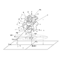
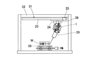
- the parallel link mechanism 1 is installed in a suspended state on an XY stage 34, and a rectangular parallelepiped target work W is installed on a work table 39 that is a Z-axis stage.
- the basic structure of the link actuating device shown in FIG. 2 is the same as that described later with reference to FIG. In such a configuration, there are generally the following methods for causing the end effector 29 to act on the entire circumference of the side surface of the cuboid target workpiece W.
- FIG. 16 shows the positional relationship between the target workpiece and the parallel link mechanism when the configuration shown in FIG. 15 is viewed from above for the purpose of explaining the operation of the configuration shown in FIG.
- the XY stage 33 moves to the position (i)
- the parallel link mechanism 1 moves to a position where the end effector 29 points to the point a on the work side surface.
- the linear motion mechanism 31 here, the Y axis of the XY stage 34
- the parallel link mechanism 1 is fixed, and (ii) to the position.
- the end effector 29 is stopped.
- the XY stage moves to the position (iii)
- the parallel link mechanism 1 moves to a position where the end effector 29 points to point b on the work side surface.
- the end effector 29 is started again, and at the same time, only the linear motion mechanism 31 (here, the X-axis stage 33) is moved to the position (iv) while the parallel link mechanism 1 is fixed, and moved to the position (iv). After completion, the end effector 29 is stopped.
- the end effector 29 can be applied to the entire circumference of the side surface of the cuboid target workpiece W.
- An object of the present invention is to solve the above-mentioned problems in a working device that combines a parallel link mechanism and a linear motion mechanism, and the end effector substantially subtracts the boundary surface from the boundary surface having a steep angle of the surface of the target workpiece. It is an object of the present invention to provide a control device and a control method for a link actuating device that can perform work while moving at a constant speed, and can perform work without causing unevenness on the boundary surface.
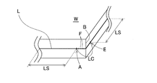
- the control device for the link actuating device includes a parallel link mechanism 1 and a linear motion mechanism 31 that are combined, along a line L that straddles a boundary surface B that is a corner on the work plane S of the target work W.
- the parallel link mechanism 1 is based on a link hub 3 on the distal end side to which the end effector 29 is attached. It has a plurality of actuators 53 to 55 that are connected to the end side link hub 2 via three or more sets of link mechanisms 4 so that the attitude can be changed, and change the attitude of the distal end side link hub 3.
- the linear motion mechanism 31 has a function of linearly moving in the biaxial direction or the triaxial direction orthogonal to each other by driving the actuators 35 to 37, and moving the link hub 2 on the base end side of the parallel link mechanism 1,
- the control device 61 is provided to move the target workpiece W, and the control device 61 stores the line L as line segment data, and the parallel link mechanism 1 and the linear motion mechanism 31 from the stored line L.
- the operation command generation means 65 includes an area dividing unit 67 that divides a line L on the work plane S into a straight line area LS and a corner area LC according to a predetermined rule with respect to the boundary surface B, and the straight line In the area LS, the linear area motion command generating unit 68 that generates a command to operate only the linear motion mechanism 31 while fixing the posture of the parallel link mechanism 1, and in the corner area LC, the linear motion mechanism 31 and the parallel link
- the mechanism 1 includes a corner region operation command generation unit 69 that generates a command so that the action point P of the end effector 29 passes through the boundary surface B at a substantially constant speed by performing the cooperative operation.
- the area dividing unit 67 is along the line L that crosses the boundary surface B that is a corner of the work W on the work plane S, that is, the boundary surface B having a steep angle.
- the line L is divided into a straight line region LS and a corner region LC.
- the parallel link mechanism 1 operates only the linear motion mechanism 31 while being fixed in a desired posture.
- the linear motion mechanism 31 and the parallel link mechanism 1 are controlled so as to perform a cooperative operation, thereby causing the action point P of the end effector 29 to pass through the boundary surface B at a substantially constant speed.
- the action point P of the end effector 29 can operate at substantially constant speed.
- unevenness in work by the end effector 29 can be eliminated.
- the end effector 29 is attached with a laser, a dispenser, an ink jet, or a weld, etc., on the link, the laser processing unevenness, the dispenser, the application unevenness due to the ink jet, and the welding unevenness due to welding can be eliminated.
- the parallel link mechanism 1 operates only the linear motion mechanism 31 and can be operated at high speed, and the posture of the end effector 29 does not change, which is preferable from the viewpoint of work quality.
- a route from the start point A to the end point E of the corner area LC is first divided into a plurality of sections at the passing point F.
- the position of the linear motion mechanism 31 and the posture of the parallel link mechanism 1 in each section are set so that the angle at which the end effector 29 acts changes smoothly.
- the change in the angle at which the end effector 29 acts is assumed to be small enough not to affect the quality after the end effector 29 acts.
- the movement amount (X, Y, Z) of the linear motion mechanism 31 (XYZ stage) and the movement amounts ( ⁇ 1, ⁇ 2, ⁇ 3) of the actuators 53 to 55 constituting the parallel link mechanism 1 in each divided section are calculated. .
- the actuators 35 to 37 and 53 to 55 in the section are calculated.
- the actuators 35 to 37 and 53 to 55 are continuously positioned without acceleration / deceleration, whereby the end effector 29 moves from the start point A to the end point E of the corner region LC at substantially constant speed.
- substantially constant speed means “substantially constant speed” and means that the speed does not change to such an extent that it can be regarded as constant speed from the viewpoint of work by the end effector 29.
- the corner region operation command generation unit 69 divides the route from the start point A to the end point E of the corner region LC into a specified number of sections at a passing point F.
- the movement amounts X, Y, Z of the linear motion mechanism 31 in each divided section and the movement amounts ⁇ 1, ⁇ 2, ⁇ 3 of the actuators 53 to 55 constituting the parallel link mechanism 1 are calculated and designated.
- the area dividing unit 67 includes a movement speed of the linear motion mechanism 31 obtained from the target movement speed designated by the corner area motion command generation unit 69 and the divided passing points F, and a speed limit of the linear motion mechanism 31. From this, the size of the corner area LC may be calculated. Thereby, it is possible to obtain an appropriate size of the corner area LC that can perform a desired cooperative operation.
- the area dividing unit 67 has a table TB indicating the relationship between the size of the corner area LC and the designated target moving speed, and the size of the corner area LC is determined from the target moving speed using the table TB. May be calculated. This also makes it possible to obtain an appropriate size of the corner area LC that can perform a desired cooperative operation.
- the operation command generation means 65 generates an operation command from the line segment data of the line L at the time of operation of the link actuator 41, for example, immediately before or in parallel with the operation for each section. In addition to this, all the settings (for example, operation commands) of each section of the corner area LC are calculated and recorded in the operation command storage means 70 before the link actuator 41 actually operates,
- the control unit 66 may read and control the setting corresponding to the section from the operation command storage unit 70 when operating the link actuating device 41.
- the operation command generation means 65 and the control means 66 may be configured by physically separate computers or the like, and the generated operation command is online or offline on the control means 66 side. May be stored in the operation command storage means 70.
- the work plane S on which the end effector 29 works may be a rectangular parallelepiped outer peripheral surface or an inner peripheral surface.
- the outer peripheral surface and the inner peripheral surface of such a rectangular parallelepiped are the work plane S, the effect that the work can be performed without unevenness of the present invention is more effectively exhibited.
- the link actuator control method is a method for controlling the link actuator 41 having the above-described configuration, wherein the line L on the work plane S is determined in accordance with a predetermined rule based on the boundary surface B.
- the linear area LS is divided into the corner area LC, and in the straight area LS, only the linear motion mechanism 31 is operated while the posture of the parallel link mechanism 1 is fixed, and in the corner area LC, the linear motion mechanism is operated. 31 and the parallel link mechanism 1 perform a cooperative operation so that the action point P of the end effector 29 passes through the boundary surface B at a substantially constant speed.
- the control method stores the line L as line segment data, and issues an operation command to operate the parallel link mechanism 1 and the linear motion mechanism 31 from the stored line L.
- the actuators 35 to 37 of the parallel link mechanism 1 and the linear motion mechanism 31 may be controlled in accordance with the generated operation command.
- the end effector 29 moves along the boundary surface B at a substantially constant speed with respect to the boundary surface B having a steep angle of the surface of the target workpiece, as described for the control device of the present invention.
- the work can be performed without causing unevenness on the boundary surface B.
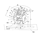
- the control device 61 of this link actuating device is a device that controls a link actuating device 41 in which the parallel link mechanism 1 and the linear motion mechanism 31 are combined, and is a boundary that becomes a corner on the work plane of the target work W. This is applied to the case where the end effector 29 is continuously acted along the line L that straddles the surface B.
- the linear motion mechanism 31 is a mechanism having a function of linearly moving the target workpiece W in three orthogonal directions.
- the linear motion mechanism 31 includes a link side linear motion mechanism portion 31A that moves the target workpiece W in the two axial directions of the X axis and the Y axis, and a workpiece side linear motion that moves the target workpiece W in the Z axis direction. It is comprised with the mechanism part 31B.
- the X, Y, and Z axes are a left-right direction, a front-rear direction, and a vertical direction, respectively, and are orthogonal to each other.
- the link side linear motion mechanism 31A has an X stage 33 installed on the top of the gantry 32 so as to be movable in the X axis direction, and an XY stage 34 installed on the X stage 33 so as to be movable in the Y axis direction. .
- the XY stage 34 is connected to the link hub 2 on the base end side where the parallel link mechanism 1 is located at the upper end thereof, and is installed so that the parallel link mechanism 1 faces downward.
- the X stage 33 and the XY stage 34 are driven forward and backward relative to the gantry 32 and the X stage 33 by X-axis and Y-axis actuators 35 and 36 such as motors, respectively.
- the work-side linear motion mechanism 31B is located below the region where the parallel link mechanism 1 operates, and has a work table 39 that is driven up and down by a Z-axis actuator 37 such as a motor via an elevating mechanism 38. is doing.
- the target work W is placed on the work table 39.
- the end effector 29 is a device that performs a non-contact operation on the target workpiece W, and is, for example, a laser for laser processing, a dispenser for coating, an ink jet nozzle, or a welding torch.
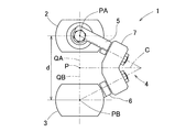
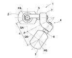
- FIGS. 9A and 9B are front views showing different states of the parallel link mechanism 1.
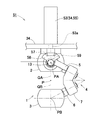
- the parallel link mechanism 1 is configured such that a distal end side link hub 3 is connected to a proximal end side link hub 2 via three sets of link mechanisms 4 so that the posture can be changed. 9A and 9B, only one set of link mechanisms 4 is shown.
- FIG. 7 is a perspective view showing the parallel link mechanism 1 three-dimensionally.
- Each of the three sets of link mechanisms 4 includes a base end side end link member 5, a tip end side end link member 6, and a central link member 7, and includes a three-joint link mechanism consisting of four rotating pairs. Eggplant.
- the end link members 5 and 6 on the base end side and the front end side are L-shaped, and the base ends are rotatably connected to the link hub 2 on the base end side and the link hub 3 on the front end side, respectively.
- the center link member 7 is rotatably connected at one end to the distal end of the proximal end side end link member 5 and at the other end to the distal end side end link member 6.
- the end link members 5 and 6 on the proximal end side and the distal end side have a spherical link structure, and the spherical link centers PA and PB (FIG. 9A) in the three sets of link mechanisms 4 coincide.
- the distance d between the spherical link centers PA and PB is also the same.
- the central axis of each rotational pair of the end link members 5 and 6 and the central link member 7 may have a certain crossing angle ⁇ or may be parallel.
- the three link mechanisms 4 have the same geometric shape.
- the geometrically identical shape is a geometric model in which the link members 5, 6, and 7 are expressed by straight lines, that is, a model that is expressed by each rotation pair and a straight line connecting these rotation pairs.
- the base end side part and the front end side part with respect to the center part of the are said to have a symmetrical shape.
- FIG. 10 is a diagram in which a set of link mechanisms 4 is expressed by a straight line.
- the link mechanism 4 of this embodiment is a rotationally symmetric type, and the positions of the proximal-side link hub 2 and the proximal-side end link member 5, the distal-side link hub 3 and the distal-side end link member 6.
- the relationship is a position configuration that is rotationally symmetric with respect to the center line C of the central link member 7.
- 9A shows a state in which the central axis QA of the link hub 2 on the proximal end side and the central axis QB of the link hub 3 on the distal end side are on the same line
- FIG. 9B shows the central axis of the link hub 2 on the proximal end side.
- the link hub 2 on the proximal end side, the link hub 3 on the distal end side, and the three link mechanisms 4 allow the distal link hub 3 to move in the two orthogonal directions relative to the link hub 2 on the proximal end side.
- a degree mechanism is configured. In other words, it is a mechanism that can freely change the posture of the link hub 3 on the distal end side with respect to the link hub 2 on the proximal end side with two degrees of freedom of rotation.
- This two-degree-of-freedom mechanism is based on the intersection P between the center axis QA of the link hub 2 on the proximal end side, the center axis QB of the link hub 3 on the distal end side, and the center line C of the center link member 7.
- the link hub 3 on the distal end side changes the posture with respect to the link hub 2.
- This two-degree-of-freedom mechanism is compact but can widen the movable range of the link hub 3 on the distal end side relative to the link hub 2 on the proximal end side.
- the maximum value (maximum folding angle) of the bending angle ⁇ (FIG. 7) between the central axis QA of the proximal-side link hub 2 and the central axis QB of the distal-side link hub 3 can be about ⁇ 90 °.
- the turning angle ⁇ of the distal end side link hub 3 relative to the proximal end side link hub 2 can be set in a range of 0 ° to 360 °.
- the bending angle ⁇ is a vertical angle in which the central axis QB of the distal end side link hub 3 is inclined with respect to the central axis QA of the proximal end side link hub 2, and the turning angle ⁇ is the proximal end side link hub.
- This is a horizontal angle at which the central axis QB of the link hub 3 on the distal end side is inclined with respect to the central axis QA of the second axis.
- the proximal end side link hub 2 and the proximal end side end link member 5 and the distal end side link hub 3 and the distal end side end link member 6 move in the same manner.
- the rotation hubs are provided coaxially with the center axes QA and QB on the link hubs 2 and 3 on the proximal end side and the distal end side, and rotation is transmitted from the proximal end side to the distal end side, the proximal end side and the distal end side are It becomes a constant velocity universal joint that rotates at the same speed at the same rotation angle.
- the plane of symmetry of the central link member 7 when rotating at a constant speed is referred to as a uniform speed bisector.
- the plurality of link mechanisms 4 can move without contradiction.
- the central link member 7 is limited to movement only on the equal speed bisector. Thereby, even if the proximal end side and the distal end side have arbitrary operating angles, the proximal end side and the distal end side rotate at a constant speed.
- the base end side link hub 2 and the front end side link hub 3 have a donut shape in which a through hole 10 (FIG. 11) is formed in the center portion along the axial direction and the outer shape is spherical.
- the center of the through hole 10 coincides with the central axes QA and QB of the link hubs 2 and 3.
- the proximal end link member 5 and the distal end link member 6 rotate at equal intervals in the circumferential direction of the outer peripheral surface of the proximal link hub 2 and distal link hub 3 respectively. It is connected freely.
- FIG. 11 is a cross-sectional view showing a rotation pair of the base end side link hub 2 and the base end side end link member 5 and a base end side end link member 5 and the central link member 7.
- radial communication holes 11 that communicate the axial through hole 10 and the outer peripheral side are formed at three locations in the circumferential direction, and two bearings provided in each communication hole 11.
- shaft members 13 are rotatably supported. The outer end of the shaft member 13 protrudes from the link hub 2 on the base end side, and the end link member 5 on the base end side is coupled to the protruding screw portion 13 a and is fastened and fixed by a nut 14.
- the bearing 12 is a rolling bearing such as a deep groove ball bearing, for example, and an outer ring (not shown) is fitted to the inner circumference of the communication hole 11, and an inner ring (not shown) is the outer circumference of the shaft member 13. Is fitted.
- the outer ring is retained by a retaining ring 15.
- a spacer 16 is interposed between the inner ring and the end link member 5 on the base end side, and the tightening force of the nut 14 is transmitted to the inner ring via the end link member 5 and the spacer 16 on the base end side.
- a predetermined preload is applied to the bearing 12.
- the rotating pair of the end link member 5 and the center link member 7 on the base end side is provided with two bearings 19 in communication holes 18 formed at both ends of the center link member 7.
- a shaft portion 20 at the tip of the end link member 5 is rotatably supported.
- the bearing 19 is fastened and fixed by a nut 22 via a spacer 21.
- the bearing 19 is a rolling bearing such as a deep groove ball bearing, for example, and an outer ring (not shown) is fitted to the inner circumference of the communication hole 18, and an inner ring (not shown) is arranged on the outer circumference of the shaft portion 20. It is mated. The outer ring is retained by a retaining ring 23. A tightening force of the nut 22 screwed to the tip screw portion 20a of the shaft portion 20 is transmitted to the inner ring through the spacer 21 to apply a predetermined preload to the bearing 19.
- the rotation pair of the base end side link hub 2 and the base end side end link member 5 and the base end side end link member 5 and the central link member 7 have been described above.
- the rotation pair of the hub 3 and the end link member 6 on the front end side and the rotation pair of the end link member 6 and the center link member 7 on the front end side have the same configuration (not shown).
- each link mechanism 4 that is, the rotation pair of the link hub 2 on the proximal end side and the end link member 5 on the proximal end side, the link hub 3 on the distal end side and the end link on the distal end side Bearings 12 and 19 are provided on the rotational pair of the member 6, the end link member 5 and the central link member 7 on the base end side, and the rotational pair of the end link member 6 and the central link member 7 on the distal end side.
- the parallel link mechanism 1 is in a state in which the base end side link hub 2 is fixed to the lower surface of the XY stage 34 and the front end side link hub 3 is suspended.
- an actuator 53 comprising a motor or other rotary actuator is installed on the upper surface of the XY stage 34.
- the figure shows one link mechanism 4, the other two link mechanisms 4 are also provided with actuators 54 and 55 as described above, and are connected to the link mechanism 4 in the same manner as described below.
- An output shaft 53a of the actuator 53 protrudes downward through the XY stage 34, and a bevel gear 51 attached to the output shaft 53a and a fan-shaped bevel gear 58 attached to the shaft member 13 of the link hub 2 on the proximal end side. I'm engaged.
- the control device 61 includes a command generating unit 62 that generates an operation command from line segment data of the line L of the work plane S of the target work W, and a link actuator according to the generated operation command.
- the control part 63 which controls 41 is provided.
- the command generation unit 62 and the control unit 63 are provided in one computer or the like and conceptually distinguished from each other, or are provided in different devices such as different computers and connected online. However, it may be offline so that data can be exchanged on a recording medium or the like. When it is set as another apparatus, it may be installed in a remote place away from each other.
- the control unit 63 includes a control unit 66 and an operation command storage unit 70.
- the control means 66 is means for controlling the actuators 53, 54, 55 of the parallel link mechanism 1 and the actuators 35, 36, 37 of the linear motion mechanism 31 in accordance with the generated operation command, and is a so-called numerical control device.
- the control means 66 performs position control and speed control of, for example, the actuators 53, 54, 55 of the parallel link mechanism 1 and the actuators 35, 36, 37 of the linear motion mechanism 31, for example, point-to-point.
- the operation command storage means 70 is a means for storing an operation command to be executed by the control means 66 and for storing an operation command generated by the command generation unit 62. Note that when the command generation unit 62 and the control unit 63 are configured to be separated from each other, the command generation unit 62 and the control unit 63 may be provided in both, and the operation command may be transferred between the two.
- the command generation unit 62 includes a line storage unit 64 and an operation command generation unit 65.
- the line storage means 64 stores the line L as numerical line segment data.
- the line segment data stored in the line storage unit 64 is, for example, data of a plurality of line segments that are sequentially connected, and is configured by three-dimensional coordinates indicating the start point and the end point for each line segment.
- the line segment data stored in the line storage unit 64 may further include data for identifying line shapes such as whether the line segment is a straight line or a curve.
- the operation command generation unit 65 is a unit that generates an operation command for operating the parallel link mechanism 1 and the linear motion mechanism 31 from the line segment data of the line L stored in the line storage unit 64.
- the motion command generating means 65 has a region dividing unit 67, a straight region motion command generating unit 68, and a corner region motion generating unit 69.
- the area dividing unit 67 is a means for dividing the line L on the work plane S into a straight line area LS and a corner area LC according to a predetermined rule with reference to the boundary surface B.
- the linear area operation command generation unit 68 is a means for generating an instruction to operate only the linear motion mechanism 31 while fixing the posture of the parallel link mechanism 1 in the linear area LS.
- the corner region motion command generation unit 69 causes the point of action P of the end effector 29 to be substantially constant at the boundary by causing the linear motion mechanism 31 and the parallel link mechanism 1 to cooperate in the corner region LC.
- the area dividing unit 67 as the rule, for example, the target moving speed specified by the corner area operation command generating unit 69, the moving speed of the linear motion mechanism 31 obtained from each divided passing point F, and the linear motion
- the size of the corner area LC may be calculated from the speed limit of the mechanism 31. Thereby, it is possible to obtain an appropriate size of the corner area LC that can perform a desired cooperative operation.
- the area dividing unit 67 has a table TB indicating the relationship between the size of the corner area LC and the designated target moving speed, and the table TB is used to determine the size of the corner area LC from the target moving speed. May be calculated.
- the corner area operation command generation unit 69 divides the path from the start point A to the end point E of the corner area LC into a specified number of sections at the passing point F, for example.
- the corner area operation command generation unit 69 includes the movement amounts X, Y, Z of the linear motion mechanism 31 in each divided section, and the movement amounts ⁇ 1, ⁇ 2, ⁇ 3 of the actuators 53 to 55 constituting the parallel link mechanism 1. Is calculated.
- the corner area operation command generation unit 69 moves the movement time in each section determined from the designated target moving speed and the distance of each section, and the movement amount ⁇ 1 of each of the actuators 53 to 55 and 35 to 37 in each section.
- the corner area operation command generation unit 69 generates a command to continuously position the actuators 35 to 37 and 53 to 55 without acceleration / deceleration in each divided section.
- FIG. 2 A schematic view of the configuration of FIG. 2 viewed from above is shown in FIG.
- the outer peripheral line L of the rectangular parallelepiped side surface on which the end effector 29 acts is divided into a straight line region LS and a corner region LC (LC1 to LC4). Divide into multiple sections with F.
- the circle plots surrounding the numbers represent the coordinates (work coordinate: WX, WY, WZ) on which the end effector 29 acts in the orthogonal coordinate system of the target work W, and the square plots surrounding the numbers are in the orthogonal coordinate system of the XY stage 34.
- the coordinates (stage coordinates: SX, SY) to which the XY stage 34 moves are shown.
- the origin of the work coordinates and the stage coordinates are the same position.
- the arrow from the square plot to the round plot represents the direction in which the end effector 29 acts on the target workpiece W.
- the numbers in the circle plot and the square plot represent the order in which each actuator positions in a series of operations.
- the trajectory of the XY stage 34 is a trajectory having an arc so that the XY stage 34 moves smoothly.
- the motion command generating means 65 is provided with the movement amounts (X, Y, Z) of the respective axes of the linear motion mechanism 31 when moving through the sections divided in the corner area LC, and the actuators 53, 54, 55 movement amounts ⁇ 1, ⁇ 2, ⁇ 3 are calculated for each section.
- the relationship between the movement amount on the three-dimensional orthogonal coordinates (XYZ plane coordinates) and the movement amounts ⁇ 1, ⁇ 2, and ⁇ 3 of the actuators 53 to 55 of the parallel link mechanism 1 will be described later.
- the motion command generation means 65 moves the movement amounts ⁇ 1, ⁇ 2, ⁇ 3 and the respective axes of the linear motion mechanism 31 for each section so that the end effector 29 passes on the side surface of the target workpiece W at a specified speed. Calculate the speed. This calculation method will be described later.
- the series of operations is as follows. First, the linear motion mechanism 31 (XY stage 34, work table 39) and the parallel link mechanism 1 move so that the end effector 29 points to the start point A of the corner region LC1. Thereafter, the end effector 29 is activated, and at the same time, the actuators 53 to 55 and 35 to 37 move to the end point E of the corner area LC1 at the movement amount ( ⁇ 1, ⁇ 2, ⁇ 3, X, Y, Z) and the speed obtained previously. The continuous positioning operation without acceleration / deceleration is performed for each section.
- the area dividing unit 67 calculates the optimum corner area LC by the following method.
- the trajectory of the XY stage 34 in the corner region LC is drawn in a direction perpendicular to the workpiece side surface from the start point A of the corner region LC and in a direction perpendicular to the workpiece side surface from the end point E of the corner region LC.
- a circular arc (square plots 1 to 9) that moves from the start point A to the end point E of the corner area LC with the intersection of the two lines as the center.
- the distance between the parallel link mechanism 1 and the target point P is set to an optimum distance at which the end effector 29 can act on the target point.
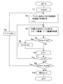
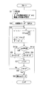
- the corner area operation command generation unit 69 calculates the optimum corner length L according to the procedure of the flowchart shown in FIG.
- the corner region motion command generation unit 69 sets Lint as the minimum minimum corner length as a reference (step T1), and passes through the path from the start point A to the end point E of the corner region LC at Lint.
- Lint as the minimum minimum corner length as a reference
- F Divide into a plurality of sections by F (step 2).
- the number of divisions is D
- D is a value that has as a calculation parameter in advance.
- step T1 the orthogonal coordinates of the nth point (n: natural number) of the target workpiece W at each divided point are (WXn, WYn), and the workpiece orthogonal coordinates of the (n + 1) th point are (WXn + 1, WYn + 1). To do. Similarly, the nth point orthogonal coordinate of the stage at each point is (SXn, SYn), and the n + 1 point stage orthogonal coordinate is (SXn + 1, SYn + 1).
- the corner area operation command generation unit 69 calculates the movement amount (SX, SY, WX, WY, WZ) of the stage coordinates and the work coordinates in each section, and calculates each point from these values and the designated target movement speed.
- the moving speeds of the X stage 33 and the Y stage (in the Y axis direction of the XY stage 34) are calculated. Further, the corner area operation command generation unit 69 sets Vmax to 0 in step T1, and sets n to 1 in step T2.
- step T3 the corner area operation command generation unit 69 acquires the stage coordinates and the work coordinates at each divided point. Then, the corner area operation command generation unit 69 calculates the moving speed Vx of the X stage 33 from the following equation (7). The corner area operation command generation unit 69 calculates Vx in all the divided sections, and sets the maximum Vx as Vxmax (steps T4 to T7).
- the corner area operation command generation unit 69 compares the movement speed Vx of the X stage 33 calculated in step T3 with the maximum value Vxmax of the movement speed Vx of the X stage 33 (step T4). If the moving speed Vx is greater than the maximum value Vxmax (Yes in step T4), the maximum value Vmax is set to Vx (step T5). Then, the corner area operation command generation unit 69 increments n to n + 1 (step T6). When the moving speed Vx is lower than the maximum value Vxmax (No in step T4), the corner area operation command generation unit 69 proceeds to step T6.
- the corner area operation command generation unit 69 compares n with the division number D (step T7). When the division number D is larger than n (Yes in Step T7), the process returns to Step T3. If n is equal to or greater than the division number D (No in step T7), the process proceeds to step T8.
- the route to E is divided into a plurality of sections at a passing point F. Lplus is the amount of addition of the corner length that has as a calculation parameter in advance. Thereafter, the same calculation as described above is performed, and L when Vxmax is equal to or less than Vxlmt (No in step T8) is set as the final corner length Lx (step T10).
- the corner area operation command generation unit 69 performs the same calculation as that for the X stage 33 for the speed in the Y-axis direction of the XY stage 34 to calculate the final corner length Ly. Then, the corner area operation command generation unit 69 compares Lx and Ly and sets the larger one as the final corner length L.
- the action point P of the end effector 29 operates at substantially constant speed. Therefore, unevenness of work by the end effector 29 can be eliminated.
- the end effector 29 for example, when a laser, dispenser, ink jet, welding or the like is attached to the link and the work is performed, it is possible to eliminate laser processing unevenness, dispenser, coating unevenness due to ink jet, and welding unevenness due to welding.
- the area dividing unit 67 divides the straight area LS and the corner area LC, and only the corner area LC is cooperatively operated. Therefore, it is possible to efficiently generate a command for the cooperative operation in a short time. Further, in the linear motion region LS, the parallel link mechanism 1 operates only the linear motion mechanism 31 and can be operated at high speed, and the posture of the end effector 29 does not change, which is preferable from the viewpoint of work quality.
- FIG. 6 shows an example in which the work plane S of the target work W causes the end effector 9 to act on the inner peripheral surface of the rectangular parallelepiped side surface.
- This figure is a schematic view of the configuration of FIG. 2 as viewed from above.
- the region dividing unit 67 divides the inner peripheral line L of the rectangular parallelepiped into a straight region LS and corner regions LC (LC1 to LC4), and a corner region operation command generating unit 69
- the path from the start point A to the end point E of the corner area LC is divided into a plurality of sections at the passing point F.
- the coordinate position of each axis of the linear motion mechanism 31 at each divided point is determined as follows, for example.
- the position of the linear motion mechanism 31 at the start point A (circle plot 1) and the end point E (circle plot 9) is located on a line perpendicular to the work side surface in a direction in which the end effector 29 points to the start point A and end point E from the inside. (Square plot 1, square plot 9).
- the position of the linear motion mechanism 31 (XY stage 34) at the corner edge point (circle plot 5) is located on the bisector of the corner angle in a direction in which the end effector 29 points to the corner edge point from the inside (square plot). 5).
- the distance between the parallel link mechanism 1 and the divided target points is an optimum distance at which the end effector 29 can act on the target points.
- the position of the linear motion mechanism 31 (XY stage 34) at each point other than the start point A, the corner edge point (point on the boundary surface B), and the end point E is the straight line at the start point A, the corner edge point, and the end point E. It is set on a straight line connecting the positions of the moving mechanism 31 (XY stage 34) (square plot 1, square plot 5, square plot 9).
- the circle plot represents coordinates (work coordinates: WX, WY, WZ) on which the end effector 29 operates in the orthogonal coordinate system of the workpiece
- the square plot represents coordinates in which the XY stage 34 moves in the orthogonal coordinate system of the linear motion mechanism 31 ( Stage coordinates: SX, SY).
- the boundary surface B having a steep angle of the surface of the target workpiece W is used.
- the end effector 29 can work while moving the boundary surface B at substantially constant speed, and the work can be performed without causing unevenness on the boundary surface B.
- FIG. 12 shows a calculation flowchart and a calculation formula for obtaining the posture (folding angle ⁇ , turning angle ⁇ ) of the link hub 3 on the distal end side from three-dimensional orthogonal coordinates (XYZ plane coordinates).
- the calculation in the figure is performed by a convergence calculation by the method of least squares.
- the height h ′ (see FIG. 13) from the rotation center of the link hub 2 on the base end side to the target coordinate T is the distance d between the link spherical centers and the height from the reference plane to the base link spherical center.
- d and h are fixed values determined by the link size and the device size.
- the distance between O ′ and the target coordinate T is obtained as r ′ from the equation relating to ⁇ as shown in equation (3). Therefore, as shown in Expression (4), the bending angle ⁇ is determined by searching for the bending ⁇ that minimizes the difference between r (calculated from x and y of the target coordinates T) and r ′ (calculated from the bending angle ⁇ ). obtain.
- ⁇ that minimizes dr.
- the range of ⁇ is 0 ° to less than 90 °, and the maximum angle varies depending on the link specifications.
- r is obtained from equation (1) (step S1).
- the current number of repetitions j is reset to zero, and an initial setting value ⁇ ′ for searching for the bending angle ⁇ and a number of repetitions N for searching are set.
- ⁇ ′ is set to a value that is half the maximum bending angle.
- the optimum N is determined from the relationship between the accuracy of the bending angle ⁇ and the allowable processing time.
- ⁇ ′ ⁇ ′ / 2 is set (step S3).
- step S8 if the current number of repetitions j has not reached the set number of repetitions N, the process returns to step S3. This flow is repeated up to the number of repetitions N, and Ans ⁇ obtained at the end is the required bending angle ⁇ . After obtaining the bending angle, the turning angle is obtained as shown in equations (5) and (6).
- the target tip posture is defined by the bending angle ⁇ and the turning angle ⁇ thus obtained.
- the number of computations can be reduced by performing the convergence calculation by the least square method to obtain the bending angle ⁇ by sequentially searching from the vicinity of the current coordinate position as a reference.
- the movement amount (hereinafter referred to as “rotation angle”) ⁇ n (n: 1 to 3) for operating the actuators 53 to 55 of the parallel link mechanism 11 is calculated.
- the rotation angle ⁇ n is shown in FIG. 13 showing the same parallel link mechanism 1 as FIG. 7, and each amount necessary for explanation is shown.
- the rotation angle ⁇ n is obtained, for example, by inversely transforming the following equation (8).
- the inverse transformation is a transformation for calculating the rotation angle ⁇ n from the bending angle ⁇ and the turning angle ⁇ .
- the bending angle ⁇ , the turning angle ⁇ , and the rotation angle ⁇ n are mutually related, and the other value can be derived from one value.
- ⁇ 1, 2, 3
- ⁇ is a connecting end shaft of the central link member 7 rotatably connected to the end link member 5 on the base end side, and a central link member rotatably connected to the end link member 6 on the distal end side. 7 is an angle formed by the connecting end axis 7.
- ⁇ n is a circumferential separation angle of each base end side end link member 5 with respect to the base end side end link member 5 serving as a reference.
- the rotation angle ⁇ n may be obtained by inversely transforming the equation (8) when necessary, but a table (not shown) indicating the relationship between the tip position and orientation and the rotation angle ⁇ n is created in advance. Also good.
- the moving speed will be described.
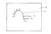
- the plan view shown in FIG. 14 will be used.
- the orthogonal coordinate of the n-th point is (Xn, Yn), and n ⁇
- the orthogonal coordinates of the first point are (Xn-1, Yn-1)
- the movement amounts of the ⁇ 1, ⁇ 2, and ⁇ 3 axes from the (n ⁇ 1) th point to the nth point are ⁇ 1, ⁇ 2, and ⁇ 3,
- the movement speeds V1n, V2n, and V3n of each axis when moving to the Nth point can be expressed by the following equations.
- each point on the work plane S is constant at a specified speed V.
- Vn the combined speed
- the orthogonal coordinates of the target workpiece W the orthogonal coordinates of the n-th point are (Xn, Yn) as in FIG.
- the Cartesian coordinates of the (n-1) th point are (Xn-1, Yn-1)
- the ⁇ 1, ⁇ 2, ⁇ 3, X, and Y axes from the (n-1) th point to the nth point If the movement amounts are ⁇ 1, ⁇ 2, ⁇ 3, ⁇ x, and ⁇ y, the movement speeds V1n ′′, V2n ′′, V3n ′′, Vxn ′′, and Vyn ′′ of each axis when moving to the nth point can be expressed by the following equations.
- the moving speeds of the ⁇ 1 axis, ⁇ 2 axis, and ⁇ 3 axis are moving speeds of rotation angles.
- the end effector 29 substantially defines the boundary surface B with respect to the boundary surface B having a steep angle of the surface of the target workpiece W. Therefore, the work can be performed while moving at a constant speed, and the work can be performed without causing unevenness on the boundary surface B.
Landscapes
- Engineering & Computer Science (AREA)
- Robotics (AREA)
- Mechanical Engineering (AREA)
- Physics & Mathematics (AREA)
- Optics & Photonics (AREA)
- Plasma & Fusion (AREA)
- Geometry (AREA)
- Human Computer Interaction (AREA)
- Manufacturing & Machinery (AREA)
- General Physics & Mathematics (AREA)
- Automation & Control Theory (AREA)
- Health & Medical Sciences (AREA)
- General Health & Medical Sciences (AREA)
- Orthopedic Medicine & Surgery (AREA)
- Manipulator (AREA)
- Numerical Control (AREA)
Abstract
La présente invention permet, au sein d'un dispositif en fonctionnement combinant un mécanisme de liaison parallèle et un mécanisme de mouvement linéaire, de réaliser un travail au niveau d'une surface de délimitation à forte inclinaison d'une surface de pièce cible en même temps qu'un effecteur terminal est déplacé à une vitesse sensiblement constante sur la surface de délimitation, sans que des irrégularités ne se produisent au niveau de la surface de délimitation. Des moyens de génération d'instructions d'utilisation (70) comprennent une unité de division de région (67) qui divise une ligne (L) sur une surface plane usinée (S) d'une pièce cible W en une région de ligne droite (LS) et en une région de coin (LC), sur la base d'une surface de délimitation pentue (B). Les moyens de génération d'instructions d'utilisation comprennent une unité de génération d'instructions d'utilisation pour région de ligne droite (68) qui génère une instruction selon laquelle, dans la région de ligne droite (LS), seul le mécanisme de mouvement linéaire (31) est amené à se déplacer, en même temps que la position du mécanisme de liaison parallèle (1) reste fixe. Les moyens de génération d'instructions d'utilisation comprennent également une unité de génération d'instructions d'utilisation pour région de coin (69) qui génère une instruction selon laquelle, dans la région de coin (LC), le mécanisme de mouvement linéaire (31) et le mécanisme de liaison parallèle (1) fonctionnent de manière coordonnée de sorte qu'un point d'action (P) d'un effecteur terminal (29) traverse la surface de délimitation (B) à une vitesse sensiblement constante.
Priority Applications (3)
| Application Number | Priority Date | Filing Date | Title |
|---|---|---|---|
| EP18757063.5A EP3587041B1 (fr) | 2017-02-24 | 2018-02-20 | Dispositif de commande et procédé de commande de dispositif d'utilisation de liaison |
| CN201880013323.0A CN110325326B (zh) | 2017-02-24 | 2018-02-20 | 连杆促动装置的控制装置和控制方法 |
| US16/545,626 US11130229B2 (en) | 2017-02-24 | 2019-08-20 | Link operating device control device and control method |
Applications Claiming Priority (2)
| Application Number | Priority Date | Filing Date | Title |
|---|---|---|---|
| JP2017033520A JP6800044B2 (ja) | 2017-02-24 | 2017-02-24 | リンク作動装置の制御装置および制御方法 |
| JP2017-033520 | 2017-02-24 |
Related Child Applications (1)
| Application Number | Title | Priority Date | Filing Date |
|---|---|---|---|
| US16/545,626 Continuation US11130229B2 (en) | 2017-02-24 | 2019-08-20 | Link operating device control device and control method |
Publications (1)
| Publication Number | Publication Date |
|---|---|
| WO2018155444A1 true WO2018155444A1 (fr) | 2018-08-30 |
Family
ID=63253159
Family Applications (1)
| Application Number | Title | Priority Date | Filing Date |
|---|---|---|---|
| PCT/JP2018/006044 Ceased WO2018155444A1 (fr) | 2017-02-24 | 2018-02-20 | Dispositif de commande et procédé de commande de dispositif d'utilisation de liaison |
Country Status (5)
| Country | Link |
|---|---|
| US (1) | US11130229B2 (fr) |
| EP (1) | EP3587041B1 (fr) |
| JP (1) | JP6800044B2 (fr) |
| CN (1) | CN110325326B (fr) |
| WO (1) | WO2018155444A1 (fr) |
Families Citing this family (5)
| Publication number | Priority date | Publication date | Assignee | Title |
|---|---|---|---|---|
| JP6719956B2 (ja) * | 2016-04-20 | 2020-07-08 | Ntn株式会社 | 双腕型作動装置 |
| WO2019049972A1 (fr) * | 2017-09-08 | 2019-03-14 | Ntn株式会社 | Dispositif de travail utilisant un mécanisme à liaison parallèle |
| JP7579119B2 (ja) * | 2020-11-20 | 2024-11-07 | Ntn株式会社 | 作業装置 |
| JP7666199B2 (ja) * | 2021-07-30 | 2025-04-22 | セイコーエプソン株式会社 | ロボットシステムの制御方法およびロボットシステム |
| JP2024011613A (ja) * | 2022-07-15 | 2024-01-25 | 日鉄エンジニアリング株式会社 | 制御システム |
Citations (5)
| Publication number | Priority date | Publication date | Assignee | Title |
|---|---|---|---|---|
| JP2002096170A (ja) * | 2000-09-19 | 2002-04-02 | Daihen Corp | アーク溶接ロボットの自動プログラミング法における自動センシングプロセスの修正法 |
| JP2005144627A (ja) | 2003-11-18 | 2005-06-09 | Ntn Corp | リンク作動装置 |
| JP2015155124A (ja) | 2014-02-20 | 2015-08-27 | Ntn株式会社 | リンク作動装置の制御装置および制御方法 |
| JP2015188945A (ja) * | 2014-03-27 | 2015-11-02 | Ntn株式会社 | 塗布装置 |
| JP2016107374A (ja) | 2014-12-05 | 2016-06-20 | Ntn株式会社 | リンク作動装置の操作装置 |
Family Cites Families (13)
| Publication number | Priority date | Publication date | Assignee | Title |
|---|---|---|---|---|
| US5057758A (en) * | 1989-03-20 | 1991-10-15 | Hewlett-Packard Company | Passive payload for a cartridge handling system |
| US6330837B1 (en) * | 1997-08-28 | 2001-12-18 | Microdexterity Systems, Inc. | Parallel mechanism |
| US6840127B2 (en) * | 2003-02-05 | 2005-01-11 | Michael Julius Moran | Tendon link mechanism with six degrees of freedom |
| US7842904B2 (en) * | 2004-10-21 | 2010-11-30 | Panasonic Corporation | Welding system and consumable electrode welding method |
| US8897916B2 (en) * | 2007-03-01 | 2014-11-25 | Tokyo Institute Of Technology | Maneuvering system having inner force sense presenting function |
| US8700213B2 (en) * | 2007-03-01 | 2014-04-15 | Tokyo Institute Of Technology | Maneuvering system having inner force sense presenting function |
| CN101544020B (zh) * | 2009-04-15 | 2011-05-11 | 上海中技桩业股份有限公司 | 一种预应力高强混凝土桩的制备方法 |
| EP3511129B1 (fr) * | 2012-03-23 | 2021-03-10 | NTN Corporation | Procédé de commande du fonctionnement d'un dispositif d'actionnement de liaison et dispositif de commande correspondant |
| JP6250372B2 (ja) * | 2013-11-22 | 2017-12-20 | Ntn株式会社 | 自動溶接機 |
| JP6324033B2 (ja) * | 2013-11-22 | 2018-05-16 | Ntn株式会社 | リンク作動装置 |
| US9827678B1 (en) * | 2016-05-16 | 2017-11-28 | X Development Llc | Kinematic design for robotic arm |
| CN106425195B (zh) * | 2016-08-29 | 2018-01-26 | 芜湖银星汽车零部件有限公司 | 一种工业焊接机器人 |
| US10737817B2 (en) * | 2016-09-26 | 2020-08-11 | Yaskawa America, Inc. | Method, apparatus, and system for robotic article handling |
-
2017
- 2017-02-24 JP JP2017033520A patent/JP6800044B2/ja active Active
-
2018
- 2018-02-20 CN CN201880013323.0A patent/CN110325326B/zh active Active
- 2018-02-20 WO PCT/JP2018/006044 patent/WO2018155444A1/fr not_active Ceased
- 2018-02-20 EP EP18757063.5A patent/EP3587041B1/fr active Active
-
2019
- 2019-08-20 US US16/545,626 patent/US11130229B2/en active Active
Patent Citations (5)
| Publication number | Priority date | Publication date | Assignee | Title |
|---|---|---|---|---|
| JP2002096170A (ja) * | 2000-09-19 | 2002-04-02 | Daihen Corp | アーク溶接ロボットの自動プログラミング法における自動センシングプロセスの修正法 |
| JP2005144627A (ja) | 2003-11-18 | 2005-06-09 | Ntn Corp | リンク作動装置 |
| JP2015155124A (ja) | 2014-02-20 | 2015-08-27 | Ntn株式会社 | リンク作動装置の制御装置および制御方法 |
| JP2015188945A (ja) * | 2014-03-27 | 2015-11-02 | Ntn株式会社 | 塗布装置 |
| JP2016107374A (ja) | 2014-12-05 | 2016-06-20 | Ntn株式会社 | リンク作動装置の操作装置 |
Non-Patent Citations (1)
| Title |
|---|
| See also references of EP3587041A4 |
Also Published As
| Publication number | Publication date |
|---|---|
| US20190366535A1 (en) | 2019-12-05 |
| CN110325326A (zh) | 2019-10-11 |
| EP3587041A4 (fr) | 2020-12-23 |
| CN110325326B (zh) | 2022-11-01 |
| US11130229B2 (en) | 2021-09-28 |
| JP6800044B2 (ja) | 2020-12-16 |
| EP3587041A1 (fr) | 2020-01-01 |
| EP3587041B1 (fr) | 2024-03-27 |
| JP2018138323A (ja) | 2018-09-06 |
Similar Documents
| Publication | Publication Date | Title |
|---|---|---|
| US11130229B2 (en) | Link operating device control device and control method | |
| US10065310B2 (en) | Device and method for controlling link actuation device | |
| JP6453066B2 (ja) | リンク作動装置の制御方法 | |
| CN101722365B (zh) | 特别用于激光加工机的操作头 | |
| JP6067805B1 (ja) | リンク作動装置を用いた複合作業装置 | |
| CN103063213A (zh) | 一种焊接机器人与变位机位姿关系的标定方法 | |
| JP5818987B2 (ja) | 溝加工方法、工作機械の制御装置および工具経路生成装置 | |
| JP7140508B2 (ja) | パラレルリンク機構を用いた作業装置およびその制御方法 | |
| JP2016002628A (ja) | 加工軌道生成装置と方法 | |
| CN212009367U (zh) | 评价用工件 | |
| KR101787865B1 (ko) | 다관절 링크 기구의 역운동학 해법, 및 이 역운동학 해법을 이용한 교시 데이터 작성 장치 | |
| JP6057284B2 (ja) | 多関節ロボット及び半導体ウェハ搬送装置 | |
| WO2016084685A1 (fr) | Appareil de travail employant un mécanisme de liaison parallèle | |
| JP4498072B2 (ja) | 溶接ロボット用ポジショナの設定方法 | |
| JP4961447B2 (ja) | Nc加工装置 | |
| JP7070114B2 (ja) | ロボット制御装置及びロボット制御方法 | |
| CN113165185B (zh) | 连杆动作装置的控制装置 | |
| JPS62154006A (ja) | ロボツト制御装置 | |
| JP3278798B2 (ja) | 円加工装置 | |
| JP6563658B2 (ja) | パラレルリンク機構を用いた作業装置 | |
| JP6851361B2 (ja) | リンク作動装置の制御方法 | |
| JPH01228693A (ja) | ティーチング機能を備えたレーザ加工機 | |
| JPS63260775A (ja) | 産業用ロボツトの動作方法 | |
| JPS59186006A (ja) | ロボツトの制御方法 |
Legal Events
| Date | Code | Title | Description |
|---|---|---|---|
| 121 | Ep: the epo has been informed by wipo that ep was designated in this application |
Ref document number: 18757063 Country of ref document: EP Kind code of ref document: A1 |
|
| NENP | Non-entry into the national phase |
Ref country code: DE |
|
| ENP | Entry into the national phase |
Ref document number: 2018757063 Country of ref document: EP Effective date: 20190924 |