WO2018163371A1 - Dispositif de traitement d'informations, procédé de traitement d'informations, programme informatique et support d'enregistrement - Google Patents
Dispositif de traitement d'informations, procédé de traitement d'informations, programme informatique et support d'enregistrement Download PDFInfo
- Publication number
- WO2018163371A1 WO2018163371A1 PCT/JP2017/009558 JP2017009558W WO2018163371A1 WO 2018163371 A1 WO2018163371 A1 WO 2018163371A1 JP 2017009558 W JP2017009558 W JP 2017009558W WO 2018163371 A1 WO2018163371 A1 WO 2018163371A1
- Authority
- WO
- WIPO (PCT)
- Prior art keywords
- information
- processing unit
- processing
- verification
- dsp
- Prior art date
- Legal status (The legal status is an assumption and is not a legal conclusion. Google has not performed a legal analysis and makes no representation as to the accuracy of the status listed.)
- Ceased
Links
Images







Classifications
-
- G—PHYSICS
- G06—COMPUTING OR CALCULATING; COUNTING
- G06F—ELECTRIC DIGITAL DATA PROCESSING
- G06F11/00—Error detection; Error correction; Monitoring
- G06F11/07—Responding to the occurrence of a fault, e.g. fault tolerance
- G06F11/0703—Error or fault processing not based on redundancy, i.e. by taking additional measures to deal with the error or fault not making use of redundancy in operation, in hardware, or in data representation
- G06F11/0706—Error or fault processing not based on redundancy, i.e. by taking additional measures to deal with the error or fault not making use of redundancy in operation, in hardware, or in data representation the processing taking place on a specific hardware platform or in a specific software environment
- G06F11/0721—Error or fault processing not based on redundancy, i.e. by taking additional measures to deal with the error or fault not making use of redundancy in operation, in hardware, or in data representation the processing taking place on a specific hardware platform or in a specific software environment within a central processing unit [CPU]
- G06F11/0724—Error or fault processing not based on redundancy, i.e. by taking additional measures to deal with the error or fault not making use of redundancy in operation, in hardware, or in data representation the processing taking place on a specific hardware platform or in a specific software environment within a central processing unit [CPU] in a multiprocessor or a multi-core unit
-
- G—PHYSICS
- G05—CONTROLLING; REGULATING
- G05B—CONTROL OR REGULATING SYSTEMS IN GENERAL; FUNCTIONAL ELEMENTS OF SUCH SYSTEMS; MONITORING OR TESTING ARRANGEMENTS FOR SUCH SYSTEMS OR ELEMENTS
- G05B19/00—Program-control systems
- G05B19/02—Program-control systems electric
- G05B19/04—Program control other than numerical control, i.e. in sequence controllers or logic controllers
- G05B19/042—Program control other than numerical control, i.e. in sequence controllers or logic controllers using digital processors
- G05B19/0428—Safety, monitoring
-
- G—PHYSICS
- G06—COMPUTING OR CALCULATING; COUNTING
- G06F—ELECTRIC DIGITAL DATA PROCESSING
- G06F11/00—Error detection; Error correction; Monitoring
- G06F11/07—Responding to the occurrence of a fault, e.g. fault tolerance
- G06F11/14—Error detection or correction of the data by redundancy in operations
- G06F11/1479—Generic software techniques for error detection or fault masking
- G06F11/1487—Generic software techniques for error detection or fault masking using N-version programming
-
- G—PHYSICS
- G06—COMPUTING OR CALCULATING; COUNTING
- G06F—ELECTRIC DIGITAL DATA PROCESSING
- G06F11/00—Error detection; Error correction; Monitoring
- G06F11/07—Responding to the occurrence of a fault, e.g. fault tolerance
- G06F11/16—Error detection or correction of the data by redundancy in hardware
- G06F11/1629—Error detection by comparing the output of redundant processing systems
- G06F11/1641—Error detection by comparing the output of redundant processing systems where the comparison is not performed by the redundant processing components
-
- G—PHYSICS
- G06—COMPUTING OR CALCULATING; COUNTING
- G06F—ELECTRIC DIGITAL DATA PROCESSING
- G06F11/00—Error detection; Error correction; Monitoring
- G06F11/22—Detection or location of defective computer hardware by testing during standby operation or during idle time, e.g. start-up testing
- G06F11/2289—Detection or location of defective computer hardware by testing during standby operation or during idle time, e.g. start-up testing by configuration test
Definitions
- the present invention relates to an information processing apparatus and method, a computer program, and a recording medium, and more particularly, to a technical field of an information processing apparatus and method having a failure detection function, a computer program, and a recording medium.
- a device for example, a device has been proposed in which an LED (Light Emitting Diode) and a light receiving element are arranged around a medical tube, and hematocrit of blood flowing in the medical tube is measured from the received light signal ( Patent Document 1).
- a device is proposed that irradiates a tube in which blood flows inside with a laser beam and corrects the blood flow calculated from the Doppler shift of the laser beam based on the blood concentration calculated from the amount of light received by the light receiving element. (See Patent Document 2).
- the first and second subsystems to which the same physical quantity is input, and a calculation model for generating a pseudo output by estimating the output of the first or second subsystem by modeling, are provided. And an apparatus that compares the output and pseudo output of the second subsystem to determine which one of the first and second subsystems is faulty (see Patent Document 3).
- the present invention has been made in view of the above problems, for example, and provides an information processing apparatus and method, a computer program, and a recording medium capable of detecting a failure while suppressing an increase in manufacturing cost and apparatus size. Let it be an issue.
- a first information processing apparatus performs a first process on sensor information acquired from a sensor to generate first information;
- a second processing unit that performs second processing different from the first processing to generate second information, and third processing that is processing corresponding to at least part of the second processing for the first information.
- a third processing unit for generating the third information, obtaining the second information, and outputting the second information and the third information.
- a second information processing apparatus of the present invention includes a first processing unit that acquires sensor information from a sensor, a second processing unit, a third processing unit, the first processing unit, A first signal path through the second processing unit and the third processing unit; and a second signal path through the first processing unit and the third processing unit without the second processing unit.
- the third processing unit acquires (i) the signal processed by the second processing unit through the first signal path, and (ii) converts the signal processed by the first processing unit to the second signal. It is acquired by a route, and at least a part of the processing in the second processing unit is simulated.
- An information processing method of the present invention is an information processing method in an information processing apparatus including a first processing unit, a second processing unit, and a third processing unit in order to solve the above-described problem, wherein the first processing unit includes: A step of generating a first information by performing a first process on the sensor information acquired from the sensor, and a second process different from the first process is performed on the first information by the second processing unit. A step of generating two information, and a step of generating third information by the third processing unit performing a third process that is a process corresponding to at least a part of the second process on the first information, The third processing unit includes the step of acquiring the second information and outputting the second information and the third information.
- a computer program includes a first processing unit configured to perform a first process on sensor information acquired from a sensor and generate a first information by using a computer installed in an information processing apparatus.
- a second processing unit that generates a second information by performing a second process different from the first process on the first information, and corresponds to at least a part of the second process with respect to the first information.
- a third process which is a process, is performed to generate third information, and the second information is acquired and functions as a third processing unit that outputs the second information and the third information.
- the information processing apparatus includes a first processing unit that performs first processing on sensor information acquired from a sensor to generate first information, and first information that is different from the first processing.
- a second processing unit that performs the second process to generate the second information, a third process that is a process corresponding to at least a part of the second process is performed on the first information to generate the third information, and the second information
- a third processing unit that acquires information and outputs second information and third information.
- a first processing unit including a memory, a processor, and the like performs first processing on sensor information to generate first information.
- a second processing unit including a memory, a processor, and the like performs second processing on the first information to generate second information.
- a third processing unit including a memory, a processor, etc. acquires the second information from the second processing unit, and outputs the acquired second information.
- the first information is input to the third processing unit in addition to the second processing unit.
- the third process unit also applies the second process as the third process to the first information.
- second information as third information is generated. Therefore, if the second information generated by the second processing unit is compared with the second information as the third information generated by the third processing unit, whether or not the information processing apparatus functions normally. (In other words, whether or not a failure has occurred) can be detected.
- the third process corresponds to a part of the second process
- the information generated when the part of the second process is applied to the first information in the second processing unit, What is necessary is just to comprise the said information processing apparatus so that it may input into a 3rd process part in addition to 2nd information.
- the first information is input to the third processing unit that acquires and outputs the second information from the second processing unit, and the second processing is performed on the input first information.
- a third process corresponding to at least a part is performed. That is, in the information processing apparatus, the third processing unit is caused to simulate at least a part of the second processing in the second processing unit.
- two sets of the same hardware configuration are not provided, but the same process as the second process or a part of the second process is performed in software.
- the first processing unit gives additional information to the first information to be subjected to the third processing in the third processing unit, among the first information.
- the load on the third processing unit can be reduced as compared with the case where the third processing is performed on all the first information output from the first processing unit. This is very advantageous in practice.
- the third processing unit may acquire only the first information to which the additional information is given from the first processing unit. If comprised in this way, the communication load between a 3rd process part and a 1st process part can be reduced.
- the third processing unit performs the second process as the third process on the first information.
- the failure detection can be performed by comparing the second information generated by the second processing unit with the third information as a result of the third processing.
- the second processing unit performs the second process on the first information to which the additional information is added to generate the second information, and the additional information is added.
- the first information is subjected to one part of the second processing to generate fourth information
- the third processing unit performs the second processing as the third processing on the first information to which the additional information is added.
- the first information may be processed to generate the third information
- the fourth information may be acquired in addition to the second information
- the second information, the fourth information, and the third information may be output.
- the second processing unit performs the first part of the second process on each of the plurality of first information that is temporally continuous, and the plurality of continuous information A plurality of continuous first partial information corresponding to each of the first information is generated, and processing of the first part is performed on some continuous first partial information among the plurality of continuous first partial information
- the second part information is generated by performing the second part of the second process different from the first part
- the third processing unit performs the second process as part of the third process for the first information to which the additional information is added.
- the first part of the two processes is performed, third part information is generated as a part of the third information, a plurality of pieces of the first part information are acquired, and additional information is given among the plurality of pieces of the first part information.
- the first partial information corresponding to the first information and the third partial information are output, and the third partial information and a part of the continuous information are output.
- the second part of the second process as the other part of the third process with respect to the plurality of first part information excluding the first part information corresponding to the first information to which the additional information is given among the first part information of the number
- the partial processing may be performed to generate fourth partial information as another part of the third information, acquire the second partial information, and output the second partial information and the fourth partial information.
- N1 first portions that are continuous in time for example, N1 pieces (N1 is a natural number) of the first information are applied to each of the first information.
- N1 pieces of first partial information N2 is a natural number smaller than N1
- the third processing unit performs the first part of the second process as a part of the third process on the first information to which the additional information is given, and generates the third part information. If the third partial information is compared with the first partial information corresponding to the first information to which the additional information used for generating the third partial information is given among the N1 first partial information, Failure detection for the process (i) can be performed.
- the third processing unit further corresponds to the first information to which the additional information used for generating the third partial information is added among the third partial information and the extracted N2 first partial information.
- the fourth part information is generated by performing the second part of the second process as the other part of the third process on the (N2-1) pieces of first part information excluding the first part information. To do.
- the fourth partial information By comparing the fourth partial information with the second partial information, it is possible to detect a failure in the process (ii).
- a part of the result of the first part of the second process in the second processing unit is diverted, so that the load on the third processing unit can be reduced. it can.
- the second processing unit applies the first part of the second process to each of a plurality of pieces of first information that are temporally continuous.
- the processing is performed to generate a plurality of continuous first partial information corresponding to the continuous first information, and (I-ii) a part of the continuous first partial information is continued.
- the second part information is generated by performing the second part process of the second process different from the process of the first part on the plurality of first part information, and (II) the third processing unit (II ⁇ i) Acquiring part of a plurality of pieces of first partial information, applying the second part of the second process as part of the third process to the plurality of first part information obtained, Fifth partial information is generated as part of the third information, (II-ii) second partial information is acquired, and the second partial information and the fifth partial information Output, the second processing unit, when there is a request from the third processing unit, a plurality of first partial information to part of a continuous, outputs the third processing unit.
- the fifth partial information and the second partial information can be compared. For example, failure detection can be performed for the processing of the second part of the second processing unit.
- the second processing unit outputs a plurality of pieces of first partial information to the third processing unit when requested by the third processing unit, so that the third processing unit is output from the second processing unit.
- the memory capacity for holding the first partial information and the like can be reduced.
- the third processing unit acquires the first information via the second processing unit. According to this aspect, in order for the third processing unit to acquire the first information, for example, there is no need to separately provide a route or the like for connecting the first processing unit and the third processing unit, which is very advantageous in practice. is there.
- the second processing unit performs the second process on the first information to be subjected to the third process in the third processing unit among the first information. Additional information is added to the second information generated by the above. According to this aspect, the second information to be compared with the third information generated by performing the third process on the first information can be identified relatively easily.
- the second processing unit divides the first information to be output to the third processing unit into a plurality of sixth part information, and the plurality of sixth part information Is output to the third processing unit. According to this aspect, when the first information is transmitted to the third processing unit via the second processing unit, the transmission of the second information from the second processing unit to the third processing unit is delayed. Can be suppressed.
- An information processing apparatus includes a first processing unit that acquires sensor information from a sensor, a second processing unit, a third processing unit, a first processing unit, a second processing unit, and a third processing unit. And a second signal path through the first processing unit and the third processing unit without going through the second processing unit.
- the third processing unit acquires (i) the signal processed by the second processing unit through the first signal path, and (ii) acquires the signal processed by the first processing unit through the second signal path, 2 Simulate at least a part of the processing in the processing unit.
- the processing in the second processing unit is performed in software as in the information processing apparatus according to the first embodiment described above. Therefore, according to the information processing apparatus according to the second embodiment, similarly to the information processing apparatus according to the first embodiment described above, failure detection can be performed while suppressing an increase in manufacturing cost and device size.
- the information processing method is an information processing method in an information processing apparatus including a first processing unit, a second processing unit, and a third processing unit.
- the first processing unit performs a first process on the sensor information acquired from the sensor to generate the first information
- the second processing unit performs the first process on the first information.
- failure detection can be performed while suppressing an increase in manufacturing cost and device size, similarly to the information processing device according to the first embodiment described above.
- various aspects similar to the various aspects of the information processing apparatus according to the first embodiment described above can be employed.
- the computer program includes a first processing unit that generates a first information by performing a first process on sensor information acquired from a sensor, and a computer installed in the information processing apparatus.
- a second processing unit that performs second processing different from the first processing to generate second information, and third information that is processing corresponding to at least a part of the second processing is applied to the first information.
- the third processing unit that acquires the second information and outputs the second information and the third information.
- the information processing apparatus according to the first embodiment described above can be realized relatively easily by causing the computer installed in the information processing apparatus to execute the computer program.
- failure detection can be performed while suppressing an increase in manufacturing cost and device size, as in the information processing apparatus according to the first embodiment described above.
- the recording medium according to the embodiment records the computer program according to the above-described embodiment.
- a CD-ROM Compact Disc Read Only Memory
- DVD-ROM DVD Read Only Memory
- the recording medium according to the embodiment a CD-ROM (Compact Disc Read Only Memory), a DVD-ROM (DVD Read Only Memory) or the like in which a computer program is recorded is read into a computer mounted on the information processing apparatus. If the recorded computer program is executed, the information processing apparatus according to the first embodiment described above can be realized relatively easily. As a result, according to the recording medium according to the embodiment, failure detection can be performed while suppressing an increase in manufacturing cost and apparatus size, as in the information processing apparatus according to the first embodiment described above.
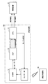
- FIG. 1 is a block diagram illustrating the configuration of the measurement system according to the first embodiment.
- the measurement system includes a measurement device 10 as an example of an information processing device according to the present invention, and a control device 20.
- the measuring device 10 includes a sensor unit 11, an A / D (Analog / Digital) unit 12, a DSP (Digital Signal Processor) 13, and a CPU (Central Processing Unit) 14.
- a / D Analog / Digital
- DSP Digital Signal Processor
- CPU Central Processing Unit
- the sensor unit 11 outputs analog data related to the measurement object 30 such as biological skin or blood.
- the configuration of the sensor unit 11 is appropriately determined according to the measurement object 30.
- the A / D unit 12 performs A / D conversion on the analog data output from the sensor unit 11 and outputs sensor data as digital data.
- the DSP 13 performs a predetermined calculation process on the sensor data output from the A / D unit 12 and outputs a calculation result as data indicating a measurement result.
- the CPU 14 controls the measuring apparatus 10 in an integrated manner. Specifically, for example, the CPU 14 controls the sensor unit 11 so that the measurement object 30 is appropriately measured.
- CPU14 transmits the data which show the measurement result output from DSP13 to the control apparatus 20, for example.
- the CPU 14 controls communication between the measuring device 10 and the control device 20.
- the CPU 14 uses the sensor data output from the A / D unit 12 to simulate the processing in the DSP 13 (details will be described later).
- the control device 20 receives data indicating the measurement result from the measurement device 10, and displays the measurement result on a display unit (not shown) or controls the measurement system, for example. Particularly in the present embodiment, the control device 20 compares the data indicating the measurement result with the data generated by the CPU 14 simulating (verifying) the processing in the DSP 13, thereby causing the failure of the measurement device 10. Make a decision.
- the “A / D unit 12”, “DSP 13”, and “CPU 14” according to the embodiment are respectively the “first processing unit”, “second processing unit”, and “third processing unit” according to the present invention. It is an example.
- the data flow through the A / D unit 12, the DSP 13, and the CPU 14 in FIG. 1 is an example of the “first signal path” according to the present invention.
- the data flow indicated by the dotted arrow from the A / D unit 12 to the CPU 14 is an example of the “second signal path” according to the present invention.
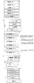
- the A / D unit 12 assigns an ID to each digital data after A / D conversion to generate sensor data.
- the A / D unit 12 When there is a verification request to be described later from the DSP 13, the A / D unit 12 generates sensor data to which a verification flag is assigned (see “Verification F / Data # N + 1” in FIG. 2).
- the sensor data to which the verification flag is assigned is transmitted to the DSP 13 and the CPU 14 respectively.
- “# N + 1”, “# N + 2”,... In FIG. 2 are codes indicating data flows (for example, time series), and are different from the IDs.
- the DSP 13 performs a predetermined calculation process on the sensor data and outputs a calculation result as data indicating a measurement result.
- the DSP 13 adds a verification flag to the calculation result related to the sensor data to which the verification flag is added (see “Checked F / DSP calculation result # N + 1” in FIG. 2).
- CPU14 transmits the calculation result output from DSP13 to the control apparatus 20 as a measurement result.
- the CPU 14 further performs the same calculation process as the predetermined calculation process performed by the DSP 13 on the sensor data on the sensor data to which the verification flag output from the A / D unit 12 is assigned.
- a verification flag is assigned and transmitted to the control device 20 as a verification result (“verification F / verification result # N + 1” in FIG. 2).
- the function of transmitting the measurement result to the control device 20 is referred to as “a transmission processing unit of the CPU 14” for convenience.
- the function of performing verification and transmitting the verification result to the control device 20 is referred to as a “CPU 14 verification processing unit” for convenience.
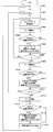
- a / D unit 12 performs A / D conversion on the analog data output from the sensor unit 11 (step S101) and converts the digital data after A / D conversion into digital data.
- An ID is assigned to generate sensor data (step S102).
- the A / D unit 12 determines whether there is a verification request from the DSP 13 (that is, whether a signal indicating a verification request has been received) (step S103). In this determination, if it is determined that there is no verification request (step S103: No), the process of step S106 described later is performed.
- step S103 when it is determined in step S103 that there is a verification request (step S103: Yes), the A / D unit 12 adds a verification flag to the sensor data (step S104). Thereafter, the A / D unit 12 transmits the sensor data to which the verification flag is assigned to the CPU 14 (step S105).
- the A / D unit 12 transmits sensor data (including sensor data to which a verification flag is assigned) to the DSP 13 (step S106).
- the process shown in FIG. 3 is repeatedly performed at a predetermined first period during the operation of the measurement system.
- the DSP 13 is in a standby state until it receives sensor data from the A / D unit 12 (step S201).
- the DSP 13 performs a predetermined calculation process on the received sensor data to generate a calculation result (step S202).
- step S203 determines whether or not a verification flag is given to the sensor data. In this determination, when it is determined that the verification flag is not given (step S203: No), the process of step S205 described later is performed.
- step S203 determines whether the verification flag is given (step S203: Yes) or not. If it is determined in step S203 that the verification flag is given (step S203: Yes), the DSP 13 gives the calculation flag to the calculation result (step S204). Thereafter, the DSP 13 transmits the calculation result (including the calculation result to which the verification flag is assigned) to the CPU 14.
- step S206 determines whether or not there is a verification request from the CPU 14 (that is, whether or not a signal indicating a verification request has been received) (step S206). In this determination, when it is determined that there is no verification request (step S206: No), the processing from step S201 is repeated.
- step S206 determines whether there is a verification request (step S206: Yes). If it is determined in step S206 that there is a verification request (step S206: Yes), the DSP 13 transmits a signal indicating the verification request to the A / D unit 12 (step S207). Thereafter, the processing from step S201 is repeated.
- the transmission processing unit of CPU 14 is in a standby state until it receives a calculation result from DSP 13 (step S301).
- the transmission processing unit of the CPU 14 transmits the calculation result as a measurement result to the control device 20 (step S302).
- the calculation result to which the verification flag is assigned is transmitted to the control device 20 as the measurement result to which the verification flag is assigned. Thereafter, the processing from step S301 is repeated.
- verification processing section of the CPU 14 transmits a signal indicating a verification request to the DSP 13 (step S311). Thereafter, the verification processing unit of the CPU 14 is in a standby state until it receives sensor data to which the verification flag is given from the A / D unit 12 (step S312).
- step S313 When sensor data with a verification flag is received, the verification processing unit of the CPU 14 performs the same arithmetic processing on the received sensor data as the predetermined arithmetic processing performed by the DSP 13 on the sensor data. A result is generated (step S313). Thereafter, the verification processing unit of the CPU 14 adds a verification flag to the generated verification result and transmits it to the control device 20 (step S314). Thereafter, the processing from step S311 is repeated.
- control device 20 is in a standby state until it receives a measurement result or a verification result from the CPU 14 (step S401).
- the control device 20 determines the type of the received data (step S402). In this determination, when it is determined that the measurement result is obtained, the control device 20 determines whether or not a verification flag is given to the received measurement result (step S403). In this determination, when it is determined that the verification flag is not given (step S403: No), the process of step S405 described later is performed.
- step S403 when it is determined that the verification flag has been assigned (step S403: Yes), the control device 20 uses the measurement result to which the verification flag has been assigned as verification comparison data, for example, a memory ( (Not shown) or the like is temporarily stored (step S404).
- control device 20 controls the measurement system based on the measurement result (step S405). Then, it returns to step S401.
- step S402 when it is determined that the result is a verification result, the control device 20 determines whether or not verification comparison data is stored (step S406). In this determination, when it is determined that the verification comparison data is not stored (step S406: No), the process returns to step S401.
- step S406 when it is determined in step S406 that the verification comparison data is stored (step S406: Yes), the control device 20 has the same ID of the verification comparison data and the ID of the received verification result. It is determined whether or not (step S407). In this determination, when it is determined that the IDs are not the same (step S407: No), the process returns to step S401.
- step S407 when it is determined in step S407 that the IDs are the same (step S407: Yes), the control device 20 uses the measurement result to which the verification flag as the verification comparison data is added and the received verification result. Are inconsistent with each other (step S408). In this determination, when it is determined that there is no mismatch (that is, when the measurement result provided with the verification flag matches the verification result) (step S408: No), the measurement system is normal. The process returns to step S401.
- step S408 determines whether they do not match (step S408: Yes). If it is determined in step S408 that they do not match (step S408: Yes), the control device 20 performs a failure determination process such as sounding an alarm, for example (step S409).
- the failure determination process may be set as appropriate.
- the CPU 14 controls the sensor unit 11 and transmits the measurement result and the like to the control device 20 in addition to the generation of the verification result. For this reason, the processing capability of the CPU 14 for generating the verification result is inferior to the processing capability of the DSP 13. If the CPU 14 tries to generate verification results for all sensor data, a period from when one measurement result is generated in the DSP 13 until a verification result corresponding to the one measurement result is generated in the CPU 14. Can be relatively long. Then, for example, there is a possibility that the measurement of the measurement object 30 is continued despite the occurrence of a failure in the measurement apparatus.
- the one measurement result is generated in the CPU 14 after the DSP 13 generates the one measurement result while suppressing the load on the CPU 14.
- the period until the verification result corresponding to is generated can be made relatively short. That is, the real-time property of failure detection can be improved.
- the CPU 14 transmits a signal indicating a verification request to the DSP 13 so that the A / D unit 12 adds a verification flag to the sensor data (S311 in FIG. 6, S206 and S207 in FIG. 4, FIG. 3 (see S103 to S105 of FIG. 3), sensor data that is not processed can be prevented from being accumulated in the CPU.
- the verification process is performed as one of a plurality of processes performed by the CPU 14 in parallel. That is, in this embodiment, in order to detect a failure, another DSP having a processing capability equivalent to that of the DSP 13 is not separately provided, but a part of the processing capability of the CPU 14 is applied to the verification process. For this reason, compared with the case where hardware is duplexed in order to detect a failure, an increase in manufacturing cost and device size can be suppressed.
- a / D conversion”, “predetermined arithmetic processing in the DSP 13”, and “arithmetic processing in the CPU 14” according to the embodiment are respectively “first processing”, “second processing”, and “third processing” according to the present invention.
- the “sensor data”, “calculation result (measurement result)”, “verification result”, and “validation flag” according to the embodiment are “first information”, “second information”, “third information”, and “ It is an example of “additional information”.
- the DSP 13 performs a predetermined calculation process on the sensor data and outputs a calculation result.
- the DSP 13 calculates the calculation result of a part of the calculation process (for example, the first half) (that is, the calculation result indicating intermediate progress: “part of calculation” in FIG. 8). ) ("DSP verification result # N + 1" in FIG. 8).
- the CPU 14 performs the same arithmetic processing as the part of the arithmetic processing performed by the DSP 13 on the sensor data on the sensor data to which the verification flag output from the A / D unit 12 is given, and the obtained result
- the verification result output from the DSP 13 is transmitted as one data to the control device 20 (“DSP / CPU verification result # N + 1” in FIG. 8).
- step S501 when sensor data is received, the DSP 13 performs processing of the first half of the predetermined calculation processing on the received sensor data, and displays a partial calculation result that is a result of the processing of the first half. Generate (step S501).
- step S502 determines whether or not a verification flag is given to the sensor data (step S502). In this determination, when it is determined that the verification flag is not given (step S502: No), the process of step S504 described later is performed.
- step S502 determines whether the verification flag is assigned (step S502: Yes). If it is determined in step S502 that the verification flag is assigned (step S502: Yes), the DSP 13 transmits the partial calculation result to the CPU 14 as the verification result (step S503).
- the DSP 13 performs the latter half of the predetermined calculation process on the received sensor data, and generates a calculation result (step S504). Thereafter, the DSP 13 transmits the calculation result to the CPU 14. Note that the processing in steps S503 and S504 may be performed in parallel.
- the transmission processing unit of the CPU 14 is in a standby state until it receives the calculation result or verification result from the DSP 13 (step S601).
- the transmission processing unit of the CPU 14 determines the type of the received data (Step S602). In this determination, when it is determined that the result is a calculation result, the transmission processing unit of the CPU 14 transmits the calculation result as a measurement result to the control device 20 (step S302). Thereafter, the processing from step S601 is repeated.
- step S602 determines whether the result is a verification result. If it is determined in step S602 that the result is a verification result, the transmission processing unit of the CPU 14 temporarily stores the verification result as a DSP verification result in, for example, a memory (step S603). Thereafter, the processing from step S601 is repeated.
- the verification processing unit of the CPU 14 when sensor data with a verification flag is received, the verification processing unit of the CPU 14 performs predetermined arithmetic processing that the DSP 13 performs on the sensor data with respect to the received sensor data. The same arithmetic processing as the processing in the first half of the above is performed to generate a CPU verification result (step S611).
- step S612 determines whether or not the DSP verification result is stored. In this determination, when it is determined that the DSP verification result is not stored (step S612: No), the process of step S311 is performed.
- step S612 determines whether or not the DSP verification result is stored (step S612: Yes)
- the verification processing unit of the CPU 14 matches the ID of the DSP verification result with the ID of the CPU verification result. It is determined whether or not (step S613). In this determination, when it is determined that the IDs do not match (step S613: No), the process of step S311 is performed.
- step S613 determines whether the IDs match (step S613: Yes)
- the verification processing unit of the CPU 14 sends the DSP verification result and the CPU verification result to the control device 20 as one data. Transmit (step S614). Thereafter, the process of step S311 is performed.
- control device 20 controls the measurement system based on the measurement result (step S405). Then, it returns to step S401.
- step S402 determines whether the result is a verification result.
- the control device 20 determines whether the DSP verification result and the CPU verification result are inconsistent (step S701). In this determination, when it is determined that there is no mismatch (that is, when the DSP verification result and the CPU verification result match) (step S701: No), the measurement system is normal, and the process returns to step S401.
- step S701 determines whether they do not match (step S701: Yes). If it is determined in step S701 that they do not match (step S701: Yes), the control device 20 performs a failure determination process (step S409).
- the first half of the calculation process” and “partial calculation result (DSP verification result)” according to the embodiment are examples of “one part of the second process” and “fourth information” according to the present invention, respectively.
- FIGS. 1 and 2 A third embodiment of the measurement system will be described with reference to FIGS.
- the third embodiment is the same as the second embodiment described above except that part of the processing of the DSP 13 and the CPU 14 is different. Therefore, in the third embodiment, the description overlapping with that of the first and second embodiments is omitted as appropriate, and common portions in the drawing are denoted by the same reference numerals, and only basically different points are shown in FIGS. This will be described with reference to FIG.
- the shaded “data” in FIG. 13 is sensor data to which a verification flag is assigned, and the shaded “calculation A 0 ”, “calculation B 0 ”, and “measurement result” are the first and second implementations, respectively. This is “the verification result by the CPU 14” in the example.
- the arithmetic processing performed by the DSP 13 includes an operation A, an operation B based on the result of the operation A, and an operation C based on the result of the operation B.
- the result of the calculation C corresponds to the calculation result as the measurement result in the first and second embodiments.
- the DSP 13 performs a calculation A on each of a plurality of temporally continuous sensor data, and performs a calculation A 0 , a calculation A 1 ,..., A calculation A M ⁇ 1 (hereinafter, referred to as “multiple sensor data”). (Referred to as “operation A result group”).
- the DSP 13 repeats the operation A to generate a plurality of operation A result groups.
- the DSP 13 generates a calculation B 0 ,..., A calculation B N-1 (hereinafter referred to as “calculation B result group” as appropriate) by a calculation B based on each of the plurality of calculation A result groups.
- the DSP 13 generates a measurement result (calculation result) by a calculation C based on one calculation B result group.
- the DSP 13 When the sensor data to which the verification flag is added is included in the sensor data subjected to the calculation A, the DSP 13 includes a plurality of calculation A result groups used for generating the measurement result related to the sensor data to which the verification flag is added. And the calculation B result group and the measurement result are transmitted to the CPU 14.
- Verification processing part of the CPU14 compared sensor data verification flag is granted outputted from the A / D section 12 performs an operation A, for example, generates an operation A 0.
- Verification processing part of the CPU14 includes an operational A 0 which is the product, the one and computation A 0 which verification flag is generated by the operation A to sensor data attached is performed in the DSP13 data (FIG. 8 To the control device 20 as a “DSP / CPU verification result”.
- the verification processing unit of the CPU 14 calculates the calculation A 0 for the sensor data to which the verification flag is assigned in the DSP 13 among the calculation A 0 generated by the verification processing unit of the CPU 14 and the plurality of calculation A result groups transmitted from the DSP 13.
- the operation B 0 is generated by the operation B based on the operations A 1 ,..., The operation A M ⁇ 1 of the operation A result group including the operation A 0 generated by performing the operation A 0 .
- Verification processing part of the CPU14 includes an operational B 0, which is the product, is transmitted to the control device 20 and an operation B 0 produced by DSP13 as one data (corresponding to "DSP / CPU verification result" in Fig. 8) .
- the verification processing unit of the CPU 14 generates a measurement result by a calculation C based on the calculation B 0 generated by the CPU 14 and the calculations B 1 ,..., Calculation B N ⁇ 1 generated by the DSP 13.
- the verification processing unit of the CPU 14 transmits the generated measurement result and the measurement result generated by the DSP 13 to the control device 20 as one data (corresponding to “DSP / CPU verification result” in FIG. 8).
- the DSP 13 sets the verification result transmission mode to “OFF” (step S801), and whether there is a verification request from the CPU 14 (that is, whether a signal indicating a verification request has been received). Is determined (step S802). In this determination, if it is determined that there is no verification request (step S802: No), the process of step S805 described later is performed.
- step S802 determines whether there is a verification request (step S802: Yes)
- the DSP 13 transmits a signal indicating the verification request to the A / D unit 12 (step S803), and the verification result transmission mode. Is set to “A” (step S804).
- the DSP 13 sets the initial value “0” in the variable j (that is, resets the variable j) (step S805) and sets the initial value “0” in the variable i (that is, resets the variable i). (Step S806).
- the DSP 13 is in a standby state until it receives sensor data from the A / D unit 12 (step S807). If the sensor data is received, DSP 13 performs the operation A to sensor data, for example, it generates an operation A 0 (step S808).
- step S809 determines whether or not the verification flag is given to the sensor data used in the processing of step S808 and the verification result transmission mode is “A” (step S809). In this determination, when it is determined that the verification flag is not given or the verification result transmission mode is not “A” (step S809: No), the process of step S812 described later is performed.
- step S809 If it is determined in step S809 that a verification flag is given and the verification result transmission mode is “A” (step S809: Yes), the DSP 13 performs the operation generated in the processing of step S808. The result of A is transmitted to the CPU 14 for verification A (step S810), and the verification result transmission mode is set to “B” (step S811).
- step S812 the DSP 13 increments the variable i on condition that the variable i is less than the constant M (M is a natural number) (step S812), and repeats the processing after step S807.
- the DSP 13 receives a plurality of results of operation A (for example, the operation B 0 is generated by the operation B based on the operations A 0 to A M ⁇ 1 ) (step S813) (see FIG. 15).
- step S814 determines whether or not the verification result transmission mode is “B” (step S814). In this determination, when it is determined that the verification result transmission mode is not “B” (step S814: No), a process of step S817 described later is performed.
- step S814 determines the result of the operation B generated in the process of step S813 and the operation B.
- the plurality of results of the operation A used in the above are transmitted to the CPU 14 for verification B (step S815), and the verification result transmission mode is set to "C" (step S816).
- the DSP 13 increments the variable j (step S817), and repeats the processing from step S806 on condition that the variable j is less than a constant N (N is a natural number).
- the DSP 13 receives a plurality of results of operation B (for example, A measurement result is generated by calculation C based on calculation B 0 to calculation B N-1 ) (step S818).
- step S819 determines whether or not the verification result transmission mode is “C” (step S819). In this determination, when it is determined that the verification result transmission mode is not “C” (step S819: No), a process of step S822 described later is performed.
- step S819 determines the result of the calculation C generated in step S818 and the calculation C A plurality of results of the operation B used in the above are transmitted to the CPU 14 for verification C (step S820), and the verification result transmission mode is set to “OFF” (step S821).
- the DSP 13 transmits the result of the calculation C generated in the process of step S818 to the CUP 14 as a measurement result (step S822).
- the transmission processing unit of the CPU 14 performs the same processing as the processing shown in FIG. That is, the transmission processing unit of the CPU 14 is in a standby state until it receives a calculation result from the DSP 13 (step S301). When the calculation result is received, the transmission processing unit of the CPU 14 transmits the calculation result as a measurement result to the control device 20 (step S302). Thereafter, the processing from step S301 is repeated.
- the verification processing unit of the CPU 14 first sets STEP as a parameter to “A” (that is, initializes) (step S901). Next, the verification processing unit of the CPU 14 determines what the current STEP is (step S902). In this determination, if it is determined that the current STEP is “A”, the processing of Steps S903 to S909 is performed, and if it is determined that the current STEP is “B”, the processing of Steps S910 to S913 is performed. If it is determined that the current STEP is “C”, steps S914 to S917 are performed.
- the verification processing unit of the CPU 14 transmits a signal indicating a verification request to the DSP 13 (step S903). Thereafter, the verification processing unit of the CPU 14 is in a standby state until it receives sensor data to which the verification flag is given from the A / D unit 12 (step S904).
- verification processing section of the CPU14 is performing an operation A to sensor data with the received, for example, generates an operation A 0 (step S905). Thereafter, the verification processing unit of the CPU 14 is in a standby state until data for verification A is received from the DSP 13 (step S906).
- the verification processing unit of the CPU 14 determines whether or not the received ID of the verification A data matches the ID of the sensor data to which the verification flag is assigned. (Step S907). In this determination, if it is determined that the IDs do not match (step S907: No), the process of step S903 is performed.
- step S907 when it is determined in step S907 that the IDs match (step S907: Yes), the verification processing unit of the CPU 14 determines the result of the calculation A in the processing of step S905 (for example, the calculation A 0 ) and the verification A. Is transmitted to the control device 20 as one data (result of verification A) (step S908), and STEP is set to “B” (step S909).
- the verification processing unit of the CPU 14 When the current STEP is “B”, the verification processing unit of the CPU 14 is in a standby state until it receives data for verification B from the DSP 13 (step S910).
- the verification processing unit of the CPU 14 based on the result of the calculation A in the process of step S905 and the plurality of results of the calculation A by the DSP 13 included in the verification B data. , Operation B is performed, for example, operation B 0 is generated (step S911).
- the verification processing unit of the CPU 14 uses the result of the calculation B in the process of step S911 and the result of the calculation B by the DSP 13 included in the data for the verification B as one data (verification B result). (Step S912), and STEP is set to “C” (step S913).
- the verification processing unit of the CPU 14 is in a standby state until it receives data for verification C from the DSP 13 (step S914).
- the verification processing unit of the CPU 14 based on the result of the calculation B in the process of step S911 and the plurality of results of the calculation B by the DSP 13 included in the data for verification C.
- the calculation C is performed to generate a calculation result (step S915).
- the verification processing unit of the CPU 14 uses the result of the calculation C in the process of step S915 and the result of the calculation C by the DSP 13 included in the data for the verification C as one data (verification C result). (Step S916), and STEP is set to “A” (step S917).
- Example "operation A”, “operation B”, “computing A 0 generated by the DSP 13, ..., operation A M-1”, arithmetic B 0 created by 'DSP 13, ..., computing B N-1 ”,“ Operation A 0 generated by the CPU 14 ”, and“ Operation B 0 generated by the CPU 14 ” are respectively“ process of the first part of the second process ”,“ second of the second process ”according to the present invention. It is an example of “part processing”, “first partial information”, “second partial information”, “third partial information”, and “fourth partial information”.
- FIGS. 1 and 2 A fourth embodiment of the measurement system will be described with reference to FIGS.
- the fourth embodiment is the same as the third embodiment described above except that part of the processing of the DSP 13 and the CPU 14 is different. Therefore, in the fourth embodiment, the description overlapping with the first to third embodiments is omitted as appropriate, and common portions in the drawing are denoted by the same reference numerals, and only the differences are basically shown in FIGS. This will be described with reference to FIG.
- the shaded “data” in FIG. 17 is sensor data to which a verification flag is assigned, and the shaded “calculation A”, “calculation B i ”, and “measurement result” are the first and second embodiments. Is a “verification result by the CPU 14”.
- the DSP 13 sends the result of the calculation A (for example, the calculation A 1 ) to the CPU 14 for the sensor data to which the verification flag is added.
- the verification processing unit of the CPU 14 is configured to control the sensor data output from the A / D unit 12 with the verification flag and the result of the calculation A from the DSP 13 as one data. 20 to send.
- the DSP 13 performs the operation B (for example, the operation B i ) based on the result (for example, the operation A 0 ,..., The operation A M ⁇ 1 ) obtained by performing the operation A on the plurality of sensor data, and the operation A plurality of results of operation A used for B are transmitted to the CPU 14.
- the plurality of results of the calculation A transmitted to the CPU 14 may not include the result of the calculation A for the sensor data to which the verification flag is assigned.
- the verification processing unit of the CPU 14 transmits the result of the operation B (for example, the operation B i ) based on the plurality of results of the operation A from the DSP 13 and the result of the operation B from the DSP 13 to the control device 20 as one data. To do.
- the DSP 13 calculates the result (measurement result) of the operation C based on a plurality of results of the operation B (for example, the operations B 0 ,..., The operation B N ⁇ 1 ) and the plurality of operations B used for the operation C. Are sent to the CPU 14.
- the verification processing unit of the CPU 14 transmits the result of the calculation C based on the plurality of results of the calculation B from the DSP 13 and the result of the calculation C from the DSP 13 to the control device 20 as one data.
- step S1001 determines whether or not a verification flag is added to the sensor data used for the process of step S808 (step S1001). In this determination, when it is determined that the verification flag is not given (step S1001: No), the process of step S1002 described later is performed. On the other hand, in this determination, when it is determined that the verification flag is given (step S1001: Yes), the DSP 13 performs the process of step S810.
- step S1002 determines whether there is a verification A request from the CPU 14 (that is, whether a signal indicating the verification A request has been received) (step S1002). In this determination, when it is determined that there is no verification A request (step S1002: No), the process of step S812 is performed. On the other hand, in this determination, when it is determined that there is a verification A request (step S1002: Yes), the DSP 13 transmits a signal indicating the verification A request to the A / D unit 12 (step S1003).
- step S1004 determines whether there is a verification B request from the CPU 14 (that is, whether a signal indicating the verification B request has been received) (step S1004). In this determination, when it is determined that there is no check B request (step S1004: No), the process of step S817 is performed. On the other hand, in this determination, when it is determined that there is a check B request (step S1004: Yes), the DSP 13 performs the process of step S815.
- step S818 the DSP 13 determines whether there is a verification C request from the CPU 14 (that is, whether a signal indicating the verification C request has been received) (step S1005). In this determination, when it is determined that there is no verification C request (step S1005: No), the process of step S822 is performed. On the other hand, in this determination, when it is determined that there is a check C request (step S1005: Yes), the DSP 13 performs the process of step S820.
- the transmission processing unit of the CPU 14 performs the same processing as the processing shown in FIG. That is, the transmission processing unit of the CPU 14 is in a standby state until it receives a calculation result from the DSP 13 (step S301). When the calculation result is received, the transmission processing unit of the CPU 14 transmits the calculation result as a measurement result to the control device 20 (step S302). Thereafter, the processing from step S301 is repeated.
- the verification processing unit of the CPU 14 transmits a signal indicating the verification B request to the DSP 13 (step S1102). Thereafter, the verification processing unit of the CPU 14 performs the processing after step S910.
- the verification processing unit of the CPU 14 transmits a signal indicating the verification C request to the DSP 13 (step S1103). Thereafter, the verification processing unit of the CPU 14 performs the processing after step S914.
- a fifth embodiment of the measurement system will be described with reference to FIGS.
- the measurement system according to the fifth embodiment differs from the measurement system according to the first embodiment described above in that sensor data is transmitted to the CPU 14 via the DSP 13.
- the other configuration is substantially the same as that of the first embodiment. Therefore, in the fifth embodiment, the description overlapping with that of the first embodiment is omitted as appropriate, and common portions in the drawing are denoted by the same reference numerals, and FIGS. The description will be given with reference.
- FIG. 21 is a block diagram showing the configuration of the measurement system according to the fifth example.
- the measurement system is configured to include a measurement device 10a as another example of the information processing device according to the present invention and a control device 20.
- the measuring device 10a includes a sensor unit 11, an A / D unit 12, a DSP 13, and a CPU.
- the CPU 14 acquires the sensor data output from the A / D unit 12 via the DSP 13, and uses the acquired sensor data to simulate the processing in the DSP 13 (for details). Will be described later).
- the A / D unit 12 performs A / D conversion on the analog data output from the sensor unit 11 to generate sensor data as digital data.
- the generated sensor data is sequentially output to the DSP 13.
- the DSP 13 assigns an ID to each sensor data output from the A / D unit 12.
- the DSP 13 performs a predetermined calculation process on the sensor data, and outputs a calculation result as data indicating a measurement result.
- the same ID as the ID assigned to the sensor data that is the basis of the calculation result is assigned to the calculation result.
- the DSP 13 outputs sensor data (“data via DSP # N + 1” in FIG. 22) used when the processing in the DSP 13 is simulated by the CPU 14 to the CPU 14 and performs predetermined arithmetic processing on the sensor data.
- the verification flag is added to the calculation result generated by applying (Check F / DSP calculation result # N + 1 ”in FIG. 22).
- CPU14 transmits the calculation result output from DSP13 to the control apparatus 20 as a measurement result.
- the CPU 14 further performs the same calculation process as the predetermined calculation process performed by the DSP 13 on the sensor data on the sensor data acquired via the DSP 13, and adds a verification flag to the obtained result, and the verification result ("Verification F / Verification result # N + 1" in FIG. 22) is transmitted to the control device 20.
- a / D unit 12 performs A / D conversion on the analog data output from the sensor unit 11 to generate sensor data (step S1201).
- the A / D unit 12 transmits the sensor data to the DSP 13 (step S1202).
- the process shown in FIG. 23 is repeatedly performed at a predetermined first period during the operation of the measurement system.
- the DSP 13 is in a standby state until it receives sensor data from the A / D unit 12 (step S1301).
- the DSP 13 gives an ID to the received sensor data (step S1302).
- the DSP 13 performs a predetermined calculation process on the sensor data to which the ID is assigned, and generates a calculation result (step S1303).
- step S1304 determines whether there is a verification request from the CPU 14 (that is, whether a signal indicating a verification request has been received) (step S1304). In this determination, if it is determined that there is no verification request (step S1304: No), the process of step S1307 described later is performed.
- step S1304 determines whether there is a verification request (step S1304: Yes)
- the DSP 13 transmits the sensor data to which the ID is assigned in the process of step S1302 to the CPU 14 (step S1305).
- a verification flag is assigned to the calculation result generated by performing predetermined calculation processing on the sensor data transmitted to the CPU 14 (step S1306).
- the DSP 13 transmits sensor data to the CPU 14 when there is a verification request from the CPU 14. That is, the DSP 13 typically transmits part of the sensor data received from the A / D unit 12 to the CPU 14.
- the DSP 13 assigns the same ID as the ID assigned to the sensor data that is the source of the computation result to the computation result (including the computation result to which the verification flag is assigned), and the computation to which the ID is assigned.
- the result is transmitted to the CPU 14 (step S1307). Thereafter, the processing from step S1301 is repeated.
- the transmission processing unit of the CPU 14 performs the same processing as the processing shown in FIG. That is, the transmission processing unit of the CPU 14 is in a standby state until it receives a calculation result from the DSP 13 (step S301). When the calculation result is received, the transmission processing unit of the CPU 14 transmits the calculation result as a measurement result to the control device 20 (step S302). Thereafter, the processing from step S301 is repeated.
- Verification processing of the CPU 14 The verification processing unit of the CPU 14 according to the fifth embodiment performs the same processing as the processing shown in FIG. That is, the verification processing unit of the CPU 14 transmits a signal indicating a verification request to the DSP 13 (step S311). Thereafter, the verification processing unit of the CPU 14 is in a standby state until sensor data is received from the DSP 13 (step S312).
- the verification processing unit of the CPU 14 When the sensor data is received, the verification processing unit of the CPU 14 performs the same arithmetic processing as the predetermined arithmetic processing that the DSP 13 performs on the sensor data on the received sensor data to generate a verification result (Step S1). S313). Thereafter, the verification processing unit of the CPU 14 adds a verification flag to the generated verification result and transmits it to the control device 20 (step S314). Thereafter, the processing from step S311 is repeated.
- control device 20 performs the same processing as the processing shown in FIG. That is, the control device 20 is in a standby state until it receives a measurement result or a verification result from the CPU 14 (step S401).
- the control device 20 determines the type of the received data (step S402). In this determination, when it is determined that the measurement result is obtained, the control device 20 determines whether or not a verification flag is given to the received measurement result (step S403). In this determination, when it is determined that the verification flag is not given (step S403: No), the process of step S405 described later is performed.
- step S403 when it is determined that the verification flag has been assigned (step S403: Yes), the control device 20 uses the measurement result to which the verification flag has been assigned as verification comparison data, for example, a memory ( (Not shown) or the like is temporarily stored (step S404).
- control device 20 controls the measurement system based on the measurement result (step S405). Then, it returns to step S401.
- step S402 when it is determined that the result is a verification result, the control device 20 determines whether or not verification comparison data is stored (step S406). In this determination, when it is determined that the verification comparison data is not stored (step S406: No), the process returns to step S401.
- step S406 when it is determined in step S406 that the verification comparison data is stored (step S406: Yes), the control device 20 has the same ID of the verification comparison data and the ID of the received verification result. It is determined whether or not (step S407). In this determination, when it is determined that the IDs are not the same (step S407: No), the process returns to step S401.
- step S407 when it is determined in step S407 that the IDs are the same (step S407: Yes), the control device 20 uses the measurement result to which the verification flag as the verification comparison data is added and the received verification result. Are inconsistent with each other (step S408). In this determination, when it is determined that there is no mismatch (that is, when the measurement result provided with the verification flag matches the verification result) (step S408: No), the measurement system is normal. The process returns to step S401.
- step S408 when it is determined in step S408 that they do not match (step S408: Yes), the control device 20 performs a failure determination process (step S409).
- FIGS. A sixth embodiment of the measurement system will be described with reference to FIGS.
- the measurement system according to the sixth embodiment is the same as that of the fifth embodiment described above except that some of the processes of the DSP 13, the CPU 14, and the control device 20 are different. Accordingly, in the sixth embodiment, the description overlapping with that of the fifth embodiment will be omitted as appropriate, and the same reference numerals will be given to the common parts in the drawings, and FIGS. The description will be given with reference.
- the DSP 13 performs a predetermined calculation process on the sensor data and outputs a calculation result.
- the DSP 13 calculates the calculation result of a part of the calculation process (for example, the first half) (that is, the calculation result indicating intermediate progress: “part of calculation” in FIG. 25).
- the calculation result # N + 1 that is, the calculation result indicating intermediate progress: “part of calculation” in FIG. 25).
- the DSP 13 divides the sensor data transmitted to the CPU 14 into M pieces, and then sequentially transmits the divided sensor data to the CPU 14 ("data # N + 1 (M / M in FIG. 25)". ) "," Data # N + 1 (M-1 / M) ", ).
- the divided sensor data according to the present embodiment is an example of “sixth partial information” according to the present invention.
- the CPU 14 acquires the sensor data output from the A / D unit 12 via the DSP 13, and uses the acquired sensor data to perform the same calculation as part of the above calculation process performed by the DSP 13 on the sensor data. Processing is performed, and the obtained result and the verification result output from the DSP 13 are transmitted as one data to the control device 20 (“DSP / CPU verification result # N + 1” in FIG. 25).
- the DSP 13 first sets an initial value “0” to a variable i (that is, resets the variable i) (step S1401).
- the DSP 13 is in a standby state until it receives sensor data from the A / D unit 12 (step S1402).
- the DSP 13 When the sensor data is received, the DSP 13 performs the first half of the predetermined calculation process on the received sensor data, and generates a partial calculation result that is the result of the first half process (step S1403).
- step S1404 determines whether or not there is a verification request from the CPU 14 (that is, whether or not a signal indicating the verification request has been received) (step S1404). In this determination, if it is determined that there is no verification request (step S1404: No), the process of step S1408 described later is performed.
- step S1404 determines whether there is a verification request (step S1404: Yes)
- the DSP 13 transmits the partial calculation result generated in the process of step S1403 to the CPU 14 as the verification result (step S1405).
- the DSP 13 divides and stores the sensor data used for generating the partial calculation result as the verification result into M verification data buffers (step S1406) and sets “M” to the variable i. (Step S1407).
- the DSP 13 performs the latter half of the predetermined calculation process on the received sensor data, and generates a calculation result (step S1408). Next, the DSP 13 transmits the calculation result to the CPU 14.
- step S1410 determines whether or not the variable i is greater than 0 (step S1410). In this determination, when it is determined that the variable i is 0 or less (step S1410: No), the processing from step S1402 is repeated.
- step S1410 determines whether the variable i is greater than 0 (step S1410: Yes)
- the DSP 13 transmits data corresponding to the value of the variable i in the verification data buffer to the CPU 14 (step S1411), and the variable i is not displayed. It is incremented (step S1412). Thereafter, the processing from step S1402 is repeated.
- the transmission processing unit of the CPU 14 performs the same processing as the processing shown in FIG. That is, the transmission processing unit of the CPU 14 is in a standby state until it receives a calculation result or a verification result from the DSP 13 (step S601).
- the transmission processing unit of the CPU 14 determines the type of the received data (Step S602). In this determination, when it is determined that the result is a calculation result, the transmission processing unit of the CPU 14 transmits the calculation result as a measurement result to the control device 20 (step S302). Thereafter, the processing from step S601 is repeated.
- step S602 determines whether the result is a verification result. If it is determined in step S602 that the result is a verification result, the transmission processing unit of the CPU 14 temporarily stores the verification result as a DSP verification result in, for example, a memory (step S603). Thereafter, the processing from step S601 is repeated.
- the verification processing unit of the CPU 14 transmits a signal indicating a verification request to the DSP 13 (step S1501). Thereafter, the verification processing unit of the CPU 14 is in a standby state until sensor data is received from the DSP 13 (step S1502).
- step S1503 the verification processing unit of the CPU 14 determines whether all of the divided sensor data has been received. In this determination, when it is determined that all the divided sensor data has not been received (step S1503: No), the processing from step S1502 is repeated.
- step S1503 determines whether all of the divided sensor data has been received (step S1503: Yes). If it is determined in step S1503 that all of the divided sensor data has been received (step S1503: Yes), the CPU 14 applies the sensor data to the received sensor data. The same arithmetic processing as the first half of the predetermined arithmetic processing is performed to generate a CPU verification result (step S1504).
- step S1505 determines whether or not the DSP verification result is stored. In this determination, when it is determined that the DSP verification result is not stored (step S1505: No), the process of step S1501 is performed.
- step S1505 determines whether the DSP verification result is stored (step S1505: Yes) or not. If it is determined in step S1505 that the DSP verification result is stored (step S1505: Yes), the verification processing unit of the CPU 14 controls the DSP verification result and the CPU verification result as one data. 20 (step S1506). Thereafter, the process of step S1501 is performed.
- control device 20 performs the same process as the process shown in FIG. That is, in FIG. 12, when it is determined in step S402 that the measurement result is obtained, the control device 20 controls the measurement system based on the measurement result (step S405). Then, it returns to step S401.
- step S402 determines whether the result is a verification result.
- the control device 20 determines whether the DSP verification result and the CPU verification result are inconsistent (step S701). In this determination, when it is determined that there is no mismatch (that is, when the DSP verification result and the CPU verification result match) (step S701: No), the measurement system is normal, and the process returns to step S401.
- step S701 determines whether they do not match (step S701: Yes). If it is determined in step S701 that they do not match (step S701: Yes), the control device 20 performs a failure determination process (step S409).
- FIGS. 28 to 30 A seventh embodiment of the measurement system will be described with reference to FIGS.
- the seventh embodiment is the same as the fifth embodiment described above except that part of the processing of the DSP 13 and the CPU 14 is different. Therefore, in the seventh embodiment, the description overlapping with that of the fifth embodiment is omitted as appropriate, and the same reference numerals are given to the common portions in the drawings, and FIGS. 28 to 30 are basically different only. The description will be given with reference.
- the shaded “calculation A” in FIG. 28 is obtained by adding a verification flag to the result of performing computation A on the sensor data (shaded “data” in FIG. 28) transmitted to the CPU 14 via the DSP 13. It is.
- Each of the shaded “calculation A”, “calculation B”, and “measurement result” is a “verification result by the CPU 14” in the fifth embodiment.
- the DSP 13 assigns a verification flag to the result of calculation A (for example, calculation A i ) for the sensor data transmitted to the CPU 14 among the received sensor data, and transmits the result to the CPU 14.
- the verification processing unit of the CPU 14 transmits the result of the operation A performed on the sensor data acquired via the DSP 13 and the result of the operation A from the DSP 13 to the control device 20 as one data.
- the DSP 13 performs the operation B (for example, the operation B i ) based on the result (for example, the operation A 0 ,..., The operation A M ⁇ 1 ) obtained by performing the operation A on the plurality of sensor data, and the operation A plurality of results of operation A used for B are transmitted to the CPU 14.
- the verification processing unit of the CPU 14 transmits the result of the operation B (for example, the operation B) based on the plurality of results of the operation A from the DSP 13 and the result of the operation B from the DSP 13 to the control device 20 as one data. .
- the DSP 13 calculates the result (measurement result) of the operation C based on a plurality of results of the operation B (for example, the operations B 0 ,..., The operation B N ⁇ 1 ) and the plurality of operations B used for the operation C. Are sent to the CPU 14.
- the verification processing unit of the CPU 14 transmits the result of the calculation C based on the plurality of results of the calculation B from the DSP 13 and the result of the calculation C from the DSP 13 to the control device 20 as one data.
- the DSP 13 sets an initial value “0” in a variable j (that is, resets the variable j) (step S1601), and sets an initial value “0” in the variable i ( That is, the variable i is reset) (step S1602).
- the DSP 13 is in a standby state until it receives sensor data from the A / D unit 12 (step S1603). If the sensor data is received, DSP 13 performs the operation A to sensor data, for example, it generates an operation A 1 (step S1604).
- step S1605 determines whether or not there is a verification A request from the CPU 14 (that is, whether or not a signal indicating the verification A request has been received) (step S1605). In this determination, when it is determined that there is no verification A request (step S1605: No), the process of step S1607 described later is performed. On the other hand, in this determination, when it is determined that there is a check A request (step S1605: Yes), the DSP 13 determines the result of the operation A generated in the process of step S1604 and the sensor data used for the operation A. Is transmitted to the CPU 14 for verification A (step S1606).
- the DSP 13 increments the variable i on condition that the variable i is less than the constant M (M is a natural number) (step S1607), and repeats the processing after step S1603.
- the DSP 13 receives a plurality of results of the operation A (for example, the operation B i is generated by the operation B based on the operations A 0 to A M ⁇ 1 ) (step S1608).
- the DSP 13 determines whether or not there is a verification B request from the CPU 14 (that is, whether or not a signal indicating the verification B request has been received) (step S1609). In this determination, if it is determined that there is no verification B request (step S1609: No), the process of step S1611 described later is performed. On the other hand, in this determination, when it is determined that there is a check B request (step S1609: Yes), the DSP 13 determines the result of the operation B generated in the process of step S1608 and the operation A used for the operation B. A plurality of results are transmitted to CPU 14 for verification B (step S1610).
- the DSP 13 increments the variable j (step S1611) on the condition that the variable j is less than the constant N (N is a natural number), and repeats the processing after step S1602.
- the DSP 13 When the variable j is equal to or greater than the constant N (that is, after the results of Steps S1602 to S1608 are repeatedly performed to generate a plurality of results of the operation B), the DSP 13 outputs a plurality of results of the operation B (for example, A measurement result is generated by calculation C based on calculation B 0 to calculation B N-1 ) (step S1612).
- the DSP 13 determines whether or not there is a verification C request from the CPU 14 (that is, whether or not a signal indicating the verification C request has been received) (step S1613). In this determination, if it is determined that there is no verification C request (step S1613: No), the process of step S1615 described later is performed. On the other hand, in this determination, when it is determined that there is a check C request (step S1613: Yes), the DSP 13 determines the result of the operation C generated in the process of step S1612 and the operation B used for the operation C. A plurality of results are transmitted to the CPU 14 for verification C (step S1614).
- the DSP 13 transmits the result of the operation C generated in the process of step S1612 as a measurement result to the CPU 14 (step S1615).
- the transmission processing unit of the CPU 14 performs the same processing as the processing shown in FIG. That is, the transmission processing unit of the CPU 14 is in a standby state until it receives a calculation result from the DSP 13 (step S301). When the calculation result is received, the transmission processing unit of the CPU 14 transmits the calculation result as a measurement result to the control device 20 (step S302). Thereafter, the processing from step S301 is repeated.
- the verification processing unit of the CPU 14 first sets STEP as a parameter to “A” (that is, initializes) (step S1701). Next, the verification processing unit of the CPU 14 determines what the current STEP is (step S1702). In this determination, if it is determined that the current STEP is “A”, the processing in steps S1703 to S1707 is performed. If it is determined that the current STEP is “B”, the processing in steps S1708 to S1712 is performed. When it is determined that the current STEP is “C”, the processing of steps S1713 to S1717 is performed.
- the verification processing unit of the CPU 14 transmits a signal indicating the verification A request to the DSP 13 (step S1703). Thereafter, the verification processing unit of the CPU 14 is in a standby state until data for verification A is received from the DSP 13 (step S1704).
- the verification processing unit of the CPU 14 performs calculation A on the sensor data included in the received data for verification A to generate, for example, calculation A 1 (step S1705). ).
- the verification processing unit of the CPU 14 transmits the result of the calculation A in the process of step S1705 and the result of the calculation A by the DSP 13 included in the data for verification A to the control device 20 as one data (step S1706). ), STEP is set to “B” (step S1707).
- the verification processing unit of the CPU 14 transmits a signal indicating the verification B request to the DSP 13 (step S1708). Thereafter, the verification processing unit of the CPU 14 is in a standby state until data for verification B is received from the DSP 13 (step S1709). When the verification B data is received, the verification processing unit of the CPU 14 performs the calculation B based on a plurality of results of the calculation A by the DSP 13 included in the received verification B data. i is generated (step S1710).
- the verification processing unit of the CPU 14 transmits the result of the calculation B in the process of step S1710 and the result of the calculation B by the DSP 13 included in the data for the verification B as one data to the control device 20 (step S1711), STEP is set to “C” (step S1712).
- the verification processing unit of the CPU 14 transmits a signal indicating the verification C request to the DSP 13 (step S1713). Thereafter, the verification processing unit of the CPU 14 is in a standby state until it receives data for verification C from the DSP 13 (step S1714). When the verification C data is received, the verification processing unit of the CPU 14 performs the calculation C based on a plurality of results of the calculation B by the DSP 13 included in the received verification C data, and the calculation result is obtained. Generate (step S1715).
- step S1715 the verification processing unit of the CPU 14 transmits the result of the calculation C in the process of step S1715 and the result of the calculation C by the DSP 13 included in the data for the verification C as one data to the control device 20 (step S1715).
- step S1716 STEP is set to “A” (step S1717).
Landscapes
- Engineering & Computer Science (AREA)
- Theoretical Computer Science (AREA)
- General Engineering & Computer Science (AREA)
- Physics & Mathematics (AREA)
- General Physics & Mathematics (AREA)
- Quality & Reliability (AREA)
- Computer Hardware Design (AREA)
- Automation & Control Theory (AREA)
- Arrangements For Transmission Of Measured Signals (AREA)
- Retry When Errors Occur (AREA)
- Testing Or Calibration Of Command Recording Devices (AREA)
Abstract
L'invention concerne un dispositif de traitement d'informations (10) comprenant : une première unité de traitement (12) qui génère des premières informations en effectuant un premier traitement par rapport à des informations de capteur acquises par un capteur (11) ; une deuxième unité de traitement (13) qui génère des secondes informations en effectuant, par rapport aux premières informations, un deuxième traitement qui est différent du premier traitement ; et une troisième unité de traitement (14) qui génère des troisièmes informations en effectuant, par rapport aux premières informations, un troisième traitement, c'est-à-dire un traitement qui correspond à au moins une partie du deuxième traitement et qui acquiert les deuxièmes informations, puis génère les deuxièmes informations et les troisièmes informations.
Priority Applications (4)
| Application Number | Priority Date | Filing Date | Title |
|---|---|---|---|
| EP17900036.9A EP3594815A4 (fr) | 2017-03-09 | 2017-03-09 | Dispositif de traitement d'informations, procédé de traitement d'informations, programme informatique et support d'enregistrement |
| JP2019504239A JP6906603B2 (ja) | 2017-03-09 | 2017-03-09 | 情報処理装置及び方法、コンピュータプログラム並びに記録媒体 |
| PCT/JP2017/009558 WO2018163371A1 (fr) | 2017-03-09 | 2017-03-09 | Dispositif de traitement d'informations, procédé de traitement d'informations, programme informatique et support d'enregistrement |
| US16/492,339 US11080119B2 (en) | 2017-03-09 | 2017-03-09 | Information processing with failure detection, apparatus and method |
Applications Claiming Priority (1)
| Application Number | Priority Date | Filing Date | Title |
|---|---|---|---|
| PCT/JP2017/009558 WO2018163371A1 (fr) | 2017-03-09 | 2017-03-09 | Dispositif de traitement d'informations, procédé de traitement d'informations, programme informatique et support d'enregistrement |
Publications (1)
| Publication Number | Publication Date |
|---|---|
| WO2018163371A1 true WO2018163371A1 (fr) | 2018-09-13 |
Family
ID=63448072
Family Applications (1)
| Application Number | Title | Priority Date | Filing Date |
|---|---|---|---|
| PCT/JP2017/009558 Ceased WO2018163371A1 (fr) | 2017-03-09 | 2017-03-09 | Dispositif de traitement d'informations, procédé de traitement d'informations, programme informatique et support d'enregistrement |
Country Status (4)
| Country | Link |
|---|---|
| US (1) | US11080119B2 (fr) |
| EP (1) | EP3594815A4 (fr) |
| JP (1) | JP6906603B2 (fr) |
| WO (1) | WO2018163371A1 (fr) |
Citations (8)
| Publication number | Priority date | Publication date | Assignee | Title |
|---|---|---|---|---|
| JPH01280839A (ja) * | 1987-12-04 | 1989-11-13 | Hitachi Ltd | 半導体集積回路装置 |
| JP2002247012A (ja) * | 2001-02-15 | 2002-08-30 | Nippon Signal Co Ltd:The | バス照合回路 |
| WO2004057313A1 (fr) | 2002-12-20 | 2004-07-08 | Optoq Ab | Procede et dispositif pour effectuer des mesures sanguines |
| JP2006228002A (ja) | 2005-02-18 | 2006-08-31 | Japan Aviation Electronics Industry Ltd | 故障検知機能付き二重系システム |
| JP2011128821A (ja) * | 2009-12-17 | 2011-06-30 | Yokogawa Electric Corp | 二重化フィールド機器 |
| WO2012120578A1 (fr) * | 2011-03-10 | 2012-09-13 | 三菱電機株式会社 | Dispositif redondant |
| WO2013153664A1 (fr) | 2012-04-13 | 2013-10-17 | パイオニア株式会社 | Procédé et dispositif d'évaluation d'un fluide |
| JP2016085162A (ja) * | 2014-10-28 | 2016-05-19 | 株式会社日立製作所 | 半導体集積回路、半導体集積回路の故障検出方法および電子装置 |
Family Cites Families (9)
| Publication number | Priority date | Publication date | Assignee | Title |
|---|---|---|---|---|
| US5043990A (en) | 1987-12-04 | 1991-08-27 | Hitachi, Ltd. | Semiconductor integrated circuit device |
| AU625293B2 (en) * | 1988-12-09 | 1992-07-09 | Tandem Computers Incorporated | Synchronization of fault-tolerant computer system having multiple processors |
| CA2059143C (fr) * | 1991-01-25 | 2000-05-16 | Takeshi Miyao | Unite de traitement pour ordinateur et ordinateur comportant cette unite |
| DE10361465A1 (de) * | 2003-12-23 | 2005-08-11 | Endress + Hauser Gmbh + Co. Kg | Prozessmessgerät mit erweiterter Hardwarefehlererkennung |
| JP4487640B2 (ja) * | 2004-06-01 | 2010-06-23 | ソニー株式会社 | 撮像装置 |
| WO2007032226A1 (fr) * | 2005-09-15 | 2007-03-22 | Citizen Holdings Co., Ltd. | Instrument de mesure du rythme cardiaque et procédé permettant d'enlever un bruit de la forme d’onde du rythme cardiaque |
| GB2555627B (en) * | 2016-11-04 | 2019-02-20 | Advanced Risc Mach Ltd | Error detection |
| GB2559122B (en) * | 2017-01-24 | 2020-03-11 | Advanced Risc Mach Ltd | Error detection using vector processing circuitry |
| JP7217153B2 (ja) * | 2019-01-10 | 2023-02-02 | 富士通株式会社 | 情報処理装置、時刻同期方法、及び時刻同期プログラム |
-
2017
- 2017-03-09 WO PCT/JP2017/009558 patent/WO2018163371A1/fr not_active Ceased
- 2017-03-09 JP JP2019504239A patent/JP6906603B2/ja active Active
- 2017-03-09 US US16/492,339 patent/US11080119B2/en active Active
- 2017-03-09 EP EP17900036.9A patent/EP3594815A4/fr active Pending
Patent Citations (8)
| Publication number | Priority date | Publication date | Assignee | Title |
|---|---|---|---|---|
| JPH01280839A (ja) * | 1987-12-04 | 1989-11-13 | Hitachi Ltd | 半導体集積回路装置 |
| JP2002247012A (ja) * | 2001-02-15 | 2002-08-30 | Nippon Signal Co Ltd:The | バス照合回路 |
| WO2004057313A1 (fr) | 2002-12-20 | 2004-07-08 | Optoq Ab | Procede et dispositif pour effectuer des mesures sanguines |
| JP2006228002A (ja) | 2005-02-18 | 2006-08-31 | Japan Aviation Electronics Industry Ltd | 故障検知機能付き二重系システム |
| JP2011128821A (ja) * | 2009-12-17 | 2011-06-30 | Yokogawa Electric Corp | 二重化フィールド機器 |
| WO2012120578A1 (fr) * | 2011-03-10 | 2012-09-13 | 三菱電機株式会社 | Dispositif redondant |
| WO2013153664A1 (fr) | 2012-04-13 | 2013-10-17 | パイオニア株式会社 | Procédé et dispositif d'évaluation d'un fluide |
| JP2016085162A (ja) * | 2014-10-28 | 2016-05-19 | 株式会社日立製作所 | 半導体集積回路、半導体集積回路の故障検出方法および電子装置 |
Non-Patent Citations (1)
| Title |
|---|
| See also references of EP3594815A4 * |
Also Published As
| Publication number | Publication date |
|---|---|
| JPWO2018163371A1 (ja) | 2020-01-09 |
| US11080119B2 (en) | 2021-08-03 |
| JP6906603B2 (ja) | 2021-07-21 |
| US20210133016A1 (en) | 2021-05-06 |
| EP3594815A4 (fr) | 2021-03-24 |
| EP3594815A1 (fr) | 2020-01-15 |
Similar Documents
| Publication | Publication Date | Title |
|---|---|---|
| CY1125246T1 (el) | Συστημα και μεθοδος για τη λειτουργια ενος ηλεκτροχημικου αισθητηρα αναλυτη | |
| CN107110829B (zh) | 用于测试声探头的透镜和所选择的换能器元件的可操作性的系统及方法 | |
| JP2018165732A5 (fr) | ||
| CA2990840A1 (fr) | Marquage pps de donnees d'echantillon acoustique | |
| JP2010281771A (ja) | 同期記録システム及び同期記録方法 | |
| NO20100342L (no) | Teknikk og system for a behandle et seismisk signal for a bestemme en attributt ved et geologisk lag | |
| WO2012049613A3 (fr) | Dispositif, méthode et système de test d'instruments financiers dérivés | |
| CN115347972A (zh) | 声呐时钟同步方法、装置、设备及存储介质 | |
| WO2019185520A3 (fr) | Dispositif de détection pour un véhicule | |
| CA2858306C (fr) | Systeme d'imagerie ultrasonore et dispositif de traitement utilise a l'interieur dudit systeme d'imagerie ultrasonore | |
| JP6906603B2 (ja) | 情報処理装置及び方法、コンピュータプログラム並びに記録媒体 | |
| JP2015025797A5 (fr) | ||
| JP2015162194A5 (fr) | ||
| Szymoniak et al. | Overview of Modern Technologies for Acquiring and Analysing Acoustic Information Based on AI and IoT | |
| KR20160090428A (ko) | 주변 센싱 정보에 대한 가격 입찰을 통해 노출 광고를 결정하는 방법 및 시스템 | |
| JP7224882B2 (ja) | センサシステム、センサシステムの制御方法、及び制御装置 | |
| US11226217B2 (en) | Field device, system, and waveform data output method | |
| EP2857805B1 (fr) | Dispositif de champ | |
| US20220358953A1 (en) | Sound model generation device, sound model generation method, and recording medium | |
| CN110988840B (zh) | 飞行时间的获取方法、装置及电子设备 | |
| US20200364296A1 (en) | Prescan device activation prevention | |
| CN114440888B (zh) | 基于序列分组滑动窗口的室内定位方法及装置 | |
| CN116295552B (zh) | 光栅阵列传感网络及分布式传感信息的获取方法 | |
| CN109655735A (zh) | 功放芯片评估板以及功放芯片评估板系统 | |
| US9454418B1 (en) | Method for testing capability of dissimilar processors to achieve identical computations |
Legal Events
| Date | Code | Title | Description |
|---|---|---|---|
| 121 | Ep: the epo has been informed by wipo that ep was designated in this application |
Ref document number: 17900036 Country of ref document: EP Kind code of ref document: A1 |
|
| ENP | Entry into the national phase |
Ref document number: 2019504239 Country of ref document: JP Kind code of ref document: A |
|
| NENP | Non-entry into the national phase |
Ref country code: DE |
|
| ENP | Entry into the national phase |
Ref document number: 2017900036 Country of ref document: EP Effective date: 20191009 |