WO2018173485A1 - 液体処理装置 - Google Patents
液体処理装置 Download PDFInfo
- Publication number
- WO2018173485A1 WO2018173485A1 PCT/JP2018/002741 JP2018002741W WO2018173485A1 WO 2018173485 A1 WO2018173485 A1 WO 2018173485A1 JP 2018002741 W JP2018002741 W JP 2018002741W WO 2018173485 A1 WO2018173485 A1 WO 2018173485A1
- Authority
- WO
- WIPO (PCT)
- Prior art keywords
- electrode
- liquid
- central axis
- processing apparatus
- plasma
- Prior art date
- Legal status (The legal status is an assumption and is not a legal conclusion. Google has not performed a legal analysis and makes no representation as to the accuracy of the status listed.)
- Ceased
Links
Images






Classifications
-
- C—CHEMISTRY; METALLURGY
- C02—TREATMENT OF WATER, WASTE WATER, SEWAGE, OR SLUDGE
- C02F—TREATMENT OF WATER, WASTE WATER, SEWAGE, OR SLUDGE
- C02F1/00—Treatment of water, waste water, or sewage
- C02F1/46—Treatment of water, waste water, or sewage by electrochemical methods
- C02F1/4608—Treatment of water, waste water, or sewage by electrochemical methods using electrical discharges
-
- C—CHEMISTRY; METALLURGY
- C02—TREATMENT OF WATER, WASTE WATER, SEWAGE, OR SLUDGE
- C02F—TREATMENT OF WATER, WASTE WATER, SEWAGE, OR SLUDGE
- C02F1/00—Treatment of water, waste water, or sewage
- C02F1/008—Control or steering systems not provided for elsewhere in subclass C02F
-
- C—CHEMISTRY; METALLURGY
- C02—TREATMENT OF WATER, WASTE WATER, SEWAGE, OR SLUDGE
- C02F—TREATMENT OF WATER, WASTE WATER, SEWAGE, OR SLUDGE
- C02F1/00—Treatment of water, waste water, or sewage
- C02F1/30—Treatment of water, waste water, or sewage by irradiation
- C02F1/32—Treatment of water, waste water, or sewage by irradiation with ultraviolet light
-
- C—CHEMISTRY; METALLURGY
- C02—TREATMENT OF WATER, WASTE WATER, SEWAGE, OR SLUDGE
- C02F—TREATMENT OF WATER, WASTE WATER, SEWAGE, OR SLUDGE
- C02F1/00—Treatment of water, waste water, or sewage
- C02F1/46—Treatment of water, waste water, or sewage by electrochemical methods
- C02F1/461—Treatment of water, waste water, or sewage by electrochemical methods by electrolysis
- C02F1/46104—Devices therefor; Their operating or servicing
- C02F1/46109—Electrodes
-
- C—CHEMISTRY; METALLURGY
- C02—TREATMENT OF WATER, WASTE WATER, SEWAGE, OR SLUDGE
- C02F—TREATMENT OF WATER, WASTE WATER, SEWAGE, OR SLUDGE
- C02F1/00—Treatment of water, waste water, or sewage
- C02F1/46—Treatment of water, waste water, or sewage by electrochemical methods
- C02F1/461—Treatment of water, waste water, or sewage by electrochemical methods by electrolysis
- C02F1/46104—Devices therefor; Their operating or servicing
- C02F1/46109—Electrodes
- C02F2001/46123—Movable electrodes
-
- C—CHEMISTRY; METALLURGY
- C02—TREATMENT OF WATER, WASTE WATER, SEWAGE, OR SLUDGE
- C02F—TREATMENT OF WATER, WASTE WATER, SEWAGE, OR SLUDGE
- C02F1/00—Treatment of water, waste water, or sewage
- C02F1/46—Treatment of water, waste water, or sewage by electrochemical methods
- C02F1/461—Treatment of water, waste water, or sewage by electrochemical methods by electrolysis
- C02F1/46104—Devices therefor; Their operating or servicing
- C02F1/46109—Electrodes
- C02F2001/46152—Electrodes characterised by the shape or form
- C02F2001/46171—Cylindrical or tubular shaped
-
- C—CHEMISTRY; METALLURGY
- C02—TREATMENT OF WATER, WASTE WATER, SEWAGE, OR SLUDGE
- C02F—TREATMENT OF WATER, WASTE WATER, SEWAGE, OR SLUDGE
- C02F2201/00—Apparatus for treatment of water, waste water or sewage
- C02F2201/46—Apparatus for electrochemical processes
- C02F2201/461—Electrolysis apparatus
- C02F2201/46105—Details relating to the electrolytic devices
- C02F2201/4612—Controlling or monitoring
- C02F2201/46125—Electrical variables
- C02F2201/4614—Current
-
- C—CHEMISTRY; METALLURGY
- C02—TREATMENT OF WATER, WASTE WATER, SEWAGE, OR SLUDGE
- C02F—TREATMENT OF WATER, WASTE WATER, SEWAGE, OR SLUDGE
- C02F2301/00—General aspects of water treatment
- C02F2301/02—Fluid flow conditions
- C02F2301/026—Spiral, helicoidal, radial
-
- C—CHEMISTRY; METALLURGY
- C02—TREATMENT OF WATER, WASTE WATER, SEWAGE, OR SLUDGE
- C02F—TREATMENT OF WATER, WASTE WATER, SEWAGE, OR SLUDGE
- C02F2303/00—Specific treatment goals
- C02F2303/04—Disinfection
Definitions
- the present disclosure relates to a liquid processing apparatus for electrochemically processing a liquid. More specifically, the present disclosure relates to a decomposition and sterilization effect caused by direct contact of plasma with pollutants or bacteria contained in the liquid by generating plasma in the liquid, and decomposition and ultraviolet radiation generated by plasma discharge.
- the present invention relates to a liquid processing apparatus for processing liquid by causing a sterilizing action simultaneously.
- FIG. 13 shows an example of a conventional liquid processing apparatus.
- the first electrode 801 and the second electrode 802 are disposed in the liquid 803 (for example, water), and a high voltage pulse is applied between the first electrode 801 and the second electrode 802 from the pulse power source 804 to thereby form the liquid 803. Is vaporized to generate plasma 805.
- the pollutant contained in the liquid 803 is decomposed by direct contact with the plasma 805.
- components having oxidizing power such as hydroxyl radicals (OH radicals) or hydrogen peroxide are generated, and the decomposition process proceeds by reacting these components with the pollutant contained in the liquid 803.
- OH radicals are known to have a high oxidizing power, and decompose a hardly decomposable organic compound dissolved in liquid 803. Is possible.
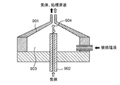
- a liquid processing apparatus in which a gas introduced from the outside is interposed between both electrodes (see Patent Document 1).
- a gas 904 for example, oxygen
- a pulse voltage is applied between the electrode 902 and the electrode 902.
- plasma is generated in the gas 904, and the decomposition treatment of the liquid to be processed 903 progresses at the contact surface between the plasma and the liquid to be processed 903.
- the applied voltage can be reduced as compared with the case where no gas is interposed, and the liquid can be processed by generating plasma efficiently.
- one end along the central axis is closed and the cross-sectional shape orthogonal to the central axis is circular, and the circular cross-sectional shape is formed on the one end side of the central axis.
- a cylindrical treatment tank having a liquid introduction port for turning the liquid around the central axis by introducing the liquid from the tangential direction of the liquid and generating a gas phase in the swirling flow of the liquid, and the treatment tank A rod-shaped first electrode disposed on the one end side of the central axis, a second electrode disposed on the other end side of the central axis of the processing tank, and between the first electrode and the second electrode A power source for applying a voltage to the first electrode, and an electrode rotating device for rotating the first electrode around a central axis of the first electrode.
- the tip end of the first electrode is averagely worn around the central axis by rotating the first electrode around the central axis of the first electrode by the electrode rotating device.
- the plasma can be stabilized, the plasma can be generated efficiently, the liquid can be processed quickly, the plasma can be generated stably for a long time, and the equipment can be operated for a long time.
- the liquid is vaporized in a swirling flow, and plasma is generated by applying a pulse voltage to the generated gas phase. Since it is not necessary to vaporize the liquid by applying a voltage, plasma can be generated with a small amount of power, and the liquid can be processed efficiently and quickly.
- FIG. 1 is a side cross-sectional view illustrating a configuration of a liquid processing apparatus according to Embodiment 1 of the present disclosure.
- FIG. 2 is a side sectional view of the apparatus main body.
- FIG. 3 is a cross-sectional view taken along line 3-3 in FIG.
- FIG. 4 is a side cross-sectional view showing a state where a swirling flow is generated inside the processing tank and no voltage is applied.
- FIG. 5A is a side cross-sectional view showing a state in which a swirling flow is generated inside the processing tank and a voltage is applied.
- FIG. 5B is a partially enlarged view of a state in which plasma is generated in the gas phase of FIG. 5A.
- FIG. 6 is a diagram illustrating how the wear of the first electrode progresses.
- FIG. 7 is a diagram illustrating an effect of preventing the first electrode from being biased and worn by the rotation mechanism.
- FIG. 8 is a diagram illustrating a difference in wear shape of the first electrode due to a difference in rotation angle and rotation interval of the rotation mechanism.
- FIG. 9 is a diagram showing a processing tank in which cylinders having different radii are combined.
- FIG. 10 is a diagram showing a conical treatment tank.
- FIG. 11 is a side sectional view showing a modification of the apparatus main body.
- FIG. 12A is a current waveform diagram when the plasma measured by the ammeter emits light.
- FIG. 12B is a side cross-sectional view in which a copper material is disposed in a part of the storage tank in a modification of the apparatus main body.
- FIG. 13 is a cross-sectional view of a conventional liquid processing apparatus.
- FIG. 14 is a cross-sectional view of a conventional liquid processing apparatus including a gas introduction device.
- a rod-shaped electrode is used as one electrode.
- the rod-shaped electrode is slightly inclined with respect to the discharge direction or attached with a slight eccentricity, so that when the plasma is generated between the electrodes for a long time, the tip of the rod-shaped electrode is biased. It will wear out. If the bias of the tip due to wear becomes large, plasma cannot be stably generated in the end, and thus there is a problem that the equipment cannot be operated for a long time.
- the present disclosure aims to provide a liquid processing apparatus capable of generating plasma efficiently and processing liquid quickly and stably generating plasma for a long time. .
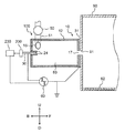
- FIG. 1 is a side cross-sectional view illustrating a configuration of a liquid processing apparatus 100 according to Embodiment 1 of the present disclosure.
- the arrow F indicates the forward direction of the liquid processing apparatus 100
- the arrow B indicates the backward direction.
- Arrow U indicates the upward direction
- arrow D indicates the downward direction.
- the arrow R indicates the right direction when viewed from the rear direction
- the arrow L indicates the left direction when viewed from the rear direction.
- the liquid processing apparatus 100 processes a liquid by discharging in the liquid.
- a liquid L1 in which a pollutant is dissolved is processed as an example of a liquid to be processed will be described.
- the processing liquid processed by the liquid processing apparatus 100 is stored.
- the liquid processing apparatus 100 functions as at least an example of a processing tank 12 having an introduction unit 15 that functions as an example of a liquid introduction port, a first electrode 30, a second electrode 31, a power source 60, and an electrode rotation device. And a rotation mechanism 200. More specifically, the liquid processing apparatus 100 includes an apparatus main body 10, a liquid supply unit 50, and a power supply 60.
- the apparatus main body 10 includes a processing tank 12, an introduction unit 15, a discharge unit 17, a first electrode 30, and a second electrode 31.
- the processing tank 12 is a cylindrical tank that is processing the liquid (for example, water) L1 introduced into the inside.
- the front sectional shape of the treatment tank 12 is circular (see FIG. 3).
- the introduction part 15 is disposed on one end side of the central axis X ⁇ b> 1 of the processing tank 12 that is closed, and the liquid L ⁇ b> 1 is supplied to the processing tank 12, for example, a tangential direction with a circular cross-sectional shape orthogonal to the central axis X ⁇ b> 1 of the processing tank 12. Introduce from.
- the introduction unit 15 communicates with the liquid supply unit 50 via the pipe 51.
- the discharge part 17 is arrange
- the discharge unit 17 is disposed on the other end side of the central axis X ⁇ b> 1 of the processing tank 12 and is connected to the intake port 91 of the storage tank 90.
- the processing liquid L2 discharged from the discharge unit 17 is stored in the storage tank 90.
- the first electrode 30 is a rod-shaped electrode in which at least an inner end portion is disposed inside one end of the treatment tank 12. As an example, the first electrode 30 is disposed so as to protrude from the center of the inner wall of one end of the processing tank 12 into the processing tank 12 along the longitudinal direction, for example, along the central axis X1.
- the material of the first electrode 30 is, for example, tungsten.
- the second electrode 31 is disposed outside the wall at the other end of the treatment tank 12 and is disposed in the vicinity of the discharge unit 17.
- the first electrode 30 is connected to a power source 60, and the second electrode 31 is grounded.
- a high voltage pulse voltage is applied to the first electrode 30 and the second electrode 31 by the power supply 60.
- Liquid supply part 50 is a pump which supplies liquid (for example, water) L1 in processing tank 12 as an example.
- the liquid supply unit 50 is connected to the pipe 51.
- One end of the pipe 51 is connected to an introduction portion 15 as an inner opening disposed in the vicinity of the inner wall of one end of the treatment tank 12, and the other end of the pipe 51 is a liquid supply source (for example, a water tank 80) (not shown) or It connects so that the stored water containing the processing liquid of the storage tank 90 can be circulated (refer the piping 81 for circulation of the dashed-dotted line of FIG. 1).
- the power source 60 applies a high voltage pulse voltage between the first electrode 30 and the second electrode 31.
- the power supply 60 can apply a so-called bipolar pulse voltage that alternately applies a positive pulse voltage and a negative pulse voltage.
- the rotation mechanism 200 is attached to the first electrode 30 and can rotate the first electrode 30 around the central axis 30c of the first electrode 30 (see FIG. 7) with respect to the processing bath 12.
- the rotation mechanism 200 includes a motor that can hold the first electrode 30 and can control the rotation angle. If necessary, for example, under the control of the control device 230, the first electrode 30 can be rotated by the rotation mechanism 200 by a predetermined angle at a predetermined time or a predetermined time interval after the power is turned on.
- the rotation mechanism 200 is driven and controlled by the control device 230, and under the control of the control device 230, the first electrode 30 is moved by the rotation mechanism 200 at a predetermined angle or a predetermined time from the voltage application by the power supply 60. It is possible to rotate.
- the storage tank 90 shears a treatment liquid discharged from the liquid processing apparatus 100, that is, a reforming component such as OH radicals, generates microbubbles or nanobubbles containing the reforming component, and generates a treatment liquid (for example, water).
- a reforming component such as OH radicals
- the storage tank 90 has a cross-sectional area larger than the opening cross-sectional area of the discharge part 17 of the treatment tank 12 inside, and stores the reforming components discharged from the discharge part 17 into the storage tank 90.
- Microbubbles containing the modified component, or microbubbles and nanobubbles are generated in the storage tank 90 and are diffused into water to generate a treatment liquid. Therefore, the storage tank 90 functions as a microbubble generation tank.
- As the storage tank 90 at least an inner diameter or one side that is twice or more the inner diameter dimension of the opening of the discharge portion 17 of the processing tank 12 can be secured, and a processing liquid that can surely sterilize can be generated in the storage tank 90. .
- FIG. 2 is a side sectional view of the apparatus main body 10.
- the treatment tank 12 has a first inner wall 21, a second inner wall 22, and a third inner wall 23.
- the material of the treatment tank 12 may be an insulator or a conductor. In the case of a conductor, it is necessary to interpose an insulator between the first electrode 30 and the second electrode 31.
- the first inner wall 21 is a cylindrical wall portion.
- the second inner wall 22 is provided at the left end portion of the first inner wall 21 in FIG.
- the third inner wall 23 is provided at the right end of the first inner wall 21 in FIG.
- the second inner wall 22 and the third inner wall 23 are substantially circular in a side view.
- the first inner wall 21, the second inner wall 22, and the third inner wall 23 constitute a substantially cylindrical accommodation space 83 inside the processing tank 12.
- the central axis of the first inner wall 21, that is, the virtual central axis of the substantially cylindrical accommodation space 83 configured inside the processing tank 12 is defined as a central axis X ⁇ b> 1.
- the second inner wall 22 is provided with a cylindrical electrode support cylinder 24 projecting into the accommodation space 83 at the center.
- the electrode support cylinder 24 is cylindrical and extends rightward.
- the electrode support cylinder 24 is arranged so that its central axis coincides with the central axis X1.
- the first electrode 30 is supported inside the electrode support cylinder 24 via an insulator 53.
- the first electrode 30 has a rod shape, and the insulator 53 is disposed around the first electrode 30. For this reason, the first electrode 30 is disposed such that the longitudinal axis thereof coincides with the central axis X1.
- the inner end surface of the right end portion 301 of the first electrode 30 protrudes into the accommodation space 83 from the inner end surface of the insulator 53, and the inner end surface 241 of the electrode support tube 24 extends from the inner end surface of the right end portion 301 of the first electrode 30. It is comprised so that it may protrude inside.
- the rotation mechanism 200 is attached to the first electrode 30 outside the processing tank 12, and the first electrode 30 is disposed at a predetermined time or a predetermined time interval with respect to the processing tank 12 around the central axis 30 c of the first electrode 30. Can be rotated by a predetermined angle.
- the central axis 30c of the first electrode 30 may be the same as or different from the central axis X1.
- the introduction part 15 penetrates the apparatus main body 10, and one open end 151 is formed on the first inner wall 21.
- the introduction portion 15 is disposed at a position adjacent to the second inner wall 22 in a side view.
- FIG. 3 is a cross-sectional view taken along line 3-3 in FIG.
- the introduction part 15 is disposed on the wall surface of the first inner wall 21.
- the discharge part 17 penetrates the central part of the third inner wall 23.
- the discharge portion 17 is formed so that its central axis coincides with the central axis X1.
- the second electrode 31 is a plate-like metal member, and an opening 311 is formed at the center.
- the opening 311 is circular, and is formed so that its central axis coincides with the central axis X1.
- FIG. 4 is a side cross-sectional view showing a state in which a swirling flow F1 is generated inside the processing tank 12 and no pulse voltage is applied.
- the pressure in the vicinity of the central axis X1 is reduced to the saturated water vapor pressure or less, and a part of the liquid L1 is vaporized to generate the gas phase G in the vicinity of the central axis X1.
- the gas phase G is generated near the turning center, specifically, from the right end 301 of the first electrode 30 to the vicinity of the opening 311 of the second electrode 31 along the central axis X1.
- the gas phase G is swirled in the same direction as the swirling flow F1 by the swirling flow F1 in contact therewith.
- the gas phase G receives the resistance of the liquid in the storage tank 90 in the vicinity of the discharge unit 17, so that it is sheared into microbubbles or microbubbles and nanobubbles and diffused into the liquid in the storage tank 90.
- FIG. 5A is a side sectional view showing a state in which a swirling flow F1 is generated inside the processing tank 12 and a pulse voltage is applied.
- FIG. 5B is an enlarged view showing a state where the plasma P is generated in the gas phase G.
- the power source 60 and the first electrode 30 A high voltage pulse voltage is applied between the two electrodes 31.
- the first electrode 30 and the second electrode 31 generate plasma P in the gas phase G (see FIG. 5B), and generate radicals (OH radicals or the like) or ions. .
- the radicals or ions are dissolved from the gas phase G to the swirl flow F1 side to decompose the pollutant dissolved in the solution.
- the plasma P in the gas phase G in the vicinity of the discharge unit 17 generates a large amount of bubbles BA containing OH radicals and the like due to the resistance of the liquid in the storage tank 90.
- the treatment liquid L ⁇ b> 2 that is treated with OH radicals generated by the plasma P and contains bubbles BA containing OH radicals and the like is discharged from the discharge unit 17 toward the storage tank 90.
- the plasma P can be generated efficiently and the liquid L1 can be processed quickly.
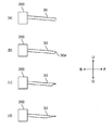
- FIG. 6 is a diagram illustrating how the wear of the first electrode 30 progresses.
- FIG. 6A shows an initial stage before plasma is generated. From this state, when the plasma L is generated and the liquid L1 is processed, the first electrode 30 is worn unevenly as shown in FIG. 6B, and the tip 30a becomes sharp. If the plasma P continues to be generated as it is, the bias becomes larger as shown in FIG. 6C, and finally the first electrode 30 is significantly biased as shown in FIG. 6D. As a result of wear, the gas phase G is also decentered and plasma generation becomes unstable.
- the first electrode 30 can be rotated by a predetermined angle around the central axis 30c of the first electrode 30 by a predetermined angle by the rotation mechanism 200. It is valid.
- FIG. 7 is a diagram illustrating an effect of preventing the first electrode 30 from being unevenly worn by rotating the first electrode 30 by the rotation mechanism 200.
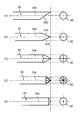
- FIG. 8 is a diagram illustrating a difference in the wear shape of the first electrode 30 due to a difference in rotation angle and rotation interval of the rotation mechanism 200.
- the total time during which the plasma P is generated is the same, and the rotation operation is performed at regular intervals.
- FIG. 8A shows a case where the first electrode 30 is not rotated
- FIG. 8B shows a case where 180 ° rotation is performed once
- FIG. 8C shows 90 ° rotation.
- 8 (d) shows the case where the 45 degree rotation is performed 7 times. In other words, FIG. 8 (e) always generates the plasma P while continuously rotating. Shows the case.
- FIG. 8 shows a case where the first electrode 30 is not rotated
- FIG. 8B shows a case where 180 ° rotation is performed once
- FIG. 8C shows 90 ° rotation.
- 8 (d) shows the case where the 45 degree rotation is performed 7 times.
- FIG. 8 (e) always generates the plasma P while continuously rotating. Shows the case.
- FIG. 8 shows
- FIG. 8 (a) only one side of the tip 30a of the rod electrode that is the first electrode 30 has been worn, but in FIG. 8 (b), both sides of the rod electrode are worn and the tip is It has a wedge shape.
- FIG. 8C in which the 90 ° rotation is performed three times, the four surfaces are worn and the sharpness of the tip is reduced.
- FIG. 8D the rotation angle is 45 degrees, and the sharpness of the tip is further reduced.
- FIG. 8E shows a case where the tip is always rotated (for example, during the plasma generation period), and the tip is sharpest and the tip shape is conical.
- the tip portion 30a of the first electrode 30 is averaged around the central axis 30c.
- the plasma P is stabilized, the plasma P is generated efficiently, the liquid L1 can be processed quickly, and the plasma P can be generated stably for a long time. It can be operated. That is, the phenomenon in which the first electrode 30 is slightly worn from the central axis X1 or is eccentrically attached and caused by the generation of plasma over a long period of time causes the first electrode 30 to be centered on the first electrode 30. It can be suppressed by rotating around the axis 30c, and the plasma P can be generated stably for a long time.
- the liquid L1 is vaporized in the swirling flow F1, and a pulse voltage is applied to the generated gas phase G to generate the plasma P. Therefore, the plasma P is generated efficiently.
- the liquid L1 can be processed quickly.
- the treatment tank 12 has a simple cylindrical shape.
- one end portion of the central axis X1 is a cylindrical treatment tank having a closed cross-section
- the shape is various. It is possible to take.
- the same effect can be obtained even in a processing tank 121 in which cylinders having different radii are combined.
- the radius of the cross-sectional area on the liquid introduction part side in the processing tank 121 is configured to be larger than the radius of the cross-sectional area on the liquid discharge part side.
- the same effect is acquired even if it is the cone-shaped process tank 122 shown in FIG.
- the swirling flow F1 from sliding in the forward direction F, as shown in FIG.
- the first electrode 30 was only rotated by the rotation mechanism 200.
- an electrode moving device 210, an ammeter 220, and a control device 230 are provided. Further, the distance between the first electrode 30 and the second electrode 31 may be adjustable.
- the ammeter 220 is connected between the first electrode 30 and the second electrode 31.
- the electrode moving device 210 changes the distance between the first electrode 30 and the second electrode 31 based on the current value measured by the ammeter 220. More specifically, the electrode moving device 210 includes, for example, a motor 211, a ball screw 212 that is coupled to the motor 211 and is driven to rotate forward and backward, and is screwed to the ball screw 212 and holds the first electrode 30. And a movable body 213 capable of moving back and forth in the axial direction of the first electrode 30. Therefore, when the control device 230 drives and controls the motor 211 based on the current value measured by the ammeter 220, the ball screw 212 rotates forward and backward, and the movable body 213 moves back and forth, so that the first electrode 30 can be taken in and out of the treatment tank 12.
- the control device 230 determines that the current waveform output from the ammeter 220 has changed from the initial state, this state means that the first electrode 30 is worn. For this reason, the control device 230 gives a control command to the electrode moving device 210, and the electrode moving device 210 inserts the first electrode 30 into the treatment tank 12, so that the first electrode 30 and the second electrode 31 are inserted. To control the distance.
- the insertion amount of the first electrode 30 is determined by previously obtaining the relationship between the state of change of the current waveform output from the ammeter 220 from the initial state and the wear state of the first electrode 30.
- the movement distance of the first electrode 30 to be inserted into the treatment tank 12 is also determined in advance corresponding to the state.
- the electrode moving device 210 can be driven and controlled so that the first electrode 30 can be inserted into the processing tank 12 by the moving distance of the first electrode 30.
- the distance between the first electrode 30 and the second electrode 31 can be maintained constant without directly measuring the distance between the first electrode 30 and the second electrode 31. It is possible to stabilize the plasma generation.
- control device 230 sets a determination threshold value as a current value output from the ammeter 220 that is equal to or less than the peak current value when the plasma emits light and equal to or more than the peak current value when the plasma does not emit light. By setting in this way, if the control device 230 determines that the current value output from the ammeter 220 is within the determination threshold, it means that the plasma is emitted. It can be easily determined by the control device 230. Further, the control device 230 can determine that the rate exceeding the determination threshold per unit time is the plasma generation rate.
- the control device 230 determines that the ratio exceeding the determination threshold per unit time is equal to or less than the desired ratio, the control device 230 drives the electrode moving device 210 to connect the first electrode 30 to the second electrode 31.
- the distance between the first electrode 30 and the second electrode 31 can be controlled to be constant.
- a desired plasma generation rate can be achieved by a simple method without directly measuring the distance between the first electrode 30 and the second electrode 31, and the plasma generation can be stabilized.
- the control device 230 can determine that the wear state shown in FIG.
- the control device 230 gives a control command to the electrode moving device 210 and sets the distance between the first electrode 30 and the second electrode 31. Control.
- the peak current value when plasma is emitted can be set to a state after the electrode distance in FIG. 12A (c) is controlled to be constant.
- the control for making the electrode distance constant by the control device 230 is stopped.
- a plate member 92 containing copper or iron that can cause a Fenton reaction with hydrogen peroxide water, which is one of the reforming components, to exhibit a high sterilization effect is stored in the storage tank 90.
- the plate member 92 may be disposed in the storage tank 90 as a separate member from the storage tank 90. In short, when the plate member 92 comes into contact with the reforming liquid in the storage tank 90, a high sterilizing effect can be exhibited by causing a Fenton reaction with hydrogen peroxide solution which is one of the reforming components.
- the configuration of the liquid processing apparatus 100 described in the first embodiment is an example, and various changes can be made.
- the internal structure of the processing tank 12 or the position of the first electrode 30 or the second electrode 31 is not limited to the structure of the first embodiment.
- the first electrode 30 is arranged on the closed end side of the cylindrical treatment tank 12 and the second electrode 31 is arranged in the vicinity of the discharge unit 17, but they are arranged opposite to each other. Even if it is, the same effect is acquired.
- Embodiment 1 of this indication was explained, Embodiment 1 mentioned above is only an illustration for carrying out this indication. Therefore, the present disclosure is not limited to the above-described first embodiment, and can be implemented by appropriately modifying the above-described first embodiment without departing from the spirit of the present disclosure.
- the liquid processing apparatus can maintain the distance between the two electrodes constant by rotating the electrode, the liquid can be generated efficiently and the liquid can be processed quickly. It can be generated stably for a long time. Therefore, the liquid processing apparatus according to the aspect of the present disclosure generates plasma in the liquid, thereby generating a decomposition and sterilization action caused by direct contact of the pollutant or bacteria contained in the liquid with the plasma, and plasma discharge.
- the liquid can be treated by causing simultaneous decomposition and sterilization by ultraviolet rays or radicals. For this reason, this processing liquid can be used for sterilization, deodorization, various environmental improvements, and the like.
- SYMBOLS 100 Liquid processing apparatus 10 Apparatus main body 12 Processing tank 121 Processing tank 122 Processing tank 15 Introduction part (liquid inlet) 17 discharge part 21 1st inner wall 22 2nd inner wall 23 3rd inner wall 24 Electrode support cylinder 30 1st electrode 30a Tip part 30b Lower side of tip part 30c Center axis (center axis of 1st electrode) 30d Reverse side of tip 31 Second electrode 50 Liquid supply part 51 Pipe 53 Insulator 60 Power supply 80 Water tank 81 Dotted line (circulation pipe) 83 Storage space 90 Storage tank 151 Open end 200 Rotating mechanism (electrode rotating device) DESCRIPTION OF SYMBOLS 210 Electrode moving apparatus 211 Motor 212 Ball screw 213 Movable body 220 Ammeter 230 Controller 241 Inner end surface 301 Right end 311 Opening 801 First electrode 802 Second electrode 803 Liquid 804 Pulse power source 805 Plasma 901 Anode electrode 902 Cathode electrode 903 Treatment liquid 904 Gas BA
Landscapes
- Chemical & Material Sciences (AREA)
- Organic Chemistry (AREA)
- Life Sciences & Earth Sciences (AREA)
- Hydrology & Water Resources (AREA)
- Engineering & Computer Science (AREA)
- Environmental & Geological Engineering (AREA)
- Water Supply & Treatment (AREA)
- Electrochemistry (AREA)
- General Chemical & Material Sciences (AREA)
- Chemical Kinetics & Catalysis (AREA)
- Health & Medical Sciences (AREA)
- Toxicology (AREA)
- Water Treatment By Electricity Or Magnetism (AREA)
- Plasma Technology (AREA)
Priority Applications (3)
| Application Number | Priority Date | Filing Date | Title |
|---|---|---|---|
| EP18742390.0A EP3604235A1 (de) | 2017-03-21 | 2018-01-29 | Flüssigkeitsbehandlungsvorrichtung |
| US16/082,208 US10723637B2 (en) | 2017-03-21 | 2018-01-29 | Liquid treatment apparatus |
| CN201880001226.XA CN108966648B (zh) | 2017-03-21 | 2018-01-29 | 液体处理装置 |
Applications Claiming Priority (2)
| Application Number | Priority Date | Filing Date | Title |
|---|---|---|---|
| JP2017-054438 | 2017-03-21 | ||
| JP2017054438A JP6664104B2 (ja) | 2017-03-21 | 2017-03-21 | 液体処理装置 |
Publications (1)
| Publication Number | Publication Date |
|---|---|
| WO2018173485A1 true WO2018173485A1 (ja) | 2018-09-27 |
Family
ID=63586102
Family Applications (1)
| Application Number | Title | Priority Date | Filing Date |
|---|---|---|---|
| PCT/JP2018/002741 Ceased WO2018173485A1 (ja) | 2017-03-21 | 2018-01-29 | 液体処理装置 |
Country Status (5)
| Country | Link |
|---|---|
| US (1) | US10723637B2 (de) |
| EP (1) | EP3604235A1 (de) |
| JP (1) | JP6664104B2 (de) |
| CN (1) | CN108966648B (de) |
| WO (1) | WO2018173485A1 (de) |
Cited By (1)
| Publication number | Priority date | Publication date | Assignee | Title |
|---|---|---|---|---|
| JP2018187601A (ja) * | 2017-05-11 | 2018-11-29 | パナソニックIpマネジメント株式会社 | 洗濯機すすぎ水浄化装置及び洗濯装置 |
Families Citing this family (6)
| Publication number | Priority date | Publication date | Assignee | Title |
|---|---|---|---|---|
| CN109589850B (zh) * | 2018-12-12 | 2024-07-16 | 江苏大学 | 一种高压静电辐射式微气泡发生装置 |
| JP7203324B2 (ja) * | 2019-05-07 | 2023-01-13 | パナソニックIpマネジメント株式会社 | 液体処理方法及び液体処理装置 |
| KR102404528B1 (ko) | 2019-09-02 | 2022-06-02 | 세메스 주식회사 | 노즐, 이를 포함하는 기판 처리 장치 및 기판 처리 방법 |
| KR102584515B1 (ko) * | 2020-07-06 | 2023-10-05 | 세메스 주식회사 | 노즐, 이를 포함하는 기판 처리 장치 및 기판 처리 방법 |
| CN112616234B (zh) * | 2020-12-30 | 2021-09-17 | 西安交通大学 | 一种利用直流源产生水中放电等离子体的装置及方法 |
| WO2022270534A1 (ja) * | 2021-06-23 | 2022-12-29 | 株式会社ナノプラネット研究所 | 旋回式微細気泡発生装置 |
Citations (10)
| Publication number | Priority date | Publication date | Assignee | Title |
|---|---|---|---|---|
| JP2000093967A (ja) | 1998-09-25 | 2000-04-04 | Masayuki Sato | 液体処理方法及び液体処理装置 |
| JP2002126741A (ja) * | 2000-10-23 | 2002-05-08 | Teruo Kojima | 電気分解装置 |
| JP2002159973A (ja) * | 2000-09-12 | 2002-06-04 | Kobe Steel Ltd | 液体処理方法およびその装置 |
| JP2006130410A (ja) * | 2004-11-05 | 2006-05-25 | Kobe Steel Ltd | 液体処理方法およびその装置 |
| JP2007069108A (ja) * | 2005-09-06 | 2007-03-22 | Ebara Corp | 放電処理システム |
| JP2013119043A (ja) * | 2011-12-06 | 2013-06-17 | Panasonic Corp | マイクロバブル発生デバイスとこれを用いた水処理装置 |
| US8734654B2 (en) * | 2001-07-16 | 2014-05-27 | Foret Plasma Labs, Llc | Method for treating a substance with wave energy from an electrical arc and a second source |
| US20150232353A1 (en) * | 2013-05-01 | 2015-08-20 | Nch Corporation | System and Method for Treating Water Systems with High Voltage Discharge and Ozone |
| JP2016033881A (ja) * | 2014-07-31 | 2016-03-10 | 株式会社融合技術開発センター | 液中ストリーマ放電の電極送り装置 |
| JP2016083658A (ja) * | 2014-10-24 | 2016-05-19 | パナソニックIpマネジメント株式会社 | プラズマ生成装置 |
Family Cites Families (15)
| Publication number | Priority date | Publication date | Assignee | Title |
|---|---|---|---|---|
| GB1437796A (en) * | 1973-07-09 | 1976-06-03 | Electricity Council | Production of ultra-violet radiation |
| US5844196A (en) | 1997-09-15 | 1998-12-01 | The Esab Group, Inc. | System and method for detecting nozzle and electrode wear |
| CN1136153C (zh) * | 1997-10-23 | 2004-01-28 | 星崎电机株式会社 | 电解水生成装置 |
| US7422695B2 (en) * | 2003-09-05 | 2008-09-09 | Foret Plasma Labs, Llc | Treatment of fluids with wave energy from a carbon arc |
| US10188119B2 (en) * | 2001-07-16 | 2019-01-29 | Foret Plasma Labs, Llc | Method for treating a substance with wave energy from plasma and an electrical arc |
| US20070267289A1 (en) | 2006-04-06 | 2007-11-22 | Harry Jabs | Hydrogen production using plasma- based reformation |
| FR2922406A1 (fr) * | 2007-10-12 | 2009-04-17 | Commissariat Energie Atomique | Dispositif d'injection de charge liquide a melanger/convertir au sein d'un dard plasma ou d'un flux gazeux |
| JP2010022991A (ja) | 2008-07-24 | 2010-02-04 | Yaskawa Electric Corp | 液体処理装置および液体処理方法 |
| GB2465173B (en) * | 2008-11-06 | 2011-06-29 | Nviro Cleantech Ltd | Fluid decontamination apparatus and method |
| US9023214B2 (en) | 2010-02-10 | 2015-05-05 | Aic, Llc | Method and apparatus for applying plasma particles to a liquid and use for disinfecting water |
| JP5099612B2 (ja) | 2011-04-26 | 2012-12-19 | 独立行政法人国立高等専門学校機構 | 液体処理装置 |
| CA2887851C (en) * | 2012-10-01 | 2017-11-28 | Foret Plasma Labs, Llc | Plasma arc torch having multiple operation modes |
| JP2014113517A (ja) | 2012-12-06 | 2014-06-26 | Samsung R&D Institute Japan Co Ltd | 水質制御装置及び水質制御方法 |
| JP5821020B2 (ja) * | 2013-04-18 | 2015-11-24 | パナソニックIpマネジメント株式会社 | 液体処理装置及び液体処理方法 |
| EP3063094A4 (de) * | 2013-11-01 | 2017-04-26 | Magnegas Corporation | Vorrichtung für den durchfluss von lichtbögen |
-
2017
- 2017-03-21 JP JP2017054438A patent/JP6664104B2/ja active Active
-
2018
- 2018-01-29 CN CN201880001226.XA patent/CN108966648B/zh active Active
- 2018-01-29 US US16/082,208 patent/US10723637B2/en active Active
- 2018-01-29 WO PCT/JP2018/002741 patent/WO2018173485A1/ja not_active Ceased
- 2018-01-29 EP EP18742390.0A patent/EP3604235A1/de not_active Withdrawn
Patent Citations (10)
| Publication number | Priority date | Publication date | Assignee | Title |
|---|---|---|---|---|
| JP2000093967A (ja) | 1998-09-25 | 2000-04-04 | Masayuki Sato | 液体処理方法及び液体処理装置 |
| JP2002159973A (ja) * | 2000-09-12 | 2002-06-04 | Kobe Steel Ltd | 液体処理方法およびその装置 |
| JP2002126741A (ja) * | 2000-10-23 | 2002-05-08 | Teruo Kojima | 電気分解装置 |
| US8734654B2 (en) * | 2001-07-16 | 2014-05-27 | Foret Plasma Labs, Llc | Method for treating a substance with wave energy from an electrical arc and a second source |
| JP2006130410A (ja) * | 2004-11-05 | 2006-05-25 | Kobe Steel Ltd | 液体処理方法およびその装置 |
| JP2007069108A (ja) * | 2005-09-06 | 2007-03-22 | Ebara Corp | 放電処理システム |
| JP2013119043A (ja) * | 2011-12-06 | 2013-06-17 | Panasonic Corp | マイクロバブル発生デバイスとこれを用いた水処理装置 |
| US20150232353A1 (en) * | 2013-05-01 | 2015-08-20 | Nch Corporation | System and Method for Treating Water Systems with High Voltage Discharge and Ozone |
| JP2016033881A (ja) * | 2014-07-31 | 2016-03-10 | 株式会社融合技術開発センター | 液中ストリーマ放電の電極送り装置 |
| JP2016083658A (ja) * | 2014-10-24 | 2016-05-19 | パナソニックIpマネジメント株式会社 | プラズマ生成装置 |
Non-Patent Citations (1)
| Title |
|---|
| See also references of EP3604235A4 |
Cited By (1)
| Publication number | Priority date | Publication date | Assignee | Title |
|---|---|---|---|---|
| JP2018187601A (ja) * | 2017-05-11 | 2018-11-29 | パナソニックIpマネジメント株式会社 | 洗濯機すすぎ水浄化装置及び洗濯装置 |
Also Published As
| Publication number | Publication date |
|---|---|
| JP6664104B2 (ja) | 2020-03-13 |
| EP3604235A4 (de) | 2020-02-05 |
| CN108966648B (zh) | 2022-03-01 |
| JP2018153779A (ja) | 2018-10-04 |
| US10723637B2 (en) | 2020-07-28 |
| CN108966648A (zh) | 2018-12-07 |
| EP3604235A1 (de) | 2020-02-05 |
| US20190256385A1 (en) | 2019-08-22 |
Similar Documents
| Publication | Publication Date | Title |
|---|---|---|
| WO2018173485A1 (ja) | 液体処理装置 | |
| JP6861378B2 (ja) | 改質液生成装置 | |
| US10610821B2 (en) | Deodorizing apparatus and deodorizing method | |
| JP6678338B2 (ja) | 液体処理装置 | |
| EP3647276B1 (de) | Flüssigkeitsbehandlungsvorrichtung | |
| JP2018202281A (ja) | 浴槽水処理装置及び浴槽装置 | |
| US10561760B2 (en) | Space modulation apparatus | |
| WO2017217170A1 (ja) | 改質液生成装置および改質液生成方法 | |
| JP6817594B2 (ja) | 液体処理装置 | |
| JP6799824B2 (ja) | 液体処理装置 | |
| CN108862494B (zh) | 洗涤机清洗水净化装置以及洗涤装置 | |
| JP7190696B2 (ja) | 液体処理方法及び液体処理装置 | |
| JP2018202282A (ja) | 貯留タンク水処理装置及び貯留式給湯装置 | |
| JP2018204842A (ja) | 加湿器 | |
| JP6817595B2 (ja) | 液体処理装置 | |
| JP7203324B2 (ja) | 液体処理方法及び液体処理装置 | |
| CN108975446B (zh) | 液体处理装置 | |
| JP2018196852A (ja) | 液体処理装置 | |
| JP2019198812A (ja) | 液体処理装置 | |
| HK1259797A1 (en) | Liquid treatment device | |
| JP2019198817A (ja) | 液体処理装置 |
Legal Events
| Date | Code | Title | Description |
|---|---|---|---|
| WWE | Wipo information: entry into national phase |
Ref document number: 2018742390 Country of ref document: EP |
|
| ENP | Entry into the national phase |
Ref document number: 2018742390 Country of ref document: EP Effective date: 20180724 |
|
| 121 | Ep: the epo has been informed by wipo that ep was designated in this application |
Ref document number: 18742390 Country of ref document: EP Kind code of ref document: A1 |
|
| NENP | Non-entry into the national phase |
Ref country code: DE |
|
| WWW | Wipo information: withdrawn in national office |
Ref document number: 2018742390 Country of ref document: EP |