WO2018182004A1 - 外部ヘッダー型複極式エレメント、外部ヘッダー型複極式電解槽、及び水素製造方法 - Google Patents
外部ヘッダー型複極式エレメント、外部ヘッダー型複極式電解槽、及び水素製造方法 Download PDFInfo
- Publication number
- WO2018182004A1 WO2018182004A1 PCT/JP2018/013948 JP2018013948W WO2018182004A1 WO 2018182004 A1 WO2018182004 A1 WO 2018182004A1 JP 2018013948 W JP2018013948 W JP 2018013948W WO 2018182004 A1 WO2018182004 A1 WO 2018182004A1
- Authority
- WO
- WIPO (PCT)
- Prior art keywords
- discharge port
- cathode
- anode
- bipolar
- vertical direction
- Prior art date
- Legal status (The legal status is an assumption and is not a legal conclusion. Google has not performed a legal analysis and makes no representation as to the accuracy of the status listed.)
- Ceased
Links
Images


Classifications
-
- C—CHEMISTRY; METALLURGY
- C25—ELECTROLYTIC OR ELECTROPHORETIC PROCESSES; APPARATUS THEREFOR
- C25B—ELECTROLYTIC OR ELECTROPHORETIC PROCESSES FOR THE PRODUCTION OF COMPOUNDS OR NON-METALS; APPARATUS THEREFOR
- C25B1/00—Electrolytic production of inorganic compounds or non-metals
- C25B1/01—Products
- C25B1/02—Hydrogen or oxygen
- C25B1/04—Hydrogen or oxygen by electrolysis of water
-
- C—CHEMISTRY; METALLURGY
- C25—ELECTROLYTIC OR ELECTROPHORETIC PROCESSES; APPARATUS THEREFOR
- C25B—ELECTROLYTIC OR ELECTROPHORETIC PROCESSES FOR THE PRODUCTION OF COMPOUNDS OR NON-METALS; APPARATUS THEREFOR
- C25B15/00—Operating or servicing cells
- C25B15/08—Supplying or removing reactants or electrolytes; Regeneration of electrolytes
- C25B15/083—Separating products
-
- C—CHEMISTRY; METALLURGY
- C25—ELECTROLYTIC OR ELECTROPHORETIC PROCESSES; APPARATUS THEREFOR
- C25B—ELECTROLYTIC OR ELECTROPHORETIC PROCESSES FOR THE PRODUCTION OF COMPOUNDS OR NON-METALS; APPARATUS THEREFOR
- C25B9/00—Cells or assemblies of cells; Constructional parts of cells; Assemblies of constructional parts, e.g. electrode-diaphragm assemblies; Process-related cell features
- C25B9/17—Cells comprising dimensionally-stable non-movable electrodes; Assemblies of constructional parts thereof
- C25B9/19—Cells comprising dimensionally-stable non-movable electrodes; Assemblies of constructional parts thereof with diaphragms
- C25B9/23—Cells comprising dimensionally-stable non-movable electrodes; Assemblies of constructional parts thereof with diaphragms comprising ion-exchange membranes in or on which electrode material is embedded
-
- C—CHEMISTRY; METALLURGY
- C25—ELECTROLYTIC OR ELECTROPHORETIC PROCESSES; APPARATUS THEREFOR
- C25B—ELECTROLYTIC OR ELECTROPHORETIC PROCESSES FOR THE PRODUCTION OF COMPOUNDS OR NON-METALS; APPARATUS THEREFOR
- C25B9/00—Cells or assemblies of cells; Constructional parts of cells; Assemblies of constructional parts, e.g. electrode-diaphragm assemblies; Process-related cell features
- C25B9/70—Assemblies comprising two or more cells
- C25B9/73—Assemblies comprising two or more cells of the filter-press type
- C25B9/77—Assemblies comprising two or more cells of the filter-press type having diaphragms
-
- Y—GENERAL TAGGING OF NEW TECHNOLOGICAL DEVELOPMENTS; GENERAL TAGGING OF CROSS-SECTIONAL TECHNOLOGIES SPANNING OVER SEVERAL SECTIONS OF THE IPC; TECHNICAL SUBJECTS COVERED BY FORMER USPC CROSS-REFERENCE ART COLLECTIONS [XRACs] AND DIGESTS
- Y02—TECHNOLOGIES OR APPLICATIONS FOR MITIGATION OR ADAPTATION AGAINST CLIMATE CHANGE
- Y02E—REDUCTION OF GREENHOUSE GAS [GHG] EMISSIONS, RELATED TO ENERGY GENERATION, TRANSMISSION OR DISTRIBUTION
- Y02E60/00—Enabling technologies; Technologies with a potential or indirect contribution to GHG emissions mitigation
- Y02E60/30—Hydrogen technology
- Y02E60/36—Hydrogen production from non-carbon containing sources, e.g. by water electrolysis
Definitions
- the present invention relates to an external header type bipolar element, an external header type bipolar electrolytic cell, and a hydrogen production method.
- renewable energy has the characteristic that its output varies greatly because it depends on climatic conditions. For this reason, it is not always possible to transport the power obtained by power generation using renewable energy to the general power system, and there are concerns about social impacts such as imbalance in power supply and demand and instability of the power system. Yes.
- Hydrogen is widely used industrially in scenes such as petroleum refining, chemical synthesis, and metal refining. In recent years, hydrogen can be used in hydrogen stations for fuel cell vehicles (FCV), smart communities, hydrogen power plants, etc. Sex is also spreading. For this reason, there is high expectation for the development of a technology for obtaining particularly high-purity hydrogen from renewable energy.
- FCV fuel cell vehicles
- Sex is also spreading. For this reason, there is high expectation for the development of a technology for obtaining particularly high-purity hydrogen from renewable energy.
- Water electrolysis methods include solid polymer water electrolysis, high temperature steam electrolysis, alkaline water electrolysis and the like.
- alkaline water electrolysis is one of the most promising because it has been industrialized for several decades or more, it can be implemented on a large scale, and it is cheaper than other water electrolysis devices. Has been.
- an object of the present invention is to provide an external header type bipolar element for alkaline water electrolysis that can simultaneously achieve gas-liquid separation properties and reduce the thickness of the entire electrolytic cell.
- An electrode including an anode and a cathode, a partition wall that separates the cathode and the anode, and a discharge port that discharges an electrolytic solution containing a gas generated in the electrode,
- An external header type bipolar element having a plurality of the discharge ports in a region sandwiched between the anode or the cathode and the partition.
- An electrode including an anode and a cathode, a partition wall that separates the cathode and the anode, and a discharge port that discharges an electrolytic solution containing a gas generated in the electrode,
- An external header type bipolar element for alkaline water electrolysis comprising a plurality of the discharge ports in a region sandwiched between the anode or the cathode and the partition.
- a plurality of the discharge ports are provided at different positions in the vertical direction,
- the discharge port at the highest position in the vertical direction is a discharge port that discharges more gas than the amount of gas discharged from the discharge port at the lowest position in the vertical direction.
- the plurality of discharge ports are provided at different positions in the vertical direction, In the discharge port at the highest position in the vertical direction, the inclination of the discharge port is 0 ° or more and 90 ° or less in the vertical direction with respect to the horizontal direction, and in the discharge port at the lowest position in the vertical direction, with respect to the horizontal direction.
- the bipolar element according to any one of [1] to [6], which is at least ⁇ 90 ° and not more than ⁇ 10 ° in the vertical direction.
- the discharge port and the electrolyte collecting pipe are connected through a hose, In the discharge port at the highest position in the vertical direction, the inclination of the hose at the discharge port is not less than 0 ° and less than 90 ° in the vertical direction with respect to the horizontal direction, and in the discharge port at the lowest position in the vertical direction, it is horizontal.
- the bipolar electrolytic cell according to [11] which is in the vertical direction with respect to the direction and at least ⁇ 90 ° and ⁇ 10 ° or less.
- the discharge port and the electrolyte collecting pipe are connected through a hose, The bipolar electrolytic cell according to any one of [11] to [14], wherein the hose includes a mechanism in which a gas layer is formed in the hose after the flow of the electrolytic solution is stopped.
- the discharge port and the electrolyte collecting pipe are connected through a hose, The bipolar electrolytic cell according to any one of [11] to [15], wherein the hose has an electrical resistivity of 1 M ⁇ ⁇ cm or more.
- the discharge port and the electrolyte collecting pipe are connected through a hose, The bipolar electrolytic cell according to any one of [11] to [16], wherein the hose is a hose that allows the inside of the hose to be visually recognized from the outside.
- the electrolytic cell has at least a bipolar element,
- the bipolar element includes an electrode including an anode and a cathode, a partition that separates the cathode and the anode, and a discharge port that discharges an electrolytic solution containing a gas generated at the electrode.
- the outer header type bipolar element In an area sandwiched between the cathode and the partition wall, the outer header type bipolar element having a plurality of the discharge ports, A method for producing hydrogen.
- an external header type bipolar element for alkaline water electrolysis that can simultaneously achieve gas-liquid separation and reducing the thickness of the entire electrolytic cell.
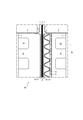
- FIG. 6 is a diagram showing a part of a cross section when cut by a plane along line AA in FIG. 5. It is a figure which shows an example of the connection of a conduit
- the present embodiment a mode for carrying out the present invention (hereinafter referred to as “the present embodiment”) will be described in detail.
- this invention is not limited to the following embodiment, It can implement by changing variously within the range of the summary.
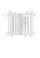
- FIG. 1 the side view about the whole of an example of the external header type
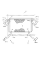
- FIG. 3 is a perspective view of a part of an example of an external header type bipolar electrolytic cell for alkaline water electrolysis according to this embodiment, a bipolar element, a header (hose), and a conduit.
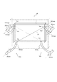
- FIG. 4 the perspective view about the flow of the electrolyte solution in a part of an example of the external header type
- a bipolar electrolytic cell 50 for alkaline water electrolysis includes an anode 2a, a cathode 2c, a partition wall 1 that separates the anode 2a and the cathode 2c, and an outer frame that borders the partition wall 1.
- 3 may be a bipolar electrolytic cell 50 in which a plurality of bipolar elements 60 provided with 3 are overlapped with the diaphragm 4 interposed therebetween.
- Bipolar type is one of the methods of connecting a large number of bipolar elements to a power source.
- a plurality of bipolar elements 60 one side of which is an anode 2a and one side of which is a cathode 2c, are arranged in the same direction and connected in series. In this method, only both ends are connected to the power source.
- the bipolar electrolytic cell 50 has a feature that the current of the power source can be reduced, and can produce a large amount of gas, a predetermined substance, etc. in a short time by electrolysis. As long as the output of the power supply equipment is the same, the constant current and high voltage are cheaper and more compact, so the bipolar type is preferable to the single pole type industrially.
- a bipolar element 60 used in a bipolar electrolytic cell 50 for alkaline water electrolysis includes a partition wall 1 that separates an anode 2 a and a cathode 2 c, and an outer frame that borders the partition wall 1. 3 is provided. More specifically, the partition wall 1 has conductivity, and the outer frame 3 is provided so as to surround the partition wall 1 along the outer edge of the partition wall 1.
- the bipolar element 60 may be used so that a given direction D1 along the partition wall 1 is normally a vertical direction, specifically, as shown in FIGS.
- a given direction D1 along the partition wall 1 is normally a vertical direction, specifically, as shown in FIGS.
- the shape of the partition 1 in plan view is a rectangle, it is used so that a given direction D1 along the partition 1 is the same as the direction of one of the two sets of opposing sides. Good.
- the external header type bipolar element 60 for alkaline water electrolysis of this embodiment (sometimes simply referred to as “bipolar element” in the present specification) includes an electrode 2 including an anode 2a and a cathode 2c, A partition wall 1 that separates the cathode 2c and the anode 2a, and a discharge port 5o (electrolyte outlet) that discharges an electrolyte containing gas generated in the electrode 2, the anode or the cathode and the partition A plurality of the discharge ports are provided in a region sandwiched between.
- the region includes a region 60a sandwiched between the anode and the partition wall (sometimes referred to as “region A” in this specification) and a region 60b sandwiched between the cathode and the partition wall (in this specification). (Referred to as “region B” in FIG. 6).
- the plurality of discharge ports provided in each region may be provided at the same position in the vertical direction. However, it may be provided at different positions in the vertical direction, but at least one gas is generated from the viewpoint that the gas generated in the electrode and the electrolytic solution are easily separated at the discharge port, and the electrolytic solution circulates more efficiently. It is preferable that the discharge port is provided at a position higher in the vertical direction than the other discharge ports, and it is more preferable that all the discharge ports are provided at different positions in the vertical direction. In the region A and the region B, the positions where the plurality of discharge ports are provided may be the same or different in the vertical direction.
- the discharge ports provided at different positions in the vertical direction are vertical from the viewpoint of further improving gas-liquid separation at the discharge ports.
- the lower end in the vertical direction of the discharge port at the highest position in the direction is vertically above the upper end in the vertical direction of the discharge port at the lowest position in the vertical direction, and the lower end in the vertical direction of the discharge port at the highest position in the vertical direction. It is more preferable that the distance between the discharge port at the lowest position in the vertical direction and the upper end in the vertical direction is 10 mm or more.
- the number of discharge ports provided in each region is two or more, depending on the discharge amount of the electrolytic solution. 3 or more (for example, 3).
- the number of discharge ports is most preferably two from the viewpoint of ease of manufacture.
- the number of discharge ports may be different or the same in the region A and the region B. From the viewpoint of ease of manufacturing a bipolar element, the region A and the region Both B are preferably provided with the same number of two or more outlets, more preferably two outlets.
- the gas generated at the electrode is preferably discharged from the discharge port at the highest position in the vertical direction.
- the gas is preferably discharged from a discharge port located at a high position in the vertical direction.
- the gas generated at the electrode is discharged only from the discharge port at the highest position in the vertical direction, and only the electrolytic solution is discharged from the discharge port at the lowest position in the vertical direction.
- the cross-sectional area of the discharge port is such that the gas-liquid separation between the gas and the electrolyte is further improved at the discharge port, and the circulating electrolyte From the viewpoint that the temperature of the diaphragm is not easily increased even in a long-term continuous operation, it is preferably 1.25 ⁇ 10 ⁇ 5 m 2 or more, more preferably 2.83 ⁇ 10 ⁇ . 5 m 2 or more.
- the cross-sectional area of the discharge port is preferably 7.85 ⁇ 10 ⁇ 5 m 2 or less, more preferably 5.03 ⁇ 10 ⁇ 5 m 2 or less.
- the plurality of ejection openings in each region may have the same or different cross-sectional areas. Especially, it is preferable that the cross-sectional area of all the discharge outlets is the same from a viewpoint with easy manufacture. Moreover, it is preferable that at least one discharge port satisfies the above, and it is more preferable that all the discharge ports satisfy the above.
- the shape of the discharge port is not particularly limited, and examples thereof include a substantially circular shape and a substantially polygonal shape.
- the inner diameter of the discharge port is preferably 4 mm or more, more preferably 6 mm or more.
- the inner diameter of the discharge port is preferably 16 mm or less, more preferably 10 mm or less, and still more preferably 8 mm or less.
- the shape and / or inner diameter of the discharge port may be the same or different in all the discharge ports.
- the thickness of the bipolar element is preferably 50 mm or less, more preferably from the viewpoint of making the electrolytic cell more compact. Is less than 50 mm, more preferably 15 mm or more and 40 mm or less, and particularly preferably 20 mm or more and 35 mm or less.
- the thickness of the bipolar element can be adjusted by, for example, the cross-sectional area of the discharge port.
- the thickness of the bipolar element refers to the distance between the anode and the cathode provided across the partition wall (distance from the anode outer end to the cathode outer end).
- the gas-liquid separability at the discharge port and the thickness of the entire electrolytic cell of the bipolar element are further enhanced.
- the relationship D / T between the inner diameter D (mm) of the discharge port and the thickness T (mm) of the bipolar element is preferably 0.1 or more, more preferably 0.15 or more, more preferably 0.2 or more.
- the relationship D / T is preferably 0.9 or less, and more preferably 0.4 or less.
- the inner diameter of the discharge port refers to the longest distance among the two points inside the discharge port.
- the electrolyte inlet for introducing the electrolyte is one for each region.
- the electrolytic solution inlet it is preferable to provide one electrolytic solution inlet and provide a plurality of discharge ports (electrolytic solution outlets).
- one anode electrolyte inlet 5ai and a plurality of anode electrolyte outlets 5ao are provided, and in the region B, one cathode electrolyte inlet 5ci and a plurality of cathode electrolyte outlets 5co.
- the region A one anode electrolyte inlet 5ai and a plurality of anode electrolyte outlets 5ao are provided, and in the region B, one cathode electrolyte inlet 5ci and a plurality of cathode electrolyte outlets 5co.
- the inclination ⁇ 1 of the discharge port at the highest position in the vertical direction of the discharge port of the bipolar element is the gas-liquid at the discharge port. From the viewpoint of further improving the separability, it is preferably 0 ° or more and 90 ° or less in the vertical direction with respect to the horizontal direction, more preferably 10 ° or more and 90 ° or less, and further preferably 15 ° or more and 75 ° or less. .
- the inclination ⁇ 2 of the discharge port at the lowest position in the vertical direction is from the viewpoint of further improving the gas-liquid separation at the discharge port.
- the vertical direction is ⁇ 90 ° to ⁇ 10 °, more preferably ⁇ 75 ° to ⁇ 15 °, and ⁇ 90 ° to 0 °.
- the inclination of the discharge port is a line segment connecting the two outer ends of the discharge port in the vertical section (surface parallel to the partition wall) of the bipolar element, and forms the longest line segment. This is the angle between the straight line connecting the ends and the horizontal direction (FIG. 9).
- the vertical direction upward with respect to the horizontal direction is defined as a positive angle
- the vertical direction downward gravitity direction, direction toward the center of the earth
- the horizontal direction refers to the direction of a surface perpendicular to the vertical direction.
- the position of the discharge opening of the bipolar element is, for example, from the vertical upper end of the bipolar element to the vertical of the electrode or the partition wall. It is preferable to be provided between the center in the direction, more preferably between 30% of the vertical length of the electrode or the partition wall from the upper end in the vertical direction, and the vertical length of the electrode or the partition wall from the upper end in the vertical direction. More preferably, it is provided up to 15%.
- a discharge port is provided in surfaces (for example, a vertical direction upper end surface, a horizontal direction both end surface, etc.) other than the surface in which the electrode of a bipolar element is provided.
- the position where the discharge port is provided refers to the position of the center of the discharge port in the vertical direction.
- the position where the discharge port is provided may be different between the region A and the region B, or may be the same.
- the external header type bipolar electrolytic cell of this embodiment (sometimes referred to simply as “bipolar electrolytic cell” in the present specification) is the above-mentioned external header type bipolar electrode (preferably, alkaline water electrolysis).
- the bipolar electrolytic cell 50 is configured by stacking a necessary number of bipolar elements 60.
- the bipolar electrolytic cell 50 has a fast head 51g, an insulating plate 51i, and an anode terminal element 51a arranged in order from one end, and further, an anode side gasket portion 7, a diaphragm 4, and a cathode side gasket portion. 7.
- Bipolar elements 60 are arranged in this order.
- the bipolar element 60 is arranged so that the cathode 2c faces the anode terminal element 51a side.
- the anode gasket portion 7 to the bipolar element 60 are repeatedly arranged as many times as necessary for the design production amount. After the necessary number of anode-side gasket portions 7 to the bipolar element 60 are repeatedly arranged, the anode-side gasket portion 7, the diaphragm 4, and the cathode-side gasket portion 7 are arranged again, and finally, the cathode terminal element 51c and the insulation
- the plate 51i and the loose head 51g are arranged in this order.
- the bipolar electrolyzer 50 is formed into a single body by tightening the whole by a tightening mechanism such as a tie rod method 51r (see FIG. 1) or a hydraulic cylinder method.
- the arrangement constituting the bipolar electrolytic cell 50 can be arbitrarily selected from the anode 2a side or the cathode 2c side, and is not limited to the order described above.
- the bipolar element 60 is disposed between the anode terminal element 51a and the cathode terminal element 51c.
- the diaphragm 4 is disposed between the anode terminal element 51a and the bipolar element 60, between the adjacent bipolar elements 60, and between the bipolar element 60 and the cathode terminal element 51c. .
- an electrode chamber 5 through which an electrolytic solution passes is defined by the partition wall 1, the outer frame 3, and the diaphragm 4.
- a region A60a sandwiched between the anode and the partition wall is a region in the anode chamber
- a region B60b sandwiched between the cathode and the partition wall is a region in the cathode chamber.
- a plurality of the discharge ports are provided in each of the anode chamber and the cathode chamber.
- a portion between the partition walls 1 is referred to as an electrolysis cell 65 (FIG. 1).
- the electrolysis cell 65 includes a partition 1 of one element, an anode chamber 5a, an anode 2a, and a diaphragm 4, and a cathode 2c, a cathode chamber 5c, and a partition 1 of the other element.
- the electrode chamber 5 has an electrolyte inlet 5 i for introducing an electrolyte into the electrode chamber 5 and an electrolyte outlet 5 o for leading the electrolyte from the electrode chamber 5 at the boundary with the outer frame 3.
- the electrolyte outlet 5o corresponds to the discharge port.
- the anode chamber 5a has an anode electrolyte inlet 5ai that introduces an electrolyte into the anode chamber 5a, and an anode electrolyte outlet 5ao that leads out (discharges and discharges) the electrolyte discharged from the anode chamber 5a. 5 ago are provided.
- the cathode chamber 5c has a cathode electrolyte inlet 5ci for introducing an electrolyte into the cathode chamber 5c, and a cathode electrolyte outlet 5co, 5cgo for deriving an electrolyte discharged (discharged and discharged) from the cathode chamber 5c.
- a cathode electrolyte inlet 5ci for introducing an electrolyte into the cathode chamber 5c
- a cathode electrolyte outlet 5co, 5cgo for deriving an electrolyte discharged (discharged and discharged) from the cathode chamber 5c.
- the anode chamber 5a and the cathode chamber 5c may be provided with an internal distributor for uniformly distributing the electrolytic solution within the electrolytic cell 50 within the electrode surface.
- the electrode chamber 5 may include a baffle plate having a function of restricting the flow of the liquid inside the electrolytic cell 50.
- Karman vortices are used to make the concentration and temperature of the electrolyte in the electrolytic cell 50 uniform, and to promote the defoaming of gas adhering to the electrode 2 and the diaphragm 4. You may provide the protrusion for making.
- the bipolar electrolytic cell 50 in this embodiment includes a header 10 that communicates with the electrode chamber 5 outside the outer frame 3 (see FIGS. 3 to 5).
- a header 10 that is a pipe for distributing or collecting a gas or an electrolyte is attached to the bipolar element.
- the header 10 includes an inlet header for introducing an electrolytic solution from the distribution pipe into the electrode chamber 5 and an outlet header for discharging a gas and an electrolytic solution from the electrode chamber 5 to the liquid collecting tube.
- an anode inlet header 10 Oai that puts an electrolytic solution into the region A (a part of the anode chamber 5 a) and an electrolysis in the region B (a part of the cathode chamber 5 c).
- cathode outlet headers 10Oao, 10Oago for discharging the electrode liquid and gas from the region A on the upper side of the outer frame 3 at the edge of the partition wall 1.
- the cathode outlet headers 10Oco and 10Ocgo for discharging the electrolyte and gas from the region B are provided. Since the bipolar element of this embodiment has a plurality of discharge ports (electrolyte outlets), it is connected to a plurality of outlet headers. Further, in one example, in the region A (a part of the anode chamber 5a) and the region B (a part of the cathode chamber 5c), the inlet header and the outlet header occupy the central portion of each region (the central portion of the electrode chamber 5). It is provided so as to face each other.
- the bipolar electrolytic cell 50 of this example employs an external header 10O type bipolar element in which the bipolar electrolytic cell 50 and the header 10 are independent.
- FIG. 4 an example of the external header type
- the conduit 20 includes a liquid distribution pipe that communicates with the inlet header and a liquid collection pipe that communicates with the outlet header.
- the anode liquid distribution tube 20Oai communicating with the anode inlet header 10Oai and the cathode liquid distribution tube 20Oci communicating with the cathode inlet header 10Oci are provided below the outer frame 3, the anode liquid distribution tube 20Oai communicating with the anode inlet header 10Oai and the cathode liquid distribution tube 20Oci communicating with the cathode inlet header 10Oci are provided.
- anode collection tube 20 Oao communicating with the anode outlet headers 10 Oao and 10 Oago and a cathode collection tube 20 Oco communicating with the cathode exit headers 10 Oco and 10 Ocgo.
- the discharge port at the highest position in the vertical direction among the anode electrolyte solution outlets 5ao is the highest position in the vertical direction among 5ago and the cathode electrolyte solution outlet 5co.
- the discharge port may be 5 cgo.
- the outlet hoses (exit headers) 10Oao and 10Oco extending from the electrolyte outlets 5ao and 5co the outlet hoses (exit headers) extending from the discharge ports 5ago and 5cgo at the highest position in the vertical direction are 10Oago and 10Ocgo.
- the discharge ports 5 ago and 5 cgo at the highest position in the vertical direction are preferably discharge ports that discharge more gas than the amount of gas discharged from the discharge port at the lowest position in the vertical direction.
- the discharge ports 5ago and 5cgo at the highest position in the vertical direction are discharge ports that discharge an electrolyte less than the amount of the electrolyte discharged from the discharge port at the lowest position in the vertical direction.
- tube improves, and the gas-liquid separation efficiency in a gas-liquid separation tank can be improved.
- the amount of gas discharged from the discharge port at the highest position is 10 times or more than the amount of gas discharged from the discharge port at the lowest position.
- the amount of the electrolyte discharged from the discharge port at the highest position is 1/10 or less of the amount of the electrolyte discharged from the discharge port at the lowest position.
- the gas amount and the electrolyte amount refer to the total amount of gas flowing per unit time and the total amount of electrolyte. It is preferable that only gas is discharged from outlet hoses (outlet headers) 10Ogo and 10Ocgo extending from the discharge ports 5ago and 5cgo at the highest positions in the vertical direction.
- the inlet header and the outlet header are provided at separate positions from the viewpoint of water electrolysis efficiency.
- the electrodes are provided so as to face each other with the central portion of the electrode chamber 5 interposed therebetween.
- the anode liquid distribution pipe 20Oai, the cathode liquid distribution pipe 20Oci, the anode liquid collection pipe 20Oao, and the cathode liquid collection pipe 20Oco are provided one by one in each electrode chamber 5, but in this embodiment, It is not limited and may be shared by the plurality of electrode chambers 5.
- the rectangular partition wall 1 in plan view and the rectangular diaphragm 4 in plan view are arranged in parallel, and the rectangular parallelepiped outer frame provided on the edge of the partition wall 1 side. Since the inner surface of the electrode chamber 5 is perpendicular to the partition wall 1, the shape of the electrode chamber 5 is a rectangular parallelepiped.
- the shape of the electrode chamber 5 is not limited to the rectangular parallelepiped in the illustrated example, and the planar view shape of the partition wall 1 and the diaphragm 4, the inner surface of the outer frame 3 on the partition wall 1 side, and the partition wall 1.
- the shape may be appropriately changed depending on the angle formed, and any shape may be used as long as the effect of the present invention is obtained.
- the positional relationship between the electrode chamber 5 and the header 10 is not particularly limited. As shown in FIGS.
- the inlet header is located below or on the side of the electrode chamber 5 (downward in the drawing), and the outlet header. May be located above or to the side of the electrode chamber 5 (upper side in the drawing), and the liquid distribution pipe communicating with the inlet header is located below or to the side of the electrode chamber 5
- the liquid collection pipe communicating with the outlet header may be located above or laterally with respect to the electrode chamber 5 (upper side in the figure).
- the extending direction of the conduit 20 is not particularly limited, but the effects of the present invention can be achieved as in the example shown in FIGS.
- the liquid distribution pipe anode liquid distribution pipe 20Oai, cathode liquid distribution pipe 20Oci
- the liquid collection pipe anode liquid collection pipe 20Oao, cathode liquid collection pipe 20Oco
- the convection generated in the electrolytic chamber 5 due to the turbulence of the gas-liquid flow in the electrolytic chamber 5 is reduced, and the temperature of the local electrolytic solution is increased.
- a plurality of rectifying plates 6 (ribs) arranged in parallel to a given direction D1 along the partition wall 1 may be provided.
- the discharge ports and the electrolyte solution collecting pipe are connected by hoses (anode outlet headers 10Oao, 10Oago, cathode outlet headers 10Oco, 10Ocgo).
- hoses anode outlet headers 10Oao, 10Oago, cathode outlet headers 10Oco, 10Ocgo.
- the inclination ⁇ 3 of the hose at the discharge port at the highest position in the vertical direction is a viewpoint that further improves the gas-liquid separation at the discharge port.
- the hose at the discharge port at the lowest position in the vertical direction is ⁇ 90 ° or more and 0 ° or less in the vertical direction with respect to the horizontal direction from the viewpoint of further improving the gas-liquid separation at the discharge port. It may be more than ⁇ 90 ° and ⁇ 10 ° or less, more preferably ⁇ 75 ° or more and ⁇ 15 ° or less.
- the inclination of the hose refers to an angle formed by the direction of the hose and the horizontal direction at the connection point between the discharge port and the hose in the vertical section (surface parallel to the partition wall) of the bipolar element ( FIG. 9).
- a line segment connecting the center of the hose cross section perpendicular to the flow direction of the electrolyte of the hose for example, a line segment having a length of 1 mm from the connection point, a position 1 mm from the connection point and the connection point.
- An angle formed by a horizontal line connecting the hose cross-sectional center.
- the bipolar electrolytic cell has a relatively heavy electrolysis in order to improve the separation between the gas generated by electrolysis and the electrolytic solution.
- the electrolyte collecting pipe is provided vertically below the discharge port, and provided below the discharge port at the lowest position in the vertical direction. More preferably.
- the distance h between the vertical center of the discharge port at the lowest position in the vertical direction and the vertical center of the vertical cross section of the electrolytic solution collecting pipe is preferably 100 mm or more, more preferably It is 200 to 1400 mm, more preferably 600 to 1200 mm.
- the bipolar electrolytic cell is a relatively light gas in order to improve the separation between the gas generated by electrolysis and the electrolytic solution.
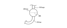
- the hose extending from the discharge port at the highest position in the vertical direction is connected to the electrolytic solution collecting pipe vertically above the vertical center of the vertical cross section of the electrolytic solution collecting pipe. It is preferable that a hose extending from the discharge port at the lowest position in the direction is connected to the electrolyte solution collecting pipe at a position vertically below the vertical center of the vertical cross section of the electrolyte solution collecting pipe (FIGS. 7 and 9). ).
- the hoses 10Oago and 10Ocgo extending from the discharge port on the upper side in the vertical direction are connected to the upper side in the vertical direction from the cross-sectional center 20h of the electrolyte solution collecting tubes 20Oao and 20co. It is preferable that the hoses 10Oao and 10Oco extending from the discharge port on the side are connected to the lower side in the vertical direction from the cross-sectional center 20h of the electrolyte solution collection tubes 20Oao and 20co (FIGS. 7 and 9).
- the bipolar electrolytic cell 50 for alkaline water electrolysis of this embodiment has a plurality of bipolar elements 60.
- the shape of the partition wall 1 in the present embodiment may be a plate shape having a predetermined thickness, but is not particularly limited.
- the partition wall 1 may be used so that a given direction D1 along the partition wall 1 is usually a vertical direction. Specifically, as shown in FIGS. May be used such that a given direction D1 along the partition wall 1 is in the same direction as the direction of one of the two sets of sides facing each other.
- the material of the partition wall 1 is preferably a conductive material from the viewpoint of realizing uniform power supply, and nickel, nickel alloy, mild steel, and nickel alloy are plated with nickel from the viewpoint of alkali resistance and heat resistance. Is preferred.
- the electrolysis voltage of alkaline water electrolysis is the overvoltage of the anode reaction (oxygen generation), the overvoltage of the cathode reaction (hydrogen generation), the anode 2a and the cathode 2c. It is divided into the voltage depending on the distance between the electrodes 2.
- the overvoltage refers to a voltage that needs to be applied excessively beyond the theoretical decomposition potential when a certain current flows, and the value depends on the current value. When the same current flows, the power consumption can be reduced by using the electrode 2 having a low overvoltage.
- the requirements for the electrode 2 include high conductivity, high oxygen generation capability (or hydrogen generation capability), and high wettability of the electrolyte on the electrode 2 surface. Can be mentioned.
- the electrode 2 in the present embodiment is preferably a porous body in order to increase the surface area used for electrolysis and to efficiently remove gas generated by electrolysis from the surface of the electrode 2.
- porous body examples include plain weave mesh, punching metal, expanded metal, metal foam and the like.
- the electrode 2 in the present embodiment may be the substrate itself or may have a catalyst layer with high reaction activity on the surface of the substrate, but preferably has a catalyst layer with high reaction activity on the surface of the substrate. .
- the material of the base material is not particularly limited, but mild steel, stainless steel, nickel, and nickel-based alloy are preferable because of resistance to the use environment.
- the catalyst layer of the anode 2a preferably has a high oxygen generation capacity, and nickel, cobalt, iron, platinum group elements, or the like can be used.
- the catalyst layer can be formed as a single metal, a compound such as an oxide, a complex oxide or alloy composed of a plurality of metal elements, or a mixture thereof.
- An organic substance such as a polymer may be contained in order to improve durability and adhesion to the substrate.
- the catalyst layer of the cathode 2c is preferably one having a high hydrogen generation capability, and nickel, cobalt, iron, a platinum group element, or the like can be used.
- the catalyst layer can be formed as a single metal, a compound such as an oxide, a complex oxide or alloy composed of a plurality of metal elements, or a mixture thereof.
- An organic substance such as a polymer material may be included in order to improve durability and adhesion to the substrate.
- a thermal spraying method such as a plating method or a plasma spraying method, a thermal decomposition method in which heat is applied after applying a precursor layer solution on the substrate, a catalyst substance is mixed with a binder component
- a method such as a method of fixing to a substrate and a vacuum film forming method such as a sputtering method.
- the shape of the outer frame 3 in the present embodiment is not particularly limited as long as the partition wall 1 can be bordered. .
- the shape of the outer frame 3 is not particularly limited and may be appropriately determined according to the shape of the partition wall 1 in plan view.
- the material of the outer frame 3 is preferably a conductive material, and nickel, nickel alloy, mild steel, and nickel alloy plated with nickel are preferable from the viewpoint of alkali resistance and heat resistance.
- an ion-permeable diaphragm 4 is used to isolate generated hydrogen gas and oxygen gas while conducting ions.
- an ion exchange membrane having ion exchange ability and a porous membrane capable of permeating an electrolytic solution can be used.
- the ion-permeable diaphragm 4 is preferably one having low gas permeability, high ionic conductivity, low electronic conductivity, and high strength.
- Porous membrane-- The porous membrane has a plurality of fine through-holes and a structure that allows the electrolyte solution to pass through the diaphragm 4. Control of the porous structure such as pore diameter, porosity, and hydrophilicity is very important because the electrolyte solution expresses ionic conduction by permeating into the porous membrane. On the other hand, it is required that not only the electrolyte solution but also the generated gas not pass through, that is, have a gas barrier property. From this point of view, control of the porous structure is important.
- the porous membrane has a plurality of fine through holes, and examples thereof include a polymer porous membrane, an inorganic porous membrane, a woven fabric, and a nonwoven fabric. These can be produced by a known technique.
- the thickness of the porous film is not particularly limited, but is preferably 200 ⁇ m or more and 700 ⁇ m or less. If the thickness of the porous film is 250 ⁇ m or more, further excellent gas barrier properties can be obtained, and the strength of the porous film against impact can be further improved. From this viewpoint, the lower limit of the thickness of the porous film is more preferably 300 ⁇ m or more, further preferably 350 ⁇ m or more, and still more preferably 400 ⁇ m or more. On the other hand, if the thickness of the porous membrane is 700 ⁇ m or less, the ion permeability is hardly hindered by the resistance of the electrolytic solution contained in the pores during operation, and more excellent ion permeability can be maintained.
- the upper limit of the thickness of the porous film is more preferably 600 ⁇ m or less, further preferably 550 ⁇ m or less, and even more preferably 500 ⁇ m or less.
- the polymer resin contains at least one selected from the group consisting of polysulfone, polyethersulfone and polyphenylsulfone, this effect is further improved.
- the ion exchange membrane there are a cation exchange membrane that selectively permeates cations and an anion exchange membrane that selectively permeates anions, and any of the exchange membranes can be used.
- the material for the ion exchange membrane is not particularly limited, and known materials can be used.
- a fluorine-containing resin or a modified resin of polystyrene / divinylbenzene copolymer can be suitably used.
- a fluorine-containing ion exchange membrane is preferable from the viewpoint of excellent heat resistance and chemical resistance.
- a spring which is an elastic body is disposed between the electrode 2 and the partition wall 1, and the electrode 2 is supported by this spring. It is preferable.
- a spring made of a conductive material may be attached to the partition wall 1 and the electrode 2 may be attached to this spring.
- a spring may be attached to the electrode rib 6 attached to the partition wall 1, and the electrode 2 may be attached to the spring.
- a conductive elastic body 2 e and a current collector are provided between the cathode 2 c or the anode 2 a and the partition 1. 2r is provided such that the conductive elastic body 2e is sandwiched between the cathode 2c or the anode 2a and the current collector 2r.
- the current collector 2r transmits electricity to the conductive elastic body 2e and the electrode 2 laminated thereon, supports the load received from them, and allows the gas generated from the electrode 2 to pass through the partition wall 1 without any trouble. is there. Therefore, the shape of the current collector 2r is preferably an expanded metal or a punched perforated plate.
- the aperture ratio of the current collector 2r is preferably within a range in which the hydrogen gas generated from the electrode 2 can be extracted to the partition wall 1 side without hindrance. However, if the aperture ratio is too large, the strength may decrease or the conductivity to the conductive elastic body 2e may decrease, and if it is too small, the gas escape may be deteriorated.
- Nickel, nickel alloy, stainless steel, mild steel, etc. can be used as the material of the current collector 2r from the viewpoint of conductivity and alkali resistance, but nickel or mild steel or stainless steel nickel alloy is plated from the corrosion resistance aspect. Is preferred.
- the current collector 2r is fixed to the rib 6 by means such as spot welding or laser welding.
- the conductive elastic body 2 e is between the current collector 2 r and the electrode 2 and is in contact with the current collector 2 r and the electrode 2, so that electricity is transmitted to the electrode 2 and does not hinder diffusion of gas generated from the electrode 2. It is an essential requirement. This is because by inhibiting the diffusion of gas, the electrical resistance increases, and the area of the electrode 2 used for electrolysis decreases, so that the electrolysis efficiency decreases. The most important role is to bring the diaphragm 4 and the electrode 2 into close contact with each other by applying an appropriate pressure to the electrode 2 so as not to damage the diaphragm 4.
- the conductive elastic body 2e a conventionally known material can be used.
- a cushion mat formed by corrugating a woven wire of nickel having a wire diameter of about 0.05 to 0.5 mm has a zero gap structure Z. It is preferable because it is easy to maintain.
- the material is not limited, but nickel, nickel alloy, stainless steel, or mild steel plated with nickel is preferable in terms of conductivity and alkali resistance.
- the conductive elastic body 2e having a thickness of usually about 1 mm to 20 mm can be used.
- the electrode 2 base material that can be used for the zero gap structure Z the electrode 2 having a small wire diameter and a small mesh is preferable because of its high flexibility.
- a base material generally known materials can be used.
- nickel, nickel alloy, stainless steel, mild steel, nickel alloy, stainless steel or mild steel plated with nickel can be used as the base material of the cathode 2c.
- These substrates preferably have a wire diameter of 0.05 to 0.5 mm and an opening of about 30 to 80 mesh.
- an electrode chamber 5 through which an electrolytic solution passes is defined by the partition wall 1, the outer frame 3, and the diaphragm 4.
- a rectifying plate 6 (anode rectifying plate 6a, cathode rectifying plate 6c) is attached to the partition wall 1, and the rectifying plate 6 (rib) is physically connected to the electrode 2. It is preferable that they are connected. According to such a configuration, the current plate 6 serves as a support for the electrode 2, and the zero gap structure Z is easily maintained.
- the electrode 2 may be provided on the current plate 6, and the current collector 2 r, the conductive elastic body 2 e, and the electrode 2 may be provided on the current plate 6 in this order.
- the bipolar electrolytic cell 50 for alkaline water electrolysis of the above-described example, a structure in which the rectifying plate 6—the current collector 2r—the conductive elastic body 2e—the electrode 2 are stacked in this order in the cathode chamber 5c is employed. In the chamber 5a, a structure in which the current plate 6 and the electrode 2 are stacked in this order is employed.
- the structure of “rectifying plate 6—current collector 2r—conductive elastic body 2e—electrode 2” is adopted in the cathode chamber 5c, and the anode chamber The structure of the “rectifying plate 6-electrode 2” is adopted in 5a.
- the present invention is not limited to this, and the anode chamber 5a also includes “rectifying plate 6—current collector 2r—conductive elastic body.
- a “2e-electrode 2” structure may be employed.
- the rectifying plate 6 (anode rectifying plate 6a, cathode rectifying plate 6c) preferably has not only a role of supporting the anode 2a or the cathode 2c but also a role of transmitting current from the partition wall 1 to the anode 2a or the cathode 2c.
- the bipolar electrolytic cell 50 for alkaline water electrolysis of the present embodiment it is preferable that at least a part of the rectifying plate 6 has conductivity, and it is more preferable that the entire rectifying plate 6 has conductivity. According to such a configuration, an increase in cell voltage due to electrode deflection can be suppressed.
- a conductive metal is generally used as a material for the current plate 6.
- mild steel plated with nickel, stainless steel, nickel or the like can be used.
- the interval between adjacent anode rectifying plates 6a or the interval between adjacent cathode rectifying plates 6c is determined in consideration of the electrolytic pressure, the pressure difference between the anode chamber 5a and the cathode chamber 5c, and the like.
- the length of the rectifying plate 6 (the anode rectifying plate 6a and the cathode rectifying plate 6c) may be appropriately determined according to the size of the partition wall 1.
- the height of the current plate 6 depends on the distance from the partition wall 1 to each flange, the thickness of the gasket 7, the thickness of the electrode 2 (anode 2a, cathode 2c), the distance between the anode 2a and the cathode 2c, etc. And may be determined as appropriate. Further, the thickness of the rectifying plate 6 may be 0.5 mm to 5 mm in consideration of cost, manufacturability, strength, and the like.
- the gasket 7 having the diaphragm 4 is sandwiched between the outer frames 3 that border the partition wall 1.
- the gasket 7 is used for sealing between the bipolar element 60 and the diaphragm 4 and between the bipolar element 60 against the electrolytic solution and the generated gas. Gas mixing between the bipolar chambers can be prevented.
- the material of the gasket 7 is not particularly limited, and a known rubber material or resin material having insulating properties can be selected.
- rubber materials and resin materials include natural rubber (NR), styrene butadiene rubber (SBR), chloroprene rubber (CR), butadiene rubber (BR), acrylonitrile-butadiene rubber (NBR), and silicone rubber (SR). ), Ethylene-propylene rubber (EPT), ethylene-propylene-diene rubber (EPDM), fluorine rubber (FR), isobutylene-isoprene rubber (IIR), urethane rubber (UR), chlorosulfonated polyethylene rubber (CSM), etc.
- NR natural rubber
- SBR styrene butadiene rubber
- CR chloroprene rubber
- BR butadiene rubber
- NBR acrylonitrile-butadiene rubber
- silicone rubber SR
- EPT Ethylene-propylene rubber
- EPDM ethylene-prop
- PTFE polytetrafluoroethylene
- PFA tetrafluoroethylene / perfluoroalkyl vinyl ether copolymer
- ETFE tetrafluoroethylene / ethylene copolymer
- ECTFE chlorotrifluoroethylene / ethylene copolymer
- a resin material polyphenylene sulfide (PPS)
- PPS polyphenylene sulfide
- EPDM ethylene-propylene-diene rubber
- FR fluororubber
- the size of the gasket 7 is not particularly limited, and may be designed according to the dimensions of the electrode chamber 5 and the membrane, but the width is preferably 10 mm to 40 mm.
- the thickness of the gasket 7 is not particularly limited, and is designed according to the material, elastic modulus, and cell area of the gasket 7.
- the preferred thickness range is 1.0 mm to 10 mm, more preferably 3.0 mm to 10 mm.
- the elastic modulus of the gasket 7 is not particularly limited, and is designed according to the material of the electrode 2 and the cell area.
- the range of the elastic modulus is more preferably a range of 0.20 MPa to 20 MPa in terms of tensile stress at 100% deformation, and a range of 1.0 MPa to 10 MPa is more preferable from the viewpoint of sealing characteristics and cell strength at the time of stacking.
- the tensile stress can be measured according to JIS K6251. For example, Autograph AG manufactured by Shimadzu Corporation may be used.
- the bipolar electrolytic cell 50 for alkaline water electrolysis has a cathode chamber 5 c and an anode chamber 5 a for each electrolytic cell 65.
- an electrolytic solution sufficiently containing raw materials consumed by electrolysis to the cathode chamber 5c and the anode chamber 5a of each electrolysis cell 65.
- the electrolytic cell 65 is connected to an electrolyte supply / discharge pipe called a header 10 common to the plurality of electrolytic cells 65.
- the anode distribution pipe is called an anode inlet header 10ai
- the cathode distribution pipe is called a cathode inlet header 10ci
- the anode collection pipe is called an anode outlet header 10ao
- the cathode collection pipe is called a cathode outlet header 10co.
- the electrolysis cell 65 is connected to each electrode liquid distribution pipe and each electrode liquid collection pipe through a hose or the like.
- the material of the header 10 is not particularly limited, but it is necessary to adopt a material that can sufficiently withstand the corrosiveness of the electrolyte used and the operating conditions such as pressure and temperature.
- the material of the header 10 may be iron, nickel, cobalt, PTFE, ETFE, PFA, polyvinyl chloride, polyethylene, or the like.
- the range of the electrode chamber 5 varies depending on the detailed structure of the outer frame 3 provided at the outer end of the partition wall 1, and the detailed structure of the outer frame 3 depends on the header 10 (electrolysis) attached to the outer frame 3. It may differ depending on the arrangement mode of the pipe for distributing or collecting the liquid.
- the header 10 of the bipolar electrolytic cell 50 an internal header type and an external header 10O type are typical.
- the external header 10O type refers to a type in which the bipolar electrolytic cell 50 and the header 10 (a pipe for distributing or collecting an electrolytic solution) are independent.
- the external header 10O type bipolar electrolytic cell 50 is independent in such a manner that the anode inlet header 10Oai and the cathode inlet header 10Oci run in parallel with the electrolytic cell 50 in a direction perpendicular to the current-carrying surface of the electrolytic cell 65.
- the anode inlet header 10Oai and the cathode inlet header 10Oci are connected to each electrolysis cell 65.
- Anode inlet header 10Oai, cathode inlet header 10Oci, anode outlet headers 10Oao, 10Oago, and cathode outlet headers 10Oco, 10Ocgo which are externally connected to the external header 10O type bipolar electrolytic cell 50, Called the external header 10O.
- a luminal member is installed in a through hole for the header 10 provided in a lower portion of the outer frame 3 at the edge of the partition wall 1, and the luminal member is , Connected to the anode inlet header 10Oai and the cathode inlet header 10Oci, and similarly to the through hole for the header 10 provided in the upper portion of the outer frame 3 at the edge of the partition wall 1, A tubular member (for example, a hose or a tube) is installed, and the tubular member is connected to the anode outlet header 10Oao and the cathode outlet header 10Oco.
- the internal header type and external header type bipolar electrolytic cell 50 may have a gas-liquid separation box that separates the gas generated by electrolysis from the electrolytic solution therein.
- the attachment position of the gas-liquid separation box is not particularly limited, but may be attached between the anode chamber 5a and the anode outlet header 10ao, or between the cathode chamber 5c and the cathode outlet header 10co.
- the surface of the gas-liquid separation box may be coated with a coating material that can sufficiently withstand the corrosiveness of the electrolyte and the operating conditions such as pressure and temperature.
- the material of the coating material may be an insulating material for the purpose of increasing the electrical resistance of the leakage current circuit inside the electrolytic cell.
- EPDM, PTFE, ETFE, PFA, polyvinyl chloride, polyethylene or the like may be adopted as the material of the coating material.
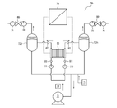
- the electrolytic apparatus 70 for alkaline water electrolysis of the present embodiment includes a bipolar electrolytic cell 50 for alkaline water electrolysis of the present embodiment, a liquid feed pump 71 for circulating the electrolytic solution, an electrolytic solution, hydrogen, and / or oxygen. And a water replenishment tank 72 for replenishing water consumed by electrolysis.
- the effect of the bipolar electrolytic cell for alkaline water electrolysis of this embodiment can be obtained. That is, according to the present embodiment, during operation with a variable power source such as renewable energy, it is possible to realize long-term storage and long-distance transportation of large power due to the function of the reverse electric absorber of the electrode 2, The electric control system can be stabilized by reducing the self-discharge generated when the power supply is stopped. According to the present embodiment, furthermore, it is possible to realize electric power storage with high efficiency, specifically, reduction of pump power and reduction of leakage current.
- a variable power source such as renewable energy
- the liquid feed pump 71 used in the present embodiment is not particularly limited and may be appropriately determined.
- the gas-liquid separation tank 72 used in the present embodiment includes a hydrogen separation tank 72h that separates the electrolyte and hydrogen gas, and an oxygen separation tank 72o that separates the electrolyte and oxygen gas.
- the hydrogen separation tank 72h is connected to the cathode chamber 5c, and the oxygen separation tank 72o is connected to the anode chamber 5a.
- the gas-liquid separation tank 72 of the alkaline water electrolysis system is provided with an oxygen separation tank 72o used for the anode chamber 5a and a hydrogen separation tank 72h used for the cathode chamber 5c.
- the gas-liquid separation tank 72 for the anode chamber 5a separates the oxygen gas and the electrolyte generated in the anode chamber 5a
- the gas-liquid separation tank 72 for the cathode chamber 5c includes the hydrogen gas and the electrolyte generated in the cathode chamber 5c. Isolate.
- the gas and electrolyte flowing into the gas-liquid separation tank 72 are divided into a gas phase in the upper layer of the tank and an electrolyte in the liquid phase in the lower layer of the tank.
- the degree of gas-liquid separation is determined by the bundle of electrolyte solution in the gas-liquid separation tank 72, the speed at which the generated gas bubbles float, and the residence time in the gas-liquid separation tank 72.
- the electrolytic solution after the gas is separated flows out from the outlet at the bottom of the tank and flows into the electrolytic cell 65 again to form a circulation path. Since oxygen and hydrogen gas discharged from the discharge port above the tank both contain alkali mist, excess mist such as mist separators and coolers are liquefied and separated into gas and liquid downstream of the discharge port. It is preferable to attach a device that can be returned to the tank 72.
- the gas-liquid separation tank 72 may be provided with a liquid level gauge in order to grasp the liquid level height of the electrolyte stored inside.
- the gas-liquid separation tank 72 preferably includes a pressure release valve. As a result, even if the pressure rises due to the gas generated by electrolysis, the pressure can be safely lowered when the design pressure is exceeded.
- the inlet to the gas-liquid separation tank 72 is preferably located above the electrolyte surface in order to improve gas-liquid separation, but is not limited to this.
- the electrolytic solution level in the gas-liquid separation tank 72 is preferably higher than the upper surface of the electrolytic cell, but is not limited thereto.
- a shutoff valve between the electrolysis cell 65 and the gas-liquid separation tank 72, it is not limited to this.
- an alkali-resistant metal such as nickel is used.
- a general-purpose metal such as iron is used as a tank housing material
- the surface in which the electrolyte solution inside the tank is coated with a fluorine resin may be used.
- the material of the separation tank 72 is not limited.
- the capacity of the gas-liquid separation tank 72 is preferably small in consideration of the installation volume, but if the volume is too small, the pressure difference between the cathode 2c and the anode 2a becomes large or the electrolytic current value fluctuates. Since the liquid level in the tank fluctuates, it is necessary to consider this fluctuation. Similarly, when the height of the tank is low, it is preferable to increase the tank height because it is easily affected by the above fluctuation.
- Water replenisher 73 It does not specifically limit as the water replenisher 73 used in this embodiment, You may determine suitably.
- water generally clean water may be used, but in consideration of long-term operation, it is preferable to use ion exchange water, RO water, ultrapure water, or the like.
- the electrolyzer 70 for alkaline water electrolysis includes a rectifier 74, an oxygen concentration meter 75, a hydrogen concentration meter 76, and a flow meter 77 in addition to the bipolar electrolytic cell 50, the gas-liquid separation tank 72, and the water replenisher 73. , A pressure gauge 78, a heat exchanger 79, a pressure control valve 80, thermometers 81 and 82, and the like.
- the electrolyzer 70 for alkaline water electrolysis of the present embodiment further includes a detector that detects the stop of power supply and a controller that automatically stops the liquid feed pump.
- a detector that detects the stop of power supply
- a controller that automatically stops the liquid feed pump.
- the alkaline water electrolysis method of the present embodiment can be carried out using the alkaline water electrolysis electrolytic apparatus 70 of the present embodiment.
- a gas such as hydrogen or oxygen can be produced.
- the method for producing hydrogen according to the present embodiment is a hydrogen production method in which water containing an alkali is electrolyzed in an electrolytic cell to produce hydrogen, wherein the electrolytic cell has at least a bipolar element, and the bipolar type
- the element includes an electrode including an anode and a cathode, a partition that separates the cathode and the anode, and a discharge port that discharges an electrolytic solution containing a gas generated at the electrode.
- the anode or the cathode and the element An external header type bipolar element having a plurality of the discharge ports in a region sandwiched between partition walls. Suitable conditions for the method are described below.
- the electrolytic solution used in the present embodiment may be an alkaline aqueous solution in which an alkali salt is dissolved, and examples thereof include an aqueous NaOH solution and an aqueous KOH solution.
- concentration of the alkali salt is preferably 20% by mass to 50% by mass, and more preferably 25% by mass to 40% by mass.
- a 25% by mass to 40% by mass KOH aqueous solution is particularly preferable from the viewpoint of ionic conductivity, kinematic viscosity, and freezing at low temperature.
- the temperature of the electrolytic solution in the electrolytic cell 65 is preferably 80 ° C. to 130 ° C. If it is set as the said temperature range, it can suppress effectively that the members of electrolysis apparatus 70, such as the gasket 7 and the diaphragm 4, by heat, maintain high electrolysis efficiency.
- the temperature of the electrolytic solution is more preferably 85 ° C. to 125 ° C., and particularly preferably 90 ° C. to 115 ° C.
- the current density applied to the electrolytic cell 65 is preferably 4kA / m 2 ⁇ 20kA / m 2, a 6kA / m 2 ⁇ 15kA / m 2 .
- the pressure in the electrolysis cell 65 is preferably 3 kPa to 1000 kPa, and more preferably 3 kPa to 300 kPa.
- the alkaline water electrolysis electrolytic device 70 having the configuration shown in FIG. 8 can be produced using the components of the alkaline water electrolysis electrolytic device 70 described above, but the present invention is not limited thereto. It is not something.
- the electrolytic solution in the outlet hose is stopped by stopping the liquid feed pump when the power supply to the bipolar electrolytic cell for alkaline water electrolysis is stopped. It is preferable to stop the flow.
- the electrolytic solution flows down to the outlet header due to its own weight, so that an insulating gas layer is formed in the outlet hose.
- the liquid resistance of the outlet hose increases infinitely, so that leakage current hardly flows through the outlet hose. As a result, the influence of self-discharge can be reduced.
- the bipolar electrolytic cell of the present embodiment preferably includes a mechanism for forming a gas layer in the hose after the flow of the electrolytic solution is stopped.
- the mechanism include a structure having a gas-liquid separation tank liquid level at a position lower than the discharge port, and a point where the hose between the discharge port and the electrolyte liquid collecting pipe changes from vertically upward to vertically downward.
- the electrical resistivity can be measured by an insulation resistance meter, and an existing M ⁇ tester can be used.
- the hose is preferably a hose that allows the inside of the hose to be visually recognized from the outside.
- Examples of the visible hose include a light-transmitting hose. Since the gas-liquid state in the hose can be confirmed, it is possible to confirm whether the operation state during electrolysis is in a stable state. For example, when the circulation amount of the electrolytic solution is too large, it can be confirmed that the gas-liquid separation property deteriorates and the electrolytic solution flows out to the gas hose side.
- the material of such a hose has alkali, high temperature, and pressure resistance.
- a fluorine type is preferable, and there is a hose made of PTFE or PFA.
- the light transmittance can be determined from the light transmittance measured in accordance with JIS K7361-1.
- the visible hose is preferably a hose having the light transmittance of 10% or more.
- the bipolar electrolytic cell As described above, the bipolar electrolytic cell, the electrolytic device, the alkaline water electrolysis method, and the hydrogen production method of the embodiment of the present invention have been illustrated and described with reference to the drawings. Water electrolysis method.
- the hydrogen production method is not limited to the above example, and the above embodiment can be modified as appropriate.
- outer frame- As the bipolar element, an element including a partition wall for partitioning the anode and the cathode and an outer frame 3 surrounding the partition wall was used.
- the materials for the members in contact with the electrolyte such as the partition walls and the frame of the bipolar element were all nickel.
- anode As the anode, a nickel expanded base material that had been blasted in advance was used, and a granulated product of nickel oxide was sprayed on both surfaces of the conductive base material by plasma spraying. This electrode was made into an anode whose dimensions were adjusted to 1155 mm in length and 2354 mm in width by cutting.
- a material in which platinum was supported on a plain woven mesh base material knitted with 40 mesh of fine nickel wires having a diameter of 0.15 mm was used.
- the size of the cathode in plan view was 1155 mm ⁇ 2354 mm.
- a bipolar element was stacked through a gasket holding a diaphragm, and a bipolar electrolytic cell was assembled to press and contact the cathode and anode samples from both sides of the diaphragm to form a zero gap structure. Only the anode sample was used on the anode side, and a cathode sample composed of a combination of “cathode—conductive elastic body—current collector” was used on the cathode side. The above-mentioned thing was used as an anode sample. As the current collector, a nickel expanded substrate that had been previously blasted was used. The thickness of the base material was 1 mm, and the aperture ratio was 54%.
- the conductive elastic body As the conductive elastic body, a woven fabric using four nickel wires having a wire diameter of 0.15 mm so as to have a wave height of 5 mm was used. The thickness was 5 mm, the repulsive force at the time of 50% compression deformation was 150 g / cm 2 , and the opening was about 5 mesh. The conductive elastic body was fixed on the current collector by spot welding. The above-mentioned thing was used as a cathode sample.
- Polysulfone 15 parts by mass Polyvinylpyrrolidone: 6 parts by mass N-methyl-2-pyrrolidone: 70 parts by mass Zirconium oxide: 45 parts by mass
- the above coating liquid was used as a base material for polyphenylene sulfide mesh (manufactured by KUBALA, film thickness)
- the coating was applied to both surfaces of 280 ⁇ m, openings 358 ⁇ m, and fiber diameter 150 ⁇ m.
- the substrate coated with the coating solution was exposed to steam, and then immersed in a coagulation bath to form a coating film on the substrate surface. Thereafter, the coating film was sufficiently washed with pure water to obtain a porous film.
- the diaphragm was adjusted to a length of 1172 mm ⁇ width of 2369 mm by cutting to obtain a diaphragm sample.
- Bipolar element- Four bipolar elements are used, and as shown in FIG. 1, a fast head, an insulating plate, and an anode terminal unit are arranged on one end side, and further, an anode side gasket portion, a diaphragm, a cathode side gasket portion, Four sets of bipolar elements arranged in this order are arranged. Furthermore, the anode side gasket part, the diaphragm, and the cathode side gasket part are arranged.
- the cathode terminal unit, the insulating plate, and the loose head were stacked by tightening them from both sides of the fast head and the loose head with a gasket seal surface pressure of 2450 kN / m 2 to assemble a bipolar electrolytic cell.
- the cathode chamber and the anode chamber had five pairs of series connection structures each having five chambers.
- the gasket is 4.0 mm thick and 18 mm wide and has an inside dimension of 1155 mm ⁇ 2354 mm.
- the gasket has an opening on the inside having the same dimensions as the electrode chamber in plan view, and is held by inserting a diaphragm. What has a slit structure was used.
- Example 1 Multipolar element- A bipolar element having a rib height of 7 mm for each of the anode chamber and the cathode chamber and a thickness of the bipolar element of 21 mm was used.
- conduit- An external header type bipolar element was adopted.
- a conduit 20 anode liquid distribution for distributing and collecting the electrolytic solution outside the casing of the electrolytic cell 50.
- hoses an anode inlet header 10Oai and a cathode inlet header 10Oci as an inlet header 10i for allowing the electrolyte to pass from the liquid distribution pipes 20i (inlet conduits) to the electrode chamber 5 are externally provided.
- the outlet header 10o anode outlet header 10Oao, 10Oago, cathode outlet header 10Oco, 10Ocgo) that allows the electrolytic solution and / or gas to pass from the electrode chamber 5 to the liquid collecting tube 20o (exit side conduit) was attached from the outside. .
- headers 10Oago and 10Ocgo connected to discharge ports at a high position in the vertical direction and headers 10Oao and 10Oco connected to discharge ports at a low position in the vertical direction were provided.
- the inlet headers (anode inlet header 10Oai, cathode inlet header 10Oci) are disposed outwardly from the lower end in the vertical direction of the bipolar element 60, and the outlet header (anode outlet header 10Oao, 10Oago).
- the cathode outlet headers 10Oco and 10cgo) are arranged so as to extend outward from the side of the partition wall 1 of the bipolar element 60. As shown in FIGS.
- any of the conduits 20 is a bipolar type.
- the element 60 was arranged so as to extend in a direction perpendicular to the partition wall 1. Further, the inclination ⁇ 2 of the electrolyte outlets (discharge outlets) 5co and 5ao positioned below is set at ⁇ 45 °, and the inclination ⁇ 4 of the electrolyte outlet headers 10Oao and 10Oco is connected to ⁇ 45 °.
- the inclinations ⁇ 1 of the electrolyte outlets (discharge ports) 5cgo and 5ago located vertically above are set at 45 °, and the inclinations ⁇ 3 of the electrolytic gas outlet headers 10Oago and 10Ocgo are connected to 45 °.
- the position of the discharge port located above the vertical direction is such that the vertical upper end of the discharge port is 28 mm from the vertical upper end of the bipolar element, and the vertical downward direction
- the position at which the discharge port of the discharge port is provided was set such that the upper end in the vertical direction of the discharge port was 135 mm from the upper end in the vertical direction of the bipolar element.
- an inlet side thermometer 81 for measuring the temperature of the inlet side electrolyte solution is attached to the electrolyte inlet side conduit 20i (anode distribution pipe 20Oai, cathode distribution pipe 20Oci), and the electrolyte outlet side pipe 20o (
- An outlet-side thermometer 82 for measuring the temperature of the outlet-side electrolyte was attached to the anode-side collector tube 20Oao and the cathode-side collector tube 20Oco) (FIG. 8).
- the electrolyte solution was allowed to flow from the cathode chamber 5c to the cathode chamber 5c via the cathode inlet header 10Oci and via the cathode outlet headers 10Oco and 10cgo.
- the electrolyte solution was flowed from the anode chamber 5a to the anode chamber 5a via the anode inlet header 10Oai and via the anode outlet headers 10Oao and 10Oago.
- the inlet hose is connected to one end of the lower side of the rectangular outer frame 3 in side view
- the outlet hose is connected to the other end side of the lower side of the rectangular outer frame 3 in side view.
- Each is connected to the upper side.
- the inlet hose and the outlet hose are provided so as to face each other across the central portion of the electrode chamber 5 in the rectangular electrode chamber 5 in a side view.
- the electrolyte flowed from below to above while inclining with respect to the vertical direction, and rose along the electrode surface (FIG. 4).
- the electrolyte flows into the anode chamber 5a and the cathode chamber 5c from the inlet hose of the anode chamber 5a and the cathode chamber 5c, and from the outlet hose of the anode chamber 5a and the cathode chamber 5c.
- the electrolytic solution and the generated gas flow out of the electrolytic cell 50.
- the hoses are all made of PFA and are translucent (white light transmittance is about 50%), and the gas-liquid state in the hose can be visually observed.
- the electrical resistivity of the hose is 1 M ⁇ ⁇ cm or more.
- the bipolar electrolytic cell of Example 1 was produced by the following procedure.
- a bipolar element was prepared by attaching a cathode to the cathode surface of a bipolar frame and an anode attached to the anode surface of the frame of the bipolar element. Moreover, what attached the cathode to the flame
- the area S1 of the electrodes (anode and cathode) attached to the bipolar element was adjusted to 2.7 m 2 .
- the discharge port inner diameter is 6 mm
- the discharge port cross-sectional area is 2.83 ⁇ 10 ⁇ 5 It was adjusted to m 2.
- the distance h between the vertical center of the discharge port on the lower side in the vertical direction and the vertical center of the vertical cross section of the electrolyte liquid collecting pipe was 600 mm.
- the thickness T of the bipolar element was adjusted to 21 mm.
- a single diaphragm was sandwiched between the anode terminal element and the cathode side of the bipolar element.
- Four bipolar elements are arranged in series so that one anode side and the other cathode side of the adjacent bipolar elements are opposed to each other, and three pieces are arranged between adjacent bipolar elements. Were sandwiched one by one. Further, one diaphragm was sandwiched between the anode side of the fourth bipolar element and the cathode terminal element.
- a bipolar electrolyzer of Example 1 was obtained by using a fast head, an insulating plate, and a loose head, and tightening them with a press.
- a 30% aqueous KOH solution was used as the electrolytic solution. Circulation of the anode chamber, oxygen separation tank (anode gas-liquid separation tank) and anode chamber was performed by a liquid feed pump, and circulation of the cathode chamber, hydrogen separation tank (cathode gas-liquid separation tank) and cathode chamber was performed. . The temperature of the electrolytic solution was adjusted to 80 ° C. with the temperature of the inlet side thermometer 81.
- a gas-liquid separation tank having a height of 1400 mm and a volume of 1 m 3 was prepared.
- the liquid volume in the gas-liquid separation tank was about 50% of the design volume.
- a current was passed from the rectifier to the bipolar electrolytic cell so that the area of each cathode and anode was 10 kA / m 2 .
- the area S1 of the electrode was 2.7 mm 2 , 27 kA was energized from the rectifier to the bipolar electrolytic cell.
- the pressure in the electrolytic cell was measured with a pressure gauge, and electrolysis was performed while adjusting the cathode side pressure to 50 kPa and the oxygen side pressure to 49 kPa.
- the pressure adjustment was performed by a pressure control valve installed downstream of the pressure gauge.
- Example 1 The alkaline water electrolysis in Example 1 was evaluated as follows.
- Example 2 The anode chamber and the cathode chamber were manufactured in the same manner as in Example 1 except that a bipolar element in which the rib height was 14 mm and the thickness of the bipolar element was 35 mm was used. The frequency was adjusted so that the in-cell linear velocity was 0.007 m / sec. Even at 10 kA / m 2 high density, both the anode and cathode have good gas-liquid separation. Gas is discharged from the discharge header provided on the upper side in the vertical direction, and electrolyte is discharged from the discharge header provided on the lower side in the vertical direction. It was done. The temperature of the outlet side electrolyte solution was 90 ° C., which was lower than the heat resistant temperature of the diaphragm.
- Example 3 It was produced in the same manner as in Example 1 except that the distance h between the vertical center of the discharge port on the lower side in the vertical direction and the vertical center of the vertical cross section of the electrolyte liquid collecting tube was set to 300 mm. The frequency was adjusted so that the in-cell linear velocity was 0.015 m / sec. Even at 10 kA / m 2 high electrical density, both the anode and cathode have good gas-liquid separation, and gas is discharged from the discharge header provided on the upper side in the vertical direction, and electrolyte is discharged from the discharge header provided on the lower side in the vertical direction. It was done. The temperature of the outlet side electrolyte solution was 90 ° C., which was lower than the heat resistant temperature of the diaphragm.
- Example 4 It was produced in the same manner as in Example 1 except that the distance h between the vertical center of the discharge port on the lower side in the vertical direction and the vertical center of the vertical cross section of the electrolyte liquid collecting tube was 1200 mm. The frequency was adjusted so that the in-cell linear velocity was 0.015 m / sec. Even at 10 kA / m 2 high electrical density, both the anode and cathode have good gas-liquid separation, and gas is discharged from the discharge header provided on the upper side in the vertical direction, and electrolyte is discharged from the discharge header provided on the lower side in the vertical direction. It was done. The temperature of the outlet side electrolyte solution was 90 ° C., which was lower than the heat resistant temperature of the diaphragm.
- Example 5 In the header (anode inlet header, anode outlet header, cathode inlet header, cathode outlet header) provided on the side of the outer frame, the discharge port inner diameter is 4 mm, and the discharge port cross-sectional area is 1.26 ⁇ 10 ⁇ 5 It was produced in the same manner as in Example 1 except that it was adjusted to m 2 . The frequency was adjusted so that the in-cell linear velocity was 0.015 m / sec. Even at 10 kA / m 2 high electrical density, both the anode and cathode have good gas-liquid separation, and gas is discharged from the discharge header provided on the upper side in the vertical direction, and electrolyte is discharged from the discharge header provided on the lower side in the vertical direction. It was done. The temperature of the outlet side electrolyte solution was 90 ° C., which was lower than the heat resistant temperature of the diaphragm.
- Example 6 It was produced in the same manner as in Example 1 except that the distance h between the vertical center of the discharge port on the lower side in the vertical direction and the vertical center of the vertical cross section of the electrolyte liquid collecting tube was set to 100 mm. The frequency was adjusted so that the in-cell linear velocity was 0.015 m / sec. Even at a high electrical density of 10 kA / m 2 , the gas-liquid separation was good for both the anode and the cathode. Gas was mixed from the discharge header provided on the upper side in the vertical direction and a very small amount of gas was mixed from the discharge header provided on the lower side in the vertical direction, but the electrolyte was mainly discharged. No pulsation was seen. The temperature of the outlet side electrolyte solution was 90 ° C., which was lower than the heat resistant temperature of the diaphragm.
- Example 7 The inclination ⁇ 2 of the electrolyte outlet outlets 5co, 5ao is connected at an angle of ⁇ 90 °, the inclination ⁇ 4 of the electrolyte outlet headers 10Oao, 10Oco is 0 °, and the inclination ⁇ 1 of the electrolyte outlet outlets 5cgo, 5ago is It was produced in the same manner as in Example 2 except that the inclination ⁇ 3 of the electrolytic gas outlet headers 10Oago and 10Ocgo was connected to an angle of 0 °. The frequency was adjusted so that the in-cell linear velocity was 0.007 m / sec. Compared with Example 2, the gas-liquid separation was slightly deteriorated, and the electrolyte flowed into the gas discharge port provided on the upper side, but there was no pulsation in the electrolyte flow.
- Comparative Example 1 It was produced in the same manner as in Example 1 except that the discharge port on the upper side in the vertical direction was not provided. The frequency was adjusted so that the in-cell linear velocity was 0.015 m / sec. The gas-liquid separation at the discharge port deteriorated, and pulsation due to the mixed phase flow of the electrolytic solution and electrolytic gas occurred in the outlet hose.
- Comparative Example 2 It was produced in the same manner as in Example 2 except that the upper discharge port was not provided. The frequency was adjusted so that the in-cell linear velocity was 0.007 m / sec.
- Electrode 2a Anode 2c Cathode 2e Conductive elastic body 2r Current collector 3 Outer frame 4 Diaphragm 5 Electrode chamber 5a Anode chamber 5c Cathode chamber 5i Electrolyte inlet 5o Discharge port (electrolyte outlet) 5ai anode electrolyte inlet 5ao anode electrolyte outlet 5ago anode electrolyte inlet 5ci cathode electrolyte inlet 5co cathode electrolyte outlet 5cgo cathode electrolyte outlet 6 current plate 6a anode current plate (anode rib) 6c Cathode current plate (cathode rib) 7 Gasket 10 Header 10O External header 10Oai Anode inlet header (anode inlet hose) 10Oao anode outlet header (anode outlet hose) 10Oago anode outlet header (anode outlet hose) 10Oc
Landscapes
- Chemical & Material Sciences (AREA)
- Engineering & Computer Science (AREA)
- Chemical Kinetics & Catalysis (AREA)
- Electrochemistry (AREA)
- Materials Engineering (AREA)
- Metallurgy (AREA)
- Organic Chemistry (AREA)
- Inorganic Chemistry (AREA)
- Electrolytic Production Of Non-Metals, Compounds, Apparatuses Therefor (AREA)
Abstract
Description
[1]
陽極と陰極とを含む電極と、前記陰極と前記陽極とを隔離する隔壁と、前記電極で発生したガスを含む電解液を排出する吐出口とを備え、
前記陽極又は前記陰極と前記隔壁とで挟まれた領域において、前記吐出口を複数個有する、ことを特徴とする外部ヘッダー型複極式エレメント。
陽極と陰極とを含む電極と、前記陰極と前記陽極とを隔離する隔壁と、前記電極で発生したガスを含む電解液を排出する吐出口とを備え、
前記陽極又は前記陰極と前記隔壁とで挟まれた領域において、前記吐出口を複数個有する、ことを特徴とするアルカリ水電解用外部ヘッダー型複極式エレメント。
前記領域において、複数の前記吐出口が、鉛直方向に異なる位置に設けられている、[1]又は[2]に記載の複極式エレメント。
前記陽極と前記隔壁とで挟まれた領域A、及び前記陰極と前記隔壁とで挟まれた領域B、のそれぞれにおいて、前記吐出口が2個設けられている、[1]から[3]のいずれかに記載の複極式エレメント。
前記陽極と前記隔壁とで挟まれた領域A、及び/又は前記陰極と前記隔壁とで挟まれた領域Bにおいて、複数個の前記吐出口が鉛直方向に異なる位置に設けられ、
鉛直方向に最も高い位置の吐出口が、鉛直方向に最も低い位置の吐出口から排出するガス量よりも多くのガスを排出する吐出口である、[1]から[4]のいずれかに記載の複極式エレメント。
前記領域において、前記吐出口の数が2個であり、
前記ガスが鉛直方向に高い位置の吐出口から排出される、[3]に記載の複極式エレメント。
前記領域において、複数の前記吐出口が、鉛直方向に異なる位置に設けられ、
前記吐出口の傾きが、鉛直方向に最も高い位置の吐出口では、水平方向に対して鉛直方向に0°以上90°以下であり、鉛直方向に最も低い位置の吐出口では、水平方向に対して鉛直方向に-90°以上-10°以下である、[1]から[6]のいずれかに記載の複極式エレメント。
前記複極式エレメントの厚みが15mm以上40mm以下である、[1]から[7]のいずれかに記載の複極式エレメント。
前記吐出口の断面積が、1.25×10⁻⁵m2以上である、[1]から[8]のいずれかに記載の複極式エレメント。
前記吐出口の内径D(mm)と前記複極式エレメントの厚みT(mm)とが、0.1≦D/T≦0.9の関係を満たす、[1]から[9]のいずれかに記載の複極式エレメント。
[1]~[10]のいずれかに記載の外部ヘッダー型複極式エレメントを含む、ことを特徴とする外部ヘッダー型複極式電解槽。
前記吐出口と電解液集液管とがホースを通じて繋がっており、
前記吐出口における前記ホースの傾きが、鉛直方向に最も高い位置の吐出口では、水平方向に対して鉛直方向に0°以上90°未満であり、鉛直方向に最も低い位置の吐出口では、水平方向に対して鉛直方向に-90°超-10°以下である、[11]に記載の複極式電解槽。
前記吐出口と電解液集液管とがホースを通じて繋がっており、
前記電解液集液管が、前記吐出口より鉛直方向下側に設けられている、[11]又は[12]に記載の複極式電解槽。
前記吐出口と電解液集液管とがホースを通じて繋がっており、
鉛直方向に最も高い位置の吐出口から延びるホースが前記電解液集液管の断面中心より鉛直方向上側で前記電解液集液管に接続され、
鉛直方向に最も低い位置の吐出口から延びるホースが前記電解液集液管の断面中心より鉛直方向下側で前記電解液集液管に接続される、[11]から[13]のいずれかに記載の複極式電解槽。
前記吐出口と電解液集液管とがホースを通じて繋がっており、
前記ホースが、前記電解液の流れが停止した後に、前記ホース内にガス層が形成される機構を備える、[11]から[14]のいずれかに記載の複極式電解槽。
前記吐出口と電解液集液管とがホースを通じて繋がっており、
前記ホースの電気抵抗率が1MΩ・cm以上である、[11]から[15]のいずれかに記載の複極式電解槽。
前記吐出口と電解液集液管とがホースを通じて繋がっており、
前記ホースが、外部からホース内部を視認可能なホースである、[11]から[16]のいずれかに記載の複極式電解槽。
アルカリを含有する水を、電解槽により水電解し、水素を製造する水素製造方法において、
前記電解槽は少なくとも複極式エレメントを有し、
前記複極式エレメントは、陽極と陰極とを含む電極と、前記陰極と前記陽極とを隔離する隔壁と、前記電極で発生したガスを含む電解液を排出する吐出口とを備え、前記陽極又は前記陰極と前記隔壁とで挟まれた領域において、前記吐出口を複数個有する、外部ヘッダー型複極式エレメントである、
ことを特徴とする水素製造方法。
図3に、本実施形態のアルカリ水電解用外部ヘッダー型複極式電解槽の一例の一部の、複極式エレメント、ヘッダー(ホース)、導管についての斜視図を示す。
図4に、本実施形態のアルカリ水電解用外部ヘッダー型複極式電解槽の一例の一部における電解液の流れについての斜視図を示す。
本実施形態のアルカリ水電解用複極式電解槽50は、図1に示すとおり、陽極2aと、陰極2cと、陽極2aと陰極2cとを隔離する隔壁1と、隔壁1を縁取る外枠3とを備える複数の複極式エレメント60が隔膜4を挟んで重ね合わせられている複極式電解槽50であってよい。
複極式とは、多数の複極式エレメントを電源に接続する方法の1つであり、片面が陽極2a、片面が陰極2cとなる複数の複極式エレメント60を同じ向きに並べて直列に接続し、両端のみを電源に接続する方法である。
複極式電解槽50は、電源の電流を小さくできるという特徴を持ち、電解によりガスや所定の物質等を短時間で大量に製造することができる。電源設備は出力が同じであれば、定電流、高電圧の方が安価でコンパクトになるため、工業的には単極式よりも複極式の方が好ましい。
一例のアルカリ水電解用複極式電解槽50に用いられる複極式エレメント60は、図6に示すように、陽極2aと陰極2cとを隔離する隔壁1を備え、隔壁1を縁取る外枠3を備えている。より具体的には、隔壁1は導電性を有し、外枠3は隔壁1の外縁に沿って隔壁1を取り囲むように設けられている。
上記領域としては、上記陽極と上記隔壁とで挟まれた領域60a(本明細書において「領域A」と称する場合がある)と、上記陰極と上記隔壁とで挟まれた領域60b(本明細書において「領域B」と称する場合がある)とが挙げられる(図6)。
本実施形態の複極式エレメントによれば、領域A及び領域Bに吐出口が複数設けられているため、吐出口近傍にガスが溜まりにくくなり、複数の吐出口でガスと電解液とを分離して、効率よく電解液を循環させることができる。さらに、長期連続運転をした場合でも隔膜の温度が高くなりにくい。特に、複極式エレメントを薄くした場合に、この効果が一層顕著となる。
上記領域Aと上記領域Bとで、複数の各吐出口が設けられている位置は、鉛直方向に同じであってもよいし、異なっていてもよい。
吐出口の数は、上記領域Aと上記領域Bとで、異なっていてもよいし同じであってもよいが、複極式エレメントの製作のしやすさの観点から、上記領域A及び上記領域Bともに、2個以上の同じ数の吐出口が設けられていることが好ましく、2個の吐出口が設けられていることがより好ましい。
中でも、電極で発生した上記ガスは、鉛直方向に最も高い位置の吐出口のみから排出され、鉛直方向に最も低い位置の吐出口からは電解液のみが排出されることが好ましい。例えば、上記領域に吐出口が2個設けられている場合、鉛直方向に上側に位置する吐出口からは上記ガスのみが排出され、鉛直方向に下側に位置する吐出口からは上記電解液のみが排出されることが好ましい。
各領域における複数の上記吐出口は、断面積が同じであってもよいし異なっていてもよい。中でも、製造が容易である観点から、全ての吐出口の断面積が同じであることが好ましい。また、少なくとも1個の吐出口が上記を満たすことが好ましく、全ての吐出口が上記を満たすことがより好ましい。
吐出口の形状及び/又は内径は、全ての吐出口において同じであってもよいし異なっていてもよい。また、少なくとも1個の吐出口が上記を満たすことが好ましく、全ての吐出口が上記を満たすことがより好ましい。
なお、複極式エレメントの厚さとは、隔壁を挟んで設けられた陽極と陰極との距離(陽極外端から陰極外端までの距離)をいう。
ここで、吐出口の内径とは、吐出口の内側の二点の距離のうち最も長い距離をいう。
例えば、上記領域Aにおいて、1個の陽極電解液入口5aiと、複数の陽極電解液出口5aoとが設けられ、上記領域Bにおいて、1個の陰極電解液入口5ciと複数の陰極電解液出口5coとが設けられることが好ましい。
また、本実施形態(例えば、上記[1]~[18]の形態等)において、鉛直方向に最も低い位置の吐出口の傾きθ2は、該吐出口における気液分離性が一層向上する観点から、水平方向に対して鉛直方向に-90°以上-10°以下であり、より好ましくは-75°以上-15°以下であり、-90°以上0°以下であってもよい。
ここで、吐出口の傾きとは、複極式エレメントの鉛直方向断面(隔壁に平行方向の面)において、吐出口の二外端を結ぶ線分であって最も長い線分を形成する二外端を結ぶ直線と、水平方向とがなす角度をいう(図9)。ここで、本明細書において、水平方向に対して鉛直方向上向きを正の角度とし、鉛直方向下向き(重力方向、地球の中心に向かう方向)を負の角度とする。また、本明細書において、水平方向とは、鉛直方向に対して垂直な面の方向をいう。
吐出口を設ける位置は、領域Aと領域Bとで異なっていてもよいし同じであってもよい。また、少なくとも1個の吐出口が上記を満たすことが好ましく、全ての吐出口が上記を満たすことがより好ましい。
本実施形態では、図1に示すとおり、複極式電解槽50は複極式エレメント60を必要数積層することで構成されている。
図1に示す一例では、複極式電解槽50は、一端からファストヘッド51g、絶縁板51i、陽極ターミナルエレメント51aが順番に並べられ、更に、陽極側ガスケット部分7、隔膜4、陰極側ガスケット部分7、複極式エレメント60が、この順番で並べて配置される。このとき、複極式エレメント60は陽極ターミナルエレメント51a側に陰極2cを向けるよう配置する。陽極側ガスケット部分7から複極式エレメント60までは、設計生産量に必要な数だけ繰り返し配置される。陽極側ガスケット部分7から複極式エレメント60までを必要数だけ繰り返し配置した後、再度、陽極側ガスケット部分7、隔膜4、陰極側ガスケット部分7を並べて配置し、最後に陰極ターミナルエレメント51c、絶縁板51i、ルーズヘッド51gをこの順番で配置される。複極式電解槽50は、全体をタイロッド方式51r(図1参照)や油圧シリンダー方式等の締め付け機構により締め付けることによりー体化され、複極式電解槽50となる。
複極式電解槽50を構成する配置は、陽極2a側からでも陰極2c側からでも任意に選択でき、上述の順序に限定されるものではない。
一例では、隔壁1の端縁にある外枠3の下方に、領域A(陽極室5aの一部)に電解液を入れる陽極入口ヘッダー10Oaiと、領域B(陰極室5cの一部)に電解液を入れる陰極入口ヘッダー10Ociとを備えており、また、同様に、隔壁1の端縁にある外枠3の上側方に、領域Aから電極液及びガスを排出する陽極出口ヘッダー10Oao、10Oagoと、領域Bから電解液及びガスを排出する陰極出口ヘッダー10Oco、10Ocgoとを備えている。本実施形態の複極式エレメントは、吐出口(電解液出口)を複数有するため、複数の出口ヘッダーと接続される。
また、一例では、領域A(陽極室5aの一部)及び領域B(陰極室5cの一部)において、入口ヘッダーと出口ヘッダーとが、各領域の中央部(電極室5の中央部)を挟んで向かい合うように設けられている。
図4に、本実施形態のアルカリ水電解用外部ヘッダー型複極式電解槽の一例を示す。
一例では、外枠3のうちの下方に、陽極入口ヘッダー10Oaiに連通する陽極用配液管20Oaiと、陰極入口ヘッダー10Ociに連通する陰極用配液管20Ociとを備えており、また、同様に、外枠3のうちの側方に、陽極出口ヘッダー10Oao、10Oagoに連通する陽極用集液管20Oaoと、陰極出口ヘッダー10Oco、10Ocgoに連通する陰極用集液管20Ocoとを備えている。
ここで、吐出口(電解液出口)が複数設けられている場合、陽極電解液出口5aoのうち鉛直方向に最も高い位置の吐出口を5ago、陰極電解液出口5coのうち鉛直方向に最も高い位置の吐出口を5cgoとする場合がある。また、電解液出口5ao、5coから延びる出口側ホース(出口ヘッダー)10Oao、10Ocoのうち、鉛直方向に最も高い位置の吐出口5ago、5cgoから延びる出口側ホース(出口ヘッダー)を10Oago、10Ocgoとする場合がある。
上記鉛直方向に最も高い位置の吐出口5ago、5cgoが、鉛直方向に最も低い位置の吐出口から排出するガス量よりも多くのガスを排出する吐出口であることが好ましい。また、上記鉛直方向に最も高い位置の吐出口5ago、5cgoが、鉛直方向に最も低い位置の吐出口から排出する電解液量よりも少ない電解液を排出する吐出口であることが好ましい。そうすることで、集液管内での気液分離状態が向上し、気液分離タンク内での気液分離効率を向上させることができる。中でも、最も高い位置の吐出口から排出されるガス量が、最も低い位置の吐出口から排出されるガス量の10倍以上であることが好ましい。また、最も高い位置の吐出口から排出される電解液量が、最も低い位置の吐出口から排出される電解液量の1/10以下であることが好ましい。ここで、上記ガス量、及び上記電解液量とは、単位時間当たりに流れるガスの総量及び電解液の総量をいうものとする。
上記鉛直方向に最も高い位置の吐出口5ago、5cgoから延びる出口側ホース(出口ヘッダー)10Oago、10Ocgoからは、ガスのみが排出されることが好ましい。
本実施形態(例えば、上記[1]~[18]の形態等)において、鉛直方向に最も高い位置の吐出口における上記ホースの傾きθ3は、該吐出口における気液分離性が一層向上する観点から、水平方向に対して鉛直方向に0°以上90°以下であってよく、10°以上90°未満であることが好ましく、より好ましくは15°以上75°以下である。また、鉛直方向に最も低い位置の吐出口における上記ホースの傾きθ4は、該吐出口における気液分離性が一層向上する観点から、水平方向に対して鉛直方向に-90°以上0°以下であってよく、-90°超-10°以下であることが好ましく、より好ましくは-75°以上-15°以下である。
ここで、ホースの傾きとは、複極式エレメントの鉛直方向断面(隔壁に平行方向の面)において、吐出口とホースとの接続箇所における、ホースの向きと水平方向とがなす角度をいう(図9)。具体的には、ホースの電解液が流れる方向に対して垂直なホース断面の中心を結んだ線分(例えば、上記接続個所から長さ1mmの線分、接続個所と接続個所から1mmの位置の上記ホース断面中心とを結んだ線分)と水平方向とがなす角度をいう。
具体的には、鉛直方向に最も低い位置の吐出口の鉛直方向中心と、電解液集液管の鉛直方向断面の鉛直方向中心との距離hが、100mm以上であることが好ましく、より好ましくは200~1400mm、さらに好ましくは600~1200mmである。
また、以下では、本発明の効果を高めるための好適形態についても詳述する。
本実施形態における隔壁1の形状は、所定の厚みを有する板状の形状としてよいが、特に限定されない。
本実施形態のアルカリ水電解による水素製造において、エネルギー消費量の削減、具体的には電解電圧の低減は、大きな課題である。この電解電圧は電極2に大きく依存するため、両電極2の性能は重要である。
本実施形態における外枠3の形状は、隔壁1を縁取ることができる限り特に限定されないが、隔壁1の平面に対して垂直な方向に沿う内面を隔壁1の外延に亘って備える形状としてよい。
外枠3の形状としては、特に限定されることなく、隔壁1の平面視形状に合わせて適宜定められてよい。
本実施形態の複極式電解槽50において用いられる隔膜4としては、イオンを導通しつつ、発生する水素ガスと酸素ガスを隔離するために、イオン透過性の隔膜4が使用される。このイオン透過性の隔膜4は、イオン交換能を有するイオン交換膜と、電解液を浸透することができる多孔膜が使用できる。このイオン透過性の隔膜4は、ガス透過性が低く、イオン伝導率が高く、電子電導度が小さく、強度が強いものが好ましい。
多孔膜は、複数の微細な貫通孔を有し、隔膜4を電解液が透過できる構造を有する。電解液が多孔膜中に浸透することにより、イオン伝導を発現するため、孔径や気孔率、親水性といった多孔構造の制御が非常に重要となる。一方、電解液だけでなく、発生ガスを通過させないこと、すなわちガスの遮断性を有することが求められる。この観点でも多孔構造の制御が重要となる。
イオン交換膜としては、カチオンを選択的に透過させるカチオン交換膜とアニオンを選択的に透過させるアニオン交換膜があり、いずれの交換膜でも使用することができる。
イオン交換膜の材質としては、特に限定されず、公知のものを用いることができる。例えば、含フッ素系樹脂やポリスチレン・ジビニルベンゼン共重合体の変性樹脂が好適に使用できる。特に耐熱性及び耐薬品性等に優れる点で、含フッ素系イオン交換膜が好ましい。
ゼロギャップ型セルにおける複極式エレメント60では、極間距離を小さくする手段として、電極2と隔壁1との間に弾性体であるバネを配置し、このバネで電極2を支持する形態をとることが好ましい。例えば、第1の例では、隔壁1に導電性の材料で製作されたバネを取り付け、このバネに電極2を取り付けてよい。また、第2の例では、隔壁1に取り付けた電極リブ6にバネを取り付け、そのバネに電極2を取り付けてよい。なお、このような弾性体を用いた形態を採用する場合には、電極2が隔膜4に接する圧力が不均一にならないように、バネの強度、バネの数、形状等必要に応じて適宜調節する必要がある。
集電体2rは、その上に積層される導電性弾性体2eや電極2へ電気を伝えるとともに、それらから受ける荷重を支え、電極2から発生するガスを隔壁1側に支障なく通過させる役割がある。従って、この集電体2rの形状は、エキスパンドメタルや打ち抜き多孔板等が好ましい。この場合の集電体2rの開口率は、電極2から発生した水素ガスを支障なく隔壁1側に抜き出せる範囲であることが好ましい。しかし、あまり開口率が大きいと強度が低下する、或いは導電性弾性体2eへの導電性が低下する等の問題が生ずる場合があり、小さすぎるとガス抜けが悪くなる場合がある。
導電性弾性体2eは、集電体2rと電極2の間にあって集電体2r及び電極2と接しており、電気を電極2に伝えること、電極2から発生したガスの拡散を阻害しないことが必須要件である。ガスの拡散が阻害されることにより、電気的抵抗が増加し、また電解に使用される電極2面積が低下することで、電解効率が低下するためである。そして最も重要な役割は、隔膜4を損傷させない程度の適切な圧力を電極2に均等に加えることで、隔膜4と電極2とを密着させることである。
材質は限定されるものではないが、導電性、耐アルカリ性の面からニッケル、ニッケル合金又はステンレススチール又は軟鋼にニッケルメッキを施したものが好ましい。
またこのような導電性弾性体2eの厚みは、通常1mm~20mm程度のものが使用できる。
本実施形態における電解セル65では、図2に示すとおり、隔壁1と外枠3と隔膜4とにより、電解液が通過する電極室5が画成されている。
本実施形態のアルカリ水電解用複極式電解槽50では、隔壁1に整流板6(陽極整流板6a、陰極整流板6c)が取り付けられ、整流板6(リブ)が電極2と物理的に接続されていることが好ましい。かかる構成によれば、整流板6が電極2の支持体となり、ゼロギャップ構造Zを維持しやすい。
ここで、整流板6に、電極2が設けられていてもよく、整流板6に、集電体2r、導電性弾性体2e、電極2がこの順に設けられていてもよい。
前述の一例のアルカリ水電解用複極式電解槽50では、陰極室5cにおいて、整流板6-集電体2r-導電性弾性体2e-電極2の順に重ね合わせられた構造が採用され、陽極室5aにおいて、整流板6-電極2の順に重ね合わせられた構造が採用されている。
整流板6の高さは、隔壁1から各フランジ部までの距離、ガスケット7の厚さ、電極2(陽極2a、陰極2c)の厚さ、陽極2aと陰極2cとの間の距離等に応じて、適宜に定められてよい。
また、整流板6の厚みは、コストや製作性、強度等も考慮して、0.5mm~5mmとしてよく、1mm~2mmのものが用いやすいが、特に限定されない。
本実施形態のアルカリ水電解用複極式電解槽50では、隔壁1を縁取る外枠3同士の間に隔膜4を有するガスケット7が挟持されることが好ましい。
ガスケット7は、複極式エレメント60と隔膜4の間、複極式エレメント60間を電解液と発生ガスに対してシールするために使用され、電解液や発生ガスの電解槽外への漏れや両極室間におけるガス混合を防ぐことができる。
ゴム材料や樹脂材料としては、具体的には、天然ゴム(NR)、スチレンブタジエンゴム(SBR)、クロロプレンゴム(CR)、ブタジエンゴム(BR)、アクリロニトリル-ブタジエンゴム(NBR)、シリコーンゴム(SR)、エチレン-プロピレンゴム(EPT)、エチレン-プロピレン-ジエンゴム(EPDM)、フッ素ゴム(FR)、イソブチレン-イソプレンゴム(IIR)、ウレタンゴム(UR)、クロロスルホン化ポリエチレンゴム(CSM)等のゴム材料、ポリテトラフルオロエチレン(PTFE)やテトラフルオロエチレン・パーフルオロアルキルビニルエーテル共重合体(PFA)、テトラフルオロエチレン・エチレン共重合体(ETFE)、クロロトリフルオエチレン・エチレン共重合体(ECTFE)等のフッ素樹脂材料や、ポリフェニレンサルファイド(PPS)、ポリエチレン、ポリイミド、ポリアセタール等の樹脂材料を用いることができる。これらの中でも、弾性率や耐アルカリ性の観点でエチレン-プロピレン-ジエンゴム(EPDM)、フッ素ゴム(FR)が特に好適である。
なお、引張応力は、JIS K6251に準拠して、測定することができる。例えば、島津製作所社製のオートグラフAGを用いてよい。
アルカリ水電解用複極式電解槽50は、電解セル65毎に、陰極室5c、陽極室5aを有する。電解槽50で、電気分解反応を連続的に行うためには、各電解セル65の陰極室5cと陽極室5aとに電気分解によって消費される原料を十分に含んだ電解液を供給し続ける必要がある。
外部ヘッダー10O型とは、複極式電解槽50とヘッダー10(電解液を配液又は集液する管)とが独立している形式をいう。
外部ヘッダー10O型の例では、隔壁1の端縁にある外枠3のうちの下方に位置する部分に設けられたヘッダー10用貫通孔に、管腔状部材が設置され、管腔状部材が、陽極入口ヘッダー10Oai及び陰極入口ヘッダー10Ociに接続されており、また、同様に、隔壁1の端縁にある外枠3のうちの上方に位置する部分に設けられたヘッダー10用貫通孔に、管腔状部材(例えば、ホースやチューブ等)が設置され、かかる管腔状部材が、陽極出口ヘッダー10Oao及び陰極出口ヘッダー10Ocoに接続されている。
図8に、本実施形態のアルカリ水電解用電解装置の概要を示す。
本実施形態のアルカリ水電解用電解装置70は、本実施形態のアルカリ水電解用複極式電解槽50と、電解液を循環させるための送液ポンプ71と、電解液と水素及び/又は酸素とを分離する気液分離タンク72と、電解により消費した水を補給するための水補給器73とを有する。
すなわち、本実施形態によれば、再生可能エネルギー等の変動電源での運転時に、電極2の逆電吸収体の機能により、大電力の長期間貯蔵及び長距離輸送を実現することが可能となり、電力供給を停止した際に生じる自己放電を低減して、電気制御システムの安定化が可能となる。本実施形態によれば、さらには、高効率での電力の貯蔵、具体的には、ポンプ動力の低減やリーク電流の低減を実現することが可能となる。
本実施形態において用いられる送液ポンプ71としては、特に限定されず、適宜定められてよい。
本実施形態において用いられる気液分離タンク72は、電解液と水素ガスとを分離する水素分離タンク72hと、電解液と酸素ガスとを分離する酸素分離タンク72oとを含む。
水素分離タンク72hは陰極室5cに接続され、酸素分離タンク72oは陽極室5aに接続されて用いられる。
循環停止時の電解槽中の液面の低下を防ぐ目的で、気液分離タンク72内の電解液面を電解槽上面よりも高いことが好ましいが、これに限定されるものではない。
電解セル65と気液分離タンク72との間に遮断弁を付けることが好ましいが、これに限定されるものではない。
また、タンク高さも同様に、高さが低い場合は、上記変動の影響を受けやすいため、高くすることが好ましい。
本実施形態において用いられる水補給器73としては、特に限定されず、適宜定められてよい。
水としては、一般上水を使用してもよいが、長期間に渡る運転を考慮した場合、イオン交換水、RO水、超純水等を使用することが好ましい。
本実施形態のアルカリ水電解用電解装置70は、複極式電解槽50、気液分離タンク72、水補給器73以外にも、整流器74、酸素濃度計75、水素濃度計76、流量計77、圧力計78、熱交換器79、圧力制御弁80、温度計81、82等を備えてよい。
本実施形態のアルカリ水電解方法は、本実施形態のアルカリ水電解用電解装置70を用いて、実施することができる。本実施形態のアルカリ水電解方法によれば、水素、酸素等のガスを製造することができる。
本実施形態の水素の製造方法は、アルカリを含有する水を、電解槽により水電解し、水素を製造する水素製造方法において、前記電解槽は少なくとも複極式エレメントを有し、前記複極式エレメントは、陽極と陰極とを含む電極と、前記陰極と前記陽極とを隔離する隔壁と、前記電極で発生したガスを含む電解液を排出する吐出口とを備え、前記陽極又は前記陰極と前記隔壁とで挟まれた領域において、前記吐出口を複数個有する、外部ヘッダー型複極式エレメントである。
方法の好適な条件を以下に記載する。
アルカリ塩の濃度としては、20質量%~50質量%が好ましく、25質量%~40質量%がより好ましい。
本実施形態では、イオン導電率、動粘度、冷温化での凍結の観点から、25質量%~40質量%のKOH水溶液が特に好ましい。
上記温度範囲とすれば、高い電解効率を維持しながら、ガスケット7、隔膜4等の電解装置70の部材が熱により劣化することを効果的に抑制することができる。
電解液の温度は、85℃~125℃であることがさらに好ましく、90℃~115℃であることが特に好ましい。
特に、変動電源を使用する場合には、電流密度の上限を上記範囲にすることが好ましい。
本実施形態の複極式電解槽は、電解液の流れが停止した後に、ホース内にガス層が形成される機構を備えることが好ましい。上記機構としては、例えば、気液分離タンク液面を吐出口よりも低い位置に有する構造、吐出口と電解液集液管との間のホースが、鉛直方向上向きから鉛直方向下向きに変わる点を有する構造、鉛直方向下向きから鉛直方向上向きに変わる点を有する構造、電解液の流れの停止と連動してホースを閉じる弁が設けられた構造等が挙げられる。
上記ホースは絶縁性の材料からなることが重要であり、上記ホースが1MΩ・cm以上の電気抵抗率を有することがより好ましい。電気抵抗率は、絶縁抵抗計により測定することができ、既存のMΩテスターを使用することができる。
さらに、上記ホースは、外部からホース内部を視認可能なホースであることが好ましい。視認可能なホースとしては、光透過性を有するホース等が挙げられる。ホース内の気液状況が確認できることで、電解中の運転状態が安定状態にあるか確認することが可能となる。例えば、電解液の循環量が多すぎる場合、気液分離性が悪化し、気体用ホース側に電解液が流出することが確認できる。また、電解電密が大きすぎる場合は、気液分離性が悪化し、液体用ホース側に発生ガスが定常、または間欠的に発生するため、これも確認することが可能となる。そのため、透明性はできるだけ高い方が好ましい。
このようなホースの材質は、アルカリ、高温、および耐圧力性があるものであり、例えば、フッ素系が好ましく、PTFEやPFA製のホースなどがある。
上記光透過性としては、JIS K7361-1に準拠して測定した光透過率から判定することができる。視認可能な上記ホースは、上記光透過率が10%以上であるホースであることが好ましい。
複極式エレメントとして、陽極と陰極とを区画する隔壁と、隔壁を取り囲む外枠3と、を備えたものを用いた。隔壁及び複極式エレメントのフレーム等の電解液に接液する部材の材料は、全てニッケルとした。
陽極としては、あらかじめブラスト処理を施したニッケルエキスパンド基材を用い、酸化ニッケルの造粒物をプラズマ溶射法によって導電性基材の両面に吹き付けて製作した。この電極を、切断加工により、寸法を、縦1155mm×横2354mmに調整した陽極とした。
導電性基材として、直径0.15mmのニッケルの細線を40メッシュで編んだ平織メッシュ基材上に白金を担持したものを用いた。
陰極のサイズは、平面視でのサイズは1155mm×2354mmとした。
複極式エレメントを隔膜を保持したガスケットを介してスタックさせ、複極式電解槽を組み立てることによって、陰極サンプルと陽極サンプルとを隔膜の両側から押し付けて接触させ、ゼロギャップ構造を形成した。
陽極側では陽極サンプルのみを用い、陰極側は「陰極-導電性弾性体-集電体」の組み合わせからなる陰極サンプルを用いた。
陽極サンプルとしては、前述のものを用いた。集電体として、あらかじめブラスト処理を施したニッケルエキスパンド基材を用いた。基材の厚みは1mmであり、開口率は54%であった。導電性弾性体として、線径0.15mmのニッケル製ワイヤー4本を用いて織物として更に波高さ5mmになるように波付け加工したものを使用した。厚みは5mmであり、50%圧縮変形時の反発力は150g/cm2、目開きは5メッシュ程度であった。導電性弾性体を集電体上にスポット溶接して固定した。陰極サンプルとしては、前述のものを用いた。
酸化ジルコニウム(商品名「EP酸化ジルコニウム」、第一稀元素化学工業社製)、N-メチル-2-ピロリドン(和光純薬工業社製)、ポリスルホン(「ユーデル」(登録商標)、ソルベイアドバンストポリマーズ社製)、及びポリビニルピロリドン(重量平均分子量(Mw)900000、和光純薬工業社製)を用いて、以下の成分組成の塗工液を得た。
ポリスルホン:15質量部
ポリビニルピロリドン:6質量部
N-メチル-2-ピロリドン:70質量部
酸化ジルコニウム:45質量部
上記塗工液を、基材であるポリフェニレンサルファイドメッシュ(くればぁ社製、膜厚280μm、目開き358μm、繊維径150μm)の両表面に対して塗工した。塗工後直ちに、塗工液を塗工した基材を蒸気下へ晒し、その後、凝固浴中へ浸漬して、基材表面に塗膜を形成させた。その後、純水で塗膜を十分洗浄して多孔膜を得た。隔膜を、切断加工により、縦1172mm×幅2369mmに調整し、隔膜サンプルとした。
複極式エレメントを4個使用し、図1に示すように、一方の端側で、ファストヘッド、絶縁板、陽極ターミナルユニットを配置し、さらに、陽極側ガスケット部分、隔膜、陰極側ガスケット部分、複極式エレメントをこの順に並べたものを4組配置し、さらに、陽極側ガスケット部分、隔膜、電陰極側ガスケット部分を配置し、もう一方の端側で、陰極ターミナルユニット、絶縁板、ルーズヘッドを配列し、その後、これらをファストヘッド及びルーズヘッドの両側からガスケットのシール面圧で2450kN/m2で締め付けることでスタックし、複極式電解槽を組み立てた。
この実施例においては、陰極室及び陽極室が、それぞれ5室ある5対の直列接続構造を有していた。
ガスケットは、厚み4.0mm、幅18mmの内寸1155mm×2354mmの四角形状のもので、内側に平面視で電極室と同じ寸法の開口部を有し、隔膜を挿入することで保持するためのスリット構造を有するものを使用した。
-複極式エレメント-
陽極室、陰極室のリブ高さがそれぞれ7mmであり、複極式エレメントの厚みが21mmとなる複極式エレメントを用いた。
外部ヘッダー型の複極式エレメントを採用した。
図3、4に示すように、この実施例の複極式電解槽50では、電解槽50の筐体の外方に、電解液を配液及び集液するための導管20(陽極用配液管20Oai、陰極用配液管20Oci、陽極用集液管20Oao、陰極用集液管20Oco)を設けた。更に、この電解槽50では、これらの配液管20i(入側導管)から電極室5に電解液を通過させる入側ヘッダー10iとしてのホース(陽極入口ヘッダー10Oai、陰極入口ヘッダー10Oci)を外部から取りつけ、電極室5から集液管20o(出側導管)に電解液及び/又はガスを通過させる出側ヘッダー10o(陽極出口ヘッダー10Oao、10Oago、陰極出口ヘッダー10Oco、10Ocgo)を、外部から取り付けた。出側ヘッダーのうち、鉛直方向に高い位置の吐出口に接続されるヘッダー10Oago、10Ocgoと、鉛直方向に低い位置の吐出口に接続されるヘッダー10Oao、10Ocoとを設けた。
ここで、図3、4に示すように、入口ヘッダー(陽極入口ヘッダー10Oai、陰極入口ヘッダー10Oci)は複極式エレメント60の鉛直方向下端側から外方に、出口ヘッダー(陽極出口ヘッダー10Oao、10Oago、陰極出口ヘッダー10Oco、10cgo)は、複極式エレメント60の隔壁1の側方から外方に延びるように、配置した。また、図3、4に示すように、導管20(陽極用配液管20Oai、陰極用配液管20Oci、陽極用集液管20Oao、陰極用集液管20Oco)のいずれもが、複極式エレメント60の隔壁1に垂直な方向に延びるように、配置した。
また、下方に位置する電解液出口(吐出口)5co、5aoの傾きθ2は-45°に設置され、電解液出側ヘッダー10Oao、10Ocoの傾きθ4は、-45°に接続されている。一方、鉛直方向上方に位置する電解液出口(吐出口)5cgo、5agoの傾きθ1は45°に設置され、電解ガス出側ヘッダー10Oago、10Ocgoの傾きθ3は、45°に接続されている。
図3、4に示すように、鉛直方向上方に位置する吐出口の吐出口を設ける位置は、吐出口の鉛直方向上端が複極式エレメントの鉛直方向上端から28mmの位置に、鉛直方向下方に位置する吐出口の吐出口を設ける位置は、吐出口の鉛直方向上端が複極式エレメントの鉛直方向上端から135mmの位置になるように設けた。
さらに、電解液入側導管20i(陽極用配液管20Oai、陰極用配液管20Oci)には、入側電解液の温度を測定する入口側温度計81を取り付け、電解液出側導管20o(陽極用集液管20Oao、陰極用集液管20Oco)には、出側電解液の温度を測定する出口側温度計82をそれぞれ取り付けた(図8)。
陰極入口ヘッダー10Ociを介して陰極室5cへ、陰極室5cから陰極出口ヘッダー10Oco、10cgoを介して、電解液を流した。また、陽極入口ヘッダー10Oaiを介して陽極室5aへ、陽極室5aから陽極出口ヘッダー10Oao、10Oagoを介して、電解液を流した。
図3、4に示すように、入口ホースは側面視で長方形の外枠3の下辺の一方端側に、出口ホースは側面視で長方形の外枠3の下辺の他方端側に繋がる側辺の上側に、それぞれ接続されている。ここでは、入口ホースと出口ホースとを、側面視で長方形の電極室5において電極室5の中央部を挟んで向かい合うように、設けた。電解液は、鉛直方向に対して傾斜しながら下方から上方へ流れ、電極面に沿って上昇した(図4)。
この実施例の複極式電解槽50では、陽極室5aや陰極室5cの入口ホースから、陽極室5aや陰極室5cに、電解液が流入し、陽極室5aや陰極室5cの出口ホースから、電解液と生成ガスとが、電解槽50外へ流出する構造とした。
尚、上記ホースは全て、PFA製で半透明(白色光の透過率が約50%)であり、ホース内の気液状況を目視することができる。また、ホースの電気抵抗率は1MΩ・cm以上である。
陰極を複極式フレームの陰極面に取付け、陽極を複極式エレメントのフレームの陽極面に取付けたものを、複極式エレメントとした。また、陰極を陰極ターミナルエレメントのフレームに取付けたものを、陰極ターミナルエレメントとした。陽極を陽極ターミナルエレメントのフレームに取付けたものを、陽極ターミナルエレメントとした。
外枠の側方に設けられた、ヘッダー(陽極入口ヘッダー、陽極出口ヘッダー、陰極入口ヘッダー、陰極出口ヘッダー)において、吐出口内径はφ6mmとし、吐出口断面積は、2.83×10⁻⁵m2に調整した。
鉛直方向下側の吐出口の鉛直方向中心と、電解液集液管の鉛直方向断面の鉛直方向中心との距離hは600mmとした。
また、複極式エレメントの厚みTは、21mmに調整した。
送液ポンプにより、陽極室、酸素分離タンク(陽極用気液分離タンク)、陽極室の循環を、また、陰極室、水素分離タンク(陰極用気液分離タンク)、陰極室の循環を行った。
電解液の温度は入側温度計81の温度を80℃に調整した。
気液分離タンクの液量は、それぞれ設計容積の50%程度とした。
電流密度10kA/m2で8時間連続通電し、水電解を行った。電解槽のセル電圧Vを測定し、電解セルの相加平均値(V)を計算により求めた。
10kA/m2の高電密においても、陽極、陰極共に、気液分離性が良好で、鉛直方向上側に設けた吐出ヘッダーからガスが、鉛直方向下側に設けた吐出ヘッダーから電解液が排出された。また、出口側温度計82により測定される出側電解液の温度は90℃であり、隔膜の耐熱温度以下であった。
陽極室、陰極室のリブ高さがそれぞれ14mmであり、複極式エレメントの厚みが35mmとなる複極式エレメントを用いた以外は、実施例1と同様に作製した。セル内線速は0.007m/secになるように周波数を調整した。
10kA/m2の高電密においても、陽極、陰極共に、気液分離性が良好で、鉛直方向上側に設けた吐出ヘッダーからガスが、鉛直方向下側に設けた吐出ヘッダーから電解液が排出された。
出側電解液の温度は90℃であり、隔膜の耐熱温度以下であった。
鉛直方向下側の吐出口の鉛直方向中心と、電解液集液管の鉛直方向断面の鉛直方向中心との距離hを300mmとした以外は実施例1と同様に作製した。セル内線速が0.015m/secになるように周波数を調整した。
10kA/m2の高電密においても、陽極、陰極共に、気液分離性が良好で、鉛直方向上側に設けた吐出ヘッダーからガスが、鉛直方向下側に設けた吐出ヘッダーから電解液が吐出された。
出側電解液の温度は90℃であり、隔膜の耐熱温度以下であった。
鉛直方向下側の吐出口の鉛直方向中心と、電解液集液管の鉛直方向断面の鉛直方向中心との距離hを1200mmとした以外は実施例1と同様に作製した。セル内線速が0.015m/secになるように周波数を調整した。
10kA/m2の高電密においても、陽極、陰極共に、気液分離性が良好で、鉛直方向上側に設けた吐出ヘッダーからガスが、鉛直方向下側に設けた吐出ヘッダーから電解液が吐出された。
出側電解液の温度は90℃であり、隔膜の耐熱温度以下であった。
外枠の側方に設けられた、ヘッダー(陽極入口ヘッダー、陽極出口ヘッダー、陰極入口ヘッダー、陰極出口ヘッダー)において、吐出口内径はφ4mmとし、吐出口断面積は、1.26×10⁻⁵m2に調整した以外は実施例1と同様に作製した。セル内線速が0.015m/secになるように周波数を調整した。
10kA/m2の高電密においても、陽極、陰極共に、気液分離性が良好で、鉛直方向上側に設けた吐出ヘッダーからガスが、鉛直方向下側に設けた吐出ヘッダーから電解液が吐出された。
出側電解液の温度は90℃であり、隔膜の耐熱温度以下であった。
鉛直方向下側の吐出口の鉛直方向中心と、電解液集液管の鉛直方向断面の鉛直方向中心との距離hを100mmとした以外は実施例1と同様に作製した。セル内線速が0.015m/secになるように周波数を調整した。
10kA/m2の高電密においても、陽極、陰極共に、気液分離性が良好であった。鉛直方向上側に設けた吐出ヘッダーからガスが、鉛直方向下側に設けた吐出ヘッダーからごく少量のガスが混ざったが、主に電解液が吐出された。脈動は見られなかった。
出側電解液の温度は90℃であり、隔膜の耐熱温度以下であった。
電解液出側吐出口5co、5aoの傾きθ2が-90°、電解液出側ヘッダー10Oao、10Ocoの傾きθ4が0°の角度で接続され、電解ガス出側吐出口5cgo、5agoの傾きθ1が90°、電解ガス出側ヘッダー10Oago、10Ocgoの傾きθ3が0°の角度に接続されている以外は実施例2と同様に作製した。セル内線速が0.007m/secになるように周波数を調整した。
実施例2と比較して、わずかに気液分離性が悪化し、上側に設けたガス吐出口に電解液が流れこんだが電解液流れに脈動が発生することは無かった。
鉛直方向上側の吐出口は設けなかったこと以外は実施例1と同様に作製した。セル内線速が0.015m/secになるように周波数を調整した。
吐出口における気液分離性が悪化し、出口側ホース内に、電解液と電解ガスの混相流による脈動が激しく発生した。
鉛直方向上側の吐出口は設けなかった以外は実施例2と同様に作製した。セル内線速が0.007m/secになるように周波数を調整した。

2 電極
2a 陽極
2c 陰極
2e 導電性弾性体
2r 集電体
3 外枠
4 隔膜
5 電極室
5a 陽極室
5c 陰極室
5i 電解液入口
5o 吐出口(電解液出口)
5ai 陽極電解液入口
5ao 陽極電解液出口
5ago 陽極電解液入口
5ci 陰極電解液入口
5co 陰極電解液出口
5cgo 陰極電解液出口
6 整流板
6a 陽極整流板(陽極リブ)
6c 陰極整流板(陰極リブ)
7 ガスケット
10 ヘッダー
10O 外部ヘッダー
10Oai 陽極入口ヘッダー(陽極入口側ホース)
10Oao 陽極出口ヘッダー(陽極出口側ホース)
10Oago陽極出口ヘッダー(陽極出口側ホース)
10Oci 陰極入口ヘッダー(陰極入口側ホース)
10Oco 陰極出口ヘッダー(陰極出口側ホース)
10Ocgo陰極出口ヘッダー(陰極出口側ホース)
20 導管
20Oai 陽極用配液管
20Oao 陽極用集液管
20Oci 陰極用配液管
20Oco 陰極用集液管
20h 集液管の断面中心
50 複極式電解槽
51g ファストヘッド、ルーズヘッド
51a 陽極ターミナルエレメント
51c 陰極ターミナルエレメント
51r タイロッド
60 複極式エレメント
60a 領域A
60b 領域B
65 電解セル
70 電解装置
71 送液ポンプ
72 気液分離タンク
72h 水素分離タンク
72o 酸素分離タンク
73 水補給器
74 整流器
75 酸素濃度計
76 水素濃度計
77 流量計
78 圧力計
79 熱交換器
80 圧力制御弁
81 入口側温度計
82 出口側温度計
D1 隔壁に沿う所与の方向
Z ゼロギャップ構造
θ1 鉛直方向に最も高い位置の吐出口の傾き
θ2 鉛直方向に最も低い位置の吐出口の傾き
θ3 鉛直方向に最も高い位置の吐出口におけるホースの傾き
θ4 鉛直方向に最も低い位置の吐出口におけるホースの傾き
h 鉛直方向に最も低い位置の吐出口の鉛直方向中心と、電解液集液管の鉛直方向断面の鉛直方向中心との距離
Claims (18)
- 陽極と陰極とを含む電極と、前記陰極と前記陽極とを隔離する隔壁と、前記電極で発生したガスを含む電解液を排出する吐出口とを備え、
前記陽極又は前記陰極と前記隔壁とで挟まれた領域において、前記吐出口を複数個有する、ことを特徴とする外部ヘッダー型複極式エレメント。 - 陽極と陰極とを含む電極と、前記陰極と前記陽極とを隔離する隔壁と、前記電極で発生したガスを含む電解液を排出する吐出口とを備え、
前記陽極又は前記陰極と前記隔壁とで挟まれた領域において、前記吐出口を複数個有する、ことを特徴とするアルカリ水電解用外部ヘッダー型複極式エレメント。 - 前記領域において、複数の前記吐出口が、鉛直方向に異なる位置に設けられている、請求項1又は2に記載の複極式エレメント。
- 前記陽極と前記隔壁とで挟まれた領域A、及び前記陰極と前記隔壁とで挟まれた領域B、のそれぞれにおいて、前記吐出口が2個設けられている、請求項1から3のいずれか一項に記載の複極式エレメント。
- 前記陽極と前記隔壁とで挟まれた領域A、及び/又は前記陰極と前記隔壁とで挟まれた領域Bにおいて、複数個の前記吐出口が鉛直方向に異なる位置に設けられ、鉛直方向に最も高い位置の吐出口が、鉛直方向に最も低い位置の吐出口から排出するガス量よりも多くのガスを排出する吐出口である、請求項1から4のいずれか一項に記載の複極式エレメント。
- 前記領域において、前記吐出口の数が2個であり、
前記ガスが鉛直方向に高い位置の吐出口から排出される、請求項3に記載の複極式エレメント。 - 前記領域において、複数の前記吐出口が、鉛直方向に異なる位置に設けられ、
前記吐出口の傾きが、鉛直方向に最も高い位置の吐出口では、水平方向に対して鉛直方向に0°以上90°以下であり、鉛直方向に最も低い位置の吐出口では、水平方向に対して鉛直方向に-90°以上-10°以下である、請求項1から6のいずれか一項に記載の複極式エレメント。 - 前記複極式エレメントの厚みが15mm以上40mm以下である、請求項1から7のいずれか一項に記載の複極式エレメント。
- 前記吐出口の断面積が、1.25×10⁻⁵m2以上である、請求項1から8のいずれか一項に記載の複極式エレメント。
- 前記吐出口の内径D(mm)と前記複極式エレメントの厚みT(mm)とが、0.1≦D/T≦0.9の関係を満たす、請求項1から9のいずれか一項に記載の複極式エレメント。
- 請求項1から10のいずれか一項に記載の外部ヘッダー型複極式エレメントを含む、ことを特徴とする外部ヘッダー型複極式電解槽。
- 前記吐出口と電解液集液管とがホースを通じて繋がっており、
前記吐出口における前記ホースの傾きが、鉛直方向に最も高い位置の吐出口では、水平方向に対して鉛直方向に0°以上90°未満であり、鉛直方向に最も低い位置の吐出口では、水平方向に対して鉛直方向に-90°超-10°以下である、請求項11に記載の複極式電解槽。 - 前記吐出口と電解液集液管とがホースを通じて繋がっており、
前記電解液集液管が、前記吐出口より鉛直方向下側に設けられている、請求項11又は12に記載の複極式電解槽。 - 前記吐出口と電解液集液管とがホースを通じて繋がっており、
鉛直方向に最も高い位置の吐出口から延びるホースが前記電解液集液管の断面中心より鉛直方向上側で前記電解液集液管に接続され、
鉛直方向に最も低い位置の吐出口から延びるホースが前記電解液集液管の断面中心より鉛直方向下側で前記電解液集液管に接続される、請求項11から13のいずれか一項に記載の複極式電解槽。 - 前記吐出口と電解液集液管とがホースを通じて繋がっており、
前記ホースが、前記電解液の流れが停止した後に、前記ホース内にガス層が形成される機構を備える、請求項11から14のいずれか一項に記載の複極式電解槽。 - 前記吐出口と電解液集液管とがホースを通じて繋がっており、
前記ホースの電気抵抗率が1MΩ・cm以上である、請求項11から15のいずれか一項に記載の複極式電解槽。 - 前記吐出口と電解液集液管とがホースを通じて繋がっており、
前記ホースが、外部からホース内部を視認可能なホースである、請求項11から16のいずれか一項に記載の複極式電解槽。 - アルカリを含有する水を、電解槽により水電解し、水素を製造する水素製造方法において、
前記電解槽は少なくとも複極式エレメントを有し、
前記複極式エレメントは、陽極と陰極とを含む電極と、前記陰極と前記陽極とを隔離する隔壁と、前記電極で発生したガスを含む電解液を排出する吐出口とを備え、前記陽極又は前記陰極と前記隔壁とで挟まれた領域において、前記吐出口を複数個有する、外部ヘッダー型複極式エレメントである、
ことを特徴とする水素製造方法。
Priority Applications (2)
| Application Number | Priority Date | Filing Date | Title |
|---|---|---|---|
| EP18777876.6A EP3604621B1 (en) | 2017-03-31 | 2018-03-30 | Outer header-type bipolar electrolyzer, and hydrogen production method |
| JP2019509420A JP6858841B2 (ja) | 2017-03-31 | 2018-03-30 | 外部ヘッダー型複極式エレメント、外部ヘッダー型複極式電解槽、及び水素製造方法 |
Applications Claiming Priority (2)
| Application Number | Priority Date | Filing Date | Title |
|---|---|---|---|
| JP2017072967 | 2017-03-31 | ||
| JP2017-072967 | 2017-03-31 |
Publications (1)
| Publication Number | Publication Date |
|---|---|
| WO2018182004A1 true WO2018182004A1 (ja) | 2018-10-04 |
Family
ID=63676667
Family Applications (1)
| Application Number | Title | Priority Date | Filing Date |
|---|---|---|---|
| PCT/JP2018/013948 Ceased WO2018182004A1 (ja) | 2017-03-31 | 2018-03-30 | 外部ヘッダー型複極式エレメント、外部ヘッダー型複極式電解槽、及び水素製造方法 |
Country Status (3)
| Country | Link |
|---|---|
| EP (1) | EP3604621B1 (ja) |
| JP (1) | JP6858841B2 (ja) |
| WO (1) | WO2018182004A1 (ja) |
Cited By (2)
| Publication number | Priority date | Publication date | Assignee | Title |
|---|---|---|---|---|
| JP2024512308A (ja) * | 2021-03-17 | 2024-03-19 | エナプター エス.アール.エル. | モジュール式電気化学システム |
| WO2025041428A1 (ja) * | 2023-08-23 | 2025-02-27 | 株式会社日立製作所 | 水電解システム並びに水電解システム制御装置 |
Families Citing this family (2)
| Publication number | Priority date | Publication date | Assignee | Title |
|---|---|---|---|---|
| EP3960903A1 (de) * | 2020-08-24 | 2022-03-02 | Covestro Deutschland AG | Vorrichtung und verfahren zum betrieb einer elektrolyse |
| DK182115B1 (en) * | 2023-11-23 | 2025-08-20 | Green Hydrogen Systems As | Water electrolyser stack having a range of half-cells frames |
Citations (4)
| Publication number | Priority date | Publication date | Assignee | Title |
|---|---|---|---|---|
| JPH06200392A (ja) * | 1991-03-21 | 1994-07-19 | De Nora Permelec Spa | 電解槽からの気−液混合物の除去方法 |
| JPH09157877A (ja) * | 1995-12-01 | 1997-06-17 | Shinko Pantec Co Ltd | 水素・酸素発生装置 |
| JP2012158775A (ja) | 2011-01-28 | 2012-08-23 | Asahi Kasei Chemicals Corp | 電解槽 |
| WO2013191140A1 (ja) * | 2012-06-18 | 2013-12-27 | 旭化成株式会社 | 複極式アルカリ水電解ユニット、及び電解槽 |
Family Cites Families (2)
| Publication number | Priority date | Publication date | Assignee | Title |
|---|---|---|---|---|
| JPS57174479A (en) * | 1981-04-20 | 1982-10-27 | Tokuyama Soda Co Ltd | Unit electrolytic cell |
| US4705614A (en) * | 1986-05-12 | 1987-11-10 | The Dow Chemical Company | Cell with improved electrolyte flow distributor |
-
2018
- 2018-03-30 EP EP18777876.6A patent/EP3604621B1/en active Active
- 2018-03-30 JP JP2019509420A patent/JP6858841B2/ja active Active
- 2018-03-30 WO PCT/JP2018/013948 patent/WO2018182004A1/ja not_active Ceased
Patent Citations (4)
| Publication number | Priority date | Publication date | Assignee | Title |
|---|---|---|---|---|
| JPH06200392A (ja) * | 1991-03-21 | 1994-07-19 | De Nora Permelec Spa | 電解槽からの気−液混合物の除去方法 |
| JPH09157877A (ja) * | 1995-12-01 | 1997-06-17 | Shinko Pantec Co Ltd | 水素・酸素発生装置 |
| JP2012158775A (ja) | 2011-01-28 | 2012-08-23 | Asahi Kasei Chemicals Corp | 電解槽 |
| WO2013191140A1 (ja) * | 2012-06-18 | 2013-12-27 | 旭化成株式会社 | 複極式アルカリ水電解ユニット、及び電解槽 |
Non-Patent Citations (1)
| Title |
|---|
| See also references of EP3604621A4 |
Cited By (3)
| Publication number | Priority date | Publication date | Assignee | Title |
|---|---|---|---|---|
| JP2024512308A (ja) * | 2021-03-17 | 2024-03-19 | エナプター エス.アール.エル. | モジュール式電気化学システム |
| JP7721173B2 (ja) | 2021-03-17 | 2025-08-12 | エナプター エス.アール.エル. | モジュール式電気化学システム |
| WO2025041428A1 (ja) * | 2023-08-23 | 2025-02-27 | 株式会社日立製作所 | 水電解システム並びに水電解システム制御装置 |
Also Published As
| Publication number | Publication date |
|---|---|
| JP6858841B2 (ja) | 2021-04-14 |
| EP3604621A4 (en) | 2020-04-15 |
| JPWO2018182004A1 (ja) | 2019-11-07 |
| EP3604621A1 (en) | 2020-02-05 |
| EP3604621B1 (en) | 2023-03-01 |
Similar Documents
| Publication | Publication Date | Title |
|---|---|---|
| JP6948384B2 (ja) | 水電解システム、水電解方法、水素の製造方法 | |
| JP6912557B2 (ja) | 水電解システム、水電解方法、水素の製造方法 | |
| JP6797940B2 (ja) | 電解槽、電解装置、電解方法、水素製造方法 | |
| JP7543001B2 (ja) | アルカリ水電解槽 | |
| US20240003028A1 (en) | Alkaline water electrolysis system and method of operating alkaline water electrolysis system | |
| JP7228692B2 (ja) | 電解装置の運転方法 | |
| JP7454428B2 (ja) | 電解槽、電解装置、電解方法 | |
| JP7308361B2 (ja) | 電解システム及びその使用方法 | |
| JP6858841B2 (ja) | 外部ヘッダー型複極式エレメント、外部ヘッダー型複極式電解槽、及び水素製造方法 | |
| JP7295704B2 (ja) | 電解装置の運転方法及び電解装置 | |
| WO2022124045A1 (ja) | アルカリ水電解システム、およびアルカリ水電解システムの運転方法 | |
| WO2018139597A1 (ja) | 電解槽、電解装置、電解方法 | |
| JP7542334B2 (ja) | 内部マニホールド型複極式水電解エレメント | |
| JPWO2021019986A1 (ja) | アルカリ水電解槽 | |
| JP7784802B2 (ja) | 水電解用複極式電解槽 | |
| JP7579086B2 (ja) | 電解装置の運転方法、および電解システム | |
| JP7765497B2 (ja) | 内部マニホールド型複極式電解エレメント、電解槽、及び水素の製造方法 | |
| JP7269099B2 (ja) | 電解装置の運転方法及び電解装置 |
Legal Events
| Date | Code | Title | Description |
|---|---|---|---|
| 121 | Ep: the epo has been informed by wipo that ep was designated in this application |
Ref document number: 18777876 Country of ref document: EP Kind code of ref document: A1 |
|
| ENP | Entry into the national phase |
Ref document number: 2019509420 Country of ref document: JP Kind code of ref document: A |
|
| NENP | Non-entry into the national phase |
Ref country code: DE |
|
| WWE | Wipo information: entry into national phase |
Ref document number: 2018777876 Country of ref document: EP |
|
| ENP | Entry into the national phase |
Ref document number: 2018777876 Country of ref document: EP Effective date: 20191031 |