WO2018207303A1 - Dispositif caméra de surveillance embarqué - Google Patents
Dispositif caméra de surveillance embarqué Download PDFInfo
- Publication number
- WO2018207303A1 WO2018207303A1 PCT/JP2017/017826 JP2017017826W WO2018207303A1 WO 2018207303 A1 WO2018207303 A1 WO 2018207303A1 JP 2017017826 W JP2017017826 W JP 2017017826W WO 2018207303 A1 WO2018207303 A1 WO 2018207303A1
- Authority
- WO
- WIPO (PCT)
- Prior art keywords
- obstacle
- image
- vehicle
- display
- obstacles
- Prior art date
- Legal status (The legal status is an assumption and is not a legal conclusion. Google has not performed a legal analysis and makes no representation as to the accuracy of the status listed.)
- Ceased
Links
Images


Classifications
-
- B—PERFORMING OPERATIONS; TRANSPORTING
- B60—VEHICLES IN GENERAL
- B60W—CONJOINT CONTROL OF VEHICLE SUB-UNITS OF DIFFERENT TYPE OR DIFFERENT FUNCTION; CONTROL SYSTEMS SPECIALLY ADAPTED FOR HYBRID VEHICLES; ROAD VEHICLE DRIVE CONTROL SYSTEMS FOR PURPOSES NOT RELATED TO THE CONTROL OF A PARTICULAR SUB-UNIT
- B60W30/00—Purposes of road vehicle drive control systems not related to the control of a particular sub-unit, e.g. of systems using conjoint control of vehicle sub-units
- B60W30/08—Active safety systems predicting or avoiding probable or impending collision or attempting to minimise its consequences
- B60W30/095—Predicting travel path or likelihood of collision
- B60W30/0956—Predicting travel path or likelihood of collision the prediction being responsive to traffic or environmental parameters
-
- B—PERFORMING OPERATIONS; TRANSPORTING
- B60—VEHICLES IN GENERAL
- B60K—ARRANGEMENT OR MOUNTING OF PROPULSION UNITS OR OF TRANSMISSIONS IN VEHICLES; ARRANGEMENT OR MOUNTING OF PLURAL DIVERSE PRIME-MOVERS IN VEHICLES; AUXILIARY DRIVES FOR VEHICLES; INSTRUMENTATION OR DASHBOARDS FOR VEHICLES; ARRANGEMENTS IN CONNECTION WITH COOLING, AIR INTAKE, GAS EXHAUST OR FUEL SUPPLY OF PROPULSION UNITS IN VEHICLES
- B60K35/00—Instruments specially adapted for vehicles; Arrangement of instruments in or on vehicles
- B60K35/10—Input arrangements, i.e. from user to vehicle, associated with vehicle functions or specially adapted therefor
-
- B—PERFORMING OPERATIONS; TRANSPORTING
- B60—VEHICLES IN GENERAL
- B60K—ARRANGEMENT OR MOUNTING OF PROPULSION UNITS OR OF TRANSMISSIONS IN VEHICLES; ARRANGEMENT OR MOUNTING OF PLURAL DIVERSE PRIME-MOVERS IN VEHICLES; AUXILIARY DRIVES FOR VEHICLES; INSTRUMENTATION OR DASHBOARDS FOR VEHICLES; ARRANGEMENTS IN CONNECTION WITH COOLING, AIR INTAKE, GAS EXHAUST OR FUEL SUPPLY OF PROPULSION UNITS IN VEHICLES
- B60K35/00—Instruments specially adapted for vehicles; Arrangement of instruments in or on vehicles
- B60K35/20—Output arrangements, i.e. from vehicle to user, associated with vehicle functions or specially adapted therefor
- B60K35/21—Output arrangements, i.e. from vehicle to user, associated with vehicle functions or specially adapted therefor using visual output, e.g. blinking lights or matrix displays
- B60K35/22—Display screens
-
- B—PERFORMING OPERATIONS; TRANSPORTING
- B60—VEHICLES IN GENERAL
- B60K—ARRANGEMENT OR MOUNTING OF PROPULSION UNITS OR OF TRANSMISSIONS IN VEHICLES; ARRANGEMENT OR MOUNTING OF PLURAL DIVERSE PRIME-MOVERS IN VEHICLES; AUXILIARY DRIVES FOR VEHICLES; INSTRUMENTATION OR DASHBOARDS FOR VEHICLES; ARRANGEMENTS IN CONNECTION WITH COOLING, AIR INTAKE, GAS EXHAUST OR FUEL SUPPLY OF PROPULSION UNITS IN VEHICLES
- B60K35/00—Instruments specially adapted for vehicles; Arrangement of instruments in or on vehicles
- B60K35/20—Output arrangements, i.e. from vehicle to user, associated with vehicle functions or specially adapted therefor
- B60K35/28—Output arrangements, i.e. from vehicle to user, associated with vehicle functions or specially adapted therefor characterised by the type of the output information, e.g. video entertainment or vehicle dynamics information; characterised by the purpose of the output information, e.g. for attracting the attention of the driver
-
- B—PERFORMING OPERATIONS; TRANSPORTING
- B60—VEHICLES IN GENERAL
- B60K—ARRANGEMENT OR MOUNTING OF PROPULSION UNITS OR OF TRANSMISSIONS IN VEHICLES; ARRANGEMENT OR MOUNTING OF PLURAL DIVERSE PRIME-MOVERS IN VEHICLES; AUXILIARY DRIVES FOR VEHICLES; INSTRUMENTATION OR DASHBOARDS FOR VEHICLES; ARRANGEMENTS IN CONNECTION WITH COOLING, AIR INTAKE, GAS EXHAUST OR FUEL SUPPLY OF PROPULSION UNITS IN VEHICLES
- B60K35/00—Instruments specially adapted for vehicles; Arrangement of instruments in or on vehicles
- B60K35/90—Calibration of instruments, e.g. setting initial or reference parameters; Testing of instruments, e.g. detecting malfunction
-
- B—PERFORMING OPERATIONS; TRANSPORTING
- B60—VEHICLES IN GENERAL
- B60W—CONJOINT CONTROL OF VEHICLE SUB-UNITS OF DIFFERENT TYPE OR DIFFERENT FUNCTION; CONTROL SYSTEMS SPECIALLY ADAPTED FOR HYBRID VEHICLES; ROAD VEHICLE DRIVE CONTROL SYSTEMS FOR PURPOSES NOT RELATED TO THE CONTROL OF A PARTICULAR SUB-UNIT
- B60W30/00—Purposes of road vehicle drive control systems not related to the control of a particular sub-unit, e.g. of systems using conjoint control of vehicle sub-units
- B60W30/08—Active safety systems predicting or avoiding probable or impending collision or attempting to minimise its consequences
- B60W30/095—Predicting travel path or likelihood of collision
-
- G—PHYSICS
- G06—COMPUTING OR CALCULATING; COUNTING
- G06T—IMAGE DATA PROCESSING OR GENERATION, IN GENERAL
- G06T1/00—General purpose image data processing
-
- G—PHYSICS
- G06—COMPUTING OR CALCULATING; COUNTING
- G06V—IMAGE OR VIDEO RECOGNITION OR UNDERSTANDING
- G06V40/00—Recognition of biometric, human-related or animal-related patterns in image or video data
- G06V40/10—Human or animal bodies, e.g. vehicle occupants or pedestrians; Body parts, e.g. hands
- G06V40/103—Static body considered as a whole, e.g. static pedestrian or occupant recognition
-
- G—PHYSICS
- G08—SIGNALLING
- G08G—TRAFFIC CONTROL SYSTEMS
- G08G1/00—Traffic control systems for road vehicles
- G08G1/16—Anti-collision systems
- G08G1/166—Anti-collision systems for active traffic, e.g. moving vehicles, pedestrians, bikes
-
- H—ELECTRICITY
- H04—ELECTRIC COMMUNICATION TECHNIQUE
- H04N—PICTORIAL COMMUNICATION, e.g. TELEVISION
- H04N7/00—Television systems
- H04N7/18—Closed-circuit television [CCTV] systems, i.e. systems in which the video signal is not broadcast
-
- B—PERFORMING OPERATIONS; TRANSPORTING
- B60—VEHICLES IN GENERAL
- B60K—ARRANGEMENT OR MOUNTING OF PROPULSION UNITS OR OF TRANSMISSIONS IN VEHICLES; ARRANGEMENT OR MOUNTING OF PLURAL DIVERSE PRIME-MOVERS IN VEHICLES; AUXILIARY DRIVES FOR VEHICLES; INSTRUMENTATION OR DASHBOARDS FOR VEHICLES; ARRANGEMENTS IN CONNECTION WITH COOLING, AIR INTAKE, GAS EXHAUST OR FUEL SUPPLY OF PROPULSION UNITS IN VEHICLES
- B60K2360/00—Indexing scheme associated with groups B60K35/00 or B60K37/00 relating to details of instruments or dashboards
- B60K2360/16—Type of output information
- B60K2360/173—Reversing assist
-
- B—PERFORMING OPERATIONS; TRANSPORTING
- B60—VEHICLES IN GENERAL
- B60K—ARRANGEMENT OR MOUNTING OF PROPULSION UNITS OR OF TRANSMISSIONS IN VEHICLES; ARRANGEMENT OR MOUNTING OF PLURAL DIVERSE PRIME-MOVERS IN VEHICLES; AUXILIARY DRIVES FOR VEHICLES; INSTRUMENTATION OR DASHBOARDS FOR VEHICLES; ARRANGEMENTS IN CONNECTION WITH COOLING, AIR INTAKE, GAS EXHAUST OR FUEL SUPPLY OF PROPULSION UNITS IN VEHICLES
- B60K2360/00—Indexing scheme associated with groups B60K35/00 or B60K37/00 relating to details of instruments or dashboards
- B60K2360/16—Type of output information
- B60K2360/176—Camera images
-
- B—PERFORMING OPERATIONS; TRANSPORTING
- B60—VEHICLES IN GENERAL
- B60K—ARRANGEMENT OR MOUNTING OF PROPULSION UNITS OR OF TRANSMISSIONS IN VEHICLES; ARRANGEMENT OR MOUNTING OF PLURAL DIVERSE PRIME-MOVERS IN VEHICLES; AUXILIARY DRIVES FOR VEHICLES; INSTRUMENTATION OR DASHBOARDS FOR VEHICLES; ARRANGEMENTS IN CONNECTION WITH COOLING, AIR INTAKE, GAS EXHAUST OR FUEL SUPPLY OF PROPULSION UNITS IN VEHICLES
- B60K2360/00—Indexing scheme associated with groups B60K35/00 or B60K37/00 relating to details of instruments or dashboards
- B60K2360/16—Type of output information
- B60K2360/178—Warnings
-
- B—PERFORMING OPERATIONS; TRANSPORTING
- B60—VEHICLES IN GENERAL
- B60K—ARRANGEMENT OR MOUNTING OF PROPULSION UNITS OR OF TRANSMISSIONS IN VEHICLES; ARRANGEMENT OR MOUNTING OF PLURAL DIVERSE PRIME-MOVERS IN VEHICLES; AUXILIARY DRIVES FOR VEHICLES; INSTRUMENTATION OR DASHBOARDS FOR VEHICLES; ARRANGEMENTS IN CONNECTION WITH COOLING, AIR INTAKE, GAS EXHAUST OR FUEL SUPPLY OF PROPULSION UNITS IN VEHICLES
- B60K2360/00—Indexing scheme associated with groups B60K35/00 or B60K37/00 relating to details of instruments or dashboards
- B60K2360/16—Type of output information
- B60K2360/179—Distances to obstacles or vehicles
-
- B—PERFORMING OPERATIONS; TRANSPORTING
- B60—VEHICLES IN GENERAL
- B60K—ARRANGEMENT OR MOUNTING OF PROPULSION UNITS OR OF TRANSMISSIONS IN VEHICLES; ARRANGEMENT OR MOUNTING OF PLURAL DIVERSE PRIME-MOVERS IN VEHICLES; AUXILIARY DRIVES FOR VEHICLES; INSTRUMENTATION OR DASHBOARDS FOR VEHICLES; ARRANGEMENTS IN CONNECTION WITH COOLING, AIR INTAKE, GAS EXHAUST OR FUEL SUPPLY OF PROPULSION UNITS IN VEHICLES
- B60K2360/00—Indexing scheme associated with groups B60K35/00 or B60K37/00 relating to details of instruments or dashboards
- B60K2360/20—Optical features of instruments
- B60K2360/21—Optical features of instruments using cameras
-
- B—PERFORMING OPERATIONS; TRANSPORTING
- B60—VEHICLES IN GENERAL
- B60R—VEHICLES, VEHICLE FITTINGS, OR VEHICLE PARTS, NOT OTHERWISE PROVIDED FOR
- B60R11/00—Arrangements for holding or mounting articles, not otherwise provided for
- B60R11/04—Mounting of cameras operative during drive; Arrangement of controls thereof relative to the vehicle
-
- B—PERFORMING OPERATIONS; TRANSPORTING
- B60—VEHICLES IN GENERAL
- B60R—VEHICLES, VEHICLE FITTINGS, OR VEHICLE PARTS, NOT OTHERWISE PROVIDED FOR
- B60R2300/00—Details of viewing arrangements using cameras and displays, specially adapted for use in a vehicle
- B60R2300/30—Details of viewing arrangements using cameras and displays, specially adapted for use in a vehicle characterised by the type of image processing
- B60R2300/301—Details of viewing arrangements using cameras and displays, specially adapted for use in a vehicle characterised by the type of image processing combining image information with other obstacle sensor information, e.g. using RADAR/LIDAR/SONAR sensors for estimating risk of collision
-
- B—PERFORMING OPERATIONS; TRANSPORTING
- B60—VEHICLES IN GENERAL
- B60R—VEHICLES, VEHICLE FITTINGS, OR VEHICLE PARTS, NOT OTHERWISE PROVIDED FOR
- B60R2300/00—Details of viewing arrangements using cameras and displays, specially adapted for use in a vehicle
- B60R2300/30—Details of viewing arrangements using cameras and displays, specially adapted for use in a vehicle characterised by the type of image processing
- B60R2300/307—Details of viewing arrangements using cameras and displays, specially adapted for use in a vehicle characterised by the type of image processing virtually distinguishing relevant parts of a scene from the background of the scene
-
- B—PERFORMING OPERATIONS; TRANSPORTING
- B60—VEHICLES IN GENERAL
- B60R—VEHICLES, VEHICLE FITTINGS, OR VEHICLE PARTS, NOT OTHERWISE PROVIDED FOR
- B60R2300/00—Details of viewing arrangements using cameras and displays, specially adapted for use in a vehicle
- B60R2300/80—Details of viewing arrangements using cameras and displays, specially adapted for use in a vehicle characterised by the intended use of the viewing arrangement
- B60R2300/8093—Details of viewing arrangements using cameras and displays, specially adapted for use in a vehicle characterised by the intended use of the viewing arrangement for obstacle warning
-
- B—PERFORMING OPERATIONS; TRANSPORTING
- B60—VEHICLES IN GENERAL
- B60W—CONJOINT CONTROL OF VEHICLE SUB-UNITS OF DIFFERENT TYPE OR DIFFERENT FUNCTION; CONTROL SYSTEMS SPECIALLY ADAPTED FOR HYBRID VEHICLES; ROAD VEHICLE DRIVE CONTROL SYSTEMS FOR PURPOSES NOT RELATED TO THE CONTROL OF A PARTICULAR SUB-UNIT
- B60W50/00—Details of control systems for road vehicle drive control not related to the control of a particular sub-unit, e.g. process diagnostic or vehicle driver interfaces
- B60W50/08—Interaction between the driver and the control system
- B60W50/14—Means for informing the driver, warning the driver or prompting a driver intervention
- B60W2050/143—Alarm means
-
- B—PERFORMING OPERATIONS; TRANSPORTING
- B60—VEHICLES IN GENERAL
- B60W—CONJOINT CONTROL OF VEHICLE SUB-UNITS OF DIFFERENT TYPE OR DIFFERENT FUNCTION; CONTROL SYSTEMS SPECIALLY ADAPTED FOR HYBRID VEHICLES; ROAD VEHICLE DRIVE CONTROL SYSTEMS FOR PURPOSES NOT RELATED TO THE CONTROL OF A PARTICULAR SUB-UNIT
- B60W50/00—Details of control systems for road vehicle drive control not related to the control of a particular sub-unit, e.g. process diagnostic or vehicle driver interfaces
- B60W50/08—Interaction between the driver and the control system
- B60W50/14—Means for informing the driver, warning the driver or prompting a driver intervention
- B60W2050/146—Display means
-
- B—PERFORMING OPERATIONS; TRANSPORTING
- B60—VEHICLES IN GENERAL
- B60W—CONJOINT CONTROL OF VEHICLE SUB-UNITS OF DIFFERENT TYPE OR DIFFERENT FUNCTION; CONTROL SYSTEMS SPECIALLY ADAPTED FOR HYBRID VEHICLES; ROAD VEHICLE DRIVE CONTROL SYSTEMS FOR PURPOSES NOT RELATED TO THE CONTROL OF A PARTICULAR SUB-UNIT
- B60W2420/00—Indexing codes relating to the type of sensors based on the principle of their operation
- B60W2420/40—Photo, light or radio wave sensitive means, e.g. infrared sensors
- B60W2420/403—Image sensing, e.g. optical camera
-
- B—PERFORMING OPERATIONS; TRANSPORTING
- B60—VEHICLES IN GENERAL
- B60W—CONJOINT CONTROL OF VEHICLE SUB-UNITS OF DIFFERENT TYPE OR DIFFERENT FUNCTION; CONTROL SYSTEMS SPECIALLY ADAPTED FOR HYBRID VEHICLES; ROAD VEHICLE DRIVE CONTROL SYSTEMS FOR PURPOSES NOT RELATED TO THE CONTROL OF A PARTICULAR SUB-UNIT
- B60W2420/00—Indexing codes relating to the type of sensors based on the principle of their operation
- B60W2420/40—Photo, light or radio wave sensitive means, e.g. infrared sensors
- B60W2420/408—Radar; Laser, e.g. lidar
-
- B—PERFORMING OPERATIONS; TRANSPORTING
- B60—VEHICLES IN GENERAL
- B60W—CONJOINT CONTROL OF VEHICLE SUB-UNITS OF DIFFERENT TYPE OR DIFFERENT FUNCTION; CONTROL SYSTEMS SPECIALLY ADAPTED FOR HYBRID VEHICLES; ROAD VEHICLE DRIVE CONTROL SYSTEMS FOR PURPOSES NOT RELATED TO THE CONTROL OF A PARTICULAR SUB-UNIT
- B60W50/00—Details of control systems for road vehicle drive control not related to the control of a particular sub-unit, e.g. process diagnostic or vehicle driver interfaces
- B60W50/08—Interaction between the driver and the control system
- B60W50/14—Means for informing the driver, warning the driver or prompting a driver intervention
-
- B—PERFORMING OPERATIONS; TRANSPORTING
- B60—VEHICLES IN GENERAL
- B60Y—INDEXING SCHEME RELATING TO ASPECTS CROSS-CUTTING VEHICLE TECHNOLOGY
- B60Y2300/00—Purposes or special features of road vehicle drive control systems
- B60Y2300/08—Predicting or avoiding probable or impending collision
-
- G—PHYSICS
- G06—COMPUTING OR CALCULATING; COUNTING
- G06V—IMAGE OR VIDEO RECOGNITION OR UNDERSTANDING
- G06V20/00—Scenes; Scene-specific elements
- G06V20/50—Context or environment of the image
- G06V20/56—Context or environment of the image exterior to a vehicle by using sensors mounted on the vehicle
- G06V20/58—Recognition of moving objects or obstacles, e.g. vehicles or pedestrians; Recognition of traffic objects, e.g. traffic signs, traffic lights or roads
Definitions
- the present invention relates to a vehicle-mounted monitoring camera device, and more particularly to a vehicle-mounted monitoring camera device that monitors the surroundings of a vehicle with a camera and transmits an obstacle that may cause a collision to a driver.
- such a surveillance camera may be equipped with a radar for monitoring an obstacle or approaching object behind.
- the radar is configured to search over a wide range of obstacles that may collide with the host vehicle when the host vehicle moves backward. For this reason, since the detection range of the radar is wider than the visual field range of the surveillance camera, the object detected by the radar may be outside the visual field range of the surveillance camera and cannot be confirmed from the video of the surveillance camera.
- a technique for removing distortion caused by a wide-angle lens by image processing is used.
- a specific position that is a reference for image correction processing is set in the video imaged by the imaging unit, and the video portion in the horizontal direction is shifted in the vertical direction with respect to the specific position, The distortion in the image with respect to the width direction of the vehicle is corrected linearly.
- the present invention has been made in order to solve such a problem, and a vehicle-mounted surveillance camera in which a driver can quickly grasp the direction of a detected obstacle without requiring a large display device.
- the object is to obtain a device.
- the present invention provides an obstacle detection unit that detects, as a first obstacle, an obstacle that may collide with the host vehicle among obstacles detected by a radar or a camera, the first obstacle, Photographed by a collision risk determination unit that detects the time until the host vehicle contacts or the distance between the first obstacle and the host vehicle, and a wide-angle lens having a wider imaging range than a standard lens.
- the first image is input, the distortion correction unit that corrects the distortion of the first image to generate the second image, and the shortest of the time or the distance detected by the collision risk determination unit
- the first obstacle having the time or the shortest distance is extracted as a second obstacle, and a certain range of image is extracted from the second image so that the second obstacle is located in the center in the lateral direction.
- a camera viewpoint display control unit and a first display device for displaying the third image wherein the camera viewpoint display control unit displays an image indicating a field range of the third image or a center direction of the field of view. It is a vehicle-mounted surveillance camera device that is superimposed on a third image.
- the in-vehicle monitoring camera device cuts out an image of an obstacle from an image taken with a wide-angle lens, and with respect to the cut out image, an image showing a visual field range of the image or a central direction of the visual field of the image is displayed. Since the display is superimposed, the driver can quickly grasp the direction of the obstacle without requiring a large display device.
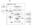
- FIG. 1 is a block diagram showing a configuration of an in-vehicle surveillance camera apparatus according to Embodiment 1 of the present invention.
- the in-vehicle monitoring camera device 100 is mounted on a vehicle.
- a vehicle on which the in-vehicle monitoring camera device 100 is mounted is referred to as “own vehicle”, and another vehicle is referred to as “other vehicle”.
- the camera 1 is connected to the in-vehicle monitoring camera device 100.
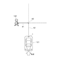
- the camera 1 is provided in the rear part of the own vehicle 101 as shown in FIG.
- the camera 1 is equipped with a wide-angle lens having a wider imaging range than the standard lens.
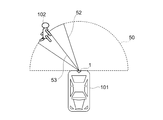
- the wide-angle lens can expand the imaging range up to 180 °. Therefore, the camera 1 can acquire an image of an imaging range with a wide viewing angle, for example, 180 degrees centered on the lens position of the camera 1, as in the imaging range 50 shown in FIG.
- the camera 1 captures the rear of the host vehicle 101 and outputs an image 1.
- the in-vehicle monitoring camera device 100 includes a distortion correction unit 2 as a means for acquiring an image.
- the distortion correction unit 2 receives the image 1 from the camera 1 and obtains the image 2 by removing the distortion of the image 1 caused by the wide-angle lens.
- Various methods have been proposed for removing image distortion caused by a wide-angle lens by image processing, as described in Patent Document 1, for example. Therefore, the distortion correction unit 2 may be configured to remove the distortion of the image 1 using, for example, one of such existing techniques.
- the method of removing the distortion of the image 1 is as follows. There is no particular limitation.
- a millimeter wave radar 11 is connected to the in-vehicle monitoring camera device 100.
- the millimeter wave radar 11 is provided, for example, at the rear part of the host vehicle 101.
- the millimeter wave radar 11 radiates a millimeter wave band and receives a reflected wave reflected by the surface of the obstacle.
- the millimeter wave radar 11 outputs the coordinates of the reflection point as sensing information regarding the obstacle using the reflected wave.
- the in-vehicle monitoring camera device 100 includes an obstacle detection unit 3 and a collision risk determination unit 4 as means for acquiring information on the obstacle.
- the obstacle detection unit 3 receives the sensing information from the millimeter wave radar 11 at a preset period, and specifies a set of coordinates of the reflection point as an obstacle based on the coordinates of the reflection point included in the sensing information. At the same time, the position, path, and speed of the obstacle are detected based on the time-series movement of the set. Further, the obstacle detection unit 3 detects an obstacle that may come into contact with the host vehicle 101 based on the position, route, and speed of the obstacle and the position, route, and speed of the host vehicle 101. Hereinafter, this obstacle is referred to as a “first obstacle”.
- the collision risk determination unit 4 detects the time until the host vehicle 101 comes into contact with the first obstacle detected by the obstacle detection unit 3 and the distance between the first obstacle and the host vehicle.
- the collision risk determination unit 4 determines the course of the host vehicle 101 and the course of the first obstacle 102 based on the position, course, and speed of the first obstacle 102 and the position, course, and speed of the host vehicle 101. Find the intersection point 40 at which. Next, the collision risk determination unit 4 obtains the arrival time A (see reference numeral 41) of the first obstacle 102 to the intersection 40 and the arrival time B (see reference numeral 42) of the host vehicle 101 to the intersection 40. . The collision risk determination unit 4 obtains the smaller one of the arrival time A and the arrival time B as “time until contact”.
- the collision risk determination unit 4 determines the distance between the first obstacle 102 and the own vehicle 101 based on the position of the first obstacle 102 and the position of the own vehicle 101 as “the obstacle and the own vehicle 101”. Calculated as “distance from vehicle”.
- the obstacle 102 is a pedestrian.
- the obstacle 102 is not limited to this, and the obstacle 102 includes a dynamic obstacle such as an animal, a tricycle, a bicycle, a single vehicle, and other vehicles, And static obstacles such as guardrails and utility poles.
- the vehicle-mounted monitoring camera device 100 includes a camera viewpoint display control unit 5 and an obstacle display superimposing unit 7 as means for performing display.
- a viewpoint storage unit 6 is connected to the camera viewpoint display control unit 5.
- the viewpoint storage unit 6 includes a memory.
- the viewpoint storage unit 6 stores obstacle information.
- the obstacle information is, for example, an obstacle ID.
- the camera viewpoint display control unit 5 performs the following three operations (1) to (3).
- the camera viewpoint display control unit 5 determines whether or not the obstacle information is recorded in the viewpoint storage unit 6. If the information is not recorded, the camera viewpoint display control unit 5 detects “contact” detected by the collision risk determination unit 4. The first obstacle having the shortest time is extracted as the second obstacle, and the viewpoint storage unit 6 stores information on the second obstacle.
- the viewpoint display control unit 5 determines whether or not the obstacle information is recorded in the viewpoint storage unit 6. If the information is not recorded, the camera viewpoint display control unit 5 detects “contact” detected by the collision risk determination unit 4. The first obstacle having the shortest time is extracted as the second obstacle, and the viewpoint storage unit 6 stores information on the second obstacle.
- the camera viewpoint display control unit 5 reads the information on the second obstacle from the viewpoint storage unit 6, cuts out the image of the second obstacle from the image 2, and generates the image 3.
- a predetermined fixed range is cut out from the image 2 so that the second obstacle is located at the center in the horizontal direction of the image.
- the certain range is, for example, a preset pixel range.
- the fixed range is a fixed value regardless of the distance to the second obstacle.
- the vertical center of the image is constant regardless of the position of the obstacle. Thereby, as the distance from the host vehicle 101 increases, the position of the obstacle in the image approaches the horizon. In this way, by making the vertical center of the image constant, the driver can easily grasp the distance to the obstacle.
- the camera viewpoint display control unit 5 shows a radar chart 31 indicating the visual field range of the image 3 and the central direction of the visual field so that the driver can grasp the direction of the second obstacle. Is superimposed on the image 3.
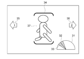
- FIG. 4A shows an example of the radar chart 31.
- the radar chart 31 has a semicircular shape centered on the host vehicle 101.
- the radar chart 31 displays a visual field range 32 of the image 3 and a central direction 33 of the visual field.
- the colored area indicates the visual field range 32
- the solid line indicates the central direction 33 of the visual field.
- the radar chart 31 displays both the visual field range 32 of the image 3 and the central direction 33 of the visual field, but only one of them may be displayed.
- FIG. 4A is compared with FIG.
- reference numeral 50 indicates an imaging range of the camera 1.
- Reference numeral 52 denotes a range displayed as the image 3.
- the range is referred to as a display range or a visual field range of the image 3.
- Reference numeral 53 indicates the direction of the obstacle 102.
- the direction of the obstacle 102 indicates the center direction of the visual field of the image 3.
- the imaging range 50 in FIG. 5 corresponds to the semicircle of the radar chart 31 in FIG. 4A.
- the display range 52 in FIG. 5 corresponds to the visual field range 32 in FIG. 4A.
- the direction 53 in FIG. 5 corresponds to the central direction 33 of the visual field in FIG. 4A.
- the obstacle display superimposing unit 7 sets the time until the second obstacle displayed in the image 3 is contacted with the second obstacle detected by the collision risk determination unit 4 or the second obstacle.
- the image 4 is generated by superimposing the mark whose shape and color can be switched in accordance with the distance up to and output the image 4 to the display device 9.
- a display device 9 and a display device 10 are connected to the in-vehicle monitoring camera device 100.
- the mark is an emphasis display for alerting the driver to the second obstacle displayed in the image 3. Since the mark is changed in shape and color depending on the time or distance until contact, the driver determines the priority of the second obstacle, that is, the urgency level according to the shape and color of the mark. Can be recognized.
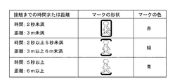
- FIG. 4A shows an example of the mark 34 superimposed on the image 4 (reference numeral 30).
- FIG. 4B shows an example of a data table in which the shape and color of the mark 34 are defined for each time or distance until contact. As shown in FIG. 4B, when the time to contact is within 2 seconds or the distance to contact is less than 3 m, the mark has a rectangular shape and the color of the mark so as to indicate that the priority is high. Is set to red. In addition, when the time to contact is 2 seconds or more and less than 5 seconds or the distance to contact is 3 m or more and less than 6 m, the mark shape is in parentheses to indicate that the priority is medium, and The color of the mark is set to green.
- the in-vehicle monitoring camera device 100 includes a camera output unit 12.
- the camera output unit 12 outputs the image 1 acquired from the camera 1 to the display device 10 as it is in order to display the entire image 1 acquired from the camera 1.
- the driver views the image 4 on the display device 9 and the image 1 on the display device 10 at the same time, so that the image 1 can roughly grasp the entire rear state of the host vehicle 101 with a wide viewing angle of 180 °. 4 makes it possible to accurately grasp the positional relationship of the obstacles.
- the camera viewpoint display control unit 5 further performs the following operation (4).
- an operation device 8 can be connected to the camera viewpoint display control unit 5.
- the camera viewpoint display control unit 5 receives a signal from the operation device 8, and in order of time until the host vehicle 101 contacts the obstacle, in order of distance from the obstacle, or viewpoint to the obstacle A mechanism is provided for changing the obstacle ID stored in the viewpoint storage unit 6 in accordance with any one of the order of the directions. Thereby, when the obstacle currently displayed on the display device 9 is switched to the next obstacle, the driver can specify in what order the next obstacle is selected. Details will be described later.
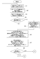
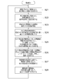
- the distortion correction unit 2 removes distortion due to the wide-angle lens from the image 1 acquired from the camera 1, and generates an image 2 (step S1).
- the obstacle detection unit 3 identifies one or more obstacles based on the set of reflection points from the millimeter wave radar 11 and its time-series movement, and the position and path of those obstacles. Based on the position of the obstacle, the course, the speed and the position, the course, and the speed of the host vehicle, the obstacle that may come into contact with the host vehicle is selected from the obstacles. Are extracted as obstacles (step S2).
- the collision risk determination unit 4 detects the time of contact with the first obstacle by the method shown in FIG. 3, and also detects the distance between the first obstacle and the host vehicle (step S3). At this time, a newly detected obstacle is assigned a new ID, and the previously detected obstacle is assigned the same ID as the previous one.
- the camera viewpoint display control unit 5 reads the obstacle ID stored in the viewpoint storage unit 6 in order to select an obstacle to be displayed on the display device 9, and the obstacle exists in the image 2. (Step S4).
- step S5 If it does not exist, it is assumed that there is no obstacle, and the ID of the obstacle with the shortest time to contact among the detected first obstacles is stored in the viewpoint storage unit 6 (step S5). On the other hand, when it exists, it progresses to step S6 as it is.
- the camera viewpoint display control unit 5 reads the obstacle ID stored in the viewpoint storage unit 6 and sets a preset pixel range so that the corresponding obstacle is in the horizontal center of the image.
- the image 3 is generated by cutting out from the image 2.
- the center in the vertical direction of the image is constant regardless of the position of the obstacle so that the distance to the obstacle can be grasped, and the farther obstacle can be seen to approach the horizon.
- the obstacle display superimposing unit 7 superimposes the semicircular radar chart 31 centering on the own vehicle 101 on the image 3 (step S6).
- the obstacle display superimposing unit 7 changes the mark and the color defined in the table of FIG. 4B so as to change the shape and color of the image 3 according to the time until the collision, as shown in FIG. 4A. 34 is superimposed.
- the mark 34 is superimposed on the pixel range 37 corresponding to the obstacle 102 in the image 3.
- the obstacle display superimposing unit 7 displays left obstacle information and right obstacle information indicating the presence of other obstacles not displayed in the image 3, respectively, as shown in FIG. 4A. Indicated by arrows 35 and 36. Further, numbers indicating the number of obstacles are displayed in the arrows 35 and 36. Thereby, the image 4 shown to FIG. 4A is produced
- an operation device 8 can be connected to the in-vehicle monitoring camera device 100.
- the operation by the driver's operation on the operating device 8 when the operating device 8 is connected to the in-vehicle monitoring camera device 100 will be described after step S8.
- the operation device 8 transmits a signal indicating that there is an operation input to the camera viewpoint display control unit 5 when an operation input for viewpoint switching is made by the driver. For this reason, the camera viewpoint display control unit 5 confirms whether or not there has been a viewpoint switching operation input based on the presence or absence of the signal from the operation device 8 (step S8). If there is an operation input, the process proceeds to step S9 in FIG. 2B. On the other hand, if there is no operation input, the process returns to step S1.
- the camera viewpoint display control unit 5 determines which is the switching order input to the operation device 8 (step S9). For example, there are three switching orders: “order in time until contact”, “order in viewpoint direction”, and “order in distance to an obstacle”.
- step S9 If it is determined in step S9 that the switching order is “time order until contact”, the camera viewpoint display control unit 5 detects the obstacle stored in the viewpoint storage unit 6 among the obstacles detected in step S2. The ID of the obstacle with the shortest time to contact next to the object is stored in the viewpoint storage unit 6 as a display target. However, if there is no corresponding obstacle, the ID of the obstacle with the shortest time to contact is stored in the viewpoint storage unit 6 as a display target (step S10).
- the camera viewpoint display control unit 5 is an obstacle detected in step S2 and is stored in the viewpoint storage unit 6.
- the ID of the obstacle having the closest viewpoint direction is stored in the viewpoint storage unit 6 as a display target.
- the ID of the obstacle on the leftmost side in the viewpoint direction is stored in the viewpoint storage unit 6 (step S11).
- step S9 If it is determined in step S9 that the switching order is “order of distance from an obstacle”, the camera viewpoint display control unit 5 is stored in the viewpoint storage unit 6 among the obstacles detected in step S2.
- the ID of the obstacle having the shortest distance from the host vehicle 101 next to the obstacle is stored in the viewpoint storage unit 6 as a display target.
- the ID of the obstacle with the shortest distance to the host vehicle 101 is stored in the viewpoint storage unit 6 as a display target (step S12).
- step S1 to step S12 is a periodic loop process. After the process is completed up to step S12, the process waits until the timing at which the image 1 of the camera 1 is input, and then the process from step S1 to step S12. The process starts again.
- the obstacle that may collide with the host vehicle 101 is designated as the first obstacle.
- An obstacle detection unit 3 that detects the obstacle
- a collision risk determination unit 4 that detects a time until the first obstacle and the host vehicle 101 come into contact with each other, or a distance between the first obstacle and the host vehicle.
- the first image captured by the wide-angle lens is input, the distortion correction unit 2 that corrects the distortion of the first image to generate the second image, and the time or distance detected by the collision risk determination unit 4 Among them, the first obstacle having the shortest time or the shortest distance is extracted as the second obstacle, and an image in a certain range is displayed so that the second obstacle is located in the center in the horizontal direction.
- a camera that cuts out from an image and generates a third image It includes a point display control unit 5, and a first display device 9 for displaying the third image.
- the camera viewpoint display control unit 5 superimposes the radar chart 31 as an image indicating the visual field range of the third image or the central direction of the visual field of the third image on the third image, so that the second image is displayed. Display the direction of the obstacle. Accordingly, the driver can quickly grasp the detected distance and direction to the obstacle without requiring a display device larger than the standard size display device.
- the radar chart 31 is merely an example, and any radar chart 31 may be used as long as it is an image showing the visual field range of the third image or the central direction of the visual field of the third image.
- the shape of the image is not a semicircular shape as shown in FIG. 4A but may be a circular shape or a rectangular shape.
- the display form and display method of the visual field range 32 and the central direction 33 of the visual field may be other display forms and display methods, for example, the central direction 33 of the visual field is indicated by an arrow.
- the mark 34 as an emphasis display for emphasizing the second obstacle displayed in the third image is applied to the second obstacle in the third image.
- An obstacle display superimposing unit 7 for superimposing is provided. As a result, the driver can instantly grasp the degree of obstacle collision risk.
- the operation device 8 to which a switching instruction for switching the second obstacle displayed in the third image to another one of the first obstacles is input is used. It may be. In this case, the second obstacle displayed in the third image can be switched to another one according to the driver switching instruction.
- the obstacle display superimposing unit 7 indicates the information indicating the presence of the other first obstacle not displayed in the third image by the arrows 35 and 36. May be. In that case, when the driver touches the arrows 35 and 36 with a finger, other obstacles not displayed on the screen can be displayed.
- FIG. FIG. 6 is a block diagram showing a configuration of an in-vehicle monitoring camera device 100A according to Embodiment 2 of the present invention.
- the in-vehicle monitoring camera device 100A is mounted on the host vehicle 101.
- the camera 1 is connected to the in-vehicle monitoring camera device 100A, as in the first embodiment. Similar to the first embodiment, the camera 1 is provided at the rear of the host vehicle 101 as shown in FIG. The camera 1 is equipped with a wide angle lens. Therefore, the camera 1 can acquire an image in an imaging range with a wide viewing angle, for example, 180 ° centered on the camera 1, as in the imaging range 50 illustrated in FIG. 5. The camera 1 captures the rear of the host vehicle 101 and outputs an image 5.
- the in-vehicle monitoring camera device 100A includes a distortion correction unit 2 as the first embodiment as means for acquiring an image to be displayed.
- the distortion correction unit 2 receives the image 5 from the camera 1 and obtains the image 6 by removing the distortion of the image 5 caused by the wide-angle lens in the same manner as in the first embodiment.
- the in-vehicle monitoring camera device 100A includes an obstacle detection unit 63 and a collision risk determination unit 64.
- the obstacle detection unit 3 shown in the first embodiment uses the sensing information of the millimeter wave radar 11.
- the obstacle detection unit 63 in the second embodiment passes through the distortion correction unit 2.
- An image 6 obtained from the camera 1 is used.
- the obstacle detection unit 63 performs image recognition processing on the image 6 to detect the presence of the obstacle, and reverse-projection transforms the pixel coordinates where the obstacle is detected to detect the position of the obstacle. Further, the obstacle detection unit 63 detects the position, course, and speed of the obstacle based on the time-series change in the position of the obstacle included in the image 6 obtained by the past image processing.
- the collision risk determination unit 64 Based on the position, path, and speed of the obstacle and the position, path, and speed of the host vehicle 101, an obstacle that may come into contact with the host vehicle 101 is detected as the first obstacle.
- the collision risk determination unit 64 detects “time until contact” and “distance between the obstacle and the host vehicle” by the same detection method as the collision risk determination unit 4 described in the first embodiment.
- the in-vehicle monitoring camera device 100A includes a camera viewpoint display control unit 65 and an obstacle display superimposing unit 66 as means for performing display.
- the camera viewpoint display control unit 65 performs the following three operations (1) to (3).
- the camera viewpoint display control unit 65 extracts a maximum of four obstacles in order from the shortest distance among the obstacles detected by the obstacle detection unit 63.
- the camera viewpoint display control unit 65 generates an image 7 for each extracted obstacle by cutting out a certain range from the image 6 so that the obstacle is positioned at the center in the horizontal direction of the image. To do. Since the image 7 is generated for each obstacle, the number of the images 7 is a maximum of four.
- the certain range is, for example, a preset pixel range. The vertical center of the image is constant regardless of the position of the obstacle so that the distance to the obstacle can be grasped, as in the first embodiment.
- the camera viewpoint display control unit 65 superimposes the radar chart 31 as an image indicating the visual field range of the image 7 or the central direction of the visual field on the image 7. Since the radar chart 31 is the same as the radar chart 31 described in the first embodiment, the description thereof is omitted here.
- the obstacle display superimposing unit 66 generates an image 8 in which the mark 34 whose shape and color change is superimposed on the obstacle of the image 7 according to the distance between the obstacle and the host vehicle, and generates four display devices. 67, 68, 69 and 70, respectively.
- the shape and color of the mark are defined in advance in the data table of FIG. 4B, for example.
- the example of the image 8 may be the same as the image 4 (reference numeral 30) illustrated in FIG. 4A, for example.
- the distortion correction unit 2 removes image distortion caused by the wide-angle lens from the image 5 acquired from the camera 1, and generates an image 6 (step S21).
- the obstacle detection unit 63 uses the image 6 to detect the presence and position of the first obstacle by image recognition processing (step S22).
- the collision risk determination unit 64 detects the distance between the first obstacle and the host vehicle 101 (step S23). .
- the camera viewpoint display control unit 65 extracts a maximum of four obstacles as second obstacles in the order of short time or distance until contact with the host vehicle 101 in the first obstacle. (Step S24).
- the number of first obstacles is four or less
- the number of second obstacles to be extracted is the same as the number of first obstacles.
- the camera viewpoint display control unit 65 displays an image in a certain range so that the second obstacle is the center in the horizontal direction of the image. 7 is cut out (step S25).
- the number of images 7 is the same as the number of second obstacles.
- the fixed range is, for example, a preset pixel range as in the first embodiment.
- the camera viewpoint display control unit 65 superimposes the radar chart 31 indicating the field-of-view range or the center direction of the field of view on each image 7 (step S26).
- the number of images 8 is the same as the number of second obstacles.
- the obstacle display superimposing unit 66 outputs each image 8 to the external display devices 67, 68, 69, 70 (step S28).
- step S21 to step S28 is a periodic loop process starting from the input of the image 5 from the camera 1. After the process is completed up to step S28, the image 5 from the camera 1 is input. The process from step S21 to step S28 is started again after waiting for the timing.
- the camera output unit 12 and the display device 10 shown in FIG. 1 are not provided, but the camera output unit 12 and the display device 10 shown in FIG. Thus, the image 5 may be displayed.
- the operating device 8 shown in FIG. 1 is not provided, but in the second embodiment as well, the operating device 8 shown in FIG. 1 is provided and obstructions are made according to the switching order designated by the driver. May be switched.
- the obstacle detection unit 63 that detects an obstacle that may collide with the host vehicle as the first obstacle
- a collision risk determination unit 64 that detects a time until the first obstacle comes into contact with the host vehicle 101 or a distance between the first obstacle and the host vehicle, and a first image taken by a wide-angle lens.
- the distortion correction unit 2 that corrects the distortion of the first image to generate the second image
- a first obstacle is extracted as a second obstacle, an image of a certain range is cut out from the second image so that the second obstacle is located in the center in the horizontal direction, and a third image is obtained.
- the camera viewpoint display control unit 65 to be generated and the third image are displayed. And a first display device 67-70 to.
- the camera viewpoint display control unit 5 converts the radar chart 31 as an image indicating the visual field range of the third image with respect to the imaging range of the first image or the center direction of the visual field of the third image into the third image. By superimposing, the direction of the second obstacle is displayed. Thereby, the effect similar to Embodiment 1 can be acquired.
- the camera viewpoint display control unit 5 extracts a plurality of first obstacles as the second obstacle, and generates a third image for each first obstacle. To do. Further, a plurality of display devices 67 to 70 are provided as display devices, and the third images generated for the respective first obstacles are displayed on the screens of the display devices 67 to 70, respectively. Accordingly, the driver can display a plurality of obstacles on the display device without switching the screen.
Landscapes
- Engineering & Computer Science (AREA)
- Mechanical Engineering (AREA)
- Transportation (AREA)
- Combustion & Propulsion (AREA)
- Chemical & Material Sciences (AREA)
- Automation & Control Theory (AREA)
- Physics & Mathematics (AREA)
- General Physics & Mathematics (AREA)
- Theoretical Computer Science (AREA)
- Multimedia (AREA)
- Human Computer Interaction (AREA)
- Signal Processing (AREA)
- Closed-Circuit Television Systems (AREA)
- Traffic Control Systems (AREA)
- Image Processing (AREA)
- Image Analysis (AREA)
Abstract
La présente invention concerne un dispositif caméra de surveillance embarqué (100) comprenant : une unité de détection d'obstacle (3) qui détecte, en tant que premiers obstacles, des obstacles détectés par un radar à ondes millimétriques (11) qui pourraient entrer en collision avec le véhicule hôte ; une unité de détermination de risques de collision (4) qui détecte le moment où les premiers obstacles respectifs et le véhicule entrent en contact mutuel ; une unité de correction de distorsion (2) qui génère une image 2 par correction de la distorsion dans une image 1 capturée à l'aide d'un objectif grand-angulaire ; et une unité de commande d'affichage de point de vue de caméra (5) qui génère une image 3 par découpe, à partir de l'image 2, d'une image du premier obstacle qui présente le délai à une collision le plus court. Une carte radar (31) indiquant la plage de champ visuel ou la direction centrale du champ visuel de l'image 3 est superposée sur l'image 3.
Priority Applications (5)
| Application Number | Priority Date | Filing Date | Title |
|---|---|---|---|
| PCT/JP2017/017826 WO2018207303A1 (fr) | 2017-05-11 | 2017-05-11 | Dispositif caméra de surveillance embarqué |
| DE112017007528.9T DE112017007528B4 (de) | 2017-05-11 | 2017-05-11 | Fahrzeugüberwachungskameravorrichtung |
| JP2019516811A JP6785953B2 (ja) | 2017-05-11 | 2017-05-11 | 車載用監視カメラ装置 |
| US16/603,962 US11214248B2 (en) | 2017-05-11 | 2017-05-11 | In-vehicle monitoring camera device |
| CN201780090475.6A CN110612562B (zh) | 2017-05-11 | 2017-05-11 | 车载用监视摄像头装置 |
Applications Claiming Priority (1)
| Application Number | Priority Date | Filing Date | Title |
|---|---|---|---|
| PCT/JP2017/017826 WO2018207303A1 (fr) | 2017-05-11 | 2017-05-11 | Dispositif caméra de surveillance embarqué |
Publications (1)
| Publication Number | Publication Date |
|---|---|
| WO2018207303A1 true WO2018207303A1 (fr) | 2018-11-15 |
Family
ID=64105305
Family Applications (1)
| Application Number | Title | Priority Date | Filing Date |
|---|---|---|---|
| PCT/JP2017/017826 Ceased WO2018207303A1 (fr) | 2017-05-11 | 2017-05-11 | Dispositif caméra de surveillance embarqué |
Country Status (5)
| Country | Link |
|---|---|
| US (1) | US11214248B2 (fr) |
| JP (1) | JP6785953B2 (fr) |
| CN (1) | CN110612562B (fr) |
| DE (1) | DE112017007528B4 (fr) |
| WO (1) | WO2018207303A1 (fr) |
Cited By (4)
| Publication number | Priority date | Publication date | Assignee | Title |
|---|---|---|---|---|
| CN111506052A (zh) * | 2019-01-14 | 2020-08-07 | 上海博泰悦臻网络技术服务有限公司 | 障碍物的监控方法、系统、计算机存储介质及车载终端 |
| WO2020261823A1 (fr) * | 2019-06-27 | 2020-12-30 | 株式会社クボタ | Système de détection d'obstacle, véhicule de travail agricole, programme de détection d'obstacle, support d'enregistrement sur lequel un programme de détection d'obstacle est enregistré, et procédé de détection d'obstacle |
| CN115009172A (zh) * | 2022-04-20 | 2022-09-06 | 北京易航远智科技有限公司 | 车载环视系统的视角切换方法、系统、电子设备和介质 |
| JP2022133832A (ja) * | 2021-03-02 | 2022-09-14 | 住友ナコ フォ-クリフト株式会社 | 作業車両の周辺監視装置および作業車両 |
Families Citing this family (15)
| Publication number | Priority date | Publication date | Assignee | Title |
|---|---|---|---|---|
| EP3584120B1 (fr) * | 2017-02-17 | 2021-04-14 | Sumitomo Heavy Industries, Ltd. | Système de surveillance d'environnement de machine de travail |
| JP6983309B2 (ja) * | 2018-04-16 | 2021-12-17 | 三菱電機株式会社 | 障害物検出装置、障害物検出装置を利用した自動ブレーキ装置、障害物検出方法、および障害物検出方法を利用した自動ブレーキ方法 |
| US12013243B2 (en) * | 2019-04-05 | 2024-06-18 | FLIR Belgium BVBA | Passage planning and navigation systems and methods |
| JP7308089B2 (ja) * | 2019-07-18 | 2023-07-13 | 株式会社小松製作所 | 作業車両の表示システムおよび作業車両の表示方法 |
| DE102019213423A1 (de) * | 2019-09-04 | 2021-03-04 | Robert Bosch Gmbh | Verfahren und Vorrichtung zum Betreiben eines automatisierten Fahrzeugs |
| KR20210054107A (ko) * | 2019-11-04 | 2021-05-13 | 현대자동차주식회사 | 차량의 디스플레이 장치 및 방법 |
| US11615542B2 (en) * | 2019-11-14 | 2023-03-28 | Panasonic Avionics Corporation | Automatic perspective correction for in-flight entertainment (IFE) monitors |
| US11594144B2 (en) * | 2020-01-31 | 2023-02-28 | Honeywell International Inc. | Collision awareness using cameras mounted on a vehicle |
| JP7718810B2 (ja) * | 2020-12-02 | 2025-08-05 | ヤンマーホールディングス株式会社 | 自動走行システム、自動走行方法、及び自動走行プログラム |
| US11733369B2 (en) * | 2021-02-11 | 2023-08-22 | Waymo Llc | Methods and systems for three dimensional object detection and localization |
| CN113184704A (zh) * | 2021-04-28 | 2021-07-30 | 徐州重型机械有限公司 | 安全控制系统、方法、控制装置和起重机 |
| JP7517252B2 (ja) * | 2021-06-04 | 2024-07-17 | トヨタ自動車株式会社 | 車両用表示装置、車両用表示システム、車両用表示方法及びプログラム |
| KR102615479B1 (ko) * | 2021-11-24 | 2023-12-19 | 현대모비스 주식회사 | 램프 및 그것의 동작 방법, 차량 |
| KR20240098756A (ko) * | 2022-12-21 | 2024-06-28 | 부산대학교 산학협력단 | 주변 색상에 따라 색이 변하는 전자잉크 안전모 시스템 및 운영방법 |
| JP7651604B2 (ja) | 2023-03-31 | 2025-03-26 | 本田技研工業株式会社 | 交通安全支援システム |
Citations (5)
| Publication number | Priority date | Publication date | Assignee | Title |
|---|---|---|---|---|
| JP2006054662A (ja) * | 2004-08-11 | 2006-02-23 | Mitsubishi Electric Corp | 運転支援装置 |
| JP2008230476A (ja) * | 2007-03-22 | 2008-10-02 | Denso Corp | 車両外部撮影表示システムおよび画像表示制御装置 |
| JP2009023565A (ja) * | 2007-07-20 | 2009-02-05 | Denso It Laboratory Inc | 運転支援装置および運転支援方法 |
| JP2009067292A (ja) * | 2007-09-14 | 2009-04-02 | Hitachi Ltd | 車載カメラシステム |
| JP2012227699A (ja) * | 2011-04-19 | 2012-11-15 | Toyota Motor Corp | 画像表示装置、及び、画像表示方法 |
Family Cites Families (9)
| Publication number | Priority date | Publication date | Assignee | Title |
|---|---|---|---|---|
| JP2006178667A (ja) | 2004-12-21 | 2006-07-06 | Nissan Motor Co Ltd | 車両用映像補正装置及び車両用映像補正方法 |
| KR100724134B1 (ko) * | 2006-01-09 | 2007-06-04 | 삼성전자주식회사 | 이미지 매칭 속도와 블렌딩 방법을 개선한 파노라마 영상제공 방법 및 장치 |
| US8633810B2 (en) * | 2009-11-19 | 2014-01-21 | Robert Bosch Gmbh | Rear-view multi-functional camera system |
| JP5414714B2 (ja) * | 2011-03-04 | 2014-02-12 | 日立オートモティブシステムズ株式会社 | 車戴カメラ及び車載カメラシステム |
| CN103609101A (zh) * | 2011-06-16 | 2014-02-26 | 爱信精机株式会社 | 车辆周边监视装置 |
| JP2015022340A (ja) | 2013-07-16 | 2015-02-02 | スズキ株式会社 | 運転支援装置 |
| US20150109444A1 (en) * | 2013-10-22 | 2015-04-23 | GM Global Technology Operations LLC | Vision-based object sensing and highlighting in vehicle image display systems |
| JP2016075818A (ja) | 2014-10-07 | 2016-05-12 | 株式会社デンソー | 情報表示装置および情報表示方法 |
| JP6752024B2 (ja) * | 2016-02-12 | 2020-09-09 | 日立オートモティブシステムズ株式会社 | 画像処理装置 |
-
2017
- 2017-05-11 WO PCT/JP2017/017826 patent/WO2018207303A1/fr not_active Ceased
- 2017-05-11 CN CN201780090475.6A patent/CN110612562B/zh active Active
- 2017-05-11 DE DE112017007528.9T patent/DE112017007528B4/de not_active Expired - Fee Related
- 2017-05-11 JP JP2019516811A patent/JP6785953B2/ja active Active
- 2017-05-11 US US16/603,962 patent/US11214248B2/en not_active Expired - Fee Related
Patent Citations (5)
| Publication number | Priority date | Publication date | Assignee | Title |
|---|---|---|---|---|
| JP2006054662A (ja) * | 2004-08-11 | 2006-02-23 | Mitsubishi Electric Corp | 運転支援装置 |
| JP2008230476A (ja) * | 2007-03-22 | 2008-10-02 | Denso Corp | 車両外部撮影表示システムおよび画像表示制御装置 |
| JP2009023565A (ja) * | 2007-07-20 | 2009-02-05 | Denso It Laboratory Inc | 運転支援装置および運転支援方法 |
| JP2009067292A (ja) * | 2007-09-14 | 2009-04-02 | Hitachi Ltd | 車載カメラシステム |
| JP2012227699A (ja) * | 2011-04-19 | 2012-11-15 | Toyota Motor Corp | 画像表示装置、及び、画像表示方法 |
Cited By (8)
| Publication number | Priority date | Publication date | Assignee | Title |
|---|---|---|---|---|
| CN111506052A (zh) * | 2019-01-14 | 2020-08-07 | 上海博泰悦臻网络技术服务有限公司 | 障碍物的监控方法、系统、计算机存储介质及车载终端 |
| WO2020261823A1 (fr) * | 2019-06-27 | 2020-12-30 | 株式会社クボタ | Système de détection d'obstacle, véhicule de travail agricole, programme de détection d'obstacle, support d'enregistrement sur lequel un programme de détection d'obstacle est enregistré, et procédé de détection d'obstacle |
| JP2021006011A (ja) * | 2019-06-27 | 2021-01-21 | 株式会社クボタ | 農作業車のための障害物検出システム |
| JP7565677B2 (ja) | 2019-06-27 | 2024-10-11 | 株式会社クボタ | 農作業車のための障害物検出システム |
| US12223739B2 (en) | 2019-06-27 | 2025-02-11 | Kubota Corporation | Obstacle detection system, agricultural work vehicle, obstacle detection program, recording medium on which obstacle detection program is recorded, and obstacle detection method |
| JP2022133832A (ja) * | 2021-03-02 | 2022-09-14 | 住友ナコ フォ-クリフト株式会社 | 作業車両の周辺監視装置および作業車両 |
| JP7642401B2 (ja) | 2021-03-02 | 2025-03-10 | 住友ナコ フォ-クリフト株式会社 | 作業車両の周辺監視装置および作業車両 |
| CN115009172A (zh) * | 2022-04-20 | 2022-09-06 | 北京易航远智科技有限公司 | 车载环视系统的视角切换方法、系统、电子设备和介质 |
Also Published As
| Publication number | Publication date |
|---|---|
| CN110612562B (zh) | 2022-02-25 |
| CN110612562A (zh) | 2019-12-24 |
| JP6785953B2 (ja) | 2020-11-18 |
| DE112017007528B4 (de) | 2024-10-02 |
| DE112017007528T5 (de) | 2020-01-23 |
| JPWO2018207303A1 (ja) | 2019-11-07 |
| US20200148203A1 (en) | 2020-05-14 |
| US11214248B2 (en) | 2022-01-04 |
Similar Documents
| Publication | Publication Date | Title |
|---|---|---|
| JP6785953B2 (ja) | 車載用監視カメラ装置 | |
| US8461976B2 (en) | On-vehicle device and recognition support system | |
| US8330816B2 (en) | Image processing device | |
| JP6307895B2 (ja) | 車両用周辺監視装置 | |
| JP4434224B2 (ja) | 走行支援用車載装置 | |
| JP5347257B2 (ja) | 車両用周辺監視装置および映像表示方法 | |
| US20110228980A1 (en) | Control apparatus and vehicle surrounding monitoring apparatus | |
| JP4985250B2 (ja) | 駐車支援装置 | |
| JP6744236B2 (ja) | 画像表示装置 | |
| JP5054612B2 (ja) | 接近物検出装置および接近物検出方法 | |
| CN111273765A (zh) | 车辆用显示控制装置、车辆用显示控制方法以及存储介质 | |
| JP2018022234A (ja) | 画像処理装置、外界認識装置 | |
| JP2015197706A (ja) | 車両用表示制御装置 | |
| JP2009231938A (ja) | 車両用周囲監視装置 | |
| TW201904282A (zh) | 攝像裝置、攝像模組及攝像裝置之控制方法 | |
| US10579884B2 (en) | Image processing device and image processing method | |
| JP5691814B2 (ja) | 運転支援装置 | |
| JP2013161440A (ja) | 車両周辺監視装置 | |
| JP2019197270A (ja) | 物体検知装置および物体検知方法 | |
| JP6555240B2 (ja) | 車両用撮影表示装置及び車両用撮影表示プログラム | |
| JP4848644B2 (ja) | 障害物認識システム | |
| JP5950193B2 (ja) | 視差値演算装置及びこれを備えた視差値演算システム、移動面領域認識システム、視差値演算方法、並びに、視差値演算用プログラム | |
| JP2013171391A (ja) | 車両周辺監視システム | |
| US12380710B2 (en) | System and method for deep learning based lane curvature detection from 2D images | |
| JP2006208256A (ja) | 車載用電子装置 |
Legal Events
| Date | Code | Title | Description |
|---|---|---|---|
| 121 | Ep: the epo has been informed by wipo that ep was designated in this application |
Ref document number: 17908834 Country of ref document: EP Kind code of ref document: A1 |
|
| ENP | Entry into the national phase |
Ref document number: 2019516811 Country of ref document: JP Kind code of ref document: A |
|
| 122 | Ep: pct application non-entry in european phase |
Ref document number: 17908834 Country of ref document: EP Kind code of ref document: A1 |