WO2018207724A1 - Compresseur - Google Patents
Compresseur Download PDFInfo
- Publication number
- WO2018207724A1 WO2018207724A1 PCT/JP2018/017607 JP2018017607W WO2018207724A1 WO 2018207724 A1 WO2018207724 A1 WO 2018207724A1 JP 2018017607 W JP2018017607 W JP 2018017607W WO 2018207724 A1 WO2018207724 A1 WO 2018207724A1
- Authority
- WO
- WIPO (PCT)
- Prior art keywords
- oil
- seal space
- crank chamber
- drive shaft
- discharge passage
- Prior art date
- Legal status (The legal status is an assumption and is not a legal conclusion. Google has not performed a legal analysis and makes no representation as to the accuracy of the status listed.)
- Ceased
Links
Images




Classifications
-
- F—MECHANICAL ENGINEERING; LIGHTING; HEATING; WEAPONS; BLASTING
- F04—POSITIVE - DISPLACEMENT MACHINES FOR LIQUIDS; PUMPS FOR LIQUIDS OR ELASTIC FLUIDS
- F04B—POSITIVE-DISPLACEMENT MACHINES FOR LIQUIDS; PUMPS
- F04B27/00—Multi-cylinder pumps specially adapted for elastic fluids and characterised by number or arrangement of cylinders
- F04B27/08—Multi-cylinder pumps specially adapted for elastic fluids and characterised by number or arrangement of cylinders having cylinders coaxial with, or parallel or inclined to, main shaft axis
- F04B27/10—Multi-cylinder pumps specially adapted for elastic fluids and characterised by number or arrangement of cylinders having cylinders coaxial with, or parallel or inclined to, main shaft axis having stationary cylinders
- F04B27/12—Multi-cylinder pumps specially adapted for elastic fluids and characterised by number or arrangement of cylinders having cylinders coaxial with, or parallel or inclined to, main shaft axis having stationary cylinders having plural sets of cylinders or pistons
-
- F—MECHANICAL ENGINEERING; LIGHTING; HEATING; WEAPONS; BLASTING
- F04—POSITIVE - DISPLACEMENT MACHINES FOR LIQUIDS; PUMPS FOR LIQUIDS OR ELASTIC FLUIDS
- F04B—POSITIVE-DISPLACEMENT MACHINES FOR LIQUIDS; PUMPS
- F04B39/00—Component parts, details, or accessories, of pumps or pumping systems specially adapted for elastic fluids, not otherwise provided for in, or of interest apart from, groups F04B25/00 - F04B37/00
- F04B39/02—Lubrication
Definitions
- the present invention relates to a compressor used in a vehicle air conditioner and the like, and has improved the path structure of oil (lubricating oil) supplied to a shaft sealing member that is provided around a drive shaft and seals between a housing and a housing.
- oil lubricating oil
- the present invention relates to a compressor having a route structure.
- a drive shaft that passes through the crank chamber and is rotatably supported by the housing, and is arranged in the crank chamber and rotates in synchronization with the rotation of the drive shaft, and is rotatably supported on the inner wall surface of the housing via a thrust bearing.
- a radial bearing that receives the drive shaft and a shaft seal member that prevents fluid leakage in the crank chamber are disposed. In such a compressor, good lubrication is required to prevent seizure at the sliding contact portion between the drive shaft and the shaft seal member.
- the inlet opening to the seal space of the oil discharge passage is above the lowest position in contact with the shaft seal member of the drive shaft and is placed at the same level as the horizontal plane including the axis of the drive shaft.
- the oil in the seal space is maintained at an appropriate amount to avoid oil shortage and ensure good lubrication, and to promote the replacement of oil supplied to the shaft seal member
- a compressor has been proposed in which a decrease in shaft seal function (oil leakage) due to a temperature rise of the shaft seal member is suppressed (see Patent Document 3).
- the present invention has been made in view of such circumstances, and avoids the shortage of oil in the seal space while ensuring the flow of oil in the seal space even during operation where the oil in the crank chamber is deficient during high-speed rotation. Therefore, the main object is to provide a compressor capable of maintaining good lubrication of the shaft seal member.
- a compressor includes a housing that defines a crank chamber, and is rotatably supported by the housing through a radial bearing that penetrates the crank chamber.
- a drive shaft protruding from the housing; a shaft sealing member disposed on one end side of the radial bearing of the drive shaft; sealing the space between the drive shaft and the housing;
- An oil supply passage that communicates with the crank chamber, the other end communicates with a seal space formed between the radial bearing and the shaft seal member, one end communicates with the seal space, and the other end communicates with the crank chamber.
- An oil discharge passage that communicates with the oil discharge passage, and an inlet opening to the seal space of the oil discharge passage is at a position above a horizontal plane including the axis of the drive shaft. It is characterized in that it is mouth.
- the oil in the seal space of the oil discharge passage is opened at a position above the horizontal plane including the axis of the drive shaft, the oil in the seal space is scraped off during high speed rotation, etc. Even if it flows out from the passage to the crank chamber, it is possible to leave sufficient oil in the seal space. For this reason, even if there is a lack of oil in the crank chamber and less oil is introduced into the seal space from the oil supply passage, the oil in the seal space can be retained in abundantly, and good lubrication of the shaft seal member is achieved. Can be maintained. Further, although the oil discharge passage is open to the seal space at a position above the horizontal plane including the axis of the drive shaft, the oil in the seal space can be sent to the crank chamber. It does not hinder the flow of oil inside.
- the area of the inlet of the oil discharge passage may be smaller than the area of the outlet of the oil supply passage that opens into the seal space.
- the sum of the areas of the inlets of the respective oil discharge passages opened in the seal space is smaller than the area of the outlets opened in the seal space of the oil supply passage. It is good to do so.
- the inlet of the oil discharge passage is Preferably, the oil supply passage is opened on the rear side in the rotational direction of the drive shaft from the position of the outlet opening in the seal space of the oil supply passage.
- the oil in the crank chamber is not guided to the inside of the thrust bearing.
- the oil supply passage (avoids the disadvantage that a part of oil bypasses the oil supply passage to reduce the amount of oil guided to the seal space), and then thrusts through the oil discharge passage. It is good to make it the structure led to the inside of a bearing.
- one end of the oil supply passage communicates with the crank chamber, the other end communicates with the seal space formed between the radial bearing and the shaft seal member, and one end of the seal space.
- the inlet opening to the seal space of the oil discharge passage is above the horizontal plane including the axis of the drive shaft
- the opening of the shaft seal member prevents the lack of oil in the seal space while ensuring the flow of oil in the seal space even during operation where the oil in the crank chamber is deficient during high-speed rotation. It is possible to ensure good lubrication.
- the area of the inlet of the oil discharge passage smaller than the area of the outlet opening in the seal space of the oil supply passage, it becomes easier to hold oil in the seal space, and there is insufficient oil in the seal space. Can be further avoided.
- the oil introduced into the seal space from the oil supply passage by opening the inlet of the oil discharge passage to the rear side in the rotational direction of the drive shaft from the position of the outlet opening in the seal space of the oil supply passage. Can be prevented from flowing out from the oil discharge passage to the crank chamber without contributing to lubrication or cooling of the shaft seal member.
- FIG. 1 is a cross-sectional view illustrating a compressor according to an embodiment of the present invention.
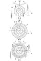
- FIG. 2 is an enlarged cross-sectional view of a part of the front head of the compressor shown in FIG. 3A is a cross-sectional view taken along the line AA in FIG. 2
- FIG. 3B is a cross-sectional view taken along the line BB in FIG. 2
- FIG. 3 is a cross-sectional view taken along the line CC of FIG. 4A and 4B are diagrams for explaining the flow of oil into the seal space and the oil storage state.
- FIG. 4A is a cross-sectional view taken along the line BB in FIG. 2, and FIG. It is sectional drawing to which some front heads of the compressor of this were expanded.
- FIG. 4A is a cross-sectional view taken along the line BB in FIG. 2, and FIG. It is sectional drawing to which some front heads of the compressor of this were expanded.
- FIG. 4A is a cross-sectional view taken along the line BB
- FIG. 5 is a view showing another example of the oil discharge passage, (a) is a cross-sectional view corresponding to a cut portion taken along the line BB of FIG. 2, and (b) is a cross-sectional view of FIG. It is sectional drawing corresponding to the cut part of C line.
- FIG. 6 is a sectional view showing another compressor according to the embodiment of the present invention.
- FIG. 1 shows a variable capacity swash plate compressor used in a refrigeration cycle as an example of a compressor.
- This compressor includes a cylinder block 1, a rear head 3 assembled on the rear side (right side in the figure) of the cylinder block 1 via a valve plate 2, and a front side (left side in the figure) of the cylinder block 1. And a front head 4 assembled so as to be closed.
- the front head 4, the cylinder block 1, the valve plate 2, and the rear head 3 are fastened in the axial direction by fastening bolts 5 and constitute a housing for the entire compressor.
- a crankshaft 6 provided by the front head 4 and the cylinder block 1 accommodates a drive shaft 7 having one end protruding from the front head 4.
- a drive pulley (not shown) connected to the engine of the vehicle via a belt is fixed to a portion of the drive shaft 7 protruding from the front head 4.
- one end side of the drive shaft 7 is hermetically sealed with the front head 4 via a shaft sealing member 10 provided between the drive shaft 7 and the refrigerant leakage along the drive shaft 7 is prevented.
- One end side of the drive shaft 7 is rotatably supported by a radial bearing 11 accommodated on the crank chamber side of the shaft seal member 10 of the front head 4, and the other end side of the drive shaft 7 is supported by the cylinder block 1. Is rotatably supported by a radial bearing 12 housed in the housing.
- the cylinder block 1 is formed with a support hole 13 in which the radial bearing 12 is accommodated, and a plurality of cylinder bores 15 arranged at equal intervals on a circumference around the support hole 13.
- a single-head piston 16 is inserted into the cylinder bore 15 so as to be slidable back and forth.
- the one-head piston 16 is formed by joining a head portion 16a inserted into the cylinder bore 15 and an engaging portion 16b protruding into the crank chamber 6 in the axial direction.
- a thrust flange 17 that rotates integrally with the drive shaft 7 is fixed to the drive shaft 7 in the crank chamber 6.
- the thrust flange 17 is rotatably supported via an annular thrust bearing 18 with respect to the inner wall surface 4 a of the front head 4 formed substantially perpendicular to the drive shaft 7.
- the thrust flange 17 constitutes a power transmission member, and the thrust flange 17 is connected to a swash plate 20 via a link mechanism 19.
- the swash plate 20 is attached so as to be able to tilt around a hinge ball 21 slidably provided on the drive shaft 7, and is integrated with the rotation of the thrust flange 17 via the link mechanism 19. It is designed to rotate. And the engaging part 16b of the single-headed piston 16 is moored to the peripheral part of the swash plate 20 via a pair of shoes 22 arranged at the front and back.
- Reference numeral 24 denotes a suction hole formed in the valve plate 2 that communicates the suction chamber 25 formed in the rear head 3 and the compression chamber 23 via a suction valve (not shown), and 26 denotes a hole formed in the rear head 3. This is a discharge hole formed in the valve plate 2 that communicates the discharge chamber 27 and the compression chamber 23 via a discharge valve (not shown).
- Reference numeral 28 denotes a pressure control valve that controls the communication state between the discharge chamber 27 and the crank chamber 6 and adjusts the crank chamber pressure to adjust the tilt angle of the swash plate 20.
- the shaft seal member 10 and the radial bearing 11 are disposed with a space therebetween in the axial direction, and a shaft seal is provided between the inner surface of the front head 4 and the outer peripheral surface of the drive shaft 7.
- An annular seal space 30 defined by the member 10 and the radial bearing 11 is formed. That is, the seal space 30 is defined by being surrounded by the radial bearing 11, the shaft sealing member 10, the inner surface of the boss portion 41 of the front head 4, and the outer peripheral surface of the drive shaft 7.
- the inner surface of the boss portion 41 of the front head 4 that defines the seal space 30 includes a conical surface 30a whose inner diameter gradually increases from the radial bearing 11 toward the shaft sealing member 10, and a cylindrical surface 30b that follows the conical surface 30a. ing.
- the front head 4 also has a bearing surface for receiving the thrust bearing 18 on the inner wall surface 4a located above the drive shaft 7, more specifically, the thrust bearing 18 is held by the needle roller 18a and this as shown.
- a guide groove 31 for guiding oil is formed on the surface of the front head 4 that receives the thrust trace 18b.
- the guide groove is formed by a pair of grooves extending obliquely on the inner surface of the front head 4 toward an oil supply passage 32 (described later) formed in the front head 4.
- the oil that is formed and scraped up by the swash plate in the crank chamber and flows down along the inner surface of the front head is widely received and concentrated toward the oil supply passage.
- the guide groove 31 and the seal space 30 are connected by an oil supply passage 32 formed in the front head 4 at a predetermined angle with respect to the axis of the drive shaft 7.
- the oil introduced into the guide groove 31 is supplied to the seal space 30.
- the thrust flange 17 is opposed to the inner wall surface 4a of the front head 4 while being separated via a thrust bearing 18, and a gap 33 is formed between the thrust flange 17 and the inner wall surface 4a of the front head 4.
- the gap 33 between the thrust flange 17 and the inner wall surface 4 a is closed by the thrust trace 18 b of the thrust bearing 18. Therefore, the oil descending through the guide groove 31 does not flow into the gap 33 (inside the thrust bearing 18) between the thrust flange 17 and the inner wall surface 4a of the front head 4, and most of the oil is supplied. It is introduced into the passage 32.
- the outlet 32a of the oil supply passage 32 is connected to the seal space 30 only at the conical surface 30a, and is opened at a position where the introduced oil does not directly hit the shaft seal member 10. That is, the conical surface 30a is not located at a position overlapping the shaft seal member 10 in the axial direction, and is formed so as to be shifted to a portion closer to the radial bearing 11 than the shaft seal member 10 by a predetermined dimension.
- the front head 4 further has an oil discharge passage 34 having one end communicating with the seal space 30 and the other end communicating with the crank chamber 6 (in this example, the gap 33 communicating with the crank chamber 6).
- the oil discharge passage 34 is formed substantially parallel to the drive shaft 7, and a part or all of the inflow port 34 a (one end of the oil discharge passage 34) that opens into the seal space 30 is on the conical surface 30 a.
- all of the inflow ports 34a are formed so as to open at the conical surface 30a).
- the opening is opened at a position above the horizontal plane ⁇ including the axis O of the drive shaft 7.
- the area of the inlet 34 a that opens to the seal space 30 of the oil discharge passage 34 is formed smaller than the area of the outlet 32 a that opens to the seal space of the oil supply passage 32.
- the inlet 34a of the oil discharge passage 34 has a drive shaft more than the position of the outlet 32a that opens into the seal space 30 of the oil supply passage 32 as a reference. 7 is opened to the rear side in the rotation direction (direction indicated by an arrow in the figure).
- the other end of the oil discharge passage 34 opens to the inner wall surface 4a of the front head 4 on the inner side of the thrust bearing 18 (on the drive shaft side than the thrust bearing 18).
- the thrust bearing 18 is guided to the gap 33 between the thrust flange on the inner side of the thrust bearing 18 and the inner wall surface 4a of the front head 4, and then guided to the sliding portion (radial bearing 11) inside the thrust bearing 18 and It is made to return to the crank chamber 6 through a gap.
- the inner peripheral surface of the seal space 30 is formed as a conical surface 30 a that expands toward the shaft seal member 10, the oil guided to the seal space 30 is around the drive shaft 7 before the shaft seal member 10. Or, it is guided to the lower side of the drive shaft 7 along the inner surface of the boss portion 41 of the front head 4, and then guided to the shaft seal member 10 along the conical surface 30 a.
- the oil discharge passage 34 opens in the seal space at a position above the horizontal plane including the axis O of the drive shaft 7, the oil stored in the seal space 30 as shown in FIG. 4. Until the height of the inlet 34a of the oil discharge passage 34 is raised or the oil level does not reach the inlet 34a, the oil in the seal space 30 is not discharged. Accordingly, even when the crank chamber oil is deficient during high-speed rotation, the oil stored in the seal space 30 is not easily discharged from the seal space 30 and can be held in the seal space.
- the oil flowing down through the guide groove is not directly guided to the inner side of the thrust bearing 18 (the gap 33 between the thrust flange 17 and the inner wall surface 4a of the front head 4), but first through the oil supply passage 32. Then, it is guided to the seal space 30 and then guided to the inside of the thrust bearing 18 (the gap 33 between the thrust flange 17 and the inner wall surface 4 a of the front head 4) through the oil discharge passage 34. As described above, the oil is not supplied in parallel to the seal space 30 and the inside of the thrust bearing 18 (the gap 33 between the thrust flange 17 and the inner wall surface 4a of the front head 4).
- the area of the inlet 34a of the oil discharge passage 34 is smaller than the area of the outlet 32a that opens to the seal space 30 of the oil supply passage 32. This makes it possible to increase the discharge resistance of the oil and facilitate the retention of the oil in the seal space.
- the inlet 34a of the oil discharge passage 34 is opened to the rear side in the rotational direction of the drive shaft 7 from the position of the outlet 32a where the oil supply passage 32 opens into the seal space 30, the oil is supplied In addition to the effect of making it difficult to discharge, the oil introduced into the seal space 30 from the oil supply passage 32 can be prevented from flowing out through the oil discharge passage 34 without contributing to lubrication or cooling of the shaft seal member 10. It becomes possible.
- the present invention is not limited to this, and a plurality of them may be provided as appropriate.
- the inlet 34 a that opens to the seal space 30 of each oil discharge passage 34 is formed from a horizontal plane ⁇ including the axis of the drive shaft 7.
- the outlet opening that opens to the upper position and opens to the crank chamber side may be opened to a position inside the thrust bearing 18.
- the sum of the areas of the inlets 34 a of the respective oil discharge passages 34 that open to the seal space 30 is smaller than the area of the outlet 32 a that opens to the seal space 30 of the oil supply passage 32. In this case, it is possible to achieve the same effects as the above configuration example.
- the seal space 30 is also provided in the compressor including the oil discharge mechanism 50 that actively discharges the oil in the crank chamber 6 to the suction chamber 25. It is possible to avoid the inconvenience that the oil in the seal space is depleted while ensuring the flow of the oil, and it is possible to ensure good lubrication of the shaft seal member 10.
Landscapes
- Engineering & Computer Science (AREA)
- Mechanical Engineering (AREA)
- General Engineering & Computer Science (AREA)
- Compressors, Vaccum Pumps And Other Relevant Systems (AREA)
- Compressor (AREA)
Abstract
L'invention concerne un compresseur dans lequel, même lors d'une utilisation au cours de laquelle une insuffisance d'huile dans une chambre de manivelle se produit pendant une rotation à grande vitesse, une pénurie d'huile dans un espace étanche est évitée en même temps qu'un écoulement d'huile dans l'espace étanche est assuré, et ainsi, une lubrification favorable d'un élément d'étanchéité d'arbre peut être assurée. Dans un compresseur, dans lequel un passage d'alimentation en huile (32), dont une extrémité communique avec une chambre de manivelle (6) et dont l'autre extrémité communique avec un espace étanche (30) formé entre un palier radial (11) et un élément d'étanchéité d'arbre (10), et un passage d'évacuation d'huile (34), dont une extrémité communique avec l'espace étanche (30) et dont l'autre extrémité communique avec la chambre de manivelle (6), sont formés dans un logement, et un orifice d'admission (34a), qui s'ouvre sur l'espace étanche du passage d'évacuation d'huile (34), est ouvert à une position supérieure à un plan horizontal comprenant le centre axial d'un arbre menant (7).
Applications Claiming Priority (2)
| Application Number | Priority Date | Filing Date | Title |
|---|---|---|---|
| JP2017-094382 | 2017-05-11 | ||
| JP2017094382 | 2017-05-11 |
Publications (1)
| Publication Number | Publication Date |
|---|---|
| WO2018207724A1 true WO2018207724A1 (fr) | 2018-11-15 |
Family
ID=64104720
Family Applications (1)
| Application Number | Title | Priority Date | Filing Date |
|---|---|---|---|
| PCT/JP2018/017607 Ceased WO2018207724A1 (fr) | 2017-05-11 | 2018-05-07 | Compresseur |
Country Status (1)
| Country | Link |
|---|---|
| WO (1) | WO2018207724A1 (fr) |
Cited By (1)
| Publication number | Priority date | Publication date | Assignee | Title |
|---|---|---|---|---|
| WO2020162101A1 (fr) * | 2019-02-06 | 2020-08-13 | サンデン・オートモーティブコンポーネント株式会社 | Compresseur |
Citations (4)
| Publication number | Priority date | Publication date | Assignee | Title |
|---|---|---|---|---|
| JPS5096213U (fr) * | 1973-12-29 | 1975-08-12 | ||
| JPS6143555B2 (fr) * | 1979-06-22 | 1986-09-27 | Sanden Corp | |
| JPH0444481U (fr) * | 1990-08-17 | 1992-04-15 | ||
| JPH11117866A (ja) * | 1997-10-09 | 1999-04-27 | Sanden Corp | 圧縮機 |
-
2018
- 2018-05-07 WO PCT/JP2018/017607 patent/WO2018207724A1/fr not_active Ceased
Patent Citations (4)
| Publication number | Priority date | Publication date | Assignee | Title |
|---|---|---|---|---|
| JPS5096213U (fr) * | 1973-12-29 | 1975-08-12 | ||
| JPS6143555B2 (fr) * | 1979-06-22 | 1986-09-27 | Sanden Corp | |
| JPH0444481U (fr) * | 1990-08-17 | 1992-04-15 | ||
| JPH11117866A (ja) * | 1997-10-09 | 1999-04-27 | Sanden Corp | 圧縮機 |
Cited By (3)
| Publication number | Priority date | Publication date | Assignee | Title |
|---|---|---|---|---|
| WO2020162101A1 (fr) * | 2019-02-06 | 2020-08-13 | サンデン・オートモーティブコンポーネント株式会社 | Compresseur |
| JP2020125746A (ja) * | 2019-02-06 | 2020-08-20 | サンデン・オートモーティブコンポーネント株式会社 | 圧縮機 |
| JP7213709B2 (ja) | 2019-02-06 | 2023-01-27 | サンデン株式会社 | 圧縮機 |
Similar Documents
| Publication | Publication Date | Title |
|---|---|---|
| EP1906015A1 (fr) | Compresseur | |
| US7458785B2 (en) | Compressor with lubrication structure | |
| US9169835B2 (en) | Piston-type compressor | |
| KR100675548B1 (ko) | 압축기 | |
| US6862975B2 (en) | Apparatus for lubricating piston type compressor | |
| EP1508695B1 (fr) | Compresseur alternatif | |
| US20090297369A1 (en) | Double-headed piston type compressor | |
| JP6498405B2 (ja) | 圧縮機 | |
| KR100873371B1 (ko) | 왕복동식 압축기의 밸브 플레이트 | |
| CN104093981B (zh) | 可变容量压缩机 | |
| JP4292539B2 (ja) | 圧縮機 | |
| WO2018207724A1 (fr) | Compresseur | |
| JP2009108750A (ja) | ピストン型圧縮機 | |
| JP5240535B2 (ja) | 可変容量型クラッチレス圧縮機 | |
| JP7737382B2 (ja) | 可変容量斜板式圧縮機 | |
| JP5146807B2 (ja) | 斜板式圧縮機の潤滑構造及び斜板式圧縮機 | |
| JP7213700B2 (ja) | 圧縮機 | |
| KR20120011747A (ko) | 오일분리기를 구비하는 사판식 압축기 | |
| JP2006138231A (ja) | クラッチレス可変容量型圧縮機におけるクランク室内のオイル抜き構造 | |
| US20090241766A1 (en) | Variable displacement compressor | |
| JP2009257131A (ja) | 圧縮機の潤滑剤供給構造 | |
| JP2006097587A (ja) | 往復動型圧縮機 | |
| KR20090104696A (ko) | 가변 용량형 압축기 | |
| JP2009167804A (ja) | 可変容量型斜板式圧縮機 | |
| JP2009287421A (ja) | 可変容量型斜板式圧縮機 |
Legal Events
| Date | Code | Title | Description |
|---|---|---|---|
| 121 | Ep: the epo has been informed by wipo that ep was designated in this application |
Ref document number: 18798517 Country of ref document: EP Kind code of ref document: A1 |
|
| NENP | Non-entry into the national phase |
Ref country code: DE |
|
| 122 | Ep: pct application non-entry in european phase |
Ref document number: 18798517 Country of ref document: EP Kind code of ref document: A1 |
|
| NENP | Non-entry into the national phase |
Ref country code: JP |