WO2018207724A1 - 圧縮機 - Google Patents
圧縮機 Download PDFInfo
- Publication number
- WO2018207724A1 WO2018207724A1 PCT/JP2018/017607 JP2018017607W WO2018207724A1 WO 2018207724 A1 WO2018207724 A1 WO 2018207724A1 JP 2018017607 W JP2018017607 W JP 2018017607W WO 2018207724 A1 WO2018207724 A1 WO 2018207724A1
- Authority
- WO
- WIPO (PCT)
- Prior art keywords
- oil
- seal space
- crank chamber
- drive shaft
- discharge passage
- Prior art date
- Legal status (The legal status is an assumption and is not a legal conclusion. Google has not performed a legal analysis and makes no representation as to the accuracy of the status listed.)
- Ceased
Links
Images




Classifications
-
- F—MECHANICAL ENGINEERING; LIGHTING; HEATING; WEAPONS; BLASTING
- F04—POSITIVE - DISPLACEMENT MACHINES FOR LIQUIDS; PUMPS FOR LIQUIDS OR ELASTIC FLUIDS
- F04B—POSITIVE-DISPLACEMENT MACHINES FOR LIQUIDS; PUMPS
- F04B27/00—Multi-cylinder pumps specially adapted for elastic fluids and characterised by number or arrangement of cylinders
- F04B27/08—Multi-cylinder pumps specially adapted for elastic fluids and characterised by number or arrangement of cylinders having cylinders coaxial with, or parallel or inclined to, main shaft axis
- F04B27/10—Multi-cylinder pumps specially adapted for elastic fluids and characterised by number or arrangement of cylinders having cylinders coaxial with, or parallel or inclined to, main shaft axis having stationary cylinders
- F04B27/12—Multi-cylinder pumps specially adapted for elastic fluids and characterised by number or arrangement of cylinders having cylinders coaxial with, or parallel or inclined to, main shaft axis having stationary cylinders having plural sets of cylinders or pistons
-
- F—MECHANICAL ENGINEERING; LIGHTING; HEATING; WEAPONS; BLASTING
- F04—POSITIVE - DISPLACEMENT MACHINES FOR LIQUIDS; PUMPS FOR LIQUIDS OR ELASTIC FLUIDS
- F04B—POSITIVE-DISPLACEMENT MACHINES FOR LIQUIDS; PUMPS
- F04B39/00—Component parts, details, or accessories, of pumps or pumping systems specially adapted for elastic fluids, not otherwise provided for in, or of interest apart from, groups F04B25/00 - F04B37/00
- F04B39/02—Lubrication
Definitions
- the present invention relates to a compressor used in a vehicle air conditioner and the like, and has improved the path structure of oil (lubricating oil) supplied to a shaft sealing member that is provided around a drive shaft and seals between a housing and a housing.
- oil lubricating oil
- the present invention relates to a compressor having a route structure.
- a drive shaft that passes through the crank chamber and is rotatably supported by the housing, and is arranged in the crank chamber and rotates in synchronization with the rotation of the drive shaft, and is rotatably supported on the inner wall surface of the housing via a thrust bearing.
- a radial bearing that receives the drive shaft and a shaft seal member that prevents fluid leakage in the crank chamber are disposed. In such a compressor, good lubrication is required to prevent seizure at the sliding contact portion between the drive shaft and the shaft seal member.
- the inlet opening to the seal space of the oil discharge passage is above the lowest position in contact with the shaft seal member of the drive shaft and is placed at the same level as the horizontal plane including the axis of the drive shaft.
- the oil in the seal space is maintained at an appropriate amount to avoid oil shortage and ensure good lubrication, and to promote the replacement of oil supplied to the shaft seal member
- a compressor has been proposed in which a decrease in shaft seal function (oil leakage) due to a temperature rise of the shaft seal member is suppressed (see Patent Document 3).
- the present invention has been made in view of such circumstances, and avoids the shortage of oil in the seal space while ensuring the flow of oil in the seal space even during operation where the oil in the crank chamber is deficient during high-speed rotation. Therefore, the main object is to provide a compressor capable of maintaining good lubrication of the shaft seal member.
- a compressor includes a housing that defines a crank chamber, and is rotatably supported by the housing through a radial bearing that penetrates the crank chamber.
- a drive shaft protruding from the housing; a shaft sealing member disposed on one end side of the radial bearing of the drive shaft; sealing the space between the drive shaft and the housing;
- An oil supply passage that communicates with the crank chamber, the other end communicates with a seal space formed between the radial bearing and the shaft seal member, one end communicates with the seal space, and the other end communicates with the crank chamber.
- An oil discharge passage that communicates with the oil discharge passage, and an inlet opening to the seal space of the oil discharge passage is at a position above a horizontal plane including the axis of the drive shaft. It is characterized in that it is mouth.
- the oil in the seal space of the oil discharge passage is opened at a position above the horizontal plane including the axis of the drive shaft, the oil in the seal space is scraped off during high speed rotation, etc. Even if it flows out from the passage to the crank chamber, it is possible to leave sufficient oil in the seal space. For this reason, even if there is a lack of oil in the crank chamber and less oil is introduced into the seal space from the oil supply passage, the oil in the seal space can be retained in abundantly, and good lubrication of the shaft seal member is achieved. Can be maintained. Further, although the oil discharge passage is open to the seal space at a position above the horizontal plane including the axis of the drive shaft, the oil in the seal space can be sent to the crank chamber. It does not hinder the flow of oil inside.
- the area of the inlet of the oil discharge passage may be smaller than the area of the outlet of the oil supply passage that opens into the seal space.
- the sum of the areas of the inlets of the respective oil discharge passages opened in the seal space is smaller than the area of the outlets opened in the seal space of the oil supply passage. It is good to do so.
- the inlet of the oil discharge passage is Preferably, the oil supply passage is opened on the rear side in the rotational direction of the drive shaft from the position of the outlet opening in the seal space of the oil supply passage.
- the oil in the crank chamber is not guided to the inside of the thrust bearing.
- the oil supply passage (avoids the disadvantage that a part of oil bypasses the oil supply passage to reduce the amount of oil guided to the seal space), and then thrusts through the oil discharge passage. It is good to make it the structure led to the inside of a bearing.
- one end of the oil supply passage communicates with the crank chamber, the other end communicates with the seal space formed between the radial bearing and the shaft seal member, and one end of the seal space.
- the inlet opening to the seal space of the oil discharge passage is above the horizontal plane including the axis of the drive shaft
- the opening of the shaft seal member prevents the lack of oil in the seal space while ensuring the flow of oil in the seal space even during operation where the oil in the crank chamber is deficient during high-speed rotation. It is possible to ensure good lubrication.
- the area of the inlet of the oil discharge passage smaller than the area of the outlet opening in the seal space of the oil supply passage, it becomes easier to hold oil in the seal space, and there is insufficient oil in the seal space. Can be further avoided.
- the oil introduced into the seal space from the oil supply passage by opening the inlet of the oil discharge passage to the rear side in the rotational direction of the drive shaft from the position of the outlet opening in the seal space of the oil supply passage. Can be prevented from flowing out from the oil discharge passage to the crank chamber without contributing to lubrication or cooling of the shaft seal member.
- FIG. 1 is a cross-sectional view illustrating a compressor according to an embodiment of the present invention.
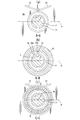
- FIG. 2 is an enlarged cross-sectional view of a part of the front head of the compressor shown in FIG. 3A is a cross-sectional view taken along the line AA in FIG. 2
- FIG. 3B is a cross-sectional view taken along the line BB in FIG. 2
- FIG. 3 is a cross-sectional view taken along the line CC of FIG. 4A and 4B are diagrams for explaining the flow of oil into the seal space and the oil storage state.
- FIG. 4A is a cross-sectional view taken along the line BB in FIG. 2, and FIG. It is sectional drawing to which some front heads of the compressor of this were expanded.
- FIG. 4A is a cross-sectional view taken along the line BB in FIG. 2, and FIG. It is sectional drawing to which some front heads of the compressor of this were expanded.
- FIG. 4A is a cross-sectional view taken along the line BB
- FIG. 5 is a view showing another example of the oil discharge passage, (a) is a cross-sectional view corresponding to a cut portion taken along the line BB of FIG. 2, and (b) is a cross-sectional view of FIG. It is sectional drawing corresponding to the cut part of C line.
- FIG. 6 is a sectional view showing another compressor according to the embodiment of the present invention.
- FIG. 1 shows a variable capacity swash plate compressor used in a refrigeration cycle as an example of a compressor.
- This compressor includes a cylinder block 1, a rear head 3 assembled on the rear side (right side in the figure) of the cylinder block 1 via a valve plate 2, and a front side (left side in the figure) of the cylinder block 1. And a front head 4 assembled so as to be closed.
- the front head 4, the cylinder block 1, the valve plate 2, and the rear head 3 are fastened in the axial direction by fastening bolts 5 and constitute a housing for the entire compressor.
- a crankshaft 6 provided by the front head 4 and the cylinder block 1 accommodates a drive shaft 7 having one end protruding from the front head 4.
- a drive pulley (not shown) connected to the engine of the vehicle via a belt is fixed to a portion of the drive shaft 7 protruding from the front head 4.
- one end side of the drive shaft 7 is hermetically sealed with the front head 4 via a shaft sealing member 10 provided between the drive shaft 7 and the refrigerant leakage along the drive shaft 7 is prevented.
- One end side of the drive shaft 7 is rotatably supported by a radial bearing 11 accommodated on the crank chamber side of the shaft seal member 10 of the front head 4, and the other end side of the drive shaft 7 is supported by the cylinder block 1. Is rotatably supported by a radial bearing 12 housed in the housing.
- the cylinder block 1 is formed with a support hole 13 in which the radial bearing 12 is accommodated, and a plurality of cylinder bores 15 arranged at equal intervals on a circumference around the support hole 13.
- a single-head piston 16 is inserted into the cylinder bore 15 so as to be slidable back and forth.
- the one-head piston 16 is formed by joining a head portion 16a inserted into the cylinder bore 15 and an engaging portion 16b protruding into the crank chamber 6 in the axial direction.
- a thrust flange 17 that rotates integrally with the drive shaft 7 is fixed to the drive shaft 7 in the crank chamber 6.
- the thrust flange 17 is rotatably supported via an annular thrust bearing 18 with respect to the inner wall surface 4 a of the front head 4 formed substantially perpendicular to the drive shaft 7.
- the thrust flange 17 constitutes a power transmission member, and the thrust flange 17 is connected to a swash plate 20 via a link mechanism 19.
- the swash plate 20 is attached so as to be able to tilt around a hinge ball 21 slidably provided on the drive shaft 7, and is integrated with the rotation of the thrust flange 17 via the link mechanism 19. It is designed to rotate. And the engaging part 16b of the single-headed piston 16 is moored to the peripheral part of the swash plate 20 via a pair of shoes 22 arranged at the front and back.
- Reference numeral 24 denotes a suction hole formed in the valve plate 2 that communicates the suction chamber 25 formed in the rear head 3 and the compression chamber 23 via a suction valve (not shown), and 26 denotes a hole formed in the rear head 3. This is a discharge hole formed in the valve plate 2 that communicates the discharge chamber 27 and the compression chamber 23 via a discharge valve (not shown).
- Reference numeral 28 denotes a pressure control valve that controls the communication state between the discharge chamber 27 and the crank chamber 6 and adjusts the crank chamber pressure to adjust the tilt angle of the swash plate 20.
- the shaft seal member 10 and the radial bearing 11 are disposed with a space therebetween in the axial direction, and a shaft seal is provided between the inner surface of the front head 4 and the outer peripheral surface of the drive shaft 7.
- An annular seal space 30 defined by the member 10 and the radial bearing 11 is formed. That is, the seal space 30 is defined by being surrounded by the radial bearing 11, the shaft sealing member 10, the inner surface of the boss portion 41 of the front head 4, and the outer peripheral surface of the drive shaft 7.
- the inner surface of the boss portion 41 of the front head 4 that defines the seal space 30 includes a conical surface 30a whose inner diameter gradually increases from the radial bearing 11 toward the shaft sealing member 10, and a cylindrical surface 30b that follows the conical surface 30a. ing.
- the front head 4 also has a bearing surface for receiving the thrust bearing 18 on the inner wall surface 4a located above the drive shaft 7, more specifically, the thrust bearing 18 is held by the needle roller 18a and this as shown.
- a guide groove 31 for guiding oil is formed on the surface of the front head 4 that receives the thrust trace 18b.
- the guide groove is formed by a pair of grooves extending obliquely on the inner surface of the front head 4 toward an oil supply passage 32 (described later) formed in the front head 4.
- the oil that is formed and scraped up by the swash plate in the crank chamber and flows down along the inner surface of the front head is widely received and concentrated toward the oil supply passage.
- the guide groove 31 and the seal space 30 are connected by an oil supply passage 32 formed in the front head 4 at a predetermined angle with respect to the axis of the drive shaft 7.
- the oil introduced into the guide groove 31 is supplied to the seal space 30.
- the thrust flange 17 is opposed to the inner wall surface 4a of the front head 4 while being separated via a thrust bearing 18, and a gap 33 is formed between the thrust flange 17 and the inner wall surface 4a of the front head 4.
- the gap 33 between the thrust flange 17 and the inner wall surface 4 a is closed by the thrust trace 18 b of the thrust bearing 18. Therefore, the oil descending through the guide groove 31 does not flow into the gap 33 (inside the thrust bearing 18) between the thrust flange 17 and the inner wall surface 4a of the front head 4, and most of the oil is supplied. It is introduced into the passage 32.
- the outlet 32a of the oil supply passage 32 is connected to the seal space 30 only at the conical surface 30a, and is opened at a position where the introduced oil does not directly hit the shaft seal member 10. That is, the conical surface 30a is not located at a position overlapping the shaft seal member 10 in the axial direction, and is formed so as to be shifted to a portion closer to the radial bearing 11 than the shaft seal member 10 by a predetermined dimension.
- the front head 4 further has an oil discharge passage 34 having one end communicating with the seal space 30 and the other end communicating with the crank chamber 6 (in this example, the gap 33 communicating with the crank chamber 6).
- the oil discharge passage 34 is formed substantially parallel to the drive shaft 7, and a part or all of the inflow port 34 a (one end of the oil discharge passage 34) that opens into the seal space 30 is on the conical surface 30 a.
- all of the inflow ports 34a are formed so as to open at the conical surface 30a).
- the opening is opened at a position above the horizontal plane ⁇ including the axis O of the drive shaft 7.
- the area of the inlet 34 a that opens to the seal space 30 of the oil discharge passage 34 is formed smaller than the area of the outlet 32 a that opens to the seal space of the oil supply passage 32.
- the inlet 34a of the oil discharge passage 34 has a drive shaft more than the position of the outlet 32a that opens into the seal space 30 of the oil supply passage 32 as a reference. 7 is opened to the rear side in the rotation direction (direction indicated by an arrow in the figure).
- the other end of the oil discharge passage 34 opens to the inner wall surface 4a of the front head 4 on the inner side of the thrust bearing 18 (on the drive shaft side than the thrust bearing 18).
- the thrust bearing 18 is guided to the gap 33 between the thrust flange on the inner side of the thrust bearing 18 and the inner wall surface 4a of the front head 4, and then guided to the sliding portion (radial bearing 11) inside the thrust bearing 18 and It is made to return to the crank chamber 6 through a gap.
- the inner peripheral surface of the seal space 30 is formed as a conical surface 30 a that expands toward the shaft seal member 10, the oil guided to the seal space 30 is around the drive shaft 7 before the shaft seal member 10. Or, it is guided to the lower side of the drive shaft 7 along the inner surface of the boss portion 41 of the front head 4, and then guided to the shaft seal member 10 along the conical surface 30 a.
- the oil discharge passage 34 opens in the seal space at a position above the horizontal plane including the axis O of the drive shaft 7, the oil stored in the seal space 30 as shown in FIG. 4. Until the height of the inlet 34a of the oil discharge passage 34 is raised or the oil level does not reach the inlet 34a, the oil in the seal space 30 is not discharged. Accordingly, even when the crank chamber oil is deficient during high-speed rotation, the oil stored in the seal space 30 is not easily discharged from the seal space 30 and can be held in the seal space.
- the oil flowing down through the guide groove is not directly guided to the inner side of the thrust bearing 18 (the gap 33 between the thrust flange 17 and the inner wall surface 4a of the front head 4), but first through the oil supply passage 32. Then, it is guided to the seal space 30 and then guided to the inside of the thrust bearing 18 (the gap 33 between the thrust flange 17 and the inner wall surface 4 a of the front head 4) through the oil discharge passage 34. As described above, the oil is not supplied in parallel to the seal space 30 and the inside of the thrust bearing 18 (the gap 33 between the thrust flange 17 and the inner wall surface 4a of the front head 4).
- the area of the inlet 34a of the oil discharge passage 34 is smaller than the area of the outlet 32a that opens to the seal space 30 of the oil supply passage 32. This makes it possible to increase the discharge resistance of the oil and facilitate the retention of the oil in the seal space.
- the inlet 34a of the oil discharge passage 34 is opened to the rear side in the rotational direction of the drive shaft 7 from the position of the outlet 32a where the oil supply passage 32 opens into the seal space 30, the oil is supplied In addition to the effect of making it difficult to discharge, the oil introduced into the seal space 30 from the oil supply passage 32 can be prevented from flowing out through the oil discharge passage 34 without contributing to lubrication or cooling of the shaft seal member 10. It becomes possible.
- the present invention is not limited to this, and a plurality of them may be provided as appropriate.
- the inlet 34 a that opens to the seal space 30 of each oil discharge passage 34 is formed from a horizontal plane ⁇ including the axis of the drive shaft 7.
- the outlet opening that opens to the upper position and opens to the crank chamber side may be opened to a position inside the thrust bearing 18.
- the sum of the areas of the inlets 34 a of the respective oil discharge passages 34 that open to the seal space 30 is smaller than the area of the outlet 32 a that opens to the seal space 30 of the oil supply passage 32. In this case, it is possible to achieve the same effects as the above configuration example.
- the seal space 30 is also provided in the compressor including the oil discharge mechanism 50 that actively discharges the oil in the crank chamber 6 to the suction chamber 25. It is possible to avoid the inconvenience that the oil in the seal space is depleted while ensuring the flow of the oil, and it is possible to ensure good lubrication of the shaft seal member 10.
Landscapes
- Engineering & Computer Science (AREA)
- Mechanical Engineering (AREA)
- General Engineering & Computer Science (AREA)
- Compressors, Vaccum Pumps And Other Relevant Systems (AREA)
- Compressor (AREA)
Abstract
高速回転時においてクランク室内のオイルが欠乏する運転時においても、シール空間のオイルの流動を確保しつつ、シール空間のオイル不足を回避して軸封部材の良好な潤滑を確保することが可能な圧縮機を提供する。一端がクランク室(6)に連通し、他端がラジアル軸受(11)と軸封部材(10)との間に形成されたシール空間(30)に連通するオイル供給通路(32)と、一端がシール空間(30)に連通し、他端がクランク室(6)に連通するオイル排出通路(34)と、がハウジングに形成された圧縮機において、オイル排出通路(34)のシール空間に開口する流入口(34a)を、駆動軸(7)の軸心を含む水平面よりも上側の位置に開口させる。
Description
本発明は、車両用空調装置などに用いられる圧縮機に関し、駆動軸の周囲に設けられてハウジングとの間を封止する軸封部材に供給されるオイル(潤滑油)の経路構造を改善した圧縮機に関し、特に、クランク室内のオイル量が少なくなりやすい運転条件時やクランク室内のオイルを積極的に吸入室へ排出している機種において軸封部材へのオイルの供給量を確保できるようにした経路構造を有する圧縮機に関する。
クランク室を貫通してハウジングに回転自在に支持された駆動軸と、クランク室に配されて前記駆動軸の回転に同期して回転し、スラスト軸受を介してハウジングの内壁面に回転可能に支持された動力伝達部材と、動力伝達部材の回転に伴い、ハウジングに形成されたシリンダボア内でピストンを往復摺動させる駆動手段とを具備する圧縮機にあっては、ハウジングと駆動軸との間に、駆動軸を受けるラジアル軸受やクランク室内の流体漏洩を防止する軸封部材が配置されている。このような圧縮機においては、駆動軸と軸封部材との摺接部分での焼き付きを防止するために、良好な潤滑が要請されている。
そこで、従来においては、ラジアル軸受と軸封部材との間に区画形成されたシール空間にオイルを供給すると共にこのシール空間内のオイルの流動を確保するための種々の構成が提案されている。
例えば、特開2002-310067号公報(特許文献1)においては、クランク室とシール空間とをハウジングに設けたオイル供給通路を介して連通させると共に、シール空間とクランク室とを、駆動軸と滑り軸受との間に形成した隙間を介して連通させた構成が提案されている。また、特開2005-23849号公報(特許文献2)においては、クランク室とシール空間とをハウジングに設けたオイル供給通路を介して連通させると共に、シール空間とクランク室とを、ラジアル軸受を受ける軸受面とラジアル軸受との間に形成したオイル排出通路を介して連通させた構成が提案されている。
例えば、特開2002-310067号公報(特許文献1)においては、クランク室とシール空間とをハウジングに設けたオイル供給通路を介して連通させると共に、シール空間とクランク室とを、駆動軸と滑り軸受との間に形成した隙間を介して連通させた構成が提案されている。また、特開2005-23849号公報(特許文献2)においては、クランク室とシール空間とをハウジングに設けたオイル供給通路を介して連通させると共に、シール空間とクランク室とを、ラジアル軸受を受ける軸受面とラジアル軸受との間に形成したオイル排出通路を介して連通させた構成が提案されている。
しかしながら、上述したいずれの構成においても、駆動軸よりも下方となる部分でシール空間とクランク室とを連通させる状態が形成されるので、オイル供給通路を介してシール空間に導入されるオイル量が少なくなる場合には、シール空間のオイルが必要以上に排出されて欠乏することが想定され、シール空間にオイルが十分に保留されず、駆動軸と軸封部材との摺接部分に焼き付きが生じる不都合が懸念される。
そこで、オイル排出通路のシール空間に開口する流入口を、駆動軸の軸封部材と接触する最も低い位置よりも上側であり、且つ、駆動軸の軸心を含む水平面と同位置かそれよりも下側の位置に開口させることで、シール空間のオイルを適正量に保持してオイル不足を回避して良好な潤滑を確保すると共に、軸封部材に供給されるオイルの入れ替わりを促進することで、軸封部材の温度上昇による軸封機能の低下(オイル漏れ)を抑制するようにした圧縮機が提案されている(特許文献3参照)。
しかしながら、昨今においては、圧縮機に対する市場要求として、高速回転時での耐力が要求されている。一般的に、高速回転時においては、高熱負荷時でない限り、冷房能力が過剰になることを抑制するために、クランク室の圧力を高めてピストンストロークをデストロークする制御が行われる。このような高速回転時においてクランク室圧が吸入室圧よりも大きくなる運転条件下においては、クランク室には、限られたオイルしか溜められず、シール空間へ供給されるオイル量が不足し、軸封部材の潤滑と冷却が不十分となる。
この点、上述した特許文献3においては、オイル排出通路のシール空間に開口する流入口が、駆動軸の軸心を含む水平面と同位置かそれよりも下側の位置に開口しているので、シール空間のオイルを適正量に保持してオイル不足を回避しつつ、軸封部材に供給されるオイルの入れ替わりを促進する効果を期待することができる。しかしながら、高速回転時においてクランク室内のオイルが欠乏する上述した運転条件下(高速回転時において、クランク室圧が吸入室圧より大きくなる条件下)においては、オイル供給通路を介してシール空間に導入されるオイル量が少なくなるので、シール空間に溜められているオイルが駆動軸の回転によって掻き上げられる等してオイル排出通路を介してクランク室へ排出される分をシール空間に導入されるオイル量で賄うことができなくなる。このため、シール空間に潤沢なオイルが保持されにくくなり、軸封部材の潤滑が損なわれると共に、オイルの流動が少なくなるため、軸封部材の冷却効果も不十分になることが懸念される。
このような懸念は、特に、クランク室のオイルを積極的に吸入室に排出するオイル排出機構を具備している、例えば、特許文献4で示されるような圧縮機においては、一層深刻なものとなる。
したがって、高速回転時においてクランク室内のオイルが欠乏する過酷な運転時においても軸封部材の潤滑と冷却を確保できるようにするためには、オイルの経路構造をさらに見直す必要がある。
本発明は、係る事情に鑑みてなされたものであり、高速回転時においてクランク室内のオイルが欠乏する運転時においても、シール空間のオイルの流動を確保しつつ、シール空間のオイル不足を回避して軸封部材の良好な潤滑を維持することが可能な圧縮機を提供することを主たる課題としている。
上記課題を達成するために、本発明に係る圧縮機は、クランク室を画成するハウジングと、前記クランク室を貫通して前記ハウジングにラジアル軸受を介して回転自在に支持され、一端部が前記ハウジングから突出する駆動軸と、前記駆動軸の前記ラジアル軸受よりも一端部側に配置され、前記駆動軸と前記ハウジングとの間を封止する軸封部材と、前記ハウジングに形成され、一端が前記クランク室に連通し、他端が前記ラジアル軸受と前記軸封部材との間に形成されたシール空間に連通するオイル供給通路と、一端が前記シール空間に連通し、他端が前記クランク室に連通するオイル排出通路と、を備えた圧縮機であって、前記オイル排出通路の前記シール空間に開口する流入口は、前記駆動軸の軸心を含む水平面よりも上側の位置に開口していることを特徴としている。
したがって、オイル排出通路の前記シール空間に開口する流入口を駆動軸の軸心を含む水平面よりも上側の位置に開口したので、シール空間内のオイルが高速回転時に掻き上げられる等してオイル排出通路からクランク室へ流出しても、シール空間内のオイルを十分に残すことが可能となる。このため、クランク室内のオイルが欠乏してオイル供給通路からシール空間に導入されるオイルが少なくなっても、シール空間内のオイルを潤沢に保持することができ、軸封部材の良好な潤滑を維持することが可能となる。また、オイル排出通路は、駆動軸の軸心を含む水平面より上側の位置でシール空間に開口しているものの、シール空間内のオイルをクランク室へ送出可能な構成となっているので、シール空間内のオイルの流動を妨げるものではない。
なお、シール空間内のオイルを保持しやすくするために、前記オイル排出通路の前記流入口の面積を、前記オイル供給通路の前記シール空間に開口する流出口の面積よりも小さくするとよい。ここで、オイル排出通路が複数設けられる場合には、シール空間に開口するそれぞれのオイル排出通路の流入口の面積の総和がオイル供給通路の前記シール空間に開口する流出口の面積よりも小さくなるようにするとよい。
また、オイル供給通路からシール空間に導入されたオイルが軸封部材の潤滑や冷却に寄与することなくオイル排出通路からクランク室へ流出する不都合を抑えるために、前記オイル排出通路の前記流入口は、前記オイル供給通路の前記シール空間に開口する流出口の位置よりも前記駆動軸の回転方向の後方側に開口されることが望ましい。
さらに、駆動軸の回転に伴って回転する動力伝達部材がハウジングの内面に環状のスラスト軸受を介して支持されている圧縮機においては、前記クランク室内のオイルを、スラスト軸受の内側に導くことなくオイル供給通路を介してシール空間に一旦導き(オイルの一部がオイル供給通路をバイパスすることによってシール空間に導かれるオイル量が減少する不都合を回避し)、しかる後にオイル排出通路を介してスラスト軸受の内側に導く構成にするとよい。
このような構成を採用すれば、ハウジングの内面を伝ってオイル供給通路へ導かれるオイルを、シール空間に供給した後にオイル排出通路を介してスラスト軸受の内側に導く直列のオイル供給経路が形成されるので、軸封部材と共にスラスト軸受の内側の摺動部分(ラジアル軸受等)にも潤沢なオイルを供給することが可能となる。
また、以上のような構成を採用した場合には、クランク室に貯溜されるオイルを排出するためのオイル排出機構が設けられている圧縮機においても、シール空間のオイルの流動を確保しつつ、シール空間内のオイル不足を回避して軸封部材の良好な潤滑を確保することが可能となる。
以上述べたように、本発明によれば、一端がクランク室に連通し、他端がラジアル軸受と軸封部材との間に形成されたシール空間に連通するオイル供給通路と、一端がシール空間に連通し、他端がクランク室に連通するオイル排出通路と、をハウジングに備えた圧縮機において、オイル排出通路のシール空間に開口する流入口を、駆動軸の軸心を含む水平面よりも上側の位置に開口するようにしたので、高速回転時においてクランク室内のオイルが欠乏する運転時においても、シール空間のオイルの流動を確保しつつ、シール空間のオイル不足を回避して軸封部材の良好な潤滑を確保することが可能となる。
ここで、オイル排出通路の流入口の面積を、オイル供給通路のシール空間に開口する流出口の面積よりも小さくすることで、シール空間内にオイルを保持しやすくなり、シール空間内のオイル不足を一層回避することが可能となる。また、オイル排出通路の流入口を、オイル供給通路のシール空間に開口する流出口の位置よりも駆動軸の回転方向の後方側に開口させることで、オイル供給通路からシール空間に導入されたオイルが軸封部材の潤滑や冷却に寄与することなくオイル排出通路からクランク室へ流出してしまう不都合を抑えることが可能となる。
さらに、駆動軸の回転に伴って回転する動力伝達部材がハウジングの内面に環状のスラスト軸受を介して支持されている圧縮機においては、クランク室内のオイルを、スラスト軸受の内側に導くことなくオイル供給通路を介して前記シール空間へ導き、しかる後にオイル排出通路を介してスラスト軸受の内側に導くようにすることで、軸封部材のみならずスラスト軸受の内側の摺動部分にも潤沢なオイルを供給することができ、両者において良好な潤滑を確保することが可能となる。
以下、この発明の実施の態様を図面に基づいて説明する。
図1において、圧縮機の一例として冷凍サイクルに用いられる可変容量型斜板式圧縮機が示されている。この圧縮機は、シリンダブロック1と、このシリンダブロック1のリア側(図中、右側)にバルブプレート2を介して組み付けられたリアヘッド3と、シリンダブロック1のフロント側(図中、左側)を閉塞するように組み付けられたフロントヘッド4とを有して構成されている。これらフロントヘッド4、シリンダブロック1、バルブプレート2、及び、リアヘッド3は、締結ボルト5により軸方向に締結されており、圧縮機全体のハウジングを構成している。
図1において、圧縮機の一例として冷凍サイクルに用いられる可変容量型斜板式圧縮機が示されている。この圧縮機は、シリンダブロック1と、このシリンダブロック1のリア側(図中、右側)にバルブプレート2を介して組み付けられたリアヘッド3と、シリンダブロック1のフロント側(図中、左側)を閉塞するように組み付けられたフロントヘッド4とを有して構成されている。これらフロントヘッド4、シリンダブロック1、バルブプレート2、及び、リアヘッド3は、締結ボルト5により軸方向に締結されており、圧縮機全体のハウジングを構成している。
フロントヘッド4とシリンダブロック1とによって画設されるクランク室6には、一端がフロントヘッド4から突出する駆動軸7が収容されている。この駆動軸7のフロントヘッド4から突出した部分には、車両のエンジンにベルトを介して連結される図示しない駆動プーリが固定される。また、この駆動軸7の一端側は、フロントヘッド4との間に設けられた軸封部材10を介してフロントヘッド4との間が気密よく封じられ、駆動軸7に沿った冷媒漏洩を防止するようにしている。そして、駆動軸7の一端側は、フロントヘッド4の軸封部材10よりもクランク室側に収容されたラジアル軸受11にて回転自在に支持され、駆動軸7の他端側は、シリンダブロック1に収容されたラジアル軸受12にて回転自在に支持されている。
シリンダブロック1には、前記ラジアル軸受12が収容される支持孔13と、この支持孔13を中心とする円周上に等間隔に配された複数のシリンダボア15とが形成されており、それぞれのシリンダボア15には、片頭ピストン16が往復摺動可能に挿入されている。この片頭ピストン16は、シリンダボア15内に挿入される頭部16aと、クランク室6に突出する係合部16bとを軸方向に接合して形成されている。
前記駆動軸7には、クランク室6内において、該駆動軸7と一体に回転するスラストフランジ17が固定されている。このスラストフランジ17は、駆動軸7に対して略垂直に形成されたフロントヘッド4の内壁面4aに対して環状のスラスト軸受18を介して回転自在に支持されている。このスラストフランジ17によって動力伝達部材が構成されており、このスラストフランジ17は、リンク機構19を介して斜板20が連結されている。
斜板20は、駆動軸7上に摺動自在に設けられたヒンジボール21を中心に傾動可能に取り付けられているもので、リンク機構19を介してスラストフランジ17の回転に同期して一体に回転するようになっている。そして、斜板20の周縁部には、前後に配された一対のシュー22を介して片頭ピストン16の前記係合部16bが係留されている。
したがって、駆動軸7が回転すると、これに伴って斜板20が回転し、この斜板20の回転運動がシュー22を介して片頭ピストン16の往復直線運動に変換され、シリンダボア内において片頭ピストン16とバルブプレート2との間に形成される圧縮室23の容積が変更されるようになっている。
尚、24は、リアヘッド3に形成された吸入室25と圧縮室23とを図示しない吸入弁を介して連通するバルブプレート2に形成された吸入孔であり、26は、リアヘッド3に形成された吐出室27と圧縮室23とを図示しない吐出弁を介して連通するバルブプレート2に形成された吐出孔である。また、28は、吐出室27とクランク室6との連通状態を制御し、クランク室圧を調整して斜板20の傾動角度を調節する圧力制御弁である。
ところで、図2にも示されるように、前記軸封部材10とラジアル軸受11は軸方向に間隔を開けて配設され、フロントヘッド4の内面と駆動軸7の外周面との間で軸封部材10とラジアル軸受11とによって区画形成された環状のシール空間30が形成されている。
すなわち、シール空間30は、ラジアル軸受11と、軸封部材10と、フロントヘッド4のボス部41の内面と、駆動軸7の外周面とによって囲まれて画成されているもので、この例では、シール空間30を画成するフロントヘッド4のボス部41の内面は、ラジアル軸受11から軸封部材10に向かって徐々に内径が大きくなる円錐面30aとこれに続く円筒面30bとを備えている。
すなわち、シール空間30は、ラジアル軸受11と、軸封部材10と、フロントヘッド4のボス部41の内面と、駆動軸7の外周面とによって囲まれて画成されているもので、この例では、シール空間30を画成するフロントヘッド4のボス部41の内面は、ラジアル軸受11から軸封部材10に向かって徐々に内径が大きくなる円錐面30aとこれに続く円筒面30bとを備えている。
また、フロントヘッド4には、駆動軸7の上方に位置する内壁面4aのスラスト軸受18を受ける軸受面、より具体的には、図示するようにスラスト軸受18をニードルローラ18aとこれを保持する環状のスラストレース18bとによって構成する場合には、フロントヘッド4のスラストレース18bを受ける面にかけてオイルを導く案内溝31が形成されている。
この案内溝は、図3(a)に示されるように、フロントヘッド4に穿設された後述するオイル供給通路32に向かってフロントヘッド4の内面に斜めに延設された対をなす溝によって形成され、クランク室内で斜板によって掻き上げられてフロントヘッドの内面を伝って流下するオイルを幅広く受け止め、オイル供給通路に向かって集約させる機能を有している。
そして、案内溝31とシール空間30とは、駆動軸7の軸線に対して所定の角度でフロントヘッド4に穿設されたオイル供給通路32によって接続されており、このオイル供給通路32を介して、案内溝31に導入されたオイルをシール空間30へ供給するようにしている。
前記スラストフランジ17は、フロントヘッド4の内壁面4aに対して、スラスト軸受18を介して離した状態で対向配置され、フロントヘッド4の内壁面4aとの間に間隙33が形成されている。そして、この例においては、スラストフランジ17と内壁面4aとの間隙33をスラスト軸受18のスラストレース18bによって閉塞している。このため、案内溝31を伝って降下するオイルは、スラストフランジ17とフロントヘッド4の内壁面4aとの間の間隙33(スラスト軸受18の内側)には流入されず、その大部分がオイル供給通路32に導入されるようになっている。
また、オイル供給通路32の流出口32aは、前記円錐面30aの部分のみでシール空間30に接続されており、また、軸封部材10に導入オイルが直接当たらない位置に開口している。すなわち、円錐面30aは、軸封部材10とは軸方向で重なり合う位置にはなく、軸封部材10よりも所定寸法だけラジアル軸受11寄りの部位にずらして形成されている。
フロントヘッド4には、一端がシール空間30に連通し、他端がクランク室6(この例では、クランク室6に通じる前記間隙33)に連通するオイル排出通路34がさらに形成されている。この例において、オイル排出通路34は、駆動軸7と略平行に形成され、シール空間30に開口する流入口34a(オイル排出通路34の一端)は、一部又は全部が前記円錐面30aにかかるように開口している(図1の例では、流入口34aの全部が円錐面30aで開口するように形成されており)。また、図3(b)に示されるように、駆動軸7の軸心Oを含む水平面αよりも上側となる位置に開口している。
ここで、オイル排出通路34のシール空間30に開口する流入口34aの面積は、オイル供給通路32のシール空間に開口する流出口32aの面積よりも小さく形成されている。また、図3(b)に示されるように、オイル排出通路34の流入口34aは、オイル供給通路32の前記シール空間30に開口する流出口32aの位置を基準として、その位置よりも駆動軸7の回転方向(図中において矢印で示す方向)の後方側に開口している。
そして、オイル排出通路34の他端は、スラスト軸受18の内側(スラスト軸受18よりも駆動軸側)においてフロントヘッド4の内壁面4aに開口しており、このオイル排出通路34から流出したオイルを、スラスト軸受18の内側となるスラストフランジとフロントヘッド4の内壁面4aとの間の間隙33に導き、その後、スラスト軸受18の内側の摺動部分(ラジアル軸受11)に導くと共にスラスト軸受18の隙間を介してクランク室6に戻すようにしている。
以上の構成において、フロントヘッド4の内壁面に付着されたオイルが第1の案内溝31を伝って下方へ流下すると、このオイルは、オイル供給通路32をバイパスしてスラスト軸受18の内側に導かれることはなく、その殆ど全てがオイル供給通路32を介してシール空間30へ導かれる。
シール空間30の内周面は、軸封部材10に向かって拡がる円錐面30aに形成されているので、シール空間30に導かれたオイルは、軸封部材10の手前において、駆動軸7の周囲やフロントヘッド4のボス部41の内面を伝って駆動軸7の下側に導かれ、その後、円錐面30aを伝って軸封部材10へ導かれる。
また、オイル排出通路34は、駆動軸7の軸心Oを含む水平面よりも上側となる位置でシール空間に開口しているので、図4に示されるように、シール空間30に溜められたオイルがオイル排出通路34の流入口34aの高さまで掻き上げられるか、オイルの液位が流入口34aに達しない限り、シール空間30内のオイルは排出されることはない。
したがって、高速回転時においてクランク室内のオイルが欠乏する運転時においても、シール空間30に溜められたオイルはこのシール空間30から排出されにくくなり、シール空間に保持させることが可能となる。
したがって、高速回転時においてクランク室内のオイルが欠乏する運転時においても、シール空間30に溜められたオイルはこのシール空間30から排出されにくくなり、シール空間に保持させることが可能となる。
しかも、案内溝を伝って流下するオイルは、スラスト軸受18の内側(スラストフランジ17とフロントヘッド4の内壁面4aとの間の間隙33)に直接導かれることなく、先ずオイル供給通路32を介してシール空間30へ導かれ、しかる後に、オイル排出通路34を介してスラスト軸受18の内側(スラストフランジ17とフロントヘッド4の内壁面4aとの間の間隙33)に導かれる。このように、オイルは、シール空間30とスラスト軸受18の内側(スラストフランジ17とフロントヘッド4の内壁面4aとの間の間隙33)にパラレルに供給されるのではなく、シール空間30と間隙33に直列的に流れるので、クランク室6からオイル供給通路32を介してシール空間30に導かれるオイルが少ない場合でも、シール空間30や間隙33に対して潤沢なオイルを供給することが可能となる。このため、軸封部材10やスラスト軸受18の内側の摺動部分の良好な潤滑を確保することが可能となる。また、オイルを直列的に流すことで、シール空間内のオイルの流動を促進することができるので、軸封部材1の冷却効果を高めることが可能となる。
さらに、上述の構成においては、オイル排出通路34の流入口34aの面積を、オイル供給通路32のシール空間30に開口する流出口32aの面積よりも小さくしているので、シール空間30からのオイルの排出抵抗を大きくしてシール空間内にオイルを保持しやすくすることが可能となる。
さらにまた、オイル排出通路34の流入口34aを、オイル供給通路32がシール空間30に開口する流出口32aの位置よりも駆動軸7の回転方向後方側に開口させるようにしているので、オイルを排出しにくくする効果に加えて、オイル供給通路32からシール空間30に導入されたオイルが軸封部材10の潤滑や冷却に寄与することなくオイル排出通路34を介して流出する不都合を抑えることが可能となる。
なお、以上の構成例においては、オイル供給通路32やオイル排出通路34を1つずつ設けた例を示したが、これに限定されるものではなく、適宜複数設けるようにしてもよい。例えば、オイル排出通路34を複数設ける場合には、図5に示されるように、それぞれのオイル排出通路34のシール空間30に開口する流入口34aを、駆動軸7の軸心を含む水平面αよりも上側の位置に開口し、クランク室側に開口する流出口を、スラスト軸受18の内側の位置に開口させるとよい。
このような構成においては、シール空間30に開口するそれぞれのオイル排出通路34の流入口34aの面積の総和がオイル供給通路32のシール空間30に開口する流出口32aの面積よりも小さくなるようにするとよく、これにより、前記構成例と同様の作用効果を奏することが可能となる。
このような構成においては、シール空間30に開口するそれぞれのオイル排出通路34の流入口34aの面積の総和がオイル供給通路32のシール空間30に開口する流出口32aの面積よりも小さくなるようにするとよく、これにより、前記構成例と同様の作用効果を奏することが可能となる。
また、上述の構成を採用すれば、図6に示されるように、クランク室6のオイルを積極的に吸入室25に排出するオイル排出機構50を具備している圧縮機においても、シール空間30のオイルの流動を確保しつつ、シール空間内のオイルが枯渇する不都合を避けることが可能となり、軸封部材10の良好な潤滑を確保することが可能となる。
4 フロントヘッド
6 クランク室
7 駆動軸
10 軸封部材
11,12 ラジアル軸受
30 シール空間
32 オイル供給通路
32a 流出口
33 間隙
34 オイル排出通路
34a 流入口
50 オイル排出機構
α 駆動軸の軸心を含む水平面
6 クランク室
7 駆動軸
10 軸封部材
11,12 ラジアル軸受
30 シール空間
32 オイル供給通路
32a 流出口
33 間隙
34 オイル排出通路
34a 流入口
50 オイル排出機構
α 駆動軸の軸心を含む水平面
Claims (5)
- クランク室を画成するハウジングと、
前記クランク室を貫通して前記ハウジングにラジアル軸受を介して回転自在に支持され、一端部が前記ハウジングから突出する駆動軸と、
前記駆動軸の前記ラジアル軸受よりも一端部側に配置され、前記駆動軸と前記ハウジングとの間を封止する軸封部材と、
前記ハウジングに形成され、一端が前記クランク室に連通し、他端が前記ラジアル軸受と前記軸封部材との間に形成されたシール空間に連通するオイル供給通路と、
一端が前記シール空間に連通し、他端が前記クランク室に連通するオイル排出通路と、
を備えた圧縮機において、
前記オイル排出通路の前記シール空間に開口する流入口は、前記駆動軸の軸心を含む水平面よりも上側の位置に開口していることを特徴とする圧縮機。 - 前記オイル排出通路の前記流入口の面積は、前記オイル供給通路の前記シール空間に開口する流出口の面積よりも小さいことを特徴とする請求項1記載の圧縮機。
- 前記オイル排出通路の前記流入口は、前記オイル供給通路の前記シール空間に開口する流出口の位置よりも前記駆動軸の回転方向の後方側に開口していることを特徴とする請求項1又は2記載の圧縮機。
- 前記駆動軸の回転に伴って回転する動力伝達部材が前記ハウジングの内面に環状のスラスト軸受を介して支持され、前記クランク室内のオイルは、前記スラスト軸受の内側に導かれることなく前記オイル供給通路を介して前記シール空間に導かれ、しかる後に前記オイル排出通路を介して前記スラスト軸受の内側に導かれることを特徴とする請求項1乃至3のいずれかに記載の圧縮機。
- 前記クランク室には、ここに貯溜されるオイルを排出するためのオイル排出機構が設けられていることを特徴とする請求項1乃至4のいずれかに記載の圧縮機。
Applications Claiming Priority (2)
| Application Number | Priority Date | Filing Date | Title |
|---|---|---|---|
| JP2017094382 | 2017-05-11 | ||
| JP2017-094382 | 2017-05-11 |
Publications (1)
| Publication Number | Publication Date |
|---|---|
| WO2018207724A1 true WO2018207724A1 (ja) | 2018-11-15 |
Family
ID=64104720
Family Applications (1)
| Application Number | Title | Priority Date | Filing Date |
|---|---|---|---|
| PCT/JP2018/017607 Ceased WO2018207724A1 (ja) | 2017-05-11 | 2018-05-07 | 圧縮機 |
Country Status (1)
| Country | Link |
|---|---|
| WO (1) | WO2018207724A1 (ja) |
Cited By (1)
| Publication number | Priority date | Publication date | Assignee | Title |
|---|---|---|---|---|
| WO2020162101A1 (ja) * | 2019-02-06 | 2020-08-13 | サンデン・オートモーティブコンポーネント株式会社 | 圧縮機 |
Citations (4)
| Publication number | Priority date | Publication date | Assignee | Title |
|---|---|---|---|---|
| JPS5096213U (ja) * | 1973-12-29 | 1975-08-12 | ||
| JPS6143555B2 (ja) * | 1979-06-22 | 1986-09-27 | Sanden Corp | |
| JPH0444481U (ja) * | 1990-08-17 | 1992-04-15 | ||
| JPH11117866A (ja) * | 1997-10-09 | 1999-04-27 | Sanden Corp | 圧縮機 |
-
2018
- 2018-05-07 WO PCT/JP2018/017607 patent/WO2018207724A1/ja not_active Ceased
Patent Citations (4)
| Publication number | Priority date | Publication date | Assignee | Title |
|---|---|---|---|---|
| JPS5096213U (ja) * | 1973-12-29 | 1975-08-12 | ||
| JPS6143555B2 (ja) * | 1979-06-22 | 1986-09-27 | Sanden Corp | |
| JPH0444481U (ja) * | 1990-08-17 | 1992-04-15 | ||
| JPH11117866A (ja) * | 1997-10-09 | 1999-04-27 | Sanden Corp | 圧縮機 |
Cited By (3)
| Publication number | Priority date | Publication date | Assignee | Title |
|---|---|---|---|---|
| WO2020162101A1 (ja) * | 2019-02-06 | 2020-08-13 | サンデン・オートモーティブコンポーネント株式会社 | 圧縮機 |
| JP2020125746A (ja) * | 2019-02-06 | 2020-08-20 | サンデン・オートモーティブコンポーネント株式会社 | 圧縮機 |
| JP7213709B2 (ja) | 2019-02-06 | 2023-01-27 | サンデン株式会社 | 圧縮機 |
Similar Documents
| Publication | Publication Date | Title |
|---|---|---|
| EP1906015A1 (en) | Compressor | |
| US7458785B2 (en) | Compressor with lubrication structure | |
| US9169835B2 (en) | Piston-type compressor | |
| KR100675548B1 (ko) | 압축기 | |
| US6862975B2 (en) | Apparatus for lubricating piston type compressor | |
| EP1508695B1 (en) | Reciprocating compressor | |
| US20090297369A1 (en) | Double-headed piston type compressor | |
| JP6498405B2 (ja) | 圧縮機 | |
| KR100873371B1 (ko) | 왕복동식 압축기의 밸브 플레이트 | |
| CN104093981B (zh) | 可变容量压缩机 | |
| JP4292539B2 (ja) | 圧縮機 | |
| JP2009108750A (ja) | ピストン型圧縮機 | |
| JP2017145827A (ja) | 可変容量型斜板式圧縮機 | |
| JP5240535B2 (ja) | 可変容量型クラッチレス圧縮機 | |
| JP7737382B2 (ja) | 可変容量斜板式圧縮機 | |
| JP5146807B2 (ja) | 斜板式圧縮機の潤滑構造及び斜板式圧縮機 | |
| JP7213700B2 (ja) | 圧縮機 | |
| KR20120011747A (ko) | 오일분리기를 구비하는 사판식 압축기 | |
| JP2006138231A (ja) | クラッチレス可変容量型圧縮機におけるクランク室内のオイル抜き構造 | |
| JP2009257131A (ja) | 圧縮機の潤滑剤供給構造 | |
| JP2006097587A (ja) | 往復動型圧縮機 | |
| KR20090104696A (ko) | 가변 용량형 압축기 | |
| JP6013767B2 (ja) | 往復動圧縮機 | |
| JP2009167804A (ja) | 可変容量型斜板式圧縮機 | |
| JP2009287421A (ja) | 可変容量型斜板式圧縮機 |
Legal Events
| Date | Code | Title | Description |
|---|---|---|---|
| 121 | Ep: the epo has been informed by wipo that ep was designated in this application |
Ref document number: 18798517 Country of ref document: EP Kind code of ref document: A1 |
|
| NENP | Non-entry into the national phase |
Ref country code: DE |
|
| 122 | Ep: pct application non-entry in european phase |
Ref document number: 18798517 Country of ref document: EP Kind code of ref document: A1 |
|
| NENP | Non-entry into the national phase |
Ref country code: JP |