WO2018207777A1 - 希土類焼結磁石とこれに用いる希土類焼結磁石用焼結体、及び、これらを製造するために用いることができる磁場印加装置 - Google Patents
希土類焼結磁石とこれに用いる希土類焼結磁石用焼結体、及び、これらを製造するために用いることができる磁場印加装置 Download PDFInfo
- Publication number
- WO2018207777A1 WO2018207777A1 PCT/JP2018/017794 JP2018017794W WO2018207777A1 WO 2018207777 A1 WO2018207777 A1 WO 2018207777A1 JP 2018017794 W JP2018017794 W JP 2018017794W WO 2018207777 A1 WO2018207777 A1 WO 2018207777A1
- Authority
- WO
- WIPO (PCT)
- Prior art keywords
- width direction
- rare earth
- yoke
- magnetic field
- magnet
- Prior art date
- Legal status (The legal status is an assumption and is not a legal conclusion. Google has not performed a legal analysis and makes no representation as to the accuracy of the status listed.)
- Ceased
Links
Images









Classifications
-
- H—ELECTRICITY
- H01—ELECTRIC ELEMENTS
- H01F—MAGNETS; INDUCTANCES; TRANSFORMERS; SELECTION OF MATERIALS FOR THEIR MAGNETIC PROPERTIES
- H01F1/00—Magnets or magnetic bodies characterised by the magnetic materials therefor; Selection of materials for their magnetic properties
- H01F1/01—Magnets or magnetic bodies characterised by the magnetic materials therefor; Selection of materials for their magnetic properties of inorganic materials
- H01F1/03—Magnets or magnetic bodies characterised by the magnetic materials therefor; Selection of materials for their magnetic properties of inorganic materials characterised by their coercivity
- H01F1/032—Magnets or magnetic bodies characterised by the magnetic materials therefor; Selection of materials for their magnetic properties of inorganic materials characterised by their coercivity of hard-magnetic materials
- H01F1/04—Magnets or magnetic bodies characterised by the magnetic materials therefor; Selection of materials for their magnetic properties of inorganic materials characterised by their coercivity of hard-magnetic materials metals or alloys
- H01F1/047—Alloys characterised by their composition
- H01F1/053—Alloys characterised by their composition containing rare earth metals
- H01F1/055—Alloys characterised by their composition containing rare earth metals and magnetic transition metals, e.g. SmCo5
- H01F1/057—Alloys characterised by their composition containing rare earth metals and magnetic transition metals, e.g. SmCo5 and IIIa elements, e.g. Nd2Fe14B
-
- H—ELECTRICITY
- H01—ELECTRIC ELEMENTS
- H01F—MAGNETS; INDUCTANCES; TRANSFORMERS; SELECTION OF MATERIALS FOR THEIR MAGNETIC PROPERTIES
- H01F7/00—Magnets
- H01F7/02—Permanent magnets [PM]
- H01F7/0205—Magnetic circuits with PM in general
- H01F7/021—Construction of PM
-
- H—ELECTRICITY
- H01—ELECTRIC ELEMENTS
- H01F—MAGNETS; INDUCTANCES; TRANSFORMERS; SELECTION OF MATERIALS FOR THEIR MAGNETIC PROPERTIES
- H01F1/00—Magnets or magnetic bodies characterised by the magnetic materials therefor; Selection of materials for their magnetic properties
- H01F1/01—Magnets or magnetic bodies characterised by the magnetic materials therefor; Selection of materials for their magnetic properties of inorganic materials
- H01F1/03—Magnets or magnetic bodies characterised by the magnetic materials therefor; Selection of materials for their magnetic properties of inorganic materials characterised by their coercivity
- H01F1/032—Magnets or magnetic bodies characterised by the magnetic materials therefor; Selection of materials for their magnetic properties of inorganic materials characterised by their coercivity of hard-magnetic materials
- H01F1/04—Magnets or magnetic bodies characterised by the magnetic materials therefor; Selection of materials for their magnetic properties of inorganic materials characterised by their coercivity of hard-magnetic materials metals or alloys
- H01F1/047—Alloys characterised by their composition
- H01F1/053—Alloys characterised by their composition containing rare earth metals
- H01F1/0536—Alloys characterised by their composition containing rare earth metals sintered
-
- H—ELECTRICITY
- H01—ELECTRIC ELEMENTS
- H01F—MAGNETS; INDUCTANCES; TRANSFORMERS; SELECTION OF MATERIALS FOR THEIR MAGNETIC PROPERTIES
- H01F13/00—Apparatus or processes for magnetising or demagnetising
-
- H—ELECTRICITY
- H01—ELECTRIC ELEMENTS
- H01F—MAGNETS; INDUCTANCES; TRANSFORMERS; SELECTION OF MATERIALS FOR THEIR MAGNETIC PROPERTIES
- H01F13/00—Apparatus or processes for magnetising or demagnetising
- H01F13/003—Methods and devices for magnetising permanent magnets
-
- H—ELECTRICITY
- H01—ELECTRIC ELEMENTS
- H01F—MAGNETS; INDUCTANCES; TRANSFORMERS; SELECTION OF MATERIALS FOR THEIR MAGNETIC PROPERTIES
- H01F41/00—Apparatus or processes specially adapted for manufacturing or assembling magnets, inductances or transformers; Apparatus or processes specially adapted for manufacturing materials characterised by their magnetic properties
- H01F41/02—Apparatus or processes specially adapted for manufacturing or assembling magnets, inductances or transformers; Apparatus or processes specially adapted for manufacturing materials characterised by their magnetic properties for manufacturing cores, coils, or magnets
-
- H—ELECTRICITY
- H01—ELECTRIC ELEMENTS
- H01F—MAGNETS; INDUCTANCES; TRANSFORMERS; SELECTION OF MATERIALS FOR THEIR MAGNETIC PROPERTIES
- H01F41/00—Apparatus or processes specially adapted for manufacturing or assembling magnets, inductances or transformers; Apparatus or processes specially adapted for manufacturing materials characterised by their magnetic properties
- H01F41/02—Apparatus or processes specially adapted for manufacturing or assembling magnets, inductances or transformers; Apparatus or processes specially adapted for manufacturing materials characterised by their magnetic properties for manufacturing cores, coils, or magnets
- H01F41/0253—Apparatus or processes specially adapted for manufacturing or assembling magnets, inductances or transformers; Apparatus or processes specially adapted for manufacturing materials characterised by their magnetic properties for manufacturing cores, coils, or magnets for manufacturing permanent magnets
-
- H—ELECTRICITY
- H01—ELECTRIC ELEMENTS
- H01F—MAGNETS; INDUCTANCES; TRANSFORMERS; SELECTION OF MATERIALS FOR THEIR MAGNETIC PROPERTIES
- H01F41/00—Apparatus or processes specially adapted for manufacturing or assembling magnets, inductances or transformers; Apparatus or processes specially adapted for manufacturing materials characterised by their magnetic properties
- H01F41/02—Apparatus or processes specially adapted for manufacturing or assembling magnets, inductances or transformers; Apparatus or processes specially adapted for manufacturing materials characterised by their magnetic properties for manufacturing cores, coils, or magnets
- H01F41/0253—Apparatus or processes specially adapted for manufacturing or assembling magnets, inductances or transformers; Apparatus or processes specially adapted for manufacturing materials characterised by their magnetic properties for manufacturing cores, coils, or magnets for manufacturing permanent magnets
- H01F41/0273—Imparting anisotropy
-
- H—ELECTRICITY
- H01—ELECTRIC ELEMENTS
- H01F—MAGNETS; INDUCTANCES; TRANSFORMERS; SELECTION OF MATERIALS FOR THEIR MAGNETIC PROPERTIES
- H01F7/00—Magnets
- H01F7/02—Permanent magnets [PM]
-
- H—ELECTRICITY
- H01—ELECTRIC ELEMENTS
- H01F—MAGNETS; INDUCTANCES; TRANSFORMERS; SELECTION OF MATERIALS FOR THEIR MAGNETIC PROPERTIES
- H01F7/00—Magnets
- H01F7/06—Electromagnets; Actuators including electromagnets
- H01F7/20—Electromagnets; Actuators including electromagnets without armatures
-
- H—ELECTRICITY
- H01—ELECTRIC ELEMENTS
- H01F—MAGNETS; INDUCTANCES; TRANSFORMERS; SELECTION OF MATERIALS FOR THEIR MAGNETIC PROPERTIES
- H01F1/00—Magnets or magnetic bodies characterised by the magnetic materials therefor; Selection of materials for their magnetic properties
- H01F1/01—Magnets or magnetic bodies characterised by the magnetic materials therefor; Selection of materials for their magnetic properties of inorganic materials
- H01F1/03—Magnets or magnetic bodies characterised by the magnetic materials therefor; Selection of materials for their magnetic properties of inorganic materials characterised by their coercivity
- H01F1/032—Magnets or magnetic bodies characterised by the magnetic materials therefor; Selection of materials for their magnetic properties of inorganic materials characterised by their coercivity of hard-magnetic materials
- H01F1/04—Magnets or magnetic bodies characterised by the magnetic materials therefor; Selection of materials for their magnetic properties of inorganic materials characterised by their coercivity of hard-magnetic materials metals or alloys
- H01F1/047—Alloys characterised by their composition
- H01F1/053—Alloys characterised by their composition containing rare earth metals
- H01F1/055—Alloys characterised by their composition containing rare earth metals and magnetic transition metals, e.g. SmCo5
- H01F1/057—Alloys characterised by their composition containing rare earth metals and magnetic transition metals, e.g. SmCo5 and IIIa elements, e.g. Nd2Fe14B
- H01F1/0571—Alloys characterised by their composition containing rare earth metals and magnetic transition metals, e.g. SmCo5 and IIIa elements, e.g. Nd2Fe14B in the form of particles, e.g. rapid quenched powders or ribbon flakes
- H01F1/0575—Alloys characterised by their composition containing rare earth metals and magnetic transition metals, e.g. SmCo5 and IIIa elements, e.g. Nd2Fe14B in the form of particles, e.g. rapid quenched powders or ribbon flakes pressed, sintered or bonded together
- H01F1/0577—Alloys characterised by their composition containing rare earth metals and magnetic transition metals, e.g. SmCo5 and IIIa elements, e.g. Nd2Fe14B in the form of particles, e.g. rapid quenched powders or ribbon flakes pressed, sintered or bonded together sintered
Definitions
- the present invention relates to a rare earth sintered magnet, a sintered body for a rare earth sintered magnet used therefor, and a magnetic field applying apparatus that can be used for producing them.
- Linear motors are used in many devices such as industrial motors and shavers for semiconductor and liquid crystal manufacturing.
- a glass substrate may be inspected by a stage on which an image processing apparatus or the like is mounted.
- a linear motor capable of processing with high accuracy and high speed is used.
- This type of linear motor has a stator including a magnet unit including a plurality of permanent magnets arranged to face each other via a gap, and a mover including a three-phase coil in the magnetic gap.
- a driving force for driving the mover is obtained by flowing a driving current.
- the magnet unit has a yoke for reducing magnetic flux leakage by a magnetic circuit connecting one surface (main surface) of the magnet in the thickness direction toward the mover and the other surface facing the magnet.
- these yokes may increase the size and weight of the magnet unit.
- an object is to provide a rare earth sintered magnet capable of generating a magnetic flux having a practically useful surface magnetic flux density and a sintered body for a rare earth sintered magnet used therefor. Furthermore, it aims at providing the magnetic field application apparatus which can be used in order to manufacture these.
- a rare earth sintered magnet includes a rare earth material, and a rare earth sintered magnet having a structure in which a large number of magnet material particles each having an easy axis of magnetization are integrally sintered. It is a three-dimensional shape having a width direction, a thickness direction, and a length direction, and includes a first surface and a second surface that are opposed to the thickness direction, and is in a plane parallel to the width direction and the thickness direction.
- the magnetic material particles are oriented so that the orientation direction of the easy axis of magnetization gradually changes in a region from each of both end portions in the width direction toward the center portion in the width direction.
- the maximum surface magnetic flux density at and the maximum surface magnetic flux density at the second surface satisfy the relationship of (D1 / D2) ⁇ 4.
- a magnetic flux having a practically useful surface magnetic flux density is applied only on the first surface (one surface) of the magnet in the thickness direction or mainly on one surface in the thickness direction. Because it can be generated, it is not necessary to provide a lot of magnet material on the second surface (the other surface), and it is not necessary to provide a yoke to capture leakage magnetic flux leaking from the magnetic circuit, or It is only necessary to provide a small amount of yoke. As a result, it is possible to provide a rare earth sintered magnet that is reduced in size and weight.
- the orientation direction of the easy magnetization axis differs by 90 ° ⁇ 5 ° or 180 ° ⁇ 5 ° between each of both end portions in the width direction and the central portion in the width direction. It may be.
- the orientation direction of the easy magnetization axis differs by 90 ° ⁇ 5 ° between each of both end portions in the width direction and the central portion in the width direction, and the first surface In this case, only the N pole or the S pole may be generated.
- the orientation direction of the easy axis of magnetization is 180 ° ⁇ 5 ° different between each of the both end portions in the width direction and the central portion in the width direction, and the first surface
- An N pole or an S pole is generated on one side in the width direction, and an S pole or an N pole on the other side of the first surface in the width direction is opposite to the one side. May be generated.
- the maximum surface magnetic flux density on the first surface is preferably 0.25 T or more.
- the maximum surface magnetic flux density on the second surface is preferably 0.15 T or less. Leakage magnetic flux can be reduced by setting the maximum surface magnetic flux density on the second surface small.
- the maximum surface per unit thickness obtained by dividing the maximum surface magnetic flux density on the first surface by the thickness dimension in the thickness direction between the first surface and the second surface.
- the magnetic flux density is preferably 0.06 T / mm or more.
- the rare earth sintered magnet of the above aspect by obtaining the surface magnetic flux density distribution in the width direction at a plurality of positions in the length direction, and comparing the surface magnetic flux density distributions obtained at the plurality of positions with each other
- the obtained axial symmetry is preferably 0.7 or less.
- the thickness dimension in the thickness direction is preferably 10 mm or less. If the thickness dimension is too large, depending on the currently available magnetic field application devices, it will not be possible to apply a sufficient magnetic field to the sintered body for rare earth sintered magnets. In order to obtain the surface magnetic flux density, it is preferable to limit the thickness dimension in the thickness direction to a certain size.
- a width dimension in the width direction of the plane is 40 mm or less. If the width dimension is too large, depending on the currently available magnetic field application devices, it will not be possible to apply a sufficient magnetic field to the sintered body for rare earth sintered magnets. In order to obtain the surface magnetic flux density, it is preferable to limit the width dimension in the width direction to a certain size.
- the rare earth sintered magnet of the above aspect may have a rectangular shape.
- a sintered body for a rare earth sintered magnet has a configuration in which a large number of magnet material particles each including a rare earth material and each having an easy magnetization axis are sintered together.
- a sintered body for a rare earth sintered magnet which is a three-dimensional shape having a width direction, a thickness direction, and a length direction, and includes a first surface and a second surface facing the thickness direction, the width direction and In the plane parallel to the thickness direction, the magnetic material particles are oriented so that the orientation direction of the easy magnetization axis gradually changes in the region from each of both end portions in the width direction toward the center portion in the width direction.
- a maximum surface magnetic flux density is characterized in magnet material particles are oriented, that satisfy the relation of (D1 '/ D2') ⁇ 4.
- a practically useful surface magnetic flux density only on the first surface (one surface) of the magnet in the thickness direction or mainly on one surface in the thickness direction.
- the orientation direction of the easy axis of magnetization is 90 ° ⁇ 5 ° or 180 ° at each of both end portions in the width direction and the central portion in the width direction. It may be different by ⁇ 5 °.
- the orientation direction of the easy axis is different by 90 ° ⁇ 5 ° between each of both end portions in the width direction and the central portion in the width direction, Only the N pole or the S pole may be generated on the first surface. Furthermore, in the sintered body for rare earth sintered magnet according to the above aspect, the orientation direction of the easy magnetization axis differs by 180 ° ⁇ 5 ° between each of the both end portions in the width direction and the central portion in the width direction, An N-pole or an S-pole is generated on one side of the first surface in the width direction, and an S-polarity opposite to the one side is formed on the other side of the first surface in the width direction. A pole or an N pole may be generated.
- the thickness dimension in the thickness direction is preferably 10 mm or less. If the thickness dimension is too large, depending on the currently available magnetic field application devices, it will not be possible to apply a sufficient magnetic field to the sintered body for rare earth sintered magnets. In order to obtain the magnetic flux density, it is preferable to limit the thickness dimension in the thickness direction to a certain size.
- a width dimension in the width direction of the plane is 40 mm or less. If the width dimension is too large, the magnet will not be able to apply a sufficient magnetic field to the sintered body for rare earth sintered magnets depending on the currently available magnetic field application devices. In order to obtain a desired surface magnetic flux density, it is preferable to limit the width dimension in the width direction to a certain size.
- a magnetic field application apparatus includes a magnetic yoke including a pair of yoke legs that are spaced apart in the width direction and a recess formed between the pair of yoke legs.
- the concave portion of the magnetic yoke is disposed between the pair of yoke legs so that a work placement surface having a predetermined width is formed on a side of each upper surface of the pair of yoke legs adjacent to the concave portion.
- a workpiece mounting portion is formed over the workpiece mounting portion, and corresponds to the workpiece mounting surface from one of the pair of yoke legs to the upper surface of the one yoke leg with respect to the workpiece mounted on the workpiece mounting portion.
- the work placed on the work placing part passes in the width direction, and reaches the other yoke leg through the part corresponding to the work placing surface on the other upper surface of the pair of yoke legs.
- the magnetic field application apparatus further includes a pair of non-magnetic yokes disposed on the upper surfaces of the pair of yoke legs, each of the pair of non-magnetic yokes being a top surface of the core of the pair of yoke legs.
- the workpiece mounting surface having a predetermined width is left on the side adjacent to the concave portion of the magnetic yoke, and is positioned with respect to the corresponding yoke leg, and between the pair of non-magnetic yokes, A workpiece placement portion is formed across the concave portion of the magnetic yoke, and the workpiece on the upper surface of the one yoke leg from one of the pair of yoke legs with respect to the workpiece placed on the workpiece placement portion.
- Magnetic field to the other yoke leg It may be formed.
- the pair of yoke legs has a portion extending together with the concave portion in a length direction orthogonal to both the width direction and the thickness direction of the concave portion, and the formed magnetic field has the long length.
- a first conductor disposed in the recess along the length direction, and the lengthwise direction on the opposite side of the recess with respect to one of the pair of yoke legs in the width direction.
- the direction of the current flowing through the first conductor and the direction of the current flowing through the second and third conductors are opposite to each other.
- the first conductor includes a pair of conductors spaced in the width direction, and is disposed on a side closer to one of the pair of yoke legs in the width direction.
- One of the pair of conductors is connected to the second conductor, and is disposed on the side closer to the other of the pair of yoke legs in the width direction.
- the other of the conductors is preferably connected to the third conductor.
- the magnetic yoke further includes a plurality of additional yoke legs that are spaced apart from each other in the width direction between the pair of yoke legs, the pair of yoke legs, and the plurality of yoke legs.
- a recess formed between the additional yoke legs and between the plurality of additional yoke legs, and adjacent to one yoke leg of the plurality of additional yoke legs.
- the upper surface of the yoke leg of any one of the plurality of additional yoke legs that faces the upper surface of one yoke leg of the pair of yoke legs and / or is adjacent to the one yoke leg.
- One of the pair of yoke legs adjacent to each other From the upper surface of the yoke leg and / or from the upper surface of any one of the plurality of additional yoke legs adjacent to the one yoke leg, toward the upper surface of the one yoke leg.
- the pair of yoke legs and the plurality of additional yoke legs have a portion extending together with the recesses in a length direction perpendicular to both the width direction and the thickness direction of the recesses.
- the first magnetic field and the second magnetic field are arranged so as to sandwich each of the plurality of additional yoke legs in the width direction, and are arranged in the concave portion along the length direction. It may be formed using the conductor.
- the direction of the current flowing through the conductor arranged on one side in the width direction and the other side in the width direction are arranged on each of the plurality of additional yoke legs.
- the directions of currents flowing through the conductors are opposite to each other.
- a conductor disposed on one side in the width direction and a conductor disposed on the other side in the width direction are: Preferably they are connected to each other.
- a magnetic flux having a practically useful surface magnetic flux density is generated only on one surface in the thickness direction or mainly on one surface in the thickness direction without increasing the size and weight of the magnet unit. It is possible to provide a rare earth sintered magnet that can be produced and a sintered body for a rare earth sintered magnet used therefor. Furthermore, the magnetic field application apparatus which can be used in order to manufacture these can be provided.
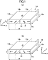
- FIG. 1 is a perspective view showing a dipole-anisotropic rare earth sintered magnet according to an embodiment of the present invention.
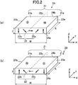
- 1 is a perspective view showing a tripolar anisotropic anisotropic rare earth sintered magnet according to an aspect of an embodiment of the present invention.
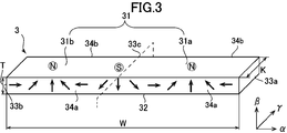
- FIG. FIG. 6 is a perspective view showing a tripolar anisotropic anisotropic rare earth sintered magnet according to another aspect of an embodiment of the present invention. It is a figure which shows an example of the surface magnetic flux density distribution obtained by the rare earth sintered magnet of the unipolar pole anisotropic shown in FIG.
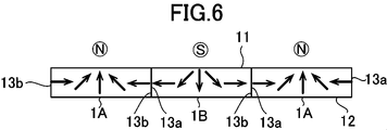
- FIG. It is a figure which shows the usage example of the rare earth sintered magnet shown in FIG. It is a figure which shows an example of the surface magnetic flux density distribution obtained by the rare earth sintered magnet of the bipolar pole anisotropic shown in FIG. It is a figure which shows the usage example of the rare earth sintered magnet shown in FIG. It is a figure which shows an example of the surface magnetic flux density distribution obtained by the rare earth sintered magnet of the tripolar pole anisotropic by the one aspect
- FIG. 1A is a perspective view showing the direction of the axis of a rare earth sintered magnet
- FIG. 2B is an EBSD analysis at the center and both ends of the magnet.
- (C) shows the orientation axis angle in the cross section of the magnet along the A2 axis in (a). It is a figure which shows a part of production
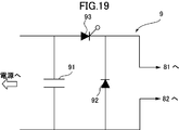
- FIG. 1 It is a perspective view in the edge part of the magnetic field application apparatus which can be used in order to manufacture the rare earth sintered magnet of the two poles anisotropic shown in FIG. It is sectional drawing of the magnetic field application apparatus shown in FIG. It is a figure which shows an example of the electric circuit which can be used in order to generate
- FIG. 1 It is sectional drawing of the magnetic field application apparatus which can be used in order to manufacture the rare earth sintered magnet of the unipolar anisotropic shown in FIG. It is a figure which shows the surface magnetic flux density distribution used in order to obtain
- Rare earth sintered magnet] 1 to 4 are conceptual diagrams showing various structural aspects of rare earth sintered magnets 1 to 4 according to an embodiment of the present invention.
- This direction can correspond to the magnetization direction of the magnet material particles, in other words, the same or substantially the same direction as the magnetization direction of the rare earth sintered magnet.
- the orientation axes in the same direction are formed on the opposite end face, that is, the end face 14b.
- FIG. 1 shows a practically useful surface magnetic flux density only on one surface 11 in the thickness direction “ ⁇ ” or mainly on one surface in the thickness direction.
- 1 is a perspective view showing a rare earth sintered magnet 1 which can generate a magnetic flux having only one polarity of one of N and S poles on one surface 11 thereof.
- 1 shows a rare earth sintered magnet 1A that produces substantially only an N pole on one surface 11, and
- FIG. 1 shows a substantial effect on one surface 11 in particular.
- 1 shows rare earth sintered magnets 1B that generate only the S pole.
- the substantial difference between the rare earth sintered magnet 1A and the rare earth sintered magnet 1B is only in that the polarities exhibited on the surface 11 are opposite, and the other points are substantially the same. You can think of it.
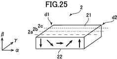
- FIG. 2 shows a practically useful surface magnetic flux density only on one surface 21 in the thickness direction “ ⁇ ” or mainly on one surface in the thickness direction.
- FIG. 2 is a perspective view showing a rare earth sintered magnet 2 that can generate a magnetic flux having one polarity and one polarity of N pole and S pole on the one surface 21;
- the N pole is generated on one side 21a and the S pole is generated on the other side 21b when viewed from the vertical surface 23c located at the center of the width direction “ ⁇ ” on one surface 21.
- the rare earth sintered magnet 2A to be used is shown in FIG. 2B.
- FIG. 2B shows a practically useful surface magnetic flux density only on one surface 21 in the thickness direction “ ⁇ ” or mainly on one surface in the thickness direction.
- FIG. 2 is a perspective view showing a rare earth sintered magnet 2 that can generate a magnetic flux having one polarity and one polarity of N pole and S pole on the one surface 21;
- the N pole is generated on one side 21a
- the S pole is provided on one side 21a as viewed from the vertical surface 23c located at the center of the width direction “ ⁇ ” on one side 21.
- each of the rare earth sintered magnets 2B for generating an N pole on the other side 21b is shown.
- the only substantial difference between the rare earth sintered magnet 2A and the rare earth sintered magnet 2B is that the polarity exhibited by the surface 21 is in the opposite direction, and the other points are substantially the same. You can think of it.
- 3 and 4 are tripolar polar anisotropic rare earth sintered magnets 3 and 4, more specifically, only on one surface 31, 41 in the thickness direction “ ⁇ ” or mainly on one surface in the thickness direction.
- a magnetic flux having a practically useful surface magnetic flux density can be generated, and on the one surface 31, 41, substantially “N pole, S pole, N pole” or “S pole, N pole, S pole”. It is a perspective view which shows the rare earth sintered magnets 3 and 4 which have these in this order.
- the rare earth sintered magnet 3 of FIG. 3 has, on one surface 31 thereof, an S pole at the center in the width direction “ ⁇ ”, and one side 31a and the other side as viewed from the vertical surface 33c located at the center. N poles are generated on each side 31b.
- the rare earth sintered magnet 4 of FIG. 4 has, on one surface 41, an N pole at the center in the width direction “ ⁇ ” and one side 41a when viewed from the vertical surface 43c positioned at the center. S poles are generated on the other side 41b.
- the magnetization is reversed and the surfaces 31 and 41 are exhibited. Magnets with opposite polarities can also be used.
- the rare earth sintered magnet 3 shown in FIG. 3 is obtained by bonding the rare earth sintered magnet 1A and the rare earth sintered magnet 1B shown in FIG. 1 to each other on their side surfaces, more specifically, shown in FIG. It can also be regarded as having substantially the same structure as the structure.
- the rare earth sintered magnet 4 shown in FIG. 4 is obtained by bonding the rare earth sintered magnet 2A and the rare earth sintered magnet 2B shown in FIG. 2 to each other on their side surfaces. It can also be viewed as having substantially the same configuration as part of the structure shown. Therefore, according to the rare earth sintered magnets 3 and 4 of FIG. 3 and FIG. 4, it is possible to obtain a magnet having a shape in which the rare earth sintered magnet 1 and the rare earth sintered magnet 2 are combined without any trouble.
- Each of the rare earth sintered magnets 1 to 4 shown in FIG. 1 to FIG. 4 is orthogonal to each other in the width direction (arrow “ ⁇ ” direction shown in the figure), the thickness direction (arrow “ ⁇ ” direction shown in the figure), and the length direction ( 3D shape having an arrow ( ⁇ direction) as shown. As shown in FIGS. 1 to 4, these may have a rectangular shape, for example. However, it is not always necessary to have a rectangular shape, and it is sufficient to include a three-dimensional shape that can define the width direction, the thickness direction, and the length direction. Therefore, for example, the surface in the width direction and the thickness direction may be arcuate or trapezoidal.
- width direction, thickness direction, and length direction refer to the orientation direction of the easy axis of magnetization, the surface (main surface) that can generate a magnetic flux having a practically useful surface magnetic flux density, and the opposite direction.
- the surface to be used it is merely for convenience. For example, the length relationship between them is not defined.
- the width dimension “W” in the width direction “ ⁇ ” of the rare earth sintered magnets 1 to 4 is preferably small within a practical range, and is 10 mm or more and 40 mm or less in consideration of the performance of a currently available magnetic field application device. 30 mm or less is preferable, 20 mm or less is more preferable, and 10 mm or less is still more preferable. If the width dimension “W” is too small or too large, depending on the currently available magnetic field application devices, a sufficient magnetic field cannot be applied to the sintered body for the rare earth sintered magnet. In order to obtain a desired surface magnetic flux density by magnetization, it is preferable to limit the width dimension in the width direction to a certain size.
- the thickness dimension “t” in the thickness direction “ ⁇ ” is preferably small within a practical range. By reducing the thickness dimension, the size and weight of the magnet unit can be reduced. However, if the thickness dimension is too small, a sufficient surface magnetic flux density cannot be generated, so that it is necessary to be at least 1 mm. On the other hand, if the thickness dimension is too large, a sufficient magnetic field cannot be applied to the sintered body for a rare earth sintered magnet. In order to magnetize, it is thought that it is necessary to be 12 mm or less, 10 mm or less is preferable, 8 mm or less is more preferable, 6 mm or less is more preferable, and 4 mm or less is still more preferable.
- the thickness dimension in the thickness direction is preferably limited to a certain size.
- the length dimension “K” in the length direction “ ⁇ ” can be determined relatively freely, it is preferably 5 mm to 100 mm, and more preferably 5 mm to 100 mm considering the performance of currently available magnetic field application devices. It is 50 mm, more preferably 5 mm to 40 mm.
- FIG. 5 shows an example of the surface magnetic flux density distribution obtained by the unipolar anisotropic rare earth sintered magnet 1 shown in FIG.
- the horizontal axis represents the distance (mm) from the vertical surface 13c located at the center of the rare earth sintered magnet 1 in the width direction “ ⁇ ”, and the vertical axis represents the surface magnetic flux density (mT) at this position.
- the solid line shows the surface magnetic flux density distribution measured at a position away from the one surface 11 by a predetermined distance, for example, 1 mm, in the thickness direction “ ⁇ ” in the direction opposite to the other surface 12
- a broken line indicates a surface magnetic flux density distribution measured at a position away from the other surface 12 by a predetermined distance, for example, 1 mm, in the thickness direction “ ⁇ ” in the opposite direction to the one surface 11.
- the surface magnetic flux density distribution is set to have a substantially symmetrical shape by adjusting the orientation direction of the easy magnetization axis.
- the rare earth sintered magnet 1A shown in FIG. 1A has a predetermined polarity at the central portion (13c) in the width direction “ ⁇ ” on one surface 11;
- a magnetic flux having the maximum surface magnetic flux density (hereinafter referred to as the maximum surface magnetic flux density) D1 of the N pole is generated, and opposite in the vicinity of the side surfaces 13a and 13b located at both ends in the width direction “ ⁇ ”.
- the other surface 12 generates magnetic fluxes having maximum surface magnetic flux densities D2a and D2b having small S poles at positions closer to the side surfaces 13a and 13b than the central portion (13c) in the width direction “ ⁇ ”.
- the magnetic flux having a relatively large surface magnetic flux density D4a, D4b of the S pole is generated at a position further closer to the side surfaces 13a, 13b.
- the rare earth sintered magnet 1 has a central portion (in particular, the central portion ( ⁇ ) in the width direction “ ⁇ ” only on one surface 11 in the thickness direction “ ⁇ ” or mainly on one surface in the thickness direction. In the vicinity of 13c), a magnetic flux having a practically useful surface magnetic flux density is generated.
- the plurality of rare earth sintered magnets 1A and 1B can be brought into contact with each other without substantially repelling the magnetic force. It can also be arranged alternately in the butted state. Thereby, it is possible to easily configure a magnet arrangement in which N poles and S poles are alternately arranged on one surface 11.
- FIG. 7 shows an example of the surface magnetic flux density distribution obtained by the rare earth sintered magnet 2 anisotropic to the two poles shown in FIG.
- the surface magnetic flux density was measured by the same method as in FIG.
- the surface magnetic flux density distribution is set to have a substantially symmetrical shape by adjusting the orientation direction of the easy magnetization axis.
- the surface magnetic flux density is almost zero at the central portion (23c) in the width direction “ ⁇ ” on one surface 21 thereof, and the one surface 21 thereof.
- the other surface 22 generates magnetic fluxes having the maximum surface magnetic flux densities D2a and D2b having the opposite polarity to the one surface 21 at the same position as the one surface 21 in the width direction “ ⁇ ”.
- the maximum surface magnetic flux densities D2a and D2b are much smaller than the maximum surface magnetic flux densities D1a and D1b, and do not cause a leakage magnetic flux that causes a problem.
- the rare earth sintered magnet 2 has a central portion (in particular, the central portion ( ⁇ ) in the width direction “ ⁇ ” only on one surface 21 in the thickness direction “ ⁇ ” or mainly on one surface in the thickness direction.
- the magnetic flux having a practically useful surface magnetic flux density is generated at a position closer to one side surface 23a or the other side surface 23b than 23c).
- the magnetic forces generated on the side surfaces 23a and 23b located at both ends in the width direction “ ⁇ ” cause some repulsion to each other, but the forces are weak. Therefore, as shown in FIG.
- the sintered magnets 2A and 2B can be alternately arranged with their side surfaces 23a and 23b butting each other. As a result, a magnet array in which the N pole and the S pole are alternately arranged on one surface 21 can be configured.
- FIGS. 9 and 10 show examples of surface magnetic flux density distributions obtained by the tripolar anisotropic anisotropic rare earth sintered magnets 3 and 4 shown in FIGS. 3 and 4, respectively.
- the surface magnetic flux density was measured by the same method as in FIG.
- the surface magnetic flux density distribution is set to have a substantially symmetrical shape by adjusting the orientation direction of the easy magnetization axis.
- a predetermined polarity in this case, an S pole, is formed at the central portion (33 c) in the width direction “ ⁇ ” on one surface 31.
- the magnetic flux having the maximum surface magnetic flux density D1c is generated, and one side 31a of the one surface 31 has a predetermined polarity, in this case, at a position close to the one side surface 33a in the width direction “ ⁇ ”.
- An N-pole magnetic flux having the maximum surface magnetic flux D1a is generated, and on the other side 31b of the one surface 31, the one side 31a is located at a position close to the other side surface 33b in the width direction “ ⁇ ”.
- a magnetic flux having the same polarity, that is, N pole and having a maximum surface magnetic flux density D1b is generated.
- the other surface 32 is at the same position as the one surface 31 in the width direction “ ⁇ ”, and the one surface has the same polarity as the maximum surface magnetic flux density D2a, D2b, here, a magnetic flux having a value of approximately zero.
- these maximum surface magnetic flux densities D2a and D2b are very small compared to the maximum surface magnetic flux densities D1a and D1b, and do not cause a leakage magnetic flux that causes a problem.
- the rare-earth sintered magnets 3 and 4 are formed only on one surface 31, 41 in the thickness direction “ ⁇ ” or mainly on one surface in the thickness direction. ”And a practically useful surface at a position closer to one side surface 33a, 43a or the other side surface 33b, 43b than the central portion (33c, 43c) in the width direction“ ⁇ ”. A magnetic flux having a magnetic flux density is generated.
- the rare earth sintered magnets 3 and 4 shown in FIGS. 3 and 4 also have their side surfaces 33a and 33b or the side surfaces 43a and 43b abutted with each other. Can be arranged alternately. Thereby, it is possible to configure a magnet arrangement in which N poles and S poles are alternately arranged on one surface 31, 41.
- any of the rare earth sintered magnets 1 to 4 shown in FIGS. 1 to 4 is practically useful only on one side in the thickness direction “ ⁇ ” or mainly on one side in the thickness direction. Since a magnetic flux having a surface magnetic flux density is generated, it is not necessary to provide a large amount of magnet material on the other surface, and it is not necessary to provide a yoke to capture leakage magnetic flux leaking from the magnetic circuit, or a small amount As a result, these rare earth sintered magnets 1 to 4 are reduced in size and weight.
- the rare earth sintered magnets 1 to 4 shown in FIGS. 1 to 4 magnetize a sintered body for the rare earth sintered magnets 1 to 4 (hereinafter referred to as “sintered body for rare earth sintered magnet”). can get.
- the magnetization process does not substantially change the shape and size of the sintered body for rare earth sintered magnet.
- the sintered body for a rare earth sintered magnet is similar to the rare earth sintered magnets 1 to 4 in the width direction (arrow “ ⁇ ” direction in the figure), the thickness direction (arrow “ ⁇ ” direction in the figure), and the length direction ( It may be considered to have a three-dimensional shape having a direction indicated by an arrow “ ⁇ ” (shown) and a shape corresponding to the rare earth sintered magnets 1 to 4, for example, a rectangular shape as shown in FIGS.
- the size of the sintered body for the rare earth sintered magnet may be considered to be substantially the same as that of the rare earth sintered magnets 1 to 4. Since the body may be slightly polished for leveling, it may have a slightly different size.
- the rare earth magnet forming material from which the sintered body for rare earth sintered magnet is based includes a magnet material containing a rare earth substance.
- a magnet material containing a rare earth substance for example, an Nd—Fe—B based magnet material can be used.
- the Nd—Fe—B based magnet material is, for example, R in weight percentage (R is one or more of rare earth elements including Y) 27.0 to 40.0 wt%, more preferably It may contain 27.0 to 35 wt%, B to 0.6 to 2 wt%, more preferably 0.6 to 1.1 wt%, and Fe as electrolytic iron in a proportion of 60 to 75 wt%.
- the Nd—Fe—B based magnet material contains 27 to 40 wt% Nd, 0.8 to 2 wt% B, and 60 to 70 wt% Fe.
- This magnet material has Dy, Tb, Co, Cu, Al, Si, Ga, Nb, V, Pr, Mo, Zr, Ta, Ti, W, Ag, Bi, Zn, Mg for the purpose of improving magnetic properties.
- a small amount of other elements such as may be included.
- the magnet material is included in the state of fine magnet material particles in the rare earth magnet forming material.
- the rare earth sintered magnets 1 to 4 and the sintered body for rare earth sintered magnet have a configuration in which these magnet material particles are integrally sintered, that is, the magnet material particles are located at any position of the magnet or sintered body. It has a configuration in which the magnets and the sintered body are joined to each other with a specific coupling structure. Therefore, for example, a piece having a desired shape is cut out from the magnet or the sintered body, and a plurality of the cut pieces are joined together. It has a different structure from the magnet and the sintered body for magnet formation.
- Each of the magnet material particles has an easy magnetization axis oriented in a predetermined direction as indicated by an arrow in FIGS.
- These easy magnetization axes are within the plane formed by the “ ⁇ direction” and “ ⁇ direction” in FIGS. 1 to 4, for example, flat front end surfaces 14a, 24a, 34a, 44a, and rear end surface 14b, In each of the planes 24b, 34b, and 44b, they are generally oriented in a predetermined direction indicated by an arrow shown. Furthermore, these easy magnetization axes are oriented in the directions indicated by the arrows in the respective cross sections in the “ ⁇ - ⁇ ” direction orthogonal to the length direction “ ⁇ ”.
- the magnetization direction in the rare earth sintered magnet 1 of FIG. 1 caused by the magnetization is the both ends (13a, 13b) in the width direction “ ⁇ ” and the center portion (13c) in the width direction “ ⁇ ”. However, it is different from 90 ° ⁇ 5 °, and it is not clear from the drawing, but from both end portions (13a, 13b) in the width direction “ ⁇ ” toward the central portion (13c) in the width direction “ ⁇ ”. It gradually changes in the area.
- ⁇ 5 ° is taken into account that some errors may occur depending on the measurement conditions and magnetic field application method. Is not significantly affected (the same applies hereinafter).
- the orientation direction of the easy magnetization axis in the sintered body for rare earth sintered magnet before magnetizing the rare earth sintered magnet 2 in FIG. 2 more specifically, the direction substantially along such orientation direction. 2, the magnetization direction in the rare earth sintered magnet 2 of FIG.
- the easy magnetization axis is not usually polar, it becomes a vector having polarity by magnetizing magnetic material particles. Therefore, in FIGS. 1 to 4, the polarity to be magnetized is taken into consideration. In addition, an arrow in which directivity is given to the easy magnetization axis is shown. That is, in this specification, the term “orientation direction of the easy axis” or a similar term is used to represent the direction in consideration of the polarity to be magnetized in this way.
- the orientation angle means an angle in the direction of the orientation axis of the easy axis of magnetization of the magnetic material particles with respect to a predetermined reference line.
- the section for determining the orientation axis angle is a quadrangular section including at least 30, for example, 200 to 300 magnet material particles, or a square section having a side of 35 ⁇ m.
- Orientation axis angle is an angle between these orientation axes represented by arrows shown in FIGS. 1 to 4 and one reference line.
- the reference line can be set arbitrarily.
- FIG. 11 is a schematic enlarged view showing a procedure for determining the “orientation angle” and the “orientation axis angle” of the easy magnetization axis of each magnetic material particle.
- the quadrangular section R includes a large number of magnet material particles P such as 30 or more, for example, 200 to 300. As the number of magnet material particles included in the quadrangular section increases, the measurement accuracy increases, but even about 30 particles can be measured with sufficient accuracy.
- Each magnet material particle P has an easy axis P-1.
- the easy magnetization axis P-1 of each magnetic material particle P has an “orientation angle” that is an angle between a direction in which the easy magnetization axis is directed and a reference line. Then, among the “orientation angles” of the easy magnetization axes P-1 of the magnet material particles P in the quadrangular section R shown in FIG. 11, the most frequent orientation angle is defined as an “orientation axis angle” B.
- the direction determined by the “orientation axis angle” is defined as the “orientation direction of the easy axis of magnetization”. This direction substantially corresponds to the magnetization direction of the magnet material particles and the “direction of magnetization” and “orientation direction of the easy axis of magnetization” in the rare earth sintered magnets 1 to 4.
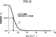
- FIG. 12 is a chart showing a procedure for obtaining the orientation angle variation angle.
- the distribution of the difference ⁇ in the orientation angle of the easy magnetization axes of the individual magnet material particles with respect to the easy magnetization axis is represented by a curve C.
- the position at which the cumulative frequency shown on the vertical axis is maximum is 100%, and the value of the orientation angle difference ⁇ at which the cumulative frequency is 50% is the half width.
- the orientation angle of the easy magnetization axis P-1 in each magnetic material particle P can be obtained by an “electron backscattering diffraction analysis method” (EBSD analysis method) based on a scanning electron microscope (SEM) image.
- EBSD analysis method based on a scanning electron microscope (SEM) image.
- SEM scanning electron microscope
- EBSD detection method AZtecHKL EBSD Nordlys Nano Integrated
- JSM-70001F manufactured by JEOL Ltd., Akishima City, Tokyo, or EDAX.
- SUPER40VP manufactured by ZEISS which is a scanning electron microscope equipped with an EBSD detector manufactured by KK (Hikari High Speed EBSD Detector).
- FIG. 13 shows an example of the orientation display of the easy axis by the EBSD analysis method.
- FIG. 13A is a perspective view showing the direction of the axis of the rare earth sintered magnet, and FIG.
- FIG. 13C shows the orientation axis angle in the cross section of the magnet along the A2 axis.
- the orientation axis angle can be displayed by dividing the orientation vector of the easy magnetization axis of the magnetic material particle into a component in a plane including the A1 axis and the A2 axis and a component in a plane including the A1 axis and the A3 axis.
- the A2 axis is the width direction
- the A1 axis is the thickness direction.
- the center diagram of FIG. 13B shows that the orientation of the easy axis is substantially in the direction along the A1 axis at the center in the width direction of the magnet.
- FIG. 13B shows that the orientation of the easy axis of magnetization at the left end in the width direction of the magnet is inclined from the bottom to the top right along the plane of the A1 axis-A2 axis. Show.
- the diagram on the right side of FIG. 13B shows that the orientation of the easy axis at the right end in the width direction of the magnet is inclined from the bottom to the top left along the plane of the A1 axis-A2 axis.
- FIG. 13C Such an orientation is shown in FIG. 13C as an orientation vector.
- the pole figure shown in FIG. 13B is a pole figure obtained by a SUPRA 40VP manufactured by ZEISS, which is a scanning electron microscope provided with an EBSD detector manufactured by EDAX (Hikari High Speed EBSD Detector).
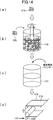
- FIG. 14 shows a part of the production process of the rare earth magnet forming material.
- an ingot of a magnet material made of an Nd—Fe—B alloy having a predetermined fraction is manufactured by a casting method.
- an Nd—Fe—B alloy used in a neodymium magnet has a composition containing Nd of 30 wt%, preferably iron containing 67 wt% and B of 1.0 wt%.
- this ingot is roughly pulverized to a size of about 200 ⁇ m using a known means such as a stamp mill or a crusher.
- the ingot can be melted, flakes can be produced by strip casting, and coarsely pulverized by hydrogen cracking. Thereby, coarsely pulverized magnet material particles 115 are obtained (see FIG. 14A).
- the coarsely pulverized magnet material particles 115 are finely pulverized by a wet method using a bead mill 116 or a dry method using a jet mill.
- the coarsely pulverized magnet particles 115 are finely pulverized in a solvent to a predetermined particle size, for example, 0.1 ⁇ m to 5.0 ⁇ m, and the magnet material particles are dispersed in the solvent (See FIG. 14B).
- the magnet particles contained in the solvent after the wet pulverization are dried by means such as drying under reduced pressure, and the dried magnet particles are taken out (not shown).
- the type of solvent used for grinding is not particularly limited, alcohols such as isopropyl alcohol, ethanol and methanol, esters such as ethyl acetate, lower hydrocarbons such as pentane and hexane, benzene, toluene, xylene and the like.
- Organic solvents such as aromatics, ketones and mixtures thereof, or inorganic solvents such as liquefied nitrogen, liquefied helium, and liquefied argon can be used. In this case, it is preferable to use a solvent containing no oxygen atom in the solvent.
- the coarsely pulverized magnet material particles 115 are subjected to (a) nitrogen gas having an oxygen content of 0.5% or less, preferably substantially 0%, Ar gas, Jet mill in an atmosphere composed of an inert gas such as He gas, or (b) an atmosphere composed of an inert gas such as nitrogen gas, Ar gas or He gas having an oxygen content of 0.0001 to 0.5% To obtain fine particles having an average particle diameter in a predetermined range of 6.0 ⁇ m or less, for example, 0.7 ⁇ m to 5.0 ⁇ m.
- the oxygen concentration being substantially 0% is not limited to the case where the oxygen concentration is completely 0%, but contains oxygen in such an amount as to form an oxide film very slightly on the surface of the fine powder. Means that it may be. If hydrogen remains in the magnetic powder, the organic component is altered, so it is preferable to remove hydrogen from the finely pulverized magnetic powder.
- the temperature may be raised, for example, from room temperature to 120 ° C. or higher for 0.5 hours, and then the temperature may be maintained for a predetermined time, for example, 1 hour or more.
- the magnet material particles finely pulverized by the bead mill 116 or the like are formed into a desired shape.
- a mixture obtained by mixing the finely pulverized magnet material particles and the binder made of the resin material as described above, that is, a composite material is prepared.
- the resin used as the binder is preferably a depolymerizable polymer that does not contain an oxygen atom in the structure.
- the composite material of the magnet particles and the binder can be reused for the remainder of the composite material generated when the composite material is formed into a desired shape, and the composite material is heated and softened. It is preferable to use a thermoplastic resin as the resin material so that the magnetic field orientation can be performed.
- a polymer composed of one or two or more polymers or copolymers formed from the monomer represented by the following general formula (1) is preferably used.
- R 1 and R 2 represent a hydrogen atom, a lower alkyl group, a phenyl group or a vinyl group.
- polystyrene-butadiene block copolymer which is a copolymer of styrene and isoprene (SIS), butyl rubber (IIR) which is a copolymer of isobutylene and isoprene, styrene-butadiene block copolymer (SBS) which is a copolymer of styrene and butad
- Ethylene-butadiene-styrene Copolymer SEBS
- SEPS styrene-ethylene-propylene-styrene copolymer
- EPM ethylene-propylene copolymer
- EPDM obtained by copolymerization of a diene monomer with ethylene and propylene
- 2-methyl-1-pentene polymer resin that is a polymer of 2-methyl-1-pentene
- 2 polymer that is 2-methyl-1-butene -Methyl-1-butene polymer resin PEBS
- SEPS styrene-ethylene-propylene-styrene copolymer
- EPM ethylene-propylene copolymer
- the resin used for the binder may include a small amount of a polymer or copolymer of a monomer containing an oxygen atom or a nitrogen atom (for example, polybutyl methacrylate, polymethyl methacrylate, etc.). Furthermore, a monomer that does not correspond to the general formula (1) may be partially copolymerized. Even in that case, the object of the present invention can be achieved.
- thermoplastic resin that softens at 250 ° C. or lower in order to appropriately perform magnetic field orientation, more specifically, a thermoplastic resin having a glass transition point or a flow start temperature of 250 ° C. or lower is used. It is desirable.
- an alignment lubricant As the alignment lubricant, alcohol, carboxylic acid, ketone, ether, ester, amine, imine, imide, amide, cyan, phosphorus functional group, sulfonic acid, compound having unsaturated bond such as double bond and triple bond, It is desirable to add at least one of the liquid saturated hydrocarbon compounds. A mixture of a plurality of these substances may be used. As will be described later, when applying a magnetic field to a mixture of magnet material particles and a binder, that is, a composite material to magnetically orient the magnet material, the mixture is heated so that the binder component is softened and magnetic field orientation is performed. Process.
- the amount of carbon remaining in the sintered body after sintering can be 2000 ppm or less, more preferably 1000 ppm or less.
- the amount of oxygen remaining in the sintered body after sintering can be 5000 ppm or less, more preferably 2000 ppm or less.
- the amount of the binder added is an amount that can appropriately fill the gaps between the magnetic material particles so as to improve the thickness accuracy of the molded product obtained as a result of molding when molding a slurry or a heat-melted composite material.
- the ratio of the binder to the total amount of the magnetic material particles and the binder is 1 wt% to 40 wt%, more preferably 2 wt% to 30 wt%, still more preferably 3 wt% to 20 wt%, and particularly preferably 5 wt% to 15 wt%. .
- the ratio of the resin to the total amount of the resin used for the binder and the magnetic material particles is preferably 1 wt% to 30 wt%, more preferably 2 wt% to 20 wt%, still more preferably 3 wt% to 15 wt%, and particularly preferably 3.5 wt% to 12 wt%.
- a mixture of magnetic material particles and a binder that is, a composite material 117 is once formed into a sheet-shaped green molded body (hereinafter referred to as “green sheet”), and then a molded body shape for orientation treatment is used.
- the composite material is particularly formed into a sheet shape, for example, by heating the composite material 117 that is a mixture of magnet material particles and a binder and then forming into a sheet shape, or by combining the magnet material particles and the binder
- a method in which the composite material 117 which is a mixture is placed in a mold and heated and pressed by a method in which the composite material is molded by extrusion using an extrusion molding machine, or by including magnetic material particles, a binder, and an organic solvent Forming by slurry coating or the like that forms a sheet by coating the slurry on the substrate can be employed.
- the molding may be performed by putting the composite material 117 in a molding die and pressurizing to a pressure of 0.1 to 100 MPa while heating to room temperature to 300 ° C.
- a method in which the composite material 117 heated to a softening temperature is pressed and filled into a mold by applying an injection pressure is possible to employ a method in which the composite material 117 heated to a softening temperature is pressed and filled into a mold by applying an injection pressure.
- a binder As already described, by mixing a binder with magnetic material particles finely pulverized by a bead mill 116 or the like, a clay-like mixture composed of magnet material particles and a binder, that is, a composite material 117 is produced.
- a binder as described above, a mixture of a resin and an alignment lubricant can be used.
- the resin it is preferable to use a thermoplastic resin that does not contain an oxygen atom in the structure and is made of a depolymerizable polymer.
- the alignment lubricant alcohol, carboxylic acid, ketone, ether, It is preferable to add at least one of an ester, amine, imine, imide, amide, cyan, phosphorus functional group, sulfonic acid, and a compound having an unsaturated bond such as a double bond or a triple bond.
- a compound having an unsaturated bond examples include a compound having a double bond and a compound having a triple bond, and in particular, the effect of reducing cracks in the sintered body. From the viewpoint that can be expected, a compound having a triple bond is more preferable.
- the compound having a triple bond it is preferable to use a compound that can be easily removed in a calcining process described later.
- the compound used preferably has no hetero atom, and is a hydrocarbon.
- Particularly preferred is a compound composed solely of
- the compound having a triple bond is preferably a compound having a triple bond at the terminal.
- the number of carbons as its constituent elements is preferably 10 or more, and more preferably 14 or more, in order to facilitate handling by increasing the boiling point. 16 or more, more preferably 18 or more.
- the upper limit of carbon number is not specifically limited, For example, it can be 30 or less.
- a compound having a functional group having a hetero atom is used in order to be able to interact more strongly with the surface of the magnetic material particles and to exert a high orientation lubricating effect. It is preferable to use a compound having a functional group having a hetero atom at the terminal.
- the number of carbon atoms in the compound having a double bond is preferably 6 or more, more preferably 10 or more, still more preferably 12 or more, and particularly preferably 14 or more. Although the upper limit of carbon number is not specifically limited, For example, it can be 30 or less.
- the above compound having a triple bond and the above compound having a double bond may be used in combination.
- the amount of the binder added is such that the ratio of the binder to the total amount of the magnetic material particles and the binder in the composite material 117 after the addition is 1 wt% to 40 wt%, more preferably 2 wt% to 30 wt%. Is 3 wt% to 20 wt%, particularly preferably 5 wt% to 15 wt%.
- the ratio of the resin to the total amount of the resin used for the binder and the magnetic material particles is preferably 1 wt% to 30 wt%, more preferably 2 wt% to 20 wt%, still more preferably 3 wt% to 15 wt%, and particularly preferably 3.5 wt% to 12 wt%.
- the addition amount of the oriented lubricant is preferably determined according to the particle size of the magnet material particles, and it is recommended that the addition amount be increased as the particle size of the magnet material particles is smaller.
- the specific addition amount is 0.01 to 20 parts by weight, more preferably 0.3 to 10 parts by weight, still more preferably 0.5 to 5 parts by weight with respect to 100 parts by weight of the magnetic material particles. Part by weight, particularly preferably 0.8 to 3 parts by weight.
- the addition amount is small, the dispersion effect is small and the orientation may be lowered.
- there is too much addition amount there exists a possibility of contaminating a magnet material particle.
- the orientation lubricant added to the magnet material particles adheres to the surface of the magnet material particles, disperses the magnet material particles, gives a clay-like mixture, and rotates the magnet material particles in the orientation process in the magnetic field described later. Acts to assist. As a result, orientation is easily performed when a magnetic field is applied, and the easy magnetization axis directions of the magnet particles can be aligned in substantially the same direction, that is, the degree of orientation can be increased. In particular, when a binder is mixed with magnetic material particles, the binder is present on the surface of the particles, which increases the frictional force during magnetic field alignment treatment, which may reduce the orientation of the particles. The effect of adding more increases.
- the mixing of the magnet material particles and the binder is preferably performed in an atmosphere made of an inert gas such as nitrogen gas, Ar gas, or He gas.
- the mixing of the magnet material particles and the binder is performed, for example, by putting the magnet material particles and the binder into a stirrer and stirring with the stirrer. In this case, heating and stirring may be performed to promote kneading properties.
- the binder is added to the solvent and kneaded without taking out the magnet particles from the solvent used for pulverization, and then the solvent is volatilized. May be obtained.
- the green sheet described above is created by forming the composite material 117 into a sheet shape.
- the composite material 117 is heated to melt the composite material 117 so as to have fluidity, and then applied onto the support substrate 118. Thereafter, the composite material 117 is solidified by heat radiation, and a long sheet-like green sheet 119 is formed on the support base 118 (see FIG. 14D).
- the temperature at which the composite material 117 is heated and melted varies depending on the type and amount of the binder used, but is usually 50 ° C. to 300 ° C. However, the temperature needs to be higher than the flow start temperature of the binder to be used.
- slurry coating When slurry coating is used, magnetic material particles, a binder, and optionally an alignment lubricant that promotes alignment are dispersed in a large amount of solvent, and the slurry is coated on the support substrate 118. Work. Thereafter, the long sheet-like green sheet 119 is formed on the support substrate 118 by drying and volatilizing the solvent.
- the die method and the comma coating method are particularly excellent in layer thickness controllability, that is, a method capable of applying a high-accuracy thickness layer to the surface of the substrate.
- the composite material 117 heated and fluidized is pumped by a gear pump, injected into the die, and discharged from the die for coating.
- the composite material 117 is fed into the nip gap between two heated rolls in a controlled amount, and the composite material 117 melted by the heat of the roll on the support substrate 118 while rotating the roll.
- a silicone-treated polyester film is preferably used as the support substrate 118.
- the composite material 117 melted by extrusion molding or injection molding is extruded on the support substrate 118 while being molded into a sheet shape, thereby forming a green on the support substrate 118.
- the sheet 119 can also be formed.
- the composite material 117 is applied using the slot die 120.
- the sheet thickness of the green sheet 119 after coating is measured, and the nip between the slot die 120 and the support substrate 118 is controlled by feedback control based on the measured value. It is desirable to adjust the gap. In this case, it is possible to reduce the fluctuation of the amount of the fluid composite material 117 supplied to the slot die 120 as much as possible, for example, to suppress the fluctuation to ⁇ 0.1% or less, and also to reduce the fluctuation of the coating speed as much as possible. For example, it is desirable to suppress fluctuations of ⁇ 0.1% or less. By such control, it is possible to improve the thickness accuracy of the green sheet 119.
- the thickness accuracy of the formed green sheet 119 is preferably within ⁇ 10%, more preferably within ⁇ 3%, and even more preferably within ⁇ 1% with respect to a design value such as 1 mm.
- a design value such as 1 mm.
- the thickness of the green sheet 119 is preferably set in the range of 0.05 mm to 20 mm. If the thickness is less than 0.05 mm, it is necessary to carry out multilayer lamination in order to achieve the necessary magnet thickness, so that productivity is lowered.
- a processing sheet piece cut out to a size corresponding to a desired magnet size is created from the green sheet 119 formed on the support substrate 118 by the hot melt coating described above. Since the processing sheet piece is filled in a sintering mold later and is a source of a rare earth sintered magnet, it can be regarded as an example of a rare earth magnet forming material. Further, since the green sheet 119 is a material of the processing sheet piece and is a source of the rare earth sintered magnet, it is of course included in the concept of the rare earth magnet forming material. Furthermore, as will be described later, not only the molded body manufactured by the green sheet method described above, but also a molded body manufactured by the compacting method can be used as the rare earth magnet forming material, for example. This point will be described later.
- the shape is a shape that takes into account the rare-earth sintered magnets 1 to 4 that are the final product, and the actual size to be cut out is the size in the pressing direction in the sintering process. Is determined so that a predetermined magnet size can be obtained after the sintering process. As will be described later, since the sintering process is performed by pressure sintering, the processing sheet piece is contracted in the pressing direction (the length direction “ ⁇ ” in FIGS. 1 to 4).
- the difference between the rare-earth sintered magnets 1 to 4 that are the final product and the processing sheet piece is that of the rare-earth sintered magnets 1 to 4 that are the final product.
- the length along the pressing direction “ ⁇ ” only shrinks to about half of the length of the processing sheet piece in the same direction “ ⁇ ”. Since the rare earth sintered magnets 1 to 4 are obtained by magnetizing a sintered sheet piece, the sintered body obtained by sintering the processing sheet piece is also a rare earth sintered magnet 1. It may be considered that it has the same shape and dimensions as 4 to 4.
- the surface temperature (hereinafter referred to as “orientation temperature”) of the processing sheet piece after application of the magnetic field is 50 ° C. to 150 ° C., preferably 60 ° C. to 120 ° C.
- the temperature and time for heating the processing sheet piece vary depending on the type and amount of the binder used, but are, for example, 40 to 250 ° C. and 0.1 to 60 minutes. In any case, in order to soften the binder in the processing sheet piece, the heating temperature needs to be higher than the glass transition point or the flow start temperature of the binder used.
- a means for heating the processing sheet piece for example, there is a system using a hot plate or a heat medium such as silicone oil as a heat source.
- the strength of the magnetic field in the application of the magnetic field can be 5000 [Oe] to 150,000 [Oe], preferably 10,000 [Oe] to 120,000 [Oe], and particularly preferably 25000 [Oe] to 70000 [Oe]. .
- the easy axis of magnetization of the crystal of the magnet material particles contained in the processing sheet piece is oriented in the direction along the magnetic field.
- a configuration in which a magnetic field is simultaneously applied to a plurality of processing sheet pieces may be employed.
- a mold having a plurality of cavities is used, or a plurality of molds are arranged and a magnetic field is applied simultaneously.
- the step of applying a magnetic field to the processing sheet piece may be performed simultaneously with the heating step, or may be performed after the heating step and before the binder of the processing sheet piece is solidified.
- the processed sheet piece after orientation in which the easy axis of magnetization is oriented is subjected to atmospheric pressure or a pressure higher or lower than atmospheric pressure, for example, 0.1 MPa to 70 MPa, preferably 1.0 Pa.
- the calcination treatment is performed by holding at the binder decomposition temperature for at least 2 hours or more, preferably several hours to several tens hours, for example, 5 hours.
- the amount of hydrogen supplied during the calcination is 2 to 6 L / min, for example, 5 L / min.
- the binder in other words, the organic compound contained in the composite in which the magnet material particles are mixed with the thermoplastic resin is decomposed into monomers by a depolymerization reaction or other reaction, and then dispersed and removed. It becomes possible. That is, a decarbonization process, which is a process for reducing the amount of carbon remaining in the processing sheet piece, is performed. Further, the calcination treatment is desirably performed under the condition that the amount of carbon remaining in the processing sheet piece is 2000 ppm or less, more preferably 1000 ppm or less.
- the entire processing sheet piece can be densely sintered by the subsequent sintering treatment, and the decrease in residual magnetic flux density and coercive force can be suppressed.
- a pressure shall be 15 Mpa or less.
- the pressurizing condition is a pressure higher than the atmospheric pressure, more specifically 0.2 MPa or more, the effect of reducing the residual carbon amount can be expected.
- the temperature of the calcining treatment may be 250 ° C. to 600 ° C., more preferably 300 ° C. to 550 ° C., for example 450 ° C., depending on the type of binder.
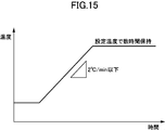
- a preferable result can be obtained by setting the temperature rising rate to 2 ° C./min or less, for example, 1.5 ° C./min. Therefore, when performing the calcination treatment, as shown in FIG. 15, the temperature is increased at a predetermined temperature increase rate of 2 ° C./min or less, and after reaching a preset temperature, that is, a binder decomposition temperature, The calcination treatment is performed by maintaining the set temperature for several hours to several tens of hours.
- the carbon in the processing sheet piece is not removed rapidly, but is removed step by step. It becomes possible to increase the density of the sintered body for forming a permanent magnet after sintering by reducing the amount of carbon. That is, by reducing the amount of residual carbon, the voids in the permanent magnet can be reduced.
- the rate of temperature rise is about 2 ° C./min
- the density of the sintered body for forming a permanent magnet after sintering can be 98% or more, for example, 7.40 g / cm 3 or more, It can be expected to achieve high magnet characteristics in the magnet after magnetization.
- a deoiling treatment for volatilizing oil components such as an alignment lubricant and a plasticizer may be performed.
- the temperature of the deoiling treatment may be 60 ° C. to 120 ° C., more preferably 80 ° C. to 100 ° C., depending on the type of oil component contained.
- a preferable result can be obtained by setting the temperature rising rate to 5 ° C./min or less, for example, 0.7 ° C./min.
- a more preferable result is obtained by performing the oil removal step in a reduced pressure atmosphere, and it is preferable to perform it under a reduced pressure of 0.01 Pa to 20 Pa, more preferably 0.1 Pa to 10 Pa. Note that the magnetic characteristics of the rare earth sintered magnet as the final product do not change depending on whether or not the oil removal treatment is performed.
- FIG. 16 the outline of the heat processing performed at a sintering process is shown.
- the horizontal axis represents time, and the vertical axis represents temperature (° C.).
- the sintering process includes a high-temperature heat treatment “B” (heat treatment 1) performed thereafter and a low-temperature heat treatment “C” (heat treatment 2) performed thereafter.
- the characteristics of the sintered body obtained through the sintering process “A” and the rare-earth sintered magnet that is the final product especially by performing the high-temperature heat treatment “B”. Can be significantly improved.
- the high-temperature heat treatment “B” and the low-temperature heat treatment “C” will be described as part of the sintering process. As will be apparent from the following description, these treatments are merely heat treatments, and the sintering treatment “ This is different from the pressure sintering in “A”.
- the sintering step is performed in a state where the processing sheet pieces are filled in a sintering mold (not shown) consisting of a pair of male and female molds prepared in advance.
- the sintering mold includes a cavity having a shape corresponding to the rare earth sintered magnet as the final product, for example, a cavity having a cross section corresponding to the processing sheet.
- the easy axis of the processing sheet piece is oriented in one plane, that is, formed by the width direction “ ⁇ ” and the thickness direction “ ⁇ ” in FIGS. In an aligned plane.
- ⁇ Sintering process> In the sintering process “A”, the calcined processing sheet piece is sandwiched between a male mold and a female mold and subjected to press pressure to be heated and fired while applying pressure. Bonding, that is, pressure sintering.
- the pressing direction is a direction (length direction “ ⁇ ” in FIGS. 1 to 4) orthogonal to the orientation direction of the easy axis of the processing sheet piece (the arrow direction in FIGS. 1 to 4). By applying pressure in this direction, it is possible to suppress the change in the orientation of the easy axis of magnetization given to the magnet material particles, and a sintered body with higher orientation can be obtained.
- the initial load when sandwiched between the male mold and the female mold is set to a relatively small constant pressure such as 0.5 MPa (the initial load is not particularly shown in FIG. 16). ). However, it is not always necessary to apply the initial load.
- the processing sheet piece is heated from room temperature to the pressure increase start temperature.
- the temperature increase is preferably performed at a constant temperature increase rate.
- the temperature raising rate may be 3 ° C./min to 30 ° C./min, for example, 20 ° C./min.
- Boosting starts, for example, when the temperature reaches 300 ° C. (in the example shown in FIG. 16, the boosting start temperature is shown as about 700 ° C.).
- the fusion of the magnet material particles contained in the rare earth magnet forming material starts, and the strength of the rare earth magnet forming material increases, so that the rare earth magnet forming material does not crack. This is because sintering can be performed while applying pressure. Therefore, it is sufficient that the temperature reaches at least 300 ° C., and of course, boosting may be started at a temperature of 300 ° C. or higher. More preferably, the pressure increase is started in the range of 500 ° C. to 900 ° C., more preferably in the range of 700 ° C.
- the pressure increase rate may be 14 kPa / second or more, for example.
- the final ultimate load (pressing force) is, for example, 1 MPa to 30 MPa, preferably 3 MPa to 30 MPa, more preferably 3 MPa to 15 MPa.
- the pressure is smaller than 3 MPa, the contraction of the processing sheet piece 3 occurs not only in the pressurizing direction but also in all directions, or the processing sheet piece 3 undulates. Even if the high-temperature heat treatment “B” is performed, it becomes difficult to control the shape and the like of the magnet that is the final product.
- the pressurization is continued until the contraction rate in the pressurization direction becomes substantially zero for a predetermined time even after reaching the final ultimate load.
- the “predetermined time” here is, for example, a case where the rate of change per 10 seconds in the pressurizing direction is maintained at zero for about 5 minutes. After confirming that the shrinkage rate in the pressing direction is substantially zero, pressurization is terminated.
- the processing sheet piece 3 is heated at the above-described constant temperature increase rate until the predetermined maximum temperature is reached.
- the maximum temperature reached is preferably set higher than 900 ° C. in a reduced pressure atmosphere of several Pa or less, for example.
- the temperature is 900 ° C. or lower, voids are generated in the processing sheet piece 3, and when the high temperature heat treatment “B” is performed thereafter, the contraction of the processing sheet piece 3 is not only in the pressing direction but also in all directions. Therefore, it becomes difficult to control the shape and the like of the magnet that is the final product.
- the maximum temperature By setting the maximum temperature to be higher than 900 ° C., the shape can be easily controlled.
- the maximum temperature reached is preferably determined in consideration of the average particle diameter and composition of the magnet material particles forming the processing sheet piece 3. Generally, when the average particle size is large, the temperature needs to be higher, and even in the case of a composition with a small amount of rare earths, the temperature needs to be higher. In addition, it is preferable to reach
- a sintered body for forming a rare earth sintered magnet having a desired shape referred to as a sintered body “1A” for convenience.
- a sintered body “1A” for convenience.
- the rare-earth sintered magnets 1 to 4 as the final product and the sintered body 1A have the same size and shape, the rare-earth sintered magnets 1 to 4 shown in FIGS. 1 to 4 are the sintered body 1A. (It is the same for sintered bodies “1B” and “1C” described later).
- the calcined processing sheet piece is perpendicular to the orientation direction of the easy magnetization axis (the arrow direction in FIGS. 1 and 2) (the length direction in FIGS. 1 to 4).
- the orientation of the axis of easy magnetization given to the magnet material particles in the processing sheet piece is changed by heating to the sintering temperature while applying a predetermined amount of pressure to " ⁇ ") Can be suppressed. Therefore, according to this method, a magnet with higher orientation can be obtained.
- the resin material in the processing sheet piece for example, the thermoplastic resin, is scattered (transpiration) by the sintering heat, and the residual resin amount remains. Therefore, the sintered body 1A in which the magnet material particles in which the resin is dispersed is integrally sintered can be formed.
- Examples of the pressure sintering technique used in the sintering process “A” include hot press sintering, hot isostatic pressing (HIP) sintering, ultrahigh pressure synthetic sintering, gas pressure sintering, and discharge plasma ( Any known technique such as SPS) sintering may be employed.
- HIP hot isostatic pressing
- SPS gas pressure sintering
- ⁇ High-temperature heat treatment (heat treatment 1)>
- the sintered body 1A subjected to the sintering process “A” is cooled to room temperature, and then heated again to a predetermined temperature by high-temperature heat treatment “B”.
- the cooling to room temperature may be natural cooling.
- the heating is performed under a reduced pressure atmosphere, more specifically, at a pressure lower than the applied pressure in the sintering process “A”. Note that a reduced-pressure atmosphere is not necessary as long as the atmosphere is an inert gas atmosphere such as argon gas, nitrogen gas, or helium gas.
- the sintered body 1A reaches the maximum temperature preset for the high temperature heat treatment within a predetermined time, for example, within 10 hours, more preferably within 5 hours, and even more preferably within 2 hours.
- the maximum attainable temperature set for the high-temperature heat treatment is set to be higher than 900 ° C and not higher than 1100 ° C. Further, the set temperature is set so that the difference from the maximum temperature reached in the sintering process “A” is within 250 ° C., preferably within 150 ° C., and more preferably within 100 ° C.
- the temperature is held for a predetermined time (section “b” shown in FIG. 16), for example, 1 to 50 hours.
- this holding time is preferably determined in relation to the maximum temperature reached.
- the maximum temperature and holding time may vary somewhat, and it is sufficient if the temperature is held for about 1 to 50 hours near the maximum temperature.
- the maximum temperature reached and the holding time satisfy the following relationship. -1.13x + 1173 ⁇ y ⁇ ⁇ 1.2x + 1166 (however, 1100 ° C ⁇ x> 900 ° C)
- x (° C.) represents the maximum temperature reached
- y (time) represents the holding time near the maximum temperature reached.
- the setting of the maximum temperature reached is also affected by the average particle diameter of the magnet material particles after pulverization. For example, it is preferably set to be higher than 900 ° C. for an average particle size of 1 ⁇ m and 1100 ° C. or less for an average particle size of 5 ⁇ m.
- the average particle size is measured using a laser diffraction / scattering particle size distribution measuring device (device name: LA950, manufactured by HORIBA). Specifically, after gradually pulverizing the finely pulverized magnet material particles at a relatively low oxidation rate, several hundred mg of the gradually oxidized powder is added to silicone oil (product name: KF-96H-1 million cs, manufactured by Shin-Etsu Chemical). Was mixed into a paste, and was sandwiched between quartz glasses as a test sample (HORIBA paste method), and the value of D50 in the graph of particle size distribution (volume%) was defined as the average particle size. However, when the particle size distribution was a double peak, the average particle size was determined by calculating D50 for only the peak having a small particle size.
- silicone oil product name: KF-96H-1 million cs, manufactured by Shin-Etsu Chemical
- ⁇ Low-temperature heat treatment (heat treatment 2)>
- the sintered body that has been subjected to the high-temperature heat treatment “B” (referred to as a sintered body “1B” for convenience) is cooled again to room temperature, and then heated to a predetermined temperature again by the low-temperature heat treatment “C”.
- the cooling to room temperature may be natural cooling.
- the heating is performed in a reduced pressure atmosphere as in the high temperature heat treatment “B”.
- a reduced-pressure atmosphere is not necessary as long as the atmosphere is an inert gas atmosphere such as argon gas, nitrogen gas, or helium gas.
- the temperature of the sintered body 1B is increased so as to reach the maximum temperature preset for the low temperature heat treatment within a predetermined time, for example, within 10 hours, preferably within 5 hours, and more preferably within 2 hours.
- the maximum temperature set for the low-temperature heat treatment is set to be lower than the high-temperature heat treatment temperature, for example, 350 ° C. to 650 ° C., preferably 450 ° C. to 600 ° C., more preferably 450 ° C. to 550 ° C. .
- the temperature is held for a predetermined time (section “c” shown in FIG. 16), for example, 2 hours. It is preferable to perform rapid cooling immediately after completion of the holding.
- a sintered body that has been subjected to low-temperature heat treatment (referred to as a sintered body “1C” for convenience) can be magnetized using, for example, the magnetic field application device 5 described below.
- the magnetic field application device 5 is not necessarily used, and other general magnetic field application devices that are currently available may be used.
- the sintered body 1C becomes the rare earth sintered magnet 1.
- the magnetized rare earth sintered magnet 1 is then installed in, for example, a linear motor.
- FIGS. 17 and 18 show an example of a magnetic field applying device 5 that can be used to manufacture a rare earth sintered magnet having a two-pole anisotropic property, for example, the rare earth sintered magnet 2 shown in FIG.
- FIG. 17 is a perspective view of the end portion of the magnetic field application device 5
- FIG. 18 is a cross-sectional view along the “ ⁇ - ⁇ ” direction orthogonal to the length direction “ ⁇ ” of the magnetic field application device 5.
- a magnetic field can be applied to a workpiece, for example, a processing sheet piece that is an example of a rare earth magnet forming material, and the easy axis of magnetization of the magnet material particles can be oriented.
- the rare earth sintered magnet 2 can be manufactured by magnetizing a sintered body for rare earth sintered magnet.
- the orientation direction of the easy magnetization axis and the magnetization direction in other words, the magnetization direction of the rare earth sintered magnets 1 to 4 can be easily determined. And can be magnetized with higher accuracy. However, it is not always necessary to use the device 5 for both orientation and magnetization.
- the magnetic field application device 5 has a symmetrical shape in the width direction “ ⁇ ” and includes a magnetic yoke 60 extending in the length direction “ ⁇ ” and a pair of nonmagnetic yokes 51A and 51B extending in the length direction “ ⁇ ”. And a nonmagnetic yoke 51.
- the magnetic yoke 60 includes a pair of yoke legs 61A and 61B extending in the length direction “ ⁇ ” and a recess 62 extending between the pair of yoke legs 61A and 61B and extending in the length direction “ ⁇ ”. .
- the pair of yoke legs 61A and 61B have flat upper surfaces 61a and 61b, respectively, and are positioned with an interval “w3” in the width direction “ ⁇ ”.
- the pair of non-magnetic yokes 51A and 51B are respectively disposed on the upper surfaces 61a and 61b of the pair of yoke legs 61A and 61B.
- the magnetic material yoke 60 is positioned with respect to the corresponding yoke legs 61A and 61B so that the workpiece placement surfaces 61a1 and 61b1 having a predetermined width “w2” are left on the side adjacent to the recess 62 of the magnetic yoke 60.
- a workpiece placement portion 67 having a cavity having a shape corresponding to the workpiece is formed.
- the work placing portion 67 is formed between the pair of nonmagnetic yokes 51A and 51B so as to straddle the concave portion 62 of the magnetic yoke 60 in the width direction “ ⁇ ”.
- the workpiece placement unit 67 may be provided with a magnetic field application mold 70 for accommodating the workpiece.
- the mold 70 includes a bottom 72, side walls 73a and 73b spaced apart from each other in the width direction “ ⁇ ”, and a front wall 73c and a rear wall 73d (not shown) spaced from each other in the length direction “ ⁇ ”. It is prescribed. An access opening is provided above the mold 70 to accommodate the workpiece. However, the mold 70 is not necessarily required.
- a coil having a substantially linear portion may be used.
- These coils include, for example, a first conductor 81 (81A, 81B), a second conductor 82A, and a third conductor 82B, some of which are arranged along the length direction “ ⁇ ”. included.
- the first conductor 81 is disposed in the recess 62
- the second conductor 82A is disposed on the side opposite to the recess 62 with respect to the yoke leg 61A in the width direction “ ⁇ ”
- the third conductor 82B is disposed in the width direction.
- the first conductor 81 may be composed of a pair of conductors 81A and 81B spaced apart in the width direction “ ⁇ ”.
- the direction of the current flowing through the conductor 81 and the direction of the current flowing through the conductors 82A and 82B are opposite to each other.
- the conductor 81A disposed on the side close to the yoke leg 61A in the width direction “ ⁇ ” may be connected to the second conductor 82A through, for example, the loop portion 83A, and in the width direction “ ⁇ ”.
- the conductor 81B disposed on the side close to the yoke 61B may be coupled to the third conductor 82B through, for example, the loop portion 83B. By connecting the conductors, currents in opposite directions can flow through these conductors at once.
- the diameter of the conductor is not particularly limited, but from the viewpoint of stabilizing the magnetic field, a conductor having a diameter of 1.4 mm can be used here.
- FIG. 19 shows an example of an electric circuit that can be used to generate a pulsed magnetic field.
- the electric circuit 9 includes a capacitor 91 and a diode 92 connected in parallel to a power source (not shown), and a thyristor 93 connected in series between them.
- the current supplied from the power source is stored in a capacitor 91 having a predetermined capacity, and then, using the thyristor 93, the first conductors 81A and 81B, the second conductor 82A, and the third conductor 82B.
- a pulse current having a predetermined peak current (kA) and a predetermined pulse width (ms) is passed a predetermined number of times.
- a predetermined pulse magnetic field is applied from the conductors 81 and 82 to the workpiece.
- the peak current may be set to about 12 kA and the pulse width may be set to about 0.7 ms, for example.
- the peak current is preferably 10 kA to 30 kA, more preferably 10 kA to 20 kA, and the pulse width is preferably 0.3 ms to 500 ms, more preferably 0.5 ms to 100 ms.
- FIG. 20 shows an example of use of the device 5 shown in FIGS.
- the pulse magnetic field is applied in a state where pressure is applied in the thickness direction “ ⁇ ”, for example, by pressing the upper part of the work 6 with a pressing plate 66 or the like.
- An arrow shown in FIG. 20 shows an example of a magnetic field formed by applying a pulsed magnetic field, and in particular, a magnetic field formed when a current is passed through the conductors 81 and 82 in the direction shown in the drawing.
- the magnetic field used when manufacturing the rare earth sintered magnet 2A shown in FIG. As is apparent, when the rare earth sintered magnet 2B shown in FIG.
- a current is passed through the conductors 81 and 82 in the direction opposite to the direction shown in FIG.
- a magnetic field in the direction opposite to the arrow may be formed.
- the conductor 81A and the conductor 82A mainly form a magnetic field that orients or magnetizes one side in the workpiece width direction “ ⁇ ”
- the conductor 81B and the conductor 82B mainly have a workpiece width.
- a magnetic field that orients or magnetizes the other side in the direction “ ⁇ ” is formed, and the conductor 81A and the conductor 81B mainly form a magnetic field that penetrates the workpiece in the direction “ ⁇ ”.
- the magnetic field formed when a current is passed through the conductors 81 and 82 in the direction shown in the figure is mainly applied to the workpiece 6 placed on the workpiece placing portion 67 from the yoke leg 61A to the upper surface 61a of the yoke leg 61A.
- a portion 61b1 corresponding to the workpiece placement surface of the upper surface 61b of the yoke leg 61B passes through the workpiece 6 placed on the workpiece placement portion 67 in the width direction “ ⁇ ” through the portion 61a1 corresponding to the workpiece placement surface. Then, the yoke leg 61B is reached.
- FIG. 21 and FIG. 22 show an example of a magnetic field applying device 5A that can be used to manufacture a rare earth sintered magnet with three poles anisotropic, for example, the rare earth sintered magnet 4 shown in FIG.
- FIGS. 18 and 20 These drawings correspond to FIGS. 18 and 20 described above, and the same members as those shown in FIG. 18 and the like are denoted by the same reference numerals.
- the magnetic field application device 5A includes a magnetic yoke 60B having a symmetrical shape in the width direction “ ⁇ ” and extending in the length direction “ ⁇ ”.
- the magnetic yoke 60B includes a pair of yoke legs 61A and 61B extending in the length direction “ ⁇ ”, as in the device 5 shown in FIG.
- the pair of yoke legs 61A and 61B have flat upper surfaces 61a and 61b, respectively, and are positioned with an interval “w3” in the width direction “ ⁇ ”.
- the magnetic yoke 60B further includes a plurality of additional arms positioned at intervals “wA”, “wB”, “wD”, and “wE” in the width direction “ ⁇ ” therebetween.
- the yoke legs 61C, 61D, 61E are formed between the pair of yoke legs 61A, 61B and the additional yoke legs 61C, 61D, 61E and between the additional yoke legs 61C, 61D, 61E.
- Recesses 62A, 62B, 62D, and 62E are provided.
- the magnetic material yoke 60B is provided with a workpiece placement portion 67 having a cavity having a shape corresponding to the workpiece.
- the workpiece mounting portion 67 is formed in a state where the additional yoke legs 61C to 61E and the concave portions 62A, 62B, 62D, and 62E are straddled between the pair of magnetic yokes 61A and 61B in the width direction “ ⁇ ”.
- the workpiece may be placed on the workpiece placement portion 67 in a state of being accommodated in the case 68 or the like. However, the case is not always necessary.
- a substantially linear conductor may be used. These conductors may form conductor pairs 8A to 8C, and a part of the conductors forming each of the conductor pairs 8A to 8C may be recessed portions 62A, 62B, 62D, 62E along the length direction “ ⁇ ”. Is arranged.
- the conductor pair 8A is disposed across the recesses 62A and 62D so as to sandwich the yoke leg 61D from one side and the other side in the width direction “ ⁇ ”, and the conductor pair 8C is disposed in the yoke in the width direction “ ⁇ ”.
- the leg 61C is disposed across the recesses 62D and 62E so as to sandwich the leg 61C from one side and the other side, and the conductor pair 8B sandwiches the yoke leg 61E from the one side and the other side in the width direction “ ⁇ ”.
- the direction of current flowing through one of the conductors 81A to 81C forming each conductor pair 8A to 8C and the direction of current flowing through the other conductor 82A to 82C are opposite to each other.
- the conductors forming these conductor pairs 8A to 8C are preferably connected to each other to form a loop as shown in FIG. Thereby, an electric current can be easily sent in a predetermined direction.
- the diameter of the conductor is not particularly limited, but from the viewpoint of stabilizing the magnetic field, a diameter of 1.4 mm was used here.
- the current that is the source of the pulse magnetic field can be generated using the electrical circuit shown in FIG.
- the pulse magnetic field is applied in a state where pressure is applied in the thickness direction “ ⁇ ” by pressing the upper part of the work 6 with a rectangular case 68, for example.
- the arrow shown in FIG. 22 shows an example of a magnetic field formed by applying a pulsed magnetic field, and in particular, a magnetic field formed when a current is passed through the conductor pairs 8A to 8C in the direction shown in the drawing.
- the magnetic field used when the rare earth sintered magnet 4 shown in FIG. 4 is manufactured is shown.
- a current is passed through the conductor pairs 8A to 8C in the direction opposite to that shown in FIG.
- the conductor 82A included in the conductor pair 8A is mainly oriented or attached to one side in the width direction “ ⁇ ” of the workpiece along the thickness direction “ ⁇ ”.
- a coil 82B included in the coil pair 8B mainly forms a magnetic field that orients or magnetizes the other side in the width direction “ ⁇ ” of the workpiece along the thickness direction “ ⁇ ”.
- the coil 81A included in the coil pair 8A and the coil 82C included in the coil pair 8C, and the coil 81C included in the coil pair 8C and the coil 81B included in the coil pair 8B mainly include the workpiece width direction “ ⁇
- the magnetic field for orienting or magnetizing the intermediate portion in the thickness direction “ ⁇ ” and the magnetic field for orienting or magnetizing the workpiece along the thickness direction “ ⁇ ” can be formed.
- a current is passed through the coil pairs 8A to 8C, a magnetic field is formed between the upper surfaces of the adjacent yoke legs 61A to 61D.
- a magnetic field 74 from the upper surface of the yoke leg toward the upper surface of the other yoke leg can be formed. It is also possible to form a magnetic field 75 from the upper surface.
- the yoke leg 61C is directed from the upper surface 61a of the yoke leg 61A adjacent to the yoke leg 61D toward the yoke leg 61D and adjacent to the yoke leg 61D.
- a magnetic field 75 is formed toward the yoke leg 61D.
- a magnetic field 74 is formed from the yoke leg 61C toward the yoke leg 61D adjacent to the yoke leg 61C and from the yoke leg 61C toward the upper surface 61e of the yoke leg 61E adjacent to the yoke leg 61C.
- the yoke leg 61E is connected to the yoke leg 61E from the upper surface 61b of the yoke leg 61B adjacent to the yoke leg 61E toward the upper surface 61e of the yoke leg 61E and from the yoke leg 61C adjacent to the yoke leg 61E.
- a magnetic field 75 is formed toward the upper surface 61e.
- a magnetic field 74 directed from the upper surface of the yoke leg toward the upper surface of the other yoke leg, and conversely, a magnetic field 75 directed toward the upper surface of the yoke leg from the upper surface of the other yoke leg has a pair of adjacent yoke legs 61A, 61B and The additional yoke legs 61C, 61D, 61E are alternately formed in the width direction “ ⁇ ”. By forming these magnetic fields, a magnetic field passing through the workpiece in the width direction “ ⁇ ” is formed in a part of the workpiece positioned between the yoke legs.
- a non-magnetic yoke is not used, but it can be used in relation to the pair of yoke legs 61A and 61B, as in the device shown in FIG. Therefore, the device 5A does not exclude the use of a non-magnetic yoke.
- FIG. 23 shows an example of a magnetic field applying device 5B that can be used to manufacture the rare earth sintered magnet 1 shown in FIG.
- FIG. 23 is a view corresponding to FIG. 20 described above, and the same members as those shown in FIG.
- This device 5B can be regarded as a device with some modifications.
- only a pair of coils (81, 82) is used, and the nonmagnetic yoke 51 is not used.
- the arrow shown in FIG. 23 shows an example of a magnetic field formed by applying a pulse magnetic field, and a magnetic field generated when a current is passed through the coils 81 and 82 included in the pair of coils in the direction shown in the figure.
- the magnetic field used when manufacturing the rare earth sintered magnet 1A shown in FIG. As is apparent, when the rare earth sintered magnet 1B shown in FIG. 1B is manufactured, a current is passed through the coils 81 and 82 in the direction opposite to the direction shown in FIG. It is sufficient to form a magnetic field in the direction opposite to the arrow.
- the value “D1” (T) is the maximum surface magnetic flux density at a position 1 mm away from the one surface 21 in the thickness direction “ ⁇ ” in the opposite direction to the other surface 22. Further, the surface magnetic flux density value “D2” (T) is maximum at a position away from the other surface 22 by 1 mm in the thickness direction “ ⁇ ” in the opposite direction to the one surface 21.
- the surface magnetic flux density “D1” is preferably large, while the surface magnetic flux density “D2” is preferably small. Thereby, the leakage magnetic flux by the magnetic circuit which connects one surface of a magnet and the other surface facing this can be reduced.
- the value of the surface magnetic flux density is a component parallel to the normal direction with respect to the surface 21. For these measurements, a three-dimensional magnetic field vector distribution measuring apparatus (MTX-5R) manufactured by IMS was used.
- Magnetic flux density ratio (D1 / D2) The ratio (D1 / D2) of the maximum surface magnetic flux density “D1” on one surface 21 and the maximum surface magnetic flux density “D2” on the other surface 22 obtained in (1) above.
- the magnetic flux density ratio is larger than 1, it means that the maximum surface magnetic flux density on one surface 21 is larger than the maximum surface magnetic flux density on the other surface 22. Since the magnetic flux density ratio is a large value, there is an effect that a yoke is not required on the other surface. For this purpose, it is necessary that it is at least 3 or more, and it is preferably 4 or more.
- the maximum surface magnetic flux density “D1” (T) on one surface 21 obtained in the above (1) is the thickness dimension “t” (mm) in the thickness direction “ ⁇ ” between the one surface 21 and the other surface 22. ) Divided by.
- This value can be an index that defines the thickness dimension of the rare earth sintered magnet from the viewpoint of efficiently improving the maximum surface magnetic flux density “D1”, and a larger value is more preferable. Since the maximum surface magnetic flux density increases as the thickness increases, the thickness should be increased in terms of increasing the maximum surface magnetic flux density. On the other hand, the maximum surface magnetic flux density per unit thickness increases.
- the thickness should not be so large in terms of efficiently increasing the maximum surface magnetic flux density D1 of the first surface.
- an optimum thickness dimension can be determined using this index.
- FIG. 24 corresponding to FIG. This figure shows one of the three lines 2a to 2c (see FIG. 25) for equally dividing the rare earth sintered magnet 2 into four in the length direction “ ⁇ ” in the width direction “ ⁇ ” of each line 2a to 2c.
- the length from the end “d1” to the other end “d2” is sequentially sampled while shifting by 0.004 mm in the width direction “ ⁇ ” to obtain a plurality of surface magnetic flux density values. It was created by plotting multiple values.
- the same apparatus as the above (1) was used, and similarly to the above (1), the surface magnetic flux density was measured at a position 1 mm away from the one surface 21.
- the coincidence ratio between the surface magnetic flux density in the line 2a and the surface magnetic flux density in the line 2c is calculated using a residual sum of squares for each distance of 0.004 mm from the end “d1” in the width direction “ ⁇ ”. Numerical values were obtained for axial symmetry. The following formula was used for quantification.
- N is the total number of samplings
- n is the nth sampling
- Xn is the distance from the end “d1” at the nth sampling, more specifically, 0.004 ⁇ n (mm)
- the function Fa (Xn) is the value of the surface magnetic flux density at Xn on the line 2a, more specifically, the value of the surface magnetic flux density at a position away from the end “d1” by “Xn”.
- the function Fb (Xn) represents the value of the surface magnetic flux density at Xn on the line 2c, more specifically, the value of the surface magnetic flux density at a position away from the end “d1” by “Xn”, respectively. Show.
- a rare earth sintered magnet 2A shown in FIG. 2A is prepared under the following conditions using the magnetic field applying device 5 shown in FIGS. 17 to 20, and the maximum surface of each of the one surface 21 and the other surface 22 is prepared.
- Magnetic flux density “D1” (T), “D2” (T), magnetic flux density ratio (D1 / D2), maximum surface magnetic flux density per unit thickness (T / mm) on one surface 21, and axial symmetry Analysis and evaluation were performed.
- the alloy obtained by the strip casting method was occluded with hydrogen at room temperature and held at 0.85 MPa for 1 day. Then, hydrogen crushing was performed by holding at 0.2 MPa for 1 day while cooling with liquefied Ar.
- the composition of the alloy is “Nd: 25.25 wt%, Pr: 6.75 wt%, B: 1.01 wt%, Ga: 0.13 wt%, Nb: 0.2 wt%, Co: 2.0 wt%, Cu: 0.13 wt%, Al: 0.1 wt%, remaining Fe, and other inevitable impurities ”.
- the pulverized alloy particles were collected and separated by a cyclone method, and the ultrafine powder was removed.
- the supply rate during pulverization was 4.3 kg / h
- the introduction pressure of He gas was 0.6 MPa
- the flow rate was 1.3 m 3 / min
- the oxygen concentration was 1 ppm or less
- the dew point was ⁇ 75 ° C. or less.
- the average particle size of the fine particles after pulverization was about 3 ⁇ m.
- the workpiece was filled in a mold having a cavity having a width of 19 mm, a thickness of 4 mm, and a length of 14 mm, held at 80 ° C. for 3 minutes, and pressed at 3 MPa to perform molding.
- ⁇ Magnetic field orientation> The molded workpiece was placed in a magnetic field application device (orientator) 5 shown in FIG. 17 and the like, and an orientation treatment was performed by applying a pulsed magnetic field to the workpiece under the conditions of a capacitor capacity of 5000 ⁇ F and a charging voltage of 755 V.
- the maximum current when a magnetic field was applied was 12.4 kV, the pulse width was 0.25 ms, and the pulse magnetic field was applied three times continuously.
- the workpiece surface temperature after applying the pulse magnetic field three times, that is, the orientation temperature was 120 ° C.
- the sample after the decarbonization process was placed in a graphite sintered mold.
- the graphite sintered mold has a sliding hole so that the sample can be pressurized in the length direction of the sample, and a pressurizing graphite push pin that fits in the sliding hole was inserted.
- the sample contained in the graphite-made sintering mold was sintered while being pressurized in the length direction of the sample by pressing a graphite pin for pressurization in a reduced pressure atmosphere by a pressure sintering apparatus.
- Sintering conditions were as follows: from a room temperature to 700 ° C. while applying a load of 0.7 MPa in a reduced pressure atmosphere over 35 minutes, and then increasing to 950 ° C. over 13 minutes while applying a load of 6.6 MPa.
- the pressure was sintered by holding the temperature for 15 minutes.
- the annealed sintered body was leveled with a polishing machine to obtain a sintered body having dimensions of 19 mm in width, 4 mm in thickness, and 6.8 mm in length.
- a pulsed magnetic field was applied once to the polished sintered body and magnetized to obtain a bipolar square-polar anisotropic rare earth sintered magnet.
- the pulsed magnetic field was applied under the conditions of a capacitor capacity of 1000 ⁇ F and a charging voltage of 1300V.
- the maximum current value at that time was 13 kA, and the pulse width was 1.5 ms.
- the surface magnetic flux density on one surface (main surface) when driving a linear motor used in an industrial motor, a shaver, etc. for semiconductors and liquid crystal manufacturing, the surface magnetic flux density on one surface (main surface) must be at least 0.2 T or more. , Preferably, it is 0.25T or more, More preferably, it is 0.3T or more, More preferably, it is 0.4T or more.
- the maximum surface magnetic flux density of one surface (first surface) 21 more specifically, the maximum value of the surface magnetic flux density at the center (line 2 b in FIG. 25) in the length direction “ ⁇ ”. (Absolute value) D1 was 0.473T, sufficiently exceeding 0.2T. Thus, for example, it is sufficient to drive a linear motor used for the above purpose.
- the surface magnetic flux density on the other surface depends on the surface magnetic flux density of the main surface, but it is necessary to be 0.2 T or less at the maximum, and preferably 0 .15T or less, more preferably 0.1T or less, and still more preferably 0.095T or less.
- the maximum value (absolute value) D2 of the maximum surface magnetic flux density on the other surface (second surface) is 0.095T, and a surface magnetic flux density sufficiently lower than 0.2T is obtained. It was.
- the magnetic flux density ratio obtained using these is 5.0 ( ⁇ 0.473 / 0.095)
- a magnetic flux having a practically useful surface magnetic flux density is applied to one side. It can be said that it is concentrated only on one side or mainly on one side. Therefore, the leakage magnetic flux is small and it is not necessary to provide a yoke on the other surface.
- the maximum surface magnetic flux density per unit thickness is considered to be practically required to be at least 0.04 T / mm, preferably 0.06 T / mm or more, more preferably 0.08 T / mm or more, 0.1 T / mm.
- the upper limit is not particularly limited, but can be, for example, 0.5 T / mm or less.
- the maximum surface magnetic flux density per unit thickness is 0.12 ( ⁇ 0.473 / 4) T / mm, from the viewpoint of efficiently improving the maximum surface magnetic flux density “D1”. The value was sufficient.
- the axial symmetry is preferably 0.7 or less, more preferably 0.6 or less, more preferably 0.5 or less, and still more preferably 0.3 or less. According to Example 1, the axial symmetry is 0.11, a value sufficiently lower than 0.7 is obtained, and the longitudinal direction “ ⁇ ” has sufficient symmetry. . This is considered to be due to the fact that the orientation accuracy can be increased by subjecting the workpiece to pulsed magnetic field orientation, and that the workpiece can be sintered while being held by pressure sintering.
- Examples 2, 3, 4, 5 The same operation as in Example 1 was performed except that the conditions described in Table 1 were changed. In particular, the same conditions were used between Examples 2 to 5 except that the thickness of the rare earth sintered magnet was changed.
- the maximum surface magnetic flux density D1 of the first surface is 0.434 (T)
- the maximum value of the maximum surface magnetic flux density on the second surface (absolute Value) D2 is 0.083 (T)
- the magnetic flux density ratio is 5.2
- the maximum surface magnetic flux density per unit thickness is 0.14 (T / mm).
- a result comparable to 1 was obtained.
- the axial symmetry was 0.58. Compared with Example 1, the symmetry in the length direction “ ⁇ ” was slightly inferior.
- the maximum surface magnetic flux density D1 of the first surface is 0.337 (T)
- the maximum value of the maximum surface magnetic flux density on the second surface is (Absolute value) D2 is 0.073 (T)
- the magnetic flux density ratio is 4.6
- the maximum surface magnetic flux density per unit thickness is 0.17 (T / mm).
- the maximum surface magnetic flux density D1 of the first surface is 0.547 (T)
- the maximum value of the maximum surface magnetic flux density on the second surface (absolute Value) D2 was 0.071 (T)
- the magnetic flux density ratio was 7.7
- the maximum surface magnetic flux density per unit thickness was 0.09 (T / mm).
- the maximum surface magnetic flux density D1 of the first surface is 0.591 (T)
- the maximum value of the maximum surface magnetic flux density on the second surface (absolute Value) D2 was 0.051 (T)
- the magnetic flux density ratio was 11.6
- the maximum surface magnetic flux density per unit thickness was 0.06 (T / mm).
- the thickness of the rare earth sintered magnet is preferably 10 mm or less, and more preferably 8 mm or less.
- the rare earth sintered magnet is thicker than 10 mm (Example 5)
- the maximum surface magnetic flux density D1 of the first surface is increased, but the maximum surface magnetic flux density per unit thickness is more than 0.04 T / mm. As a result, it may be difficult to efficiently increase the maximum surface magnetic flux density D1 of the first surface.
- the sintered body for rare earth sintered magnet can be considered similarly to the rare earth sintered magnet. More specifically, the sintered body for rare earth sintered magnet is not yet magnetized, but the magnet material particles contained therein intersect with one of the surfaces 11 and 21 in the thickness direction “ ⁇ ” through magnetic field orientation. Magnet material particles having an easy magnetization axis oriented in a direction to be aligned and magnet material particles having an easy magnetization axis oriented in a direction intersecting the other surfaces 12 and 22 in the thickness direction “ ⁇ ” Since it is apparent that the ratio of these surface magnetic flux densities corresponds to that of rare earth sintered magnets, one surface is similar to rare earth sintered magnets.
- Easy axis of orientation The relationship (D1 ′ / D2 ′) ⁇ 4 is satisfied at least with the maximum surface magnetic flux density (D2 ′) of the magnetic material particles having the above.
Landscapes
- Engineering & Computer Science (AREA)
- Power Engineering (AREA)
- Physics & Mathematics (AREA)
- Electromagnetism (AREA)
- Manufacturing & Machinery (AREA)
- Chemical & Material Sciences (AREA)
- Crystallography & Structural Chemistry (AREA)
- Inorganic Chemistry (AREA)
- Permanent Field Magnets Of Synchronous Machinery (AREA)
- Manufacturing Cores, Coils, And Magnets (AREA)
- Hard Magnetic Materials (AREA)
- Powder Metallurgy (AREA)
Abstract
磁石ユニットの大きさや重量を増大させることなく、厚み方向における一方の面においてのみ、実用上有用な表面磁束密度を有する磁束を発生させることができる希土類焼結磁石等を提供する。 希土類物質を含み、各々が磁化容易軸を有する多数の磁石材料粒子が一体に焼結された構成の希土類焼結磁石である。厚み方向に対向する第1の面と第2の面を備え、幅方向及び厚み方向に平行な平面内において、磁石材料粒子は、幅方向の両端部の各々から幅方向の中央部に向かう領域で、磁化容易軸の配向方向が漸次変化するように着磁されている。第1の面における最大表面磁束密度と、第2の面における最大表面磁束密度とは、(D1/D2)≧4の関係を満たす。磁化容易軸の配向方向は、幅方向の両端部の各々と幅方向の中央部とで、90°±5°、又は、180°±5°異なっていてもよい。
Description
本発明は、希土類焼結磁石とこれに用いる希土類焼結磁石用焼結体、及び、これらを製造するために用いることができる磁場印加装置に関する。
半導体や液晶製造用の産業用モータ、シェーバー等の多くの装置で、リニアモータが使用されている。例えば、特開2004-297843に説明されているように、液晶ディスプレーの製造工程では、画像処理装置等を搭載したステージによってガラス基板の検査が行われることがあり、このステージの駆動手段として、高精度且つ高速で処理することができるリニアモータが使用されている。この種のリニアモータは、空隙を介して対向配置された複数の永久磁石を含む磁石ユニットを備えた固定子と、磁気空隙内に3相コイルを含む可動子とを有し、3相コイルに駆動電流を流すことによって可動子を駆動させるための駆動力を得るようになっている。
このようなリニアモータにおいて十分な駆動力を得るには、磁石が十分な磁力を有すること、換言すれば、磁石から発生される磁束の表面磁束密度が十分に大きいことが必要であるが、この結果、磁石にはある程度の容積や厚みが必要とされる。一方、ステージを高速で駆動させるには、磁石ユニットの大きさや重量を低減させる必要があり、磁石の容積や厚みが大きくなることは好ましいことではない。また、磁石ユニットには一般に、可動子側に向けた厚み方向における磁石の一方の面(主面)と、これに対向する他方の面とを繋ぐ磁気回路による漏洩磁束を低減するためにヨークが設けられているが、これらのヨークによっても磁石ユニットの大きさや重量が増大してしまうおそれがある。更に、例えば上述のリニアモータでは、可動子を配した一方の面において磁束が発生されれば足り、他方の面に発生する磁束は基本的には不要であり、むしろ、磁気回路による漏洩磁束の要因になり得ること等から好ましいものではない。
本願発明は、このような従来技術における問題点を解決するためになされたものであり、磁石ユニットの大きさや重量を増大させることなく、厚み方向における一方の面においてのみ、又は、主として厚み方向における一方の面において、実用上有用な表面磁束密度を有する磁束を発生させることができる希土類焼結磁石とこれに用いる希土類焼結磁石用焼結体を提供することを目的とする。更に、これらを製造するために用いることができる磁場印加装置を提供することを目的とする。
上記の課題を解決するため、本発明の一態様による希土類焼結磁石は、希土類物質を含み、各々が磁化容易軸を有する多数の磁石材料粒子が一体に焼結された構成の希土類焼結磁石であって、幅方向と厚み方向と長さ方向とを有する立体形状であり、厚み方向に対向する第1の面と第2の面を備え、前記幅方向及び前記厚み方向に平行な平面内において、前記磁石材料粒子は、前記幅方向の両端部の各々から前記幅方向の中央部に向かう領域で、磁化容易軸の配向方向が漸次変化するように配向されており、前記第1の面における最大表面磁束密度と、前記第2の面における最大表面磁束密度とが、(D1/D2)≧4の関係を満たすこと、を特徴としている。
この態様の希土類焼結磁石によれば、厚み方向における磁石の第1の面(一方の面)においてのみ、又は、主として厚み方向における一方の面において、実用上有用な表面磁束密度を有する磁束を発生させることができることから、第2の面(他方の面)に多くの磁石材料を設ける必要がなく、また、磁気回路から漏れ出る漏洩磁束を捕捉するためにヨークを設ける必要がなく、或いは、少量のヨークのみを設ければよく、この結果、小型、軽量化された希土類焼結磁石を提供することができる。
この態様の希土類焼結磁石によれば、厚み方向における磁石の第1の面(一方の面)においてのみ、又は、主として厚み方向における一方の面において、実用上有用な表面磁束密度を有する磁束を発生させることができることから、第2の面(他方の面)に多くの磁石材料を設ける必要がなく、また、磁気回路から漏れ出る漏洩磁束を捕捉するためにヨークを設ける必要がなく、或いは、少量のヨークのみを設ければよく、この結果、小型、軽量化された希土類焼結磁石を提供することができる。
上記態様の希土類焼結磁石において、前記幅方向の両端部の各々と前記幅方向の中央部とで、前記磁化容易軸の配向方向が、90°±5°、又は、180°±5°異なっていてもよい。
また、上記態様の希土類焼結磁石において、前記幅方向の両端部の各と前記幅方向の中央部とで、前記磁化容易軸の配向方向が、90°±5°異なり、前記第1の面にN極又はS極のみを生じさせるものであってもよい。
更に、上記態様の希土類焼結磁石において、前記幅方向の両端部の各々と前記幅方向の中央部とで、前記磁化容易軸の配向方向が、180°±5°異なり、前記第1の面の前記幅方向における一方の側に、N極又はS極を生じさせ、且つ、前記第1の面の前記幅方向における他方の側に、前記一方の側とは反対極性のS極又はN極を生じさせるものであってもよい。
更に、上記態様の希土類焼結磁石において、前記幅方向の両端部の各々と前記幅方向の中央部とで、前記磁化容易軸の配向方向が、180°±5°異なり、前記第1の面の前記幅方向における一方の側に、N極又はS極を生じさせ、且つ、前記第1の面の前記幅方向における他方の側に、前記一方の側とは反対極性のS極又はN極を生じさせるものであってもよい。
上記態様の希土類焼結磁石において、前記第1の面における最大表面磁束密度が0.25T以上であるのが好ましい。
第1の面における最大表面磁束密度を大きく設定することにより、リニアモータの駆動等にも有用な表面磁束密度とすることができる。
第1の面における最大表面磁束密度を大きく設定することにより、リニアモータの駆動等にも有用な表面磁束密度とすることができる。
また、上記態様の希土類焼結磁石において、前記第2の面における最大表面磁束密度が0.15T以下であるのが好ましい。
第2の面における最大表面磁束密度を小さく設定することにより、漏洩磁束を低減させることができる。
第2の面における最大表面磁束密度を小さく設定することにより、漏洩磁束を低減させることができる。
上記態様の希土類焼結磁石において、前記第1の面における最大表面磁束密度を、前記第1の面と前記第2の面との間の厚み方向における厚み寸法で除した単位厚みあたりの最大表面磁束密度が0.06T/mm以上であるのが好ましい。
これにより、最大表面磁束密度を効率良く向上させることができる。
これにより、最大表面磁束密度を効率良く向上させることができる。
上記態様の希土類焼結磁石において前記幅方向における表面磁束密度分布を、前記長さ方向における複数の位置で得て、前記複数の位置で得られた前記表面磁束密度分布同士を互いに比較することによって得られる軸方向対称性が0.7以下であるのが好ましい。
優れた対称性を作り出すことにより、リニアモータ等の制御を容易にすることや推力変動を抑制することができる。
優れた対称性を作り出すことにより、リニアモータ等の制御を容易にすることや推力変動を抑制することができる。
上記態様の希土類焼結磁石において、前記厚み方向における厚み寸法が10mm以下であるのが好ましい。
厚み寸法が大きすぎると、現在利用可能な磁場印加装置によっては、希土類焼結磁石用焼結体に十分な磁場を印加することができなくなることから、焼結体を十分に磁化して所望の表面磁束密度を得るため、厚み方向における厚み寸法を一定の大きさに制限するのが好ましい。
厚み寸法が大きすぎると、現在利用可能な磁場印加装置によっては、希土類焼結磁石用焼結体に十分な磁場を印加することができなくなることから、焼結体を十分に磁化して所望の表面磁束密度を得るため、厚み方向における厚み寸法を一定の大きさに制限するのが好ましい。
上記態様の希土類焼結磁石において、前記平面の前記幅方向における幅寸法が40mm以下であるのが好ましい。
幅寸法が大きすぎると、現在利用可能な磁場印加装置によっては、希土類焼結磁石用焼結体に十分な磁場を印加することができなくなることから、焼結体を十分に磁化して所望の表面磁束密度を得るため、幅方向における幅寸法を一定の大きさに制限するのが好ましい。
幅寸法が大きすぎると、現在利用可能な磁場印加装置によっては、希土類焼結磁石用焼結体に十分な磁場を印加することができなくなることから、焼結体を十分に磁化して所望の表面磁束密度を得るため、幅方向における幅寸法を一定の大きさに制限するのが好ましい。
上記態様の希土類焼結磁石は、直方形状を有するものであってもよい。
上記の課題を解決するため、本発明の一態様による希土類焼結磁石用焼結体は、希土類物質を含み、各々が磁化容易軸を有する多数の磁石材料粒子が一体に焼結された構成の希土類焼結磁石用焼結体であって、幅方向と厚み方向と長さ方向とを有する立体形状であり、厚み方向に対向する第1の面と第2の面を備え、前記幅方向及び前記厚み方向に平行な平面内において、前記磁石材料粒子は、前記幅方向の両端部の各々から前記幅方向の中央部に向かう領域で、磁化容易軸の配向方向が漸次変化するように配向されており、前記第1の面において、該第1の面に交差する方向に配向する磁化容易軸をもった磁石材料粒子の最大表面磁束密度と、前記第2の面において、該第2の面に交差する方向に配向する磁化容易軸をもった磁石材料粒子の最大表面磁束密度とが、(D1’/D2’)≧4の関係を満たすように磁石材料粒子が配向された、ことを特徴としている。
この態様の希土類焼結磁石用焼結体によれば、厚み方向における磁石の第1の面(一方の面)においてのみ、又は、主として厚み方向における一方の面において、実用上有用な表面磁束密度を有する磁束を発生させることができることから、第2の面(他方の面)に多くの磁石材料を設ける必要がなく、また、磁気回路から漏れ出る漏洩磁束を捕捉するためにヨークを設ける必要がなく、或いは、少量のヨークのみを設ければよく、この結果、小型、軽量化された希土類焼結磁石に用いる希土類焼結磁石用焼結体を提供することができる。
この態様の希土類焼結磁石用焼結体によれば、厚み方向における磁石の第1の面(一方の面)においてのみ、又は、主として厚み方向における一方の面において、実用上有用な表面磁束密度を有する磁束を発生させることができることから、第2の面(他方の面)に多くの磁石材料を設ける必要がなく、また、磁気回路から漏れ出る漏洩磁束を捕捉するためにヨークを設ける必要がなく、或いは、少量のヨークのみを設ければよく、この結果、小型、軽量化された希土類焼結磁石に用いる希土類焼結磁石用焼結体を提供することができる。
上記態様の希土類焼結磁石用焼結体において、前記幅方向の両端部の各々と前記幅方向の中央部とで、前記磁化容易軸の配向方向が、90°±5°、又は、180°±5°異なっていてもよい。
また、上記態様の希土類焼結磁石用焼結体において、前記幅方向の両端部の各々と前記幅方向の中央部とで、前記磁化容易軸の配向方向が、90°±5°異なり、前記第1の面にN極又はS極のみを生じさせるものであってもよい。
更に、上記態様の希土類焼結磁石用焼結体において、前記幅方向の両端部の各々と前記幅方向の中央部とで、前記磁化容易軸の配向方向が、180°±5°異なり、前記第1の面の前記幅方向における一方の側に、N極又はS極を生じさせ、且つ、前記第1の面の前記幅方向における他方の側に、前記一方の側とは反対極性のS極又はN極を生じさせるものであってもよい。
更に、上記態様の希土類焼結磁石用焼結体において、前記幅方向の両端部の各々と前記幅方向の中央部とで、前記磁化容易軸の配向方向が、180°±5°異なり、前記第1の面の前記幅方向における一方の側に、N極又はS極を生じさせ、且つ、前記第1の面の前記幅方向における他方の側に、前記一方の側とは反対極性のS極又はN極を生じさせるものであってもよい。
上記態様の希土類焼結磁石用焼結体において、前記厚み方向における厚み寸法が10mm以下であるのが好ましい。
厚み寸法が大きすぎると、現在利用可能な磁場印加装置によっては、希土類焼結磁石用焼結体に十分な磁場を印加することができなくなることから、焼結体を十分に磁化して所望の磁束密度を得るため、厚み方向における厚み寸法を一定の大きさに制限するのが好ましい。
厚み寸法が大きすぎると、現在利用可能な磁場印加装置によっては、希土類焼結磁石用焼結体に十分な磁場を印加することができなくなることから、焼結体を十分に磁化して所望の磁束密度を得るため、厚み方向における厚み寸法を一定の大きさに制限するのが好ましい。
上記態様の希土類焼結磁石用焼結体において、前記平面の前記幅方向における幅寸法が40mm以下であるのが好ましい。
幅寸法が大きすぎると磁石が、現在利用可能な磁場印加装置によっては、希土類焼結磁石用焼結体に十分な磁場を印加することができなくなることから、焼結体を十分に磁化して所望の表面磁束密度を得るため、幅方向における幅寸法を一定の大きさに制限するのが好ましい。
幅寸法が大きすぎると磁石が、現在利用可能な磁場印加装置によっては、希土類焼結磁石用焼結体に十分な磁場を印加することができなくなることから、焼結体を十分に磁化して所望の表面磁束密度を得るため、幅方向における幅寸法を一定の大きさに制限するのが好ましい。
上記の課題を解決するため、本発明の一態様による磁場印加装置は、幅方向に間隔をもって位置する一対のヨーク脚及び該一対のヨーク脚の間に形成された凹部を備える磁性体ヨークを備え、前記一対のヨーク脚の各上面の前記凹部に隣接する側には、所定幅のワーク載置面が形成されるように、前記一対のヨーク脚の間には、前記磁性体ヨークの前記凹部を跨ぐワーク載置部が形成されており、前記ワーク載置部に載置されたワークに対し、前記一対のヨーク脚の一方から該一方のヨーク脚の上面の前記ワーク載置面に相当する部分を経て、前記ワーク載置部に載置されたワークを幅方向に通り、前記一対のヨーク脚の他方の上面の前記ワーク載置面に相当する部分を経て、前記他方のヨーク脚に至る磁場を形成する、ワークに磁場を印加する。
上記態様の磁場印加装置において、前記一対のヨーク脚の上面の上に配置された一対の非磁性体ヨークを更に備え、前記一対の非磁性体ヨークの各々は、前記一対のヨーク脚の核上面において、前記磁性体ヨークの前記凹部に隣接する側に所定幅のワーク載置面が残されるように、対応するヨーク脚に対して位置決めされて、前記一対の非磁性体ヨークの間に、前記磁性体ヨークの前記凹部を跨ぐワーク載置部が形成されており、前記ワーク載置部に載置されたワークに対し、前記一対のヨーク脚の一方から該一方のヨーク脚の上面の前記ワーク載置面に相当する部分を経て、前記ワーク載置部に載置されたワークを幅方向に通り、前記一対のヨーク脚の他方の上面の前記ワーク載置面に相当する部分を経て、前記他方のヨーク脚に至る磁場を形成してもよい。
上記態様の磁場印加装置において、前記一対のヨーク脚は、前記凹部の幅方向と厚み方向の双方に直交する長さ方向に該凹部とともに延びる部分を有し、前記形成される磁場は、前記長さ方向に沿って前記凹部に配置された第1の導体と、前記幅方向において前記一対のヨーク脚のうちの一方に対して前記凹部とは反対側に前記長さ方向に沿って配置された第2の導体と、前記幅方向において前記一対のヨーク脚のうちの他方に対して前記凹部とは反対側に前記長さ方向に沿って配置された第3の導体と、を利用して形成されるのが好ましい。
また、上記態様の磁場印加装置において、前記第1の導体に流す電流の向きと、前記第2及び第3の導体に流す電流の向きとは、互いに反対方向とされている。
更に、上記態様の磁場印加装置において、前記第1の導体は、前記幅方向に離間された一対の導体から成り、前記幅方向において前記一対のヨーク脚のうちの一方に近い側に配置された、前記一対の導体のうちの一方の導体は、前記第2の導体と連結されており、前記幅方向において前記一対のヨーク脚のうちの他方に近い側に配置された、前記一対の導体のうちの他方の導体は、前記第3の導体と連結されているのが好ましい。
上記態様の磁場印加装置において、前記磁性体ヨークは、更に、前記一対のヨーク脚の間に幅方向に互いに間隔をもって位置する複数の付加的なヨーク脚と、前記一対のヨーク脚と前記複数の付加的なヨーク脚との間及び前記複数の付加的なヨーク脚同士の間に形成された凹部と、を備え、前記複数の付加的なヨーク脚のうちの一のヨーク脚と相隣り合う前記一対のヨーク脚のうちの一方のヨーク脚の上面に向って、及び/又は、前記一のヨーク脚と相隣り合う前記複数の付加的なヨーク脚のうちの他のいずれかのヨーク脚の上面に向って、前記一のヨーク脚の上面から、前記ワーク載置部に載置されたワークを幅方向に通る第一の磁場と、前記複数の付加的なヨーク脚のうちの一のヨーク脚と相隣り合う前記一対のヨーク脚のうちの一方のヨーク脚の上面から、及び/又は、前記一のヨーク脚と相隣り合う前記複数の付加的なヨーク脚のうちの他のいずれかのヨーク脚の上面から、前記一のヨーク脚の上面に向って、前記ワーク載置部に載置されたワークを幅方向に通る第二の磁場とを、相隣り合う前記一対のヨーク脚及び前記複数の付加的なヨーク脚の間に、前記幅方向において交互に形成してもよい。
また、上記態様の磁場印加装置において、前記一対のヨーク脚及び前記複数の付加的なヨーク脚は、前記凹部の幅方向と厚み方向の双方に直交する長さ方向に該凹部とともに延びる部分を有し、前記第一の磁場及び前記第二の磁場は、前記幅方向において前記複数の付加的なヨーク脚の各々を挟み込むように配置され且つ前記長さ方向に沿って前記凹部に配置された複数の導体を利用して形成されてもよい。
更に、上記態様の磁場印加装置において、前記複数の付加的なヨーク脚の各々について、前記幅方向における一方の側に配置された導体に流す電流の向きと、前記幅方向における他方の側に配置された導体に流す電流の向きは、互いに反対方向とされている。
更に、上記態様の磁場印加装置において、前記複数の付加的なヨーク脚の各々について、前記幅方向における一方の側に配置された導体と、前記幅方向における他方の側に配置された導体は、互いに連結されているのが好ましい。
本願発明によれば、磁石ユニットの大きさや重量を増大させることなく、厚み方向における一方の面においてのみ、又は、主として厚み方向における一方の面において、実用上有用な表面磁束密度を有する磁束を発生させることができる希土類焼結磁石とこれに用いる希土類焼結磁石用焼結体を提供することができる。更に、これらを製造するために用いることができる磁場印加装置を提供することができる。
添付図面を参照しつつ、本発明の好適な実施形態について説明する。以下、説明の便宜のため好適な実施形態のみを示すが、勿論、これによって本発明を限定しようとするものではない。
[1.希土類焼結磁石]
図1乃至図4に、本発明の一実施形態による希土類焼結磁石1乃至4の様々な構成態様を概念図で示す。
図1乃至図4に、本発明の一実施形態による希土類焼結磁石1乃至4の様々な構成態様を概念図で示す。
これらの希土類焼結磁石において、幅方向「α」及び厚み方向「β」に平行な平坦な端面、即ち、図1の希土類焼結磁石1の端面14a、図2の希土類焼結磁石2の端面24a、図3の希土類焼結磁石3の端面34a、図4の希土類焼結磁石4の端面44aにそれぞれ示した複数の矢印は、これら希土類焼結磁石を構成する磁石材料粒子の磁化容易軸の配向軸の方向(磁化容易軸の配向方向)を概略的に示したものである。この方向は、磁石材料粒子の着磁方向、換言すれば、希土類焼結磁石の磁化の方向と同じか又は略対応する方向に相当し得る。特に図示していないが、対向側の端面、即ち、端面14b等についても、同じ方向の配向軸が形成されていると考えてよい。
図1は、一極極異方の希土類焼結磁石1、更に言えば、厚み方向「β」における一方の面11においてのみ、又は、主として厚み方向における一方の面において、実用上有用な表面磁束密度を有する磁束を発生させることができ、該一方の面11において、実質的にN極又はS極のいずれか一方の極性のみを有する希土類焼結磁石1を示す斜視図である。
図1の(a)は、特に、一方の面11に実質的にN極のみを生じさせる希土類焼結磁石1Aを、また、図1の(b)は、特に、一方の面11に実質的にS極のみを生じさせる希土類焼結磁石1Bを、それぞれ示す。これら希土類焼結磁石1Aと希土類焼結磁石1Bとの間の実質的な相異は、面11で発揮される極性が反対である点のみにあり、その他の点については、実質的に同じであると考えてよい。
図1の(a)は、特に、一方の面11に実質的にN極のみを生じさせる希土類焼結磁石1Aを、また、図1の(b)は、特に、一方の面11に実質的にS極のみを生じさせる希土類焼結磁石1Bを、それぞれ示す。これら希土類焼結磁石1Aと希土類焼結磁石1Bとの間の実質的な相異は、面11で発揮される極性が反対である点のみにあり、その他の点については、実質的に同じであると考えてよい。
図2は、二極極異方の希土類焼結磁石、更に言えば、厚み方向「β」における一方の面21においてのみ、又は、主として厚み方向における一方の面において、実用上有用な表面磁束密度を有する磁束を発生させることができ、該一方の面21において、実質的にN極及びS極の極性を1つずつ有する希土類焼結磁石2を示す斜視図である。
図2の(a)は、特に、一方の面21において幅方向「α」の中央部に位置する垂直面23cから見て一方の側21aにN極を且つ他方の側21bにS極を生じさせる希土類焼結磁石2Aを、また、図2の(b)は、特に、一方の面21において幅方向「α」の中央部に位置する垂直面23cから見て一方の側21aにS極を且つ他方の側21bにN極を生じさせる希土類焼結磁石2Bを、それぞれ示す。これら希土類焼結磁石2Aと希土類焼結磁石2Bとの間の実質的な相異は、面21で発揮される極性が反対方向である点のみにあり、その他の点については、実質的に同じであると考えてよい。
図2の(a)は、特に、一方の面21において幅方向「α」の中央部に位置する垂直面23cから見て一方の側21aにN極を且つ他方の側21bにS極を生じさせる希土類焼結磁石2Aを、また、図2の(b)は、特に、一方の面21において幅方向「α」の中央部に位置する垂直面23cから見て一方の側21aにS極を且つ他方の側21bにN極を生じさせる希土類焼結磁石2Bを、それぞれ示す。これら希土類焼結磁石2Aと希土類焼結磁石2Bとの間の実質的な相異は、面21で発揮される極性が反対方向である点のみにあり、その他の点については、実質的に同じであると考えてよい。
図3、図4は、三極極異方の希土類焼結磁石3、4、更に言えば、厚み方向「β」における一方の面31、41においてのみ、又は、主として厚み方向における一方の面において、実用上有用な表面磁束密度を有する磁束を発生させることができ、該一方の面31、41において、実質的に「N極、S極、N極」又は「S極、N極、S極」をこれらの順に有する希土類焼結磁石3、4を示す斜視図である。
図3の希土類焼結磁石3は、その一方の面31において、幅方向「α」の中央部にS極を、且つ、中央部に位置する垂直面33cから見て一方の側31a及び他方の側31bにそれぞれN極を生じさせる。一方、図4の希土類焼結磁石4は、その一方の面41において、幅方向「α」の中央部にN極を、且つ、中央部に位置する垂直面43cから見て一方の側41a及び他方の側41bにそれぞれS極を生じさせる。尚、特に図示しないが、図1の(a)、(b)や、図2の(a)、(b)に示したように、着磁の方向を逆にして面31、41で発揮される極性が反対方向の磁石とすることもできる。
また、図3に示した希土類焼結磁石3は、図1に示した希土類焼結磁石1Aと希土類焼結磁石1Bをそれらの側面にて互いに結合させたもの、更に言えば、図3に示す構造と実質的に同じ構成を有するものと見ることもできる。同様に、図4に示した希土類焼結磁石4は、図2に示した希土類焼結磁石2Aと希土類焼結磁石2Bをそれらの側面にて互いに結合させたもの、更に言えば、図6に示す構造の一部と実質的に同じ構成を有するものと見ることもできる。よって、図3、図4の希土類焼結磁石3、4によれば、わざわざ作業を行うことなく、希土類焼結磁石1や希土類焼結磁石2を結合させた形状の磁石を得ることができる。
図1乃至図4に示した希土類焼結磁石1乃至4はいずれも、互いに直交する、幅方向(図示矢印「α」方向)、厚み方向(図示矢印「β」方向)、及び長さ方向(図示矢印「γ」方向)を有する立体形状を含む。図1乃至図4に示すように、これらは、例えば、直方形状を有していてもよい。但し、必ずしも直方形状である必要はなく、幅方向、厚み方向、及び長さ方向を規定することができる立体形状を含んでいれば足りる。よって、例えば、幅方向及び厚み方向における面が、弧状や台形状であってもよい。尚、幅方向、厚み方向、及び、長さ方向の語は、磁化容易軸の配向方向や、実用上有用な表面磁束密度を有する磁束を発生させることができる面(主面)及びこれと対向する面を規定するための、単なる便宜上のものであって、例えば、それらの間の長さの関係を規定したものではない。
希土類焼結磁石1乃至4の幅方向「α」における幅寸法「W」は、実用に沿う範囲で小さいのが好ましく、現在利用可能な磁場印加装置の性能を考慮すると、10mm以上40mm以下であることが必要と考えられ、30mm以下が好ましく、20mm以下がより好ましく、10mm以下が更に好ましい。幅寸法「W」が小さすぎる又は大きすぎると、現在利用可能な磁場印加装置によっては、希土類焼結磁石用焼結体に十分な磁場を印加することができなくなることから、焼結体を十分に磁化して所望の表面磁束密度を得るために、幅方向における幅寸法を一定の大きさに制限するのが好ましい。
厚み方向「β」における厚み寸法「t」は、実用に沿う範囲で小さいのが好ましい。厚み寸法を小さくすることにより、磁石ユニットの大きさや重量を低減させることができる。但し、厚み寸法が小さすぎると、十分な表面磁束密度を発生することができなくなることから、少なくとも1mm以上であることが必要である。一方、厚み寸法が大きすぎると、希土類焼結磁石用焼結体に十分な磁場を印加することができなくなることから、現在利用可能な磁場印加装置の性能を考慮すると、焼結体を十分に磁化するためには、12mm以下であることが必要と考えられ、10mm以下が好ましく、8mm以下がより好ましく、6mm以下がより好ましく、4mm以下が更に好ましい。また、後述するように、厚み寸法が大きすぎると、最大表面磁束密度を効率良く向上させることができなくなることから、最大表面磁束密度を所望の値としつつ、効率的に最大表面磁束密度を向上させるといった観点からも、厚み方向における厚み寸法は一定の大きさに制限するのが好ましい。
長さ方向「γ」における長さ寸法「K」については、比較的自由に決定できるが、現在利用可能な磁場印加装置の性能を考慮すると、好ましくは5mm~100mmであり、より好ましくは5mm~50mm、更に好ましくは5mm~40mmである。
<一極極異方の希土類焼結磁石>
図5に、図1に示した一極極異方の希土類焼結磁石1によって得られる表面磁束密度分布の一例を示す。横軸は、希土類焼結磁石1の幅方向「α」の中央部に位置する垂直面13cからの距離(mm)を、縦軸は、この位置における表面磁束密度(mT)を、それぞれ示す。図中、実線は、一方の面11から他方の面12とは反対方向に厚み方向「β」に所定距離だけ、例えば、1mmだけ離れた位置で測定された表面磁束密度分布を示し、一方、破線は、他方の面12から一方の面11とは反対方向に厚み方向「β」に所定距離だけ、例えば、1mmだけ離れた位置で測定された表面磁束密度分布を示す。
図5に、図1に示した一極極異方の希土類焼結磁石1によって得られる表面磁束密度分布の一例を示す。横軸は、希土類焼結磁石1の幅方向「α」の中央部に位置する垂直面13cからの距離(mm)を、縦軸は、この位置における表面磁束密度(mT)を、それぞれ示す。図中、実線は、一方の面11から他方の面12とは反対方向に厚み方向「β」に所定距離だけ、例えば、1mmだけ離れた位置で測定された表面磁束密度分布を示し、一方、破線は、他方の面12から一方の面11とは反対方向に厚み方向「β」に所定距離だけ、例えば、1mmだけ離れた位置で測定された表面磁束密度分布を示す。
磁化容易軸の配向方向を調整すること等により、ここでは、表面磁束密度分布は、略左右対称形状となるように設定されている。
図4から明らかなように、例えば、図1の(a)に示した希土類焼結磁石1Aは、一方の面11においては、幅方向「α」の中央部(13c)で、所定の極性、ここではN極の、最大の表面磁束密度(以下、最大表面磁束密度)という)D1を有する磁束を発生させ、且つ、幅方向「α」における両端部に位置する側面13a、13b付近で、反対極性、ここではS極の、比較的大きな表面磁束密度D3a、D3bを有する磁束を発生させる。一方、他方の面12においては、幅方向「α」の中央部(13c)よりも側面13a、13bに寄った位置で、S極の小さな最大表面磁束密度D2a、D2bを有する磁束を発生させるとともに、側面13a、13bに更に寄った位置で、S極の比較的大きな表面磁束密度D4a、D4bを有する磁束を発生させる。
図4から明らかなように、例えば、図1の(a)に示した希土類焼結磁石1Aは、一方の面11においては、幅方向「α」の中央部(13c)で、所定の極性、ここではN極の、最大の表面磁束密度(以下、最大表面磁束密度)という)D1を有する磁束を発生させ、且つ、幅方向「α」における両端部に位置する側面13a、13b付近で、反対極性、ここではS極の、比較的大きな表面磁束密度D3a、D3bを有する磁束を発生させる。一方、他方の面12においては、幅方向「α」の中央部(13c)よりも側面13a、13bに寄った位置で、S極の小さな最大表面磁束密度D2a、D2bを有する磁束を発生させるとともに、側面13a、13bに更に寄った位置で、S極の比較的大きな表面磁束密度D4a、D4bを有する磁束を発生させる。
以上より明らかなように、希土類焼結磁石1は、厚み方向「β」における一方の面11においてのみ、又は、主として厚み方向における一方の面において、ここでは特に幅方向「α」の中央部(13c)付近で、実用上有用な表面磁束密度を有する磁束を発生させるものとなっている。
図6に示すように、側面13a、13bに生じる磁力を利用して、複数の希土類焼結磁石1A、1Bを、実質的に磁力の反発を受けることなく、それらの側面13a、13b同士を互いに突き合わせた状態で交互に配列することもできる。これにより、一方の面11にN極とS極が交互に並んだ磁石配列を容易に構成することができる。
<二極極異方の希土類焼結磁石>
図7に、図2に示した二極極異方の希土類焼結磁石2によって得られる表面磁束密度分布の一例を示す。ここで表面磁束密度の測定は、図5と同様の方法で行った。磁化容易軸の配向方向を調整すること等により、ここでは、表面磁束密度分布は、略左右対称形状となるように設定されている。
例えば、図2の(a)に示した希土類焼結磁石2Aでは、その一方の面21において、幅方向「α」の中央部(23c)で表面磁束密度がほぼ0となり、その一方の面21の一方の側21aでは、幅方向「α」において一方の側面23aに寄った位置で、所定の極性、ここではN極の、最大表面磁束D1aを有する磁束を発生させ、且つ、該一方の面21の他方の側21bでは、幅方向「α」において他方の側面23bに寄った位置で、一方の側21aとは反対極性、即ち、S極の最大表面磁束密度D1bを有する磁束を発生させる。一方、他方の面22においては、一方の面21と幅方向「α」における同様の位置で、一方の面21とは反対極性の最大表面磁束密度D2a、D2bを有する磁束を発生させるが、これらの最大表面磁束密度D2a、D2bは、最大表面磁束密度D1a、D1bに比べて非常に小さなものであり、問題となる漏洩磁束を生じさせるようなものではない。
図7に、図2に示した二極極異方の希土類焼結磁石2によって得られる表面磁束密度分布の一例を示す。ここで表面磁束密度の測定は、図5と同様の方法で行った。磁化容易軸の配向方向を調整すること等により、ここでは、表面磁束密度分布は、略左右対称形状となるように設定されている。
例えば、図2の(a)に示した希土類焼結磁石2Aでは、その一方の面21において、幅方向「α」の中央部(23c)で表面磁束密度がほぼ0となり、その一方の面21の一方の側21aでは、幅方向「α」において一方の側面23aに寄った位置で、所定の極性、ここではN極の、最大表面磁束D1aを有する磁束を発生させ、且つ、該一方の面21の他方の側21bでは、幅方向「α」において他方の側面23bに寄った位置で、一方の側21aとは反対極性、即ち、S極の最大表面磁束密度D1bを有する磁束を発生させる。一方、他方の面22においては、一方の面21と幅方向「α」における同様の位置で、一方の面21とは反対極性の最大表面磁束密度D2a、D2bを有する磁束を発生させるが、これらの最大表面磁束密度D2a、D2bは、最大表面磁束密度D1a、D1bに比べて非常に小さなものであり、問題となる漏洩磁束を生じさせるようなものではない。
以上より明らかなように、希土類焼結磁石2は、厚み方向「β」における一方の面21においてのみ、又は、主として厚み方向における一方の面において、ここでは特に幅方向「α」の中央部(23c)よりも一方の側面23a又は他方の側面23bに寄った位置で、実用上有用な表面磁束密度を有する磁束を発生させるものとなっている。
尚、幅方向「α」における両端部に位置する側面23a、23bに生じる磁力は、互いに多少の反発を生じさせるが、その力は弱いものであるため、図8に示すように、複数の希土類焼結磁石2A、2Bを、それらの側面23a、23b同士を互いに突き合わせた状態で交互に配列することもできる。これにより、一方の面21にN極とS極が交互に並んだ磁石配列を構成することができる。
<三極極異方の希土類焼結磁石>
図9、図10にそれぞれ、図3、図4に示した三極極異方の希土類焼結磁石3、4によって得られる表面磁束密度分布の一例を示す。ここで表面磁束密度の測定は、図5と同様の方法で行った。磁化容易軸の配向方向を調整すること等により、ここでは、表面磁束密度分布は、略左右対称形状となるように設定されている。
図9、図10にそれぞれ、図3、図4に示した三極極異方の希土類焼結磁石3、4によって得られる表面磁束密度分布の一例を示す。ここで表面磁束密度の測定は、図5と同様の方法で行った。磁化容易軸の配向方向を調整すること等により、ここでは、表面磁束密度分布は、略左右対称形状となるように設定されている。
図9から明らかなように、例えば、図3に示した希土類焼結磁石3では、その一方の面31において、幅方向「α」の中央部(33c)で、所定の極性、ここではS極の、最大表面磁束密度D1cを有する磁束を発生させ、且つ、該一方の面31の一方の側31aでは、幅方向「α」において一方の側面33aに寄った位置で、所定の極性、ここではN極の、最大表面磁束D1aを有する磁束を発生させ、且つ、該一方の面31の他方の側31bでは、幅方向「α」において他方の側面33bに寄った位置で、一方の側31aと同じ極性、即ち、N極の、最大表面磁束密度D1bを有する磁束を発生させる。一方、他方の面32においては、一方の面31と幅方向「α」における同様の位置で、一方の面とは同じ極性の最大表面磁束密度D2a、D2b、ここでは略0の値を有する磁束を発生させるが、これらの最大表面磁束密度D2a、D2bは、最大表面磁束密度D1a、D1bに比べて非常に小さなものであり、問題となる漏洩磁束を生じさせるようなものではない。
一方、図10から明らかなように、図4の希土類焼結磁石4では、例えば、その一方の面41において、図3に示した希土類焼結磁石3と同様の磁束を発生させ、一方、その他方の面42において、一方の面41と幅方向「α」における同様の位置で、一方の面41と反対極性の最大表面磁束密度D2a、D2bを有する磁束を発生させる。
以上より明らかなように、希土類焼結磁石3、4は、厚み方向「β」における一方の面31、41においてのみ、又は、主として厚み方向における一方の面において、ここでは特に、幅方向「α」の中央部(33c、43c)と、幅方向「α」の中央部(33c、43c)よりも一方の側面33a、43a又は他方の側面33b、43bに寄った位置で、実用上有用な表面磁束密度を有する磁束を発生させるものとなっている。
図6、図8に示したものと同様の方法により、図3、図4に示す希土類焼結磁石3、4もまた、それらの側面33a、33b同士、或いは、側面43a、43b同士を互いに突き合わせた状態で交互に配列することができる。これにより、一方の面31、41にN極とS極が交互に並んだ磁石配列を構成することができる。
このように、図1乃至図4に示した希土類焼結磁石1乃至4のいずれも、厚み方向「β」における一方の面においてのみ、又は、主として厚み方向における一方の面において、実用上有用な表面磁束密度を有する磁束を発生させることから、他方の面に多くの磁石材料を設ける必要がなく、また、磁気回路から漏れ出る漏洩磁束を捕捉するためにヨークを設ける必要がなく、或いは、少量のヨークのみを設ければよく、この結果、これらの希土類焼結磁石1乃至4は、小型、軽量化されたものとなっている。
[2.希土類焼結磁石用焼結体]
図1乃至図4に示した希土類焼結磁石1乃至4は、希土類焼結磁石1乃至4用の焼結体(以下、「希土類焼結磁石用焼結体」という)を着磁することによって得られる。着磁処理は、希土類焼結磁石用焼結体の形状及び寸法に実質的な変化をもたらすものではない。従って、希土類焼結磁石用焼結体は、希土類焼結磁石1乃至4と同様に、幅方向(図示矢印「α」方向)、厚み方向(図示矢印「β」方向)、及び長さ方向(図示矢印「γ」方向)を有する立体形状を含み、希土類焼結磁石1乃至4に対応する形状、例えば、図1乃至4に示すような直方形状を有するものと考えてよい。また、希土類焼結磁石用焼結体の大きさは、希土類焼結磁石1乃至4と略同じと考えてよいが、希土類焼結磁石1乃至4を製造するにあたり、希土類焼結磁石用焼結体を整面のために若干研磨することもあることから、多少異なる大きさとなることもある。
図1乃至図4に示した希土類焼結磁石1乃至4は、希土類焼結磁石1乃至4用の焼結体(以下、「希土類焼結磁石用焼結体」という)を着磁することによって得られる。着磁処理は、希土類焼結磁石用焼結体の形状及び寸法に実質的な変化をもたらすものではない。従って、希土類焼結磁石用焼結体は、希土類焼結磁石1乃至4と同様に、幅方向(図示矢印「α」方向)、厚み方向(図示矢印「β」方向)、及び長さ方向(図示矢印「γ」方向)を有する立体形状を含み、希土類焼結磁石1乃至4に対応する形状、例えば、図1乃至4に示すような直方形状を有するものと考えてよい。また、希土類焼結磁石用焼結体の大きさは、希土類焼結磁石1乃至4と略同じと考えてよいが、希土類焼結磁石1乃至4を製造するにあたり、希土類焼結磁石用焼結体を整面のために若干研磨することもあることから、多少異なる大きさとなることもある。
希土類焼結磁石用焼結体の元になる希土類磁石形成用材料は、希土類物質を含有する磁石材料を含む。磁石材料として、例えば、Nd-Fe-B系磁石材料を使用することができる。この場合において、Nd-Fe-B系磁石材料は、例えば、重量百分率でR(RはYを含む希土類元素のうちの1種又は2種以上)27.0~40.0wt%、より好ましくは27.0~35wt%、Bを0.6~2wt%、より好ましくは0.6~1.1wt%、電解鉄であるFeを60~75wt%の割合で含むものとすることができる。典型的には、Nd-Fe-B系磁石材料は、Ndを27ないし40wt%、Bを0.8ないし2wt%、Feを60ないし70wt%の割合で含む。この磁石材料には、磁気特性向上を目的として、Dy、Tb、Co、Cu、Al、Si、Ga、Nb、V、Pr、Mo、Zr、Ta、Ti、W、Ag、Bi、Zn、Mg等の他元素を少量含んでも良い。
磁石材料は、希土類磁石形成用材料に微細な磁石材料粒子の状態で含まれる。希土類焼結磁石1乃至4や希土類焼結磁石用焼結体は、これらの磁石材料粒子が一体に焼結された構成、つまり、これら磁石や焼結体のどの位置においても、磁石材料粒子が磁石や焼結体に特有の結合構造をもって互いに結合された形態を有し、従って、例えば、磁石や焼結体から所望形状の片を切り出し、切り出された片の複数個を互いに接合して得られる磁石や磁石形成用焼結体とは異なる構成を有する。
磁石材料粒子はそれぞれ、図1乃至図4に矢印で示すような所定の方向に配向された磁化容易軸を有する。これらの磁化容易軸は、図1乃至図4それぞれの「α方向」と「β方向」によって形成される平面内、例えば、平坦な前端面14a、24a、34a、44a、及び、後端面14b、24b、34b、44bのそれぞれの面内において、概略、図示矢印で示す所定の方向に配向された状態にある。更に言えば、これらの磁化容易軸は、長さ方向「γ」に直交する「α-β」方向におけるそれぞれの断面において、図示矢印に示す方向に配向されている。
例えば、図1の希土類焼結磁石1を着磁する前の希土類焼結磁石用焼結体における磁化容易軸の配向方向、更に言えば、そのような配向方向に実質的に沿う方向においてその後に着磁を行うことによって生ずる、図1の希土類焼結磁石1における磁化の方向は、幅方向「α」の両端部(13a、13b)の各々と幅方向「α」の中央部(13c)とで、90°±5°異なるものとなっており、図面からは明らかでないが、幅方向「α」の両端部(13a、13b)の各々から幅方向「α」の中央部(13c)に向かう領域で漸次変化するものとなっている。ここで、「±5°」としたのは、測定の状況や磁場の印加方法によっては、多少の誤差が生じてしまうことを考慮したものであるが、この程度の誤差は表面磁束密度の測定に有意な影響を与えることはない(以下、同じ)。
同様に、例えば、図2の希土類焼結磁石2を着磁する前の希土類焼結磁石用焼結体における磁化容易軸の配向方向、更に言えば、そのような配向方向に実質的に沿う方向においてその後に着磁を行うことによって生ずる、図2の希土類焼結磁石2における磁化の方向は、幅方向「α」の両端部(23a、23b)の各々と幅方向「α」の中央部(23c)とで、90°±5°異なるものとなっており、図面からは明らかでないが、幅方向「α」の両端部(23a、23b)の各々から幅方向「α」の中央部(23c)に向かう領域で漸次変化するものとなっている。
また、例えば、図3の希土類焼結磁石3を着磁する前の希土類焼結磁石用焼結体における磁化容易軸の配向方向、更に言えば、そのような配向方向に実質的に沿う方向においてその後に着磁を行うことによって生ずる、図3の希土類焼結磁石3における磁化の方向は、幅方向「α」の両端部(33a、33b)の各々と幅方向「α」の中央部(33c)とで、90°±5°異なるものとなっており、図面からは明らかでないが、幅方向「α」の両端部(33a、33b)の各々から幅方向「α」の中央部(33c)に向かう領域で漸次変化するものとなっている。
更に、例えば、図4の希土類焼結磁石4を着磁する前の希土類焼結磁石用焼結体における磁化容易軸の配向方向、更に言えば、そのような配向方向に実質的に沿う方向においてその後に着磁を行うことによって生ずる、図4の希土類焼結磁石4における磁化の方向は、幅方向「α」の両端部(43a、43b)の各々と幅方向「α」の中央部(43c)とで、180°±5°異なるものとなっており、図面からは明らかでないが、幅方向「α」の両端部(43a、43b)の各々から幅方向「α」の中央部(43c)に向かう領域で漸次変化するものとなっている。
同様に、例えば、図2の希土類焼結磁石2を着磁する前の希土類焼結磁石用焼結体における磁化容易軸の配向方向、更に言えば、そのような配向方向に実質的に沿う方向においてその後に着磁を行うことによって生ずる、図2の希土類焼結磁石2における磁化の方向は、幅方向「α」の両端部(23a、23b)の各々と幅方向「α」の中央部(23c)とで、90°±5°異なるものとなっており、図面からは明らかでないが、幅方向「α」の両端部(23a、23b)の各々から幅方向「α」の中央部(23c)に向かう領域で漸次変化するものとなっている。
また、例えば、図3の希土類焼結磁石3を着磁する前の希土類焼結磁石用焼結体における磁化容易軸の配向方向、更に言えば、そのような配向方向に実質的に沿う方向においてその後に着磁を行うことによって生ずる、図3の希土類焼結磁石3における磁化の方向は、幅方向「α」の両端部(33a、33b)の各々と幅方向「α」の中央部(33c)とで、90°±5°異なるものとなっており、図面からは明らかでないが、幅方向「α」の両端部(33a、33b)の各々から幅方向「α」の中央部(33c)に向かう領域で漸次変化するものとなっている。
更に、例えば、図4の希土類焼結磁石4を着磁する前の希土類焼結磁石用焼結体における磁化容易軸の配向方向、更に言えば、そのような配向方向に実質的に沿う方向においてその後に着磁を行うことによって生ずる、図4の希土類焼結磁石4における磁化の方向は、幅方向「α」の両端部(43a、43b)の各々と幅方向「α」の中央部(43c)とで、180°±5°異なるものとなっており、図面からは明らかでないが、幅方向「α」の両端部(43a、43b)の各々から幅方向「α」の中央部(43c)に向かう領域で漸次変化するものとなっている。
尚、磁化容易軸は通常は極性を持たないが、磁石材料粒子が着磁されることによって極性をもったベクトルとなることから、図1乃至図4では、着磁される予定の極性を考慮して、磁化容易軸に方向性を付与した矢印を示している。即ち、本明細書において、「磁化容易軸の配向方向」という用語又は同様の用語は、このように着磁される予定の極性を考慮して、その方向を表すものとして使用する。
以下に、配向に関連する用語の意味を説明する。
〔配向角〕
配向角は、予め定めた基準線に対する磁石材料粒子の磁化容易軸の配向軸の方向の角度を意味する。
〔配向角〕
配向角は、予め定めた基準線に対する磁石材料粒子の磁化容易軸の配向軸の方向の角度を意味する。
〔配向軸角度〕
磁石の特定の面内において予め定めた区画内にある磁石材料粒子の配向角のうち、最も頻度が高い配向角である。配向軸角度を定める区画は、磁石材料粒子を少なくとも30個、例えば200個ないし300個含む4角形区画又は一辺が35μmの正方形区画とする。
磁石の特定の面内において予め定めた区画内にある磁石材料粒子の配向角のうち、最も頻度が高い配向角である。配向軸角度を定める区画は、磁石材料粒子を少なくとも30個、例えば200個ないし300個含む4角形区画又は一辺が35μmの正方形区画とする。
「配向軸角度」は、図1乃至図4に示した矢印で表されるこれら配向軸と、一つの基準線との間の角度である。基準線は任意に設定することができるが、例えば、図1乃至図4に示す例のように、一方の面11、21、31、41や他方の面12、22、32、42或いは、側面13、23、33、43の断面が直線で表される場合には、これらの面の断面を構成する線を基準線とすることが便利である。図11は、個々の磁石材料粒子の磁化容易軸の「配向角」及び「配向軸角度」を定める手順を示す概略拡大図である。一例として、ここでは、図1の(a)に示す希土類焼結磁石1Aの任意の個所、例えば図1の(a)に示す4角形区画Rを拡大して示している。この4角形区画Rには、30個以上、例えば200個ないし300個といった、多数の磁石材料粒子Pが含まれる。4角形区画に含まれる磁石材料粒子の数が多いほど、測定精度は高まるが、30個程度でも、十分な精度で測定することができる。それぞれの磁石材料粒子Pは、磁化容易軸P-1を有する。
図11に示すように、個々の磁石材料粒子Pの磁化容易軸P-1は、該磁化容易軸が指向する方向と基準線との間の角度である「配向角」を有する。そして、図11に示される4角形区画R内の磁石材料粒子Pの磁化容易軸P-1の「配向角」のうち、最も頻度の高い配向角を、「配向軸角度」Bとし、この「配向軸角度」によって定まる方向を、「磁化容易軸の配向方向」とする。この方向は、実質的に、磁石材料粒子の着磁方向や、希土類焼結磁石1乃至4における「磁化の方向」及び「磁化容易軸の配向方向」にも対応する。
〔配向角バラツキ角度〕
任意の4角形区画における配向軸角度と、該区画内に存在する磁石材料粒子のすべてについて、その磁化容易軸の配向角との差を求め、該配向角の差の分布における半値幅により表される角度の値を配向角バラツキ角度とする。図12は、配向角バラツキ角度を求める手順を示す図表である。図12において、磁化容易軸に対する個々の磁石材料粒子の磁化容易軸の配向角の差Δθの分布が、曲線Cにより表される。縦軸に示す累積頻度が最大になる位置を100%とし、累積頻度が50%になる配向角差Δθの値が半値幅である。
任意の4角形区画における配向軸角度と、該区画内に存在する磁石材料粒子のすべてについて、その磁化容易軸の配向角との差を求め、該配向角の差の分布における半値幅により表される角度の値を配向角バラツキ角度とする。図12は、配向角バラツキ角度を求める手順を示す図表である。図12において、磁化容易軸に対する個々の磁石材料粒子の磁化容易軸の配向角の差Δθの分布が、曲線Cにより表される。縦軸に示す累積頻度が最大になる位置を100%とし、累積頻度が50%になる配向角差Δθの値が半値幅である。
〔配向角の測定〕
個々の磁石材料粒子Pにおける磁化容易軸P-1の配向角は、走査電子顕微鏡(SEM)画像に基づく「電子後方散乱回折解析法」(EBSD解析法)により求めることができる。この解析のための装置としては、Oxford Instruments社製のEBSD検出器(AZtecHKL EBSD NordlysNano Integrated)を備えた走査電子顕微鏡である、東京都昭島市所在の日本電子株式会社製JSM-70001F、もしくは、EDAX社製のEBSD検出器(Hikari High Speed EBSD Detector)を備えた走査電子顕微鏡である、ZEISS社製SUPRA40VPがある。また、外部委託によりEBSD解析を行う事業体としては、東京都中央区日本橋所在のJFEテクノリサーチ株式会社及び大阪府茨木市所在の株式会社日東分析センターがある。EBSD解析によれば、所定の区画内に存在する磁石材料粒子の磁化容易軸の配向角及び配向軸角度を求めることができ、これらの値に基づき、配向角バラツキ角度も取得することができる。図13は、EBSD解析法による磁化容易軸の配向表示の一例を示すもので、図13の(a)は、希土類焼結磁石の軸の方向を示す斜視図を、同(b)は、中央部と両端部におけるEBSD解析により得られた極点図の例を示すものである。また、図13の(c)にA2軸に沿った磁石の断面における配向軸角度を示す。配向軸角度は、磁石材料粒子の磁化容易軸の配向ベクトルを、A1軸とA2軸を含む平面における成分と、A1軸とA3軸を含む平面における成分に分けて表示することができる。A2軸は幅方向であり、A1軸は厚み方向である。図13の(b)の中央の図は、磁石の幅方向中央においては、磁化容易軸の配向がほぼA1軸に沿った方向であることを示す。これに対し、図13の(b)の左の図は、磁石の幅方向左端部における磁化容易軸の配向が下から右上方向にA1軸-A2軸の面に沿って傾斜していることを示す。同様に、図13の(b)の右の図は、磁石の幅方向右端部における磁化容易軸の配向が下から左上方向にA1軸-A2軸の面に沿って傾斜していることを示す。このような配向を、配向ベクトルとして、図13の(c)に示す。なお、図13の(b)に示した極点図は、EDAX社製のEBSD検出器(Hikari High Speed EBSD Detector)を備えた走査電子顕微鏡である、ZEISS社製SUPRA40VPにより取得した極点図である。
個々の磁石材料粒子Pにおける磁化容易軸P-1の配向角は、走査電子顕微鏡(SEM)画像に基づく「電子後方散乱回折解析法」(EBSD解析法)により求めることができる。この解析のための装置としては、Oxford Instruments社製のEBSD検出器(AZtecHKL EBSD NordlysNano Integrated)を備えた走査電子顕微鏡である、東京都昭島市所在の日本電子株式会社製JSM-70001F、もしくは、EDAX社製のEBSD検出器(Hikari High Speed EBSD Detector)を備えた走査電子顕微鏡である、ZEISS社製SUPRA40VPがある。また、外部委託によりEBSD解析を行う事業体としては、東京都中央区日本橋所在のJFEテクノリサーチ株式会社及び大阪府茨木市所在の株式会社日東分析センターがある。EBSD解析によれば、所定の区画内に存在する磁石材料粒子の磁化容易軸の配向角及び配向軸角度を求めることができ、これらの値に基づき、配向角バラツキ角度も取得することができる。図13は、EBSD解析法による磁化容易軸の配向表示の一例を示すもので、図13の(a)は、希土類焼結磁石の軸の方向を示す斜視図を、同(b)は、中央部と両端部におけるEBSD解析により得られた極点図の例を示すものである。また、図13の(c)にA2軸に沿った磁石の断面における配向軸角度を示す。配向軸角度は、磁石材料粒子の磁化容易軸の配向ベクトルを、A1軸とA2軸を含む平面における成分と、A1軸とA3軸を含む平面における成分に分けて表示することができる。A2軸は幅方向であり、A1軸は厚み方向である。図13の(b)の中央の図は、磁石の幅方向中央においては、磁化容易軸の配向がほぼA1軸に沿った方向であることを示す。これに対し、図13の(b)の左の図は、磁石の幅方向左端部における磁化容易軸の配向が下から右上方向にA1軸-A2軸の面に沿って傾斜していることを示す。同様に、図13の(b)の右の図は、磁石の幅方向右端部における磁化容易軸の配向が下から左上方向にA1軸-A2軸の面に沿って傾斜していることを示す。このような配向を、配向ベクトルとして、図13の(c)に示す。なお、図13の(b)に示した極点図は、EDAX社製のEBSD検出器(Hikari High Speed EBSD Detector)を備えた走査電子顕微鏡である、ZEISS社製SUPRA40VPにより取得した極点図である。
[3.希土類焼結磁石の製法]
図1乃至図4に示した希土類焼結磁石1乃至4を製造するために用いることができる本発明の一実施形態による製造方法を説明する。
図1乃至図4に示した希土類焼結磁石1乃至4を製造するために用いることができる本発明の一実施形態による製造方法を説明する。
(1)希土類磁石形成用材料の生成
希土類焼結磁石1乃至4の元になる希土類磁石形成用材料を準備する。図14に、希土類磁石形成用材料の生成工程の一部を示す。先ず、所定分率のNd-Fe-B系合金からなる磁石材料のインゴットを鋳造法により製造する。代表的には、ネオジム磁石に使用されるNd-Fe-B系合金は、Ndが30wt%、電解鉄であることが好ましいFeが67wt%、Bが1.0wt%の割合で含まれる組成を有する。次いで、このインゴットを、スタンプミル又はクラッシャー等の公知の手段を使用して粒径200μm程度の大きさに粗粉砕する。代替的には、インゴットを溶解し、ストリップキャスト法によりフレークを作製し、水素解砕法で粗粉化することもできる。それによって、粗粉砕磁石材料粒子115が得られる(図14(a)参照)。
希土類焼結磁石1乃至4の元になる希土類磁石形成用材料を準備する。図14に、希土類磁石形成用材料の生成工程の一部を示す。先ず、所定分率のNd-Fe-B系合金からなる磁石材料のインゴットを鋳造法により製造する。代表的には、ネオジム磁石に使用されるNd-Fe-B系合金は、Ndが30wt%、電解鉄であることが好ましいFeが67wt%、Bが1.0wt%の割合で含まれる組成を有する。次いで、このインゴットを、スタンプミル又はクラッシャー等の公知の手段を使用して粒径200μm程度の大きさに粗粉砕する。代替的には、インゴットを溶解し、ストリップキャスト法によりフレークを作製し、水素解砕法で粗粉化することもできる。それによって、粗粉砕磁石材料粒子115が得られる(図14(a)参照)。
次いで、粗粉砕磁石材料粒子115を、ビーズミル116による湿式法又はジェットミルを用いた乾式法等によって微粉砕する。例えば、ビーズミル116による湿式法を用いた微粉砕では、溶媒中で粗粉砕磁石粒子115を所定範囲の粒径、例えば0.1μmないし5.0μmに微粉砕し、溶媒中に磁石材料粒子を分散させた状態にする(図14(b)参照)。その後、湿式粉砕後の溶媒に含まれる磁石粒子を減圧乾燥などの手段によって乾燥させて、乾燥した磁石粒子を取り出す(図示せず)。ここで、粉砕に用いる溶媒の種類には特に制限はなく、イソプロピルアルコール、エタノール、メタノールなどのアルコール類、酢酸エチル等のエステル類、ペンタン、ヘキサンなどの低級炭化水素類、ベンゼン、トルエン、キシレンなど芳香族類、ケトン類、それらの混合物等の有機溶媒、又は、液化窒素、液化ヘリウム、液化アルゴン等の無機溶媒を使用することができる。この場合において、溶媒中に酸素原子を含まない溶媒を用いることが好ましい。
一方、ジェットミルによる乾式法を用いる微粉砕においては、粗粉砕した磁石材料粒子115を、(a)酸素含有量が0.5%以下、好ましくは実質的に0%の窒素ガス、Arガス、Heガスなどの不活性ガスからなる雰囲気中、又は(b)酸素含有量が0.0001ないし0.5%の窒素ガス、Arガス、Heガスなどの不活性ガスからなる雰囲気中で、ジェットミルにより微粉砕し、6.0μm以下、例えば0.7μmないし5.0μmといった所定範囲の平均粒径を有する微粒子とする。ここで、酸素濃度が実質的に0%とは、酸素濃度が完全に0%である場合に限定されず、微粉の表面にごく僅かに酸化被膜を形成する程度の量の酸素を含有するものであっても良いことを意味する。磁粉に水素が残存していると、有機成分が変質するため、微粉砕された磁粉から水素を除去するのが好ましい。水素を除去するため、例えば、昇温、例えば、室温から120℃以上まで0.5時間で昇温し、その後、所定時間、例えば、1時間以上、その温度を保持してもよい。
次に、ビーズミル116等で微粉砕された磁石材料粒子を所望形状に成形する。この磁石材料粒子の成形のために、上述のように微粉砕された磁石材料粒子と樹脂材料からなるバインダーとを混合した混合物、すなわち、複合材料を準備する。バインダーとして用いられる樹脂は、構造中に酸素原子を含まず、かつ、解重合性のあるポリマーが好ましい。また、後述のように磁石粒子とバインダーとの複合材料を、所望形状に成形する際に生じる複合材料の残余物を再利用できるようにするために、かつ、複合材料を加熱して軟化した状態で磁場配向を行うことができるようにするために、樹脂材料としては、熱可塑性樹脂を用いることが好ましい。具体的には、以下の一般式(1)に示されるモノマーから形成される1種又は2種以上の重合体又は共重合体からなるポリマーが好適に用いられる。

(但し、R1及びR2は、水素原子、低級アルキル基、フェニル基又はビニル基を表す)
上記条件に該当するポリマーとしては、例えばイソブチレンの重合体であるポリイソブチレン(PIB)、イソプレンの重合体であるポリイソプレン(イソプレンゴム、IR)、ポリプロピレン、α-メチルスチレンを重合させたポリ(α-メチルスチレン)、ポリエチレン、1,3-ブタジエンの重合体であるポリブタジエン(ブタジエンゴム、BR)、スチレンの重合体であるポリスチレン、スチレンとイソプレンの共重合体であるスチレン-イソプレンブロック共重合体(SIS)、イソブチレンとイソプレンの共重合体であるブチルゴム(IIR)、スチレンとブタジエンの共重合体であるスチレン-ブタジエンブロック共重合体(SBS)、スチレンとエチレン、ブタジエンの共重合体であるスチレン-エチレン-ブタジエン-スチレン共重合体(SEBS)、スチレンとエチレン、プロピレンの共重合体であるスチレン-エチレン-プロピレン-スチレン共重合体(SEPS)、エチレンとプロピレンの共重合体であるエチレン-プロピレン共重合体(EPM)、エチレン、プロピレンとともにジエンモノマーを共重合させたEPDM、2-メチル-1-ペンテンの重合体である2-メチル-1-ペンテン重合樹脂、2-メチル-1-ブテンの重合体である2-メチル-1-ブテン重合樹脂等がある。また、バインダーに用いる樹脂としては、酸素原子、窒素原子を含むモノマーの重合体又は共重合体(例えば、ポリブチルメタクリレートやポリメチルメタクリレート等)を少量含む構成としても良い。更に、上記一般式(1)に該当しないモノマーが一部共重合していても良い。その場合であっても、本発明の目的を達成することが可能である。
なお、バインダーに用いる樹脂としては、磁場配向を適切に行うために250℃以下で軟化する熱可塑性樹脂、より具体的には、ガラス転移点又は流動開始温度が250℃以下の熱可塑性樹脂を用いることが望ましい。
熱可塑性樹脂中に磁石材料粒子を分散させるために、配向潤滑剤を適量添加することが望ましい。配向潤滑剤としては、アルコール、カルボン酸、ケトン、エーテル、エステル、アミン、イミン、イミド、アミド、シアン、リン系官能基、スルホン酸、二重結合や三重結合などの不飽和結合を有する化合物、液状飽和炭化水素化合物のうち、少なくともひとつを添加することが望ましい。これら物質の複数を混合して用いても良い。そして、後述するように、磁石材料粒子とバインダーとの混合物すなわち複合材料に対して磁場を印加して該磁石材料を磁場配向するにあたっては、混合物を加熱してバインダー成分が軟化した状態で磁場配向処理を行う。
磁石材料粒子に混合されるバインダーとして上記条件を満たすバインダーを用いることによって、焼結した後の焼結体内に残存する炭素量及び酸素量を低減させることが可能となる。具体的には、焼結後に焼結体内に残存する炭素量を2000ppm以下、より好ましくは1000ppm以下とすることができる。また、焼結後に焼結体内に残存する酸素量を5000ppm以下、より好ましくは2000ppm以下とすることができる。
バインダーの添加量は、スラリー又は加熱溶融した複合材料を成形する場合に、成形の結果として得られる成形体の厚み精度が向上するように、磁石材料粒子間の空隙を適切に充填できる量とする。例えば、磁石材料粒子とバインダーの合計量に対するバインダーの比率は、1wt%ないし40wt%、より好ましくは2wt%ないし30wt%、さらに好ましくは3wt%ないし20wt%、特に好ましくは5wt%ないし15wt%とする。また、バインダーに用いる樹脂と磁石材料粒子との合計量に対する当該樹脂の比率は、好ましくは1wt%ないし30wt%、より好ましくは2wt%ないし20wt%、さらに好ましくは3wt%ないし15wt%、特に好ましくは3.5wt%ないし12wt%とする。
以下の実施形態では、磁石材料粒子とバインダーとからなる混合物すなわち複合材料117を、シート形状のグリーン成形体(以下、「グリーンシート」という)に一旦成形した後に、配向処理のための成形体形状とする。複合材料を特にシート形状に成形する場合には、例えば磁石材料粒子とバインダーとの混合物である複合材料117を加熱した後にシート形状に成形するホットメルト塗工によるか、磁石材料粒子とバインダーとの混合物である複合材料117を成形型に入れて加熱および加圧する方法によるか、複合材料を押し出し成型機により、押し出すことによって成型する方法によるか、又は、磁石材料粒子とバインダーと有機溶媒とを含むスラリーを基材上に塗工することによりシート状に成形するスラリー塗工等による成形を採用することができる。
以下においては、特にホットメルト塗工を用いたグリーンシート成形について説明するが、本発明は、そのような特定の成形法に限定されるものではない。例えば、複合材料117を成形用型に入れ、室温~300℃に加熱しながら、0.1~100MPaの圧力に加圧することで成形を行ってもよい。この場合、より具体的には、軟化する温度に加熱した複合材料117を、射出圧を加えて金型に押込み充填して成形する方法を採用することができる。
既に述べたように、ビーズミル116等で微粉砕された磁石材料粒子にバインダーを混合することにより、磁石材料粒子とバインダーとからなる粘土状の混合物すなわち複合材料117を作製する。ここで、バインダーとしては、上述したように樹脂及び配向潤滑剤の混合物を用いることができる。例えば、樹脂としては、構造中に酸素原子を含まず、かつ解重合性のあるポリマーからなる熱可塑性樹脂を用いることが好ましく、一方、配向潤滑剤としては、アルコール、カルボン酸、ケトン、エーテル、エステル、アミン、イミン、イミド、アミド、シアン、リン系官能基、スルホン酸、二重結合や三重結合などの不飽和結合を有する化合物のうち、少なくとも一つを添加することが好ましい。
これらの中でも不飽和結合を有する化合物を用いることが好ましく、この種の化合物としては、二重結合を有する化合物、三重結合を有する化合物が挙げられるが、特に、焼結体のクラックを低減させる効果が期待できるという観点から、三重結合を有する化合物がより好ましい。
三重結合を有する上記化合物としては、後述する仮焼処理において容易に除去し得るものを用いることが好ましく、そのためには、使用される化合物はヘテロ原子を有しないものであることが好ましく、炭化水素のみから構成される化合物であることが特に好ましい。また、磁石材料粒子の表面とより強く相互作用することが可能となり、高い配向潤滑効果を発揮し得るため、三重結合を有する化合物は、三重結合を末端に有するものであることが好ましい。
三重結合を有する上記化合物において、その構成元素である炭素の数は、沸点を高くすることで取り扱いが容易となるようにするため、10以上であることが好ましく、14以上であることがより好ましく、16以上であることが更に好ましく、18以上であることが特に好ましい。炭素数の上限は特に限定されないが、例えば30以下とすることができる。
二重結合を有する上記化合物としては、磁石材料粒子の表面とより強く相互作用することが可能となり、高い配向潤滑効果を発揮し得るようにするため、ヘテロ原子を有する官能基を持つ化合物を用いることが好ましく、ヘテロ原子を有する官能基を末端に有する化合物を用いることがより好ましい。
二重結合を有する化合物における構成炭素数は、6以上であることが好ましく、10以上であることがより好ましく、12以上であることが更に好ましく、14以上であることが特に好ましい。炭素数の上限は特に限定されないが、例えば30以下とすることができる。
なお、三重結合を有する上記化合物と二重結合を有する上記化合物を併用してもよい。
なお、三重結合を有する上記化合物と二重結合を有する上記化合物を併用してもよい。
また、バインダーの添加量は、上述したように添加後の複合材料117における磁石材料粒子とバインダーの合計量に対するバインダーの比率が、1wt%ないし40wt%、より好ましくは2wt%ないし30wt%、さらに好ましくは3wt%ないし20wt%、特に好ましくは5wt%ないし15wt%となるようにする。また、バインダーに用いる樹脂と磁石材料粒子との合計量に対する当該樹脂の比率は、好ましくは1wt%ないし30wt%、より好ましくは2wt%ないし20wt%、さらに好ましくは3wt%ないし15wt%、特に好ましくは3.5wt%ないし12wt%とする。
ここで配向潤滑剤の添加量は磁石材料粒子の粒径に応じて決定することが好ましく、磁石材料粒子の粒径が小さい程、添加量を多くすることが推奨される。具体的な添加量としては、磁石材料粒子100重量部に対して0.01重量部ないし20重量部、より好ましくは0.3重量部ないし10重量部、更に好ましくは0.5重量部ないし5重量部、特に好ましくは、0.8重量部ないし3重量部とする。添加量が少ない場合には分散効果が小さく、配向性が低下する恐れがある。また、添加量が多すぎる場合は、磁石材料粒子を汚染する恐れがある。磁石材料粒子に添加された配向潤滑剤は、磁石材料粒子の表面に付着し、磁石材料粒子を分散させ粘土状混合物を与えるとともに、後述の磁場での配向処理において、磁石材料粒子の回動を補助するように作用する。その結果、磁場を印加した際に配向が容易に行われ、磁石粒子の磁化容易軸方向をほぼ同一方向に揃えること、すなわち、配向度を高くすることが可能になる。特に、磁石材料粒子にバインダーを混合すると、粒子表面にバインダーが存在するようになるため、磁場配向処理時の摩擦力が高くなり、そのために粒子の配向性が低下する恐れがあり、配向潤滑剤を添加することの効果がより高まる。
磁石材料粒子とバインダーとの混合は、窒素ガス、Arガス、Heガスなどの不活性ガスからなる雰囲気のもとで行うことが好ましい。磁石材料粒子とバインダーとの混合は、例えば磁石材料粒子とバインダーをそれぞれ攪拌機に投入し、攪拌機で攪拌することにより行う。この場合において、混練性を促進する為に加熱攪拌を行っても良い。さらに、磁石材料粒子とバインダーの混合も、窒素ガス、Arガス、Heガスなど不活性ガスからなる雰囲気で行うことが望ましい。また、特に磁石材料粒子を湿式法で粉砕する場合には、粉砕に用いた溶媒から磁石粒子を取り出すことなく、バインダーを溶媒中に添加して混練し、その後に溶媒を揮発させ、複合材料117を得るようにしても良い。
続いて、複合材料117をシート状に成形することにより、前述したグリーンシートを作成する。ホットメルト塗工を採用する場合には、複合材料117を加熱することにより該複合材料117を溶融し、流動性を有する状態にした後、支持基材118上に塗工する。その後、放熱により複合材料117を凝固させて、支持基材118上に長尺シート状のグリーンシート119を形成する(図14(d)参照)。この場合において、複合材料117を加熱溶融する際の温度は、用いるバインダーの種類や量によって異なるが、通常は50℃ないし300℃とする。但し、用いるバインダーの流動開始温度よりも高い温度とする必要がある。なお、スラリー塗工を用いる場合には、多量の溶媒中に磁石材料粒子とバインダー、及び、任意ではあるが、配向を助長する配向潤滑剤を分散させて、スラリーを支持基材118上に塗工する。その後、乾燥して溶媒を揮発させることにより、支持基材118上に長尺シート状のグリーンシート119を形成する。
ここで、溶融した複合材料117の塗工方式は、スロットダイ方式又はカレンダーロール方式等の、層厚制御性に優れる方式を用いることが好ましい。特に、高い厚み精度を実現する為には、特に層厚制御性に優れた、すなわち、基材の表面に高精度の厚さの層を塗工できる方式である、ダイ方式やコンマ塗工方式を用いることが望ましい。例えば、スロットダイ方式では、加熱して流動性を有する状態にした複合材料117をギアポンプにより圧送してダイに注入し、ダイから吐出することにより塗工を行う。また、カレンダーロール方式では、加熱した2本のロールのニップ間隙に、複合材料117を制御した量で送り込み、ロールを回転させながら、支持基材118上に、ロールの熱で溶融した複合材料117を塗工する。支持基材118としては、例えばシリコーン処理ポリエステルフィルムを用いることが好ましい。さらに、消泡剤を用いるか、加熱減圧脱泡を行うことによって、塗工され展開された複合材料117の層中に気泡が残らないように、充分に脱泡処理することが好ましい。或いは、支持基材118上に塗工するのではなく、押出成型や射出成形によって溶融した複合材料117をシート状に成型しながら支持基材118上に押し出すことによって、支持基材118上にグリーンシート119を成形することもできる。
図14に示す実施形態では、スロットダイ120を用いて複合材料117の塗工を行うようにしている。このスロットダイ方式によるグリーンシート119の形成工程では、塗工後のグリーンシート119のシート厚みを実測し、その実測値に基づいたフィードバック制御により、スロットダイ120と支持基材118との間のニップ間隙を調節することが望ましい。この場合において、スロットダイ120に供給する流動性複合材料117の量の変動を極力低下させること、例えば±0.1%以下の変動に抑えること、さらに塗工速度の変動も極力低下させること、例えば±0.1%以下の変動に抑えることが望ましい。このような制御によって、グリーンシート119の厚み精度を向上させることが可能である。なお、形成されるグリーンシート119の厚み精度は、例えば1mmといった設計値に対して、±10%以内、より好ましくは±3%以内、さらに好ましくは±1%以内とすることが好ましい。カレンダーロール方式では、カレンダー条件を同様に実測値に基づいてフィードバック制御することで、支持基材118に転写されるコンパウンド117の膜厚を制御することが可能である。
グリーンシート119の厚みは、0.05mmないし20mmの範囲に設定することが望ましい。厚みを0.05mmより薄くすると、必要な磁石厚みを達成するために、多層積層しなければならなくなるので、生産性が低下することになる。
最後に、上述したホットメルト塗工によって支持基材118上に形成された、グリーンシート119から、所望の磁石寸法に対応する寸法に切り出された加工用シート片を作成する。加工用シート片は、後に焼結用型に充填されるものであって、希土類焼結磁石の元になるものであるから、希土類磁石形成用材料の一例として捉えることができる。また、グリーンシート119は、この加工用シート片の材料であって、希土類焼結磁石の元になるものであるから、勿論、これも希土類磁石形成用材料の概念に含まれる。更に、後述するように、上に説明したグリーンシート工法によって製造された成形体に限らず、例えば、圧粉工法によって製造された成形体を希土類磁石形成用材料として使用することもできる。この点については後述する。
グリーンシート119から加工用シート片を切り出す際、その形状は、最終製品である希土類焼結磁石1乃至4を考慮した形状とし、切り出される実際の寸法は、焼結工程における加圧方向での寸法の縮小を見込んで、焼結工程後に所定の磁石寸法が得られるように定める。後述するように、焼結工程は加圧焼結により行われるため、加工用シート片には加圧方向(図1乃至図4の長さ方向「γ」)に収縮が発生しているものの、本発明によれば異方収縮が抑制されることから、最終製品である希土類焼結磁石1乃至4と加工用シート片との相異は、最終製品である希土類焼結磁石1乃至4の、加圧方向「γ」に沿う長さが、加工用シート片の、同方向「γ」における長さの約半分程度まで収縮していることだけである。尚、希土類焼結磁石1乃至4は、加工用シート片を焼結したものを着磁することによって得られるのであるから、加工用シート片を焼結した焼結体も、希土類焼結磁石1乃至4と同じ形状及び寸法を有していると考えてよい。
(2)配向工程
加工用シート片を加熱するとともに、図1乃至図4に概略的に示した矢印の方向に沿って漸次変化する磁場を印加する。磁場の印加により、加工用シート片に含まれる磁石材料粒子の磁化容易軸は、磁場の方向に、言い換えれば、図1乃至図4に概略的に示した矢印の方向に沿って配向される。磁場を印加する際に加熱することにより、加工用シート片に含まれるバインダーは軟化し、この結果、磁石材料粒子はバインダー内で回動できるようになり、それらの磁化容易軸は磁場に沿った方向に配向される。磁場を印加した後の加工用シート片の表面温度(以下、「配向温度」という)は、50℃~150℃、好ましくは、60℃~120℃である。
加工用シート片を加熱するとともに、図1乃至図4に概略的に示した矢印の方向に沿って漸次変化する磁場を印加する。磁場の印加により、加工用シート片に含まれる磁石材料粒子の磁化容易軸は、磁場の方向に、言い換えれば、図1乃至図4に概略的に示した矢印の方向に沿って配向される。磁場を印加する際に加熱することにより、加工用シート片に含まれるバインダーは軟化し、この結果、磁石材料粒子はバインダー内で回動できるようになり、それらの磁化容易軸は磁場に沿った方向に配向される。磁場を印加した後の加工用シート片の表面温度(以下、「配向温度」という)は、50℃~150℃、好ましくは、60℃~120℃である。
加工用シート片を加熱するための温度及び時間は、用いるバインダーの種類及び量によって異なるが、例えば40ないし250℃で0.1ないし60分とする。いずれにしても、加工用シート片内のバインダーを軟化させるためには、加熱温度は、用いられるバインダーのガラス転移点又は流動開始温度以上の温度とする必要がある。加工用シート片を加熱するための手段としては、例えばホットプレートによる加熱、又はシリコーンオイルのような熱媒体を熱源に用いる方式がある。磁場印加における磁場の強さは、5000[Oe]~150000[Oe]、好ましくは、10000[Oe]~120000[Oe]、特に好ましくは、25000[Oe]~70000[Oe]とすることができる。その結果、加工用シート片に含まれる磁石材料粒子の結晶の磁化容易軸が、磁場に沿った方向に配向される。この磁場印加工程では、複数個の加工用シート片に対して同時に磁場を印加する構成とすることもできる。このためには、複数個のキャビティを有する型を使用するか、或いは、複数個の型を並べて、同時に磁場を印加すればよい。加工用シート片に磁場を印加する工程は、加熱工程と同時に行っても良いし、加熱工程を行った後であって、加工用シート片のバインダーが凝固する前に行っても良い。
(3)仮焼工程
磁化容易軸が配向された配向後の加工用シート片を、大気圧、或いは、大気圧より高い圧力又は低い圧力、例えば、0.1MPaないし70MPa、好ましくは、1.0Pa又は1.0MPaに調節した非酸化性雰囲気において、バインダー分解温度で、少なくとも2時間以上、好ましくは、数時間ないし数十時間、例えば5時間保持することにより仮焼処理を行う。この処理では、水素雰囲気又は水素と不活性ガスの混合ガス雰囲気を用いることが推奨される。水素雰囲気のもとで仮焼処理を行う場合には、仮焼中の水素の供給量は、2~6L/min、例えば5L/minとするが、仮焼するための炉の大きさや加工用シート片の充てん量により適宜変更すればよい。仮焼処理を行うことによって、バインダー、言い換えれば、磁石材料粒子を熱可塑性樹脂に混合した複合体に含まれる有機化合物を、解重合反応、その他の反応によりモノマーに分解し、飛散させて除去することが可能となる。すなわち、加工用シート片に残存する炭素の量を低減させる処理である脱炭素処理が行われることとなる。また、仮焼処理は、加工用シート片内に残存する炭素の量が2000ppm以下、より好ましくは1000ppm以下とする条件で行うことが望ましい。それによって、その後の焼結処理で加工用シート片の全体を緻密に焼結させることが可能となり、残留磁束密度及び保磁力の低下を抑制することが可能になる。なお、上述した仮焼処理を行う際の加圧条件を大気圧より高い圧力とする場合には、圧力は15MPa以下とすることが望ましい。ここで、加圧条件は、大気圧より高い圧力、より具体的には0.2MPa以上とすれば、特に残存炭素量軽減の効果が期待できる。バインダーの種類により異なるが、仮焼処理の温度は、250℃ないし600℃、より好ましくは300℃ないし550℃、例えば450℃とすればよい。
磁化容易軸が配向された配向後の加工用シート片を、大気圧、或いは、大気圧より高い圧力又は低い圧力、例えば、0.1MPaないし70MPa、好ましくは、1.0Pa又は1.0MPaに調節した非酸化性雰囲気において、バインダー分解温度で、少なくとも2時間以上、好ましくは、数時間ないし数十時間、例えば5時間保持することにより仮焼処理を行う。この処理では、水素雰囲気又は水素と不活性ガスの混合ガス雰囲気を用いることが推奨される。水素雰囲気のもとで仮焼処理を行う場合には、仮焼中の水素の供給量は、2~6L/min、例えば5L/minとするが、仮焼するための炉の大きさや加工用シート片の充てん量により適宜変更すればよい。仮焼処理を行うことによって、バインダー、言い換えれば、磁石材料粒子を熱可塑性樹脂に混合した複合体に含まれる有機化合物を、解重合反応、その他の反応によりモノマーに分解し、飛散させて除去することが可能となる。すなわち、加工用シート片に残存する炭素の量を低減させる処理である脱炭素処理が行われることとなる。また、仮焼処理は、加工用シート片内に残存する炭素の量が2000ppm以下、より好ましくは1000ppm以下とする条件で行うことが望ましい。それによって、その後の焼結処理で加工用シート片の全体を緻密に焼結させることが可能となり、残留磁束密度及び保磁力の低下を抑制することが可能になる。なお、上述した仮焼処理を行う際の加圧条件を大気圧より高い圧力とする場合には、圧力は15MPa以下とすることが望ましい。ここで、加圧条件は、大気圧より高い圧力、より具体的には0.2MPa以上とすれば、特に残存炭素量軽減の効果が期待できる。バインダーの種類により異なるが、仮焼処理の温度は、250℃ないし600℃、より好ましくは300℃ないし550℃、例えば450℃とすればよい。
上述の仮焼処理においては、一般的な希土類焼結磁石の焼結処理と比較して、昇温速度を小さくすることが好ましい。具体的には、昇温速度を2℃/min以下、例えば1.5℃/minとすることにより、好ましい結果を得ることができる。従って、仮焼処理を行う場合には、図15に示すように2℃/min以下の所定の昇温速度で昇温し、予め設定された設定温度、すなわち、バインダー分解温度に到達した後に、該設定温度で数時間ないし数十時間保持することにより仮焼処理を行う。このように、仮焼処理において昇温速度を小さくすることによって、加工用シート片内の炭素が急激に除去されることがなく、段階的に除去されるようになるので、十分なレベルまで残量炭素を減少させて、焼結後の永久磁石形成用焼結体の密度を上昇させることが可能となる。すなわち、残留炭素量を減少させることにより、永久磁石中の空隙を減少させることができる。上述のように、昇温速度を2℃/min程度とすれば、焼結後の永久磁石形成用焼結体の密度を98%以上、例えば7.40g/cm3以上とすることができ、着磁後の磁石において高い磁石特性を達成することが期待できる。
(4)脱オイル工程
仮焼処理の前に、配向潤滑剤、可塑剤などのオイル成分を揮発させる脱オイル処理を行ってもよい。含有するオイル成分の種類により異なるが、脱オイル処理の温度は、60℃ないし120℃、より好ましくは80℃ないし100℃とすればよい。上記脱オイル処理においては、昇温速度を5℃/min以下、例えば0.7℃/minとすることにより、好ましい結果を得ることができる。また、脱オイル工程は減圧雰囲気で行うことでより好ましい結果が得られ、0.01Paないし20Pa、より好ましくは0.1Paないし10Paの減圧下で行うのが良い。尚、脱オイル処理を行うか否かによって、最終製品である希土類焼結磁石の磁気特性は変化しない。
仮焼処理の前に、配向潤滑剤、可塑剤などのオイル成分を揮発させる脱オイル処理を行ってもよい。含有するオイル成分の種類により異なるが、脱オイル処理の温度は、60℃ないし120℃、より好ましくは80℃ないし100℃とすればよい。上記脱オイル処理においては、昇温速度を5℃/min以下、例えば0.7℃/minとすることにより、好ましい結果を得ることができる。また、脱オイル工程は減圧雰囲気で行うことでより好ましい結果が得られ、0.01Paないし20Pa、より好ましくは0.1Paないし10Paの減圧下で行うのが良い。尚、脱オイル処理を行うか否かによって、最終製品である希土類焼結磁石の磁気特性は変化しない。
(5)焼結工程
図16に、焼結工程で行われる熱処理の概略を示す。この図において、横軸は時間を、縦軸は温度(℃)を、それぞれ示す。焼結工程は、焼結処理「A」に加え、その後に行われる高温熱処理「B」(熱処理1)と、更にその後に行われる低温熱処理「C」(熱処理2)とを含む。このように、焼結処理「A」の後に、特に、高温熱処理「B」を行うことによって、焼結工程「A」を経て得られる焼結体や、最終製品である希土類焼結磁石の特性を著しく向上させることができる。尚、便宜上、高温熱処理「B」と低温熱処理「C」を焼結工程の一部として説明するが、以下の記載から明らかなように、これらの処理は単なる熱処理であって、焼結処理「A」における加圧焼結とは異なる。
図16に、焼結工程で行われる熱処理の概略を示す。この図において、横軸は時間を、縦軸は温度(℃)を、それぞれ示す。焼結工程は、焼結処理「A」に加え、その後に行われる高温熱処理「B」(熱処理1)と、更にその後に行われる低温熱処理「C」(熱処理2)とを含む。このように、焼結処理「A」の後に、特に、高温熱処理「B」を行うことによって、焼結工程「A」を経て得られる焼結体や、最終製品である希土類焼結磁石の特性を著しく向上させることができる。尚、便宜上、高温熱処理「B」と低温熱処理「C」を焼結工程の一部として説明するが、以下の記載から明らかなように、これらの処理は単なる熱処理であって、焼結処理「A」における加圧焼結とは異なる。
焼結工程は、加工用シート片を、予め準備したオス型とメス型の一対からなる焼結用の型(図示せず)の内部に充填させた状態で行う。焼結用型は、最終製品である希土類焼結磁石に対応する形状のキャビティ、例えば、加工用シートに対応する形状の断面を有したキャビティを備える。焼結用型内に充填された際、加工用シート片の磁化容易軸は、一平面内に配向する状態、即ち、図1乃至図4の幅方向「α」と厚み方向「β」によって形成される一平面内において配向した状態とされる。
<焼結処理>
焼結処理「A」では、仮焼された加工用シート片を、オス型の型とメス型の型との間に挟み込んでプレス圧をかけることにより、加圧力を作用させながら加熱して焼結する、つまり、加圧焼結する。加圧方向は、加工用シート片における磁化容易軸の配向方向(図1乃至図4の矢印方向)に直交する方向(図1乃至図4の長さ方向「γ」)とする。この方向に加圧を行うことにより、磁石材料粒子に与えられた磁化容易軸の配向が変化することを抑制することができ、より配向性の高い焼結体が得られる。オス型の型とメス型の型との間に挟み込んでいるときの初期荷重は、例えば、0.5MPaといった比較的小さな一定の圧力に設定する(図16には、初期荷重は特に示していない)。但し、初期荷重をかけることは必ずしも必要ではない。この状態で、加工用シート片を、室温から昇圧開始温度まで昇温させる。昇温は一定の昇温速度で行うのが好ましい。昇温速度は、3℃/分~30℃/分、例えば、20℃/分であってもよい。
焼結処理「A」では、仮焼された加工用シート片を、オス型の型とメス型の型との間に挟み込んでプレス圧をかけることにより、加圧力を作用させながら加熱して焼結する、つまり、加圧焼結する。加圧方向は、加工用シート片における磁化容易軸の配向方向(図1乃至図4の矢印方向)に直交する方向(図1乃至図4の長さ方向「γ」)とする。この方向に加圧を行うことにより、磁石材料粒子に与えられた磁化容易軸の配向が変化することを抑制することができ、より配向性の高い焼結体が得られる。オス型の型とメス型の型との間に挟み込んでいるときの初期荷重は、例えば、0.5MPaといった比較的小さな一定の圧力に設定する(図16には、初期荷重は特に示していない)。但し、初期荷重をかけることは必ずしも必要ではない。この状態で、加工用シート片を、室温から昇圧開始温度まで昇温させる。昇温は一定の昇温速度で行うのが好ましい。昇温速度は、3℃/分~30℃/分、例えば、20℃/分であってもよい。
昇圧は、例えば、温度が300℃に達したときに開始する(図16に示す例では、昇圧開始温度を約700℃付近として示している)。300℃に達することにより、希土類磁石形成用材料に含まれる磁石材料粒子同士の融着が始まり、希土類磁石形成用材料の強度が増加することにより、希土類磁石形成用材料の割れが発生することなく加圧しながら焼結を行うことが可能となるからである。よって、少なくとも300℃に達していれば足り、勿論、300℃以上の温度で昇圧を開始してもよい。より好ましくは500℃~900℃の範囲、更に好ましくは700℃~850℃の範囲で昇圧を開始することが好ましい。昇圧の開始温度が高温になりすぎた場合には、希土類磁石形成用材料の焼結収縮による希土類磁石形成用材料と焼結型との間で空隙が生じ、空隙が生じた状態で加圧されることによって希土類磁石形成用材料の割れや表面凹凸が発生する原因となる。その後、一定の昇圧速度で、初期荷重から予め定めた最終到達荷重に達するまで昇圧させる。昇圧速度は、例えば、14kPa/秒以上であってもよい。最終到達荷重(加圧力)は、例えば、1MPa~30MPa、好ましくは、3MPa~30MPa、より好ましくは、3MPa~15MPaである。特に、3MPa以上に設置するのが好ましい。3MPaより小さくした場合には、加工用シート片3の収縮が加圧方向のみならず全方向に対して生じてしまうことから、又は、加工用シート片3が波打ってしまうことから、その後に高温熱処理「B」を行ったとしても、最終製品である磁石の形状等を制御することが困難になってしまう。加圧力を少なくとも3MPa以上とすることにより、形状の制御が容易となる。加圧は、最終到達荷重に達した後も、加圧方向への収縮率が、所定時間、実質的にゼロになるまで継続される。ここでいう「所定時間」は、例えば、加圧方向の10秒当たりの変化率が5分程度の間、ゼロに保持された場合である。加圧方向への収縮率が実質的にゼロになったことを確認した後、加圧を終了する。
昇圧開始温度に達した後も、加工用シート片3は、上述した一定の昇温速度で、予め定めた最高到達温度に達するまで加熱される。最高到達温度は、例えば数Pa以下の減圧雰囲気で、900℃より高く設定するのが好ましい。900℃以下とした場合には、加工用シート片3にボイドが発生し、その後に高温熱処理「B」を行ったときに加工用シート片3の収縮が加圧方向のみならず全方向に対して生じてしまうことから、最終製品である磁石の形状等を制御することが困難になってしまう。最高到達温度を、900℃より高く設定することにより、形状の制御が容易となる。最高到達温度は、加工用シート片3を形成する磁石材料粒子等の平均粒径や組成を考慮して決定するのが好ましい。一般に、平均粒径が大きい場合は、より高温とする必要があり、希土類が少ない組成の場合も、より高温とする必要がある。尚、上述した最終到達荷重には、最高到達温度に達する前に到達するのが好ましい。
以上の焼結処理「A」を行うことにより、焼結時に生じる収縮のバラツキを抑制して、所望形状の希土類焼結磁石形成用焼結体(便宜上、焼結体「1A」と呼ぶ)を得ることができる。尚、最終製品である希土類焼結磁石1乃至4と焼結体1Aの大きさ及び形状は同じであるから、図1乃至図4に示した希土類焼結磁石1乃至4は、焼結体1Aを示しているものと考えることもできる(後述する焼結体「1B」、「1C」についても同様)。また、焼結処理「A」では、仮焼された加工用シート片を、磁化容易軸の配向方向(図1、図2の矢印方向)に直交する方向(図1乃至図4の長さ方向「γ」)に、所定の大きさの加圧力を作用させながら焼結温度に加熱して焼結することにより、加工用シート片内の磁石材料粒子に与えられた磁化容易軸の配向が変化することを抑制できる。従って、この方法によれば、より配向性の高い磁石が得られる。更に、焼結処理「A」を経ることにより、加工用シート片内の樹脂材料、例えば、熱可塑性樹脂は、焼結熱によって殆どすべてが飛散(蒸散)し、残存樹脂量は、残ったとしても非常に微量なものとなることから、樹脂を飛散させた磁石材料粒子が互いに一体焼結された焼結体1Aを形成することができる。
焼結処理「A」で用いる加圧焼結技術としては、例えば、ホットプレス焼結、熱間静水圧加圧(HIP)焼結、超高圧合成焼結、ガス加圧焼結、放電プラズマ(SPS)焼結等、公知の技術のいずれを採用してもよい。特に、一軸方向に加圧可能である焼結炉内に熱源が設置された内熱式加圧焼結装置を用いることが好ましい。
<高温熱処理(熱処理1)>
焼結処理「A」がなされた焼結体1Aを室温まで冷却し、続く高温熱処理「B」で再び所定の温度まで加熱する。室温への冷却は自然冷却であってもよい。加熱は、減圧雰囲気下、更に言えば、少なくとも、焼結処理「A」における加圧力よりも低い圧力のもとで行う。なお、アルゴンガスや窒素ガス、ヘリウムガスのような不活性ガス雰囲気下であれば、減圧雰囲気でなくともよい。高温熱処理「B」では、焼結体1Aを、高温熱処理について予め設定された最高到達温度に所定時間内、例えば、10時間以内、より好ましくは5時間以内、更に好ましくは2時間以内で達するように昇温する。高温熱処理について設定される最高到達温度は、900℃よりも高く1100℃以下の範囲内とする。また、この設定温度は、焼結処理「A」で到達する最高到達温度との差が250℃以内、好ましくは、150℃以内、より好ましくは、100℃以内となるように設定する。焼結処理「A」で到達する最高到達温度との差を上記範囲内にすることで焼結後密度を高くしながら、高温熱処理「B」による磁気特性の向上を両立することが可能である。最高到達温度に達した後は、その温度を所定時間(図16に示す区間「b」)、例えば、1~50時間保持する。高温熱処理では、焼結体に与える総熱量も重要であることから、この保持時間は、最高到達温度との関係で定めるのが好ましい。更に言えば、総熱量が実質的に変化しないのであれば、最高到達温度や保持時間は多少変動してもよく、最高到達温度付近で、約1~50時間、保持されれば足りる。後述する図10から導くことができるように、最高到達温度と保持時間は、以下の関係を満たすのが好ましい。
-1.13x+1173≧y≧-1.2x+1166 (ただし、1100℃≧x>900℃)
ここで、x(℃)は最高到達温度を、y(時間)は最高到達温度付近での保持時間を表す。
最高到達温度の設定は、また、微粉砕後の磁石材料粒子の平均粒径の影響を受ける。例えば、平均粒径1μmに対しては900℃より高く、平均粒径5μmに対しては1100℃以下に設定するのが好ましい。平均粒径は、レーザ回折/散乱式粒子径分布測定装置(装置名:LA950、HORIBA製)を使用して測定する。具体的には、微粉砕後の磁石材料粒子を比較的低い酸化速度で徐酸化した後に、数百mgの徐酸化粉をシリコーンオイル(製品名:KF-96H-100万cs、信越化学製)と均一に混合してペースト状とし、それを石英ガラスに挟むことで被験サンプルとして(HORIBAペースト法)、粒度分布(体積%)のグラフにおけるD50の値を平均粒径とした。ただし、粒度分布がダブルピークの場合は、粒径が小さいピークのみに対してD50を算出することで、平均粒径とした。
焼結処理「A」がなされた焼結体1Aを室温まで冷却し、続く高温熱処理「B」で再び所定の温度まで加熱する。室温への冷却は自然冷却であってもよい。加熱は、減圧雰囲気下、更に言えば、少なくとも、焼結処理「A」における加圧力よりも低い圧力のもとで行う。なお、アルゴンガスや窒素ガス、ヘリウムガスのような不活性ガス雰囲気下であれば、減圧雰囲気でなくともよい。高温熱処理「B」では、焼結体1Aを、高温熱処理について予め設定された最高到達温度に所定時間内、例えば、10時間以内、より好ましくは5時間以内、更に好ましくは2時間以内で達するように昇温する。高温熱処理について設定される最高到達温度は、900℃よりも高く1100℃以下の範囲内とする。また、この設定温度は、焼結処理「A」で到達する最高到達温度との差が250℃以内、好ましくは、150℃以内、より好ましくは、100℃以内となるように設定する。焼結処理「A」で到達する最高到達温度との差を上記範囲内にすることで焼結後密度を高くしながら、高温熱処理「B」による磁気特性の向上を両立することが可能である。最高到達温度に達した後は、その温度を所定時間(図16に示す区間「b」)、例えば、1~50時間保持する。高温熱処理では、焼結体に与える総熱量も重要であることから、この保持時間は、最高到達温度との関係で定めるのが好ましい。更に言えば、総熱量が実質的に変化しないのであれば、最高到達温度や保持時間は多少変動してもよく、最高到達温度付近で、約1~50時間、保持されれば足りる。後述する図10から導くことができるように、最高到達温度と保持時間は、以下の関係を満たすのが好ましい。
-1.13x+1173≧y≧-1.2x+1166 (ただし、1100℃≧x>900℃)
ここで、x(℃)は最高到達温度を、y(時間)は最高到達温度付近での保持時間を表す。
最高到達温度の設定は、また、微粉砕後の磁石材料粒子の平均粒径の影響を受ける。例えば、平均粒径1μmに対しては900℃より高く、平均粒径5μmに対しては1100℃以下に設定するのが好ましい。平均粒径は、レーザ回折/散乱式粒子径分布測定装置(装置名:LA950、HORIBA製)を使用して測定する。具体的には、微粉砕後の磁石材料粒子を比較的低い酸化速度で徐酸化した後に、数百mgの徐酸化粉をシリコーンオイル(製品名:KF-96H-100万cs、信越化学製)と均一に混合してペースト状とし、それを石英ガラスに挟むことで被験サンプルとして(HORIBAペースト法)、粒度分布(体積%)のグラフにおけるD50の値を平均粒径とした。ただし、粒度分布がダブルピークの場合は、粒径が小さいピークのみに対してD50を算出することで、平均粒径とした。
<低温熱処理(熱処理2)>
高温熱処理「B」がなされた焼結体(便宜上、焼結体「1B」と呼ぶ)を再び室温まで冷却し、続く低温熱処理「C」で再び所定の温度まで加熱する。室温への冷却は自然冷却であってもよい。加熱は、高温熱処理「B」と同様に減圧雰囲気下で行う。なお、アルゴンガスや窒素ガス、ヘリウムガスのような不活性ガス雰囲気下であれば、減圧雰囲気でなくともよい。低温熱処理「C」では、焼結体1Bを、低温熱処理について予め設定した最高到達温度に所定時間内、例えば、10時間以内、好ましくは5時間以内、更に好ましくは2時間以内で達するよう昇温する。低温熱処理について設定される最高到達温度は、高温熱処理温度より低い温度、例えば、350℃~650℃、好ましくは、450℃~600℃、より好ましくは、450℃~550℃となるように設定する。最高到達温度に達した後は、その温度を所定時間(図16に示す区間「c」)、例えば、2時間保持する。保持終了後は、直ちに急冷を行うのが好ましい。
高温熱処理「B」がなされた焼結体(便宜上、焼結体「1B」と呼ぶ)を再び室温まで冷却し、続く低温熱処理「C」で再び所定の温度まで加熱する。室温への冷却は自然冷却であってもよい。加熱は、高温熱処理「B」と同様に減圧雰囲気下で行う。なお、アルゴンガスや窒素ガス、ヘリウムガスのような不活性ガス雰囲気下であれば、減圧雰囲気でなくともよい。低温熱処理「C」では、焼結体1Bを、低温熱処理について予め設定した最高到達温度に所定時間内、例えば、10時間以内、好ましくは5時間以内、更に好ましくは2時間以内で達するよう昇温する。低温熱処理について設定される最高到達温度は、高温熱処理温度より低い温度、例えば、350℃~650℃、好ましくは、450℃~600℃、より好ましくは、450℃~550℃となるように設定する。最高到達温度に達した後は、その温度を所定時間(図16に示す区間「c」)、例えば、2時間保持する。保持終了後は、直ちに急冷を行うのが好ましい。
(6)着磁工程
低温熱処理がなされた焼結体(便宜上、焼結体「1C」と呼ぶ)に、例えば、以下に説明する磁場印加装置5を用いて着磁を行うことができる。但し、必ずしも磁場印加装置5を用いる必要はなく、現在利用可能な他の一般的な磁場印加装置を用いてもよい。着磁工程を経て、焼結体1Cは、希土類焼結磁石1となる。着磁された希土類焼結磁石1は、その後、例えばリニアモータに設置される。
低温熱処理がなされた焼結体(便宜上、焼結体「1C」と呼ぶ)に、例えば、以下に説明する磁場印加装置5を用いて着磁を行うことができる。但し、必ずしも磁場印加装置5を用いる必要はなく、現在利用可能な他の一般的な磁場印加装置を用いてもよい。着磁工程を経て、焼結体1Cは、希土類焼結磁石1となる。着磁された希土類焼結磁石1は、その後、例えばリニアモータに設置される。
[4.磁場印加装置]
<二極極異方の希土類焼結磁石用磁場印加装置>
図17、図18に、二極極異方の希土類焼結磁石、例えば、図2に示した希土類焼結磁石2を製造するために用いることができる磁場印加装置5の一例を示す。図17は、磁場印加装置5の端部における斜視図、図18は、磁場印加装置5の長さ方向「γ」に直交する「α-β」方向に沿う断面図である。
<二極極異方の希土類焼結磁石用磁場印加装置>
図17、図18に、二極極異方の希土類焼結磁石、例えば、図2に示した希土類焼結磁石2を製造するために用いることができる磁場印加装置5の一例を示す。図17は、磁場印加装置5の端部における斜視図、図18は、磁場印加装置5の長さ方向「γ」に直交する「α-β」方向に沿う断面図である。
磁場印加装置5を用いることにより、ワーク、例えば、希土類磁石形成用材料の一例である加工用シート片に磁場を印加して、磁石材料粒子の磁化容易軸を配向することができる。更に、この装置5を用いることにより、希土類焼結磁石用焼結体を着磁して希土類焼結磁石2を製造することもできる。配向のみならず、着磁の際にも装置5を用いた場合、磁化容易軸の配向方向と、着磁の方向、換言すれば、希土類焼結磁石1乃至4の磁化の方向とを、容易に一致させることができ、より高い精度で着磁を行うことができる。但し、配向及び着磁ともに、必ずしも装置5を用いる必要はない。
磁場印加装置5は、幅方向「α」において対称形状を有し、長さ方向「γ」に延びる磁性体ヨーク60と、長さ方向「γ」に延びる一対の非磁性体ヨーク51A、51Bから成る非磁性体ヨーク51とを備える。
磁性体ヨーク60は、長さ方向「γ」に延びる一対のヨーク脚61A、61Bと、これら一対のヨーク脚61A、61Bの間に形成された、長さ方向「γ」に延びる凹部62を備える。一対のヨーク脚61A、61Bは各々、平らな上面61a、61bを有しており、幅方向「α」において間隔「w3」をもって位置付けられている。
一対の非磁性体ヨーク51A、51Bはそれぞれ、一対のヨーク脚61A、61Bの上面61a、61bの各々の上に配置されており、一対のヨーク脚61A、61Bの上面61a、61bの各々において、磁性体ヨーク60の凹部62に隣接する側に所定幅「w2」のワーク載置面61a1、61b1が残されるように、対応するヨーク脚61A、61Bに対して位置決めされている。
ワーク、例えば、加工用シート片や希土類焼結磁石用焼結体を載置するため、ワークに対応する形状のキャビティを有するワーク載置部67が形成されている。ワーク載置部67は、幅方向「α」において、一対の非磁性体ヨーク51A、51Bの間に、磁性体ヨーク60の凹部62を跨いだ状態で形成されている。ワーク載置部67には、ワークを収容させる磁場印加用の型70が設置されていてもよい。型70は、底部72と、幅方向「α」において互いに離間された側壁73a、73bと、長さ方向「γ」において互いに離間された前壁73c、後壁73d(図示されていない)とによって規定される。型70の上方71には、ワークを収容するため、アクセス開口が設けられている。但し、型70は必ずしも必要なものではない。
ワーク載置部67に載置されたワークに対して磁場を形成するため、略直線状の部分を有するコイルを使用してもよい。これらのコイルには、例えば、それらの一部を長さ方向「γ」に沿って配した、第1の導体81(81A、81B)、第2の導体82A、及び、第3の導体82Bが含まれる。第1の導体81は、凹部62に配置され、第2の導体82Aは、幅方向「α」においてヨーク脚61Aに対して凹部62とは反対側に配置され、第3の導体82Bは、幅方向「α」においてヨーク脚61Bに対して凹部62とは反対側に配置される。第1の導体81は、幅方向「α」において離間された一対の導体81A、81Bから成っていてもよい。導体81に流す電流の方向と、導体82A、82Bに流す電流の方向とは、互いに反対方向とされている。この場合、幅方向「α」においてヨーク脚61Aに近い側に配置された導体81Aは、例えば、ループ部分83Aを通じて、第2の導体82Aと連結されてもよく、また、幅方向「α」においてヨーク61Bに近い側に配置された導体81Bは、例えば、ループ部分83Bを通じて、第3の導体82Bと連結されてもよい。導体同士を連結することにより、これらの導体に互いに反対方向の電流を一度に流すことができる。導体の径は、勿論、特に限定されるものではないが、磁場を安定させる等の観点から、ここでは直径1.4mmの径のものを用いることができる。
図19に、パルス磁場を発生させるために使用可能な電気回路の一例を示す。この電気回路9は、電源(図示されていない)に対して並列に接続されたコンデンサー91とダイオード92、更に、それらの間に直列に接続されたサイリスタ93を備える。電源から供給された電流は、所定の容量を有するコンデンサー91に蓄電された後、サイリスタ93を利用して、第1の導体81A、81Bと、第2の導体82A及び第3の導体82Bとの間に、所定のピーク電流(kA)及び所定のパルス幅(ms)を有するパルス電流として所定回数流される。この結果、導体81、82からワークに対して、所定のパルス磁場が印加されることになる。ピーク電流は、例えば、約12kA、パルス幅は、例えば、約0.7msに設定してもよい。ピーク電流は好ましくは10kA~30kAであり、より好ましくは10kA~20kAであり、パルス幅は好ましくは0.3ms~500msであり、より好ましくは0.5ms~100msである。ピーク電流とパルス幅を上記範囲にすることで、配向のバラツキを抑制しながら、コイルの発熱を抑えることができる。
図20に、図17、図18に示した装置5の使用例を示す。パルス磁場は、図20に示すように、例えば押さえ板66等でワーク6の上部を押さえることによって、厚み方向「β」に圧力を加えた状態で印加される。図20に示した矢印は、パルス磁場の印加によって形成された磁場の一例を示すものであって、特に、導体81、82に図示の向きに電流を流したときに形成される磁場、更に言えば、図2の(a)に示した希土類焼結磁石2Aを製造する際に使用される磁場を示したものである。明らかなように、図2の(b)に示した希土類焼結磁石2Bを製造する際は、導体81、82に図20に示す向きとは反対方向に電流を流して、図20に示した矢印とは反対方向の磁場を形成してやればよい。この場合、導体81Aと導体82Aは、主に、ワークの幅方向「α」における一方の側を配向又は着磁する磁場を形成し、また、導体81Bと導体82Bは、主に、ワークの幅方向「α」における他方の側を配向又は着磁する磁場を形成し、更に、導体81Aと導体81Bは、主に、ワークを方向「α」に貫通する磁場を形成する。導体81、82に図示の向きに電流を流したときに形成される磁場は、主にワーク載置部67に載置されたワーク6に対し、ヨーク脚61Aから該ヨーク脚61Aの上面61aのワーク載置面に相当する部分61a1を経て、ワーク載置部67に載置されたワーク6を幅方向「α」に通り、ヨーク脚61Bの上面61bのワーク載置面に相当する部分61b1を経て、ヨーク脚61Bに至ることになる。
<三極極異方の希土類焼結磁石用磁場印加装置>
図21、図22に、三極極異方の希土類焼結磁石、例えば、図4に示した希土類焼結磁石4を製造するために用いることができる磁場印加装置5Aの一例を示す。これらの図は、前述した図18、図20にそれぞれ相当する図であって、図18等に示した部材と同様の部材には、同様の参照番号を付している。
図21、図22に、三極極異方の希土類焼結磁石、例えば、図4に示した希土類焼結磁石4を製造するために用いることができる磁場印加装置5Aの一例を示す。これらの図は、前述した図18、図20にそれぞれ相当する図であって、図18等に示した部材と同様の部材には、同様の参照番号を付している。
磁場印加装置5Aは、幅方向「α」において対称形状を有し、長さ方向「γ」に延びる磁性体ヨーク60Bを備える。磁性体ヨーク60Bは、図18等に示した装置5と同様に、長さ方向「γ」に延びる一対のヨーク脚61A、61Bを備える。これら一対のヨーク脚61A、61Bは各々、平らな上面61a、61bを有しており、幅方向「α」において間隔「w3」をもって位置付けられている。磁性体ヨーク60Bは、更に、一対のヨーク脚61A、61Bに加え、それらの間に幅方向「α」に間隔「wA」、「wB」、「wD」、「wE」をもって位置する複数の付加的なヨーク脚61C、61D、61Eと、一対のヨーク脚61A、61Bと付加的なヨーク脚61C、61D、61Eとの間及び付加的なヨーク脚61C、61D、61E同士の間に形成された凹部62A、62B、62D、62Eを備える。
ワークを載置するため、磁性体ヨーク60Bには、ワークに対応する形状のキャビティを有するワーク載置部67が設けられている。ワーク載置部67は、幅方向「α」において、一対の磁性体ヨーク61A、61Bの間に、付加的なヨーク脚61C乃至61Eと凹部62A、62B、62D、62Eを跨いだ状態で形成されている。ワークは、例えば、ケース68等に収容させた状態で、ワーク載置部67に載置されてもよい。但し、ケースは必ずしも必要なものではない。
ワーク載置部67に載置されたワークに対して磁場を形成するため、略直線状の導体を使用してもよい。これらの導体は、導体対8A乃至8Cを形成していてもよく、各導体対8A乃至8Cを形成する導体の一部は、長さ方向「γ」に沿って凹部62A、62B、62D、62Eに配置されている。導体対8Aは、幅方向「α」において、ヨーク脚61Dを一方の側と他方の側から挟み込むように凹部62A、62Dを跨いで配置され、導体対8Cは、幅方向「α」において、ヨーク脚61Cを一方の側と他方の側から挟み込むように凹部62D、62Eを跨いで配置され、導体対8Bは、幅方向「α」において、ヨーク脚61Eを一方の側と他方の側から挟み込むように凹部62E、62Bを跨いで配置されている。各導体対8A乃至8Cを形成する一方の導体81A乃至81Cに流す電流の方向と、他方の導体82A乃至82Cに流す電流の方向とは、互いに反対方向とされている。これらの導体対8A乃至8Cを形成する導体は、前述した図17に示すように、互いに連結されてループを形成しているのが好ましい。これにより、所定の向きに電流を容易に流すことができる。導体の径は、勿論、特に限定されるものではないが、磁場を安定させる等の観点から、ここでは直径1.4mmの径のものを用いた。パルス磁場の元になる電流は、図19に示した電気回路を用いて発生させることができる。
パルス磁場は、図22に示すように、例えば矩形のケース68でワーク6の上部を押さえることによって、厚み方向「β」に圧力を加えた状態で印加される。図22に示した矢印は、パルス磁場の印加によって形成された磁場の一例を示すものであって、特に、導体対8A乃至8Cに図示の向きに電流を流したときに形成される磁場、更に言えば、図4に示した希土類焼結磁石4を製造する際に使用される磁場を示したものである。明らかなように、面41(図4参照)で発揮される極性が反対方向の磁石を製造する際は、導体対8A乃至8Cに図22に示す向きとは反対方向に電流を流して、図22に示した矢印とは反対方向の磁場を形成してやればよい。この場合、ケース68に収容されたワーク6に対し、導体対8Aに含まれる導体82Aは、主に、ワークの幅方向「α」における一方の側を厚み方向「β」に沿って配向又は着磁する磁場を形成し、コイル対8Bに含まれるコイル82Bは、主に、ワークの幅方向「α」における他方の側を厚み方向「β」に沿って配向又は着磁する磁場を形成し、更に、コイル対8Aに含まれるコイル81Aとコイル対8Cに含まれるコイル82C、及び、コイル対8Cに含まれるコイル81Cとコイル対8Bに含まれるコイル81Bは、主に、ワークの幅方向「α」における中間部を厚み方向「β」に配向又は着磁する磁場、及び、ワークを厚み方向「β」に沿って配向又は着磁する磁場を、それぞれ形成し得る。コイル対8A乃至8Cに電流を流したとき、相隣り合うヨーク脚61A乃至61Dの上面同士の間に磁場が形成される。コイル対8A乃至8Cに流す電流の向きによって、ヨーク脚の上面から他のヨーク脚の上面に向かう磁場74を形成することもできるし、逆に、ヨーク脚の上面に向って他のヨーク脚の上面から向かう磁場75を形成することもできる。
特に、図22に示した例では、ヨーク脚61Dについては、ヨーク脚61Dと相隣り合うヨーク脚61Aの上面61aから、ヨーク脚61Dに向って、且つ、ヨーク脚61Dと相隣り合うヨーク脚61Cから、ヨーク脚61Dに向って、磁場75が形成される。また、ヨーク脚61Cから、ヨーク脚61Cと相隣り合うヨーク脚61Dに向って、且つ、ヨーク脚61Cから、ヨーク脚61Cと相隣り合うヨーク脚61Eの上面61eに向って、磁場74が形成される。また、ヨーク脚61Eについては、ヨーク脚61Eと相隣り合うヨーク脚61Bの上面61bから、ヨーク脚61Eの上面61eに向って、且つ、ヨーク脚61Eと相隣り合うヨーク脚61Cから、ヨーク脚61Eの上面61eに向って、磁場75が形成される。ヨーク脚の上面から他のヨーク脚の上面に向かう磁場74と、逆に、ヨーク脚の上面に向って他のヨーク脚の上面から向かう磁場75は、相隣り合う一対のヨーク脚61A、61B及び付加的なヨーク脚61C、61D、61Eの間に、幅方向「α」において交互に形成される。これらの磁場を形成することにより、ヨーク脚同士の間に位置するワークの一部において、ワークを幅方向「α」に通る磁場が形成される。尚、装置5Aでは、非磁性体ヨークを用いていないが、図18等に示した装置と同様に、一対のヨーク脚61A、61Bとの関係でこれを用いることもできる。よって、装置5Aは、非磁性体ヨークの使用を排除するものではない。
<一極極異方の希土類焼結磁石用磁場印加装置>
図23に、図1に示した希土類焼結磁石1を製造するために用いることができる磁場印加装置5Bの一例を示す。図23は、前述した図20に相当する図であって、図20等に示した部材と同様の部材には、同様の参照番号を付している。この装置5Bは、装置5に多少の変更を加えたものとみることもできる。ここでは、一対のコイル(81、82)のみを使用し、非磁性体ヨーク51は使用しない。図23に示した矢印は、パルス磁場の印加によって形成される磁場の一例を示すものであって、一対のコイルに含まれるコイル81、82に図示の向きに電流を流したときに生ずる磁場、更に言えば、図1の(a)に示した希土類焼結磁石1Aを製造する際に使用される磁場を示したものである。明らかなように、図1の(b)に示した希土類焼結磁石1Bを製造する際は、コイル81、82に、図21に示す向きとは反対方向に電流を流して、図23に示した矢印とは反対方向の磁場を形成してやればよい。
図23に、図1に示した希土類焼結磁石1を製造するために用いることができる磁場印加装置5Bの一例を示す。図23は、前述した図20に相当する図であって、図20等に示した部材と同様の部材には、同様の参照番号を付している。この装置5Bは、装置5に多少の変更を加えたものとみることもできる。ここでは、一対のコイル(81、82)のみを使用し、非磁性体ヨーク51は使用しない。図23に示した矢印は、パルス磁場の印加によって形成される磁場の一例を示すものであって、一対のコイルに含まれるコイル81、82に図示の向きに電流を流したときに生ずる磁場、更に言えば、図1の(a)に示した希土類焼結磁石1Aを製造する際に使用される磁場を示したものである。明らかなように、図1の(b)に示した希土類焼結磁石1Bを製造する際は、コイル81、82に、図21に示す向きとは反対方向に電流を流して、図23に示した矢印とは反対方向の磁場を形成してやればよい。
[5.実施例]
図17乃至図20に示した磁場印加装置5を用いて製造した、図2の(a)に示す希土類焼結磁石2Aについて、一方の面21と他方の面22それぞれの最大表面磁束密度「D1」、「D2」(T)、磁束密度比(D1/D2)、一方の面21における単位厚みあたりの最大表面磁束密度、及び軸方向対称性を分析、評価した。
図17乃至図20に示した磁場印加装置5を用いて製造した、図2の(a)に示す希土類焼結磁石2Aについて、一方の面21と他方の面22それぞれの最大表面磁束密度「D1」、「D2」(T)、磁束密度比(D1/D2)、一方の面21における単位厚みあたりの最大表面磁束密度、及び軸方向対称性を分析、評価した。
(1)最大表面磁束密度(T)
一方の面21から他方の面22とは反対方向に厚み方向「β」に1mmだけ離れた位置において最大となる表面磁束密度の値「D1」(T)である。また、他方の面22から一方の面21とは反対方向に厚み方向「β」に1mmだけ離れた位置において最大となる表面磁束密度の値「D2」(T)である。概して、表面磁束密度「D1」は、大きい方が好ましく、一方、表面磁束密度「D2」は、小さい方が好ましい。これにより、磁石の一方の面と、これに対向する他方の面とを繋ぐ磁気回路による漏洩磁束を低減させることができる。表面磁束密度の値は、面21に対して法線方向と平行な成分である。これらの測定には、アイエムエス製の三次元磁界ベクトル分布測定装置(MTX-5R)を使用した。
一方の面21から他方の面22とは反対方向に厚み方向「β」に1mmだけ離れた位置において最大となる表面磁束密度の値「D1」(T)である。また、他方の面22から一方の面21とは反対方向に厚み方向「β」に1mmだけ離れた位置において最大となる表面磁束密度の値「D2」(T)である。概して、表面磁束密度「D1」は、大きい方が好ましく、一方、表面磁束密度「D2」は、小さい方が好ましい。これにより、磁石の一方の面と、これに対向する他方の面とを繋ぐ磁気回路による漏洩磁束を低減させることができる。表面磁束密度の値は、面21に対して法線方向と平行な成分である。これらの測定には、アイエムエス製の三次元磁界ベクトル分布測定装置(MTX-5R)を使用した。
(2)磁束密度比(D1/D2)
上記(1)で求めた一方の面21における最大表面磁束密度「D1」と他方の面22における最大表面磁束密度「D2」の比(D1/D2)である。磁束密度比が1より大きい場合、一方の面21における最大表面磁束密度が、他方の面22における最大表面磁束密度より大きいことを意味する。磁束密度比は、大きい値であることにより、他方の面にヨークが不要となる等の効果があり、そのためには少なくとも3以上であることが必要であり、4以上であるのが好ましい。
上記(1)で求めた一方の面21における最大表面磁束密度「D1」と他方の面22における最大表面磁束密度「D2」の比(D1/D2)である。磁束密度比が1より大きい場合、一方の面21における最大表面磁束密度が、他方の面22における最大表面磁束密度より大きいことを意味する。磁束密度比は、大きい値であることにより、他方の面にヨークが不要となる等の効果があり、そのためには少なくとも3以上であることが必要であり、4以上であるのが好ましい。
(3)単位厚みあたりの最大表面磁束密度(T/mm)
上記(1)で求めた一方の面21における最大表面磁束密度「D1」(T)を、一方の面21と他方の面22との間の厚み方向「β」における厚み寸法「t」(mm)で除した値である。この値は、最大表面磁束密度「D1」を効率的に向上させるという観点から、希土類焼結磁石の厚み寸法を規定する指標となり得、値は大きいほど好ましい。最大表面磁束密度は、厚みが大きくなるにつれて大きくなるから、最大表面磁束密度を大きくするという点では、厚みは大きくすべきであるが、一方、単位厚みあたりの最大表面磁束密度は、厚みが大きくなるにつれて小さくなるから、効率的に第1の面の最大表面磁束密度D1を向上させるという点では、厚みはそれ程大きくすべきでない。最大表面磁束密度を所望の値としつつ、効率的に最大表面磁束密度を向上させるため、この指標を用いて、最適な厚み寸法を決定することができる。
上記(1)で求めた一方の面21における最大表面磁束密度「D1」(T)を、一方の面21と他方の面22との間の厚み方向「β」における厚み寸法「t」(mm)で除した値である。この値は、最大表面磁束密度「D1」を効率的に向上させるという観点から、希土類焼結磁石の厚み寸法を規定する指標となり得、値は大きいほど好ましい。最大表面磁束密度は、厚みが大きくなるにつれて大きくなるから、最大表面磁束密度を大きくするという点では、厚みは大きくすべきであるが、一方、単位厚みあたりの最大表面磁束密度は、厚みが大きくなるにつれて小さくなるから、効率的に第1の面の最大表面磁束密度D1を向上させるという点では、厚みはそれ程大きくすべきでない。最大表面磁束密度を所望の値としつつ、効率的に最大表面磁束密度を向上させるため、この指標を用いて、最適な厚み寸法を決定することができる。
(4)軸方向対称性
幅方向「α」における表面磁束密度分布を、長さ方向「γ」における複数の位置で得、これら複数の位置で得られた表面磁束密度分布同士を互いに比較することによって得られる特性である。軸方向対称性の値が小さい場合は、対称性が優れていることを意味する。対称性を改善することにより、例えば、リニアモータ等の制御を容易にし、また、推力変動を抑制することができる。
軸方向対称性を求めるにあたっては、準備段階として、先ず、一方の面21に関して、図7に対応する図24を作成する。この図は、希土類焼結磁石2を長さ方向「γ」に4等分する3本のライン2a~2c(図25参照)のそれぞれにつき、各ライン2a~2cの幅方向「α」における一方の端部「d1」から他方の端部「d2」に至る長さ部分を0.004mmずつ幅方向「α」にずらしながら順次にサンプリングして複数個の表面磁束密度の値を得、得られた複数の値をプロットすることにより作成されたものである。ここで、表面磁束密度の測定には、上記(1)と同じ装置を用い、また、上記(1)と同様に、一方の面21から1mmだけ離れた位置で表面磁束密度を測定した。
次いで、ライン2aにおける表面磁束密度とライン2cにおける表面磁束密度との一致率を、幅方向「α」における端部「d1」からの0.004mm間隔の距離毎に、残差二乗和を用いて数値化して、軸方向対称性の値を得た。数値化には、以下の式を用いた。

ここで、Nは、サンプリングの総数を、nは、n回目のサンプリングであることを、Xnは、n回目のサンプリング時の端部「d1」からの距離、より詳細には、0.004×n(mm)を、関数Fa(Xn)は、ライン2a上のXnにおける表面磁束密度の値、更に詳細には、端部「d1」から「Xn」だけ離れた位置における表面磁束密度の値を、同様に、関数Fb(Xn)は、ライン2c上のXnにおける表面磁束密度の値、更に詳細には、端部「d1」から「Xn」だけ離れた位置における表面磁束密度の値を、それぞれ示す。
幅方向「α」における表面磁束密度分布を、長さ方向「γ」における複数の位置で得、これら複数の位置で得られた表面磁束密度分布同士を互いに比較することによって得られる特性である。軸方向対称性の値が小さい場合は、対称性が優れていることを意味する。対称性を改善することにより、例えば、リニアモータ等の制御を容易にし、また、推力変動を抑制することができる。
軸方向対称性を求めるにあたっては、準備段階として、先ず、一方の面21に関して、図7に対応する図24を作成する。この図は、希土類焼結磁石2を長さ方向「γ」に4等分する3本のライン2a~2c(図25参照)のそれぞれにつき、各ライン2a~2cの幅方向「α」における一方の端部「d1」から他方の端部「d2」に至る長さ部分を0.004mmずつ幅方向「α」にずらしながら順次にサンプリングして複数個の表面磁束密度の値を得、得られた複数の値をプロットすることにより作成されたものである。ここで、表面磁束密度の測定には、上記(1)と同じ装置を用い、また、上記(1)と同様に、一方の面21から1mmだけ離れた位置で表面磁束密度を測定した。
次いで、ライン2aにおける表面磁束密度とライン2cにおける表面磁束密度との一致率を、幅方向「α」における端部「d1」からの0.004mm間隔の距離毎に、残差二乗和を用いて数値化して、軸方向対称性の値を得た。数値化には、以下の式を用いた。
以下の表1に、分析結果を示す。

〔実施例1〕
図17乃至図20に示した磁場印加装置5を用いて、図2の(a)に示す希土類焼結磁石2Aを以下の条件で作成し、一方の面21と他方の面22それぞれの最大表面磁束密度「D1」(T)、「D2」(T)、磁束密度比(D1/D2)、一方の面21における単位厚みあたりの最大表面磁束密度(T/mm)、及び軸方向対称性について分析、評価を行った。
図17乃至図20に示した磁場印加装置5を用いて、図2の(a)に示す希土類焼結磁石2Aを以下の条件で作成し、一方の面21と他方の面22それぞれの最大表面磁束密度「D1」(T)、「D2」(T)、磁束密度比(D1/D2)、一方の面21における単位厚みあたりの最大表面磁束密度(T/mm)、及び軸方向対称性について分析、評価を行った。
<粗粉砕>
ストリップキャスティング法により得られた合金を、室温にて水素を吸蔵させ、0.85MPaで1日保持した。その後、液化Arで冷却しながら、0.2MPaで1日保持することにより、水素解砕を行った。合金の組成は、「Nd:25.25wt%、Pr:6.75wt%、B:1.01wt%、Ga:0.13wt%、Nb:0.2wt%、Co:2.0wt%、Cu:0.13wt%、Al:0.1wt%、残部Fe、その他不可避不純物を含む」である。
ストリップキャスティング法により得られた合金を、室温にて水素を吸蔵させ、0.85MPaで1日保持した。その後、液化Arで冷却しながら、0.2MPaで1日保持することにより、水素解砕を行った。合金の組成は、「Nd:25.25wt%、Pr:6.75wt%、B:1.01wt%、Ga:0.13wt%、Nb:0.2wt%、Co:2.0wt%、Cu:0.13wt%、Al:0.1wt%、残部Fe、その他不可避不純物を含む」である。
<微粉砕>
粗粉砕された合金粗粉100重量部に対して、カプロン酸メチル1重量部を混合した後、ヘリウムジェットミル粉砕装置(装置名:PJM-80HE、NPK製)により粉砕を行った。粉砕した合金粒子の捕集は、サイクロン方式により分離回収し、超微粉は除去した。粉砕時の供給速度を4.3kg/hとし、Heガスの導入圧力は0.6MPa、流量1.3m3/min、酸素濃度1ppm以下、露点-75℃以下であった。粉砕後の微粒子の平均粒径は約3umであった。
粗粉砕された合金粗粉100重量部に対して、カプロン酸メチル1重量部を混合した後、ヘリウムジェットミル粉砕装置(装置名:PJM-80HE、NPK製)により粉砕を行った。粉砕した合金粒子の捕集は、サイクロン方式により分離回収し、超微粉は除去した。粉砕時の供給速度を4.3kg/hとし、Heガスの導入圧力は0.6MPa、流量1.3m3/min、酸素濃度1ppm以下、露点-75℃以下であった。粉砕後の微粒子の平均粒径は約3umであった。
<磁粉の脱水素>
微粉砕された磁粉を減圧下において、室温から180℃まで0.5時間で昇温し、その後5時間保持することで、磁粉の脱水素を行った。
微粉砕された磁粉を減圧下において、室温から180℃まで0.5時間で昇温し、その後5時間保持することで、磁粉の脱水素を行った。
<混練>
100重量部の脱水素された磁粉に対して、スチレン―イソプレンブロックコポリマーであるSIS樹脂(クインタック3390:日本ゼオン製)を4重量部、1-オクタデシンを1.5重量部、1-オクタデセンを4.5重量部の配合で混練を行い、磁粉と有機物が混合されたワーク(加工用シート)を得た。
100重量部の脱水素された磁粉に対して、スチレン―イソプレンブロックコポリマーであるSIS樹脂(クインタック3390:日本ゼオン製)を4重量部、1-オクタデシンを1.5重量部、1-オクタデセンを4.5重量部の配合で混練を行い、磁粉と有機物が混合されたワーク(加工用シート)を得た。
<成型>
幅19mm、厚み4mm、長さ14mmのキャビティを有する金型に前記ワークを充填し、80℃で3分間保持し3MPaで加圧することで成型を行った。
幅19mm、厚み4mm、長さ14mmのキャビティを有する金型に前記ワークを充填し、80℃で3分間保持し3MPaで加圧することで成型を行った。
<磁場配向>
成型されたワークを図17等に示した磁場印加装置(配向器)5に設置し、コンデンサー容量5000μF、充電電圧755Vの条件下でパルス磁場をワークに印加することで配向処理を行った。磁場印加された時の最大電流は12.4kVであり、パルス幅は0.25msとし、また、パルス磁場の印加回数は連続的に3回とした。パルス磁場を3回印加後のワーク表面温度、即ち、配向温度は、120℃であった。
成型されたワークを図17等に示した磁場印加装置(配向器)5に設置し、コンデンサー容量5000μF、充電電圧755Vの条件下でパルス磁場をワークに印加することで配向処理を行った。磁場印加された時の最大電流は12.4kVであり、パルス幅は0.25msとし、また、パルス磁場の印加回数は連続的に3回とした。パルス磁場を3回印加後のワーク表面温度、即ち、配向温度は、120℃であった。
<仮焼(脱炭素)工程>
パルス磁場印加後のワークに対して、0.8Mpaの水素加圧雰囲気下にて、脱炭素処理を行った。約1℃/minの昇温速度で室温から500℃まで8hで昇温し、2h保持した。また、水素流量は2~3L/minとした。
パルス磁場印加後のワークに対して、0.8Mpaの水素加圧雰囲気下にて、脱炭素処理を行った。約1℃/minの昇温速度で室温から500℃まで8hで昇温し、2h保持した。また、水素流量は2~3L/minとした。
<焼結>
グラファイト製の焼結型に脱炭素工程後のサンプルを収めた。なお、前記グラファイト製の焼結型は、サンプルの長さ方向に加圧できるように摺動用の穴が形成されており、摺動用の穴に収まる加圧用のグラファイト製の押しピンを挿入した。
グラファイト製の焼結型に収まったサンプルを加圧焼結装置により、減圧雰囲気下にて、加圧用のグラファイトピンを加圧することで、サンプルの長さ方向に加圧しながら焼結を行った。焼結条件は、減圧雰囲気下において0.7MPaの荷重を印加しながら室温から700℃まで、35分かけて昇温し、その後6.6MPaの荷重を印加しながら950℃まで13分かけて昇温を行い、その状態で15分保持することで加圧焼結を行った。
グラファイト製の焼結型に脱炭素工程後のサンプルを収めた。なお、前記グラファイト製の焼結型は、サンプルの長さ方向に加圧できるように摺動用の穴が形成されており、摺動用の穴に収まる加圧用のグラファイト製の押しピンを挿入した。
グラファイト製の焼結型に収まったサンプルを加圧焼結装置により、減圧雰囲気下にて、加圧用のグラファイトピンを加圧することで、サンプルの長さ方向に加圧しながら焼結を行った。焼結条件は、減圧雰囲気下において0.7MPaの荷重を印加しながら室温から700℃まで、35分かけて昇温し、その後6.6MPaの荷重を印加しながら950℃まで13分かけて昇温を行い、その状態で15分保持することで加圧焼結を行った。
<焼鈍(高温熱処理及び低温熱処理)>
室温まで冷却した焼結体を、室温から1000℃まで1.5時間かけて昇温し4時間保持した。その後、室温まで冷却した後に、再度500℃まで0.5時間かけて昇温した後、500℃で1時間保持し、その後急冷することで焼鈍を行った。焼鈍工程は、減圧雰囲気下にて行った。
室温まで冷却した焼結体を、室温から1000℃まで1.5時間かけて昇温し4時間保持した。その後、室温まで冷却した後に、再度500℃まで0.5時間かけて昇温した後、500℃で1時間保持し、その後急冷することで焼鈍を行った。焼鈍工程は、減圧雰囲気下にて行った。
<研磨>
焼鈍された焼結体を、研磨機により整面し、幅19mm、厚み4mm、長さ6.8mmの寸法の焼結体とした。
焼鈍された焼結体を、研磨機により整面し、幅19mm、厚み4mm、長さ6.8mmの寸法の焼結体とした。
<着磁>
磁場配向時に用いた磁場印加装置5を用いて、研磨された焼結体にパルス磁場を一回印加して、着磁を行い、二極の方形極異方希土類焼結磁石とした。パルス磁場の印加は、コンデンサー容量1000μF、充電電圧1300Vの条件にて行った。その時の最大電流値は13kA、パルス幅は1.5msであった。
磁場配向時に用いた磁場印加装置5を用いて、研磨された焼結体にパルス磁場を一回印加して、着磁を行い、二極の方形極異方希土類焼結磁石とした。パルス磁場の印加は、コンデンサー容量1000μF、充電電圧1300Vの条件にて行った。その時の最大電流値は13kA、パルス幅は1.5msであった。
以上の条件で作成した希土類焼結磁石について、上記「(4)軸方向対称性」で説明した手順と同じ手順でサンプリングした結果をプロットしたところ、表面磁束密度に関して、前述の図7に示す結果が得られた。
例えば、半導体や液晶製造用の産業用モータ、シェーバー等に用いられるリニアモータを駆動する場合、一方の面(主面)における表面磁束密度は、最低でも0.2T以上であることが必要であり、好ましくは、0.25T以上、より好ましくは、0.3T以上、更に好ましくは、0.4T以上である。実施例1によれば、一方の面(第1の面)21の最大表面磁束密度、更に詳細には、長さ方向「β」の中央(図25の線2b)における表面磁束密度の最大値(絶対値)D1は、0.473Tであり、0.2Tを十分に超えるものとなった。従って、例えば上記の目的で使用されるリニアモータを駆動するのには十分なものである。
また、この種のリニアモータを駆動する場合、他方の面における表面磁束密度は、主面の表面磁束密度にもよるが、最高でも0.2T以下であることが必要であり、好ましくは、0.15T以下、より好ましくは、0.1T以下、更に好ましくは、0.095T以下である。実施例1によれば、他方の面(第2の面)における最大表面磁束密度の最大値(絶対値)D2は、0.095Tであり、0.2Tを十分に下回る表面磁束密度が得られた。
更に、これらを利用して求めた磁束密度比は、5.0(≒0.473/0.095)であるから、この希土類焼結磁石では、実用上有用な表面磁束密度を有する磁束が片面にのみ、又は、主として片面において、集中したものということができる。従って、漏洩磁束は小さく、他方の面にヨークを設ける必要もない。
単位厚みあたりの最大表面磁束密度は、実用上、少なくとも0.04T/mm以上が必要と考えられ、0.06T/mm以上が好ましく、0.08T/mm以上がより好ましく、0.1T/mm以上が更に好ましく、0.12T/mm以上がより好ましく、上限は特に限定されないが、例えば、0.5T/mm以下とすることができる。実施例1によれば、単位厚みあたりの最大表面磁束密度は、0.12(≒0.473/4)T/mmであり、効率的に最大表面磁束密度「D1」を向上させるという観点から十分な値となった。
単位厚みあたりの最大表面磁束密度は、実用上、少なくとも0.04T/mm以上が必要と考えられ、0.06T/mm以上が好ましく、0.08T/mm以上がより好ましく、0.1T/mm以上が更に好ましく、0.12T/mm以上がより好ましく、上限は特に限定されないが、例えば、0.5T/mm以下とすることができる。実施例1によれば、単位厚みあたりの最大表面磁束密度は、0.12(≒0.473/4)T/mmであり、効率的に最大表面磁束密度「D1」を向上させるという観点から十分な値となった。
軸方向対称性は、0.7以下が好ましく、0.6以下がより好ましく、0.5以下がより好ましく、0.3以下が更に好ましい。実施例1によれば、軸方向対称性は、0.11であり、0.7を十分に下回る値が得られ、長さ方向「γ」において、十分な対称性を有するものとなっている。これは、ワークに対してパルス磁場配向をさせることで配向の精度を高くすることができ、また、加圧焼結でそれを保持しながら焼結できたことによるものと考えられる。
〔実施例2、3、4、5〕
表1に記載した条件を変更したこと以外は、実施例1と同じ操作を行った。特に、実施例2~5同士の間では、希土類焼結磁石の厚みを変更したこと以外は、全て同じ条件とした。
実施例2に従って作製された、厚み3mmの希土類焼結磁石では、第1の面の最大表面磁束密度D1は、0.434(T)、第2の面における最大表面磁束密度の最大値(絶対値)D2は、0.083(T)、磁束密度比は、5.2、単位厚みあたりの最大表面磁束密度は、0.14(T/mm)であり、これらの値については、実施例1と遜色ない結果が得られた。軸方向対称性は、0.58であり、実施例1と比べると、長さ方向「γ」における対称性はやや劣るものとなった。
また、実施例3に従って作製された、厚み2mmの希土類焼結磁石では、第1の面の最大表面磁束密度D1は、0.337(T)、第2の面における最大表面磁束密度の最大値(絶対値)D2は、0.073(T)、磁束密度比は、4.6、単位厚みあたりの最大表面磁束密度は、0.17(T/mm)であり、これらの値については、実施例2と同様に、実施例1と遜色ない結果が得られた。軸方向対称性は、0.26であり、実施例1と比べると、長さ方向「γ」における対称性は若干であるが劣るものとなった。
実施例4に従って作製された、厚み6mmの希土類焼結磁石では、第1の面の最大表面磁束密度D1は、0.547(T)、第2の面における最大表面磁束密度の最大値(絶対値)D2は、0.071(T)、磁束密度比は、7.7、単位厚みあたりの最大表面磁束密度は、0.09(T/mm)であった。
実施例5に従って作製された、厚み10mmの希土類焼結磁石では、第1の面の最大表面磁束密度D1は、0.591(T)、第2の面における最大表面磁束密度の最大値(絶対値)D2は、0.051(T)、磁束密度比は、11.6、単位厚みあたりの最大表面磁束密度は、0.06(T/mm)であった。
これらの結果からも明らかなように、単位厚みあたりの最大表面磁束密度は、厚みが大きくなるにつれて小さくなるのに対し、最大表面磁束密度は、厚みが大きくなるにつれて大きくなる。単位厚みあたりの最大表面磁束密度と最大表面磁束密度との間のバランスを考慮すると、希土類焼結磁石の厚みは、10mm以下が好ましく、8mm以下がより好ましい。希土類焼結磁石の厚みが10mm(実施例5)よりも厚い場合には、第1の面の最大表面磁束密度D1が大きくなるが、単位厚みあたりの最大表面磁束密度が0.04T/mmよりも小さくなり、この結果、効率的に第1の面の最大表面磁束密度D1を向上させることが困難となる可能性がある。
表1に記載した条件を変更したこと以外は、実施例1と同じ操作を行った。特に、実施例2~5同士の間では、希土類焼結磁石の厚みを変更したこと以外は、全て同じ条件とした。
実施例2に従って作製された、厚み3mmの希土類焼結磁石では、第1の面の最大表面磁束密度D1は、0.434(T)、第2の面における最大表面磁束密度の最大値(絶対値)D2は、0.083(T)、磁束密度比は、5.2、単位厚みあたりの最大表面磁束密度は、0.14(T/mm)であり、これらの値については、実施例1と遜色ない結果が得られた。軸方向対称性は、0.58であり、実施例1と比べると、長さ方向「γ」における対称性はやや劣るものとなった。
また、実施例3に従って作製された、厚み2mmの希土類焼結磁石では、第1の面の最大表面磁束密度D1は、0.337(T)、第2の面における最大表面磁束密度の最大値(絶対値)D2は、0.073(T)、磁束密度比は、4.6、単位厚みあたりの最大表面磁束密度は、0.17(T/mm)であり、これらの値については、実施例2と同様に、実施例1と遜色ない結果が得られた。軸方向対称性は、0.26であり、実施例1と比べると、長さ方向「γ」における対称性は若干であるが劣るものとなった。
実施例4に従って作製された、厚み6mmの希土類焼結磁石では、第1の面の最大表面磁束密度D1は、0.547(T)、第2の面における最大表面磁束密度の最大値(絶対値)D2は、0.071(T)、磁束密度比は、7.7、単位厚みあたりの最大表面磁束密度は、0.09(T/mm)であった。
実施例5に従って作製された、厚み10mmの希土類焼結磁石では、第1の面の最大表面磁束密度D1は、0.591(T)、第2の面における最大表面磁束密度の最大値(絶対値)D2は、0.051(T)、磁束密度比は、11.6、単位厚みあたりの最大表面磁束密度は、0.06(T/mm)であった。
これらの結果からも明らかなように、単位厚みあたりの最大表面磁束密度は、厚みが大きくなるにつれて小さくなるのに対し、最大表面磁束密度は、厚みが大きくなるにつれて大きくなる。単位厚みあたりの最大表面磁束密度と最大表面磁束密度との間のバランスを考慮すると、希土類焼結磁石の厚みは、10mm以下が好ましく、8mm以下がより好ましい。希土類焼結磁石の厚みが10mm(実施例5)よりも厚い場合には、第1の面の最大表面磁束密度D1が大きくなるが、単位厚みあたりの最大表面磁束密度が0.04T/mmよりも小さくなり、この結果、効率的に第1の面の最大表面磁束密度D1を向上させることが困難となる可能性がある。
これら実施例1乃至5の結果からも明らかなように、本発明の希土類焼結磁石1乃至5では、厚み方向「β」における一方の面21においてのみ、又は、主として厚み方向における一方の面において、実用上有用な表面磁束密度を有する磁束が集中し、他方の面22では磁束が疎となり、一方の面21の最大表面磁束密度「D1」と、他方の面の最大表面磁束密度「D2」22との間で、少なくとも、磁束密度比(D1/D2)≧4の関係が満たされるものとなった。この磁束密度比の上限は特に限定されないが、8以上や10以上とすることもでき、また、実施例の結果から、少なくとも12程度までは増やすことが分かる。
着磁前の希土類焼結磁石用焼結体については特に詳細な結果を示していないが、希土類焼結磁石用焼結体については希土類焼結磁石と同様に考えることができる。更に詳細には、希土類焼結磁石用焼結体は、未だ着磁されていないが、これに含まれる磁石材料粒子は、磁場配向を通じて、厚み方向「β」における一方の面11、21と交差する方向に配向する磁化容易軸を持った磁石材料粒子、及び、厚み方向「β」における他方の面12、22と交差する方向に配向する磁化容易軸を持った磁石材料粒子が、所定の表面磁束密度を有した磁束を発生するものとなっており、これらの表面磁束密度の比は、希土類焼結磁石のそれに対応することは明らかであるから、希土類焼結磁石と同様に、一方の面11において、該一方の面11に交差する方向に配向する磁化容易軸をもった磁石材料粒子の最大表面磁束密度(D1’)と、他方の面12において、該他方の面12に交差する方向に配向する磁化容易軸をもった磁石材料粒子の最大表面磁束密度(D2’)との間で、少なくとも、(D1’/D2’)≧4の関係が満たされる。
本発明は、上述した実施の形態に限定されるわけではなく、その他種々の変更が可能である。従って、図面及び説明は、例示に過ぎず、これに限定されるものではない。
11 一方の面(第1の面)
12 他方の面(第2の面)
13 側面
14 端面(平面)
21 一方の面(第1の面)
21a 一方の側
21b 他方の側
22 他方の面(第2の面)
23 側面
24 端面(平面)
12 他方の面(第2の面)
13 側面
14 端面(平面)
21 一方の面(第1の面)
21a 一方の側
21b 他方の側
22 他方の面(第2の面)
23 側面
24 端面(平面)
Claims (26)
- 希土類物質を含み、各々が磁化容易軸を有する多数の磁石材料粒子が一体に焼結された構成の希土類焼結磁石であって、
幅方向と厚み方向と長さ方向とを有する立体形状であり、厚み方向に対向する第1の面と第2の面を備え、
前記幅方向及び前記厚み方向に平行な平面内において、前記磁石材料粒子は、前記幅方向の両端部の各々から前記幅方向の中央部に向かう領域で、磁化容易軸の配向方向が漸次変化するように配向されており、
前記第1の面における最大表面磁束密度(D1)と、前記第2の面における最大表面磁束密度(D2)とが、(D1/D2)≧4の関係を満たすこと、を特徴とする希土類焼結磁石。 - 前記幅方向の両端部の各々と前記幅方向の中央部とで、前記磁化容易軸の配向方向が、90°±5°、又は、180°±5°異なる、請求項1に記載の希土類焼結磁石。
- 前記幅方向の両端部の各々と前記幅方向の中央部とで、前記磁化容易軸の配向方向が、90°±5異なり、前記第1の面にN極又はS極のみを生じさせる、請求項2に記載の希土類焼結磁石。
- 前記幅方向の両端部の各々と前記幅方向の中央部とで、前記磁化容易軸の配向方向が、180°±5°異なり、前記第1の面の前記幅方向における一方の側に、N極又はS極を生じさせ、且つ、前記第1の面の前記幅方向における他方の側に、前記一方の側とは反対極性のS極又はN極を生じさせる、請求項2に記載の希土類焼結磁石。
- 前記第1の面における最大表面磁束密度が0.25T以上である、請求項1乃至4のいずれかに記載の希土類焼結磁石。
- 前記第2の面における最大表面磁束密度が0.15T以下である、請求項1乃至5のいずれかに記載の希土類焼結磁石。
- 前記第1の面における最大表面磁束密度を、前記第1の面と前記第2の面との間の厚み方向における厚み寸法で除した単位厚みあたりの最大表面磁束密度が0.06T/mm以上である、請求項1乃至6のいずれかに記載の希土類焼結磁石。
- 前記幅方向における表面磁束密度分布を、前記長さ方向における複数の位置で得て、前記複数の位置で得られた前記表面磁束密度分布同士を互いに比較することによって得られる軸方向対称性が0.7以下である、請求項1乃至7のいずれかに記載の希土類焼結磁石。
- 前記厚み方向における厚み寸法が10mm以下である、請求項1乃至8のいずれかに記載の希土類焼結磁石。
- 前記幅方向における幅寸法が40mm以下である、請求項1乃至9のいずれかに記載の希土類焼結磁石。
- 前記希土類焼結磁石が直方形状を有する、請求項1乃至10のいずれかに記載の希土類焼結磁石。
- 希土類物質を含み、各々が磁化容易軸を有する多数の磁石材料粒子が一体に焼結された構成の希土類焼結磁石用焼結体であって、
幅方向と厚み方向と長さ方向とを有する立体形状であり、厚み方向に対向する第1の面と第2の面を備え、
前記幅方向及び前記厚み方向に平行な平面内において、前記磁石材料粒子は、前記幅方向の両端部の各々から前記幅方向の中央部に向かう領域で、磁化容易軸の配向方向が漸次変化するように配向されており、
前記第1の面において、該第1の面に交差する方向に配向する磁化容易軸をもった磁石材料粒子の最大表面磁束密度(D1’)と、前記第2の面において、該第2の面に交差する方向に配向する磁化容易軸をもった磁石材料粒子の最大表面磁束密度(D2’)とが、(D1’/D2’)≧4の関係を満たすように磁石材料粒子が配向された、
ことを特徴とする希土類焼結磁石用焼結体。 - 前記幅方向の両端部の各々と前記幅方向の中央部とで、前記磁化容易軸の配向方向が、90°±5°、又は、180°±5°異なる、請求項12に記載の希土類焼結磁石用焼結体。
- 前記幅方向の両端部の各々と前記幅方向の中央部とで、前記磁化容易軸の配向方向が、90°±5°異なり、前記第1の面にN極又はS極の一方のみを生じさせる、請求項13に記載の希土類焼結磁石用焼結体。
- 前記幅方向の両端部の各々と前記幅方向の中央部とで、前記磁化容易軸の配向方向が、180°±5°異なり、前記第1の面の前記幅方向における一方の側に、N極又はS極を生じさせ、前記第1の面の前記幅方向における他方の側に、前記一方の側とは反対極性のS極又はN極を生じさせる、請求項13に記載の希土類焼結磁石用焼結体。
- 前記厚み方向における厚み寸法が10mm以下である、請求項12乃至15のいずれかに記載の希土類焼結磁石用焼結体。
- 前記幅方向における幅寸法が40mm以下である、請求項12乃至16のいずれかに記載の希土類焼結磁石用焼結体。
- 幅方向に間隔をもって位置する一対のヨーク脚及び該一対のヨーク脚の間に形成された凹部を備える磁性体ヨークを備え、
前記一対のヨーク脚の各上面の前記凹部に隣接する側に、所定幅のワーク載置面が形成され、前記一対のヨーク脚の間に、前記磁性体ヨークの前記凹部を跨ぐワーク載置部が形成されている、
ことを特徴とするワークに磁場を印加するための磁場印加装置。 - 前記一対のヨーク脚の上面の上に配置された一対の非磁性体ヨークを更に備え、
前記一対の非磁性体ヨークの各々は、前記一対のヨーク脚の各上面において、前記磁性体ヨークの前記凹部に隣接する側に所定幅のワーク載置面が残されるように、対応するヨーク脚に対して位置決めされて、前記一対の非磁性体ヨークの間に、前記磁性体ヨークの前記凹部を跨ぐワーク載置部が形成されており、
前記ワーク載置部に載置されたワークに対し、前記一対のヨーク脚の一方から該一方のヨーク脚の上面の前記ワーク載置面に相当する部分を経て、前記ワーク載置部に載置されたワークを幅方向に通り、前記一対のヨーク脚の他方の上面の前記ワーク載置面に相当する部分を経て、前記他方のヨーク脚に至る磁場を形成する、
請求項18に記載の磁場印加装置。 - 前記一対のヨーク脚は、前記凹部の幅方向と厚み方向の双方に直交する長さ方向に該凹部とともに延びる部分を有し、前記形成される磁場は、前記長さ方向に沿って前記凹部に配置された第1の導体と、前記幅方向において前記一対のヨーク脚のうちの一方に対して前記凹部とは反対側に前記長さ方向に沿って配置された第2の導体と、前記幅方向において前記一対のヨーク脚のうちの他方に対して前記凹部とは反対側に前記長さ方向に沿って配置された第3の導体と、
を利用して形成される、請求項19に記載の磁場印加装置。 - 前記第1の導体に流す電流の向きと、前記第2及び第3の導体に流す電流の向きは、互いに反対方向とされている、請求項20に記載の磁場印加装置。
- 前記第1の導体は、前記幅方向に離間された一対の導体から成り、前記幅方向において前記一対のヨーク脚のうちの一方に近い側に配置された、前記一対の導体のうちの一方の導体は、前記第2の導体と連結されており、前記幅方向において前記一対のヨーク脚のうちの他方に近い側に配置された、前記一対の導体のうちの他方の導体は、前記第3の導体と連結されている、請求項20又は21に記載の磁場印加装置。
- 前記磁性体ヨークは、更に、前記一対のヨーク脚の間に幅方向に互いに間隔をもって位置する複数の付加的なヨーク脚と、前記一対のヨーク脚と前記複数の付加的なヨーク脚との間及び前記複数の付加的なヨーク脚同士の間に形成された凹部と、を備え、
前記複数の付加的なヨーク脚のうちの一のヨーク脚と相隣り合う前記一対のヨーク脚のうちの一方のヨーク脚の上面に向って、及び/又は、前記一のヨーク脚と相隣り合う前記複数の付加的なヨーク脚のうちの他のいずれかのヨーク脚の上面に向って、前記一のヨーク脚の上面から、前記ワーク載置部に載置されたワークを幅方向に通る第一の磁場と、前記複数の付加的なヨーク脚のうちの一のヨーク脚と相隣り合う前記一対のヨーク脚のうちの一方のヨーク脚の上面から、及び/又は、前記一のヨーク脚と相隣り合う前記複数の付加的なヨーク脚のうちの他のいずれかのヨーク脚の上面から、前記一のヨーク脚の上面に向って、前記ワーク載置部に載置されたワークを幅方向に通る第二の磁場とを、相隣り合う前記一対のヨーク脚及び前記複数の付加的なヨーク脚の間に、前記幅方向において交互に形成する、
請求項18に記載の磁場印加装置。 - 前記一対のヨーク脚及び前記複数の付加的なヨーク脚は、前記凹部の幅方向と厚み方向の双方に直交する長さ方向に該凹部とともに延びる部分を有し、
前記第一の磁場及び前記第二の磁場は、前記幅方向において前記複数の付加的なヨーク脚の各々を挟み込むように配置され且つ前記長さ方向に沿って前記凹部に配置された複数の導体を利用して形成される、
請求項23に記載の磁場印加装置。 - 前記複数の付加的なヨーク脚の各々について、前記幅方向における一方の側に配置された導体に流す電流の向きと、前記幅方向における他方の側に配置された導体に流す電流の向きは、互いに反対方向とされている、請求項24に記載の磁場印加装置。
- 前記複数の付加的なヨーク脚の各々について、前記幅方向における一方の側に配置された導体と、前記幅方向における他方の側に配置された導体は、互いに連結されている、請求項25に記載の磁場印加装置。
Priority Applications (4)
| Application Number | Priority Date | Filing Date | Title |
|---|---|---|---|
| KR1020197032642A KR20200003813A (ko) | 2017-05-08 | 2018-05-08 | 희토류 소결 자석과 이것에 사용하는 희토류 소결 자석용 소결체, 및, 이들을 제조하기 위해서 사용할 수 있는 자장 인가 장치 |
| EP18798410.9A EP3624144A4 (en) | 2017-05-08 | 2018-05-08 | SINTERED RARE EARTH MAGNET AND SINTER BODY MADE FROM Sintered RARE EARTH MAGNET FOR USE WITH IT AND FOR THE PRODUCTION OF IT USED MAGNETIC FIELD APPLICATION DEVICE |
| US16/611,618 US20200161032A1 (en) | 2017-05-08 | 2018-05-08 | Rare-earth sintered magnet and rare-earth sintered magnet sintered body for use with same, and magnetic field applying device usable for manufacturing same |
| CN201880030265.2A CN110612580B (zh) | 2017-05-08 | 2018-05-08 | 稀土类烧结磁体和稀土类烧结磁体用烧结体、及可用于制造它们的磁场施加装置 |
Applications Claiming Priority (2)
| Application Number | Priority Date | Filing Date | Title |
|---|---|---|---|
| JP2017092487 | 2017-05-08 | ||
| JP2017-092487 | 2017-05-08 |
Publications (1)
| Publication Number | Publication Date |
|---|---|
| WO2018207777A1 true WO2018207777A1 (ja) | 2018-11-15 |
Family
ID=64104768
Family Applications (1)
| Application Number | Title | Priority Date | Filing Date |
|---|---|---|---|
| PCT/JP2018/017794 Ceased WO2018207777A1 (ja) | 2017-05-08 | 2018-05-08 | 希土類焼結磁石とこれに用いる希土類焼結磁石用焼結体、及び、これらを製造するために用いることができる磁場印加装置 |
Country Status (6)
| Country | Link |
|---|---|
| US (1) | US20200161032A1 (ja) |
| EP (1) | EP3624144A4 (ja) |
| JP (1) | JP7274826B2 (ja) |
| KR (1) | KR20200003813A (ja) |
| CN (1) | CN110612580B (ja) |
| WO (1) | WO2018207777A1 (ja) |
Cited By (1)
| Publication number | Priority date | Publication date | Assignee | Title |
|---|---|---|---|---|
| CN112242237A (zh) * | 2019-07-17 | 2021-01-19 | 沈阳新铭天合金材料有限公司 | 磁钢智能加工自动生产线 |
Families Citing this family (2)
| Publication number | Priority date | Publication date | Assignee | Title |
|---|---|---|---|---|
| CN111091944B (zh) * | 2019-12-31 | 2021-06-04 | 浙江大学 | 一种富镧铈钇多主相细晶稀土永磁材料及其制备方法 |
| DE102021201414A1 (de) * | 2021-02-15 | 2022-08-18 | Mimplus Technologies Gmbh & Co. Kg | Verfahren zur Herstellung eines Rohmagneten aus einem magnetischen Ausgangsmaterial |
Citations (4)
| Publication number | Priority date | Publication date | Assignee | Title |
|---|---|---|---|---|
| JPS622213U (ja) * | 1985-06-20 | 1987-01-08 | ||
| JPH0418410U (ja) * | 1990-06-04 | 1992-02-17 | ||
| JPH0661036A (ja) * | 1991-09-30 | 1994-03-04 | Kawasaki Steel Corp | 側面配向型異方性磁石 |
| JP2004297843A (ja) | 2003-03-25 | 2004-10-21 | Hitachi Metals Ltd | リニアモータ |
Family Cites Families (11)
| Publication number | Priority date | Publication date | Assignee | Title |
|---|---|---|---|---|
| JPS617609A (ja) * | 1984-06-21 | 1986-01-14 | Nichirei Magnet Kk | 多極帯状のゴム磁石並びにその製造方法 |
| EP0535901A3 (en) * | 1991-09-30 | 1993-11-03 | Kawasaki Steel Co | Lateral orientation anisotropic magnet |
| JP3007492B2 (ja) * | 1991-09-30 | 2000-02-07 | 川崎製鉄株式会社 | 内面閉磁路型異方性磁石 |
| JP3012077B2 (ja) * | 1992-02-25 | 2000-02-21 | 川崎製鉄株式会社 | 異方性長尺磁石 |
| JP3090401B2 (ja) * | 1994-11-24 | 2000-09-18 | 信越化学工業株式会社 | 希土類焼結磁石の製造方法 |
| US6304162B1 (en) * | 1999-06-22 | 2001-10-16 | Toda Kogyo Corporation | Anisotropic permanent magnet |
| JP2004250781A (ja) | 2002-10-08 | 2004-09-09 | Neomax Co Ltd | 焼結型永久磁石およびその製造方法 |
| JP4497198B2 (ja) * | 2007-12-06 | 2010-07-07 | トヨタ自動車株式会社 | 永久磁石とその製造方法、およびロータとipmモータ |
| KR101878998B1 (ko) * | 2011-06-24 | 2018-07-16 | 닛토덴코 가부시키가이샤 | 희토류 영구 자석 및 희토류 영구 자석의 제조 방법 |
| US9312057B2 (en) | 2013-01-30 | 2016-04-12 | Arnold Magnetic Technologies Ag | Contoured-field magnets |
| CN111276310A (zh) * | 2015-03-24 | 2020-06-12 | 日东电工株式会社 | 稀土类磁体形成用烧结体及稀土类烧结磁体 |
-
2018
- 2018-05-08 KR KR1020197032642A patent/KR20200003813A/ko not_active Abandoned
- 2018-05-08 EP EP18798410.9A patent/EP3624144A4/en not_active Ceased
- 2018-05-08 JP JP2018089934A patent/JP7274826B2/ja active Active
- 2018-05-08 WO PCT/JP2018/017794 patent/WO2018207777A1/ja not_active Ceased
- 2018-05-08 US US16/611,618 patent/US20200161032A1/en not_active Abandoned
- 2018-05-08 CN CN201880030265.2A patent/CN110612580B/zh active Active
Patent Citations (4)
| Publication number | Priority date | Publication date | Assignee | Title |
|---|---|---|---|---|
| JPS622213U (ja) * | 1985-06-20 | 1987-01-08 | ||
| JPH0418410U (ja) * | 1990-06-04 | 1992-02-17 | ||
| JPH0661036A (ja) * | 1991-09-30 | 1994-03-04 | Kawasaki Steel Corp | 側面配向型異方性磁石 |
| JP2004297843A (ja) | 2003-03-25 | 2004-10-21 | Hitachi Metals Ltd | リニアモータ |
Non-Patent Citations (1)
| Title |
|---|
| See also references of EP3624144A4 |
Cited By (1)
| Publication number | Priority date | Publication date | Assignee | Title |
|---|---|---|---|---|
| CN112242237A (zh) * | 2019-07-17 | 2021-01-19 | 沈阳新铭天合金材料有限公司 | 磁钢智能加工自动生产线 |
Also Published As
| Publication number | Publication date |
|---|---|
| JP2018190982A (ja) | 2018-11-29 |
| US20200161032A1 (en) | 2020-05-21 |
| JP7274826B2 (ja) | 2023-05-17 |
| EP3624144A1 (en) | 2020-03-18 |
| KR20200003813A (ko) | 2020-01-10 |
| CN110612580B (zh) | 2023-02-28 |
| EP3624144A4 (en) | 2021-01-06 |
| CN110612580A (zh) | 2019-12-24 |
Similar Documents
| Publication | Publication Date | Title |
|---|---|---|
| JP6648111B2 (ja) | 希土類磁石形成用焼結体及び希土類焼結磁石 | |
| JP6560832B2 (ja) | 希土類焼結磁石形成用焼結体及びその製造方法 | |
| JP6695857B2 (ja) | 非平行の磁化容易軸配向を有する希土類永久磁石形成用焼結体の製造方法 | |
| JP6899327B2 (ja) | 永久磁石ユニットの製造方法 | |
| JP2021106271A (ja) | 希土類磁石形成用焼結体及び希土類焼結磁石 | |
| JP7274826B2 (ja) | 希土類焼結磁石とこれに用いる希土類焼結磁石用焼結体、及び、これらを製造するために用いることができる磁場印加装置 | |
| JPWO2017022685A1 (ja) | 希土類磁石形成用焼結体及び希土類焼結磁石 |
Legal Events
| Date | Code | Title | Description |
|---|---|---|---|
| 121 | Ep: the epo has been informed by wipo that ep was designated in this application |
Ref document number: 18798410 Country of ref document: EP Kind code of ref document: A1 |
|
| ENP | Entry into the national phase |
Ref document number: 20197032642 Country of ref document: KR Kind code of ref document: A |
|
| NENP | Non-entry into the national phase |
Ref country code: DE |
|
| ENP | Entry into the national phase |
Ref document number: 2018798410 Country of ref document: EP Effective date: 20191209 |