WO2018207777A1 - Aimant fritté de terres rares et corps fritté d'aimant fritté de terres rares destiné à être utilisé avec celui-ci, et dispositif d'application de champ magnétique utilisable pour sa fabrication - Google Patents
Aimant fritté de terres rares et corps fritté d'aimant fritté de terres rares destiné à être utilisé avec celui-ci, et dispositif d'application de champ magnétique utilisable pour sa fabrication Download PDFInfo
- Publication number
- WO2018207777A1 WO2018207777A1 PCT/JP2018/017794 JP2018017794W WO2018207777A1 WO 2018207777 A1 WO2018207777 A1 WO 2018207777A1 JP 2018017794 W JP2018017794 W JP 2018017794W WO 2018207777 A1 WO2018207777 A1 WO 2018207777A1
- Authority
- WO
- WIPO (PCT)
- Prior art keywords
- width direction
- rare earth
- yoke
- magnetic field
- magnet
- Prior art date
- Legal status (The legal status is an assumption and is not a legal conclusion. Google has not performed a legal analysis and makes no representation as to the accuracy of the status listed.)
- Ceased
Links
Images









Classifications
-
- H—ELECTRICITY
- H01—ELECTRIC ELEMENTS
- H01F—MAGNETS; INDUCTANCES; TRANSFORMERS; SELECTION OF MATERIALS FOR THEIR MAGNETIC PROPERTIES
- H01F1/00—Magnets or magnetic bodies characterised by the magnetic materials therefor; Selection of materials for their magnetic properties
- H01F1/01—Magnets or magnetic bodies characterised by the magnetic materials therefor; Selection of materials for their magnetic properties of inorganic materials
- H01F1/03—Magnets or magnetic bodies characterised by the magnetic materials therefor; Selection of materials for their magnetic properties of inorganic materials characterised by their coercivity
- H01F1/032—Magnets or magnetic bodies characterised by the magnetic materials therefor; Selection of materials for their magnetic properties of inorganic materials characterised by their coercivity of hard-magnetic materials
- H01F1/04—Magnets or magnetic bodies characterised by the magnetic materials therefor; Selection of materials for their magnetic properties of inorganic materials characterised by their coercivity of hard-magnetic materials metals or alloys
- H01F1/047—Alloys characterised by their composition
- H01F1/053—Alloys characterised by their composition containing rare earth metals
- H01F1/055—Alloys characterised by their composition containing rare earth metals and magnetic transition metals, e.g. SmCo5
- H01F1/057—Alloys characterised by their composition containing rare earth metals and magnetic transition metals, e.g. SmCo5 and IIIa elements, e.g. Nd2Fe14B
-
- H—ELECTRICITY
- H01—ELECTRIC ELEMENTS
- H01F—MAGNETS; INDUCTANCES; TRANSFORMERS; SELECTION OF MATERIALS FOR THEIR MAGNETIC PROPERTIES
- H01F7/00—Magnets
- H01F7/02—Permanent magnets [PM]
- H01F7/0205—Magnetic circuits with PM in general
- H01F7/021—Construction of PM
-
- H—ELECTRICITY
- H01—ELECTRIC ELEMENTS
- H01F—MAGNETS; INDUCTANCES; TRANSFORMERS; SELECTION OF MATERIALS FOR THEIR MAGNETIC PROPERTIES
- H01F1/00—Magnets or magnetic bodies characterised by the magnetic materials therefor; Selection of materials for their magnetic properties
- H01F1/01—Magnets or magnetic bodies characterised by the magnetic materials therefor; Selection of materials for their magnetic properties of inorganic materials
- H01F1/03—Magnets or magnetic bodies characterised by the magnetic materials therefor; Selection of materials for their magnetic properties of inorganic materials characterised by their coercivity
- H01F1/032—Magnets or magnetic bodies characterised by the magnetic materials therefor; Selection of materials for their magnetic properties of inorganic materials characterised by their coercivity of hard-magnetic materials
- H01F1/04—Magnets or magnetic bodies characterised by the magnetic materials therefor; Selection of materials for their magnetic properties of inorganic materials characterised by their coercivity of hard-magnetic materials metals or alloys
- H01F1/047—Alloys characterised by their composition
- H01F1/053—Alloys characterised by their composition containing rare earth metals
- H01F1/0536—Alloys characterised by their composition containing rare earth metals sintered
-
- H—ELECTRICITY
- H01—ELECTRIC ELEMENTS
- H01F—MAGNETS; INDUCTANCES; TRANSFORMERS; SELECTION OF MATERIALS FOR THEIR MAGNETIC PROPERTIES
- H01F13/00—Apparatus or processes for magnetising or demagnetising
-
- H—ELECTRICITY
- H01—ELECTRIC ELEMENTS
- H01F—MAGNETS; INDUCTANCES; TRANSFORMERS; SELECTION OF MATERIALS FOR THEIR MAGNETIC PROPERTIES
- H01F13/00—Apparatus or processes for magnetising or demagnetising
- H01F13/003—Methods and devices for magnetising permanent magnets
-
- H—ELECTRICITY
- H01—ELECTRIC ELEMENTS
- H01F—MAGNETS; INDUCTANCES; TRANSFORMERS; SELECTION OF MATERIALS FOR THEIR MAGNETIC PROPERTIES
- H01F41/00—Apparatus or processes specially adapted for manufacturing or assembling magnets, inductances or transformers; Apparatus or processes specially adapted for manufacturing materials characterised by their magnetic properties
- H01F41/02—Apparatus or processes specially adapted for manufacturing or assembling magnets, inductances or transformers; Apparatus or processes specially adapted for manufacturing materials characterised by their magnetic properties for manufacturing cores, coils, or magnets
-
- H—ELECTRICITY
- H01—ELECTRIC ELEMENTS
- H01F—MAGNETS; INDUCTANCES; TRANSFORMERS; SELECTION OF MATERIALS FOR THEIR MAGNETIC PROPERTIES
- H01F41/00—Apparatus or processes specially adapted for manufacturing or assembling magnets, inductances or transformers; Apparatus or processes specially adapted for manufacturing materials characterised by their magnetic properties
- H01F41/02—Apparatus or processes specially adapted for manufacturing or assembling magnets, inductances or transformers; Apparatus or processes specially adapted for manufacturing materials characterised by their magnetic properties for manufacturing cores, coils, or magnets
- H01F41/0253—Apparatus or processes specially adapted for manufacturing or assembling magnets, inductances or transformers; Apparatus or processes specially adapted for manufacturing materials characterised by their magnetic properties for manufacturing cores, coils, or magnets for manufacturing permanent magnets
-
- H—ELECTRICITY
- H01—ELECTRIC ELEMENTS
- H01F—MAGNETS; INDUCTANCES; TRANSFORMERS; SELECTION OF MATERIALS FOR THEIR MAGNETIC PROPERTIES
- H01F41/00—Apparatus or processes specially adapted for manufacturing or assembling magnets, inductances or transformers; Apparatus or processes specially adapted for manufacturing materials characterised by their magnetic properties
- H01F41/02—Apparatus or processes specially adapted for manufacturing or assembling magnets, inductances or transformers; Apparatus or processes specially adapted for manufacturing materials characterised by their magnetic properties for manufacturing cores, coils, or magnets
- H01F41/0253—Apparatus or processes specially adapted for manufacturing or assembling magnets, inductances or transformers; Apparatus or processes specially adapted for manufacturing materials characterised by their magnetic properties for manufacturing cores, coils, or magnets for manufacturing permanent magnets
- H01F41/0273—Imparting anisotropy
-
- H—ELECTRICITY
- H01—ELECTRIC ELEMENTS
- H01F—MAGNETS; INDUCTANCES; TRANSFORMERS; SELECTION OF MATERIALS FOR THEIR MAGNETIC PROPERTIES
- H01F7/00—Magnets
- H01F7/02—Permanent magnets [PM]
-
- H—ELECTRICITY
- H01—ELECTRIC ELEMENTS
- H01F—MAGNETS; INDUCTANCES; TRANSFORMERS; SELECTION OF MATERIALS FOR THEIR MAGNETIC PROPERTIES
- H01F7/00—Magnets
- H01F7/06—Electromagnets; Actuators including electromagnets
- H01F7/20—Electromagnets; Actuators including electromagnets without armatures
-
- H—ELECTRICITY
- H01—ELECTRIC ELEMENTS
- H01F—MAGNETS; INDUCTANCES; TRANSFORMERS; SELECTION OF MATERIALS FOR THEIR MAGNETIC PROPERTIES
- H01F1/00—Magnets or magnetic bodies characterised by the magnetic materials therefor; Selection of materials for their magnetic properties
- H01F1/01—Magnets or magnetic bodies characterised by the magnetic materials therefor; Selection of materials for their magnetic properties of inorganic materials
- H01F1/03—Magnets or magnetic bodies characterised by the magnetic materials therefor; Selection of materials for their magnetic properties of inorganic materials characterised by their coercivity
- H01F1/032—Magnets or magnetic bodies characterised by the magnetic materials therefor; Selection of materials for their magnetic properties of inorganic materials characterised by their coercivity of hard-magnetic materials
- H01F1/04—Magnets or magnetic bodies characterised by the magnetic materials therefor; Selection of materials for their magnetic properties of inorganic materials characterised by their coercivity of hard-magnetic materials metals or alloys
- H01F1/047—Alloys characterised by their composition
- H01F1/053—Alloys characterised by their composition containing rare earth metals
- H01F1/055—Alloys characterised by their composition containing rare earth metals and magnetic transition metals, e.g. SmCo5
- H01F1/057—Alloys characterised by their composition containing rare earth metals and magnetic transition metals, e.g. SmCo5 and IIIa elements, e.g. Nd2Fe14B
- H01F1/0571—Alloys characterised by their composition containing rare earth metals and magnetic transition metals, e.g. SmCo5 and IIIa elements, e.g. Nd2Fe14B in the form of particles, e.g. rapid quenched powders or ribbon flakes
- H01F1/0575—Alloys characterised by their composition containing rare earth metals and magnetic transition metals, e.g. SmCo5 and IIIa elements, e.g. Nd2Fe14B in the form of particles, e.g. rapid quenched powders or ribbon flakes pressed, sintered or bonded together
- H01F1/0577—Alloys characterised by their composition containing rare earth metals and magnetic transition metals, e.g. SmCo5 and IIIa elements, e.g. Nd2Fe14B in the form of particles, e.g. rapid quenched powders or ribbon flakes pressed, sintered or bonded together sintered
Definitions
- the present invention relates to a rare earth sintered magnet, a sintered body for a rare earth sintered magnet used therefor, and a magnetic field applying apparatus that can be used for producing them.
- Linear motors are used in many devices such as industrial motors and shavers for semiconductor and liquid crystal manufacturing.
- a glass substrate may be inspected by a stage on which an image processing apparatus or the like is mounted.
- a linear motor capable of processing with high accuracy and high speed is used.
- This type of linear motor has a stator including a magnet unit including a plurality of permanent magnets arranged to face each other via a gap, and a mover including a three-phase coil in the magnetic gap.
- a driving force for driving the mover is obtained by flowing a driving current.
- the magnet unit has a yoke for reducing magnetic flux leakage by a magnetic circuit connecting one surface (main surface) of the magnet in the thickness direction toward the mover and the other surface facing the magnet.
- these yokes may increase the size and weight of the magnet unit.
- an object is to provide a rare earth sintered magnet capable of generating a magnetic flux having a practically useful surface magnetic flux density and a sintered body for a rare earth sintered magnet used therefor. Furthermore, it aims at providing the magnetic field application apparatus which can be used in order to manufacture these.
- a rare earth sintered magnet includes a rare earth material, and a rare earth sintered magnet having a structure in which a large number of magnet material particles each having an easy axis of magnetization are integrally sintered. It is a three-dimensional shape having a width direction, a thickness direction, and a length direction, and includes a first surface and a second surface that are opposed to the thickness direction, and is in a plane parallel to the width direction and the thickness direction.
- the magnetic material particles are oriented so that the orientation direction of the easy axis of magnetization gradually changes in a region from each of both end portions in the width direction toward the center portion in the width direction.
- the maximum surface magnetic flux density at and the maximum surface magnetic flux density at the second surface satisfy the relationship of (D1 / D2) ⁇ 4.
- a magnetic flux having a practically useful surface magnetic flux density is applied only on the first surface (one surface) of the magnet in the thickness direction or mainly on one surface in the thickness direction. Because it can be generated, it is not necessary to provide a lot of magnet material on the second surface (the other surface), and it is not necessary to provide a yoke to capture leakage magnetic flux leaking from the magnetic circuit, or It is only necessary to provide a small amount of yoke. As a result, it is possible to provide a rare earth sintered magnet that is reduced in size and weight.
- the orientation direction of the easy magnetization axis differs by 90 ° ⁇ 5 ° or 180 ° ⁇ 5 ° between each of both end portions in the width direction and the central portion in the width direction. It may be.
- the orientation direction of the easy magnetization axis differs by 90 ° ⁇ 5 ° between each of both end portions in the width direction and the central portion in the width direction, and the first surface In this case, only the N pole or the S pole may be generated.
- the orientation direction of the easy axis of magnetization is 180 ° ⁇ 5 ° different between each of the both end portions in the width direction and the central portion in the width direction, and the first surface
- An N pole or an S pole is generated on one side in the width direction, and an S pole or an N pole on the other side of the first surface in the width direction is opposite to the one side. May be generated.
- the maximum surface magnetic flux density on the first surface is preferably 0.25 T or more.
- the maximum surface magnetic flux density on the second surface is preferably 0.15 T or less. Leakage magnetic flux can be reduced by setting the maximum surface magnetic flux density on the second surface small.
- the maximum surface per unit thickness obtained by dividing the maximum surface magnetic flux density on the first surface by the thickness dimension in the thickness direction between the first surface and the second surface.
- the magnetic flux density is preferably 0.06 T / mm or more.
- the rare earth sintered magnet of the above aspect by obtaining the surface magnetic flux density distribution in the width direction at a plurality of positions in the length direction, and comparing the surface magnetic flux density distributions obtained at the plurality of positions with each other
- the obtained axial symmetry is preferably 0.7 or less.
- the thickness dimension in the thickness direction is preferably 10 mm or less. If the thickness dimension is too large, depending on the currently available magnetic field application devices, it will not be possible to apply a sufficient magnetic field to the sintered body for rare earth sintered magnets. In order to obtain the surface magnetic flux density, it is preferable to limit the thickness dimension in the thickness direction to a certain size.
- a width dimension in the width direction of the plane is 40 mm or less. If the width dimension is too large, depending on the currently available magnetic field application devices, it will not be possible to apply a sufficient magnetic field to the sintered body for rare earth sintered magnets. In order to obtain the surface magnetic flux density, it is preferable to limit the width dimension in the width direction to a certain size.
- the rare earth sintered magnet of the above aspect may have a rectangular shape.
- a sintered body for a rare earth sintered magnet has a configuration in which a large number of magnet material particles each including a rare earth material and each having an easy magnetization axis are sintered together.
- a sintered body for a rare earth sintered magnet which is a three-dimensional shape having a width direction, a thickness direction, and a length direction, and includes a first surface and a second surface facing the thickness direction, the width direction and In the plane parallel to the thickness direction, the magnetic material particles are oriented so that the orientation direction of the easy magnetization axis gradually changes in the region from each of both end portions in the width direction toward the center portion in the width direction.
- a maximum surface magnetic flux density is characterized in magnet material particles are oriented, that satisfy the relation of (D1 '/ D2') ⁇ 4.
- a practically useful surface magnetic flux density only on the first surface (one surface) of the magnet in the thickness direction or mainly on one surface in the thickness direction.
- the orientation direction of the easy axis of magnetization is 90 ° ⁇ 5 ° or 180 ° at each of both end portions in the width direction and the central portion in the width direction. It may be different by ⁇ 5 °.
- the orientation direction of the easy axis is different by 90 ° ⁇ 5 ° between each of both end portions in the width direction and the central portion in the width direction, Only the N pole or the S pole may be generated on the first surface. Furthermore, in the sintered body for rare earth sintered magnet according to the above aspect, the orientation direction of the easy magnetization axis differs by 180 ° ⁇ 5 ° between each of the both end portions in the width direction and the central portion in the width direction, An N-pole or an S-pole is generated on one side of the first surface in the width direction, and an S-polarity opposite to the one side is formed on the other side of the first surface in the width direction. A pole or an N pole may be generated.
- the thickness dimension in the thickness direction is preferably 10 mm or less. If the thickness dimension is too large, depending on the currently available magnetic field application devices, it will not be possible to apply a sufficient magnetic field to the sintered body for rare earth sintered magnets. In order to obtain the magnetic flux density, it is preferable to limit the thickness dimension in the thickness direction to a certain size.
- a width dimension in the width direction of the plane is 40 mm or less. If the width dimension is too large, the magnet will not be able to apply a sufficient magnetic field to the sintered body for rare earth sintered magnets depending on the currently available magnetic field application devices. In order to obtain a desired surface magnetic flux density, it is preferable to limit the width dimension in the width direction to a certain size.
- a magnetic field application apparatus includes a magnetic yoke including a pair of yoke legs that are spaced apart in the width direction and a recess formed between the pair of yoke legs.
- the concave portion of the magnetic yoke is disposed between the pair of yoke legs so that a work placement surface having a predetermined width is formed on a side of each upper surface of the pair of yoke legs adjacent to the concave portion.
- a workpiece mounting portion is formed over the workpiece mounting portion, and corresponds to the workpiece mounting surface from one of the pair of yoke legs to the upper surface of the one yoke leg with respect to the workpiece mounted on the workpiece mounting portion.
- the work placed on the work placing part passes in the width direction, and reaches the other yoke leg through the part corresponding to the work placing surface on the other upper surface of the pair of yoke legs.
- the magnetic field application apparatus further includes a pair of non-magnetic yokes disposed on the upper surfaces of the pair of yoke legs, each of the pair of non-magnetic yokes being a top surface of the core of the pair of yoke legs.
- the workpiece mounting surface having a predetermined width is left on the side adjacent to the concave portion of the magnetic yoke, and is positioned with respect to the corresponding yoke leg, and between the pair of non-magnetic yokes, A workpiece placement portion is formed across the concave portion of the magnetic yoke, and the workpiece on the upper surface of the one yoke leg from one of the pair of yoke legs with respect to the workpiece placed on the workpiece placement portion.
- Magnetic field to the other yoke leg It may be formed.
- the pair of yoke legs has a portion extending together with the concave portion in a length direction orthogonal to both the width direction and the thickness direction of the concave portion, and the formed magnetic field has the long length.
- a first conductor disposed in the recess along the length direction, and the lengthwise direction on the opposite side of the recess with respect to one of the pair of yoke legs in the width direction.
- the direction of the current flowing through the first conductor and the direction of the current flowing through the second and third conductors are opposite to each other.
- the first conductor includes a pair of conductors spaced in the width direction, and is disposed on a side closer to one of the pair of yoke legs in the width direction.
- One of the pair of conductors is connected to the second conductor, and is disposed on the side closer to the other of the pair of yoke legs in the width direction.
- the other of the conductors is preferably connected to the third conductor.
- the magnetic yoke further includes a plurality of additional yoke legs that are spaced apart from each other in the width direction between the pair of yoke legs, the pair of yoke legs, and the plurality of yoke legs.
- a recess formed between the additional yoke legs and between the plurality of additional yoke legs, and adjacent to one yoke leg of the plurality of additional yoke legs.
- the upper surface of the yoke leg of any one of the plurality of additional yoke legs that faces the upper surface of one yoke leg of the pair of yoke legs and / or is adjacent to the one yoke leg.
- One of the pair of yoke legs adjacent to each other From the upper surface of the yoke leg and / or from the upper surface of any one of the plurality of additional yoke legs adjacent to the one yoke leg, toward the upper surface of the one yoke leg.
- the pair of yoke legs and the plurality of additional yoke legs have a portion extending together with the recesses in a length direction perpendicular to both the width direction and the thickness direction of the recesses.
- the first magnetic field and the second magnetic field are arranged so as to sandwich each of the plurality of additional yoke legs in the width direction, and are arranged in the concave portion along the length direction. It may be formed using the conductor.
- the direction of the current flowing through the conductor arranged on one side in the width direction and the other side in the width direction are arranged on each of the plurality of additional yoke legs.
- the directions of currents flowing through the conductors are opposite to each other.
- a conductor disposed on one side in the width direction and a conductor disposed on the other side in the width direction are: Preferably they are connected to each other.
- a magnetic flux having a practically useful surface magnetic flux density is generated only on one surface in the thickness direction or mainly on one surface in the thickness direction without increasing the size and weight of the magnet unit. It is possible to provide a rare earth sintered magnet that can be produced and a sintered body for a rare earth sintered magnet used therefor. Furthermore, the magnetic field application apparatus which can be used in order to manufacture these can be provided.
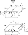
- FIG. 1 is a perspective view showing a dipole-anisotropic rare earth sintered magnet according to an embodiment of the present invention.
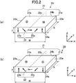
- 1 is a perspective view showing a tripolar anisotropic anisotropic rare earth sintered magnet according to an aspect of an embodiment of the present invention.
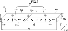
- FIG. FIG. 6 is a perspective view showing a tripolar anisotropic anisotropic rare earth sintered magnet according to another aspect of an embodiment of the present invention. It is a figure which shows an example of the surface magnetic flux density distribution obtained by the rare earth sintered magnet of the unipolar pole anisotropic shown in FIG.
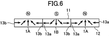
- FIG. It is a figure which shows the usage example of the rare earth sintered magnet shown in FIG. It is a figure which shows an example of the surface magnetic flux density distribution obtained by the rare earth sintered magnet of the bipolar pole anisotropic shown in FIG. It is a figure which shows the usage example of the rare earth sintered magnet shown in FIG. It is a figure which shows an example of the surface magnetic flux density distribution obtained by the rare earth sintered magnet of the tripolar pole anisotropic by the one aspect
- FIG. 1A is a perspective view showing the direction of the axis of a rare earth sintered magnet
- FIG. 2B is an EBSD analysis at the center and both ends of the magnet.
- (C) shows the orientation axis angle in the cross section of the magnet along the A2 axis in (a). It is a figure which shows a part of production
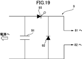
- FIG. 1 It is a perspective view in the edge part of the magnetic field application apparatus which can be used in order to manufacture the rare earth sintered magnet of the two poles anisotropic shown in FIG. It is sectional drawing of the magnetic field application apparatus shown in FIG. It is a figure which shows an example of the electric circuit which can be used in order to generate
- FIG. 1 It is sectional drawing of the magnetic field application apparatus which can be used in order to manufacture the rare earth sintered magnet of the unipolar anisotropic shown in FIG. It is a figure which shows the surface magnetic flux density distribution used in order to obtain
- Rare earth sintered magnet] 1 to 4 are conceptual diagrams showing various structural aspects of rare earth sintered magnets 1 to 4 according to an embodiment of the present invention.
- This direction can correspond to the magnetization direction of the magnet material particles, in other words, the same or substantially the same direction as the magnetization direction of the rare earth sintered magnet.
- the orientation axes in the same direction are formed on the opposite end face, that is, the end face 14b.
- FIG. 1 shows a practically useful surface magnetic flux density only on one surface 11 in the thickness direction “ ⁇ ” or mainly on one surface in the thickness direction.
- 1 is a perspective view showing a rare earth sintered magnet 1 which can generate a magnetic flux having only one polarity of one of N and S poles on one surface 11 thereof.
- 1 shows a rare earth sintered magnet 1A that produces substantially only an N pole on one surface 11, and
- FIG. 1 shows a substantial effect on one surface 11 in particular.
- 1 shows rare earth sintered magnets 1B that generate only the S pole.
- the substantial difference between the rare earth sintered magnet 1A and the rare earth sintered magnet 1B is only in that the polarities exhibited on the surface 11 are opposite, and the other points are substantially the same. You can think of it.
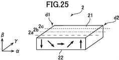
- FIG. 2 shows a practically useful surface magnetic flux density only on one surface 21 in the thickness direction “ ⁇ ” or mainly on one surface in the thickness direction.
- FIG. 2 is a perspective view showing a rare earth sintered magnet 2 that can generate a magnetic flux having one polarity and one polarity of N pole and S pole on the one surface 21;
- the N pole is generated on one side 21a and the S pole is generated on the other side 21b when viewed from the vertical surface 23c located at the center of the width direction “ ⁇ ” on one surface 21.
- the rare earth sintered magnet 2A to be used is shown in FIG. 2B.
- FIG. 2B shows a practically useful surface magnetic flux density only on one surface 21 in the thickness direction “ ⁇ ” or mainly on one surface in the thickness direction.
- FIG. 2 is a perspective view showing a rare earth sintered magnet 2 that can generate a magnetic flux having one polarity and one polarity of N pole and S pole on the one surface 21;
- the N pole is generated on one side 21a
- the S pole is provided on one side 21a as viewed from the vertical surface 23c located at the center of the width direction “ ⁇ ” on one side 21.
- each of the rare earth sintered magnets 2B for generating an N pole on the other side 21b is shown.
- the only substantial difference between the rare earth sintered magnet 2A and the rare earth sintered magnet 2B is that the polarity exhibited by the surface 21 is in the opposite direction, and the other points are substantially the same. You can think of it.
- 3 and 4 are tripolar polar anisotropic rare earth sintered magnets 3 and 4, more specifically, only on one surface 31, 41 in the thickness direction “ ⁇ ” or mainly on one surface in the thickness direction.
- a magnetic flux having a practically useful surface magnetic flux density can be generated, and on the one surface 31, 41, substantially “N pole, S pole, N pole” or “S pole, N pole, S pole”. It is a perspective view which shows the rare earth sintered magnets 3 and 4 which have these in this order.
- the rare earth sintered magnet 3 of FIG. 3 has, on one surface 31 thereof, an S pole at the center in the width direction “ ⁇ ”, and one side 31a and the other side as viewed from the vertical surface 33c located at the center. N poles are generated on each side 31b.
- the rare earth sintered magnet 4 of FIG. 4 has, on one surface 41, an N pole at the center in the width direction “ ⁇ ” and one side 41a when viewed from the vertical surface 43c positioned at the center. S poles are generated on the other side 41b.
- the magnetization is reversed and the surfaces 31 and 41 are exhibited. Magnets with opposite polarities can also be used.
- the rare earth sintered magnet 3 shown in FIG. 3 is obtained by bonding the rare earth sintered magnet 1A and the rare earth sintered magnet 1B shown in FIG. 1 to each other on their side surfaces, more specifically, shown in FIG. It can also be regarded as having substantially the same structure as the structure.
- the rare earth sintered magnet 4 shown in FIG. 4 is obtained by bonding the rare earth sintered magnet 2A and the rare earth sintered magnet 2B shown in FIG. 2 to each other on their side surfaces. It can also be viewed as having substantially the same configuration as part of the structure shown. Therefore, according to the rare earth sintered magnets 3 and 4 of FIG. 3 and FIG. 4, it is possible to obtain a magnet having a shape in which the rare earth sintered magnet 1 and the rare earth sintered magnet 2 are combined without any trouble.
- Each of the rare earth sintered magnets 1 to 4 shown in FIG. 1 to FIG. 4 is orthogonal to each other in the width direction (arrow “ ⁇ ” direction shown in the figure), the thickness direction (arrow “ ⁇ ” direction shown in the figure), and the length direction ( 3D shape having an arrow ( ⁇ direction) as shown. As shown in FIGS. 1 to 4, these may have a rectangular shape, for example. However, it is not always necessary to have a rectangular shape, and it is sufficient to include a three-dimensional shape that can define the width direction, the thickness direction, and the length direction. Therefore, for example, the surface in the width direction and the thickness direction may be arcuate or trapezoidal.
- width direction, thickness direction, and length direction refer to the orientation direction of the easy axis of magnetization, the surface (main surface) that can generate a magnetic flux having a practically useful surface magnetic flux density, and the opposite direction.
- the surface to be used it is merely for convenience. For example, the length relationship between them is not defined.
- the width dimension “W” in the width direction “ ⁇ ” of the rare earth sintered magnets 1 to 4 is preferably small within a practical range, and is 10 mm or more and 40 mm or less in consideration of the performance of a currently available magnetic field application device. 30 mm or less is preferable, 20 mm or less is more preferable, and 10 mm or less is still more preferable. If the width dimension “W” is too small or too large, depending on the currently available magnetic field application devices, a sufficient magnetic field cannot be applied to the sintered body for the rare earth sintered magnet. In order to obtain a desired surface magnetic flux density by magnetization, it is preferable to limit the width dimension in the width direction to a certain size.
- the thickness dimension “t” in the thickness direction “ ⁇ ” is preferably small within a practical range. By reducing the thickness dimension, the size and weight of the magnet unit can be reduced. However, if the thickness dimension is too small, a sufficient surface magnetic flux density cannot be generated, so that it is necessary to be at least 1 mm. On the other hand, if the thickness dimension is too large, a sufficient magnetic field cannot be applied to the sintered body for a rare earth sintered magnet. In order to magnetize, it is thought that it is necessary to be 12 mm or less, 10 mm or less is preferable, 8 mm or less is more preferable, 6 mm or less is more preferable, and 4 mm or less is still more preferable.
- the thickness dimension in the thickness direction is preferably limited to a certain size.
- the length dimension “K” in the length direction “ ⁇ ” can be determined relatively freely, it is preferably 5 mm to 100 mm, and more preferably 5 mm to 100 mm considering the performance of currently available magnetic field application devices. It is 50 mm, more preferably 5 mm to 40 mm.
- FIG. 5 shows an example of the surface magnetic flux density distribution obtained by the unipolar anisotropic rare earth sintered magnet 1 shown in FIG.
- the horizontal axis represents the distance (mm) from the vertical surface 13c located at the center of the rare earth sintered magnet 1 in the width direction “ ⁇ ”, and the vertical axis represents the surface magnetic flux density (mT) at this position.
- the solid line shows the surface magnetic flux density distribution measured at a position away from the one surface 11 by a predetermined distance, for example, 1 mm, in the thickness direction “ ⁇ ” in the direction opposite to the other surface 12
- a broken line indicates a surface magnetic flux density distribution measured at a position away from the other surface 12 by a predetermined distance, for example, 1 mm, in the thickness direction “ ⁇ ” in the opposite direction to the one surface 11.
- the surface magnetic flux density distribution is set to have a substantially symmetrical shape by adjusting the orientation direction of the easy magnetization axis.
- the rare earth sintered magnet 1A shown in FIG. 1A has a predetermined polarity at the central portion (13c) in the width direction “ ⁇ ” on one surface 11;
- a magnetic flux having the maximum surface magnetic flux density (hereinafter referred to as the maximum surface magnetic flux density) D1 of the N pole is generated, and opposite in the vicinity of the side surfaces 13a and 13b located at both ends in the width direction “ ⁇ ”.
- the other surface 12 generates magnetic fluxes having maximum surface magnetic flux densities D2a and D2b having small S poles at positions closer to the side surfaces 13a and 13b than the central portion (13c) in the width direction “ ⁇ ”.
- the magnetic flux having a relatively large surface magnetic flux density D4a, D4b of the S pole is generated at a position further closer to the side surfaces 13a, 13b.
- the rare earth sintered magnet 1 has a central portion (in particular, the central portion ( ⁇ ) in the width direction “ ⁇ ” only on one surface 11 in the thickness direction “ ⁇ ” or mainly on one surface in the thickness direction. In the vicinity of 13c), a magnetic flux having a practically useful surface magnetic flux density is generated.
- the plurality of rare earth sintered magnets 1A and 1B can be brought into contact with each other without substantially repelling the magnetic force. It can also be arranged alternately in the butted state. Thereby, it is possible to easily configure a magnet arrangement in which N poles and S poles are alternately arranged on one surface 11.
- FIG. 7 shows an example of the surface magnetic flux density distribution obtained by the rare earth sintered magnet 2 anisotropic to the two poles shown in FIG.
- the surface magnetic flux density was measured by the same method as in FIG.
- the surface magnetic flux density distribution is set to have a substantially symmetrical shape by adjusting the orientation direction of the easy magnetization axis.
- the surface magnetic flux density is almost zero at the central portion (23c) in the width direction “ ⁇ ” on one surface 21 thereof, and the one surface 21 thereof.
- the other surface 22 generates magnetic fluxes having the maximum surface magnetic flux densities D2a and D2b having the opposite polarity to the one surface 21 at the same position as the one surface 21 in the width direction “ ⁇ ”.
- the maximum surface magnetic flux densities D2a and D2b are much smaller than the maximum surface magnetic flux densities D1a and D1b, and do not cause a leakage magnetic flux that causes a problem.
- the rare earth sintered magnet 2 has a central portion (in particular, the central portion ( ⁇ ) in the width direction “ ⁇ ” only on one surface 21 in the thickness direction “ ⁇ ” or mainly on one surface in the thickness direction.
- the magnetic flux having a practically useful surface magnetic flux density is generated at a position closer to one side surface 23a or the other side surface 23b than 23c).
- the magnetic forces generated on the side surfaces 23a and 23b located at both ends in the width direction “ ⁇ ” cause some repulsion to each other, but the forces are weak. Therefore, as shown in FIG.
- the sintered magnets 2A and 2B can be alternately arranged with their side surfaces 23a and 23b butting each other. As a result, a magnet array in which the N pole and the S pole are alternately arranged on one surface 21 can be configured.
- FIGS. 9 and 10 show examples of surface magnetic flux density distributions obtained by the tripolar anisotropic anisotropic rare earth sintered magnets 3 and 4 shown in FIGS. 3 and 4, respectively.
- the surface magnetic flux density was measured by the same method as in FIG.
- the surface magnetic flux density distribution is set to have a substantially symmetrical shape by adjusting the orientation direction of the easy magnetization axis.
- a predetermined polarity in this case, an S pole, is formed at the central portion (33 c) in the width direction “ ⁇ ” on one surface 31.
- the magnetic flux having the maximum surface magnetic flux density D1c is generated, and one side 31a of the one surface 31 has a predetermined polarity, in this case, at a position close to the one side surface 33a in the width direction “ ⁇ ”.
- An N-pole magnetic flux having the maximum surface magnetic flux D1a is generated, and on the other side 31b of the one surface 31, the one side 31a is located at a position close to the other side surface 33b in the width direction “ ⁇ ”.
- a magnetic flux having the same polarity, that is, N pole and having a maximum surface magnetic flux density D1b is generated.
- the other surface 32 is at the same position as the one surface 31 in the width direction “ ⁇ ”, and the one surface has the same polarity as the maximum surface magnetic flux density D2a, D2b, here, a magnetic flux having a value of approximately zero.
- these maximum surface magnetic flux densities D2a and D2b are very small compared to the maximum surface magnetic flux densities D1a and D1b, and do not cause a leakage magnetic flux that causes a problem.
- the rare-earth sintered magnets 3 and 4 are formed only on one surface 31, 41 in the thickness direction “ ⁇ ” or mainly on one surface in the thickness direction. ”And a practically useful surface at a position closer to one side surface 33a, 43a or the other side surface 33b, 43b than the central portion (33c, 43c) in the width direction“ ⁇ ”. A magnetic flux having a magnetic flux density is generated.
- the rare earth sintered magnets 3 and 4 shown in FIGS. 3 and 4 also have their side surfaces 33a and 33b or the side surfaces 43a and 43b abutted with each other. Can be arranged alternately. Thereby, it is possible to configure a magnet arrangement in which N poles and S poles are alternately arranged on one surface 31, 41.
- any of the rare earth sintered magnets 1 to 4 shown in FIGS. 1 to 4 is practically useful only on one side in the thickness direction “ ⁇ ” or mainly on one side in the thickness direction. Since a magnetic flux having a surface magnetic flux density is generated, it is not necessary to provide a large amount of magnet material on the other surface, and it is not necessary to provide a yoke to capture leakage magnetic flux leaking from the magnetic circuit, or a small amount As a result, these rare earth sintered magnets 1 to 4 are reduced in size and weight.
- the rare earth sintered magnets 1 to 4 shown in FIGS. 1 to 4 magnetize a sintered body for the rare earth sintered magnets 1 to 4 (hereinafter referred to as “sintered body for rare earth sintered magnet”). can get.
- the magnetization process does not substantially change the shape and size of the sintered body for rare earth sintered magnet.
- the sintered body for a rare earth sintered magnet is similar to the rare earth sintered magnets 1 to 4 in the width direction (arrow “ ⁇ ” direction in the figure), the thickness direction (arrow “ ⁇ ” direction in the figure), and the length direction ( It may be considered to have a three-dimensional shape having a direction indicated by an arrow “ ⁇ ” (shown) and a shape corresponding to the rare earth sintered magnets 1 to 4, for example, a rectangular shape as shown in FIGS.
- the size of the sintered body for the rare earth sintered magnet may be considered to be substantially the same as that of the rare earth sintered magnets 1 to 4. Since the body may be slightly polished for leveling, it may have a slightly different size.
- the rare earth magnet forming material from which the sintered body for rare earth sintered magnet is based includes a magnet material containing a rare earth substance.
- a magnet material containing a rare earth substance for example, an Nd—Fe—B based magnet material can be used.
- the Nd—Fe—B based magnet material is, for example, R in weight percentage (R is one or more of rare earth elements including Y) 27.0 to 40.0 wt%, more preferably It may contain 27.0 to 35 wt%, B to 0.6 to 2 wt%, more preferably 0.6 to 1.1 wt%, and Fe as electrolytic iron in a proportion of 60 to 75 wt%.
- the Nd—Fe—B based magnet material contains 27 to 40 wt% Nd, 0.8 to 2 wt% B, and 60 to 70 wt% Fe.
- This magnet material has Dy, Tb, Co, Cu, Al, Si, Ga, Nb, V, Pr, Mo, Zr, Ta, Ti, W, Ag, Bi, Zn, Mg for the purpose of improving magnetic properties.
- a small amount of other elements such as may be included.
- the magnet material is included in the state of fine magnet material particles in the rare earth magnet forming material.
- the rare earth sintered magnets 1 to 4 and the sintered body for rare earth sintered magnet have a configuration in which these magnet material particles are integrally sintered, that is, the magnet material particles are located at any position of the magnet or sintered body. It has a configuration in which the magnets and the sintered body are joined to each other with a specific coupling structure. Therefore, for example, a piece having a desired shape is cut out from the magnet or the sintered body, and a plurality of the cut pieces are joined together. It has a different structure from the magnet and the sintered body for magnet formation.
- Each of the magnet material particles has an easy magnetization axis oriented in a predetermined direction as indicated by an arrow in FIGS.
- These easy magnetization axes are within the plane formed by the “ ⁇ direction” and “ ⁇ direction” in FIGS. 1 to 4, for example, flat front end surfaces 14a, 24a, 34a, 44a, and rear end surface 14b, In each of the planes 24b, 34b, and 44b, they are generally oriented in a predetermined direction indicated by an arrow shown. Furthermore, these easy magnetization axes are oriented in the directions indicated by the arrows in the respective cross sections in the “ ⁇ - ⁇ ” direction orthogonal to the length direction “ ⁇ ”.
- the magnetization direction in the rare earth sintered magnet 1 of FIG. 1 caused by the magnetization is the both ends (13a, 13b) in the width direction “ ⁇ ” and the center portion (13c) in the width direction “ ⁇ ”. However, it is different from 90 ° ⁇ 5 °, and it is not clear from the drawing, but from both end portions (13a, 13b) in the width direction “ ⁇ ” toward the central portion (13c) in the width direction “ ⁇ ”. It gradually changes in the area.
- ⁇ 5 ° is taken into account that some errors may occur depending on the measurement conditions and magnetic field application method. Is not significantly affected (the same applies hereinafter).
- the orientation direction of the easy magnetization axis in the sintered body for rare earth sintered magnet before magnetizing the rare earth sintered magnet 2 in FIG. 2 more specifically, the direction substantially along such orientation direction. 2, the magnetization direction in the rare earth sintered magnet 2 of FIG.
- the easy magnetization axis is not usually polar, it becomes a vector having polarity by magnetizing magnetic material particles. Therefore, in FIGS. 1 to 4, the polarity to be magnetized is taken into consideration. In addition, an arrow in which directivity is given to the easy magnetization axis is shown. That is, in this specification, the term “orientation direction of the easy axis” or a similar term is used to represent the direction in consideration of the polarity to be magnetized in this way.
- the orientation angle means an angle in the direction of the orientation axis of the easy axis of magnetization of the magnetic material particles with respect to a predetermined reference line.
- the section for determining the orientation axis angle is a quadrangular section including at least 30, for example, 200 to 300 magnet material particles, or a square section having a side of 35 ⁇ m.
- Orientation axis angle is an angle between these orientation axes represented by arrows shown in FIGS. 1 to 4 and one reference line.
- the reference line can be set arbitrarily.
- FIG. 11 is a schematic enlarged view showing a procedure for determining the “orientation angle” and the “orientation axis angle” of the easy magnetization axis of each magnetic material particle.
- the quadrangular section R includes a large number of magnet material particles P such as 30 or more, for example, 200 to 300. As the number of magnet material particles included in the quadrangular section increases, the measurement accuracy increases, but even about 30 particles can be measured with sufficient accuracy.
- Each magnet material particle P has an easy axis P-1.
- the easy magnetization axis P-1 of each magnetic material particle P has an “orientation angle” that is an angle between a direction in which the easy magnetization axis is directed and a reference line. Then, among the “orientation angles” of the easy magnetization axes P-1 of the magnet material particles P in the quadrangular section R shown in FIG. 11, the most frequent orientation angle is defined as an “orientation axis angle” B.
- the direction determined by the “orientation axis angle” is defined as the “orientation direction of the easy axis of magnetization”. This direction substantially corresponds to the magnetization direction of the magnet material particles and the “direction of magnetization” and “orientation direction of the easy axis of magnetization” in the rare earth sintered magnets 1 to 4.
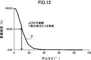
- FIG. 12 is a chart showing a procedure for obtaining the orientation angle variation angle.
- the distribution of the difference ⁇ in the orientation angle of the easy magnetization axes of the individual magnet material particles with respect to the easy magnetization axis is represented by a curve C.
- the position at which the cumulative frequency shown on the vertical axis is maximum is 100%, and the value of the orientation angle difference ⁇ at which the cumulative frequency is 50% is the half width.
- the orientation angle of the easy magnetization axis P-1 in each magnetic material particle P can be obtained by an “electron backscattering diffraction analysis method” (EBSD analysis method) based on a scanning electron microscope (SEM) image.
- EBSD analysis method based on a scanning electron microscope (SEM) image.
- SEM scanning electron microscope
- EBSD detection method AZtecHKL EBSD Nordlys Nano Integrated
- JSM-70001F manufactured by JEOL Ltd., Akishima City, Tokyo, or EDAX.
- SUPER40VP manufactured by ZEISS which is a scanning electron microscope equipped with an EBSD detector manufactured by KK (Hikari High Speed EBSD Detector).
- FIG. 13 shows an example of the orientation display of the easy axis by the EBSD analysis method.
- FIG. 13A is a perspective view showing the direction of the axis of the rare earth sintered magnet, and FIG.
- FIG. 13C shows the orientation axis angle in the cross section of the magnet along the A2 axis.
- the orientation axis angle can be displayed by dividing the orientation vector of the easy magnetization axis of the magnetic material particle into a component in a plane including the A1 axis and the A2 axis and a component in a plane including the A1 axis and the A3 axis.
- the A2 axis is the width direction
- the A1 axis is the thickness direction.
- the center diagram of FIG. 13B shows that the orientation of the easy axis is substantially in the direction along the A1 axis at the center in the width direction of the magnet.
- FIG. 13B shows that the orientation of the easy axis of magnetization at the left end in the width direction of the magnet is inclined from the bottom to the top right along the plane of the A1 axis-A2 axis. Show.
- the diagram on the right side of FIG. 13B shows that the orientation of the easy axis at the right end in the width direction of the magnet is inclined from the bottom to the top left along the plane of the A1 axis-A2 axis.
- FIG. 13C Such an orientation is shown in FIG. 13C as an orientation vector.
- the pole figure shown in FIG. 13B is a pole figure obtained by a SUPRA 40VP manufactured by ZEISS, which is a scanning electron microscope provided with an EBSD detector manufactured by EDAX (Hikari High Speed EBSD Detector).
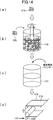
- FIG. 14 shows a part of the production process of the rare earth magnet forming material.
- an ingot of a magnet material made of an Nd—Fe—B alloy having a predetermined fraction is manufactured by a casting method.
- an Nd—Fe—B alloy used in a neodymium magnet has a composition containing Nd of 30 wt%, preferably iron containing 67 wt% and B of 1.0 wt%.
- this ingot is roughly pulverized to a size of about 200 ⁇ m using a known means such as a stamp mill or a crusher.
- the ingot can be melted, flakes can be produced by strip casting, and coarsely pulverized by hydrogen cracking. Thereby, coarsely pulverized magnet material particles 115 are obtained (see FIG. 14A).
- the coarsely pulverized magnet material particles 115 are finely pulverized by a wet method using a bead mill 116 or a dry method using a jet mill.
- the coarsely pulverized magnet particles 115 are finely pulverized in a solvent to a predetermined particle size, for example, 0.1 ⁇ m to 5.0 ⁇ m, and the magnet material particles are dispersed in the solvent (See FIG. 14B).
- the magnet particles contained in the solvent after the wet pulverization are dried by means such as drying under reduced pressure, and the dried magnet particles are taken out (not shown).
- the type of solvent used for grinding is not particularly limited, alcohols such as isopropyl alcohol, ethanol and methanol, esters such as ethyl acetate, lower hydrocarbons such as pentane and hexane, benzene, toluene, xylene and the like.
- Organic solvents such as aromatics, ketones and mixtures thereof, or inorganic solvents such as liquefied nitrogen, liquefied helium, and liquefied argon can be used. In this case, it is preferable to use a solvent containing no oxygen atom in the solvent.
- the coarsely pulverized magnet material particles 115 are subjected to (a) nitrogen gas having an oxygen content of 0.5% or less, preferably substantially 0%, Ar gas, Jet mill in an atmosphere composed of an inert gas such as He gas, or (b) an atmosphere composed of an inert gas such as nitrogen gas, Ar gas or He gas having an oxygen content of 0.0001 to 0.5% To obtain fine particles having an average particle diameter in a predetermined range of 6.0 ⁇ m or less, for example, 0.7 ⁇ m to 5.0 ⁇ m.
- the oxygen concentration being substantially 0% is not limited to the case where the oxygen concentration is completely 0%, but contains oxygen in such an amount as to form an oxide film very slightly on the surface of the fine powder. Means that it may be. If hydrogen remains in the magnetic powder, the organic component is altered, so it is preferable to remove hydrogen from the finely pulverized magnetic powder.
- the temperature may be raised, for example, from room temperature to 120 ° C. or higher for 0.5 hours, and then the temperature may be maintained for a predetermined time, for example, 1 hour or more.
- the magnet material particles finely pulverized by the bead mill 116 or the like are formed into a desired shape.
- a mixture obtained by mixing the finely pulverized magnet material particles and the binder made of the resin material as described above, that is, a composite material is prepared.
- the resin used as the binder is preferably a depolymerizable polymer that does not contain an oxygen atom in the structure.
- the composite material of the magnet particles and the binder can be reused for the remainder of the composite material generated when the composite material is formed into a desired shape, and the composite material is heated and softened. It is preferable to use a thermoplastic resin as the resin material so that the magnetic field orientation can be performed.
- a polymer composed of one or two or more polymers or copolymers formed from the monomer represented by the following general formula (1) is preferably used.
- R 1 and R 2 represent a hydrogen atom, a lower alkyl group, a phenyl group or a vinyl group.
- polystyrene-butadiene block copolymer which is a copolymer of styrene and isoprene (SIS), butyl rubber (IIR) which is a copolymer of isobutylene and isoprene, styrene-butadiene block copolymer (SBS) which is a copolymer of styrene and butad
- Ethylene-butadiene-styrene Copolymer SEBS
- SEPS styrene-ethylene-propylene-styrene copolymer
- EPM ethylene-propylene copolymer
- EPDM obtained by copolymerization of a diene monomer with ethylene and propylene
- 2-methyl-1-pentene polymer resin that is a polymer of 2-methyl-1-pentene
- 2 polymer that is 2-methyl-1-butene -Methyl-1-butene polymer resin PEBS
- SEPS styrene-ethylene-propylene-styrene copolymer
- EPM ethylene-propylene copolymer
- the resin used for the binder may include a small amount of a polymer or copolymer of a monomer containing an oxygen atom or a nitrogen atom (for example, polybutyl methacrylate, polymethyl methacrylate, etc.). Furthermore, a monomer that does not correspond to the general formula (1) may be partially copolymerized. Even in that case, the object of the present invention can be achieved.
- thermoplastic resin that softens at 250 ° C. or lower in order to appropriately perform magnetic field orientation, more specifically, a thermoplastic resin having a glass transition point or a flow start temperature of 250 ° C. or lower is used. It is desirable.
- an alignment lubricant As the alignment lubricant, alcohol, carboxylic acid, ketone, ether, ester, amine, imine, imide, amide, cyan, phosphorus functional group, sulfonic acid, compound having unsaturated bond such as double bond and triple bond, It is desirable to add at least one of the liquid saturated hydrocarbon compounds. A mixture of a plurality of these substances may be used. As will be described later, when applying a magnetic field to a mixture of magnet material particles and a binder, that is, a composite material to magnetically orient the magnet material, the mixture is heated so that the binder component is softened and magnetic field orientation is performed. Process.
- the amount of carbon remaining in the sintered body after sintering can be 2000 ppm or less, more preferably 1000 ppm or less.
- the amount of oxygen remaining in the sintered body after sintering can be 5000 ppm or less, more preferably 2000 ppm or less.
- the amount of the binder added is an amount that can appropriately fill the gaps between the magnetic material particles so as to improve the thickness accuracy of the molded product obtained as a result of molding when molding a slurry or a heat-melted composite material.
- the ratio of the binder to the total amount of the magnetic material particles and the binder is 1 wt% to 40 wt%, more preferably 2 wt% to 30 wt%, still more preferably 3 wt% to 20 wt%, and particularly preferably 5 wt% to 15 wt%. .
- the ratio of the resin to the total amount of the resin used for the binder and the magnetic material particles is preferably 1 wt% to 30 wt%, more preferably 2 wt% to 20 wt%, still more preferably 3 wt% to 15 wt%, and particularly preferably 3.5 wt% to 12 wt%.
- a mixture of magnetic material particles and a binder that is, a composite material 117 is once formed into a sheet-shaped green molded body (hereinafter referred to as “green sheet”), and then a molded body shape for orientation treatment is used.
- the composite material is particularly formed into a sheet shape, for example, by heating the composite material 117 that is a mixture of magnet material particles and a binder and then forming into a sheet shape, or by combining the magnet material particles and the binder
- a method in which the composite material 117 which is a mixture is placed in a mold and heated and pressed by a method in which the composite material is molded by extrusion using an extrusion molding machine, or by including magnetic material particles, a binder, and an organic solvent Forming by slurry coating or the like that forms a sheet by coating the slurry on the substrate can be employed.
- the molding may be performed by putting the composite material 117 in a molding die and pressurizing to a pressure of 0.1 to 100 MPa while heating to room temperature to 300 ° C.
- a method in which the composite material 117 heated to a softening temperature is pressed and filled into a mold by applying an injection pressure is possible to employ a method in which the composite material 117 heated to a softening temperature is pressed and filled into a mold by applying an injection pressure.
- a binder As already described, by mixing a binder with magnetic material particles finely pulverized by a bead mill 116 or the like, a clay-like mixture composed of magnet material particles and a binder, that is, a composite material 117 is produced.
- a binder as described above, a mixture of a resin and an alignment lubricant can be used.
- the resin it is preferable to use a thermoplastic resin that does not contain an oxygen atom in the structure and is made of a depolymerizable polymer.
- the alignment lubricant alcohol, carboxylic acid, ketone, ether, It is preferable to add at least one of an ester, amine, imine, imide, amide, cyan, phosphorus functional group, sulfonic acid, and a compound having an unsaturated bond such as a double bond or a triple bond.
- a compound having an unsaturated bond examples include a compound having a double bond and a compound having a triple bond, and in particular, the effect of reducing cracks in the sintered body. From the viewpoint that can be expected, a compound having a triple bond is more preferable.
- the compound having a triple bond it is preferable to use a compound that can be easily removed in a calcining process described later.
- the compound used preferably has no hetero atom, and is a hydrocarbon.
- Particularly preferred is a compound composed solely of
- the compound having a triple bond is preferably a compound having a triple bond at the terminal.
- the number of carbons as its constituent elements is preferably 10 or more, and more preferably 14 or more, in order to facilitate handling by increasing the boiling point. 16 or more, more preferably 18 or more.
- the upper limit of carbon number is not specifically limited, For example, it can be 30 or less.
- a compound having a functional group having a hetero atom is used in order to be able to interact more strongly with the surface of the magnetic material particles and to exert a high orientation lubricating effect. It is preferable to use a compound having a functional group having a hetero atom at the terminal.
- the number of carbon atoms in the compound having a double bond is preferably 6 or more, more preferably 10 or more, still more preferably 12 or more, and particularly preferably 14 or more. Although the upper limit of carbon number is not specifically limited, For example, it can be 30 or less.
- the above compound having a triple bond and the above compound having a double bond may be used in combination.
- the amount of the binder added is such that the ratio of the binder to the total amount of the magnetic material particles and the binder in the composite material 117 after the addition is 1 wt% to 40 wt%, more preferably 2 wt% to 30 wt%. Is 3 wt% to 20 wt%, particularly preferably 5 wt% to 15 wt%.
- the ratio of the resin to the total amount of the resin used for the binder and the magnetic material particles is preferably 1 wt% to 30 wt%, more preferably 2 wt% to 20 wt%, still more preferably 3 wt% to 15 wt%, and particularly preferably 3.5 wt% to 12 wt%.
- the addition amount of the oriented lubricant is preferably determined according to the particle size of the magnet material particles, and it is recommended that the addition amount be increased as the particle size of the magnet material particles is smaller.
- the specific addition amount is 0.01 to 20 parts by weight, more preferably 0.3 to 10 parts by weight, still more preferably 0.5 to 5 parts by weight with respect to 100 parts by weight of the magnetic material particles. Part by weight, particularly preferably 0.8 to 3 parts by weight.
- the addition amount is small, the dispersion effect is small and the orientation may be lowered.
- there is too much addition amount there exists a possibility of contaminating a magnet material particle.
- the orientation lubricant added to the magnet material particles adheres to the surface of the magnet material particles, disperses the magnet material particles, gives a clay-like mixture, and rotates the magnet material particles in the orientation process in the magnetic field described later. Acts to assist. As a result, orientation is easily performed when a magnetic field is applied, and the easy magnetization axis directions of the magnet particles can be aligned in substantially the same direction, that is, the degree of orientation can be increased. In particular, when a binder is mixed with magnetic material particles, the binder is present on the surface of the particles, which increases the frictional force during magnetic field alignment treatment, which may reduce the orientation of the particles. The effect of adding more increases.
- the mixing of the magnet material particles and the binder is preferably performed in an atmosphere made of an inert gas such as nitrogen gas, Ar gas, or He gas.
- the mixing of the magnet material particles and the binder is performed, for example, by putting the magnet material particles and the binder into a stirrer and stirring with the stirrer. In this case, heating and stirring may be performed to promote kneading properties.
- the binder is added to the solvent and kneaded without taking out the magnet particles from the solvent used for pulverization, and then the solvent is volatilized. May be obtained.
- the green sheet described above is created by forming the composite material 117 into a sheet shape.
- the composite material 117 is heated to melt the composite material 117 so as to have fluidity, and then applied onto the support substrate 118. Thereafter, the composite material 117 is solidified by heat radiation, and a long sheet-like green sheet 119 is formed on the support base 118 (see FIG. 14D).
- the temperature at which the composite material 117 is heated and melted varies depending on the type and amount of the binder used, but is usually 50 ° C. to 300 ° C. However, the temperature needs to be higher than the flow start temperature of the binder to be used.
- slurry coating When slurry coating is used, magnetic material particles, a binder, and optionally an alignment lubricant that promotes alignment are dispersed in a large amount of solvent, and the slurry is coated on the support substrate 118. Work. Thereafter, the long sheet-like green sheet 119 is formed on the support substrate 118 by drying and volatilizing the solvent.
- the die method and the comma coating method are particularly excellent in layer thickness controllability, that is, a method capable of applying a high-accuracy thickness layer to the surface of the substrate.
- the composite material 117 heated and fluidized is pumped by a gear pump, injected into the die, and discharged from the die for coating.
- the composite material 117 is fed into the nip gap between two heated rolls in a controlled amount, and the composite material 117 melted by the heat of the roll on the support substrate 118 while rotating the roll.
- a silicone-treated polyester film is preferably used as the support substrate 118.
- the composite material 117 melted by extrusion molding or injection molding is extruded on the support substrate 118 while being molded into a sheet shape, thereby forming a green on the support substrate 118.
- the sheet 119 can also be formed.
- the composite material 117 is applied using the slot die 120.
- the sheet thickness of the green sheet 119 after coating is measured, and the nip between the slot die 120 and the support substrate 118 is controlled by feedback control based on the measured value. It is desirable to adjust the gap. In this case, it is possible to reduce the fluctuation of the amount of the fluid composite material 117 supplied to the slot die 120 as much as possible, for example, to suppress the fluctuation to ⁇ 0.1% or less, and also to reduce the fluctuation of the coating speed as much as possible. For example, it is desirable to suppress fluctuations of ⁇ 0.1% or less. By such control, it is possible to improve the thickness accuracy of the green sheet 119.
- the thickness accuracy of the formed green sheet 119 is preferably within ⁇ 10%, more preferably within ⁇ 3%, and even more preferably within ⁇ 1% with respect to a design value such as 1 mm.
- a design value such as 1 mm.
- the thickness of the green sheet 119 is preferably set in the range of 0.05 mm to 20 mm. If the thickness is less than 0.05 mm, it is necessary to carry out multilayer lamination in order to achieve the necessary magnet thickness, so that productivity is lowered.
- a processing sheet piece cut out to a size corresponding to a desired magnet size is created from the green sheet 119 formed on the support substrate 118 by the hot melt coating described above. Since the processing sheet piece is filled in a sintering mold later and is a source of a rare earth sintered magnet, it can be regarded as an example of a rare earth magnet forming material. Further, since the green sheet 119 is a material of the processing sheet piece and is a source of the rare earth sintered magnet, it is of course included in the concept of the rare earth magnet forming material. Furthermore, as will be described later, not only the molded body manufactured by the green sheet method described above, but also a molded body manufactured by the compacting method can be used as the rare earth magnet forming material, for example. This point will be described later.
- the shape is a shape that takes into account the rare-earth sintered magnets 1 to 4 that are the final product, and the actual size to be cut out is the size in the pressing direction in the sintering process. Is determined so that a predetermined magnet size can be obtained after the sintering process. As will be described later, since the sintering process is performed by pressure sintering, the processing sheet piece is contracted in the pressing direction (the length direction “ ⁇ ” in FIGS. 1 to 4).
- the difference between the rare-earth sintered magnets 1 to 4 that are the final product and the processing sheet piece is that of the rare-earth sintered magnets 1 to 4 that are the final product.
- the length along the pressing direction “ ⁇ ” only shrinks to about half of the length of the processing sheet piece in the same direction “ ⁇ ”. Since the rare earth sintered magnets 1 to 4 are obtained by magnetizing a sintered sheet piece, the sintered body obtained by sintering the processing sheet piece is also a rare earth sintered magnet 1. It may be considered that it has the same shape and dimensions as 4 to 4.
- the surface temperature (hereinafter referred to as “orientation temperature”) of the processing sheet piece after application of the magnetic field is 50 ° C. to 150 ° C., preferably 60 ° C. to 120 ° C.
- the temperature and time for heating the processing sheet piece vary depending on the type and amount of the binder used, but are, for example, 40 to 250 ° C. and 0.1 to 60 minutes. In any case, in order to soften the binder in the processing sheet piece, the heating temperature needs to be higher than the glass transition point or the flow start temperature of the binder used.
- a means for heating the processing sheet piece for example, there is a system using a hot plate or a heat medium such as silicone oil as a heat source.
- the strength of the magnetic field in the application of the magnetic field can be 5000 [Oe] to 150,000 [Oe], preferably 10,000 [Oe] to 120,000 [Oe], and particularly preferably 25000 [Oe] to 70000 [Oe]. .
- the easy axis of magnetization of the crystal of the magnet material particles contained in the processing sheet piece is oriented in the direction along the magnetic field.
- a configuration in which a magnetic field is simultaneously applied to a plurality of processing sheet pieces may be employed.
- a mold having a plurality of cavities is used, or a plurality of molds are arranged and a magnetic field is applied simultaneously.
- the step of applying a magnetic field to the processing sheet piece may be performed simultaneously with the heating step, or may be performed after the heating step and before the binder of the processing sheet piece is solidified.
- the processed sheet piece after orientation in which the easy axis of magnetization is oriented is subjected to atmospheric pressure or a pressure higher or lower than atmospheric pressure, for example, 0.1 MPa to 70 MPa, preferably 1.0 Pa.
- the calcination treatment is performed by holding at the binder decomposition temperature for at least 2 hours or more, preferably several hours to several tens hours, for example, 5 hours.
- the amount of hydrogen supplied during the calcination is 2 to 6 L / min, for example, 5 L / min.
- the binder in other words, the organic compound contained in the composite in which the magnet material particles are mixed with the thermoplastic resin is decomposed into monomers by a depolymerization reaction or other reaction, and then dispersed and removed. It becomes possible. That is, a decarbonization process, which is a process for reducing the amount of carbon remaining in the processing sheet piece, is performed. Further, the calcination treatment is desirably performed under the condition that the amount of carbon remaining in the processing sheet piece is 2000 ppm or less, more preferably 1000 ppm or less.
- the entire processing sheet piece can be densely sintered by the subsequent sintering treatment, and the decrease in residual magnetic flux density and coercive force can be suppressed.
- a pressure shall be 15 Mpa or less.
- the pressurizing condition is a pressure higher than the atmospheric pressure, more specifically 0.2 MPa or more, the effect of reducing the residual carbon amount can be expected.
- the temperature of the calcining treatment may be 250 ° C. to 600 ° C., more preferably 300 ° C. to 550 ° C., for example 450 ° C., depending on the type of binder.
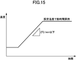
- a preferable result can be obtained by setting the temperature rising rate to 2 ° C./min or less, for example, 1.5 ° C./min. Therefore, when performing the calcination treatment, as shown in FIG. 15, the temperature is increased at a predetermined temperature increase rate of 2 ° C./min or less, and after reaching a preset temperature, that is, a binder decomposition temperature, The calcination treatment is performed by maintaining the set temperature for several hours to several tens of hours.
- the carbon in the processing sheet piece is not removed rapidly, but is removed step by step. It becomes possible to increase the density of the sintered body for forming a permanent magnet after sintering by reducing the amount of carbon. That is, by reducing the amount of residual carbon, the voids in the permanent magnet can be reduced.
- the rate of temperature rise is about 2 ° C./min
- the density of the sintered body for forming a permanent magnet after sintering can be 98% or more, for example, 7.40 g / cm 3 or more, It can be expected to achieve high magnet characteristics in the magnet after magnetization.
- a deoiling treatment for volatilizing oil components such as an alignment lubricant and a plasticizer may be performed.
- the temperature of the deoiling treatment may be 60 ° C. to 120 ° C., more preferably 80 ° C. to 100 ° C., depending on the type of oil component contained.
- a preferable result can be obtained by setting the temperature rising rate to 5 ° C./min or less, for example, 0.7 ° C./min.
- a more preferable result is obtained by performing the oil removal step in a reduced pressure atmosphere, and it is preferable to perform it under a reduced pressure of 0.01 Pa to 20 Pa, more preferably 0.1 Pa to 10 Pa. Note that the magnetic characteristics of the rare earth sintered magnet as the final product do not change depending on whether or not the oil removal treatment is performed.
- FIG. 16 the outline of the heat processing performed at a sintering process is shown.
- the horizontal axis represents time, and the vertical axis represents temperature (° C.).
- the sintering process includes a high-temperature heat treatment “B” (heat treatment 1) performed thereafter and a low-temperature heat treatment “C” (heat treatment 2) performed thereafter.
- the characteristics of the sintered body obtained through the sintering process “A” and the rare-earth sintered magnet that is the final product especially by performing the high-temperature heat treatment “B”. Can be significantly improved.
- the high-temperature heat treatment “B” and the low-temperature heat treatment “C” will be described as part of the sintering process. As will be apparent from the following description, these treatments are merely heat treatments, and the sintering treatment “ This is different from the pressure sintering in “A”.
- the sintering step is performed in a state where the processing sheet pieces are filled in a sintering mold (not shown) consisting of a pair of male and female molds prepared in advance.
- the sintering mold includes a cavity having a shape corresponding to the rare earth sintered magnet as the final product, for example, a cavity having a cross section corresponding to the processing sheet.
- the easy axis of the processing sheet piece is oriented in one plane, that is, formed by the width direction “ ⁇ ” and the thickness direction “ ⁇ ” in FIGS. In an aligned plane.
- ⁇ Sintering process> In the sintering process “A”, the calcined processing sheet piece is sandwiched between a male mold and a female mold and subjected to press pressure to be heated and fired while applying pressure. Bonding, that is, pressure sintering.
- the pressing direction is a direction (length direction “ ⁇ ” in FIGS. 1 to 4) orthogonal to the orientation direction of the easy axis of the processing sheet piece (the arrow direction in FIGS. 1 to 4). By applying pressure in this direction, it is possible to suppress the change in the orientation of the easy axis of magnetization given to the magnet material particles, and a sintered body with higher orientation can be obtained.
- the initial load when sandwiched between the male mold and the female mold is set to a relatively small constant pressure such as 0.5 MPa (the initial load is not particularly shown in FIG. 16). ). However, it is not always necessary to apply the initial load.
- the processing sheet piece is heated from room temperature to the pressure increase start temperature.
- the temperature increase is preferably performed at a constant temperature increase rate.
- the temperature raising rate may be 3 ° C./min to 30 ° C./min, for example, 20 ° C./min.
- Boosting starts, for example, when the temperature reaches 300 ° C. (in the example shown in FIG. 16, the boosting start temperature is shown as about 700 ° C.).
- the fusion of the magnet material particles contained in the rare earth magnet forming material starts, and the strength of the rare earth magnet forming material increases, so that the rare earth magnet forming material does not crack. This is because sintering can be performed while applying pressure. Therefore, it is sufficient that the temperature reaches at least 300 ° C., and of course, boosting may be started at a temperature of 300 ° C. or higher. More preferably, the pressure increase is started in the range of 500 ° C. to 900 ° C., more preferably in the range of 700 ° C.
- the pressure increase rate may be 14 kPa / second or more, for example.
- the final ultimate load (pressing force) is, for example, 1 MPa to 30 MPa, preferably 3 MPa to 30 MPa, more preferably 3 MPa to 15 MPa.
- the pressure is smaller than 3 MPa, the contraction of the processing sheet piece 3 occurs not only in the pressurizing direction but also in all directions, or the processing sheet piece 3 undulates. Even if the high-temperature heat treatment “B” is performed, it becomes difficult to control the shape and the like of the magnet that is the final product.
- the pressurization is continued until the contraction rate in the pressurization direction becomes substantially zero for a predetermined time even after reaching the final ultimate load.
- the “predetermined time” here is, for example, a case where the rate of change per 10 seconds in the pressurizing direction is maintained at zero for about 5 minutes. After confirming that the shrinkage rate in the pressing direction is substantially zero, pressurization is terminated.
- the processing sheet piece 3 is heated at the above-described constant temperature increase rate until the predetermined maximum temperature is reached.
- the maximum temperature reached is preferably set higher than 900 ° C. in a reduced pressure atmosphere of several Pa or less, for example.
- the temperature is 900 ° C. or lower, voids are generated in the processing sheet piece 3, and when the high temperature heat treatment “B” is performed thereafter, the contraction of the processing sheet piece 3 is not only in the pressing direction but also in all directions. Therefore, it becomes difficult to control the shape and the like of the magnet that is the final product.
- the maximum temperature By setting the maximum temperature to be higher than 900 ° C., the shape can be easily controlled.
- the maximum temperature reached is preferably determined in consideration of the average particle diameter and composition of the magnet material particles forming the processing sheet piece 3. Generally, when the average particle size is large, the temperature needs to be higher, and even in the case of a composition with a small amount of rare earths, the temperature needs to be higher. In addition, it is preferable to reach
- a sintered body for forming a rare earth sintered magnet having a desired shape referred to as a sintered body “1A” for convenience.
- a sintered body “1A” for convenience.
- the rare-earth sintered magnets 1 to 4 as the final product and the sintered body 1A have the same size and shape, the rare-earth sintered magnets 1 to 4 shown in FIGS. 1 to 4 are the sintered body 1A. (It is the same for sintered bodies “1B” and “1C” described later).
- the calcined processing sheet piece is perpendicular to the orientation direction of the easy magnetization axis (the arrow direction in FIGS. 1 and 2) (the length direction in FIGS. 1 to 4).
- the orientation of the axis of easy magnetization given to the magnet material particles in the processing sheet piece is changed by heating to the sintering temperature while applying a predetermined amount of pressure to " ⁇ ") Can be suppressed. Therefore, according to this method, a magnet with higher orientation can be obtained.
- the resin material in the processing sheet piece for example, the thermoplastic resin, is scattered (transpiration) by the sintering heat, and the residual resin amount remains. Therefore, the sintered body 1A in which the magnet material particles in which the resin is dispersed is integrally sintered can be formed.
- Examples of the pressure sintering technique used in the sintering process “A” include hot press sintering, hot isostatic pressing (HIP) sintering, ultrahigh pressure synthetic sintering, gas pressure sintering, and discharge plasma ( Any known technique such as SPS) sintering may be employed.
- HIP hot isostatic pressing
- SPS gas pressure sintering
- ⁇ High-temperature heat treatment (heat treatment 1)>
- the sintered body 1A subjected to the sintering process “A” is cooled to room temperature, and then heated again to a predetermined temperature by high-temperature heat treatment “B”.
- the cooling to room temperature may be natural cooling.
- the heating is performed under a reduced pressure atmosphere, more specifically, at a pressure lower than the applied pressure in the sintering process “A”. Note that a reduced-pressure atmosphere is not necessary as long as the atmosphere is an inert gas atmosphere such as argon gas, nitrogen gas, or helium gas.
- the sintered body 1A reaches the maximum temperature preset for the high temperature heat treatment within a predetermined time, for example, within 10 hours, more preferably within 5 hours, and even more preferably within 2 hours.
- the maximum attainable temperature set for the high-temperature heat treatment is set to be higher than 900 ° C and not higher than 1100 ° C. Further, the set temperature is set so that the difference from the maximum temperature reached in the sintering process “A” is within 250 ° C., preferably within 150 ° C., and more preferably within 100 ° C.
- the temperature is held for a predetermined time (section “b” shown in FIG. 16), for example, 1 to 50 hours.
- this holding time is preferably determined in relation to the maximum temperature reached.
- the maximum temperature and holding time may vary somewhat, and it is sufficient if the temperature is held for about 1 to 50 hours near the maximum temperature.
- the maximum temperature reached and the holding time satisfy the following relationship. -1.13x + 1173 ⁇ y ⁇ ⁇ 1.2x + 1166 (however, 1100 ° C ⁇ x> 900 ° C)
- x (° C.) represents the maximum temperature reached
- y (time) represents the holding time near the maximum temperature reached.
- the setting of the maximum temperature reached is also affected by the average particle diameter of the magnet material particles after pulverization. For example, it is preferably set to be higher than 900 ° C. for an average particle size of 1 ⁇ m and 1100 ° C. or less for an average particle size of 5 ⁇ m.
- the average particle size is measured using a laser diffraction / scattering particle size distribution measuring device (device name: LA950, manufactured by HORIBA). Specifically, after gradually pulverizing the finely pulverized magnet material particles at a relatively low oxidation rate, several hundred mg of the gradually oxidized powder is added to silicone oil (product name: KF-96H-1 million cs, manufactured by Shin-Etsu Chemical). Was mixed into a paste, and was sandwiched between quartz glasses as a test sample (HORIBA paste method), and the value of D50 in the graph of particle size distribution (volume%) was defined as the average particle size. However, when the particle size distribution was a double peak, the average particle size was determined by calculating D50 for only the peak having a small particle size.
- silicone oil product name: KF-96H-1 million cs, manufactured by Shin-Etsu Chemical
- ⁇ Low-temperature heat treatment (heat treatment 2)>
- the sintered body that has been subjected to the high-temperature heat treatment “B” (referred to as a sintered body “1B” for convenience) is cooled again to room temperature, and then heated to a predetermined temperature again by the low-temperature heat treatment “C”.
- the cooling to room temperature may be natural cooling.
- the heating is performed in a reduced pressure atmosphere as in the high temperature heat treatment “B”.
- a reduced-pressure atmosphere is not necessary as long as the atmosphere is an inert gas atmosphere such as argon gas, nitrogen gas, or helium gas.
- the temperature of the sintered body 1B is increased so as to reach the maximum temperature preset for the low temperature heat treatment within a predetermined time, for example, within 10 hours, preferably within 5 hours, and more preferably within 2 hours.
- the maximum temperature set for the low-temperature heat treatment is set to be lower than the high-temperature heat treatment temperature, for example, 350 ° C. to 650 ° C., preferably 450 ° C. to 600 ° C., more preferably 450 ° C. to 550 ° C. .
- the temperature is held for a predetermined time (section “c” shown in FIG. 16), for example, 2 hours. It is preferable to perform rapid cooling immediately after completion of the holding.
- a sintered body that has been subjected to low-temperature heat treatment (referred to as a sintered body “1C” for convenience) can be magnetized using, for example, the magnetic field application device 5 described below.
- the magnetic field application device 5 is not necessarily used, and other general magnetic field application devices that are currently available may be used.
- the sintered body 1C becomes the rare earth sintered magnet 1.
- the magnetized rare earth sintered magnet 1 is then installed in, for example, a linear motor.
- FIGS. 17 and 18 show an example of a magnetic field applying device 5 that can be used to manufacture a rare earth sintered magnet having a two-pole anisotropic property, for example, the rare earth sintered magnet 2 shown in FIG.
- FIG. 17 is a perspective view of the end portion of the magnetic field application device 5
- FIG. 18 is a cross-sectional view along the “ ⁇ - ⁇ ” direction orthogonal to the length direction “ ⁇ ” of the magnetic field application device 5.
- a magnetic field can be applied to a workpiece, for example, a processing sheet piece that is an example of a rare earth magnet forming material, and the easy axis of magnetization of the magnet material particles can be oriented.
- the rare earth sintered magnet 2 can be manufactured by magnetizing a sintered body for rare earth sintered magnet.
- the orientation direction of the easy magnetization axis and the magnetization direction in other words, the magnetization direction of the rare earth sintered magnets 1 to 4 can be easily determined. And can be magnetized with higher accuracy. However, it is not always necessary to use the device 5 for both orientation and magnetization.
- the magnetic field application device 5 has a symmetrical shape in the width direction “ ⁇ ” and includes a magnetic yoke 60 extending in the length direction “ ⁇ ” and a pair of nonmagnetic yokes 51A and 51B extending in the length direction “ ⁇ ”. And a nonmagnetic yoke 51.
- the magnetic yoke 60 includes a pair of yoke legs 61A and 61B extending in the length direction “ ⁇ ” and a recess 62 extending between the pair of yoke legs 61A and 61B and extending in the length direction “ ⁇ ”. .
- the pair of yoke legs 61A and 61B have flat upper surfaces 61a and 61b, respectively, and are positioned with an interval “w3” in the width direction “ ⁇ ”.
- the pair of non-magnetic yokes 51A and 51B are respectively disposed on the upper surfaces 61a and 61b of the pair of yoke legs 61A and 61B.
- the magnetic material yoke 60 is positioned with respect to the corresponding yoke legs 61A and 61B so that the workpiece placement surfaces 61a1 and 61b1 having a predetermined width “w2” are left on the side adjacent to the recess 62 of the magnetic yoke 60.
- a workpiece placement portion 67 having a cavity having a shape corresponding to the workpiece is formed.
- the work placing portion 67 is formed between the pair of nonmagnetic yokes 51A and 51B so as to straddle the concave portion 62 of the magnetic yoke 60 in the width direction “ ⁇ ”.
- the workpiece placement unit 67 may be provided with a magnetic field application mold 70 for accommodating the workpiece.
- the mold 70 includes a bottom 72, side walls 73a and 73b spaced apart from each other in the width direction “ ⁇ ”, and a front wall 73c and a rear wall 73d (not shown) spaced from each other in the length direction “ ⁇ ”. It is prescribed. An access opening is provided above the mold 70 to accommodate the workpiece. However, the mold 70 is not necessarily required.
- a coil having a substantially linear portion may be used.
- These coils include, for example, a first conductor 81 (81A, 81B), a second conductor 82A, and a third conductor 82B, some of which are arranged along the length direction “ ⁇ ”. included.
- the first conductor 81 is disposed in the recess 62
- the second conductor 82A is disposed on the side opposite to the recess 62 with respect to the yoke leg 61A in the width direction “ ⁇ ”
- the third conductor 82B is disposed in the width direction.
- the first conductor 81 may be composed of a pair of conductors 81A and 81B spaced apart in the width direction “ ⁇ ”.
- the direction of the current flowing through the conductor 81 and the direction of the current flowing through the conductors 82A and 82B are opposite to each other.
- the conductor 81A disposed on the side close to the yoke leg 61A in the width direction “ ⁇ ” may be connected to the second conductor 82A through, for example, the loop portion 83A, and in the width direction “ ⁇ ”.
- the conductor 81B disposed on the side close to the yoke 61B may be coupled to the third conductor 82B through, for example, the loop portion 83B. By connecting the conductors, currents in opposite directions can flow through these conductors at once.
- the diameter of the conductor is not particularly limited, but from the viewpoint of stabilizing the magnetic field, a conductor having a diameter of 1.4 mm can be used here.
- FIG. 19 shows an example of an electric circuit that can be used to generate a pulsed magnetic field.
- the electric circuit 9 includes a capacitor 91 and a diode 92 connected in parallel to a power source (not shown), and a thyristor 93 connected in series between them.
- the current supplied from the power source is stored in a capacitor 91 having a predetermined capacity, and then, using the thyristor 93, the first conductors 81A and 81B, the second conductor 82A, and the third conductor 82B.
- a pulse current having a predetermined peak current (kA) and a predetermined pulse width (ms) is passed a predetermined number of times.
- a predetermined pulse magnetic field is applied from the conductors 81 and 82 to the workpiece.
- the peak current may be set to about 12 kA and the pulse width may be set to about 0.7 ms, for example.
- the peak current is preferably 10 kA to 30 kA, more preferably 10 kA to 20 kA, and the pulse width is preferably 0.3 ms to 500 ms, more preferably 0.5 ms to 100 ms.
- FIG. 20 shows an example of use of the device 5 shown in FIGS.
- the pulse magnetic field is applied in a state where pressure is applied in the thickness direction “ ⁇ ”, for example, by pressing the upper part of the work 6 with a pressing plate 66 or the like.
- An arrow shown in FIG. 20 shows an example of a magnetic field formed by applying a pulsed magnetic field, and in particular, a magnetic field formed when a current is passed through the conductors 81 and 82 in the direction shown in the drawing.
- the magnetic field used when manufacturing the rare earth sintered magnet 2A shown in FIG. As is apparent, when the rare earth sintered magnet 2B shown in FIG.
- a current is passed through the conductors 81 and 82 in the direction opposite to the direction shown in FIG.
- a magnetic field in the direction opposite to the arrow may be formed.
- the conductor 81A and the conductor 82A mainly form a magnetic field that orients or magnetizes one side in the workpiece width direction “ ⁇ ”
- the conductor 81B and the conductor 82B mainly have a workpiece width.
- a magnetic field that orients or magnetizes the other side in the direction “ ⁇ ” is formed, and the conductor 81A and the conductor 81B mainly form a magnetic field that penetrates the workpiece in the direction “ ⁇ ”.
- the magnetic field formed when a current is passed through the conductors 81 and 82 in the direction shown in the figure is mainly applied to the workpiece 6 placed on the workpiece placing portion 67 from the yoke leg 61A to the upper surface 61a of the yoke leg 61A.
- a portion 61b1 corresponding to the workpiece placement surface of the upper surface 61b of the yoke leg 61B passes through the workpiece 6 placed on the workpiece placement portion 67 in the width direction “ ⁇ ” through the portion 61a1 corresponding to the workpiece placement surface. Then, the yoke leg 61B is reached.
- FIG. 21 and FIG. 22 show an example of a magnetic field applying device 5A that can be used to manufacture a rare earth sintered magnet with three poles anisotropic, for example, the rare earth sintered magnet 4 shown in FIG.
- FIGS. 18 and 20 These drawings correspond to FIGS. 18 and 20 described above, and the same members as those shown in FIG. 18 and the like are denoted by the same reference numerals.
- the magnetic field application device 5A includes a magnetic yoke 60B having a symmetrical shape in the width direction “ ⁇ ” and extending in the length direction “ ⁇ ”.
- the magnetic yoke 60B includes a pair of yoke legs 61A and 61B extending in the length direction “ ⁇ ”, as in the device 5 shown in FIG.
- the pair of yoke legs 61A and 61B have flat upper surfaces 61a and 61b, respectively, and are positioned with an interval “w3” in the width direction “ ⁇ ”.
- the magnetic yoke 60B further includes a plurality of additional arms positioned at intervals “wA”, “wB”, “wD”, and “wE” in the width direction “ ⁇ ” therebetween.
- the yoke legs 61C, 61D, 61E are formed between the pair of yoke legs 61A, 61B and the additional yoke legs 61C, 61D, 61E and between the additional yoke legs 61C, 61D, 61E.
- Recesses 62A, 62B, 62D, and 62E are provided.
- the magnetic material yoke 60B is provided with a workpiece placement portion 67 having a cavity having a shape corresponding to the workpiece.
- the workpiece mounting portion 67 is formed in a state where the additional yoke legs 61C to 61E and the concave portions 62A, 62B, 62D, and 62E are straddled between the pair of magnetic yokes 61A and 61B in the width direction “ ⁇ ”.
- the workpiece may be placed on the workpiece placement portion 67 in a state of being accommodated in the case 68 or the like. However, the case is not always necessary.
- a substantially linear conductor may be used. These conductors may form conductor pairs 8A to 8C, and a part of the conductors forming each of the conductor pairs 8A to 8C may be recessed portions 62A, 62B, 62D, 62E along the length direction “ ⁇ ”. Is arranged.
- the conductor pair 8A is disposed across the recesses 62A and 62D so as to sandwich the yoke leg 61D from one side and the other side in the width direction “ ⁇ ”, and the conductor pair 8C is disposed in the yoke in the width direction “ ⁇ ”.
- the leg 61C is disposed across the recesses 62D and 62E so as to sandwich the leg 61C from one side and the other side, and the conductor pair 8B sandwiches the yoke leg 61E from the one side and the other side in the width direction “ ⁇ ”.
- the direction of current flowing through one of the conductors 81A to 81C forming each conductor pair 8A to 8C and the direction of current flowing through the other conductor 82A to 82C are opposite to each other.
- the conductors forming these conductor pairs 8A to 8C are preferably connected to each other to form a loop as shown in FIG. Thereby, an electric current can be easily sent in a predetermined direction.
- the diameter of the conductor is not particularly limited, but from the viewpoint of stabilizing the magnetic field, a diameter of 1.4 mm was used here.
- the current that is the source of the pulse magnetic field can be generated using the electrical circuit shown in FIG.
- the pulse magnetic field is applied in a state where pressure is applied in the thickness direction “ ⁇ ” by pressing the upper part of the work 6 with a rectangular case 68, for example.
- the arrow shown in FIG. 22 shows an example of a magnetic field formed by applying a pulsed magnetic field, and in particular, a magnetic field formed when a current is passed through the conductor pairs 8A to 8C in the direction shown in the drawing.
- the magnetic field used when the rare earth sintered magnet 4 shown in FIG. 4 is manufactured is shown.
- a current is passed through the conductor pairs 8A to 8C in the direction opposite to that shown in FIG.
- the conductor 82A included in the conductor pair 8A is mainly oriented or attached to one side in the width direction “ ⁇ ” of the workpiece along the thickness direction “ ⁇ ”.
- a coil 82B included in the coil pair 8B mainly forms a magnetic field that orients or magnetizes the other side in the width direction “ ⁇ ” of the workpiece along the thickness direction “ ⁇ ”.
- the coil 81A included in the coil pair 8A and the coil 82C included in the coil pair 8C, and the coil 81C included in the coil pair 8C and the coil 81B included in the coil pair 8B mainly include the workpiece width direction “ ⁇
- the magnetic field for orienting or magnetizing the intermediate portion in the thickness direction “ ⁇ ” and the magnetic field for orienting or magnetizing the workpiece along the thickness direction “ ⁇ ” can be formed.
- a current is passed through the coil pairs 8A to 8C, a magnetic field is formed between the upper surfaces of the adjacent yoke legs 61A to 61D.
- a magnetic field 74 from the upper surface of the yoke leg toward the upper surface of the other yoke leg can be formed. It is also possible to form a magnetic field 75 from the upper surface.
- the yoke leg 61C is directed from the upper surface 61a of the yoke leg 61A adjacent to the yoke leg 61D toward the yoke leg 61D and adjacent to the yoke leg 61D.
- a magnetic field 75 is formed toward the yoke leg 61D.
- a magnetic field 74 is formed from the yoke leg 61C toward the yoke leg 61D adjacent to the yoke leg 61C and from the yoke leg 61C toward the upper surface 61e of the yoke leg 61E adjacent to the yoke leg 61C.
- the yoke leg 61E is connected to the yoke leg 61E from the upper surface 61b of the yoke leg 61B adjacent to the yoke leg 61E toward the upper surface 61e of the yoke leg 61E and from the yoke leg 61C adjacent to the yoke leg 61E.
- a magnetic field 75 is formed toward the upper surface 61e.
- a magnetic field 74 directed from the upper surface of the yoke leg toward the upper surface of the other yoke leg, and conversely, a magnetic field 75 directed toward the upper surface of the yoke leg from the upper surface of the other yoke leg has a pair of adjacent yoke legs 61A, 61B and The additional yoke legs 61C, 61D, 61E are alternately formed in the width direction “ ⁇ ”. By forming these magnetic fields, a magnetic field passing through the workpiece in the width direction “ ⁇ ” is formed in a part of the workpiece positioned between the yoke legs.
- a non-magnetic yoke is not used, but it can be used in relation to the pair of yoke legs 61A and 61B, as in the device shown in FIG. Therefore, the device 5A does not exclude the use of a non-magnetic yoke.
- FIG. 23 shows an example of a magnetic field applying device 5B that can be used to manufacture the rare earth sintered magnet 1 shown in FIG.
- FIG. 23 is a view corresponding to FIG. 20 described above, and the same members as those shown in FIG.
- This device 5B can be regarded as a device with some modifications.
- only a pair of coils (81, 82) is used, and the nonmagnetic yoke 51 is not used.
- the arrow shown in FIG. 23 shows an example of a magnetic field formed by applying a pulse magnetic field, and a magnetic field generated when a current is passed through the coils 81 and 82 included in the pair of coils in the direction shown in the figure.
- the magnetic field used when manufacturing the rare earth sintered magnet 1A shown in FIG. As is apparent, when the rare earth sintered magnet 1B shown in FIG. 1B is manufactured, a current is passed through the coils 81 and 82 in the direction opposite to the direction shown in FIG. It is sufficient to form a magnetic field in the direction opposite to the arrow.
- the value “D1” (T) is the maximum surface magnetic flux density at a position 1 mm away from the one surface 21 in the thickness direction “ ⁇ ” in the opposite direction to the other surface 22. Further, the surface magnetic flux density value “D2” (T) is maximum at a position away from the other surface 22 by 1 mm in the thickness direction “ ⁇ ” in the opposite direction to the one surface 21.
- the surface magnetic flux density “D1” is preferably large, while the surface magnetic flux density “D2” is preferably small. Thereby, the leakage magnetic flux by the magnetic circuit which connects one surface of a magnet and the other surface facing this can be reduced.
- the value of the surface magnetic flux density is a component parallel to the normal direction with respect to the surface 21. For these measurements, a three-dimensional magnetic field vector distribution measuring apparatus (MTX-5R) manufactured by IMS was used.
- Magnetic flux density ratio (D1 / D2) The ratio (D1 / D2) of the maximum surface magnetic flux density “D1” on one surface 21 and the maximum surface magnetic flux density “D2” on the other surface 22 obtained in (1) above.
- the magnetic flux density ratio is larger than 1, it means that the maximum surface magnetic flux density on one surface 21 is larger than the maximum surface magnetic flux density on the other surface 22. Since the magnetic flux density ratio is a large value, there is an effect that a yoke is not required on the other surface. For this purpose, it is necessary that it is at least 3 or more, and it is preferably 4 or more.
- the maximum surface magnetic flux density “D1” (T) on one surface 21 obtained in the above (1) is the thickness dimension “t” (mm) in the thickness direction “ ⁇ ” between the one surface 21 and the other surface 22. ) Divided by.
- This value can be an index that defines the thickness dimension of the rare earth sintered magnet from the viewpoint of efficiently improving the maximum surface magnetic flux density “D1”, and a larger value is more preferable. Since the maximum surface magnetic flux density increases as the thickness increases, the thickness should be increased in terms of increasing the maximum surface magnetic flux density. On the other hand, the maximum surface magnetic flux density per unit thickness increases.
- the thickness should not be so large in terms of efficiently increasing the maximum surface magnetic flux density D1 of the first surface.
- an optimum thickness dimension can be determined using this index.
- FIG. 24 corresponding to FIG. This figure shows one of the three lines 2a to 2c (see FIG. 25) for equally dividing the rare earth sintered magnet 2 into four in the length direction “ ⁇ ” in the width direction “ ⁇ ” of each line 2a to 2c.
- the length from the end “d1” to the other end “d2” is sequentially sampled while shifting by 0.004 mm in the width direction “ ⁇ ” to obtain a plurality of surface magnetic flux density values. It was created by plotting multiple values.
- the same apparatus as the above (1) was used, and similarly to the above (1), the surface magnetic flux density was measured at a position 1 mm away from the one surface 21.
- the coincidence ratio between the surface magnetic flux density in the line 2a and the surface magnetic flux density in the line 2c is calculated using a residual sum of squares for each distance of 0.004 mm from the end “d1” in the width direction “ ⁇ ”. Numerical values were obtained for axial symmetry. The following formula was used for quantification.
- N is the total number of samplings
- n is the nth sampling
- Xn is the distance from the end “d1” at the nth sampling, more specifically, 0.004 ⁇ n (mm)
- the function Fa (Xn) is the value of the surface magnetic flux density at Xn on the line 2a, more specifically, the value of the surface magnetic flux density at a position away from the end “d1” by “Xn”.
- the function Fb (Xn) represents the value of the surface magnetic flux density at Xn on the line 2c, more specifically, the value of the surface magnetic flux density at a position away from the end “d1” by “Xn”, respectively. Show.
- a rare earth sintered magnet 2A shown in FIG. 2A is prepared under the following conditions using the magnetic field applying device 5 shown in FIGS. 17 to 20, and the maximum surface of each of the one surface 21 and the other surface 22 is prepared.
- Magnetic flux density “D1” (T), “D2” (T), magnetic flux density ratio (D1 / D2), maximum surface magnetic flux density per unit thickness (T / mm) on one surface 21, and axial symmetry Analysis and evaluation were performed.
- the alloy obtained by the strip casting method was occluded with hydrogen at room temperature and held at 0.85 MPa for 1 day. Then, hydrogen crushing was performed by holding at 0.2 MPa for 1 day while cooling with liquefied Ar.
- the composition of the alloy is “Nd: 25.25 wt%, Pr: 6.75 wt%, B: 1.01 wt%, Ga: 0.13 wt%, Nb: 0.2 wt%, Co: 2.0 wt%, Cu: 0.13 wt%, Al: 0.1 wt%, remaining Fe, and other inevitable impurities ”.
- the pulverized alloy particles were collected and separated by a cyclone method, and the ultrafine powder was removed.
- the supply rate during pulverization was 4.3 kg / h
- the introduction pressure of He gas was 0.6 MPa
- the flow rate was 1.3 m 3 / min
- the oxygen concentration was 1 ppm or less
- the dew point was ⁇ 75 ° C. or less.
- the average particle size of the fine particles after pulverization was about 3 ⁇ m.
- the workpiece was filled in a mold having a cavity having a width of 19 mm, a thickness of 4 mm, and a length of 14 mm, held at 80 ° C. for 3 minutes, and pressed at 3 MPa to perform molding.
- ⁇ Magnetic field orientation> The molded workpiece was placed in a magnetic field application device (orientator) 5 shown in FIG. 17 and the like, and an orientation treatment was performed by applying a pulsed magnetic field to the workpiece under the conditions of a capacitor capacity of 5000 ⁇ F and a charging voltage of 755 V.
- the maximum current when a magnetic field was applied was 12.4 kV, the pulse width was 0.25 ms, and the pulse magnetic field was applied three times continuously.
- the workpiece surface temperature after applying the pulse magnetic field three times, that is, the orientation temperature was 120 ° C.
- the sample after the decarbonization process was placed in a graphite sintered mold.
- the graphite sintered mold has a sliding hole so that the sample can be pressurized in the length direction of the sample, and a pressurizing graphite push pin that fits in the sliding hole was inserted.
- the sample contained in the graphite-made sintering mold was sintered while being pressurized in the length direction of the sample by pressing a graphite pin for pressurization in a reduced pressure atmosphere by a pressure sintering apparatus.
- Sintering conditions were as follows: from a room temperature to 700 ° C. while applying a load of 0.7 MPa in a reduced pressure atmosphere over 35 minutes, and then increasing to 950 ° C. over 13 minutes while applying a load of 6.6 MPa.
- the pressure was sintered by holding the temperature for 15 minutes.
- the annealed sintered body was leveled with a polishing machine to obtain a sintered body having dimensions of 19 mm in width, 4 mm in thickness, and 6.8 mm in length.
- a pulsed magnetic field was applied once to the polished sintered body and magnetized to obtain a bipolar square-polar anisotropic rare earth sintered magnet.
- the pulsed magnetic field was applied under the conditions of a capacitor capacity of 1000 ⁇ F and a charging voltage of 1300V.
- the maximum current value at that time was 13 kA, and the pulse width was 1.5 ms.
- the surface magnetic flux density on one surface (main surface) when driving a linear motor used in an industrial motor, a shaver, etc. for semiconductors and liquid crystal manufacturing, the surface magnetic flux density on one surface (main surface) must be at least 0.2 T or more. , Preferably, it is 0.25T or more, More preferably, it is 0.3T or more, More preferably, it is 0.4T or more.
- the maximum surface magnetic flux density of one surface (first surface) 21 more specifically, the maximum value of the surface magnetic flux density at the center (line 2 b in FIG. 25) in the length direction “ ⁇ ”. (Absolute value) D1 was 0.473T, sufficiently exceeding 0.2T. Thus, for example, it is sufficient to drive a linear motor used for the above purpose.
- the surface magnetic flux density on the other surface depends on the surface magnetic flux density of the main surface, but it is necessary to be 0.2 T or less at the maximum, and preferably 0 .15T or less, more preferably 0.1T or less, and still more preferably 0.095T or less.
- the maximum value (absolute value) D2 of the maximum surface magnetic flux density on the other surface (second surface) is 0.095T, and a surface magnetic flux density sufficiently lower than 0.2T is obtained. It was.
- the magnetic flux density ratio obtained using these is 5.0 ( ⁇ 0.473 / 0.095)
- a magnetic flux having a practically useful surface magnetic flux density is applied to one side. It can be said that it is concentrated only on one side or mainly on one side. Therefore, the leakage magnetic flux is small and it is not necessary to provide a yoke on the other surface.
- the maximum surface magnetic flux density per unit thickness is considered to be practically required to be at least 0.04 T / mm, preferably 0.06 T / mm or more, more preferably 0.08 T / mm or more, 0.1 T / mm.
- the upper limit is not particularly limited, but can be, for example, 0.5 T / mm or less.
- the maximum surface magnetic flux density per unit thickness is 0.12 ( ⁇ 0.473 / 4) T / mm, from the viewpoint of efficiently improving the maximum surface magnetic flux density “D1”. The value was sufficient.
- the axial symmetry is preferably 0.7 or less, more preferably 0.6 or less, more preferably 0.5 or less, and still more preferably 0.3 or less. According to Example 1, the axial symmetry is 0.11, a value sufficiently lower than 0.7 is obtained, and the longitudinal direction “ ⁇ ” has sufficient symmetry. . This is considered to be due to the fact that the orientation accuracy can be increased by subjecting the workpiece to pulsed magnetic field orientation, and that the workpiece can be sintered while being held by pressure sintering.
- Examples 2, 3, 4, 5 The same operation as in Example 1 was performed except that the conditions described in Table 1 were changed. In particular, the same conditions were used between Examples 2 to 5 except that the thickness of the rare earth sintered magnet was changed.
- the maximum surface magnetic flux density D1 of the first surface is 0.434 (T)
- the maximum value of the maximum surface magnetic flux density on the second surface (absolute Value) D2 is 0.083 (T)
- the magnetic flux density ratio is 5.2
- the maximum surface magnetic flux density per unit thickness is 0.14 (T / mm).
- a result comparable to 1 was obtained.
- the axial symmetry was 0.58. Compared with Example 1, the symmetry in the length direction “ ⁇ ” was slightly inferior.
- the maximum surface magnetic flux density D1 of the first surface is 0.337 (T)
- the maximum value of the maximum surface magnetic flux density on the second surface is (Absolute value) D2 is 0.073 (T)
- the magnetic flux density ratio is 4.6
- the maximum surface magnetic flux density per unit thickness is 0.17 (T / mm).
- the maximum surface magnetic flux density D1 of the first surface is 0.547 (T)
- the maximum value of the maximum surface magnetic flux density on the second surface (absolute Value) D2 was 0.071 (T)
- the magnetic flux density ratio was 7.7
- the maximum surface magnetic flux density per unit thickness was 0.09 (T / mm).
- the maximum surface magnetic flux density D1 of the first surface is 0.591 (T)
- the maximum value of the maximum surface magnetic flux density on the second surface (absolute Value) D2 was 0.051 (T)
- the magnetic flux density ratio was 11.6
- the maximum surface magnetic flux density per unit thickness was 0.06 (T / mm).
- the thickness of the rare earth sintered magnet is preferably 10 mm or less, and more preferably 8 mm or less.
- the rare earth sintered magnet is thicker than 10 mm (Example 5)
- the maximum surface magnetic flux density D1 of the first surface is increased, but the maximum surface magnetic flux density per unit thickness is more than 0.04 T / mm. As a result, it may be difficult to efficiently increase the maximum surface magnetic flux density D1 of the first surface.
- the sintered body for rare earth sintered magnet can be considered similarly to the rare earth sintered magnet. More specifically, the sintered body for rare earth sintered magnet is not yet magnetized, but the magnet material particles contained therein intersect with one of the surfaces 11 and 21 in the thickness direction “ ⁇ ” through magnetic field orientation. Magnet material particles having an easy magnetization axis oriented in a direction to be aligned and magnet material particles having an easy magnetization axis oriented in a direction intersecting the other surfaces 12 and 22 in the thickness direction “ ⁇ ” Since it is apparent that the ratio of these surface magnetic flux densities corresponds to that of rare earth sintered magnets, one surface is similar to rare earth sintered magnets.
- Easy axis of orientation The relationship (D1 ′ / D2 ′) ⁇ 4 is satisfied at least with the maximum surface magnetic flux density (D2 ′) of the magnetic material particles having the above.
Landscapes
- Engineering & Computer Science (AREA)
- Power Engineering (AREA)
- Physics & Mathematics (AREA)
- Electromagnetism (AREA)
- Manufacturing & Machinery (AREA)
- Chemical & Material Sciences (AREA)
- Crystallography & Structural Chemistry (AREA)
- Inorganic Chemistry (AREA)
- Permanent Field Magnets Of Synchronous Machinery (AREA)
- Manufacturing Cores, Coils, And Magnets (AREA)
- Hard Magnetic Materials (AREA)
- Powder Metallurgy (AREA)
Abstract
L'invention concerne un aimant fritté de terres rares et analogue avec lequel un flux magnétique ayant une densité de flux magnétique de surface pratiquement utile peut être généré uniquement dans une surface dans une direction d'épaisseur, sans augmenter la taille ou le poids d'une unité d'aimant. L'aimant fritté de terres rares présente une configuration dans laquelle un certain nombre de particules de matériau magnétique comprenant une substance de terres rares et ayant chacune un axe de magnétisation facile ont été intégralement frittées. L'aimant fritté de terres rares comprend une première surface et une seconde surface opposées l'une à l'autre dans la direction de l'épaisseur. Dans un plan parallèle à une direction de largeur et à la direction de l'épaisseur, les particules de matériau magnétique sont magnétisées de telle sorte que, dans une région s'étendant à partir de chacune des deux extrémités dans la direction de la largeur vers le centre dans la direction de la largeur, la direction d'orientation de l'axe de magnétisation facile est progressivement changée. Une densité de flux magnétique de surface maximale dans la première surface et une densité de flux magnétique de surface maximale dans la seconde surface satisfont la relation (D1/D2) ≥ 4. La direction d'orientation de l'axe de magnétisation facile peut varier entre chacune des deux extrémités dans la direction de la largeur et le centre dans la direction de la largeur de 90° ± 5° ou de 180° ± 5°.
Priority Applications (4)
| Application Number | Priority Date | Filing Date | Title |
|---|---|---|---|
| KR1020197032642A KR20200003813A (ko) | 2017-05-08 | 2018-05-08 | 희토류 소결 자석과 이것에 사용하는 희토류 소결 자석용 소결체, 및, 이들을 제조하기 위해서 사용할 수 있는 자장 인가 장치 |
| US16/611,618 US20200161032A1 (en) | 2017-05-08 | 2018-05-08 | Rare-earth sintered magnet and rare-earth sintered magnet sintered body for use with same, and magnetic field applying device usable for manufacturing same |
| EP18798410.9A EP3624144A4 (fr) | 2017-05-08 | 2018-05-08 | Aimant fritté de terres rares et corps fritté d'aimant fritté de terres rares destiné à être utilisé avec celui-ci, et dispositif d'application de champ magnétique utilisable pour sa fabrication |
| CN201880030265.2A CN110612580B (zh) | 2017-05-08 | 2018-05-08 | 稀土类烧结磁体和稀土类烧结磁体用烧结体、及可用于制造它们的磁场施加装置 |
Applications Claiming Priority (2)
| Application Number | Priority Date | Filing Date | Title |
|---|---|---|---|
| JP2017-092487 | 2017-05-08 | ||
| JP2017092487 | 2017-05-08 |
Publications (1)
| Publication Number | Publication Date |
|---|---|
| WO2018207777A1 true WO2018207777A1 (fr) | 2018-11-15 |
Family
ID=64104768
Family Applications (1)
| Application Number | Title | Priority Date | Filing Date |
|---|---|---|---|
| PCT/JP2018/017794 Ceased WO2018207777A1 (fr) | 2017-05-08 | 2018-05-08 | Aimant fritté de terres rares et corps fritté d'aimant fritté de terres rares destiné à être utilisé avec celui-ci, et dispositif d'application de champ magnétique utilisable pour sa fabrication |
Country Status (6)
| Country | Link |
|---|---|
| US (1) | US20200161032A1 (fr) |
| EP (1) | EP3624144A4 (fr) |
| JP (1) | JP7274826B2 (fr) |
| KR (1) | KR20200003813A (fr) |
| CN (1) | CN110612580B (fr) |
| WO (1) | WO2018207777A1 (fr) |
Cited By (1)
| Publication number | Priority date | Publication date | Assignee | Title |
|---|---|---|---|---|
| CN112242237A (zh) * | 2019-07-17 | 2021-01-19 | 沈阳新铭天合金材料有限公司 | 磁钢智能加工自动生产线 |
Families Citing this family (2)
| Publication number | Priority date | Publication date | Assignee | Title |
|---|---|---|---|---|
| CN111091944B (zh) * | 2019-12-31 | 2021-06-04 | 浙江大学 | 一种富镧铈钇多主相细晶稀土永磁材料及其制备方法 |
| DE102021201414A1 (de) * | 2021-02-15 | 2022-08-18 | Mimplus Technologies Gmbh & Co. Kg | Verfahren zur Herstellung eines Rohmagneten aus einem magnetischen Ausgangsmaterial |
Citations (4)
| Publication number | Priority date | Publication date | Assignee | Title |
|---|---|---|---|---|
| JPS622213U (fr) * | 1985-06-20 | 1987-01-08 | ||
| JPH0418410U (fr) * | 1990-06-04 | 1992-02-17 | ||
| JPH0661036A (ja) * | 1991-09-30 | 1994-03-04 | Kawasaki Steel Corp | 側面配向型異方性磁石 |
| JP2004297843A (ja) | 2003-03-25 | 2004-10-21 | Hitachi Metals Ltd | リニアモータ |
Family Cites Families (11)
| Publication number | Priority date | Publication date | Assignee | Title |
|---|---|---|---|---|
| JPS617609A (ja) * | 1984-06-21 | 1986-01-14 | Nichirei Magnet Kk | 多極帯状のゴム磁石並びにその製造方法 |
| EP0535901A3 (en) * | 1991-09-30 | 1993-11-03 | Kawasaki Steel Co | Lateral orientation anisotropic magnet |
| JP3007492B2 (ja) * | 1991-09-30 | 2000-02-07 | 川崎製鉄株式会社 | 内面閉磁路型異方性磁石 |
| JP3012077B2 (ja) * | 1992-02-25 | 2000-02-21 | 川崎製鉄株式会社 | 異方性長尺磁石 |
| JP3090401B2 (ja) * | 1994-11-24 | 2000-09-18 | 信越化学工業株式会社 | 希土類焼結磁石の製造方法 |
| US6304162B1 (en) * | 1999-06-22 | 2001-10-16 | Toda Kogyo Corporation | Anisotropic permanent magnet |
| JP2004250781A (ja) | 2002-10-08 | 2004-09-09 | Neomax Co Ltd | 焼結型永久磁石およびその製造方法 |
| JP4497198B2 (ja) * | 2007-12-06 | 2010-07-07 | トヨタ自動車株式会社 | 永久磁石とその製造方法、およびロータとipmモータ |
| HUE053709T2 (hu) * | 2011-06-24 | 2021-07-28 | Nitto Denko Corp | Ritkaföldfém permanens mágnes elõállítási eljárása |
| US9312057B2 (en) | 2013-01-30 | 2016-04-12 | Arnold Magnetic Technologies Ag | Contoured-field magnets |
| US20180108464A1 (en) * | 2015-03-24 | 2018-04-19 | Nitto Denko Corporation | Sintered body for forming rare-earth magnet, and rare-earth sintered magnet |
-
2018
- 2018-05-08 WO PCT/JP2018/017794 patent/WO2018207777A1/fr not_active Ceased
- 2018-05-08 EP EP18798410.9A patent/EP3624144A4/fr not_active Ceased
- 2018-05-08 CN CN201880030265.2A patent/CN110612580B/zh active Active
- 2018-05-08 JP JP2018089934A patent/JP7274826B2/ja active Active
- 2018-05-08 US US16/611,618 patent/US20200161032A1/en not_active Abandoned
- 2018-05-08 KR KR1020197032642A patent/KR20200003813A/ko not_active Abandoned
Patent Citations (4)
| Publication number | Priority date | Publication date | Assignee | Title |
|---|---|---|---|---|
| JPS622213U (fr) * | 1985-06-20 | 1987-01-08 | ||
| JPH0418410U (fr) * | 1990-06-04 | 1992-02-17 | ||
| JPH0661036A (ja) * | 1991-09-30 | 1994-03-04 | Kawasaki Steel Corp | 側面配向型異方性磁石 |
| JP2004297843A (ja) | 2003-03-25 | 2004-10-21 | Hitachi Metals Ltd | リニアモータ |
Non-Patent Citations (1)
| Title |
|---|
| See also references of EP3624144A4 |
Cited By (1)
| Publication number | Priority date | Publication date | Assignee | Title |
|---|---|---|---|---|
| CN112242237A (zh) * | 2019-07-17 | 2021-01-19 | 沈阳新铭天合金材料有限公司 | 磁钢智能加工自动生产线 |
Also Published As
| Publication number | Publication date |
|---|---|
| EP3624144A4 (fr) | 2021-01-06 |
| CN110612580A (zh) | 2019-12-24 |
| JP2018190982A (ja) | 2018-11-29 |
| EP3624144A1 (fr) | 2020-03-18 |
| JP7274826B2 (ja) | 2023-05-17 |
| KR20200003813A (ko) | 2020-01-10 |
| CN110612580B (zh) | 2023-02-28 |
| US20200161032A1 (en) | 2020-05-21 |
Similar Documents
| Publication | Publication Date | Title |
|---|---|---|
| JP6648111B2 (ja) | 希土類磁石形成用焼結体及び希土類焼結磁石 | |
| JP6560832B2 (ja) | 希土類焼結磁石形成用焼結体及びその製造方法 | |
| JP6695857B2 (ja) | 非平行の磁化容易軸配向を有する希土類永久磁石形成用焼結体の製造方法 | |
| JP6899327B2 (ja) | 永久磁石ユニットの製造方法 | |
| JP2021106271A (ja) | 希土類磁石形成用焼結体及び希土類焼結磁石 | |
| JP7274826B2 (ja) | 希土類焼結磁石とこれに用いる希土類焼結磁石用焼結体、及び、これらを製造するために用いることができる磁場印加装置 | |
| JPWO2017022685A1 (ja) | 希土類磁石形成用焼結体及び希土類焼結磁石 |
Legal Events
| Date | Code | Title | Description |
|---|---|---|---|
| 121 | Ep: the epo has been informed by wipo that ep was designated in this application |
Ref document number: 18798410 Country of ref document: EP Kind code of ref document: A1 |
|
| ENP | Entry into the national phase |
Ref document number: 20197032642 Country of ref document: KR Kind code of ref document: A |
|
| NENP | Non-entry into the national phase |
Ref country code: DE |
|
| ENP | Entry into the national phase |
Ref document number: 2018798410 Country of ref document: EP Effective date: 20191209 |