WO2018212092A1 - Dispositif d'acheminement de feuille et dispositif de traitement de feuille équipé dudit dispositif d'acheminement, et procédé d'acheminement de feuille et procédé de traitement de feuille à l'aide d'un dispositif d'acheminement de feuille - Google Patents
Dispositif d'acheminement de feuille et dispositif de traitement de feuille équipé dudit dispositif d'acheminement, et procédé d'acheminement de feuille et procédé de traitement de feuille à l'aide d'un dispositif d'acheminement de feuille Download PDFInfo
- Publication number
- WO2018212092A1 WO2018212092A1 PCT/JP2018/018336 JP2018018336W WO2018212092A1 WO 2018212092 A1 WO2018212092 A1 WO 2018212092A1 JP 2018018336 W JP2018018336 W JP 2018018336W WO 2018212092 A1 WO2018212092 A1 WO 2018212092A1
- Authority
- WO
- WIPO (PCT)
- Prior art keywords
- sheet
- axis
- cutting
- suction
- conveying
- Prior art date
- Legal status (The legal status is an assumption and is not a legal conclusion. Google has not performed a legal analysis and makes no representation as to the accuracy of the status listed.)
- Ceased
Links
Images






Classifications
-
- B—PERFORMING OPERATIONS; TRANSPORTING
- B65—CONVEYING; PACKING; STORING; HANDLING THIN OR FILAMENTARY MATERIAL
- B65H—HANDLING THIN OR FILAMENTARY MATERIAL, e.g. SHEETS, WEBS, CABLES
- B65H20/00—Advancing webs
- B65H20/12—Advancing webs by suction roller
-
- B—PERFORMING OPERATIONS; TRANSPORTING
- B65—CONVEYING; PACKING; STORING; HANDLING THIN OR FILAMENTARY MATERIAL
- B65H—HANDLING THIN OR FILAMENTARY MATERIAL, e.g. SHEETS, WEBS, CABLES
- B65H5/00—Feeding articles separated from piles; Feeding articles to machines
- B65H5/22—Feeding articles separated from piles; Feeding articles to machines by air-blast or suction device
- B65H5/222—Feeding articles separated from piles; Feeding articles to machines by air-blast or suction device by suction devices
- B65H5/226—Feeding articles separated from piles; Feeding articles to machines by air-blast or suction device by suction devices by suction rollers
-
- A—HUMAN NECESSITIES
- A61—MEDICAL OR VETERINARY SCIENCE; HYGIENE
- A61F—FILTERS IMPLANTABLE INTO BLOOD VESSELS; PROSTHESES; DEVICES PROVIDING PATENCY TO, OR PREVENTING COLLAPSING OF, TUBULAR STRUCTURES OF THE BODY, e.g. STENTS; ORTHOPAEDIC, NURSING OR CONTRACEPTIVE DEVICES; FOMENTATION; TREATMENT OR PROTECTION OF EYES OR EARS; BANDAGES, DRESSINGS OR ABSORBENT PADS; FIRST-AID KITS
- A61F13/00—Bandages or dressings; Absorbent pads
- A61F13/15—Absorbent pads, e.g. sanitary towels, swabs or tampons for external or internal application to the body; Supporting or fastening means therefor; Tampon applicators
- A61F13/15577—Apparatus or processes for manufacturing
- A61F13/15585—Apparatus or processes for manufacturing of babies' napkins, e.g. diapers
- A61F13/15593—Apparatus or processes for manufacturing of babies' napkins, e.g. diapers having elastic ribbons fixed thereto; Devices for applying the ribbons
- A61F13/15601—Apparatus or processes for manufacturing of babies' napkins, e.g. diapers having elastic ribbons fixed thereto; Devices for applying the ribbons the ribbons being applied transversely to the direction of the movement of the webs the diapers are being made of
-
- A—HUMAN NECESSITIES
- A61—MEDICAL OR VETERINARY SCIENCE; HYGIENE
- A61F—FILTERS IMPLANTABLE INTO BLOOD VESSELS; PROSTHESES; DEVICES PROVIDING PATENCY TO, OR PREVENTING COLLAPSING OF, TUBULAR STRUCTURES OF THE BODY, e.g. STENTS; ORTHOPAEDIC, NURSING OR CONTRACEPTIVE DEVICES; FOMENTATION; TREATMENT OR PROTECTION OF EYES OR EARS; BANDAGES, DRESSINGS OR ABSORBENT PADS; FIRST-AID KITS
- A61F13/00—Bandages or dressings; Absorbent pads
- A61F13/15—Absorbent pads, e.g. sanitary towels, swabs or tampons for external or internal application to the body; Supporting or fastening means therefor; Tampon applicators
- A61F13/15577—Apparatus or processes for manufacturing
- A61F13/15707—Mechanical treatment, e.g. notching, twisting, compressing, shaping
- A61F13/15723—Partitioning batts; Cutting
-
- A—HUMAN NECESSITIES
- A61—MEDICAL OR VETERINARY SCIENCE; HYGIENE
- A61F—FILTERS IMPLANTABLE INTO BLOOD VESSELS; PROSTHESES; DEVICES PROVIDING PATENCY TO, OR PREVENTING COLLAPSING OF, TUBULAR STRUCTURES OF THE BODY, e.g. STENTS; ORTHOPAEDIC, NURSING OR CONTRACEPTIVE DEVICES; FOMENTATION; TREATMENT OR PROTECTION OF EYES OR EARS; BANDAGES, DRESSINGS OR ABSORBENT PADS; FIRST-AID KITS
- A61F13/00—Bandages or dressings; Absorbent pads
- A61F13/15—Absorbent pads, e.g. sanitary towels, swabs or tampons for external or internal application to the body; Supporting or fastening means therefor; Tampon applicators
- A61F13/15577—Apparatus or processes for manufacturing
- A61F13/15756—Applying tabs, strips, tapes, loops; Knotting the ends of pads
-
- A—HUMAN NECESSITIES
- A61—MEDICAL OR VETERINARY SCIENCE; HYGIENE
- A61F—FILTERS IMPLANTABLE INTO BLOOD VESSELS; PROSTHESES; DEVICES PROVIDING PATENCY TO, OR PREVENTING COLLAPSING OF, TUBULAR STRUCTURES OF THE BODY, e.g. STENTS; ORTHOPAEDIC, NURSING OR CONTRACEPTIVE DEVICES; FOMENTATION; TREATMENT OR PROTECTION OF EYES OR EARS; BANDAGES, DRESSINGS OR ABSORBENT PADS; FIRST-AID KITS
- A61F13/00—Bandages or dressings; Absorbent pads
- A61F13/15—Absorbent pads, e.g. sanitary towels, swabs or tampons for external or internal application to the body; Supporting or fastening means therefor; Tampon applicators
- A61F13/15577—Apparatus or processes for manufacturing
- A61F13/15764—Transferring, feeding or handling devices; Drives
-
- A—HUMAN NECESSITIES
- A61—MEDICAL OR VETERINARY SCIENCE; HYGIENE
- A61F—FILTERS IMPLANTABLE INTO BLOOD VESSELS; PROSTHESES; DEVICES PROVIDING PATENCY TO, OR PREVENTING COLLAPSING OF, TUBULAR STRUCTURES OF THE BODY, e.g. STENTS; ORTHOPAEDIC, NURSING OR CONTRACEPTIVE DEVICES; FOMENTATION; TREATMENT OR PROTECTION OF EYES OR EARS; BANDAGES, DRESSINGS OR ABSORBENT PADS; FIRST-AID KITS
- A61F13/00—Bandages or dressings; Absorbent pads
- A61F13/15—Absorbent pads, e.g. sanitary towels, swabs or tampons for external or internal application to the body; Supporting or fastening means therefor; Tampon applicators
- A61F13/15577—Apparatus or processes for manufacturing
- A61F13/15772—Control
-
- B—PERFORMING OPERATIONS; TRANSPORTING
- B65—CONVEYING; PACKING; STORING; HANDLING THIN OR FILAMENTARY MATERIAL
- B65H—HANDLING THIN OR FILAMENTARY MATERIAL, e.g. SHEETS, WEBS, CABLES
- B65H27/00—Special constructions, e.g. surface features, of feed or guide rollers for webs
-
- B—PERFORMING OPERATIONS; TRANSPORTING
- B65—CONVEYING; PACKING; STORING; HANDLING THIN OR FILAMENTARY MATERIAL
- B65H—HANDLING THIN OR FILAMENTARY MATERIAL, e.g. SHEETS, WEBS, CABLES
- B65H35/00—Delivering articles from cutting or line-perforating machines; Article or web delivery apparatus incorporating cutting or line-perforating devices, e.g. adhesive tape dispensers
- B65H35/0006—Article or web delivery apparatus incorporating cutting or line-perforating devices
- B65H35/006—Article or web delivery apparatus incorporating cutting or line-perforating devices with means for delivering a predetermined length of tape
-
- B—PERFORMING OPERATIONS; TRANSPORTING
- B65—CONVEYING; PACKING; STORING; HANDLING THIN OR FILAMENTARY MATERIAL
- B65H—HANDLING THIN OR FILAMENTARY MATERIAL, e.g. SHEETS, WEBS, CABLES
- B65H35/00—Delivering articles from cutting or line-perforating machines; Article or web delivery apparatus incorporating cutting or line-perforating devices, e.g. adhesive tape dispensers
- B65H35/0006—Article or web delivery apparatus incorporating cutting or line-perforating devices
- B65H35/0073—Details
- B65H35/008—Arrangements or adaptations of cutting devices
- B65H35/0086—Arrangements or adaptations of cutting devices using movable cutting elements
-
- A—HUMAN NECESSITIES
- A61—MEDICAL OR VETERINARY SCIENCE; HYGIENE
- A61F—FILTERS IMPLANTABLE INTO BLOOD VESSELS; PROSTHESES; DEVICES PROVIDING PATENCY TO, OR PREVENTING COLLAPSING OF, TUBULAR STRUCTURES OF THE BODY, e.g. STENTS; ORTHOPAEDIC, NURSING OR CONTRACEPTIVE DEVICES; FOMENTATION; TREATMENT OR PROTECTION OF EYES OR EARS; BANDAGES, DRESSINGS OR ABSORBENT PADS; FIRST-AID KITS
- A61F13/00—Bandages or dressings; Absorbent pads
- A61F13/15—Absorbent pads, e.g. sanitary towels, swabs or tampons for external or internal application to the body; Supporting or fastening means therefor; Tampon applicators
- A61F13/15577—Apparatus or processes for manufacturing
- A61F13/15772—Control
- A61F2013/15788—Control of the presence of the article or components
-
- A—HUMAN NECESSITIES
- A61—MEDICAL OR VETERINARY SCIENCE; HYGIENE
- A61F—FILTERS IMPLANTABLE INTO BLOOD VESSELS; PROSTHESES; DEVICES PROVIDING PATENCY TO, OR PREVENTING COLLAPSING OF, TUBULAR STRUCTURES OF THE BODY, e.g. STENTS; ORTHOPAEDIC, NURSING OR CONTRACEPTIVE DEVICES; FOMENTATION; TREATMENT OR PROTECTION OF EYES OR EARS; BANDAGES, DRESSINGS OR ABSORBENT PADS; FIRST-AID KITS
- A61F13/00—Bandages or dressings; Absorbent pads
- A61F13/15—Absorbent pads, e.g. sanitary towels, swabs or tampons for external or internal application to the body; Supporting or fastening means therefor; Tampon applicators
- A61F13/15577—Apparatus or processes for manufacturing
- A61F2013/15821—Apparatus or processes for manufacturing characterized by the apparatus for manufacturing
- A61F2013/15926—Apparatus or processes for manufacturing characterized by the apparatus for manufacturing for vacuum forming
-
- B—PERFORMING OPERATIONS; TRANSPORTING
- B65—CONVEYING; PACKING; STORING; HANDLING THIN OR FILAMENTARY MATERIAL
- B65H—HANDLING THIN OR FILAMENTARY MATERIAL, e.g. SHEETS, WEBS, CABLES
- B65H2301/00—Handling processes for sheets or webs
- B65H2301/10—Selective handling processes
- B65H2301/12—Selective handling processes of sheets or web
- B65H2301/122—Selective handling processes of sheets or web for web or sheet handling processes wherein the sheets are cut from the web
-
- B—PERFORMING OPERATIONS; TRANSPORTING
- B65—CONVEYING; PACKING; STORING; HANDLING THIN OR FILAMENTARY MATERIAL
- B65H—HANDLING THIN OR FILAMENTARY MATERIAL, e.g. SHEETS, WEBS, CABLES
- B65H2404/00—Parts for transporting or guiding the handled material
- B65H2404/60—Other elements in face contact with handled material
- B65H2404/65—Other elements in face contact with handled material rotating around an axis parallel to face of material and perpendicular to transport direction, e.g. star wheel
- B65H2404/655—Means for holding material on element
- B65H2404/6551—Suction means
-
- B—PERFORMING OPERATIONS; TRANSPORTING
- B65—CONVEYING; PACKING; STORING; HANDLING THIN OR FILAMENTARY MATERIAL
- B65H—HANDLING THIN OR FILAMENTARY MATERIAL, e.g. SHEETS, WEBS, CABLES
- B65H2801/00—Application field
- B65H2801/57—Diaper manufacture
Definitions
- the present invention relates to a sheet conveying apparatus for continuously conveying a sheet in its longitudinal direction.
- Patent Document 1 cuts a drum that receives and holds a continuously conveyed sheet at a predetermined receiving position, and a sheet that is provided opposite to the peripheral surface of the drum and is held by suction on the drum. And a cutting device.
- the drum includes a plurality of holding surfaces arranged along the peripheral surface of the drum and a plurality of anvils provided between the holding surfaces, and the holding surface and the anvil are configured to be rotatable.
- the cutting device includes a cutter roller that cuts the sheet with the anvil.
- the sheet is cut at a cutting pitch in which each anvil sequentially faces the cutter roller according to the rotation of the drum. Therefore, the product length of the sheet cut by the cutter roller (the length of the sheet released from the tension) is defined by the length of the sheet positioned between the cutting pitches when the drum sucks and holds the sheet at the receiving position.
- a conveyance device that conveys a sheet to a device such as a drum described in Patent Document 1 can easily change the length of the sheet delivered to the downstream device when delivering the sheet to the drum. What can be done is desired.
- An object of the present invention is to provide a sheet conveying device capable of easily changing the length of a sheet delivered to the downstream device when the sheet is delivered to the downstream device, a sheet processing apparatus including the sheet conveying device, and An object of the present invention is to provide a sheet conveying method and a sheet processing method using a sheet conveying apparatus.
- the present invention provides a sheet conveying apparatus that continuously conveys the sheet so as to deliver the sheet to a downstream apparatus, each having a plurality of adsorption surfaces that can adsorb the sheet.
- the adsorbing member and the adsorbing surface are arranged at intervals along the circumference of a circle centered on the first axis, and the plurality of adsorbing members are rotatable about the first axis.
- a holding mechanism that holds a plurality of suction members, a rotation shaft that can rotate about a second axis parallel to the first axis, and power from the rotation shaft can be transmitted to the plurality of suction members.
- a drive mechanism having a connection mechanism for connecting the rotating shaft and the plurality of suction members; and a support mechanism for supporting the holding mechanism and the drive device, wherein the connection mechanism includes the plurality of suction members.
- the connection mechanism includes the plurality of suction members.
- the support mechanism is connected to the plurality of suction members while being movable in a radial direction, and the support mechanism is configured so that the holding mechanism and the driving device are relatively movable in a direction perpendicular to the first axis.
- a sheet conveying device that supports a holding mechanism and the driving device.
- the present invention is also a sheet processing apparatus that cuts a sheet at a predetermined length, the sheet conveying apparatus, and a cutting apparatus that takes the sheet from the sheet conveying apparatus and cuts the sheet at a predetermined pitch.
- a sheet processing apparatus is provided.
- the present invention is a sheet conveying method using the sheet conveying apparatus, wherein the plurality of suction members are centered on the first axis by rotating the rotational axis about the second axis.
- a second conveying step of conveying the sheet by rotationally driving the rotating shaft again about the second axis.
- the present invention is a sheet processing method for processing the sheet using the sheet conveying apparatus and a cutting apparatus that takes the sheet from the sheet conveying apparatus and cuts the sheet at a predetermined pitch.
- the rotation shaft is driven to rotate about the second axis to rotate the plurality of suction members about the first axis so that the sheets are sucked to the suction surfaces of the plurality of suction members.
- the connection mechanism and the plurality of suction members are connected by relatively moving the holding mechanism and the driving device in a direction orthogonal to the first axis.
- a moving step for moving the apparatus in a radial direction of a circle centered on the first axis a second conveying step for conveying the sheet by rotationally driving the rotating shaft again about the second axis, And a second cutting step of cutting the sheet transported in two transport steps using the cutting device.
- the length of the sheet delivered to the downstream apparatus can be easily changed.
- FIG. 14 is a side view showing a state in which a sheet cut in the processing apparatus of FIG. 13 is delivered to a delivery apparatus. It is a side view which shows the cutting state of the sheet
- the manufacturing method of the disposable diaper 5 includes steps (1) to (8).
- step (1) the sheet 1 formed of a nonwoven fabric or the like is conveyed along its longitudinal direction.
- Step (1) is continuously executed until a later-described step (7) in which the sheet 1 is cut in a state where tension is applied to the sheet 1 in the longitudinal direction.
- the sheet 1 may include an elastic member provided in an elongated state along the longitudinal direction.
- the diaper main body 2 is adhered to the skin side surface of the sheet 1 being conveyed (the surface facing the wearer when wearing the disposable diaper 5 [the surface on the front side of the sheet 1 in FIG. 1]). . Specifically, the diaper body 2 is bonded to the skin side surface of the sheet 1 in a state where the diaper body 2 is positioned so that the longitudinal direction of the diaper body 2 is orthogonal to the longitudinal direction of the sheet 1.
- the diaper main body 2 is a part that extends from the wearer's front abdomen through the crotch to the back of the completed disposable diaper 5.
- the diaper main body 2 may include an absorbent core for absorbing excrement and an elastic member for improving fit to the wearer.
- a notch 3 for a leg is formed on the sheet 1.
- the notch 3 for legs is for forming the edge part of the sheet
- the surface fastener 4 is bonded to an intermediate position between two diaper bodies 2 adjacent to each other on the skin side surface of the sheet 1.
- the hook-and-loop fastener 4 is for locking to the anti-skin side surface of the diaper body 2 (the surface facing the wearer when the disposable diaper 5 is worn: the same applies hereinafter).
- the hook-and-loop fastener 4 can be directly locked with respect to the anti-skin side surface of the diaper main body 2.
- step (5) the diaper body 2 is folded in half in the longitudinal direction. Thereby, the anti-skin side surface of the diaper main body 2 faces the front side in FIG.
- step (6) suction holding is performed by two suction surfaces adjacent to each other of the sheet conveying device 10 described later according to the size (for example, one of S, M, and L sizes) of the disposable diaper 5 to be manufactured.
- the length of the sheet 1 is adjusted.
- step (7) which will be described later, the sheet 1 is cut at a preset cutting pitch. Therefore, in the step (6), the natural length sheet 1 positioned between the cutting pitches (the sheet 1 in a state where no tension is applied). ) Can be used to produce a large disposable diaper 5.
- the natural length sheet 1 positioned between the cutting pitches is shortened in the step (6), a small-sized disposable diaper 5 can be manufactured.
- the tension applied to the sheet 1 is weakened so that the width dimension W1 of the sheet 1 held by suction and holding becomes a smaller width dimension W2.
- seat 1 located between cutting pitches can be shortened, and the disposable diaper 5 of a small size is manufactured.
- step (7) the sheet 1 is cut at a preset cutting pitch. Accordingly, the sheet 1 is cut with a width corresponding to the size of the disposable diaper 5 (for example, one of S, M, and L sizes) determined by the cutting pitch and the width dimension W2 adjusted in the step (6).
- the hook-and-loop fastener 4 is also cut
- the step (6) described above can be omitted (the first axis J1 and the second axis in the transfer device 10 described later). J2 can be placed on the same line).
- Step (8) folds the portions of the sheet 1 cut in step (7) protruding on both sides of the diaper main body 2 (hereinafter referred to as flap portions) so as to overlap the diaper main body 2, respectively. Thereby, the hook-and-loop fastener 4 is latched by the anti-skin side of the diaper main body 2, and the disposable diaper 5 is completed.
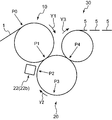
- FIG. 2 is a schematic side view showing a processing apparatus that performs the above-described steps (6) to (8).
- the processing apparatus receives the sheet 1 after the process (5) is performed at the receiving position P0 and performs the process (6), and the transport apparatus at the delivery position P1.
- a cutting device 20 that delivers the sheet 1 from 10 and performs the steps (7) and (8); a delivery device 30 that delivers the disposable diaper 5 from the cutting device 20 at the delivery position P4 and delivers it to the downstream step; It has.
- the cutting device 20 accepts (holds and holds) the sheet 1 from the conveying device 10 and cuts the sheet 1 at a predetermined cutting pitch.
- the cutting device 20 includes a transport drum 21 for transporting the sheet 1 and a cutting unit 22 for cutting the sheet 1 transported by the transport drum 21.
- the transport drum 21 includes a plurality of suction units 23 that suck and hold the sheet 1, a folding drive mechanism 24 that drives the suction units 23 to perform the step (8), and the suction unit 23 and the folding drive mechanism 24 in advance. And a holding mechanism (not shown) that holds the set rotation axis so as to be rotatable in the direction of the arrow Y2. The holding mechanism holds the suction units 23 so that the suction surfaces for sucking the sheets 1 in the plurality of suction units 23 are arranged on the same circumference and the plurality of suction units 23 can rotate.
- the suction unit 23 includes a main body suction portion 23a that sucks a portion of the sheet 1 to which the diaper main body 2 is bonded, and a pair of flap suction portions 23b that suck a portion corresponding to the flap portion of the sheet 1. Yes.
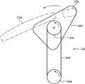
- the folding drive mechanism 24 drives the flap adsorbing portion 23b so that the flap adsorbing portion 23b overlaps the sheet 1 (diaper main body 2) adsorbed by the main body adsorbing portion 23a.
- the folding drive mechanism 24 includes a pair of pulleys 24 a and 24 c supported by a holding mechanism (not shown) and an endless belt spanned between the pulleys 24 a and 24 c.
- a belt 24b, a rotating arm 24d fixed to the pulley 24c, four pulleys 24e to 24h supported by the rotating arm 24d, and an endless belt 24i stretched over the pulleys 24e to 24h are provided. .
- a motor (not shown) is connected to the pulley 24a.
- the pulley 24a rotates in the direction indicated by the arrow in FIG. 4 by the driving force of the motor
- the pulley 24c rotates in the direction indicated by the arrow via the endless belt 24b.
- the rotating arm 24d fixed to the pulley 24c rotates in the direction indicated by the arrow in FIG. Since the flap adsorbing portion 23b is fixed to the distal end portion of the rotating arm 24d, the flap adsorbing portion 23b moves outside the main body adsorbing portion 23a according to the rotation of the pulley 24c (the rotation axis set in the holding mechanism). To the outside in the radial direction of the circle centered on.
- a motor (not shown) is also connected to a pulley 24f provided on the rotating arm 24d.
- the pulley 24f is rotated in the direction indicated by the arrow by the motor, the pulley is passed through the endless belt 24i. 24e rotates in the direction of the arrow.
- a flap adsorbing portion 23b is attached to the pulley 24e so as to be rotatable about the rotation axis of the pulley 24e. Therefore, according to the rotation of the pulley 24e, a portion corresponding to the flap portion of the sheet 1 sucked by the pulley 24e can be folded on the sheet 1 (diaper main body 2) sucked by the main body suction portion 23a.
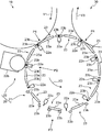
- the cutting unit 22 is set in advance as a position for cutting the plurality of anvils 22 a held by the holding mechanism of the transport drum 21 and the sheet 1 so as to be positioned between the suction units 23. And a rotary cutter 22b provided to face the anvil 22a at the cut position P2.
- the plurality of anvils 22a are arranged at equal intervals around the rotation axis of the transport drum 21, and rotate around the rotation axis. As a result, each anvil 22a sequentially faces the rotary cutter 22b as the transport drum 21 rotates, and the cutting pitch is defined by the facing interval.
- the sheet 1 is delivered from the conveying device 10 to the suction unit 23 at the delivery position P1, and the sheet 1 is cut when the conveying drum 21 rotates to the cutting position P2. Further, when the conveying drum 21 rotates to the folding position P3, the flap portion of the sheet 1 is folded so as to overlap the diaper main body 2, and the disposable diaper 5 is delivered from the cutting device 20 to the delivery device 30 at the delivery position P4.
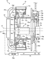
- the conveyance device 10 that conveys the sheet 1 so as to deliver the sheet 1 to the downstream cutting device 20 will be described with reference to FIGS. 6 and 7.
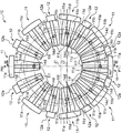
- the transport device 10 rotates the suction members 11 and 12 around a plurality of suction members 11 and 12 having suction surfaces (reference numerals omitted) that can suck the sheet 1 and a first axis J1 extending in the horizontal direction.
- a transport device main body 13 that supports the suction member 11, a drive device 14 that rotationally drives the suction members 11 and 12, and a suction mechanism 15 that applies suction force to the suction members 11 and 12 are provided.
- the adsorbing member 11 includes an adsorbing portion 11a having an adsorbing surface, a pair of attachment plates 11b and 11c extending from the adsorbing portion 11a toward the first axis J1 and facing in a direction parallel to the first axis J1, and a pair of attachments
- the sliders 11d and 11e are provided on the surfaces of the plates 11b and 11c facing each other, and the rail 11f is provided on the surface of the mounting plate 11b opposite to the slider 11d.
- the adsorption part 11a is a box-shaped member having a decompression chamber that is decompressed by being connected to a suction source 15a described later.
- the suction part 11a is formed with a communication hole for communicating the decompression chamber and the outside of the suction part 11a on the suction surface facing away from the first axis J1, and the suction surface sucks air on the suction surface through the communication hole.
- the suction surface is a surface formed along a circumference centered on the first axis J1.
- the suction member 12 has the same configuration as the suction member 11 except that the suction member 12 has a suction portion 12a having a suction surface instead of the suction portion 11a.
- the suction portion 12a has a width dimension narrower than that of the suction portion 11a in the circumferential direction around the first axis J1, and the suction surface of the suction portion 12a is also narrower than the suction surface of the suction portion 11a in the circumferential direction.
- the suction surface of the suction portion 11 a has a width dimension that can suck the diaper main body 2 and a part of the flap portion protruding from both sides in the width direction.
- the suction surface of the suction portion 12a has a width dimension capable of sucking a part of the flap portion protruding in the width direction from the suction surface of the suction portion 11a.
- the transport device body 13 includes a support member 16 installed on a preset installation surface of the transport device 10 and a direction perpendicular to the first axis J ⁇ b> 1 with respect to the support member 16.
- a holding mechanism 17 attached to the support member 16 so as to be movable, and a moving device 18 that provides power for moving the holding mechanism 17 with respect to the support member 16.
- the holding mechanism 17 includes a support plate 17a attached to a support member 16 to be described later via a pair of upper and lower sliders 17b and 17c, and a side opposite to the sliders 17b and 17c in a direction parallel to the first axis J1 from the support plate 17a.
- a cylindrical portion 17d that extends in the radial direction, a pair of flanges 17e, 17f that protrude from the outer peripheral surface of the cylindrical portion 17d in the radial direction of the circle centered on the first axis J1 and that are opposed to the direction parallel to the first axis J1; 17e and 17f, rails 17g and 17h provided respectively on the opposite surfaces of the surfaces facing each other.
- the flanges 17e and 17f and the rails 17g and 17h are provided over the entire circumference of a circle centered on the first axis J1.
- the pair of flanges 17e and 17f and the rails 17g and 17f are inserted between the mounting plates 11b and 11c of the suction members 11 and 12, and the sliders of the suction members 11 and 12 are slidable on the rails 17g and 17f. Is engaged. Accordingly, the suction members 11 and 12 are held by the cylindrical portion 17d in a state where the suction members 11 and 12 can move on a path along a circle centered on the first axis J1 defined by the rails 17g and 17f.
- the holding mechanism 17 is in a state in which the suction surface extends at intervals along the circumference centered on the first axis J1 and the plurality of suction members 11 and 12 are rotatable about the first axis J1.
- the suction members 11 and 12 are held.
- the holding mechanism 17 includes the eight adsorbing members 11 and the eight adsorbing members 12 so that the adsorbing members 11 and the adsorbing members 12 are alternately arranged along the circumference around the first axis J1. Hold.
- the drive device 14 includes a motor main body 14a fixed to the support member 16 via a bracket 16e, a rotary shaft 14b extending from the motor main body 14a to the opposite side of the support member 16, and a disk-like connection fixed to the rotary shaft 14b. It has a plate 14c, 16 connection pins 14d attached to the peripheral edge of the connection plate 14c, and a slider 14e engaged with the rails 11f of the suction members 11 and 12.
- the motor main body 14a has a portion that is supported by the support member 16 by the bracket 16e through the inside of the cylindrical portion 17d and that is accommodated in the cylindrical portion 17d, and is centered on a second axis J2 that is parallel to the first axis J1.
- the rotary shaft 14b is rotated.
- the cylindrical portion 17d extends in a direction parallel to the first axis J1 on one side of the support member 16 and the moving device 18 (support mechanism) in a direction parallel to the first axis J1, and includes a plurality of suction members 11, This corresponds to a cylindrical holding member main body having an outer peripheral surface for holding 12.
- the connecting plate 14c, the connecting pin 14d, and the slider 14e extend from the motor main body 14a to a position opposite to the support member 16 of the cylindrical portion 17d so that the power from the rotating shaft 14b can be transmitted to the attracting members 11 and 12.
- This corresponds to a connecting mechanism that connects the extending rotating shaft 14b and the plurality of suction members 11 and 12.
- the peripheral edge portion of the connecting plate 14c is parallel to the first axis J1 at a position opposite to the attaching plate 11c of the attaching plate 11b of the suction members 11 and 12. It faces the mounting plate 11b in any direction.
- the connecting pin 14d extends in a direction parallel to the first axis J1, and penetrates the connecting plate 14c so as to be rotatable with respect to the connecting plate 14c about the axis of the connecting pin 14d.
- the end of the connecting pin 14d on the side close to the mounting plate 11b is fixed to the slider 14e.
- the slider 14e is engaged with the rail 11f so as to be movable along the longitudinal direction of the rail 11f of the suction members 11 and 12.
- the rail 11 f extends along the radial direction of a circle centered on the first axis J ⁇ b> 1.
- the coupling mechanism (the coupling plate 14c, the coupling pin 14d, and the slider 14e) is configured such that the plurality of adsorption members 11 and 12 are movable in the radial direction of the circle having the first axis J1 as the center. 12 is connected.
- the suction mechanism 15 includes a suction source 15a, a suction duct 15b that is connected to the suction source 15a and connected to the mounting plate 11b of the suction members 11 and 12 via a bracket 15d, and the suction duct 15b and the suction member. 11 and 12 adsorbing portions 11a and 16a.
- the support member 16 is erected on a preset installation surface of the conveying device 10 and has a base plate 16a to which the driving device 14 (motor body 14a) is fixed via a bracket 16e, and a holding mechanism 17 side of the base plate 16a. And a pair of rails 16c and 16d fixed to the surface of the sub plate 16b on the holding mechanism 17 side.
- the bracket 16e extends from the motor body 14a to the base plate 16a through holes formed in the support plate 17a and the sub plate 16b.
- Each of the rails 16c and 16d extends along a direction orthogonal to the first axis J1.
- the sliders 17b and 17c of the holding mechanism 17 are engaged with these rails 16c and 16d in a slidable manner along the longitudinal direction of the rails 16c and 16d (direction perpendicular to the first axis J1). .
- a support wall 17i that supports the motor main body 14a and a rail 17j that is fixed to the support wall 17i are provided inside the cylindrical portion 17d of the holding mechanism 17.
- the rail 17j extends in a direction parallel to the rails 16c and 16d of the support member 16.
- a slider 14f fixed to the motor main body 14a is engaged with the rail 17j so as to be slidable along the longitudinal direction of the rail 17j.
- the support member 16 is held so that the holding mechanism 17 and the driving device 14 are relatively movable in the longitudinal direction of the rails 16c and 16d (rail 17j), that is, in the direction orthogonal to the first axis J1.
- the mechanism 17 and the driving device 14 are supported.
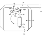
- FIG. 9 and 10 show a state when the support member 16 and the moving device 18 in FIG. 7 are viewed from the side opposite to the holding mechanism 17, and the base plate 16a is omitted.
- the moving device 18 is connected to the holding mechanism 17 and the support member 16, and holds the force for moving the holding mechanism 17 in a direction orthogonal to the first axis J ⁇ b> 1. 17 to give.
- the moving device 18 has an air cylinder having a cylinder body 18a and a rod 18c.
- the base end portion of the cylinder body 18a is fixed to the base plate 16a so as to be rotatable about an axis 18b parallel to the first axis J1.
- the tip of the rod 18c is attached to one end of the link 18e so as to be rotatable about an axis 18d parallel to the first axis J1.
- the other end of the link 18e is fixed to the base plate 16a so as to be rotatable about an axis 18f parallel to the first axis J1. Further, the intermediate portion of the link 18e is fixed to one end portion of the link 18h so as to be rotatable about an axis 18g parallel to the first axis J1. The other end of the link 18h is fixed to the support plate 17a of the holding mechanism 17 so as to be rotatable about an axis 18i parallel to the first axis J1.
- the support member 16 is arranged so that the first axis J1 and the second axis J2 are arranged at different positions when the rod 18c of the air cylinder is contracted.
- the holding mechanism 17 and the driving device 14 are supported. Since the first axis J1 and the second axis J2 are arranged at different positions in this way, the position of the connecting pin 14d with respect to the suction members 11 and 12, that is, the second shaft J2 that is the center of rotation, the suction surface. Since the radii (angular velocities) are different, the interval between the adjacent suction surfaces can be changed in the circumferential direction around the first axis J1.
- the receiving position P0 is set at one of two intersection points of a straight line passing through the first axis J1 and the second axis J2 and a circle centered on the first axis J1, and the two intersection points A delivery position P1 is set on the other side. That is, the position where the distance between adjacent suction surfaces is the largest is set as the receiving position P0, and the position where the distance between adjacent suction surfaces is the smallest is set as the delivery position P1. Therefore, the length of the sheet 1 sucked and held by the two suction surfaces adjacent to each other can be effectively reduced between the receiving position P0 and the delivery position P1. Thereby, the process (5) of FIG. 1 can be performed.
- the length of the sheet 1 received by the cutting device 20 at the delivery position P1 is the distance between the pair of flap suction portions 23b provided on both sides of the main body suction portion 23a in the suction unit 23, that is, These are fixed by the cutting pitch set in the cutting device 20 (see FIG. 3). Therefore, the length of the sheet 1 delivered from the conveying device 10 at the delivery position P1 needs to be matched with this. Therefore, in the suction members 11 and 12, the relative position between the holding mechanism 17 and the driving device 14 is in the first state (the state shown in FIG. 6) so that the distance between two adjacent suction surfaces at the delivery position P1 is small. In the case of being changed from the second state to the second state (the state shown in FIG. 11), spacers 11g and 12g used only in the second state are further provided.
- the suction members 11 and 12 are provided on the first axis J1 side of the suction portions 11a and 12a in the radial direction of the circle centering on the suction portions 11a and 12a and the first axis J1, and the holding mechanism 17 and Connecting portions (mounting plates 11b, 11c) connected to the connecting mechanism (connecting plate 14c, connecting pin 14d, and slider 14e), spacers 11g, 12g interposed between the adsorbing portions 11a, 12a and the connecting portion, Have
- Each of the spacers 11g and 12g has a first state in which the length of the sheet 1 adsorbed between two adsorbing surfaces adjacent to each other at the delivery position P1 set on the circumference centered on the first axis J1 (FIG. No. 6 state) and the second state (state of FIG. 11) have the thickness dimension set to be the same. Further, the spacers 11g and 12g can be attached to and detached from the suction portions 11a and 12a and the connection portion.
- the relative position of the holding mechanism 17 and the driving device 14 is set to the second state (the state shown in FIG. 11)
- the rate of change in the length is determined by the relative position between the first axis J1 and the second axis J2, and is constant regardless of the radius from the first axis J1 to the suction surface. Therefore, by attaching the spacers 11g and 12g having the same thickness dimension set as described above to all the suction members 11 and 12, the circumference around the first axis J1 formed by the suction surface is long. However, it is possible to maintain the change ratio of the length of the sheet 1 that changes between the receiving position P0 and the delivery position P1. Since the length of the sheet 1 at the delivery position P1 can be maintained in the first state and the second state, the delivery position P1 can be maintained.
- the length of the sheet 1 at the delivery position P1 is adjusted by adjusting at least one of the delivery position P0 and the delivery position P1 without using the spacers 11g and 12g in the second state. It can also be adjusted to what is required by the cutting device 20.
- FIG. 12 shows an example in which the receiving position P0 and the delivery position P1 are changed.
- a delivery position P1 is set at one of two intersections of a straight line passing through the first axis J1 and the second axis J2 and a circle centered on the first axis J1, and of the two intersections
- the receiving position P0 is set (setting step).
- the support member 16 to which one of the drive devices 14 is fixed, the holding mechanism 17 and the support member 16 are connected to move the holding mechanism 17 in a direction perpendicular to the first axis J1 with respect to the support member 16.
- a support mechanism including a moving device 18 that applies force to the holding mechanism 17 is prepared (support mechanism preparation step).
- the rotating shaft 14b is driven to rotate about the second axis J2 by the motor body 14a (first conveying step). Accordingly, the plurality of suction members 11 and 12 are rotated around the first axis J1 to convey the sheet 1 while sucking the sheets to the suction surfaces of the plurality of suction members 11 and 12.
- the sheet 1 conveyed in the first conveying step is cut using the cutting device 20 (first cutting step).
- the length of the sheet 1 delivered to the cutting device 20 is required to be changed.
- the holding mechanism 17 and the driving device 14 are relatively moved in the direction orthogonal to the first axis J1 by the support mechanism (the support member 16 and the moving device 18), thereby connecting the connection mechanism (the connection plate 14c, the connection pin 14d, The slider 14e) is moved in the radial direction of the circle centered on the first axis J1 (moving step).
- the relative position between the holding mechanism 17 and the driving device 14 is changed from the first state (FIG. 6) to the second so that the distance between two adjacent suction surfaces at the delivery position P1 is reduced. Change to the state (FIG. 11).
- the suction portions 11a and 12a having the suction surface and the suction portion 11a in the radial direction of the circle centered on the first axis J1.
- a plurality of adsorbing members 11 and 12 each having spacers 11g and 12g that are detachable between 12a and the connecting portion are prepared in advance (adsorbing member preparing step).
- the length of the sheet 1 sucked and held between two adjacent suction surfaces at the delivery position P1 is set to be the same in the first state and the second state.
- Spacers 11g and 12g having thickness dimensions are prepared.
- the spacers 11g and 12g are attached between the suction portions 11a and 12a and the connection portion during the execution period of the stop step (attachment step).
- spacers 11g and 12g are attached between the suction portions 11a and 12a and the mounting plates 11b and 11c as necessary.
- the sheet 1 conveyed in the second conveying step is cut using the cutting device 20 (second cutting step).
- the sheet 1 is cut at the same cutting pitch.
- the relative positional relationship between the sheet conveying device 10 and the cutting device 20 in the circumferential direction around the first axis J1 is the same.
- the support mechanism is configured to move the plurality of suction members 11 and 12 in the radial direction of the circle having the first axis J1 as the center with respect to the connection member (the connection plate 14c, the connection pin 14d, and the slider 14e).
- the holding mechanism 17 and the driving device 14 can be relatively moved in the direction orthogonal to the first axis J1 by the (supporting member 16 and the moving device 18).
- the position of the rotation axis (second axis J2) of the drive device 14 is changed with respect to the first axis J1 in a state where the position of the suction surface is constrained on the circumference of a circle centered on the first axis J1. can do.
- the distance from the second axis J2 that is the center of rotation to each suction surface, that is, the angular velocity of each suction surface during rotation is changed, and the interval between adjacent suction surfaces is a circle centered on the first axis J1. It changes on the circumference.
- the length of the sheet sucked and held by the two suction surfaces adjacent to each other can be changed on the circumference of the circle having the first axis J1 as the center.
- the positional relationship between the first axis J1 and the second axis J2 is adjusted. By doing so, it is possible to easily change the length of the sheet 1 sucked and held on the two suction surfaces adjacent to each other between the receiving position P0 and the delivery position P1.
- the sheet 1 at the delivery position P ⁇ b> 1 changed by the conveying device 10 is used to cut the sheet at the same cutting pitch in the first cutting step and the second cutting step.
- the length of the finished product can be changed by the length of.
- the distance between the adsorbing surfaces adjacent on the circumference around the first axis J1 can be continuously changed. Therefore, even if the cutting pitch is fixed in the downstream cutting device 20, the length of the sheet 1 positioned within the cutting pitch by changing the receiving position P0 and the delivery position P1 on the circumference in the conveying device 10 Then, the sheet 1 can be transferred to the cutting device 20. However, in this case, it takes time to change the receiving position P0 and the delivery position P1 in the conveying device 10 in order to change the length of the sheet 1 positioned within the cutting pitch.
- the rate of change in the length of the sheet 1 between the receiving position P0 and the delivery position P1 of the sheet 1 in the conveying device 10 is determined by the relative position between the first axis J1 and the second axis J2. It is constant regardless of the radius from the first axis J1 to the suction surface. Therefore, as in the above-described embodiment, if each of the spacers 11g and 12g has the same thickness dimension set as described above, the rate of change in the length of the sheet 1 is maintained while the delivery position P1 is maintained. The length of the sheet can be maintained. In other words, the delivery position P1 can be made constant even after the length of the sheet 1 is changed.
- the receiving position P0 or the delivery position P1 is set at the position farthest from the first axis J1 (one of the two intersections) and the position closest to the first axis J1. Therefore, the ratio of the change in the length of the sheet 1 between the receiving position P0 and the delivery position P1 can be set to the maximum.
- the holding mechanism 17 and the driving device 14 can be relatively moved by the moving device 18, workability is improved as compared with the case where they are moved manually.
- the motor main body 14a and the cylindrical portion (holding member main body) 17d are overlapped in the direction parallel to the first axis J1. Therefore, it is possible to reduce the size of the transport device 10 in the same direction.
- the length of the sheet 1 received by the cutting device 20 from the conveying device 10 is kept constant, and the length of the sheet 1 is adjusted by the conveying device 10 by fixing the cutting pitch of the cutting device 20.
- the length of the sheet 1 after cutting can be changed by the amount of breakage.
- the spacer 11g is used as described above, or the delivery position as shown in FIG. Adjustment of P1 is necessary. Therefore, the work for changing the cutting length of the sheet 1 becomes complicated.
- FIGS. 13 to 17 show a processing apparatus according to another embodiment for performing the steps (6) to (7) shown in FIG. 1 described above.
- This processing apparatus accepts the sheet 1 after the process (5) is performed at the receiving position P0 and performs the process (6), and transfers the sheet 1 from the transport apparatus 10 at the delivery position P1.
- the cutting device 40 which performs a process (7) and the delivery apparatus 30 which delivers the disposable diaper 5 from the cutting device 40 in the delivery position P4 to a downstream process are provided.
- the conveyance apparatus 10 and the delivery apparatus 30 have the structure similar to the thing in embodiment mentioned above, the description is abbreviate
- the cutting device 40 includes a cutting rotator 41 having an outer peripheral surface 41 a that sucks the sheet 1 at the delivery position P ⁇ b> 1, and an outer peripheral surface of the cutting rotator 41 with a preset time interval.
- the cutting rotator 41 is rotatable around a third axis J3 that is parallel to the first axis J1 of the transport device 10.
- the cutting mechanism 42 includes a cutting drum 42a provided to face the outer peripheral surface 41a of the cutting rotary body 41 at the cutting position P2, and a cutting drive source 42b that rotationally drives the cutting drum 42a.
- the cutting drum 42a has a drum main body and a cutting blade intermittently provided in the circumferential direction with respect to the outer peripheral surface of the drum main body, and the cutting blade contacts the outer peripheral surface of the cutting rotating body 41 at predetermined time intervals.
- the sheet 1 is cut by sandwiching the sheet 1 therebetween.
- the cutting drive source 42b is constituted by a motor having a rotating shaft connected to the cutting drum 42a so as to be rotatable about a fourth axis J4 parallel to the first axis J1.
- the rotating body drive source 43 is configured by a servo motor having a rotating shaft connected to the cutting rotating body 41 so as to be rotatable about the third axis J3.
- the controller 44 controls the rotating body drive source 43 to adjust the speed of the cutting rotating body 41 and controls the cutting drive source 42b to adjust the speed of the cutting drum 42a.
- FIG. 17 shows the control content of the rotating body drive source 43 executed by the controller 44.
- the controller 44 determines the length of the sheet 1 that passes through the delivery position P ⁇ b> 1 within a time interval in which the cutting blade of the cutting mechanism 42 sandwiches the sheet 1 with the outer peripheral surface of the cutting rotating body 41.
- the rotating body drive source 43 is controlled so that the lengths of the sheets 1 passing through the cutting position P2 within the time interval become different lengths.
- a plurality of cutting target positions 1a1 to 1a3 set in advance as positions to be cut by the cutting mechanism 42 are set.
- the controller 44 determines that the first cutting target position 1a1 is cut after the first cutting target position 1a1 of the cutting target positions 1a1 to 1a3 reaches the delivery position P1 (see FIG. 13).
- the speed of the cutting rotator 41 is changed until the position P2 is reached (see FIG. 14).
- the controller 44 changes the speed of the cutting rotary body 41 until the portion (cutting portion) corresponding to the first cutting target position 1a1 reaches the delivery position P4 from the cutting position P2 (see FIG. 15).
- the controller 44 changes the speed of the cutting rotator 41 between the time when the second cutting target position 1a2 reaches the delivery position P1 and the time when it reaches the cutting position P2 (see FIG. 16). Thereafter, the controller 44 executes similar control for the third cutting target position 1a3 subsequent to the second cutting target position 1a2.
- the controller 44 includes a control map C1 for a normal size, a control map C2 for a size smaller than the normal size, and a control for a size larger than the normal size.
- a map C3 is stored.
- the controller 44 accelerates the cutting rotary body 41 until the cutting target positions 1a1 to 1a3 move from the delivery position P1 to the cutting position P2, and the cutting target positions 1a1 to 1a3. Before moving from the cutting position P2 to the delivery position P4, the cutting rotary body 41 is decelerated and returned to the speed before acceleration.
- the length of the sheet 1 that passes through the delivery position P1 within the time interval of the cutting mechanism 42 can be made longer than the length of the sheet 1 that passes through the cutting position P2 within the time interval.
- the speed of the sheet 1 received from the conveying device 10 at the delivery position P1 is set to be higher than that during the control execution by the control map C1.
- the controller 44 controls the cutting rotator 41 so as to match this speed, and decelerates the cutting rotator 41 until the cutting target positions 1a1 to 1a3 move from the delivery position P1 to the cutting position P2. To do.
- the speed of the decelerated seat 1 is lower than the lowest speed in the control map C1.
- the controller 44 accelerates the cutting rotating body 41 to return to the speed before deceleration until the cutting target positions 1a1 to 1a3 move from the cutting position P2 to the delivery position P4.
- the length of the sheet 1 that passes through the delivery position P1 within the time interval of the cutting mechanism 42 can be made shorter than the length of the sheet 1 that passes through the cutting position P2 within the time interval.
- the speed of the sheet 1 received from the conveying device 10 at the delivery position P1 is set to be lower than that during control execution by the control map C1.
- the controller 44 controls the cutting rotator 41 so as to match this speed, and accelerates the cutting rotator 41 until the cutting target positions 1a1 to 1a3 move from the delivery position P1 to the cutting position P2. To do.
- the speed of the accelerated sheet 1 is the same as the highest speed in the control map C1.
- the controller 44 decelerates and returns the cutting rotating body 41 to the speed before acceleration until the cutting target positions 1a1 to 1a3 move from the cutting position P2 to the delivery position P4.
- the length of the sheet 1 that passes through the delivery position P1 within the time interval of the cutting mechanism 42 can be made shorter than the length of the sheet 1 that passes through the cutting position P2 within the time interval.
- controller 44 controls the speed of the cutting drum 42a so as to coincide with the speed of the sheet 1 at the cutting position P2 controlled as described above.
- the cutting device 40 is prepared (cutting device preparation step).
- first transport step, the first cutting step, the stop step, the moving step, the second transport step, and the second cutting step in the above-described embodiment are executed.
- the length of the sheet 1 that passes through the delivery position P1 within the time interval is different from the length of the sheet 1 that passes through the cutting position P2 within the time interval.
- the speed of the cutting rotating body 41 is adjusted.
- the length of the sheet 1 that passes through the delivery position P1 within the time interval and the length of the sheet 1 that passes through the cutting position P2 within the time interval are set to different lengths. Can be set. Therefore, whatever the length of the sheet 1 received by the cutting rotator 41 from the conveying device 10 at the delivery position P1, the rotation speed of the cutting rotator 41 is controlled to obtain a desired value.
- the sheet 1 can be cut at a pitch. Therefore, the cutting length of the sheet 1 can be easily changed.
- the rotation section A1 where the speed is constant in FIG. 17 corresponds to a section in which the diaper main body 2 (absorbent core when there is an absorbent core) passes the delivery position P1 and the delivery position P4.
- the delivery speed from the conveying device 10 to the cutting rotator 41 is maintained by keeping the rotation speed of the cutting rotator 41 constant, and the cutting is performed.
- the delivery from the rotary body 41 to the delivery device 30 can be performed smoothly.
- the spacers 11g and 12g are used, but at least one of the receiving position P0 and the delivery position P1 can be changed without using the spacers 11g and 12g.
- the receiving position P0 and the delivery position P1 are set at two intersections between a straight line passing through the first axis J1 and the second axis J2 and a circle centered on the first axis J1. You may arrange
- the transport device 10 used for manufacturing the disposable diaper 5 is illustrated, but the purpose of using the transport device 10 is not limited to the disposable diaper 5.
- the present invention provides a sheet conveying apparatus that continuously conveys the sheet so as to deliver the sheet to a downstream apparatus, each having a plurality of adsorption surfaces that can adsorb the sheet.
- the adsorbing member and the adsorbing surface are arranged at intervals along the circumference of a circle centered on the first axis, and the plurality of adsorbing members are rotatable about the first axis.
- a holding mechanism that holds a plurality of suction members, a rotation shaft that can rotate about a second axis parallel to the first axis, and power from the rotation shaft can be transmitted to the plurality of suction members.
- a drive mechanism having a connection mechanism for connecting the rotating shaft and the plurality of suction members; and a support mechanism for supporting the holding mechanism and the drive device, wherein the connection mechanism includes the plurality of suction members.
- the connection mechanism includes the plurality of suction members.
- the support mechanism is connected to the plurality of suction members while being movable in a radial direction, and the support mechanism is configured so that the holding mechanism and the driving device are relatively movable in a direction perpendicular to the first axis.
- a sheet conveying device that supports a holding mechanism and the driving device.
- the holding mechanism and the driving device are relatively moved in the direction orthogonal to the first axis by the support mechanism while moving the plurality of suction members with respect to the coupling member in the radial direction of the circle having the first axis as the center. Can be moved.
- the position of the rotating shaft (second axis) of the drive device can be changed with respect to the first axis in a state where the position of the suction surface is constrained on the circumference of a circle centered on the first axis. .
- the distance from the second axis, which is the center of rotation, to each suction surface, that is, the angular velocity of each suction surface during rotation is changed, and the interval between adjacent suction surfaces is a circle around the first axis. Vary on.
- the length of the sheet that is sucked and held by the two suction surfaces adjacent to each other can be changed on the circumference of a circle centered on the first axis.
- the processing pitch for example, the conventional cutting pitch
- the processing is performed by changing the receiving position and the delivery position on the circumference in the conveying device.
- the sheet can be transferred to the downstream apparatus.
- the plurality of suction members are provided on the first axis side of the suction portion in a radial direction of a suction portion having the suction surface and a circle centered on the first axis.
- the spacer delivers the sheet to the downstream device. Therefore, the relative position between the holding mechanism and the driving device is set so that the distance between two adjacent suction surfaces at the delivery position set in advance on the circumference around the first axis is small.
- each of the spacers in the plurality of suction members includes two adjacent suctions at the delivery position. It is preferred to have a set thickness to be the same in the state length said first state and said second sheet to be adsorbed between the surfaces.
- the ratio of the change in the length of the sheet between the sheet receiving position and the delivery position in the sheet conveying apparatus is determined by the relative position between the first axis and the second axis, and is from the first axis to the suction surface. Constant regardless of radius. Therefore, if each spacer has the same thickness dimension set as described above, the length of the sheet at the delivery position can be maintained while maintaining the rate of change in the length of the sheet. In other words, the delivery position can be kept constant even after the sheet length is changed.
- the delivery position is set to one of two intersections of a straight line passing through the first axis and the second axis and a circle centered on the first axis, It is preferable that the receiving position set in advance on the circumference around the first axis for receiving is set at the other of the two intersections.
- the receiving position or the delivery position is set at a position farthest from the first axis (one of the two intersections) and a position closest to the first axis. Therefore, the ratio of the change in the sheet length between the receiving position and the delivery position can be set to the maximum.
- the support mechanism includes a support member to which one of the holding mechanism and the driving device is fixed, and the other of the holding mechanism and the driving device and the support member to be connected to the holding mechanism and the driving device. It is preferable that the apparatus includes a moving device that applies a force to the other of the holding mechanism and the driving device to move the other of the devices in a direction perpendicular to the first axis with respect to the support member.
- the holding mechanism and the driving device can be relatively moved by the moving device, workability is improved as compared with the case where these are moved manually.
- the holding mechanism extends in a direction parallel to the first axis on one side of the support mechanism in a direction parallel to the first axis.
- a cylindrical holding member main body having an outer peripheral surface for holding the plurality of suction members is provided, and the driving device is supported by the support mechanism through the inside of the holding member main body and accommodated in the holding member main body.
- a motor main body that rotates the rotary shaft, and the connecting mechanism extends from the motor main body to a position opposite to the support mechanism of the holding member main body and the plurality of rotary shafts. It is preferable to connect the adsorption member.
- the motor main body and the holding member main body can be arranged in a direction parallel to the first axis, the transport device in the same direction can be reduced in size.
- the present invention is also a sheet processing apparatus that cuts a sheet at a predetermined length, the sheet conveying apparatus, and a cutting apparatus that takes the sheet from the sheet conveying apparatus and cuts the sheet at a predetermined pitch.
- a sheet processing apparatus is provided.
- the present invention even if it is necessary to change the length of the sheet positioned between the pitches set in the cutting device, it is easy to change the relative position between the holding mechanism and the driving device in the transport device.
- the sheet length between pitches can be changed.
- the length of the sheet taken by the cutting device from the conveying device is kept constant, and the cutting length of the sheet is adjusted by the conveying device by fixing the cutting pitch of the cutting device. Can be changed.
- the length of the sheet at the delivery position in the transport device to the sheet length set in the cutting device, it is necessary to use a spacer as described above or adjust the delivery position. Therefore, the work for changing the cutting length of the sheet becomes complicated.
- the cutting device sucks the sheet at a delivery position set in advance on a circumference around the first axis so that the conveying device delivers the sheet to the processing apparatus.
- a cutting rotator having an outer peripheral surface that is rotatable about a third axis parallel to the first axis, and an outer peripheral surface of the cutting rotator having a predetermined time interval at a preset cutting position
- a controller that controls the drive source so that the length of the sheet passing through the cutting position within the interval is different.
- the length of the sheet passing through the delivery position within the time interval and the length of the sheet passing through the cutting position within the time interval can be set to different lengths. Therefore, regardless of the length of the sheet received by the cutting rotator from the conveying device at the delivery position, the sheet is cut at a desired pitch by controlling the rotation speed of the cutting rotator. can do. Therefore, the cutting length of the sheet can be easily changed.
- the present invention is a sheet conveying method using the sheet conveying apparatus, wherein the plurality of suction members are centered on the first axis by rotating the rotational axis about the second axis.
- a second conveying step of conveying the sheet by rotationally driving the rotating shaft again about the second axis.
- the rotating shaft is temporarily stopped, and the holding mechanism and the driving device are relatively moved to thereby attract the coupling mechanism and the suction mechanism.
- the connection position with the member is moved in the radial direction of a circle around the first axis.
- the holding portion and the coupling mechanism are provided on the first axis side of the suction portion in the radial direction of a circle centered on the first axis and the suction portion having the suction surface.
- the relative position between the holding mechanism and the driving device is changed from the first state to the second state so that the distance between two adjacent suction surfaces at the delivery position set in advance on the circumference becomes small. Furthermore, in the suction member preparation step, the length of the sheet sucked between two adjacent suction surfaces at the delivery position is set to be the same in the first state and the second state. It is preferable to prepare the spacer having a different thickness dimension.
- the ratio of the change in the length of the sheet between the receiving position and the delivery position of the sheet can be determined.
- the length of the sheet at the delivery position can be maintained while maintaining. In other words, the delivery position can be kept constant even after the sheet length is changed.
- the delivery position is set at one of two intersections of a straight line passing through the first axis and the second axis and a circle centered on the first axis. It is preferable that a setting step of setting a receiving position set in advance on a circumference around the first axis to receive the sheet is further provided at the other of the two intersections.
- the receiving position or the delivery position can be set at a position farthest from the first axis (one of the two intersections) and a position closest to the first axis. Therefore, the ratio of the change in the sheet length between the receiving position and the delivery position can be set to the maximum.
- the sheet conveying method includes a supporting member to which one of the holding mechanism and the driving device is fixed, the other of the holding mechanism and the driving device, and the other of the holding mechanism and the driving device connected to the supporting member.
- a support mechanism preparing step of preparing the support mechanism comprising: a moving device that applies to the other of the holding mechanism and the drive device a force for moving the support member in a direction orthogonal to the first axis.
- the connecting position of the coupling mechanism and the plurality of suction members is moved in a radial direction of a circle centered on the first axis using the moving device.
- the present invention is a sheet processing method for processing the sheet using the sheet conveying apparatus and a cutting apparatus that takes the sheet from the sheet conveying apparatus and cuts the sheet at a predetermined pitch.
- the rotation shaft is driven to rotate about the second axis to rotate the plurality of suction members about the first axis so that the sheets are sucked to the suction surfaces of the plurality of suction members.
- the connection mechanism and the plurality of suction members are connected by relatively moving the holding mechanism and the driving device in a direction orthogonal to the first axis.
- a moving step for moving the apparatus in a radial direction of a circle centered on the first axis a second conveying step for conveying the sheet by rotationally driving the rotating shaft again about the second axis, And a second cutting step of cutting the sheet transported in two transport steps using the cutting device.
- the length of the sheet that is sucked and held by the two suction surfaces adjacent to each other can be changed on the circumference of a circle centered on the first axis.
- the length of the sheet taken by the cutting device from the sheet conveying device can be easily changed.
- the sheet processing method it is preferable that the sheet is cut at the same pitch in the first cutting step and the second cutting step.
- the sheet is cut at the same pitch in the first cutting step and the second cutting step, so that only the length of the sheet changed by the sheet conveying device is obtained.
- the length of the finished product can be changed.
- the suction portion having the suction surface and the holding mechanism and the coupling mechanism provided on the first axis side of the suction portion in a radial direction of a circle centered on the first axis.
- the relative position between the holding mechanism and the driving device is changed from the first state to the second state so that the distance between two adjacent suction surfaces at the delivery position set in advance on the circumference becomes small. Furthermore, in the suction member preparation step, the length of the sheet sucked between two adjacent suction surfaces at the delivery position is set to be the same in the first state and the second state.
- the spacers having different thickness dimensions are prepared, and in the first cutting step and the second cutting step, the relative positions of the sheet conveying device and the cutting device in the circumferential direction around the first axis The relationship is preferably the same.
- the spacer having the same thickness dimension set in this way between the suction portion and the connection portion in the attachment step By mounting the spacer having the same thickness dimension set in this way between the suction portion and the connection portion in the attachment step, the change in the length of the sheet from the receiving position to the delivery position in the sheet conveying apparatus can be prevented.
- the length of the sheet at the delivery position can be adjusted while maintaining the ratio. Therefore, in the first cutting step and the second cutting step, the relative positional relationship between the sheet conveying device and the cutting device in the circumferential direction around the first axis can be made the same.
- the sheet length is adjusted by the conveying device by keeping the length of the sheet taken by the cutting device from the conveying device constant and fixing the cutting pitch in the first cutting step and the second cutting step.
- the length of the sheet after cutting can be changed by that amount.
- the sheet processing method includes an outer peripheral surface that sucks the sheet at a delivery position set in advance on a circumference around the first axis so that the transport device delivers the sheet to the processing device. And a cutting rotator rotatable around a third axis parallel to the first axis and an outer peripheral surface of the cutting rotator with a predetermined time interval at a preset cutting position. And a cutting device preparatory step for preparing the cutting device comprising a cutting mechanism for cutting the sheet by sandwiching the sheet at the second cutting step, wherein the second cutting step passes the delivery position within the time interval. It is preferable to adjust the speed of the cutting rotary body so that the length of the sheet to be performed and the length of the sheet passing through the cutting position within the time interval are different.
- the length of the sheet that passes to the delivery position within the predetermined time and the length of the sheet that passes to the cutting position within the time interval can be set to different lengths. Therefore, regardless of the length of the sheet received by the cutting rotator from the conveying device at the delivery position, the sheet is cut at a desired pitch by adjusting the rotation speed of the cutting rotator. can do. Therefore, the cutting length of the sheet can be easily changed.
Landscapes
- Health & Medical Sciences (AREA)
- Engineering & Computer Science (AREA)
- Animal Behavior & Ethology (AREA)
- General Health & Medical Sciences (AREA)
- Biomedical Technology (AREA)
- Heart & Thoracic Surgery (AREA)
- Vascular Medicine (AREA)
- Life Sciences & Earth Sciences (AREA)
- Manufacturing & Machinery (AREA)
- Epidemiology (AREA)
- Public Health (AREA)
- Veterinary Medicine (AREA)
- Mechanical Engineering (AREA)
- Absorbent Articles And Supports Therefor (AREA)
- Feeding Of Articles By Means Other Than Belts Or Rollers (AREA)
- Manipulator (AREA)
Abstract
Priority Applications (6)
| Application Number | Priority Date | Filing Date | Title |
|---|---|---|---|
| US16/613,228 US11345556B2 (en) | 2017-05-16 | 2018-05-11 | Sheet conveying device and sheet processing device provided with same, and method for conveying sheet and method for processing sheet using sheet conveying device |
| BR112019024136-1A BR112019024136B1 (pt) | 2017-05-16 | 2018-05-11 | Dispositivo de transporte de chapa e dispositivo de processamento de chapa, método para transportar uma chapa usando o dispositivo de transporte de chapa, e método para processar uma chapa usando o dispositivo de transporte de chapa |
| MX2019013674A MX2019013674A (es) | 2017-05-16 | 2018-05-11 | Dispositivo de desplazamiento de laminas y dispositivo de procesamiento de laminas proporcionado con el mismo, metodo para transportar laminas y metodo para procesar laminas utilizando dispositivos de transporte. |
| EP18802295.8A EP3613392B1 (fr) | 2017-05-16 | 2018-05-11 | Dispositif d'acheminement de feuille et dispositif de traitement de feuille équipé dudit dispositif d'acheminement, et procédé d'acheminement de feuille et procédé de traitement de feuille à l'aide d'un dispositif d'acheminement de feuille |
| JP2019518749A JP7080227B2 (ja) | 2017-05-16 | 2018-05-11 | シート搬送装置及びこれを備えたシート加工装置並びにシート搬送装置を用いたシートの搬送方法及びシートの加工方法 |
| CN201880032122.5A CN110730646B (zh) | 2017-05-16 | 2018-05-11 | 片材搬运装置、片材加工装置、以及片材搬运方法及片材加工方法 |
Applications Claiming Priority (2)
| Application Number | Priority Date | Filing Date | Title |
|---|---|---|---|
| JP2017097344 | 2017-05-16 | ||
| JP2017-097344 | 2017-05-16 |
Publications (1)
| Publication Number | Publication Date |
|---|---|
| WO2018212092A1 true WO2018212092A1 (fr) | 2018-11-22 |
Family
ID=64273783
Family Applications (1)
| Application Number | Title | Priority Date | Filing Date |
|---|---|---|---|
| PCT/JP2018/018336 Ceased WO2018212092A1 (fr) | 2017-05-16 | 2018-05-11 | Dispositif d'acheminement de feuille et dispositif de traitement de feuille équipé dudit dispositif d'acheminement, et procédé d'acheminement de feuille et procédé de traitement de feuille à l'aide d'un dispositif d'acheminement de feuille |
Country Status (6)
| Country | Link |
|---|---|
| US (1) | US11345556B2 (fr) |
| EP (1) | EP3613392B1 (fr) |
| JP (1) | JP7080227B2 (fr) |
| CN (1) | CN110730646B (fr) |
| MX (1) | MX2019013674A (fr) |
| WO (1) | WO2018212092A1 (fr) |
Cited By (1)
| Publication number | Priority date | Publication date | Assignee | Title |
|---|---|---|---|---|
| WO2025115803A1 (fr) * | 2023-11-30 | 2025-06-05 | 株式会社瑞光 | Dispositif de fabrication et procédé de fabrication d'article absorbant |
Families Citing this family (3)
| Publication number | Priority date | Publication date | Assignee | Title |
|---|---|---|---|---|
| US12447727B2 (en) * | 2020-01-27 | 2025-10-21 | Panasonic Holdings Corporation | Laminating device, and manufacturing device for laminated electrode assembly |
| JP7110467B1 (ja) * | 2021-07-30 | 2022-08-01 | 株式会社瑞光 | 搬送装置 |
| CN119820652B (zh) * | 2025-01-23 | 2025-12-02 | 黄山富田精工智造股份有限公司 | 一种调距系统 |
Citations (5)
| Publication number | Priority date | Publication date | Assignee | Title |
|---|---|---|---|---|
| JPS564743B2 (fr) | 1976-07-09 | 1981-01-31 | ||
| JPS648184A (en) * | 1987-06-29 | 1989-01-12 | Uni Charm Corp | Applying of elastic band onto shifting web and device therefor |
| JPH11513647A (ja) * | 1995-10-17 | 1999-11-24 | キンバリー クラーク ワールドワイド インコーポレイテッド | 個々の部品を移動ウェブに付与するための装置と方法 |
| JP2002521091A (ja) * | 1998-07-22 | 2002-07-16 | ザ、プロクター、エンド、ギャンブル、カンパニー | 連続ウェブを輸送及び処理するための装置 |
| US20080196564A1 (en) * | 2007-02-21 | 2008-08-21 | Curt G. Joa, Inc. | Single transfer insert placement method and apparatus |
Family Cites Families (7)
| Publication number | Priority date | Publication date | Assignee | Title |
|---|---|---|---|---|
| US4726876A (en) * | 1985-10-18 | 1988-02-23 | Kimberly-Clark Corporation | Apparatus for repositioning discrete articles |
| JP2609252B2 (ja) * | 1987-08-18 | 1997-05-14 | ユニ・チャーム 株式会社 | 移動ウエブへの弾性バンド貼着装置 |
| US6620276B1 (en) | 1998-07-22 | 2003-09-16 | The Procter & Gamble Company | Apparatus for transporting a continuous web, and for manipulating the web |
| JP3798298B2 (ja) | 2000-12-01 | 2006-07-19 | 株式会社瑞光 | 回転装置、着用物品の搬送方法およびウェブの搬送方法 |
| DE112010001641T5 (de) | 2009-04-17 | 2012-08-02 | Zuiko Corporation | Klappenfaltsystem für wegwerfbaren, tragbaren Artikel |
| US10117788B2 (en) | 2012-07-06 | 2018-11-06 | Zuiko Corporation | Transport method, manufacturing method for disposable wearable article, as well as wearable article, and transport device |
| US9511951B1 (en) * | 2015-06-23 | 2016-12-06 | The Procter & Gamble Company | Methods for transferring discrete articles |
-
2018
- 2018-05-11 WO PCT/JP2018/018336 patent/WO2018212092A1/fr not_active Ceased
- 2018-05-11 CN CN201880032122.5A patent/CN110730646B/zh active Active
- 2018-05-11 EP EP18802295.8A patent/EP3613392B1/fr active Active
- 2018-05-11 MX MX2019013674A patent/MX2019013674A/es unknown
- 2018-05-11 US US16/613,228 patent/US11345556B2/en active Active
- 2018-05-11 JP JP2019518749A patent/JP7080227B2/ja active Active
Patent Citations (5)
| Publication number | Priority date | Publication date | Assignee | Title |
|---|---|---|---|---|
| JPS564743B2 (fr) | 1976-07-09 | 1981-01-31 | ||
| JPS648184A (en) * | 1987-06-29 | 1989-01-12 | Uni Charm Corp | Applying of elastic band onto shifting web and device therefor |
| JPH11513647A (ja) * | 1995-10-17 | 1999-11-24 | キンバリー クラーク ワールドワイド インコーポレイテッド | 個々の部品を移動ウェブに付与するための装置と方法 |
| JP2002521091A (ja) * | 1998-07-22 | 2002-07-16 | ザ、プロクター、エンド、ギャンブル、カンパニー | 連続ウェブを輸送及び処理するための装置 |
| US20080196564A1 (en) * | 2007-02-21 | 2008-08-21 | Curt G. Joa, Inc. | Single transfer insert placement method and apparatus |
Non-Patent Citations (1)
| Title |
|---|
| See also references of EP3613392A4 |
Cited By (1)
| Publication number | Priority date | Publication date | Assignee | Title |
|---|---|---|---|---|
| WO2025115803A1 (fr) * | 2023-11-30 | 2025-06-05 | 株式会社瑞光 | Dispositif de fabrication et procédé de fabrication d'article absorbant |
Also Published As
| Publication number | Publication date |
|---|---|
| BR112019024136A2 (pt) | 2020-06-02 |
| EP3613392A4 (fr) | 2020-11-18 |
| JPWO2018212092A1 (ja) | 2020-03-19 |
| EP3613392C0 (fr) | 2026-02-25 |
| EP3613392B1 (fr) | 2026-02-25 |
| US11345556B2 (en) | 2022-05-31 |
| CN110730646A (zh) | 2020-01-24 |
| EP3613392A1 (fr) | 2020-02-26 |
| MX2019013674A (es) | 2020-07-20 |
| US20200172361A1 (en) | 2020-06-04 |
| CN110730646B (zh) | 2021-10-22 |
| JP7080227B2 (ja) | 2022-06-03 |
Similar Documents
| Publication | Publication Date | Title |
|---|---|---|
| JP7080227B2 (ja) | シート搬送装置及びこれを備えたシート加工装置並びにシート搬送装置を用いたシートの搬送方法及びシートの加工方法 | |
| CN103269662B (zh) | 用于与吸收产品相关的连续片的组合体的折叠设备和折叠方法 | |
| JP6159722B2 (ja) | 搬送方法、使い捨て着用物品の製造方法、並びに着用物品、及び搬送装置 | |
| JP5277051B2 (ja) | 吸収性物品に係る複合シートの製造方法、及び製造装置 | |
| CN1356097A (zh) | 转动装置,输送消耗品的方法,折叠织物的方法和装置及一次性消耗品 | |
| JP5277052B2 (ja) | 吸収性物品に係る複合シートの製造方法、及び製造装置 | |
| JP4573748B2 (ja) | 帯状シートの製造方法 | |
| JP5514424B2 (ja) | 複合シートの製造方法、及び製造装置 | |
| JP2012090836A (ja) | 伸縮性シートの製造方法 | |
| JP5409454B2 (ja) | 連続シート状部材の複合体の製造装置 | |
| CN103764084B (zh) | 吸收性物品的制造装置 | |
| TW201235021A (en) | Absorbent article production device and absorbent article production method | |
| JP7171428B2 (ja) | 吸収性物品に係る連続シートの複合体を製造する方法、及び、製造装置 | |
| BR112019024136B1 (pt) | Dispositivo de transporte de chapa e dispositivo de processamento de chapa, método para transportar uma chapa usando o dispositivo de transporte de chapa, e método para processar uma chapa usando o dispositivo de transporte de chapa | |
| WO2010071022A1 (fr) | Dispositif pour fabriquer un article absorbant et procédé de fabrication d'article absorbant | |
| WO2025220745A1 (fr) | Dispositif de guidage d'élément élastique et procédé de guidage d'élément élastique |
Legal Events
| Date | Code | Title | Description |
|---|---|---|---|
| 121 | Ep: the epo has been informed by wipo that ep was designated in this application |
Ref document number: 18802295 Country of ref document: EP Kind code of ref document: A1 |
|
| ENP | Entry into the national phase |
Ref document number: 2019518749 Country of ref document: JP Kind code of ref document: A |
|
| NENP | Non-entry into the national phase |
Ref country code: DE |
|
| REG | Reference to national code |
Ref country code: BR Ref legal event code: B01A Ref document number: 112019024136 Country of ref document: BR |
|
| ENP | Entry into the national phase |
Ref document number: 2018802295 Country of ref document: EP Effective date: 20191121 |
|
| ENP | Entry into the national phase |
Ref document number: 112019024136 Country of ref document: BR Kind code of ref document: A2 Effective date: 20191114 |
|
| WWG | Wipo information: grant in national office |
Ref document number: 2018802295 Country of ref document: EP |