WO2018221219A1 - ゴム押出機及びそのスクリュー - Google Patents
ゴム押出機及びそのスクリュー Download PDFInfo
- Publication number
- WO2018221219A1 WO2018221219A1 PCT/JP2018/018897 JP2018018897W WO2018221219A1 WO 2018221219 A1 WO2018221219 A1 WO 2018221219A1 JP 2018018897 W JP2018018897 W JP 2018018897W WO 2018221219 A1 WO2018221219 A1 WO 2018221219A1
- Authority
- WO
- WIPO (PCT)
- Prior art keywords
- screw
- rubber
- unvulcanized rubber
- length
- dam
- Prior art date
- Legal status (The legal status is an assumption and is not a legal conclusion. Google has not performed a legal analysis and makes no representation as to the accuracy of the status listed.)
- Ceased
Links
Images

Classifications
-
- B—PERFORMING OPERATIONS; TRANSPORTING
- B29—WORKING OF PLASTICS; WORKING OF SUBSTANCES IN A PLASTIC STATE IN GENERAL
- B29B—PREPARATION OR PRETREATMENT OF THE MATERIAL TO BE SHAPED; MAKING GRANULES OR PREFORMS; RECOVERY OF PLASTICS OR OTHER CONSTITUENTS OF WASTE MATERIAL CONTAINING PLASTICS
- B29B7/00—Mixing; Kneading
- B29B7/74—Mixing; Kneading using other mixers or combinations of mixers, e.g. of dissimilar mixers ; Plant
- B29B7/7476—Systems, i.e. flow charts or diagrams; Plants
- B29B7/7495—Systems, i.e. flow charts or diagrams; Plants for mixing rubber
-
- B—PERFORMING OPERATIONS; TRANSPORTING
- B29—WORKING OF PLASTICS; WORKING OF SUBSTANCES IN A PLASTIC STATE IN GENERAL
- B29C—SHAPING OR JOINING OF PLASTICS; SHAPING OF MATERIAL IN A PLASTIC STATE, NOT OTHERWISE PROVIDED FOR; AFTER-TREATMENT OF THE SHAPED PRODUCTS, e.g. REPAIRING
- B29C48/00—Extrusion moulding, i.e. expressing the moulding material through a die or nozzle which imparts the desired form; Apparatus therefor
- B29C48/25—Component parts, details or accessories; Auxiliary operations
- B29C48/36—Means for plasticising or homogenising the moulding material or forcing it through the nozzle or die
- B29C48/50—Details of extruders
- B29C48/505—Screws
-
- B—PERFORMING OPERATIONS; TRANSPORTING
- B01—PHYSICAL OR CHEMICAL PROCESSES OR APPARATUS IN GENERAL
- B01F—MIXING, e.g. DISSOLVING, EMULSIFYING OR DISPERSING
- B01F27/00—Mixers with rotary stirring devices in fixed receptacles; Kneaders
- B01F27/05—Stirrers
- B01F27/11—Stirrers characterised by the configuration of the stirrers
- B01F27/114—Helically shaped stirrers, i.e. stirrers comprising a helically shaped band or helically shaped band sections
- B01F27/1143—Helically shaped stirrers, i.e. stirrers comprising a helically shaped band or helically shaped band sections screw-shaped, e.g. worms
-
- B—PERFORMING OPERATIONS; TRANSPORTING
- B01—PHYSICAL OR CHEMICAL PROCESSES OR APPARATUS IN GENERAL
- B01F—MIXING, e.g. DISSOLVING, EMULSIFYING OR DISPERSING
- B01F27/00—Mixers with rotary stirring devices in fixed receptacles; Kneaders
- B01F27/05—Stirrers
- B01F27/11—Stirrers characterised by the configuration of the stirrers
- B01F27/19—Stirrers with two or more mixing elements mounted in sequence on the same axis
- B01F27/191—Stirrers with two or more mixing elements mounted in sequence on the same axis with similar elements
-
- B—PERFORMING OPERATIONS; TRANSPORTING
- B01—PHYSICAL OR CHEMICAL PROCESSES OR APPARATUS IN GENERAL
- B01F—MIXING, e.g. DISSOLVING, EMULSIFYING OR DISPERSING
- B01F27/00—Mixers with rotary stirring devices in fixed receptacles; Kneaders
- B01F27/60—Mixers with rotary stirring devices in fixed receptacles; Kneaders with stirrers rotating about a horizontal or inclined axis
- B01F27/72—Mixers with rotary stirring devices in fixed receptacles; Kneaders with stirrers rotating about a horizontal or inclined axis with helices or sections of helices
- B01F27/724—Mixers with rotary stirring devices in fixed receptacles; Kneaders with stirrers rotating about a horizontal or inclined axis with helices or sections of helices with a single helix closely surrounded by a casing
-
- B—PERFORMING OPERATIONS; TRANSPORTING
- B01—PHYSICAL OR CHEMICAL PROCESSES OR APPARATUS IN GENERAL
- B01F—MIXING, e.g. DISSOLVING, EMULSIFYING OR DISPERSING
- B01F35/00—Accessories for mixers; Auxiliary operations or auxiliary devices; Parts or details of general application
- B01F35/181—Preventing generation of dust or dirt; Sieves; Filters
- B01F35/189—Venting, degassing or ventilating of gases, fumes or toxic vapours during mixing
-
- B—PERFORMING OPERATIONS; TRANSPORTING
- B29—WORKING OF PLASTICS; WORKING OF SUBSTANCES IN A PLASTIC STATE IN GENERAL
- B29B—PREPARATION OR PRETREATMENT OF THE MATERIAL TO BE SHAPED; MAKING GRANULES OR PREFORMS; RECOVERY OF PLASTICS OR OTHER CONSTITUENTS OF WASTE MATERIAL CONTAINING PLASTICS
- B29B7/00—Mixing; Kneading
- B29B7/30—Mixing; Kneading continuous, with mechanical mixing or kneading devices
- B29B7/34—Mixing; Kneading continuous, with mechanical mixing or kneading devices with movable mixing or kneading devices
- B29B7/38—Mixing; Kneading continuous, with mechanical mixing or kneading devices with movable mixing or kneading devices rotary
- B29B7/40—Mixing; Kneading continuous, with mechanical mixing or kneading devices with movable mixing or kneading devices rotary with single shaft
- B29B7/42—Mixing; Kneading continuous, with mechanical mixing or kneading devices with movable mixing or kneading devices rotary with single shaft with screw or helix
- B29B7/428—Parts or accessories, e.g. casings, feeding or discharging means
- B29B7/429—Screws
-
- B—PERFORMING OPERATIONS; TRANSPORTING
- B29—WORKING OF PLASTICS; WORKING OF SUBSTANCES IN A PLASTIC STATE IN GENERAL
- B29B—PREPARATION OR PRETREATMENT OF THE MATERIAL TO BE SHAPED; MAKING GRANULES OR PREFORMS; RECOVERY OF PLASTICS OR OTHER CONSTITUENTS OF WASTE MATERIAL CONTAINING PLASTICS
- B29B7/00—Mixing; Kneading
- B29B7/80—Component parts, details or accessories; Auxiliary operations
- B29B7/84—Venting or degassing ; Removing liquids, e.g. by evaporating components
- B29B7/845—Venting, degassing or removing evaporated components in devices with rotary stirrers
-
- B—PERFORMING OPERATIONS; TRANSPORTING
- B29—WORKING OF PLASTICS; WORKING OF SUBSTANCES IN A PLASTIC STATE IN GENERAL
- B29B—PREPARATION OR PRETREATMENT OF THE MATERIAL TO BE SHAPED; MAKING GRANULES OR PREFORMS; RECOVERY OF PLASTICS OR OTHER CONSTITUENTS OF WASTE MATERIAL CONTAINING PLASTICS
- B29B7/00—Mixing; Kneading
- B29B7/80—Component parts, details or accessories; Auxiliary operations
- B29B7/86—Component parts, details or accessories; Auxiliary operations for working at sub- or superatmospheric pressure
-
- B—PERFORMING OPERATIONS; TRANSPORTING
- B29—WORKING OF PLASTICS; WORKING OF SUBSTANCES IN A PLASTIC STATE IN GENERAL
- B29C—SHAPING OR JOINING OF PLASTICS; SHAPING OF MATERIAL IN A PLASTIC STATE, NOT OTHERWISE PROVIDED FOR; AFTER-TREATMENT OF THE SHAPED PRODUCTS, e.g. REPAIRING
- B29C48/00—Extrusion moulding, i.e. expressing the moulding material through a die or nozzle which imparts the desired form; Apparatus therefor
- B29C48/25—Component parts, details or accessories; Auxiliary operations
- B29C48/36—Means for plasticising or homogenising the moulding material or forcing it through the nozzle or die
- B29C48/50—Details of extruders
- B29C48/505—Screws
- B29C48/535—Screws with thread pitch varying along the longitudinal axis
-
- B—PERFORMING OPERATIONS; TRANSPORTING
- B29—WORKING OF PLASTICS; WORKING OF SUBSTANCES IN A PLASTIC STATE IN GENERAL
- B29C—SHAPING OR JOINING OF PLASTICS; SHAPING OF MATERIAL IN A PLASTIC STATE, NOT OTHERWISE PROVIDED FOR; AFTER-TREATMENT OF THE SHAPED PRODUCTS, e.g. REPAIRING
- B29C48/00—Extrusion moulding, i.e. expressing the moulding material through a die or nozzle which imparts the desired form; Apparatus therefor
- B29C48/25—Component parts, details or accessories; Auxiliary operations
- B29C48/36—Means for plasticising or homogenising the moulding material or forcing it through the nozzle or die
- B29C48/50—Details of extruders
- B29C48/505—Screws
- B29C48/58—Screws provided with seal ring elements, i.e. elements of generally circular and tapered shape for preventing the back flow of the melt
-
- B—PERFORMING OPERATIONS; TRANSPORTING
- B29—WORKING OF PLASTICS; WORKING OF SUBSTANCES IN A PLASTIC STATE IN GENERAL
- B29C—SHAPING OR JOINING OF PLASTICS; SHAPING OF MATERIAL IN A PLASTIC STATE, NOT OTHERWISE PROVIDED FOR; AFTER-TREATMENT OF THE SHAPED PRODUCTS, e.g. REPAIRING
- B29C48/00—Extrusion moulding, i.e. expressing the moulding material through a die or nozzle which imparts the desired form; Apparatus therefor
- B29C48/25—Component parts, details or accessories; Auxiliary operations
- B29C48/36—Means for plasticising or homogenising the moulding material or forcing it through the nozzle or die
- B29C48/50—Details of extruders
- B29C48/76—Venting, drying means; Degassing means
-
- B—PERFORMING OPERATIONS; TRANSPORTING
- B29—WORKING OF PLASTICS; WORKING OF SUBSTANCES IN A PLASTIC STATE IN GENERAL
- B29C—SHAPING OR JOINING OF PLASTICS; SHAPING OF MATERIAL IN A PLASTIC STATE, NOT OTHERWISE PROVIDED FOR; AFTER-TREATMENT OF THE SHAPED PRODUCTS, e.g. REPAIRING
- B29C48/00—Extrusion moulding, i.e. expressing the moulding material through a die or nozzle which imparts the desired form; Apparatus therefor
- B29C48/25—Component parts, details or accessories; Auxiliary operations
- B29C48/36—Means for plasticising or homogenising the moulding material or forcing it through the nozzle or die
- B29C48/50—Details of extruders
- B29C48/76—Venting, drying means; Degassing means
- B29C48/765—Venting, drying means; Degassing means in the extruder apparatus
- B29C48/766—Venting, drying means; Degassing means in the extruder apparatus in screw extruders
- B29C48/767—Venting, drying means; Degassing means in the extruder apparatus in screw extruders through a degassing opening of a barrel
-
- B—PERFORMING OPERATIONS; TRANSPORTING
- B01—PHYSICAL OR CHEMICAL PROCESSES OR APPARATUS IN GENERAL
- B01F—MIXING, e.g. DISSOLVING, EMULSIFYING OR DISPERSING
- B01F2101/00—Mixing characterised by the nature of the mixed materials or by the application field
- B01F2101/2805—Mixing plastics, polymer material ingredients, monomers or oligomers
-
- B—PERFORMING OPERATIONS; TRANSPORTING
- B01—PHYSICAL OR CHEMICAL PROCESSES OR APPARATUS IN GENERAL
- B01F—MIXING, e.g. DISSOLVING, EMULSIFYING OR DISPERSING
- B01F2215/00—Auxiliary or complementary information in relation with mixing
- B01F2215/04—Technical information in relation with mixing
- B01F2215/0413—Numerical information
- B01F2215/0418—Geometrical information
- B01F2215/0431—Numerical size values, e.g. diameter of a hole or conduit, area, volume, length, width, or ratios thereof
Definitions
- the present invention relates to a rubber extruder and its screw for extruding while kneading unvulcanized rubber.
- a rubber extruder having a screw is known as a rubber extruder for extruding unvulcanized rubber while kneading.
- a conventional rubber extruder having a screw discharges unvulcanized rubber introduced from an introduction port from a discharge port while kneading with the screw.
- volatile components are contained in the unvulcanized rubber. If a large amount of volatile components remain in the unvulcanized rubber, when the unvulcanized rubber discharged from the rubber extruder is vulcanized, the volatile components are vaporized, resulting in poor performance or damage to the final product. There has been a problem that a large number of bubbles are generated.
- Patent Document 1 a rubber extruder including a vent for removing a volatile component in an unvulcanized rubber that has been provided with a dam portion and passed through the dam portion is proposed.
- the rubber extruder of the above-mentioned patent document 1 makes the volatile component in the unvulcanized rubber vaporized by extending the unvulcanized rubber thinly in the dam portion so that the volatile component can be easily removed.
- the rubber extruder disclosed in Patent Document 1 has a problem in that productivity is greatly reduced because the amount of unvulcanized rubber extruded is restricted by the dam portion.
- the present invention has been devised in view of the above circumstances, and a rubber extruder capable of efficiently removing volatile components in unvulcanized rubber without reducing the productivity of unvulcanized rubber, and its The main purpose is to provide screws.
- the present invention is a rubber extruder for extruding while kneading unvulcanized rubber, and has a charging port for charging the unvulcanized rubber and a discharging port for discharging the unvulcanized rubber.
- the length L1 is 50% or more of the total effective screw length L of the screw.
- the effective screw length L1 of the first screw portion is 60% or less of the total effective screw length L of the screw.
- the effective screw length L2 of the second screw portion is 35% or more of the total effective screw length L of the screw.
- the ratio L / D between the total effective screw length L of the screw and the outer diameter D of the screw is preferably 16 to 24.
- the ratio L1 / D1 between the effective screw length L1 of the first screw portion and the outer diameter D1 of the first screw portion is preferably 8-12.
- At least a portion corresponding to a position where the vent is formed is formed by a single thread screw in the second screw portion.
- the second screw portion has a range of 30% to 100% of the effective screw length L2 of the second screw portion from the dam portion toward the discharge port. It is desirable to form with a screw screw.
- the first screw portion is formed by a double thread screw.
- the present invention relates to a screw for a rubber extruder for extruding while kneading unvulcanized rubber, a dam part for locally limiting the amount of unvulcanized rubber extruded, and the unvulcanized rubber from the dam part.
- a first screw portion located upstream in the extrusion direction of the vulcanized rubber, and a second screw portion located downstream in the extrusion direction of the unvulcanized rubber from the dam portion,
- the effective screw length L1 is 50% or more of the total effective screw length L including the first screw portion, the dam portion, and the second screw portion.
- the second screw portion may be a single thread screw having a range of 30% to 100% of the effective screw length L2 of the second screw portion from the dam portion toward the downstream side. It is desirable to be formed by.
- the rubber extruder of the present invention is provided with a barrel having an inlet for charging unvulcanized rubber and an outlet for discharging unvulcanized rubber, and for extruding unvulcanized rubber disposed in the barrel. And a vent for sucking air in the barrel.
- a rubber extruder can extrude unvulcanized rubber while kneading and can reduce the pressure in the barrel, thereby efficiently removing volatile components in the unvulcanized rubber.
- the screw of the rubber extruder according to the present invention includes a dam portion that locally limits the amount of unvulcanized rubber extruded, a first screw portion from the inlet to the dam portion, and a second screw from the dam portion to the discharge port. Part.
- Such a screw can stretch the unvulcanized rubber thinly in the dam portion, vaporize the volatile component in the unvulcanized rubber, and make it easy to remove the volatile component.
- the effective screw length L1 of the first screw portion is 50% or more of the total effective screw length L of the screw.
- Such a screw improves the conveying force of the unvulcanized rubber in the first screw part, and as a result, the amount of unvulcanized rubber extruded from the dam part can be increased. Therefore, the rubber extruder of the present invention can efficiently remove volatile components in the unvulcanized rubber without reducing the productivity of the unvulcanized rubber.
- the screw of the present invention includes a dam part that locally limits the amount of unvulcanized rubber extruded, a first screw part located upstream of the dam part in the extrusion direction of the unvulcanized rubber, and an unvulcanized part from the dam part. And a second screw portion located on the downstream side in the extrusion direction of the vulcanized rubber.
- Such a screw can stretch the unvulcanized rubber thinly in the dam portion, vaporize the volatile component in the unvulcanized rubber, and make it easy to remove the volatile component.
- the effective screw length L1 of the first screw portion is 50% or more of the total effective screw length L including the first screw portion, the dam portion, and the second screw portion.
- Such a screw can improve the conveying force of the unvulcanized rubber in the first screw part, and as a result, the extrusion amount of the unvulcanized rubber in the dam part can be improved.
- the rubber extruder using the screw of the present invention efficiently removes volatile components in the unvulcanized rubber by the vent provided in the rubber extruder without reducing the productivity of the unvulcanized rubber. can do.
- FIG. 1 is a cross-sectional view showing a rubber extruder 1 according to this embodiment.
- the rubber extruder 1 of the present embodiment pushes the unvulcanized rubber G from the upstream side A toward the downstream side B while kneading.
- the rubber extruder 1 preferably includes a substantially cylindrical barrel 2, a screw 3 disposed in the barrel 2, and a vent 4 for sucking air in the barrel 2.
- the barrel 2 has, for example, a substantially constant inner diameter d from the upstream side A to the downstream side B in the extrusion direction of the unvulcanized rubber G. It is desirable that the barrel 2 has a charging port 5 for charging the unvulcanized rubber G in the circumferential portion on the upstream side A. Moreover, it is desirable that the barrel 2 has a discharge port 6 for discharging the unvulcanized rubber G at the end on the downstream side B.
- the screw 3 is for extruding the unvulcanized rubber G in the barrel 2.
- the screw 3 preferably includes a screw shaft 3a and a spiral blade 3b that protrudes radially outward of the screw 3 from the screw shaft 3a.
- the screw shaft 3a is driven by, for example, a driving device M located on the upstream side A of the barrel 2.
- the screw 3 of the present embodiment has a predetermined total effective screw length L and a predetermined outer diameter D.
- the total effective screw length L of the screw 3 is the axial length from the end portion on the upstream side A to the end portion on the downstream side B in the range where the spiral blade 3b is formed.
- the outer diameter D of the screw 3 is the maximum outer diameter of the spiral blade 3b.
- the ratio L / D between the total effective screw length L of the screw 3 and the outer diameter D of the screw 3 is preferably 16 to 24. If the ratio L / D is smaller than 16, the unvulcanized rubber G cannot be properly conveyed, and the unvulcanized rubber G may overflow from the inlet 5. Conversely, if the ratio L / D is greater than 24, the torsional torque increases and the screw 3 may be damaged.
- the screw 3 of the present embodiment includes a dam portion 7 that locally limits the amount of unvulcanized rubber G extruded, a first screw portion 8 on the upstream side A from the dam portion 7, and a downstream in the extrusion direction from the dam portion 7.
- Such a screw 3 can extend the unvulcanized rubber G thinly in the dam portion 7 to vaporize the volatile component in the unvulcanized rubber G and make it easy to remove the volatile component.
- the first screw portion 8 of the present embodiment is located in the region from the inlet 5 of the barrel 2 to the dam portion 7. Further, the second screw portion 9 of the present embodiment is located in a region from the dam portion 7 to the discharge port 6 of the barrel 2.
- the screw shaft 3a of the present embodiment integrally connects the dam part 7, the first screw part 8, and the second screw part 9.
- the spiral blade 3 b of the present embodiment includes a first spiral blade 8 a located in the first screw part 8 and a second spiral blade 9 a located in the second screw part 9.
- the first spiral blade 8a has, for example, a predetermined lead angle ⁇ 1, and is continuously formed in the circumferential direction while being displaced in the axial direction of the screw shaft 3a. Such a first spiral blade 8 a can extrude the unvulcanized rubber G in the barrel 2 while kneading from the inlet 5 toward the dam portion 7.
- the outer diameter D1 of the first screw portion 8 is the outer diameter of the first spiral blade 8a.
- the outer diameter D1 of the first screw portion 8 is equal to the outer diameter D of the screw 3.
- the ratio L1 / D1 between the effective screw length L1 of the first screw portion 8 and the outer diameter D1 of the first screw portion 8 is preferably 8-12. If the ratio L1 / D1 is smaller than 8, the unvulcanized rubber G cannot be properly conveyed, and the unvulcanized rubber G may overflow from the inlet 5. On the other hand, if the ratio L1 / D1 is larger than 12, the effective screw length L2 of the second screw part 9 described later becomes relatively small, and the vent 4 located near the second screw part 9 becomes unvulcanized rubber G. May be blocked.
- the effective screw length L1 of the first screw portion 8 is the axial length in the range in which the first spiral blade 8a is formed, that is, from the dam portion 7 to the end portion on the upstream side A of the first spiral blade 8a. Axial length.
- the effective screw length L1 of the first screw portion 8 is preferably 50% or more of the total effective screw length L of the screw 3.
- the effective screw length L1 of the first screw portion 8 is preferably 60% or less of the total effective screw length L of the screw 3.
- the effective screw length L2 of the second screw portion 9 described later becomes relatively large, There is no possibility that the vent 4 located near the second screw portion 9 is blocked by the unvulcanized rubber G.
- the second spiral blade 9a has, for example, a predetermined lead angle ⁇ 2, and is continuously formed in the circumferential direction while being displaced in the axial direction of the screw shaft 3a. Such a second spiral blade 9 a can extrude the unvulcanized rubber G in the barrel 2 while kneading from the dam portion 7 toward the discharge port 6.
- the lead angle ⁇ 2 of the second screw part 9 of the present embodiment is larger than the lead angle ⁇ 1 of the first screw part 8. For this reason, the 2nd screw part 9 can extrude the unvulcanized rubber G which passed the dam part 7 to the discharge outlet 6 efficiently, and the vent 4 located in the 2nd screw part 9 vicinity has unvulcanized rubber. It can be made difficult to be blocked by G.
- the outer diameter D2 of the second screw portion 9 is the outer diameter of the second spiral blade 9a.
- the outer diameter D2 of the second screw portion 9 is equal to the outer diameter D1 of the first screw portion 8 and is equal to the outer diameter D of the screw 3.
- the effective screw length L2 of the second screw portion 9 is the axial length in the range where the second spiral blade 9a is formed, that is, the end portion on the downstream side B of the second spiral blade 9a from the dam portion 7. It is the length in the axial direction.
- the effective screw length L2 of the second screw portion 9 is preferably 35% or more of the total effective screw length L of the screw 3.
- the total effective screw length L of the screw 3 of this embodiment is the effective screw length L1 of the 1st screw part 8, the effective screw length L2 of the 2nd screw part 9, and the axial direction length of the dam part 7. Is the sum of L3.
- the dam portion 7 of this embodiment is exemplified by a larger outer diameter of the screw shaft 3a.
- the aspect of the dam part 7 is not limited to this, and various well-known aspects may be adopted as long as the amount of unvulcanized rubber G extruded is locally limited.
- the vent 4 of this embodiment includes a vent port 4a formed in the barrel 2, a vacuum pump 4b, and a connecting pipe 4c that connects the vent port 4a and the vacuum pump 4b.
- a vent 4 can make the inside of the barrel 2 have a negative pressure, and can suck air in the barrel 2.
- vent port 4 a is provided on the downstream side B of the dam portion 7 and adjacent to the dam portion 7.
- the vent 4 including such a vent port 4a can efficiently remove the volatile component of the unvulcanized rubber G that is thinly stretched by the dam portion 7.
- FIG. 2 is a cross-sectional view showing a rubber extruder 1A according to another embodiment. Elements that are substantially the same as those in the above embodiment are given the same reference numerals, and descriptions thereof are omitted.
- the rubber extruder 1 ⁇ / b> A of this embodiment includes a substantially cylindrical barrel 2, a screw 3 ⁇ / b> A disposed in the barrel 2, and a vent 4 for sucking air in the barrel 2. Is included.
- the screw 3A of this embodiment includes a dam portion 7 that locally limits the amount of unvulcanized rubber G extruded, a first screw portion 8A on the upstream side A from the dam portion 7, and a downstream in the extrusion direction from the dam portion 7. And a second screw portion 9A on the side B.
- the first screw portion 8A of this embodiment is formed by a double thread screw.
- the effective screw length L1 of the first screw portion 8A is preferably 50% to 60% of the total effective screw length L of the screw 3A.
- Such a first screw portion 8A can stably push the unvulcanized rubber G toward the dam portion 7, and can keep the pressure of the unvulcanized rubber G at the first screw portion 8A constant. it can.
- the second screw portion 9A of this embodiment at least a portion corresponding to a position where the vent 4 is formed is formed by a single thread screw.
- Such a second screw portion 9A can efficiently extrude the unvulcanized rubber G toward the discharge port 6, and even if the unvulcanized rubber G has a high viscosity, the vent 4 is unvulcanized rubber G. There is no risk of being blocked by
- FIG. 3 is a cross-sectional view showing a rubber extruder 1B according to still another embodiment. Elements that are substantially the same as those in the above embodiment are given the same reference numerals, and descriptions thereof are omitted.
- the rubber extruder 1 ⁇ / b> B of this embodiment includes a substantially cylindrical barrel 2, a screw 3 ⁇ / b> B arranged in the barrel 2, and a vent 4 for sucking air in the barrel 2. Is included.
- FIG. 1 and FIG. 2 the dimensions of the outer diameter D direction of the screw 3 are exaggerated for easy understanding, but in FIG. 3, the total effective screw length L of the screw 3 ⁇ / b> B is shown. The case where the ratio L / D of the screw and the outer diameter D of the screw 3B is 16 is shown.
- the screw 3B of this embodiment includes a dam portion 7 that locally limits the amount of unvulcanized rubber G extruded, a first screw portion 8B on the upstream side A from the dam portion 7, and a downstream in the extrusion direction from the dam portion 7. And a second screw portion 9B on the side B.
- the first screw portion 8B of this embodiment is formed by a double thread screw.
- the effective screw length L1 of the first screw portion 8B is preferably 50% to 60% of the total effective screw length L of the screw 3B.
- Such a 1st screw part 8B can extrude unvulcanized rubber G stably toward the dam part 7, and can keep the pressure in the 1st screw part 8B of unvulcanized rubber G constant. it can.
- the second screw portion 9B of this embodiment at least a part of the range is formed by a single thread screw from the dam portion 7 toward the discharge port 6 located on the downstream side B.
- the length L4 from the dam portion 7 in the range where the single thread screw is formed is preferably 30% to 100% of the effective screw length L2 of the second screw portion 9B.
- Such a second screw portion 9B can efficiently extrude the unvulcanized rubber G in the vicinity of the vent 4, and can stably extrude the unvulcanized rubber G in the vicinity of the discharge port 6.
Landscapes
- Engineering & Computer Science (AREA)
- Mechanical Engineering (AREA)
- Chemical & Material Sciences (AREA)
- Chemical Kinetics & Catalysis (AREA)
- Health & Medical Sciences (AREA)
- General Health & Medical Sciences (AREA)
- Toxicology (AREA)
- Extrusion Moulding Of Plastics Or The Like (AREA)
Abstract
未加硫ゴムの生産性が低下することなく、未加硫ゴム内の揮発成分を効率よく除去し得るゴム押出機を提供する。 未加硫ゴムGを混練しながら押し出すためのゴム押出機1である。未加硫ゴムGを投入するための投入口5と未加硫ゴムGを吐出するための吐出口6とを有するバレル2と、バレル2内に配されかつ未加硫ゴムGを押し出すためのスクリュー3と、バレル2内の空気を吸引するためのベント4とを含んでいる。スクリュー3は、未加硫ゴムGの押出量を局部的に制限するダム部7と、投入口5からダム部7までの第1スクリュー部8と、ダム部7から吐出口6までの第2スクリュー部9とを有している。第1スクリュー部8の有効ねじ長さL1は、スクリュー3の全有効ねじ長さLの50%以上である。
Description
本発明は、未加硫ゴムを混練しながら押し出すためのゴム押出機及びそのスクリューに関する。
未加硫ゴムを混練しながら押し出すためのゴム押出機として、スクリューを有するゴム押出機が知られている。従来のスクリューを有するゴム押出機は、投入口から投入された未加硫ゴムを、スクリューで混練しながら吐出口から吐出する。
一般的に未加硫ゴム内には、揮発成分が含まれている。未加硫ゴム内に揮発成分が多く残存していると、ゴム押出機から吐出された未加硫ゴムが加硫成形される際に、当該揮発成分が気化し、最終製品の性能不良や破損等の原因となる気泡が多数発生するという問題があった。
そこで、下記特許文献1では、スクリューにダム部を設け、当該ダム部を通過した未加硫ゴム内の揮発成分を除去するためのベントを含むゴム押出機を提案している。
上記特許文献1のゴム押出機は、ダム部において未加硫ゴムを薄く引き延ばすことで、未加硫ゴム内の揮発成分を気化し、当該揮発成分を除去し易い状態にしている。しかしながら、特許文献1のゴム押出機では、ダム部により未加硫ゴムの押出量が規制されるため、その生産性が大幅に低下するという問題があった。
本発明は、以上のような実状に鑑み案出されたもので、未加硫ゴムの生産性が低下することなく、未加硫ゴム内の揮発成分を効率よく除去し得るゴム押出機及びそのスクリューを提供することを主たる目的としている。
本発明は、未加硫ゴムを混練しながら押し出すためのゴム押出機であって、前記未加硫ゴムを投入するための投入口と前記未加硫ゴムを吐出するための吐出口とを有するバレルと、前記バレル内に配されかつ前記未加硫ゴムを押し出すためのスクリューと、前記バレル内の空気を吸引するためのベントとを含み、前記スクリューは、前記未加硫ゴムの押出量を局部的に制限するダム部と、前記投入口から前記ダム部までの第1スクリュー部と、前記ダム部から前記吐出口までの第2スクリュー部とを有し、前記第1スクリュー部の有効ねじ長さL1は、前記スクリューの全有効ねじ長さLの50%以上であることを特徴とする。
本発明に係るゴム押出機において、前記第1スクリュー部の前記有効ねじ長さL1は、前記スクリューの前記全有効ねじ長さLの60%以下であるのが望ましい。
本発明に係るゴム押出機において、前記第2スクリュー部の有効ねじ長さL2は、前記スクリューの前記全有効ねじ長さLの35%以上であるのが望ましい。
本発明に係るゴム押出機において、前記スクリューの前記全有効ねじ長さLと前記スクリューの外径Dとの比L/Dは、16~24であるのが望ましい。
本発明に係るゴム押出機において、前記第1スクリュー部の前記有効ねじ長さL1と前記第1スクリュー部の外径D1との比L1/D1は、8~12であるのが望ましい。
本発明に係るゴム押出機において、前記第2スクリュー部は、少なくとも前記ベントが形成される位置に対応する部分が、1条ねじスクリューで形成されるのが望ましい。
本発明に係るゴム押出機において、前記第2スクリュー部は、前記ダム部から前記吐出口に向かって、前記第2スクリュー部の有効ねじ長さL2の30%~100%の範囲が、1条ねじスクリューで形成されるのが望ましい。
本発明に係るゴム押出機において、前記第1スクリュー部は、2条ねじスクリューで形成されるのが望ましい。
本発明は、未加硫ゴムを混練しながら押し出すためのゴム押出機用のスクリューであって、前記未加硫ゴムの押出量を局部的に制限するダム部と、前記ダム部より前記未加硫ゴムの押出方向の上流側に位置する第1スクリュー部と、前記ダム部より前記未加硫ゴムの押出方向の下流側に位置する第2スクリュー部とを有し、前記第1スクリュー部の有効ねじ長さL1は、前記第1スクリュー部、前記ダム部及び前記第2スクリュー部を含む全有効ねじ長さLの50%以上であることを特徴とする。
本発明に係るスクリューにおいて、前記第2スクリュー部は、前記ダム部から前記下流側に向かって、前記第2スクリュー部の有効ねじ長さL2の30%~100%の範囲が、1条ねじスクリューで形成されるのが望ましい。
本発明のゴム押出機は、未加硫ゴムを投入するための投入口と未加硫ゴムを吐出するための吐出口とを有するバレルと、バレル内に配されかつ未加硫ゴムを押し出すためのスクリューと、バレル内の空気を吸引するためのベントとを含んでいる。このようなゴム押出機は、未加硫ゴムを混練しながら押し出すことができるとともに、バレル内を減圧することができ、未加硫ゴム内の揮発成分を効率よく除去することができる。
本発明のゴム押出機のスクリューは、未加硫ゴムの押出量を局部的に制限するダム部と、投入口からダム部までの第1スクリュー部と、ダム部から吐出口までの第2スクリュー部とを有している。このようなスクリューは、ダム部において未加硫ゴムを薄く引き延ばし、未加硫ゴム内の揮発成分を気化し、当該揮発成分を除去し易い状態にすることができる。
本発明のゴム押出機において、第1スクリュー部の有効ねじ長さL1は、スクリューの全有効ねじ長さLの50%以上である。このようなスクリューは、第1スクリュー部における未加硫ゴムの搬送力を向上させ、その結果、ダム部の未加硫ゴムの押出量を増加させることができる。このため、本発明のゴム押出機は、未加硫ゴムの生産性を低下させることなく、未加硫ゴム内の揮発成分を効率よく除去することができる。
本発明のスクリューは、未加硫ゴムの押出量を局部的に制限するダム部と、ダム部より未加硫ゴムの押出方向の上流側に位置する第1スクリュー部と、ダム部より未加硫ゴムの押出方向の下流側に位置する第2スクリュー部とを有している。このようなスクリューは、ダム部において未加硫ゴムを薄く引き延ばし、未加硫ゴム内の揮発成分を気化し、当該揮発成分を除去し易い状態にすることができる。
本発明のスクリューにおいて、第1スクリュー部の有効ねじ長さL1は、第1スクリュー部、ダム部及び第2スクリュー部を含む全有効ねじ長さLの50%以上である。このようなスクリューは、第1スクリュー部における未加硫ゴムの搬送力を向上させ、その結果、ダム部の未加硫ゴムの押出量を向上させることができる。このため、本発明のスクリューを用いたゴム押出機は、未加硫ゴムの生産性を低下させることなく、ゴム押出機に設けられたベントにより、未加硫ゴム内の揮発成分を効率よく除去することができる。
以下、本発明の実施の一形態が図面に基づき説明される。
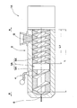
図1は、本実施形態のゴム押出機1を示す断面図である。図1に示されるように、本実施形態のゴム押出機1は、未加硫ゴムGを混練しながら上流側Aから下流側Bに向けて押し出している。ゴム押出機1は、略円筒状のバレル2と、バレル2内に配されたスクリュー3と、バレル2内の空気を吸引するためのベント4とを含んでいるのが望ましい。
図1は、本実施形態のゴム押出機1を示す断面図である。図1に示されるように、本実施形態のゴム押出機1は、未加硫ゴムGを混練しながら上流側Aから下流側Bに向けて押し出している。ゴム押出機1は、略円筒状のバレル2と、バレル2内に配されたスクリュー3と、バレル2内の空気を吸引するためのベント4とを含んでいるのが望ましい。
バレル2は、例えば、未加硫ゴムGの押出方向の上流側Aから下流側Bにかけて、略一定の内径dを有している。バレル2は、上流側Aの円周部に、未加硫ゴムGを投入するための投入口5を有するのが望ましい。また、バレル2は、下流側Bの端部に、未加硫ゴムGを吐出するための吐出口6を有するのが望ましい。
スクリュー3は、バレル2内の未加硫ゴムGを押し出すためのものである。スクリュー3は、スクリュー軸3aと、スクリュー軸3aからスクリュー3の径方向外側に突出する螺旋翼3bとを含んでいるのが望ましい。スクリュー軸3aは、例えば、バレル2の上流側Aに位置する駆動装置Mにより駆動される。
本実施形態のスクリュー3は、所定の全有効ねじ長さLと所定の外径Dとを有している。ここで、スクリュー3の全有効ねじ長さLは、螺旋翼3bが形成されている範囲の上流側Aの端部から下流側Bの端部までの軸方向長さである。また、スクリュー3の外径Dは、螺旋翼3bの最大外径である。
スクリュー3の全有効ねじ長さLとスクリュー3の外径Dとの比L/Dは、好ましくは、16~24である。比L/Dが16より小さいと、未加硫ゴムGを適切に搬送できず、投入口5から未加硫ゴムGがあふれるおそれがある。逆に、比L/Dが24より大きいと、ねじりトルクが大きくなり、スクリュー3が破損するおそれがある。
本実施形態のスクリュー3は、未加硫ゴムGの押出量を局部的に制限するダム部7と、ダム部7より上流側Aの第1スクリュー部8と、ダム部7より押出方向の下流側Bの第2スクリュー部9とを有している。このようなスクリュー3は、ダム部7において未加硫ゴムGを薄く引き延ばし、未加硫ゴムG内の揮発成分を気化し、当該揮発成分を除去し易い状態にすることができる。
本実施形態の第1スクリュー部8は、バレル2の投入口5からダム部7までの領域に位置している。また、本実施形態の第2スクリュー部9は、ダム部7からバレル2の吐出口6までの領域に位置している。
本実施形態のスクリュー軸3aは、ダム部7、第1スクリュー部8及び第2スクリュー部9を、一体的に連結している。また、本実施形態の螺旋翼3bは、第1スクリュー部8に位置する第1螺旋翼8aと、第2スクリュー部9に位置する第2螺旋翼9aとを含んでいる。
第1螺旋翼8aは、例えば、所定のリード角θ1を有し、スクリュー軸3aの軸方向にずれながら周方向に連続して形成されている。このような第1螺旋翼8aは、バレル2内の未加硫ゴムGを、投入口5からダム部7に向かって混練しながら押し出すことができる。
第1スクリュー部8の外径D1は、第1螺旋翼8aの外径である。本実施形態では、第1スクリュー部8の外径D1は、スクリュー3の外径Dに等しい。第1スクリュー部8の有効ねじ長さL1と第1スクリュー部8の外径D1との比L1/D1は、好ましくは、8~12である。比L1/D1が8より小さいと、未加硫ゴムGを適切に搬送できず、投入口5から未加硫ゴムGがあふれるおそれがある。逆に、比L1/D1が12より大きいと、後述する第2スクリュー部9の有効ねじ長さL2が相対的に小さくなり、第2スクリュー部9付近に位置するベント4が未加硫ゴムGで閉塞されるおそれがある。
第1スクリュー部8の有効ねじ長さL1は、第1螺旋翼8aが形成されている範囲の軸方向長さ、すなわち、ダム部7から第1螺旋翼8aの上流側Aの端部までの軸方向長さである。第1スクリュー部8の有効ねじ長さL1は、スクリュー3の全有効ねじ長さLの50%以上であるのが好ましい。第1スクリュー部8の有効ねじ長さL1をスクリュー3の全有効ねじ長さLの50%以上とすることで、第1スクリュー部8における未加硫ゴムGの搬送力が大幅に向上し、その結果、ダム部7の未加硫ゴムGの押出量を増加させることができる。このため、ゴム押出機1は、未加硫ゴムGの生産性を低下させるおそれがない。
また、第1スクリュー部8の有効ねじ長さL1は、スクリュー3の全有効ねじ長さLの60%以下であるのが好ましい。第1スクリュー部8の有効ねじ長さL1をスクリュー3の全有効ねじ長さLの60%以下とすることで、後述する第2スクリュー部9の有効ねじ長さL2が相対的に大きくなり、第2スクリュー部9付近に位置するベント4が未加硫ゴムGで閉塞されるおそれがない。
第2螺旋翼9aは、例えば、所定のリード角θ2を有し、スクリュー軸3aの軸方向にずれながら周方向に連続して形成されている。このような第2螺旋翼9aは、バレル2内の未加硫ゴムGを、ダム部7から吐出口6に向かって混練しながら押し出すことができる。
本実施形態の第2スクリュー部9のリード角θ2は、第1スクリュー部8のリード角θ1より大きい。このため、第2スクリュー部9は、ダム部7を通過した未加硫ゴムGを、効率よく吐出口6へ押し出すことができ、第2スクリュー部9付近に位置するベント4が未加硫ゴムGで閉塞され難くすることができる。
第2スクリュー部9の外径D2は、第2螺旋翼9aの外径である。本実施形態では、第2スクリュー部9の外径D2は、第1スクリュー部8の外径D1に等しく、かつ、スクリュー3の外径Dに等しい。
また、第2スクリュー部9の有効ねじ長さL2は、第2螺旋翼9aが形成されている範囲の軸方向長さ、すなわち、ダム部7から第2螺旋翼9aの下流側Bの端部までの軸方向長さである。第2スクリュー部9の有効ねじ長さL2は、スクリュー3の全有効ねじ長さLの35%以上であるのが好ましい。第2スクリュー部9の有効ねじ長さL2をスクリュー3の全有効ねじ長さLの35%以上とすることで、第2スクリュー部9付近に位置するベント4が未加硫ゴムGで閉塞されるおそれがない。
なお、本実施形態のスクリュー3の全有効ねじ長さLは、第1スクリュー部8の有効ねじ長さL1と、第2スクリュー部9の有効ねじ長さL2と、ダム部7の軸方向長さL3との和である。
本実施形態のダム部7は、スクリュー軸3aの外径を大きくしたものが例示されている。ダム部7の態様は、これに限定されず、未加硫ゴムGの押出量を局部的に制限するものであれば、周知の種々の態様が採用され得る。
本実施形態のベント4は、バレル2に形成されたベント口4aと、真空ポンプ4bと、ベント口4aと真空ポンプ4bとを接続する接続管4cとを含んでいる。このようなベント4は、バレル2内を負圧にすることができ、バレル2内の空気を吸引することができる。
ベント口4aは、ダム部7の下流側Bで、ダム部7に隣接して設けられるのが望ましい。このようなベント口4aを含むベント4は、ダム部7で薄く引き延ばされた未加硫ゴムGの揮発成分を、効率よく除去することができる。
図2は、他の実施形態のゴム押出機1Aを示す断面図である。上記実施形態と実質的に同一の要素は、同一の符号が付され、その説明が省略される。図2に示されるように、この実施形態のゴム押出機1Aは、略円筒状のバレル2と、バレル2内に配されたスクリュー3Aと、バレル2内の空気を吸引するためのベント4とを含んでいる。
この実施形態のスクリュー3Aは、未加硫ゴムGの押出量を局部的に制限するダム部7と、ダム部7より上流側Aの第1スクリュー部8Aと、ダム部7より押出方向の下流側Bの第2スクリュー部9Aとを有している。
この実施形態の第1スクリュー部8Aは、2条ねじスクリューで形成されている。第1スクリュー部8Aの有効ねじ長さL1は、スクリュー3Aの全有効ねじ長さLの50%~60%であるのが好ましい。このような第1スクリュー部8Aは、未加硫ゴムGをダム部7に向かって安定して押し出すことができ、未加硫ゴムGの第1スクリュー部8Aでの圧力を一定に保つことができる。
この実施形態の第2スクリュー部9Aは、少なくともベント4が形成される位置に対応する部分が、1条ねじスクリューで形成されている。このような第2スクリュー部9Aは、未加硫ゴムGを吐出口6に向かって効率よく押し出すことができ、粘度の高い未加硫ゴムGであっても、ベント4が未加硫ゴムGで閉塞されるおそれがない。
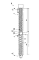
図3は、さらに他の実施形態のゴム押出機1Bを示す断面図である。上記実施形態と実質的に同一の要素は、同一の符号が付され、その説明が省略される。図3に示されるように、この実施形態のゴム押出機1Bは、略円筒状のバレル2と、バレル2内に配されたスクリュー3Bと、バレル2内の空気を吸引するためのベント4とを含んでいる。
なお、図1及び図2においては、理解を容易にするために、スクリュー3の外径D方向の寸法を誇張して示されていたが、図3では、スクリュー3Bの全有効ねじ長さLとスクリュー3Bの外径Dとの比L/Dが16の場合が示されている。
この実施形態のスクリュー3Bは、未加硫ゴムGの押出量を局部的に制限するダム部7と、ダム部7より上流側Aの第1スクリュー部8Bと、ダム部7より押出方向の下流側Bの第2スクリュー部9Bとを有している。
この実施形態の第1スクリュー部8Bは、2条ねじスクリューで形成されている。第1スクリュー部8Bの有効ねじ長さL1は、スクリュー3Bの全有効ねじ長さLの50%~60%であるのが好ましい。このような第1スクリュー部8Bは、未加硫ゴムGをダム部7に向かって安定して押し出すことができ、未加硫ゴムGの第1スクリュー部8Bでの圧力を一定に保つことができる。
この実施形態の第2スクリュー部9Bは、ダム部7から下流側Bに位置する吐出口6に向かって、少なくとも一部の範囲が、1条ねじスクリューで形成されている。1条ねじスクリューが形成される範囲のダム部7からの長さL4は、好ましくは、第2スクリュー部9Bの有効ねじ長さL2の30%~100%である。このような第2スクリュー部9Bは、ベント4近傍において、未加硫ゴムGを効率よく押し出すことができ、吐出口6近傍において、未加硫ゴムGを安定して押し出すことができる。
以上、本発明の特に好ましい実施形態について詳述したが、本発明は図示の実施形態に限定されることなく、種々の態様に変形して実施し得る。
1 ゴム押出機
2 バレル
3 スクリュー
4 ベント
5 投入口
6 吐出口
7 ダム部
8 第1スクリュー部
9 第2スクリュー部
G 未加硫ゴム
2 バレル
3 スクリュー
4 ベント
5 投入口
6 吐出口
7 ダム部
8 第1スクリュー部
9 第2スクリュー部
G 未加硫ゴム
Claims (10)
- 未加硫ゴムを混練しながら押し出すためのゴム押出機であって、
前記未加硫ゴムを投入するための投入口と前記未加硫ゴムを吐出するための吐出口とを有するバレルと、
前記バレル内に配されかつ前記未加硫ゴムを押し出すためのスクリューと、
前記バレル内の空気を吸引するためのベントとを含み、
前記スクリューは、前記未加硫ゴムの押出量を局部的に制限するダム部と、前記投入口から前記ダム部までの第1スクリュー部と、前記ダム部から前記吐出口までの第2スクリュー部とを有し、
前記第1スクリュー部の有効ねじ長さL1は、前記スクリューの全有効ねじ長さLの50%以上であるゴム押出機。 - 前記第1スクリュー部の前記有効ねじ長さL1は、前記スクリューの前記全有効ねじ長さLの60%以下である請求項1に記載のゴム押出機。
- 前記第2スクリュー部の有効ねじ長さL2は、前記スクリューの前記全有効ねじ長さLの35%以上である請求項1又は2に記載のゴム押出機。
- 前記スクリューの前記全有効ねじ長さLと前記スクリューの外径Dとの比L/Dは、16~24である請求項1~3のいずれかに記載のゴム押出機。
- 前記第1スクリュー部の前記有効ねじ長さL1と前記第1スクリュー部の外径D1との比L1/D1は、8~12である請求項1~4のいずれかに記載のゴム押出機。
- 前記第2スクリュー部は、少なくとも前記ベントが形成される位置に対応する部分が、1条ねじスクリューで形成される請求項1~5のいずれかに記載のゴム押出機。
- 前記第2スクリュー部は、前記ダム部から前記吐出口に向かって、前記第2スクリュー部の有効ねじ長さL2の30%~100%の範囲が、1条ねじスクリューで形成される請求項1~6のいずれかに記載のゴム押出機。
- 前記第1スクリュー部は、2条ねじスクリューで形成される請求項1~7のいずれかにゴム押出機。
- 未加硫ゴムを混練しながら押し出すためのゴム押出機用のスクリューであって、
前記未加硫ゴムの押出量を局部的に制限するダム部と、前記ダム部より前記未加硫ゴムの押出方向の上流側に位置する第1スクリュー部と、前記ダム部より前記未加硫ゴムの押出方向の下流側に位置する第2スクリュー部とを有し、
前記第1スクリュー部の有効ねじ長さL1は、前記第1スクリュー部、前記ダム部及び前記第2スクリュー部を含む全有効ねじ長さLの50%以上であるスクリュー。 - 前記第2スクリュー部は、前記ダム部から前記下流側に向かって、前記第2スクリュー部の有効ねじ長さL2の30%~100%の範囲が、1条ねじスクリューで形成される請求項9に記載のスクリュー。
Priority Applications (4)
| Application Number | Priority Date | Filing Date | Title |
|---|---|---|---|
| EP18810391.5A EP3623135A4 (en) | 2017-05-29 | 2018-05-16 | RUBBER EXTRUDER AND AUGER FOR IT |
| KR1020197036333A KR20200014316A (ko) | 2017-05-29 | 2018-05-16 | 고무 압출기 및 그 스크루 |
| CN201880030032.2A CN110603131A (zh) | 2017-05-29 | 2018-05-16 | 橡胶挤出机及其螺杆 |
| US16/610,273 US20200147564A1 (en) | 2017-05-29 | 2018-05-16 | Rubber extruder and screw for same |
Applications Claiming Priority (2)
| Application Number | Priority Date | Filing Date | Title |
|---|---|---|---|
| JP2017-105250 | 2017-05-29 | ||
| JP2017105250A JP6783189B2 (ja) | 2017-05-29 | 2017-05-29 | ゴム押出機及びそのスクリュー |
Publications (1)
| Publication Number | Publication Date |
|---|---|
| WO2018221219A1 true WO2018221219A1 (ja) | 2018-12-06 |
Family
ID=64454614
Family Applications (1)
| Application Number | Title | Priority Date | Filing Date |
|---|---|---|---|
| PCT/JP2018/018897 Ceased WO2018221219A1 (ja) | 2017-05-29 | 2018-05-16 | ゴム押出機及びそのスクリュー |
Country Status (6)
| Country | Link |
|---|---|
| US (1) | US20200147564A1 (ja) |
| EP (1) | EP3623135A4 (ja) |
| JP (1) | JP6783189B2 (ja) |
| KR (1) | KR20200014316A (ja) |
| CN (1) | CN110603131A (ja) |
| WO (1) | WO2018221219A1 (ja) |
Families Citing this family (4)
| Publication number | Priority date | Publication date | Assignee | Title |
|---|---|---|---|---|
| CN111633947B (zh) * | 2019-03-01 | 2023-11-10 | 住友橡胶工业株式会社 | 橡胶挤出机以及橡胶挤出方法 |
| DE102023206398A1 (de) * | 2023-07-06 | 2025-01-09 | Continental Reifen Deutschland Gmbh | Extruder mit optimiertem Schneckendesign |
| DE102023206399A1 (de) | 2023-07-06 | 2025-01-09 | Continental Reifen Deutschland Gmbh | Extruder mit optimiertem Schneckendesign |
| DE102023212679A1 (de) | 2023-12-14 | 2025-06-18 | Continental Reifen Deutschland Gmbh | Doppelschneckenextruder mit Sensoreinheit |
Citations (4)
| Publication number | Priority date | Publication date | Assignee | Title |
|---|---|---|---|---|
| JPS58108118A (ja) * | 1981-12-22 | 1983-06-28 | Japan Steel Works Ltd:The | 単軸押出成形機用スクリユ |
| JP2004237715A (ja) * | 2002-12-11 | 2004-08-26 | Sumitomo Rubber Ind Ltd | 押出機および押出方法 |
| JP2005161808A (ja) | 2003-12-05 | 2005-06-23 | Canon Chemicals Inc | 押出し成形機及び押出し成形方法及びゴムローラ |
| JP2016141135A (ja) * | 2015-02-05 | 2016-08-08 | 富士ゼロックス株式会社 | ゴムロールの製造方法、及びゴムロールの製造装置 |
-
2017
- 2017-05-29 JP JP2017105250A patent/JP6783189B2/ja active Active
-
2018
- 2018-05-16 WO PCT/JP2018/018897 patent/WO2018221219A1/ja not_active Ceased
- 2018-05-16 EP EP18810391.5A patent/EP3623135A4/en not_active Withdrawn
- 2018-05-16 CN CN201880030032.2A patent/CN110603131A/zh active Pending
- 2018-05-16 KR KR1020197036333A patent/KR20200014316A/ko not_active Ceased
- 2018-05-16 US US16/610,273 patent/US20200147564A1/en not_active Abandoned
Patent Citations (4)
| Publication number | Priority date | Publication date | Assignee | Title |
|---|---|---|---|---|
| JPS58108118A (ja) * | 1981-12-22 | 1983-06-28 | Japan Steel Works Ltd:The | 単軸押出成形機用スクリユ |
| JP2004237715A (ja) * | 2002-12-11 | 2004-08-26 | Sumitomo Rubber Ind Ltd | 押出機および押出方法 |
| JP2005161808A (ja) | 2003-12-05 | 2005-06-23 | Canon Chemicals Inc | 押出し成形機及び押出し成形方法及びゴムローラ |
| JP2016141135A (ja) * | 2015-02-05 | 2016-08-08 | 富士ゼロックス株式会社 | ゴムロールの製造方法、及びゴムロールの製造装置 |
Non-Patent Citations (1)
| Title |
|---|
| See also references of EP3623135A4 |
Also Published As
| Publication number | Publication date |
|---|---|
| CN110603131A (zh) | 2019-12-20 |
| KR20200014316A (ko) | 2020-02-10 |
| EP3623135A1 (en) | 2020-03-18 |
| JP2018199272A (ja) | 2018-12-20 |
| EP3623135A4 (en) | 2021-02-17 |
| JP6783189B2 (ja) | 2020-11-11 |
| US20200147564A1 (en) | 2020-05-14 |
Similar Documents
| Publication | Publication Date | Title |
|---|---|---|
| JP6783189B2 (ja) | ゴム押出機及びそのスクリュー | |
| JP2020520825A5 (ja) | ||
| JP4746014B2 (ja) | 溶融混練脱揮押出機 | |
| US11104053B2 (en) | Extruder | |
| US20160222964A1 (en) | Fuel pump | |
| WO2016075993A1 (ja) | 流動体搬送装置 | |
| TWI873231B (zh) | 螺杆、擠出機及擠出方法 | |
| WO2015107422A4 (en) | Mixing section for a plastic extrusion screw | |
| MX2020011352A (es) | Maquina mezcladora y amasadora. | |
| EP3702125A3 (en) | Rubber extruder and method for extruding rubber | |
| JP6202624B2 (ja) | 2軸押出機 | |
| JP6615132B2 (ja) | 真空ポンプシステム | |
| EP2829731B1 (en) | Gear pump | |
| JP6844202B2 (ja) | ゴム押出機 | |
| JP2018162859A5 (ja) | ||
| JP6736972B2 (ja) | ゴム押出装置 | |
| CN113799363B (zh) | 具有自动排气功能的挤出设备 | |
| WO2008140071A1 (ja) | シングルスクリュー圧縮機 | |
| JP6790466B2 (ja) | ゴム押出機 | |
| JP7243111B2 (ja) | ダイプレート及びゴム押出装置 | |
| US20180015434A1 (en) | Stuffing screw | |
| JP6931195B2 (ja) | 押出装置 | |
| CN113829607B (zh) | 多段排气式挤出机及其使用方法 | |
| CN216100335U (zh) | 多段排气式挤出机 | |
| WO2020003898A1 (ja) | スクリュ式押出機 |
Legal Events
| Date | Code | Title | Description |
|---|---|---|---|
| 121 | Ep: the epo has been informed by wipo that ep was designated in this application |
Ref document number: 18810391 Country of ref document: EP Kind code of ref document: A1 |
|
| NENP | Non-entry into the national phase |
Ref country code: DE |
|
| ENP | Entry into the national phase |
Ref document number: 20197036333 Country of ref document: KR Kind code of ref document: A |
|
| ENP | Entry into the national phase |
Ref document number: 2018810391 Country of ref document: EP Effective date: 20191210 |