WO2020003898A1 - スクリュ式押出機 - Google Patents
スクリュ式押出機 Download PDFInfo
- Publication number
- WO2020003898A1 WO2020003898A1 PCT/JP2019/021875 JP2019021875W WO2020003898A1 WO 2020003898 A1 WO2020003898 A1 WO 2020003898A1 JP 2019021875 W JP2019021875 W JP 2019021875W WO 2020003898 A1 WO2020003898 A1 WO 2020003898A1
- Authority
- WO
- WIPO (PCT)
- Prior art keywords
- downstream end
- flight
- screw
- clearance
- casing
- Prior art date
- Legal status (The legal status is an assumption and is not a legal conclusion. Google has not performed a legal analysis and makes no representation as to the accuracy of the status listed.)
- Ceased
Links
Images





Classifications
-
- B—PERFORMING OPERATIONS; TRANSPORTING
- B29—WORKING OF PLASTICS; WORKING OF SUBSTANCES IN A PLASTIC STATE IN GENERAL
- B29C—SHAPING OR JOINING OF PLASTICS; SHAPING OF MATERIAL IN A PLASTIC STATE, NOT OTHERWISE PROVIDED FOR; AFTER-TREATMENT OF THE SHAPED PRODUCTS, e.g. REPAIRING
- B29C48/00—Extrusion moulding, i.e. expressing the moulding material through a die or nozzle which imparts the desired form; Apparatus therefor
- B29C48/25—Component parts, details or accessories; Auxiliary operations
- B29C48/36—Means for plasticising or homogenising the moulding material or forcing it through the nozzle or die
- B29C48/50—Details of extruders
- B29C48/505—Screws
- B29C48/52—Screws with an outer diameter varying along the longitudinal axis, e.g. for obtaining different thread clearance
-
- B—PERFORMING OPERATIONS; TRANSPORTING
- B29—WORKING OF PLASTICS; WORKING OF SUBSTANCES IN A PLASTIC STATE IN GENERAL
- B29C—SHAPING OR JOINING OF PLASTICS; SHAPING OF MATERIAL IN A PLASTIC STATE, NOT OTHERWISE PROVIDED FOR; AFTER-TREATMENT OF THE SHAPED PRODUCTS, e.g. REPAIRING
- B29C48/00—Extrusion moulding, i.e. expressing the moulding material through a die or nozzle which imparts the desired form; Apparatus therefor
- B29C48/25—Component parts, details or accessories; Auxiliary operations
- B29C48/36—Means for plasticising or homogenising the moulding material or forcing it through the nozzle or die
- B29C48/50—Details of extruders
- B29C48/505—Screws
- B29C48/52—Screws with an outer diameter varying along the longitudinal axis, e.g. for obtaining different thread clearance
- B29C48/525—Conical screws
-
- B—PERFORMING OPERATIONS; TRANSPORTING
- B29—WORKING OF PLASTICS; WORKING OF SUBSTANCES IN A PLASTIC STATE IN GENERAL
- B29B—PREPARATION OR PRETREATMENT OF THE MATERIAL TO BE SHAPED; MAKING GRANULES OR PREFORMS; RECOVERY OF PLASTICS OR OTHER CONSTITUENTS OF WASTE MATERIAL CONTAINING PLASTICS
- B29B7/00—Mixing; Kneading
- B29B7/30—Mixing; Kneading continuous, with mechanical mixing or kneading devices
- B29B7/34—Mixing; Kneading continuous, with mechanical mixing or kneading devices with movable mixing or kneading devices
- B29B7/38—Mixing; Kneading continuous, with mechanical mixing or kneading devices with movable mixing or kneading devices rotary
- B29B7/46—Mixing; Kneading continuous, with mechanical mixing or kneading devices with movable mixing or kneading devices rotary with more than one shaft
- B29B7/48—Mixing; Kneading continuous, with mechanical mixing or kneading devices with movable mixing or kneading devices rotary with more than one shaft with intermeshing devices, e.g. screws
- B29B7/484—Mixing; Kneading continuous, with mechanical mixing or kneading devices with movable mixing or kneading devices rotary with more than one shaft with intermeshing devices, e.g. screws with two shafts provided with screws, e.g. one screw being shorter than the other
-
- B—PERFORMING OPERATIONS; TRANSPORTING
- B29—WORKING OF PLASTICS; WORKING OF SUBSTANCES IN A PLASTIC STATE IN GENERAL
- B29B—PREPARATION OR PRETREATMENT OF THE MATERIAL TO BE SHAPED; MAKING GRANULES OR PREFORMS; RECOVERY OF PLASTICS OR OTHER CONSTITUENTS OF WASTE MATERIAL CONTAINING PLASTICS
- B29B7/00—Mixing; Kneading
- B29B7/30—Mixing; Kneading continuous, with mechanical mixing or kneading devices
- B29B7/34—Mixing; Kneading continuous, with mechanical mixing or kneading devices with movable mixing or kneading devices
- B29B7/38—Mixing; Kneading continuous, with mechanical mixing or kneading devices with movable mixing or kneading devices rotary
- B29B7/46—Mixing; Kneading continuous, with mechanical mixing or kneading devices with movable mixing or kneading devices rotary with more than one shaft
- B29B7/48—Mixing; Kneading continuous, with mechanical mixing or kneading devices with movable mixing or kneading devices rotary with more than one shaft with intermeshing devices, e.g. screws
- B29B7/488—Parts, e.g. casings, sealings; Accessories, e.g. flow controlling or throttling devices
-
- B—PERFORMING OPERATIONS; TRANSPORTING
- B29—WORKING OF PLASTICS; WORKING OF SUBSTANCES IN A PLASTIC STATE IN GENERAL
- B29B—PREPARATION OR PRETREATMENT OF THE MATERIAL TO BE SHAPED; MAKING GRANULES OR PREFORMS; RECOVERY OF PLASTICS OR OTHER CONSTITUENTS OF WASTE MATERIAL CONTAINING PLASTICS
- B29B7/00—Mixing; Kneading
- B29B7/30—Mixing; Kneading continuous, with mechanical mixing or kneading devices
- B29B7/58—Component parts, details or accessories; Auxiliary operations
- B29B7/60—Component parts, details or accessories; Auxiliary operations for feeding, e.g. end guides for the incoming material
-
- B—PERFORMING OPERATIONS; TRANSPORTING
- B29—WORKING OF PLASTICS; WORKING OF SUBSTANCES IN A PLASTIC STATE IN GENERAL
- B29B—PREPARATION OR PRETREATMENT OF THE MATERIAL TO BE SHAPED; MAKING GRANULES OR PREFORMS; RECOVERY OF PLASTICS OR OTHER CONSTITUENTS OF WASTE MATERIAL CONTAINING PLASTICS
- B29B7/00—Mixing; Kneading
- B29B7/74—Mixing; Kneading using other mixers or combinations of mixers, e.g. of dissimilar mixers ; Plant
- B29B7/7476—Systems, i.e. flow charts or diagrams; Plants
- B29B7/7495—Systems, i.e. flow charts or diagrams; Plants for mixing rubber
-
- B—PERFORMING OPERATIONS; TRANSPORTING
- B29—WORKING OF PLASTICS; WORKING OF SUBSTANCES IN A PLASTIC STATE IN GENERAL
- B29C—SHAPING OR JOINING OF PLASTICS; SHAPING OF MATERIAL IN A PLASTIC STATE, NOT OTHERWISE PROVIDED FOR; AFTER-TREATMENT OF THE SHAPED PRODUCTS, e.g. REPAIRING
- B29C48/00—Extrusion moulding, i.e. expressing the moulding material through a die or nozzle which imparts the desired form; Apparatus therefor
- B29C48/03—Extrusion moulding, i.e. expressing the moulding material through a die or nozzle which imparts the desired form; Apparatus therefor characterised by the shape of the extruded material at extrusion
- B29C48/07—Flat, e.g. panels
-
- B—PERFORMING OPERATIONS; TRANSPORTING
- B29—WORKING OF PLASTICS; WORKING OF SUBSTANCES IN A PLASTIC STATE IN GENERAL
- B29C—SHAPING OR JOINING OF PLASTICS; SHAPING OF MATERIAL IN A PLASTIC STATE, NOT OTHERWISE PROVIDED FOR; AFTER-TREATMENT OF THE SHAPED PRODUCTS, e.g. REPAIRING
- B29C48/00—Extrusion moulding, i.e. expressing the moulding material through a die or nozzle which imparts the desired form; Apparatus therefor
- B29C48/03—Extrusion moulding, i.e. expressing the moulding material through a die or nozzle which imparts the desired form; Apparatus therefor characterised by the shape of the extruded material at extrusion
- B29C48/07—Flat, e.g. panels
- B29C48/08—Flat, e.g. panels flexible, e.g. films
-
- B—PERFORMING OPERATIONS; TRANSPORTING
- B29—WORKING OF PLASTICS; WORKING OF SUBSTANCES IN A PLASTIC STATE IN GENERAL
- B29C—SHAPING OR JOINING OF PLASTICS; SHAPING OF MATERIAL IN A PLASTIC STATE, NOT OTHERWISE PROVIDED FOR; AFTER-TREATMENT OF THE SHAPED PRODUCTS, e.g. REPAIRING
- B29C48/00—Extrusion moulding, i.e. expressing the moulding material through a die or nozzle which imparts the desired form; Apparatus therefor
- B29C48/25—Component parts, details or accessories; Auxiliary operations
- B29C48/251—Design of extruder parts, e.g. by modelling based on mathematical theories or experiments
-
- B—PERFORMING OPERATIONS; TRANSPORTING
- B29—WORKING OF PLASTICS; WORKING OF SUBSTANCES IN A PLASTIC STATE IN GENERAL
- B29C—SHAPING OR JOINING OF PLASTICS; SHAPING OF MATERIAL IN A PLASTIC STATE, NOT OTHERWISE PROVIDED FOR; AFTER-TREATMENT OF THE SHAPED PRODUCTS, e.g. REPAIRING
- B29C48/00—Extrusion moulding, i.e. expressing the moulding material through a die or nozzle which imparts the desired form; Apparatus therefor
- B29C48/25—Component parts, details or accessories; Auxiliary operations
- B29C48/30—Extrusion nozzles or dies
- B29C48/35—Extrusion nozzles or dies with rollers
-
- B—PERFORMING OPERATIONS; TRANSPORTING
- B29—WORKING OF PLASTICS; WORKING OF SUBSTANCES IN A PLASTIC STATE IN GENERAL
- B29C—SHAPING OR JOINING OF PLASTICS; SHAPING OF MATERIAL IN A PLASTIC STATE, NOT OTHERWISE PROVIDED FOR; AFTER-TREATMENT OF THE SHAPED PRODUCTS, e.g. REPAIRING
- B29C48/00—Extrusion moulding, i.e. expressing the moulding material through a die or nozzle which imparts the desired form; Apparatus therefor
- B29C48/25—Component parts, details or accessories; Auxiliary operations
- B29C48/36—Means for plasticising or homogenising the moulding material or forcing it through the nozzle or die
- B29C48/395—Means for plasticising or homogenising the moulding material or forcing it through the nozzle or die using screws surrounded by a cooperating barrel, e.g. single screw extruders
- B29C48/40—Means for plasticising or homogenising the moulding material or forcing it through the nozzle or die using screws surrounded by a cooperating barrel, e.g. single screw extruders using two or more parallel screws or at least two parallel non-intermeshing screws, e.g. twin screw extruders
-
- B—PERFORMING OPERATIONS; TRANSPORTING
- B29—WORKING OF PLASTICS; WORKING OF SUBSTANCES IN A PLASTIC STATE IN GENERAL
- B29C—SHAPING OR JOINING OF PLASTICS; SHAPING OF MATERIAL IN A PLASTIC STATE, NOT OTHERWISE PROVIDED FOR; AFTER-TREATMENT OF THE SHAPED PRODUCTS, e.g. REPAIRING
- B29C48/00—Extrusion moulding, i.e. expressing the moulding material through a die or nozzle which imparts the desired form; Apparatus therefor
- B29C48/25—Component parts, details or accessories; Auxiliary operations
- B29C48/36—Means for plasticising or homogenising the moulding material or forcing it through the nozzle or die
- B29C48/50—Details of extruders
- B29C48/505—Screws
- B29C48/535—Screws with thread pitch varying along the longitudinal axis
-
- B—PERFORMING OPERATIONS; TRANSPORTING
- B29—WORKING OF PLASTICS; WORKING OF SUBSTANCES IN A PLASTIC STATE IN GENERAL
- B29C—SHAPING OR JOINING OF PLASTICS; SHAPING OF MATERIAL IN A PLASTIC STATE, NOT OTHERWISE PROVIDED FOR; AFTER-TREATMENT OF THE SHAPED PRODUCTS, e.g. REPAIRING
- B29C48/00—Extrusion moulding, i.e. expressing the moulding material through a die or nozzle which imparts the desired form; Apparatus therefor
- B29C48/25—Component parts, details or accessories; Auxiliary operations
- B29C48/36—Means for plasticising or homogenising the moulding material or forcing it through the nozzle or die
- B29C48/50—Details of extruders
- B29C48/68—Barrels or cylinders
- B29C48/682—Barrels or cylinders for twin screws
-
- B—PERFORMING OPERATIONS; TRANSPORTING
- B29—WORKING OF PLASTICS; WORKING OF SUBSTANCES IN A PLASTIC STATE IN GENERAL
- B29L—INDEXING SCHEME ASSOCIATED WITH SUBCLASS B29C, RELATING TO PARTICULAR ARTICLES
- B29L2007/00—Flat articles, e.g. films or sheets
- B29L2007/002—Panels; Plates; Sheets
-
- B—PERFORMING OPERATIONS; TRANSPORTING
- B29—WORKING OF PLASTICS; WORKING OF SUBSTANCES IN A PLASTIC STATE IN GENERAL
- B29L—INDEXING SCHEME ASSOCIATED WITH SUBCLASS B29C, RELATING TO PARTICULAR ARTICLES
- B29L2030/00—Pneumatic or solid tyres or parts thereof
Definitions
- the present invention relates to a screw type extruder for extruding a kneaded material.
- an extruder In an automobile tire manufacturing process, an extruder is used, which is installed under a rubber kneader as a raw material of the tire and continuously extrudes rubber (kneaded material) supplied from the kneader into a sheet. Has been.
- Patent Document 1 discloses a kneaded material transfer device in which a gap is formed between a housing disposed so as to surround a distal end portion of a tapered screw and the tapered screw.
- the rotation of the tapered screw allows a part of the input material to be transferred to the tip side of the casing to escape into the gap, so that the pressure applied to the material is reduced, and the pressure increase and the heat generation of the material due to the pressing force are suppressed.
- the flow (movement) of the input raw material at the portion where the raw material meshes with the screw is facilitated, the load is reduced, the extrusion amount is increased, and the raw material can be smoothly supplied to the compression section.
- the size of the lead angle of the screw blade at the position of the compression portion is set smaller than the size of the lead angle of the screw blade at the position of the hopper portion, and the screw blade is positioned at the position of the compression portion.
- a twin screw extruder having two or more turns is disclosed. At the position of the hopper part, the function to bite the bulk material supplied from the material input port and supply it to the compression part, and at the position of the compression part, to compress the material and to press the material required to push out the material from the material discharge port. In addition, a function of suppressing the backflow of the material and securing a processing amount is exerted.
- Patent Document 1 although the kneading performance is improved by increasing the extrusion amount, the boosting ability in the bank portion is reduced.
- Patent Document 2 it is possible to increase the pressurizing capacity in the bank by suppressing the backflow of the material, but the conveying capacity is reduced, and a pressurizing effect can be obtained depending on the production capacity of the screw type extruder. May not be.
- An object of the present invention is to provide a screw-type extruder capable of improving the pressurizing capacity in a bank section.
- the present invention includes a pair of screws, a casing accommodating the pair of screws, provided with a material input port on the upstream side, and a roller die for extruding the material into a sheet on the downstream side of the casing.
- the screw has a shaft portion, and a spiral flight portion provided on an outer peripheral surface of the shaft portion, and the flight portion includes: The radial distance from the surface of the shaft portion to the tip of the flight portion is shaped so as to gradually decrease toward the downstream end in the extrusion direction of the kneaded material, the casing has a tapered shape, and the input port In the range from the downstream end of the flight portion to the downstream end of the flight portion, the clearance between the top portion of the flight portion and the inner wall surface of the casing at the downstream end of the charging port, Kicking, characterized in that it is greater than the clearance.
- the clearance at the downstream end of the inlet is made larger than the clearance at other portions.
- FIG. 9 is an explanatory diagram showing an analysis result of boosting ability. It is sectional drawing of the casing downstream part in the modification of 3rd Embodiment.
- the screw extruder according to the first embodiment of the present invention extrudes a kneaded material.
- the screw type extruder is a screw extruder with a roller die for extruding a kneaded product of a polymer material such as rubber into a sheet.
- the screw type extruder 1 has a pair of screws 2 and 3 and a casing 4 as shown in FIG.
- the pair of screws 2 and 3 extrude the kneaded material in the left direction in FIG. 1 and are arranged side by side in a direction perpendicular to the paper surface of FIG.
- the number of screw threads of each of the screws 2 and 3 is one.
- the screws 2 and 3 each have a shaft portion 6 and a flight portion 7.
- the shaft 6 has a shape whose diameter gradually decreases toward the downstream end in the extrusion direction of the kneaded material.
- the flight portion 7 is provided on the outer peripheral surface of the shaft portion 6 and has a spiral shape.
- the flight portion 7 has a smaller radial distance from the surface of the shaft portion 6 of the screw 2 or 3 to the tip of the flight portion 7 as the flight portion 7 is closer to the downstream end in the extrusion direction of the kneaded material. In the direction toward the downstream end.
- the screws 2 and 3 have the same shape and dimensions except that the twist angles of the flight portions 7 are opposite to each other.
- the screws 2 and 3 are connected so as to rotate in opposite directions to each other, and are rotated at the same rotational speed by one driving unit (not shown).
- the casing 4 has a tapered shape and accommodates the pair of screws 2 and 3.
- a pair of upper and lower rollers 8 and 9 are disposed in front of the casing 4 in the direction of extruding the kneaded material.
- the portion between the casing 4 and the rollers 8, 9 is called a bank portion 10, and the kneaded material extruded by the screws 2, 3 accumulates in the bank portion 10.
- rollers 8 and 9 are connected so as to rotate in opposite directions to each other, and are rotated at the same rotational speed by one driving unit (not shown).
- the rollers 8 and 9 are for rolling the kneaded material into a sheet (sheet 50), and are called roller dies.
- a material (kneaded material) inlet 11 is provided on the upstream side of the casing 4 in the direction of extruding the kneaded material.
- the casing 4 has a casing upstream portion 13 in which the charging port 11 is provided at an upper portion, and a casing downstream portion 14 whose periphery is surrounded by a wall surface.
- the kneaded material such as rubber supplied to the charging port 11 from above is pushed out to the bank 10 by the screws 2 and 3 rotating in opposite directions, and then passes between the rollers 8 and 9 to form a sheet. Molded.
- the screws 2 and 3 in the casing downstream portion 14 are divided into three regions 1 to 3 for each pitch. Since the screws 2 and 3 have a tapered shape, the transport capacity decreases as the position becomes closer to the downstream side. Therefore, the transport capacity is lower in the area 1 than in the area 2. On the other hand, a part of the region 3 protrudes from the casing downstream portion 14, and a sufficient amount of the kneaded material cannot be supplied to the region 3 only by the flight portion 7, and the region 3 is not filled. Therefore, the maximum transport capacity cannot be exhibited. Further, depending on the operating conditions, the supply amount of the kneaded material to the region 2 may be insufficient, and the region 2 may be in a non-full state.
- FIG. 2 is a sectional view of the casing downstream portion 14 in the conventional screw shape. Assuming that the clearance between the top of the flight section 7 and the inner wall surface of the casing 4 is clearance, the clearance is constant in a range from the downstream end 11a of the inlet 11 to the downstream end of the flight section 7 shown in FIG. is there. That is, a clearance D2 at the downstream end 11a of the input port 11, a clearance D1 at the downstream end of the flight section 7, and a clearance D3 at an intermediate portion between the downstream end 11a of the input port 11 and the downstream end of the flight section 7.
- the strain rate (shear rate) is obtained by dividing the rotation speed of the tip of the flight section 7 by the clearance.
- rubber has a characteristic that the viscosity (viscosity) decreases as the strain rate increases. In other words, for the same strain rate, the greater the clearance, the higher the viscosity of the rubber.
- FIG. 4 which is a schematic view of the casing downstream portion 14, the center of the downstream end of the casing 4 is set to the origin 0, the Z coordinate is taken in the screw axis direction, and the X coordinate is taken in the radial direction of the casing 4.
- FIG. 5 shows the relationship between the clearance in the screw axis direction and the viscosity in the conventional screw shape.
- the clearance ⁇ is constant from the downstream end (origin 0) of the casing 4 to the downstream end 11a of the inlet 11.
- FIG. 6 which is a cross-sectional view of the downstream portion of the casing
- the downstream end of the charging port 11 is located in a range from the downstream end 11a of the charging port 11 to the downstream end of the flight portion 7.
- the clearance D2 in 11a is made larger than the clearance in other parts.
- the broken line) is a straight line
- the inner wall surface (solid line) of the casing 4 is also a straight line.
- FIG. 7 shows the relationship between the clearance in the screw axis direction and the viscosity in the screw shape of the present embodiment using the coordinates in FIG.
- the clearance ⁇ increases from the downstream end (origin 0) of the casing 4 toward the downstream end 11a of the inlet 11. Therefore, at the downstream end 11a of the charging port 11, the rotation speed of the tip of the flight section 7 is smaller than in the conventional screw shape, and the increase in the strain rate is suppressed.
- the viscosity ⁇ of the material is maintained higher at the downstream end 11a of the inlet 11 as compared with the conventional screw shape having a constant clearance. That is, the distribution of the viscosity ⁇ indicated by the broken line in FIG.
- the clearance gradually increases from the downstream end of the flight section 7 to the downstream end 11a of the charging port 11, so that the clearance in the bank section 10 is smaller than in the case where the clearance is discontinuous.
- the boosting ability can be further improved. This is because the increase in the viscosity of the rubber in the clearance suppresses the leakage of the rubber from the clearance.
- the viscosity of the material is maintained at a higher level at the downstream end 11a of the inlet 11 than in a configuration in which the clearance is constant, so that material leakage to the inlet 11 is suppressed, and the transport efficiency is improved.
- the boosting ability in the bank unit 10 can be improved.
- FIG. 8 is a cross-sectional view of the casing downstream portion 14, the screw type extruder 101 of the present embodiment has a clearance D3 at an intermediate portion between the downstream end 11a of the charging port 11 and the downstream end of the flight portion 7. Is smaller than the clearance D1 at the downstream end of the flight section 7.
- a broken line) is a curve
- an inner wall surface (solid line) of the casing 4 is a straight line.
- FIG. 9 shows the relationship between the clearance in the screw axis direction and the viscosity in the screw shape of the present embodiment using the coordinates shown in FIG.
- the clearance ⁇ decreases from the downstream end (origin 0) of the casing 4 toward the intermediate portion, and the clearance ⁇ increases from the intermediate portion toward the downstream end 11a of the inlet 11. Therefore, the viscosity ⁇ of the material increases from the downstream end (origin 0) of the casing 4 toward the intermediate portion, and the viscosity ⁇ of the material decreases from the intermediate portion toward the downstream end 11a of the charging port 11.
- the strain rate at the intermediate portion is smaller than that of the screw extruder 1 of the first embodiment. Becomes smaller. As a result, the viscosity of the material is maintained higher in the intermediate portion than in the screw extruder 1 of the first embodiment, so that material leakage from the intermediate portion to the upstream side is suppressed, and the transport efficiency is further improved. . Thereby, the boosting capability of the bank unit 10 can be further improved.
- the flight portion 7 at the downstream end 11a of the inlet 11 is increased. Need to be low. Therefore, as compared with the case where the clearance is constant, the volumes V1 to V3 for each pitch are reduced, and the transport capability is reduced.
- the vertices of the flight part 7 are connected from the downstream end 11 a of the inlet 11 to the downstream end of the flight part 7 in a radial cross-sectional view of the shaft part 6. Make virtual lines curved. As a result, the height of the flight section 7 in the middle section is maintained high. As a result, compared to the screw type extruder 1 of the first embodiment, the volumes V1 to V3 for each pitch are larger. That is, V1 of the present embodiment is larger than V1 of the first embodiment, V2 of the present embodiment is larger than V2 of the first embodiment, and V3 of the present embodiment is larger than V3 of the first embodiment. Therefore, the transfer capacity can be improved.
- the center of the bottom of the top of the downstream end of the flight portion 7 of the screws 2 and 3 is defined as the origin 0, and the x coordinate is taken along the surface of the shaft 6 of the screws 2 and 3, The y-coordinate is taken in a direction perpendicular to the surface of No. 6.
- the x-coordinate of the top of the downstream end of the flight section 7 is 0, the x-coordinate of the top on the upstream side by one rotation from the top of the downstream end of the flight section 7 is X 1 , and the x-coordinate of the top of the downstream end of the flight section 7 is 2
- the x coordinate of the top on the upstream side by rotation is X 2
- the x coordinate of the top on the upstream side by three rotations from the top on the downstream end of the flight section 7 is X 3 .
- the height of the top of the downstream end of the flight section 7 is Y 0
- the height of the top of the downstream end of the flight section 7 by one rotation from the top is Y 1
- the height of the downstream end of the flight section 7 is Y 1
- the height of the top two turns upstream from the top is Y 2
- the height of the top three turns upstream from the top of the downstream end of the flight section 7 is Y 3 .
- the inclination at the downstream end of the flight section 7 is b
- the inclination at the top three rotations upstream from the top of the downstream end of the flight section 7 is 2aX 3 + b.
- the slope of the quadratic curve is greater than the slope of the straight line (Y 3 ⁇ Y 0 ) / X 3 at the downstream end of the flight section 7 and at the top 3 rotations upstream from the top of the downstream end of the flight section 7. , The inclination of the straight line (Y 3 ⁇ Y 0 ) / X 3 . Therefore, the relationship of b> (Y 3 ⁇ Y 0 ) / X 3 > 2aX 3 + b is established.
- FIG. 10 shows the result of a simple calculation of the boosting capacity based on the screw shape factor.
- the inclination of the flight height refers to the inclination of a straight line connecting the vertices of the flight part 7 along the axial direction of the screws 2 and 3.
- the inclination ratio of the flight height is 1.0, and as the clearance D2 at the downstream end 11a of the inlet 11 becomes larger than the clearance D1 at the downstream end of the flight section 7, the flight height increases. The value of the slope ratio decreases.
- the inclination of the flight height is approximately proportional to the pressure ratio and the transfer capability ratio, and the pressure ratio and the transfer capability ratio are in a trade-off relationship.
- the pressure ratio is about 7 times while the transfer capacity is maintained at the same level as the conventional one. From this, it can be seen that the transport capacity is improved to the same level as the conventional one while the boosting capacity in the bank unit 10 is improved.
- the clearance D3 at the intermediate portion between the downstream end 11a of the charging port 11 and the downstream end of the flight portion 7 is located downstream of the flight portion 7.
- the clearance is smaller than the clearance D1 at the side end.
- the strain rate in the intermediate portion is smaller than that of the screw type extruder 1 of the first embodiment.
- the viscosity of the material is maintained higher in the intermediate portion than in the screw extruder 1 of the first embodiment, so that material leakage from the intermediate portion to the upstream side is suppressed, and the transport efficiency is further improved. .
- the boosting ability in the bank portion can be further improved.
- a virtual line connecting the vertices of the flight portion 7 from the downstream end 11a of the inlet 11 to the downstream end of the flight portion 7 is a curve.
- the volumes V1 to V3 for each screw pitch are smaller than those in the case where the clearance is constant, and the transfer capacity is reduced. Therefore, in a radial cross-sectional view of the shaft portion 6, a virtual line connecting the vertices of the flight portion 7 from the downstream end 11a of the inlet 11 to the downstream end of the flight portion 7 is curved. As a result, the height of the flight section 7 in the middle section is maintained high. As a result, compared to the screw type extruder 1 of the first embodiment, the volume V1 to V3 for each pitch is increased, so that the transfer capacity can be improved.
- the inner wall surface of the casing 4 is straight from the downstream end 11a of the charging port 11 to the downstream end of the flight portion 7. Thereby, the casing 4 can be easily formed.
- FIG. 11 which is a cross-sectional view of the casing downstream portion 14, the shaft portion 6 is viewed from the downstream end 11 a of the charging port 11 in a radial cross-sectional view.
- An imaginary line (dashed line) connecting the vertices of the flight unit 7 may be a straight line over the downstream end of the flight unit 7, and an inner wall surface (solid line) of the casing 4 may be a curve.
- the clearance continuously changes from the downstream end 11 a of the inlet 11 to the downstream end of the flight section 7.
- the inner wall surface of the casing 4 is a quadratic curve, but the curve is not limited to this.
- a virtual line (dashed line) connecting the vertices of the flight unit 7 may be a curve.
- the center of the bottom of the top of the downstream end of the flight portion 7 of the screw 2, 3 is defined as the origin 0, and the x coordinate is taken along the surface of the shaft portion 6 of the screw 2, 3. Take the y coordinate in the direction perpendicular to.
- the x-coordinate of the top of the downstream end of the flight section 7 is 0, the x-coordinate of the top on the upstream side by one rotation from the top of the downstream end of the flight section 7 is X 1 , and the x-coordinate of the top of the downstream end of the flight section 7 is 2
- the x coordinate of the top on the upstream side by rotation is X 2
- the x coordinate of the top on the upstream side by three rotations from the top on the downstream end of the flight section 7 is X 3 .
- the height of the top of the downstream end of the flight section 7 is Y 0
- the height of the top of the downstream end of the flight section 7 by one rotation from the top is Y 1
- the height of the downstream end of the flight section 7 is Y 1
- the height of the top two turns upstream from the top is Y 2
- the height of the top three turns upstream from the top of the downstream end of the flight section 7 is Y 3 .
- Y W is the intersection of the quadratic curve and the y-axis.
- the inclination at the downstream end of the flight section 7 is b
- the inclination at the top three rotations upstream from the top of the downstream end of the flight section 7 is 2aX 3 + b.
- the slope of the quadratic curve is smaller than the straight line slope (Y 3 ⁇ Y 0 ) / X 3 at the downstream end of the flight section 7 and at the top 3 rotations upstream from the top of the downstream end of the flight section 7. , Greater than (Y 3 ⁇ Y 0 ) / X 3 . Therefore, the relationship of b ⁇ (Y 3 ⁇ Y 0 ) / X 3 ⁇ 2aX 3 + b is established.
- the inner wall surface of the casing 4 has a curved shape from the downstream end 11a of the inlet 11 to the downstream end of the flight portion 7 in a radial cross-sectional view of the shaft portion 6. is there. If an imaginary line (dashed line) connecting the vertices of the flight portion 7 is a curved line, it may interfere with a paired screw depending on the distance between the shaft portions 6 of the screws 2 and 3. On the other hand, by making the inner wall surface (solid line) of the casing 4 a curve, the interval between the shaft portions 6 can be narrowed as compared with a case where a virtual line connecting the vertices of the flight portion 7 is made a curve. .
- an imaginary line connecting the vertices of the flight portion 7 is a straight line from the downstream end 11a of the input port 11 to the downstream end of the flight portion 7.
- the screw-type extruder 201 of this embodiment has a clearance D1 at the downstream end of the flight portion 7 that is 1 mm from the top of the downstream end of the flight portion 7.
- the clearance D4 is smaller than the clearance D4 at the top on the upstream side by the rotation.
- the clearance D1 may be the same as the clearance D4.
- the clearance D1 is larger than the clearance D3.
- the inner wall surface (solid line) of the casing 4 is straight in a radial cross-sectional view of the shaft portion 6.
- each of the two virtual lines is a quadratic curve, but the curves are not limited thereto.
- the inner wall surface (solid line) of the casing 4 may be a curved line.
- the screw type extruder 101 of the second embodiment can be used.
- the strain rate at the downstream end of the flight section 7 is reduced.
- the viscosity of the material is maintained higher than that of the screw-type extruder 101 of the second embodiment, so that material leakage from the bank section 10 is suppressed, and transport efficiency is reduced. Further improve. Thereby, the boosting capability of the bank unit 10 can be further improved.
- the height of the top portion at the downstream end of the flight section 7 decreases, and the volume V1 at the downstream side of the flight section 7 tends to decrease. It is in. Therefore, in the present embodiment, as shown in FIG. 12, a virtual line connecting the apexes of the flight portion 7 from the top on the upstream side to the top on the downstream side by one rotation in the radial cross-sectional view of the shaft portion 6. Make a curve.
- the height of the top portion at the downstream end of the flight section 7 is higher than that of the screw-type extruder 101 of the second embodiment, so that the transport amount (volume V1) downstream of the flight section 7 is increased. be able to.
- the production capacity of the screw type extruder 201 is generally determined by the number of rotations of the rollers 8 and 9 (see FIG. 1). Therefore, in the actual operation, the rotation speeds of the rollers 8 and 9 are specified, and the rotation speeds of the screws 2 and 3 are controlled so that the pressure of the bank unit 10 is constant. Therefore, if the carrying capacity of the screws 2 and 3 depending on the height of the flight section 7 is low, the rotation speed of the screws 2 and 3 will increase. Therefore, by increasing the volume (conveyance amount) V1 on the downstream side of the flight section 7, the rotation speed of the screws 2 and 3 can be suppressed.
- FIG. 13 shows the analysis results of the boosting ability in the first to third embodiments.
- the screw-type extruder 101 of the second embodiment has a higher pressurizing capacity than the screw-type extruder 1 of the first embodiment, and the screw-type extruder 201 of the third embodiment has the highest pressurizing capacity. It turns out that it is high. This is because the screw-type extruder 201 of the third embodiment has improved conveyance capacity compared to the screw-type extruder 101 of the second embodiment, and the clearance D1 at the downstream end of the flight section 7 is the same as that of the second embodiment.
- the extruder By making the extruder smaller than the screw type extruder 101 in the form, the strain rate at the downstream end of the flight section 7 is reduced, and the decrease in the viscosity of the material is suppressed, so that the material leakage from the bank section 10 is suppressed. This is because the boosting ability has been improved.
- the center of the bottom of the top of the downstream end of the flight portion 7 of the screw 2, 3 is defined as the origin 0, and the x coordinate is taken along the surface of the shaft portion 6 of the screw 2, 3. Take the y coordinate in the direction perpendicular to.
- the x-coordinate of the top of the downstream end of the flight section 7 is 0, the x-coordinate of the top on the upstream side by one rotation from the top of the downstream end of the flight section 7 is X 1 , and the x-coordinate of the top of the downstream end of the flight section 7 is 2
- the x coordinate of the top on the upstream side by rotation is X 2
- the x coordinate of the top on the upstream side by three rotations from the top on the downstream end of the flight section 7 is X 3 .
- the height of the top of the downstream end of the flight section 7 is Y 0 ′
- the height of the top of the downstream end of the flight section 7 by one rotation is Y 1
- the downstream end of the flight section 7 is Y 1
- the height of the top part two rotations upstream from the top part is Y 2
- the height of the top part three rotations upstream from the top end of the downstream end of the flight unit 7 is Y 3 .
- the inclination at the downstream end of the flight section 7 is b
- the inclination at the top three rotations upstream from the top of the downstream end of the flight section 7 is 2aX 3 + b.
- the slope of the quadratic curve is greater than the slope of the straight line (Y 3 ⁇ Y 0 ) / X 3 at the downstream end of the flight section 7 and at the top 3 rotations upstream from the top of the downstream end of the flight section 7. , The inclination of the straight line (Y 3 ⁇ Y 0 ) / X 3 . Therefore, the relationship of b> (Y 3 ⁇ Y 0 ) / X 3 > 2aX 3 + b is established.
- the inclination at the downstream end of the flight section 7 is d
- the inclination at the top one rotation upstream from the top of the downstream end of the flight section 7 is 2cX 1 + d.
- the slope of the quadratic curve is smaller than the slope of the straight line (Y 3 ⁇ Y 0 ) / X 3 at the downstream end of the flight section 7, and at the top one rotation upstream from the top of the downstream end of the flight section 7. ,
- the slope of the quadratic curve 2aX 1 + b. Therefore, the relationship of d ⁇ (Y 3 ⁇ Y 0 ) / X 3 , 2aX 1 + b 2cX 1 + d is established.
- the clearance D1 at the downstream end of the flight section 7 is higher than the clearance D1 at the downstream end of the flight section 7 by one rotation. It is the same as or smaller than the clearance D4. Accordingly, the strain rate at the downstream end of the flight section 7 is smaller than that of the screw type extruder 101 of the second embodiment. As a result, at the downstream end of the flight section 7, the viscosity of the material is maintained higher than that of the screw-type extruder 101 of the second embodiment, so that material leakage from the bank section 10 is suppressed, and transport efficiency is reduced. Further improve. Thereby, the boosting capability of the bank unit 10 can be further improved.
- the clearance continuously changes from the top on the upstream side to the top on the downstream side by one rotation.
- the boosting capability of the bank unit 10 can be further improved as compared with the case where the clearance is discontinuous.
- the inner wall surface of the casing 4 is straight from the top on the upstream side to the top on the downstream side by one rotation. Thereby, the casing 4 can be easily formed.
- FIG. 14 which is a cross-sectional view of the casing downstream portion 14
- the shaft portion 6 is viewed from the downstream end 11 a of the charging port 11 in a radial cross-sectional view.
- An imaginary line (broken line) connecting the vertices of the flight unit 7 over the downstream end of the flight unit 7 is a straight line.
- the inner wall surface (solid line) of the casing 4 is a curve from the top of the downstream end of the flight section 7 one turn upstream to the downstream end 11a of the inlet 11.
- the inner wall surface (solid line) of the casing 4 may have another curve from the top on the upstream side by one rotation to the top on the downstream side in the flight section 7. Even with such a configuration, the clearance continuously changes from the downstream end 11 a of the inlet 11 to the downstream end of the flight section 7.
- the two virtual lines are quadratic curves, respectively, but the curves are not limited to these.
- a virtual line (dashed line) connecting the vertices of the flight unit 7 may be a curve.
- the center of the bottom of the top of the downstream end of the flight portion 7 of the screw 2, 3 is set to the origin 0, and the x coordinate is taken along the surface of the shaft portion 6 of the screw 2, 3, and the surface of the shaft portion 6 is taken. Take the y coordinate in the direction perpendicular to.
- the x-coordinate of the top of the downstream end of the flight section 7 is 0, the x-coordinate of the top on the upstream side by one rotation from the top of the downstream end of the flight section 7 is X 1 , and the x-coordinate of the top of the downstream end of the flight section 7 is 2
- the x coordinate of the top on the upstream side by rotation is X 2
- the x coordinate of the top on the upstream side by three rotations from the top on the downstream end of the flight section 7 is X 3 .
- the height of the top of the downstream end of the flight section 7 is Y 0
- the height of the top of the downstream end of the flight section 7 by one rotation from the top is Y 1
- the height of the downstream end of the flight section 7 is Y 1
- the height of the top two turns upstream from the top is Y 2
- the height of the top three turns upstream from the top of the downstream end of the flight section 7 is Y 3 .
- Y W is the intersection of the quadratic curve and the y-axis.
- the inclination at the downstream end of the flight section 7 is b
- the inclination at the top three rotations upstream from the top of the downstream end of the flight section 7 is 2aX 3 + b.
- the slope of the quadratic curve is smaller than the straight line slope (Y 3 ⁇ Y 0 ) / X 3 at the downstream end of the flight section 7 and at the top 3 rotations upstream from the top of the downstream end of the flight section 7. , Greater than (Y 3 ⁇ Y 0 ) / X 3 . Therefore, the relationship of b ⁇ (Y 3 ⁇ Y 0 ) / X 3 ⁇ 2aX 3 + b is established.
- Y 0 ′ is the intersection between the quadratic curve and the y-axis.
- the inclination at the downstream end of the flight section 7 is d
- the inclination at the top one rotation upstream from the top of the downstream end of the flight section 7 is 2cX 1 + d.
- the slope of the quadratic curve is greater than the slope of the straight line (Y 3 ⁇ Y 0 ) / X 3 at the downstream end of the flight section 7, and at the top one rotation upstream from the top of the downstream end of the flight section 7. ,
- the slope of the quadratic curve 2aX 1 + b. Therefore, the relationship of d> (Y 3 ⁇ Y 0 ) / X 3 , 2aX 1 + b 2cX 1 + d is established.
Landscapes
- Engineering & Computer Science (AREA)
- Mechanical Engineering (AREA)
- Manufacturing & Machinery (AREA)
- Physics & Mathematics (AREA)
- Algebra (AREA)
- General Physics & Mathematics (AREA)
- Mathematical Analysis (AREA)
- Mathematical Optimization (AREA)
- Mathematical Physics (AREA)
- Pure & Applied Mathematics (AREA)
- Extrusion Moulding Of Plastics Or The Like (AREA)
Abstract
スクリュ式押出機は、一対のスクリュと、一対のスクリュを収容し、上流側に材料の投入口が設けられたケーシングと、ローラダイと、を備える。スクリュは、軸部と、軸部の外周面に設けられた螺旋状のフライト部と、を有している。投入口の下流側端からフライト部の下流側端にかけての範囲において、投入口の下流側端における、フライト部の頂部とケーシングの内壁面との間のクリアランスが、他の部分におけるクリアランスよりも大きくされている。
Description
本発明は、混練物の押し出しを行うスクリュ式押出機に関する。
自動車用タイヤの製造プロセスにおいて、タイヤの原料であるゴムの混練機の下に設置し、混練機から投入されたゴム(混練物)を連続的に押し出しながらシート状に成形する押出成形機が用いられている。
特許文献1には、テーパスクリュの先端部分を囲むようにして配設した筐体と、テーパスクリュとの間に間隙を形成した、混練物移送装置が開示されている。テーパスクリュの回転にてケーシング内をその先端側へ移送される投入原料の一部が間隙内に逃げるため、原料にかかる圧力が軽減され、圧力の上昇と加圧力による原料の発熱が抑制される。また、原料のスクリュとの噛み合い部での投入原料の流れ(移動)が容易となり、負荷が軽減するとともに、押し出し量が増大し、原料の圧縮部へのスムースな供給が可能となる。
また、特許文献2には、圧縮部の位置のスクリュ羽根のリード角の大きさを、ホッパ部の位置のスクリュ羽根のリード角の大きさよりも小さく設定するとともに、圧縮部の位置にスクリュ羽根を2巻き以上配置した、2軸押出機が開示されている。ホッパ部の位置では、材料投入口から投入された塊状の材料を噛み込み、圧縮部に供給する機能、圧縮部の位置では、材料を圧縮し、材料排出口から材料を押し出すために要する圧力を生じさせ、かつ、材料の逆流を抑えて処理量を確保する機能を発揮するようにしている。
ところで、昨今の材料の多様化により、一部の材料では、シート化ができず問題となっている。その原因として、材料中に占めるゴム量の減少が挙げられる。ゴム量が減少すると、材料同士のつなぎがない状態となるため、シート化が困難となる。このような状況下でシート化を実現するためには、ゴムのつなぎとしての機能を向上させる必要がある。具体的には、ゴム密度を向上させ、ゴム同士の接触面積を増加させる必要がある。ゴムの接触面積を向上させるには、ゴムを圧縮し、その密度を高くする必要がある。そのため、スクリュにより押し出された混練物が溜まるバンク部の圧力を高圧化させることが、難シート化材料をシート化する上で重要である。
特許文献1では、押し出し量が増大することで、混練性能が向上するが、バンク部での昇圧能力は低減する。特許文献2では、材料の逆流を抑えることで、バンク部での昇圧能力を高めることは可能であるが、搬送能力は低下しており、スクリュ式押出機の生産能力によっては昇圧効果を得られない可能性がある。
本発明の目的は、バンク部での昇圧能力を向上させることが可能なスクリュ式押出機を提供することである。
本発明は、一対のスクリュと、前記一対のスクリュを収容し、上流側に材料の投入口が設けられたケーシングと、前記ケーシングの下流側に前記材料をシート状に押出成形するローラダイと、を備え、混練物の押出を行うスクリュ式押出機において、前記スクリュは、軸部と、前記軸部の外周面に設けられた螺旋状のフライト部と、を有しており、前記フライト部は、前記軸部の表面から前記フライト部の先端までの径方向距離が混練物の押出方向の下流側端に向かって漸減する形状にされており、前記ケーシングは先細りの形状を有し、前記投入口の下流側端から前記フライト部の下流側端にかけての範囲において、前記投入口の下流側端における、前記フライト部の頂部と前記ケーシングの内壁面との間のクリアランスが、他の部分における前記クリアランスよりも大きくされていることを特徴とする。
本発明によると、投入口の下流側端からフライト部の下流側端にかけての範囲において、投入口の下流側端におけるクリアランスが、他の部分におけるクリアランスよりも大きくされている。これにより、投入口の下流側端からフライト部の下流側端にかけてクリアランスが一定な構成に比べて、投入口の下流側端において、フライト部の先端の回転速度が小さくなり、ひずみ速度が小さくなる。その結果、投入口の下流側端において、クリアランスが一定な構成に比べて材料の粘度が高めに維持されるので、投入口側への材料漏れが抑制され、搬送効率が向上する。これにより、バンク部での昇圧能力を向上させることができる。
以下、本発明の好適な実施の形態について、図面を参照しつつ説明する。
[第1実施形態]
(スクリュ式押出機の構成)
本発明の第1実施形態によるスクリュ式押出機は、混練物の押出を行うものである。本実施形態において、スクリュ式押出機は、ゴムなどの高分子材料の混練物をシート状に押出成形するローラダイ付スクリュ押出機である。
(スクリュ式押出機の構成)
本発明の第1実施形態によるスクリュ式押出機は、混練物の押出を行うものである。本実施形態において、スクリュ式押出機は、ゴムなどの高分子材料の混練物をシート状に押出成形するローラダイ付スクリュ押出機である。
スクリュ式押出機1は、断面図である図1に示すように、一対のスクリュ2,3と、ケーシング4と、を有している。一対のスクリュ2,3は、図1の左方向に混練物の押し出しを行うものであり、図1の紙面に直交する方向に並んで配置されている。本実施形態において、スクリュ2,3のねじ条数は、それぞれ1である。
スクリュ2,3は、それぞれ、軸部6と、フライト部7と、を有している。軸部6は、混練物の押出方向の下流側端に向かって径が漸減する形状にされている。フライト部7は、軸部6の外周面に設けられており、螺旋状である。フライト部7は、スクリュ2,3の軸部6の表面からフライト部7の先端までの径方向距離が、混練物の押出方向の下流側端に近い位置のフライト部7ほど短い、すなわち、押出方向の下流側端に向かって漸減する形状にされている。スクリュ2とスクリュ3とは、フライト部7のねじれ角度が互いに逆であることを除いて、同じ形状・寸法にされている。また、スクリュ2,3は、互いに逆方向に回転するように連結されており、図示しない1つの駆動手段により同一の回転数で回転される。
ケーシング4は、先細りの形状であって、一対のスクリュ2,3を収容している。混練物の押出方向におけるケーシング4の前方には、上下一対のローラ8,9が配置されている。ケーシング4とローラ8,9との間の部分は、バンク部10と呼ばれ、スクリュ2,3により押出された混練物は、このバンク部10に溜まる。
ローラ8,9は、互いに逆方向に回転するように連結されており、図示しない1つの駆動手段により、同一の回転数で回転させられる。ローラ8,9は、混練物を圧延してシート状(シート50)に成形するためのものであり、ローラダイと呼ばれている。
混練物の押出方向におけるケーシング4の上流側には、材料(混練物)の投入口11が設けられている。ケーシング4は、投入口11が上部に設けられたケーシング上流部13と、周囲が壁面で囲われたケーシング下流部14と、を有している。投入口11にその上方から供給されたゴムなどの混練物は、互いに逆方向に回転するスクリュ2,3によりバンク部10へ押し出され、その後、ローラ8,9の間を通ることでシート状に成形される。
ここで、ケーシング下流部14におけるスクリュ2,3を、ピッチごとに領域1~3の3つの領域に分割して考える。スクリュ2,3は先細りの形状であるため、下流側の領域になるほど搬送能力が低下する。そのため、領域2よりも領域1の方が搬送能力は低くなる。一方、領域3はその一部がケーシング下流部14からはみでており、フライト部7のみでは領域3に十分な量の混練物を供給できず、非充満状態となる。そのため、最大搬送能力を発揮することができない。また、運転状況次第では、領域2への混練物の供給量が不足し、領域2が非充満状態となる可能性もある。
従来のスクリュ形状におけるケーシング下流部14の断面図を図2に示す。フライト部7の頂部とケーシング4の内壁面との間の隙間をクリアランスとすると、図1に示す投入口11の下流側端11aからフライト部7の下流側端にかけての範囲において、クリアランスは一定である。即ち、投入口11の下流側端11aにおけるクリアランスD2と、フライト部7の下流側端におけるクリアランスD1と、投入口11の下流側端11aとフライト部7の下流側端との中間部におけるクリアランスD3とは、同じである。このように、投入口11の下流側端11aからフライト部7の下流側端にわたって、クリアランスが一定であるため、ピッチごとの体積V1~V3は、V1<V2<V3となり、スクリュ2,3の下流側になるほど、搬送能力は低下する。
ここで、ゴムの粘度とひずみ速度との関係を図3に示す。ひずみ速度(せん断速度)は、フライト部7の先端の回転速度をクリアランスで除算したものである。図3に示すように、ゴムは、ひずみ速度が大きくなるほど粘度(粘性)が低下する特性を有する。つまり、同じひずみ速度であれば、クリアランスが大きいほど、ゴムの粘度は高くなる。
ここで、ケーシング下流部14の模式図である図4に示すように、ケーシング4の下流側端の中央を原点0として、スクリュ軸方向にZ座標をとり、ケーシング4の径方向にX座標をとる。これら座標を用いて、従来のスクリュ形状におけるスクリュ軸方向のクリアランスと粘度との関係を図5に示す。ケーシング4の下流側端(原点0)から投入口11の下流側端11aにわたって、クリアランスδは一定である。一方、ケーシング4の下流側端(原点0)から投入口11の下流側端11aに向かうにつれて、スクリュ2,3の外径(フライト部7の高さ)が高くなることで、ひずみ速度は大きくなる。そのため、ケーシング4の下流側端(原点0)から投入口11の下流側端11aに向かうにつれて、材料の粘度μは低下する。よって、投入口11の下流側端11aに行くほど、材料の粘度μが低下し、圧力を保持する封圧能力は低下する。
そこで、本実施形態では、ケーシング下流部の断面図である図6に示すように、投入口11の下流側端11aからフライト部7の下流側端にかけての範囲において、投入口11の下流側端11aにおけるクリアランスD2が、他の部分におけるクリアランスよりも大きくされている。
本実施形態のスクリュ式押出機1では、軸部6の径方向の断面視において、投入口11の下流側端11aからフライト部7の下流側端にわたって、フライト部7の頂点を結ぶ仮想線(破線)が直線であり、ケーシング4の内壁面(実線)も直線である。これにより、フライト部7の下流側端から投入口11の下流側端11aにわたって、クリアランスが漸増している。つまり、投入口11の下流側端11aにおけるクリアランスD2は、フライト部7の下流側端におけるクリアランスD1よりも大きい。
図4の座標を用いて、本実施形態のスクリュ形状におけるスクリュ軸方向のクリアランスと粘度との関係を図7に示す。ケーシング4の下流側端(原点0)から投入口11の下流側端11aに向かうにつれて、クリアランスδは大きくなる。そのため、投入口11の下流側端11aにおいて、従来のスクリュ形状よりも、フライト部7の先端の回転速度が小さくなり、ひずみ速度の増大が抑えられる。その結果、投入口11の下流側端11aにおいて、クリアランスが一定な従来のスクリュ形状に比べて、材料の粘度μが高めに維持される。すなわち、図7に破線で示す粘度μの分布は、図5に破線で示す粘度μの分布と比較して、全体的に右側(粘度が大きくなる方)へ変化している。よって、投入口11側への材料漏れが抑制され、搬送効率が向上する。これにより、バンク部10での昇圧能力を向上させることができる。
また、図6に示すように、フライト部7の下流側端から投入口11の下流側端11aにわたって、クリアランスが漸増しているので、クリアランスが不連続の場合に比べて、バンク部10での昇圧能力をさらに向上させることができる。これは、クリアランスにおけるゴムの粘度が上がることにより、クリアランスからのゴムの漏れが抑えられるためである。
(効果)
以上に述べたように、本実施形態に係るスクリュ式押出機1によると、投入口11の下流側端11aからフライト部7の下流側端にかけての範囲において、投入口11の下流側端11aにおけるクリアランスD2が、他の部分におけるクリアランスよりも大きくされている。これにより、投入口11の下流側端11aからフライト部7の下流側端にかけてクリアランスが一定な構成に比べて、投入口11の下流側端11aにおいて、フライト部7の先端の回転速度が小さくなり、ひずみ速度が小さくなる。その結果、投入口11の下流側端11aにおいて、クリアランスが一定な構成に比べて材料の粘度が高めに維持されるので、投入口11側への材料漏れが抑制され、搬送効率が向上する。これにより、バンク部10での昇圧能力を向上させることができる。
以上に述べたように、本実施形態に係るスクリュ式押出機1によると、投入口11の下流側端11aからフライト部7の下流側端にかけての範囲において、投入口11の下流側端11aにおけるクリアランスD2が、他の部分におけるクリアランスよりも大きくされている。これにより、投入口11の下流側端11aからフライト部7の下流側端にかけてクリアランスが一定な構成に比べて、投入口11の下流側端11aにおいて、フライト部7の先端の回転速度が小さくなり、ひずみ速度が小さくなる。その結果、投入口11の下流側端11aにおいて、クリアランスが一定な構成に比べて材料の粘度が高めに維持されるので、投入口11側への材料漏れが抑制され、搬送効率が向上する。これにより、バンク部10での昇圧能力を向上させることができる。
また、フライト部7の下流側端から投入口11の下流側端11aにわたって、クリアランスが漸増している。これにより、クリアランスが不連続の場合に比べて、バンク部10での昇圧能力をさらに向上させることができる。
[第2実施形態]
次に、第2実施形態のスクリュ式押出機について、図面を参照しつつ説明する。なお、第1実施形態と共通する構成およびそれにより奏される効果については説明を省略し、主に、第1実施形態と異なる点について説明する。なお、第1実施形態と同じ部材については、第1実施形態と同じ符号を付している。
次に、第2実施形態のスクリュ式押出機について、図面を参照しつつ説明する。なお、第1実施形態と共通する構成およびそれにより奏される効果については説明を省略し、主に、第1実施形態と異なる点について説明する。なお、第1実施形態と同じ部材については、第1実施形態と同じ符号を付している。
(スクリュ式押出機の構成)
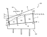
本実施形態のスクリュ式押出機101は、ケーシング下流部14の断面図である図8に示すように、投入口11の下流側端11aとフライト部7の下流側端との中間部におけるクリアランスD3が、フライト部7の下流側端におけるクリアランスD1よりも小さくされている。
本実施形態のスクリュ式押出機101は、ケーシング下流部14の断面図である図8に示すように、投入口11の下流側端11aとフライト部7の下流側端との中間部におけるクリアランスD3が、フライト部7の下流側端におけるクリアランスD1よりも小さくされている。
本実施形態のスクリュ式押出機101では、軸部6の径方向の断面視において、投入口11の下流側端11aからフライト部7の下流側端にわたって、フライト部7の頂点を結ぶ仮想線(破線)が曲線であり、ケーシング4の内壁面(実線)が直線である。これにより、投入口11の下流側端11aからフライト部7の下流側端にわたって、クリアランスが連続的に変化している。本実施形態では、フライト部7の頂点を結ぶ仮想線は二次曲線であるが、曲線はこれに限定されない。また、ケーシング4の内壁面(実線)が曲線であってもよい。
図4の座標を用いて、本実施形態のスクリュ形状におけるスクリュ軸方向のクリアランスと粘度との関係を図9に示す。ケーシング4の下流側端(原点0)から中間部に向かうにつれて、クリアランスδは小さくなり、中間部から投入口11の下流側端11aに向かうにつれて、クリアランスδは大きくなる。そのため、ケーシング4の下流側端(原点0)から中間部に向かうにつれて、材料の粘度μは大きくなり、中間部から投入口11の下流側端11aに向かうにつれて、材料の粘度μは小さくなる。
図8に示すように、中間部におけるクリアランスD3を、フライト部7の下流側端におけるクリアランスD1よりも小さくすることで、第1実施形態のスクリュ式押出機1に比べて、中間部におけるひずみ速度が小さくなる。その結果、中間部において、第1実施形態のスクリュ式押出機1に比べて材料の粘度が高めに維持されるので、中間部から上流側への材料漏れが抑制され、搬送効率がさらに向上する。これにより、バンク部10での昇圧能力をさらに向上させることができる。
また、図6に示すように、第1実施形態のスクリュ式押出機1では、投入口11の下流側端11aにおけるクリアランスD2を大きくするために、投入口11の下流側端11aにおけるフライト部7の高さを低くする必要がある。そのため、クリアランスが一定の場合に比べて、ピッチごとの体積V1~V3が小さくなり、搬送能力が低下する。
そこで、本実施形態では、図8に示すように、軸部6の径方向の断面視において、投入口11の下流側端11aからフライト部7の下流側端にわたって、フライト部7の頂点を結ぶ仮想線を曲線にする。これにより、中間部におけるフライト部7の高さが高く維持される。その結果、第1実施形態のスクリュ式押出機1に比べて、ピッチごとの体積V1~V3が大きくなる。すなわち、第1実施形態のV1よりも本実施形態のV1が大きく、第1実施形態のV2よりも本実施形態のV2が大きく、第1実施形態のV3よりも本実施形態のV3が大きい。そのため、搬送能力を向上させることができる。
ここで、図8において、スクリュ2,3のフライト部7における下流側端の頂部の底辺の中心を原点0とし、スクリュ2,3の軸部6の表面に沿ってx座標をとり、軸部6の表面に垂直な方向にy座標をとる。フライト部7の下流側端の頂部のx座標を0、フライト部7の下流側端の頂部から1回転分上流側の頂部のx座標をX1、フライト部7の下流側端の頂部から2回転分上流側の頂部のx座標をX2、フライト部7の下流側端の頂部から3回転分上流側の頂部のx座標をX3とする。また、フライト部7の下流側端の頂部の高さをY0、フライト部7の下流側端の頂部から1回転分上流側の頂部の高さをY1、フライト部7の下流側端の頂部から2回転分上流側の頂部の高さをY2、フライト部7の下流側端の頂部から3回転分上流側の頂部の高さをY3とする。
フライト部7の下流側端の頂部の頂点と、フライト部7の下流側端の頂部から3回転分上流側の頂部の頂点とを結ぶ直線(一点鎖線)は、y=(Y3-Y0)/X3+Y0で表せる。フライト部7の下流側端の頂部の頂点と、フライト部7の下流側端の頂部から3回転分上流側の頂部の頂点とを結ぶ二次曲線(点線)は、y=ax2+bx+cで表せる。この二次曲線におけるフライト部7の下流側端での傾きはb、フライト部7の下流側端の頂部から3回転分上流側の頂部での傾きは2aX3+bである。
二次曲線の傾きは、フライト部7の下流側端で、直線の傾き(Y3-Y0)/X3より大きく、フライト部7の下流側端の頂部から3回転分上流側の頂部で、直線の傾き(Y3-Y0)/X3より小さい。よって、b>(Y3-Y0)/X3>2aX3+bの関係が成り立つ。
スクリュの形状因子を元に昇圧能力を簡易計算した結果を図10に示す。ここで、フライト高さの傾きは、スクリュ2,3の軸方向に沿ってフライト部7の頂点を結んだ直線の傾きを指している。従来のスクリュ形状では、フライト高さの傾き比は1.0であり、投入口11の下流側端11aにおけるクリアランスD2を、フライト部7の下流側端におけるクリアランスD1よりも大きくするほど、フライト高さの傾き比の値は小さくなる。
従来のスクリュ形状では、フライト高さの傾きと、圧力比および搬送能力比とは概ね比例関係となっており、圧力比と搬送能力比とは、トレードオフの関係となっている。一方、本実施形態のスクリュ形状では、搬送能力が従来並みに維持された状態で、圧力比は約7倍程度となっている。このことから、バンク部10での昇圧能力を向上させながら、搬送能力が従来並みまで向上していることがわかる。
(効果)
以上に述べたように、本実施形態に係るスクリュ式押出機101によると、投入口11の下流側端11aとフライト部7の下流側端との中間部におけるクリアランスD3が、フライト部7の下流側端におけるクリアランスD1よりも小さくされている。これにより、第1実施形態のスクリュ式押出機1に比べて、中間部におけるひずみ速度が小さくなる。その結果、中間部において、第1実施形態のスクリュ式押出機1に比べて材料の粘度が高めに維持されるので、中間部から上流側への材料漏れが抑制され、搬送効率がさらに向上する。これにより、バンク部での昇圧能力をさらに向上させることができる。
以上に述べたように、本実施形態に係るスクリュ式押出機101によると、投入口11の下流側端11aとフライト部7の下流側端との中間部におけるクリアランスD3が、フライト部7の下流側端におけるクリアランスD1よりも小さくされている。これにより、第1実施形態のスクリュ式押出機1に比べて、中間部におけるひずみ速度が小さくなる。その結果、中間部において、第1実施形態のスクリュ式押出機1に比べて材料の粘度が高めに維持されるので、中間部から上流側への材料漏れが抑制され、搬送効率がさらに向上する。これにより、バンク部での昇圧能力をさらに向上させることができる。
また、投入口11の下流側端11aからフライト部7の下流側端にわたって、クリアランスが連続的に変化している。これにより、クリアランスが不連続の場合に比べて、バンク部10での昇圧能力をさらに向上させることができる。
また、軸部6の径方向の断面視において、投入口11の下流側端11aからフライト部7の下流側端にわたって、フライト部7の頂点を結ぶ仮想線が曲線である。第1実施形態のスクリュ式押出機1では、クリアランスが一定の場合に比べて、スクリュのピッチごとの体積V1~V3が小さくなり、搬送能力が低下する。そこで、軸部6の径方向の断面視において、投入口11の下流側端11aからフライト部7の下流側端にわたって、フライト部7の頂点を結ぶ仮想線を曲線にする。これにより、中間部におけるフライト部7の高さが高く維持される。その結果、第1実施形態のスクリュ式押出機1に比べて、ピッチごとの体積V1~V3が大きくなるので、搬送能力を向上させることができる。
また、軸部6の径方向の断面視において、投入口11の下流側端11aからフライト部7の下流側端にわたって、ケーシング4の内壁面が直線である。これにより、ケーシング4を作成しやすい。
(変形例)
なお、本実施形態のスクリュ式押出機101においては、ケーシング下流部14の断面図である図11に示すように、軸部6の径方向の断面視において、投入口11の下流側端11aからフライト部7の下流側端にわたって、フライト部7の頂点を結ぶ仮想線(破線)が直線であり、ケーシング4の内壁面(実線)が曲線であってもよい。このような構成であっても、投入口11の下流側端11aからフライト部7の下流側端にわたって、クリアランスが連続的に変化する。本変形例では、ケーシング4の内壁面が二次曲線であるが、曲線はこれに限定されない。また、フライト部7の頂点を結ぶ仮想線(破線)が曲線であってもよい。
なお、本実施形態のスクリュ式押出機101においては、ケーシング下流部14の断面図である図11に示すように、軸部6の径方向の断面視において、投入口11の下流側端11aからフライト部7の下流側端にわたって、フライト部7の頂点を結ぶ仮想線(破線)が直線であり、ケーシング4の内壁面(実線)が曲線であってもよい。このような構成であっても、投入口11の下流側端11aからフライト部7の下流側端にわたって、クリアランスが連続的に変化する。本変形例では、ケーシング4の内壁面が二次曲線であるが、曲線はこれに限定されない。また、フライト部7の頂点を結ぶ仮想線(破線)が曲線であってもよい。
図8に示すように、フライト部7の頂点を結ぶ仮想線(破線)が曲線であると、スクリュ2,3の軸部6同士の間隔によっては、対となるスクリュと干渉する可能性がある。しかし、図11に示すように、ケーシング4の内壁面(実線)を曲線にすれば、フライト部7の頂点を結ぶ仮想線を曲線にする場合に比べて、軸部6同士の間隔を狭くすることができる。
図11において、スクリュ2,3のフライト部7における下流側端の頂部の底辺の中心を原点0とし、スクリュ2,3の軸部6の表面に沿ってx座標をとり、軸部6の表面に垂直な方向にy座標をとる。フライト部7の下流側端の頂部のx座標を0、フライト部7の下流側端の頂部から1回転分上流側の頂部のx座標をX1、フライト部7の下流側端の頂部から2回転分上流側の頂部のx座標をX2、フライト部7の下流側端の頂部から3回転分上流側の頂部のx座標をX3とする。また、フライト部7の下流側端の頂部の高さをY0、フライト部7の下流側端の頂部から1回転分上流側の頂部の高さをY1、フライト部7の下流側端の頂部から2回転分上流側の頂部の高さをY2、フライト部7の下流側端の頂部から3回転分上流側の頂部の高さをY3とする。
フライト部7の下流側端の頂部の頂点と、フライト部7の下流側端の頂部から3回転分上流側の頂部の頂点とを結ぶ直線(点線)は、y=(Y3-Y0)/X3+Y0で表せる。ケーシングの内壁面の二次曲線は、y=ax2+bx+YWで表せる。ここで、YWは、この二次曲線とy軸との交点である。この二次曲線におけるフライト部7の下流側端での傾きはb、フライト部7の下流側端の頂部から3回転分上流側の頂部での傾きは2aX3+bである。
二次曲線の傾きは、フライト部7の下流側端で、直線の傾き(Y3-Y0)/X3より小さく、フライト部7の下流側端の頂部から3回転分上流側の頂部で、直線の傾き(Y3-Y0)/X3より大きい。よって、b<(Y3-Y0)/X3<2aX3+bの関係が成り立つ。
(効果)
以上に述べたように、本変形例によると、軸部6の径方向の断面視において、投入口11の下流側端11aからフライト部7の下流側端にわたって、ケーシング4の内壁面が曲線である。フライト部7の頂点を結ぶ仮想線(破線)が曲線であると、スクリュ2,3の軸部6同士の間隔によっては、対となるスクリュと干渉する可能性がある。これに対して、ケーシング4の内壁面(実線)を曲線にすることで、フライト部7の頂点を結ぶ仮想線を曲線にする場合に比べて、軸部6同士の間隔を狭くすることができる。
以上に述べたように、本変形例によると、軸部6の径方向の断面視において、投入口11の下流側端11aからフライト部7の下流側端にわたって、ケーシング4の内壁面が曲線である。フライト部7の頂点を結ぶ仮想線(破線)が曲線であると、スクリュ2,3の軸部6同士の間隔によっては、対となるスクリュと干渉する可能性がある。これに対して、ケーシング4の内壁面(実線)を曲線にすることで、フライト部7の頂点を結ぶ仮想線を曲線にする場合に比べて、軸部6同士の間隔を狭くすることができる。
また、軸部6の径方向の断面視において、投入口11の下流側端11aからフライト部7の下流側端にわたって、フライト部7の頂点を結ぶ仮想線が直線である。これにより、スクリュ2,3を作成しやすい。
[第3実施形態]
次に、第3実施形態のスクリュ式押出機について、図面を参照しつつ説明する。なお、第1実施形態と共通する構成およびそれにより奏される効果については説明を省略し、主に、第1実施形態と異なる点について説明する。なお、第1実施形態と同じ部材については、第1実施形態と同じ符号を付している。
次に、第3実施形態のスクリュ式押出機について、図面を参照しつつ説明する。なお、第1実施形態と共通する構成およびそれにより奏される効果については説明を省略し、主に、第1実施形態と異なる点について説明する。なお、第1実施形態と同じ部材については、第1実施形態と同じ符号を付している。
(スクリュ式押出機の構成)
本実施形態のスクリュ式押出機201は、ケーシング下流部14の断面図である図12に示すように、フライト部7の下流側端におけるクリアランスD1が、フライト部7における下流側端の頂部から1回転分上流側の頂部におけるクリアランスD4よりも小さくされている。なお、クリアランスD1が、クリアランスD4と同じであってもよい。クリアランスD1は、クリアランスD3よりも大きい。
本実施形態のスクリュ式押出機201は、ケーシング下流部14の断面図である図12に示すように、フライト部7の下流側端におけるクリアランスD1が、フライト部7における下流側端の頂部から1回転分上流側の頂部におけるクリアランスD4よりも小さくされている。なお、クリアランスD1が、クリアランスD4と同じであってもよい。クリアランスD1は、クリアランスD3よりも大きい。
本実施形態のスクリュ式押出機101では、軸部6の径方向の断面視において、ケーシング4の内壁面(実線)が直線である。また、フライト部7における下流側端の頂部から1回転分上流側の頂部を起点とし、その頂部を通り、投入口11の下流側端11aにわたって、フライト部7の頂点を結ぶ仮想線(破線)が曲線であり、さらに、上記した1回転分上流側の頂部から下流側端の頂部にわたって、フライト部7の頂点を結ぶ仮想線(破線)が別の曲線である。これにより、投入口11の下流側端11aからフライト部7の下流側端にわたって、クリアランスが連続的に変化している。本実施形態では、2つの仮想線はそれぞれ二次曲線であるが、曲線はこれに限定されない。また、ケーシング4の内壁面(実線)が曲線であってもよい。
フライト部7の下流側端におけるクリアランスD1を、フライト部7における下流側端の頂部から1回転分上流側の頂部におけるクリアランスD4よりも小さくすることで、第2実施形態のスクリュ式押出機101に比べて、フライト部7の下流側端におけるひずみ速度が小さくなる。その結果、フライト部7の下流側端において、第2実施形態のスクリュ式押出機101に比べて材料の粘度が高めに維持されるので、バンク部10からの材料漏れが抑制され、搬送効率がさらに向上する。これにより、バンク部10での昇圧能力をさらに向上させることができる。
また、図8に示すように、第2実施形態のスクリュ式押出機101では、フライト部7の下流側端における頂部の高さが低くなり、フライト部7の下流側における体積V1が小さくなる傾向にある。そこで、本実施形態では、図12に示すように、軸部6の径方向の断面視において、1回転分上流側の頂部から下流側端の頂部にわたって、フライト部7の頂点を結ぶ仮想線を曲線にする。これにより、第2実施形態のスクリュ式押出機101に比べて、フライト部7の下流側端における頂部の高さが高くなるので、フライト部7の下流側における搬送量(体積V1)を増加させることができる。
また、スクリュ式押出機201の生産能力は、ローラ8,9(図1参照)の回転数で概ね決定される。そのため、実機運転ではローラ8,9の回転数を指定し、バンク部10の圧力が一定となるようにスクリュ2,3の回転数を制御する。よって、フライト部7の高さに依存するスクリュ2,3の搬送能力が低いと、スクリュ2,3の回転数が増加することとなる。よって、フライト部7の下流側における体積(搬送量)V1を大きくすることで、スクリュ2,3の回転数を抑えることができる。
第1~3実施形態における昇圧能力の解析結果を図13に示す。図13から、第2実施形態のスクリュ式押出機101の方が、第1実施形態のスクリュ式押出機1よりも昇圧能力が高く、第3実施形態のスクリュ式押出機201が最も昇圧能力が高いことがわかる。これは、第3実施形態のスクリュ式押出機201において、第2実施形態のスクリュ式押出機101よりも搬送能力が改善されたことと、フライト部7の下流側端におけるクリアランスD1を第2実施形態のスクリュ式押出機101よりも小さくしたことで、フライト部7の下流側端におけるひずみ速度が小さくなり、材料の粘度の低下が抑えられたことで、バンク部10からの材料漏れが抑えられ、昇圧能力が改善したためである。
図12において、スクリュ2,3のフライト部7における下流側端の頂部の底辺の中心を原点0とし、スクリュ2,3の軸部6の表面に沿ってx座標をとり、軸部6の表面に垂直な方向にy座標をとる。フライト部7の下流側端の頂部のx座標を0、フライト部7の下流側端の頂部から1回転分上流側の頂部のx座標をX1、フライト部7の下流側端の頂部から2回転分上流側の頂部のx座標をX2、フライト部7の下流側端の頂部から3回転分上流側の頂部のx座標をX3とする。また、フライト部7の下流側端の頂部の高さをY0’、フライト部7の下流側端の頂部から1回転分上流側の頂部の高さをY1、フライト部7の下流側端の頂部から2回転分上流側の頂部の高さをY2、フライト部7の下流側端の頂部から3回転分上流側の頂部の高さをY3とする。また、図8と同じ二次曲線のy軸との交点をY0とする。
交点Y0と、フライト部7の下流側端の頂部から3回転分上流側の頂部の頂点とを結ぶ直線(一点鎖線)は、y=(Y3-Y0)/X3+Y0で表せる。交点Y0と、フライト部7の下流側端の頂部から3つ上流側の頂部の頂点とを結ぶ二次曲線(点線)は、y=ax2+bx+Y0で表せる。この二次曲線におけるフライト部7の下流側端での傾きはb、フライト部7の下流側端の頂部から3回転分上流側の頂部での傾きは2aX3+bである。
二次曲線の傾きは、フライト部7の下流側端で、直線の傾き(Y3-Y0)/X3より大きく、フライト部7の下流側端の頂部から3回転分上流側の頂部で、直線の傾き(Y3-Y0)/X3より小さい。よって、b>(Y3-Y0)/X3>2aX3+bの関係が成り立つ。
また、フライト部7の下流側端の頂部の頂点と、フライト部7の下流側端の頂部から1回転分上流側の頂部の頂点とを結ぶ二次曲線(点線)は、y=cx2+dx+Y0’で表せる。この二次曲線におけるフライト部7の下流側端での傾きはd、フライト部7の下流側端の頂部から1回転分上流側の頂部での傾きは2cX1+dである。
二次曲線の傾きは、フライト部7の下流側端で、直線の傾き(Y3-Y0)/X3より小さく、フライト部7の下流側端の頂部から1回転分上流側の頂部で、二次曲線の傾き2aX1+bと同じである。よって、d<(Y3-Y0)/X3、2aX1+b=2cX1+dの関係が成り立つ。
(効果)
以上に述べたように、本実施形態に係るスクリュ式押出機201によると、フライト部7の下流側端におけるクリアランスD1が、フライト部7における下流側端の頂部から1回転分上流側の頂部におけるクリアランスD4と同じか、それよりも小さくされている。これにより、第2実施形態のスクリュ式押出機101に比べて、フライト部7の下流側端におけるひずみ速度が小さくなる。その結果、フライト部7の下流側端において、第2実施形態のスクリュ式押出機101に比べて材料の粘度が高めに維持されるので、バンク部10からの材料漏れが抑制され、搬送効率がさらに向上する。これにより、バンク部10での昇圧能力をさらに向上させることができる。
以上に述べたように、本実施形態に係るスクリュ式押出機201によると、フライト部7の下流側端におけるクリアランスD1が、フライト部7における下流側端の頂部から1回転分上流側の頂部におけるクリアランスD4と同じか、それよりも小さくされている。これにより、第2実施形態のスクリュ式押出機101に比べて、フライト部7の下流側端におけるひずみ速度が小さくなる。その結果、フライト部7の下流側端において、第2実施形態のスクリュ式押出機101に比べて材料の粘度が高めに維持されるので、バンク部10からの材料漏れが抑制され、搬送効率がさらに向上する。これにより、バンク部10での昇圧能力をさらに向上させることができる。
また、1回転分上流側の頂部から下流側端の頂部にわたって、クリアランスが連続的に変化している。これにより、クリアランスが不連続の場合に比べて、バンク部10での昇圧能力をさらに向上させることができる。
また、軸部6の径方向の断面視において、1回転分上流側の頂部から下流側端の頂部にわたって、フライト部7の頂点を結ぶ仮想線が曲線である。第2実施形態のスクリュ式押出機101では、フライト部7の下流側端における頂部の高さが低くなり、フライト部7の下流側における体積V1が小さくなる傾向にある。そこで、軸部6の径方向の断面視において、1回転分上流側の頂部から下流側端の頂部にわたって、フライト部7の頂点を結ぶ仮想線を曲線にする。これにより、第2実施形態のスクリュ式押出機101に比べて、フライト部7の下流側端における頂部の高さが高くなるので、フライト部7の下流側における搬送量(体積V1)を増加させることができる。
また、軸部6の径方向の断面視において、1回転分上流側の頂部から下流側端の頂部にわたって、ケーシング4の内壁面が直線である。これにより、ケーシング4を作成しやすい。
(変形例)
なお、本実施形態のスクリュ式押出機201においては、ケーシング下流部14の断面図である図14に示すように、軸部6の径方向の断面視において、投入口11の下流側端11aからフライト部7の下流側端にわたって、フライト部7の頂点を結ぶ仮想線(破線)は直線である。また、フライト部7における下流側端の頂部から1回転分上流側の頂部から、投入口11の下流側端11aにわたって、ケーシング4の内壁面(実線)は曲線である。この構成で、フライト部7における1回転分上流側の頂部から下流側端の頂部にわたって、ケーシング4の内壁面(実線)を別の曲線としてもよい。このような構成であっても、投入口11の下流側端11aからフライト部7の下流側端にわたって、クリアランスが連続的に変化している。本変形例では、2つの仮想線はそれぞれ二次曲線であるが、曲線はこれに限定されない。また、フライト部7の頂点を結ぶ仮想線(破線)が曲線であってもよい。
なお、本実施形態のスクリュ式押出機201においては、ケーシング下流部14の断面図である図14に示すように、軸部6の径方向の断面視において、投入口11の下流側端11aからフライト部7の下流側端にわたって、フライト部7の頂点を結ぶ仮想線(破線)は直線である。また、フライト部7における下流側端の頂部から1回転分上流側の頂部から、投入口11の下流側端11aにわたって、ケーシング4の内壁面(実線)は曲線である。この構成で、フライト部7における1回転分上流側の頂部から下流側端の頂部にわたって、ケーシング4の内壁面(実線)を別の曲線としてもよい。このような構成であっても、投入口11の下流側端11aからフライト部7の下流側端にわたって、クリアランスが連続的に変化している。本変形例では、2つの仮想線はそれぞれ二次曲線であるが、曲線はこれに限定されない。また、フライト部7の頂点を結ぶ仮想線(破線)が曲線であってもよい。
このような構成であっても、バンク部10からの材料漏れが抑制され、搬送効率がさらに向上するので、バンク部10での昇圧能力をさらに向上させることができる。
図14において、スクリュ2,3のフライト部7における下流側端の頂部の底辺の中心を原点0とし、スクリュ2,3の軸部6の表面に沿ってx座標をとり、軸部6の表面に垂直な方向にy座標をとる。フライト部7の下流側端の頂部のx座標を0、フライト部7の下流側端の頂部から1回転分上流側の頂部のx座標をX1、フライト部7の下流側端の頂部から2回転分上流側の頂部のx座標をX2、フライト部7の下流側端の頂部から3回転分上流側の頂部のx座標をX3とする。また、フライト部7の下流側端の頂部の高さをY0、フライト部7の下流側端の頂部から1回転分上流側の頂部の高さをY1、フライト部7の下流側端の頂部から2回転分上流側の頂部の高さをY2、フライト部7の下流側端の頂部から3回転分上流側の頂部の高さをY3とする。
フライト部7の下流側端の頂部の頂点と、フライト部7の下流側端の頂部から3回転分上流側の頂部の頂点とを結ぶ直線(点線)は、y=(Y3-Y0)/X3+Y0で表せる。また、図11と同様のケーシングの内壁面の二次曲線は、y=ax2+bx+YWで表せる。ここで、YWは、この二次曲線とy軸との交点である。この二次曲線におけるフライト部7の下流側端での傾きはb、フライト部7の下流側端の頂部から3回転分上流側の頂部での傾きは2aX3+bである。
二次曲線の傾きは、フライト部7の下流側端で、直線の傾き(Y3-Y0)/X3より小さく、フライト部7の下流側端の頂部から3回転分上流側の頂部で、直線の傾き(Y3-Y0)/X3より大きい。よって、b<(Y3-Y0)/X3<2aX3+bの関係が成り立つ。
また、フライト部7の下流側端の頂部から、フライト部7の下流側端の頂部から1回転分上流側の頂部にかけてのケーシングの内壁面の二次曲線(実線)は、y=cx2+dx+Y0’で表せる。ここで、Y0’は、この二次曲線とy軸との交点である。この二次曲線におけるフライト部7の下流側端での傾きはd、フライト部7の下流側端の頂部から1回転分上流側の頂部での傾きは2cX1+dである。
二次曲線の傾きは、フライト部7の下流側端で、直線の傾き(Y3-Y0)/X3より大きく、フライト部7の下流側端の頂部から1回転分上流側の頂部で、二次曲線の傾き2aX1+bと同じである。よって、d>(Y3-Y0)/X3、2aX1+b=2cX1+dの関係が成り立つ。
(効果)
以上に述べたように、本変形例によると、軸部6の径方向の断面視において、1回転分上流側の頂部から下流側端の頂部にわたって、フライト部7の頂点を結ぶ仮想線が直線である。これにより、スクリュ2,3を作成しやすい。
以上に述べたように、本変形例によると、軸部6の径方向の断面視において、1回転分上流側の頂部から下流側端の頂部にわたって、フライト部7の頂点を結ぶ仮想線が直線である。これにより、スクリュ2,3を作成しやすい。
以上、本発明の実施形態を説明したが、具体例を例示したに過ぎず、特に本発明を限定するものではなく、具体的構成などは、適宜設計変更可能である。また、発明の実施の形態に記載された、作用及び効果は、本発明から生じる最も好適な作用及び効果を列挙したに過ぎず、本発明による作用及び効果は、本発明の実施の形態に記載されたものに限定されるものではない。
本出願は、2018年6月25日出願の日本特許出願(特願2018-119855)に基づくものであり、その内容は本出願の中に参照として援用される。
1,101,201 スクリュ式押出機
2,3 スクリュ
4 ケーシング
6 軸部
7 フライト部
8,9 ローラ
10 バンク部
11 投入口
11a 下流側端
13 ケーシング上流部
14 ケーシング下流部
50 シート
2,3 スクリュ
4 ケーシング
6 軸部
7 フライト部
8,9 ローラ
10 バンク部
11 投入口
11a 下流側端
13 ケーシング上流部
14 ケーシング下流部
50 シート
Claims (16)
- 一対のスクリュと、
前記一対のスクリュを収容し、上流側に材料の投入口が設けられたケーシングと、
前記ケーシングの下流側に前記材料をシート状に押出成形するローラダイと、
を備え、混練物の押し出しを行うスクリュ式押出機において、
前記スクリュは、軸部と、前記軸部の外周面に設けられた螺旋状のフライト部と、を有しており、
前記フライト部は、前記軸部の表面から前記フライト部の先端までの径方向距離が混練物の押出方向の下流側端に向かって漸減する形状にされており、
前記ケーシングは先細りの形状を有し、
前記投入口の下流側端から前記フライト部の下流側端にかけての範囲において、前記投入口の下流側端における、前記フライト部の頂部と前記ケーシングの内壁面との間のクリアランスが、他の部分における前記クリアランスよりも大きくされているスクリュ式押出機。 - 前記フライト部の下流側端から前記投入口の下流側端にわたって、前記クリアランスが漸増している請求項1に記載のスクリュ式押出機。
- 前記投入口の下流側端と前記フライト部の下流側端との中間部における前記クリアランスが、前記フライト部の下流側端における前記クリアランスよりも小さくされている請求項1に記載のスクリュ式押出機。
- 前記投入口の下流側端から前記フライト部の下流側端にわたって、前記クリアランスが連続的に変化している請求項3に記載のスクリュ式押出機。
- 前記軸部の径方向の断面視において、前記投入口の下流側端から前記フライト部の下流側端にわたって、前記フライト部の頂点を結ぶ仮想線が曲線である請求項4に記載のスクリュ式押出機。
- 前記軸部の径方向の断面視において、前記投入口の下流側端から前記フライト部の下流側端にわたって、前記ケーシングの内壁面が直線である請求項5に記載のスクリュ式押出機。
- 前記軸部の径方向の断面視において、前記投入口の下流側端から前記フライト部の下流側端にわたって、前記ケーシングの内壁面が曲線である請求項4に記載のスクリュ式押出機。
- 前記軸部の径方向の断面視において、前記投入口の下流側端から前記フライト部の下流側端にわたって、前記フライト部の頂点を結ぶ仮想線が直線である請求項7に記載のスクリュ式押出機。
- 前記フライト部の下流側端における前記クリアランスが、前記フライト部における下流側端の前記頂部から1回転分上流側の前記頂部における前記クリアランスと同じか、それよりも小さくされている請求項3~6のいずれか1項に記載のスクリュ式押出機。
- 前記1回転分上流側の前記頂部から下流側端の前記頂部にわたって、前記クリアランスが連続的に変化している請求項9に記載のスクリュ式押出機。
- 前記軸部の径方向の断面視において、前記1回転分上流側の前記頂部から下流側端の前記頂部にわたって、前記フライト部の頂点を結ぶ仮想線が曲線である請求項10に記載のスクリュ式押出機。
- 前記軸部の径方向の断面視において、前記1回転分上流側の前記頂部から下流側端の前記頂部にわたって、前記ケーシングの内壁面が直線である請求項11に記載のスクリュ式押出機。
- 前記フライト部の下流側端における前記クリアランスが、前記フライト部における下流側端の前記頂部から1回転分上流側の前記頂部における前記クリアランスと同じか、それよりも小さくされている請求項3又は4又は7又は8のいずれか1項に記載のスクリュ式押出機。
- 前記1回転分上流側の前記頂部から下流側端の前記頂部にわたって、前記クリアランスが連続的に変化している請求項13に記載のスクリュ式押出機。
- 前記軸部の径方向の断面視において、前記1回転分上流側の前記頂部から下流側端の前記頂部にわたって、前記ケーシングの内壁面が曲線である請求項14に記載のスクリュ式押出機。
- 前記軸部の径方向の断面視において、前記1回転分上流側の前記頂部から下流側端の前記頂部にわたって、前記フライト部の頂点を結ぶ仮想線が直線である請求項15に記載のスクリュ式押出機。
Priority Applications (4)
| Application Number | Priority Date | Filing Date | Title |
|---|---|---|---|
| US17/252,397 US20210187814A1 (en) | 2018-06-25 | 2019-05-31 | Screw-type extruder |
| EP19826684.3A EP3797967A4 (en) | 2018-06-25 | 2019-05-31 | SCREW EXTRUDER |
| KR1020207036933A KR20210014134A (ko) | 2018-06-25 | 2019-05-31 | 스크루식 압출기 |
| CN201980042677.2A CN112292249A (zh) | 2018-06-25 | 2019-05-31 | 螺杆式挤出机 |
Applications Claiming Priority (2)
| Application Number | Priority Date | Filing Date | Title |
|---|---|---|---|
| JP2018-119855 | 2018-06-25 | ||
| JP2018119855A JP2020001176A (ja) | 2018-06-25 | 2018-06-25 | スクリュ式押出機 |
Publications (1)
| Publication Number | Publication Date |
|---|---|
| WO2020003898A1 true WO2020003898A1 (ja) | 2020-01-02 |
Family
ID=68987069
Family Applications (1)
| Application Number | Title | Priority Date | Filing Date |
|---|---|---|---|
| PCT/JP2019/021875 Ceased WO2020003898A1 (ja) | 2018-06-25 | 2019-05-31 | スクリュ式押出機 |
Country Status (7)
| Country | Link |
|---|---|
| US (1) | US20210187814A1 (ja) |
| EP (1) | EP3797967A4 (ja) |
| JP (1) | JP2020001176A (ja) |
| KR (1) | KR20210014134A (ja) |
| CN (1) | CN112292249A (ja) |
| TW (1) | TW202000422A (ja) |
| WO (1) | WO2020003898A1 (ja) |
Families Citing this family (1)
| Publication number | Priority date | Publication date | Assignee | Title |
|---|---|---|---|---|
| EP4039434B1 (de) * | 2021-02-04 | 2024-04-03 | Coperion GmbH | Beschickungs-schneckenmaschine zum beschicken einer aufbereitungs-schneckenmaschine, und darauf bezogenes verfahren |
Citations (5)
| Publication number | Priority date | Publication date | Assignee | Title |
|---|---|---|---|---|
| JPS622624B2 (ja) | 1984-02-20 | 1987-01-21 | Shinko Elec Ind | |
| JPH07308952A (ja) * | 1994-05-19 | 1995-11-28 | Mitsubishi Chem Corp | 多孔性樹脂成型体の製造方法 |
| JP2000317291A (ja) | 1999-05-06 | 2000-11-21 | Nippon Spindle Mfg Co Ltd | 混練物移送装置 |
| JP2006341478A (ja) * | 2005-06-09 | 2006-12-21 | Mitsubishi Heavy Ind Ltd | 連続混練装置及び該装置を有する混練システム |
| JP2018119855A (ja) | 2017-01-25 | 2018-08-02 | 株式会社ナガセインテグレックス | 起立面測定装置及び起立面測定方法 |
Family Cites Families (13)
| Publication number | Priority date | Publication date | Assignee | Title |
|---|---|---|---|---|
| JPH05104607A (ja) * | 1991-10-21 | 1993-04-27 | Kobe Steel Ltd | ローラダイ付押出機 |
| JPH0664020A (ja) * | 1992-08-21 | 1994-03-08 | Masao Moriyama | 樹脂材料をシート状に成形する装置 |
| JPH06114913A (ja) * | 1992-10-06 | 1994-04-26 | Kobe Steel Ltd | ローラダイ付き押出機 |
| US5312224A (en) * | 1993-03-12 | 1994-05-17 | International Business Machines Corporation | Conical logarithmic spiral viscosity pump |
| US6609819B2 (en) * | 2001-07-24 | 2003-08-26 | Wenger Mfg | Twin screw extruder with conical non-parallel converging screws |
| JP4064308B2 (ja) * | 2002-07-17 | 2008-03-19 | 鈴鹿エンヂニヤリング株式会社 | ゴム練り機 |
| CN201151183Y (zh) * | 2007-10-12 | 2008-11-19 | 佛山市顺德区震德塑料机械有限公司 | 螺旋芯棒式螺杆混炼头 |
| JP5027717B2 (ja) * | 2008-04-08 | 2012-09-19 | 株式会社モリヤマ | 2軸押出機 |
| JP5984186B2 (ja) * | 2013-03-07 | 2016-09-06 | 日本スピンドル製造株式会社 | 2軸押出機 |
| JP5571221B1 (ja) * | 2013-04-09 | 2014-08-13 | 東洋ゴム工業株式会社 | ローラヘッド押出機およびその制御方法 |
| JP2015196355A (ja) * | 2014-04-02 | 2015-11-09 | 日立金属株式会社 | ブレーカープレートおよび押出機 |
| CN104647721B (zh) * | 2015-01-14 | 2017-10-27 | 李建钢 | 一种挤出装置 |
| JP6662747B2 (ja) * | 2016-10-07 | 2020-03-11 | 株式会社神戸製鋼所 | スクリュ式押出機 |
-
2018
- 2018-06-25 JP JP2018119855A patent/JP2020001176A/ja active Pending
-
2019
- 2019-05-31 EP EP19826684.3A patent/EP3797967A4/en not_active Withdrawn
- 2019-05-31 KR KR1020207036933A patent/KR20210014134A/ko not_active Ceased
- 2019-05-31 US US17/252,397 patent/US20210187814A1/en not_active Abandoned
- 2019-05-31 CN CN201980042677.2A patent/CN112292249A/zh active Pending
- 2019-05-31 WO PCT/JP2019/021875 patent/WO2020003898A1/ja not_active Ceased
- 2019-06-20 TW TW108121480A patent/TW202000422A/zh unknown
Patent Citations (5)
| Publication number | Priority date | Publication date | Assignee | Title |
|---|---|---|---|---|
| JPS622624B2 (ja) | 1984-02-20 | 1987-01-21 | Shinko Elec Ind | |
| JPH07308952A (ja) * | 1994-05-19 | 1995-11-28 | Mitsubishi Chem Corp | 多孔性樹脂成型体の製造方法 |
| JP2000317291A (ja) | 1999-05-06 | 2000-11-21 | Nippon Spindle Mfg Co Ltd | 混練物移送装置 |
| JP2006341478A (ja) * | 2005-06-09 | 2006-12-21 | Mitsubishi Heavy Ind Ltd | 連続混練装置及び該装置を有する混練システム |
| JP2018119855A (ja) | 2017-01-25 | 2018-08-02 | 株式会社ナガセインテグレックス | 起立面測定装置及び起立面測定方法 |
Non-Patent Citations (1)
| Title |
|---|
| See also references of EP3797967A4 * |
Also Published As
| Publication number | Publication date |
|---|---|
| EP3797967A1 (en) | 2021-03-31 |
| CN112292249A (zh) | 2021-01-29 |
| KR20210014134A (ko) | 2021-02-08 |
| US20210187814A1 (en) | 2021-06-24 |
| EP3797967A4 (en) | 2021-08-04 |
| JP2020001176A (ja) | 2020-01-09 |
| TW202000422A (zh) | 2020-01-01 |
Similar Documents
| Publication | Publication Date | Title |
|---|---|---|
| JP4255873B2 (ja) | コニカル二軸押出機及び脱水装置 | |
| JP6814709B2 (ja) | ロール付スクリュ押出機 | |
| US20250367856A1 (en) | Extruder, dehydration cylinder, dehydrating method and manufacturing method of resin pellet | |
| WO2020003898A1 (ja) | スクリュ式押出機 | |
| CN118253222B (zh) | 异向差速螺杆捏合装置、连续捏合机、物料制作系统 | |
| JP2014172230A (ja) | 2軸押出機 | |
| CN106457644A (zh) | 双螺杆挤出机 | |
| CN109476043B (zh) | 捏合盘、螺杆元件和挤出机 | |
| WO2018142936A1 (ja) | スクリュ式押出機 | |
| TWI671178B (zh) | 螺旋式擠壓機 | |
| WO2019031351A1 (ja) | ロール付スクリュ押出機 | |
| TW202014292A (zh) | 擠出機 | |
| JP2000317291A (ja) | 混練物移送装置 | |
| JPH08258110A (ja) | 同方向回転噛み合い型二軸押出機 | |
| CN104159718A (zh) | 螺杆副和设有螺杆副的同向啮合双螺杆挤出机 | |
| CN119610605B (zh) | 一种橡胶冷喂料挤出机螺杆结构 | |
| CN222468674U (zh) | 螺杆机构的螺杆结构 | |
| JPH06270230A (ja) | 二軸押出機のスクリュー | |
| JPH06166086A (ja) | 2軸押出装置用スクリュー及び2軸押出装置 | |
| JPH06122120A (ja) | 原料の混練・混合方法及びスクリュシリンダ構造 |
Legal Events
| Date | Code | Title | Description |
|---|---|---|---|
| 121 | Ep: the epo has been informed by wipo that ep was designated in this application |
Ref document number: 19826684 Country of ref document: EP Kind code of ref document: A1 |
|
| ENP | Entry into the national phase |
Ref document number: 20207036933 Country of ref document: KR Kind code of ref document: A |
|
| NENP | Non-entry into the national phase |
Ref country code: DE |
|
| ENP | Entry into the national phase |
Ref document number: 2019826684 Country of ref document: EP Effective date: 20201223 |