WO2018221702A1 - 光触媒構造体、光触媒構造体組成物、光触媒被覆材、光触媒構造体の製造方法及びアルデヒド類の分解方法 - Google Patents
光触媒構造体、光触媒構造体組成物、光触媒被覆材、光触媒構造体の製造方法及びアルデヒド類の分解方法 Download PDFInfo
- Publication number
- WO2018221702A1 WO2018221702A1 PCT/JP2018/021090 JP2018021090W WO2018221702A1 WO 2018221702 A1 WO2018221702 A1 WO 2018221702A1 JP 2018021090 W JP2018021090 W JP 2018021090W WO 2018221702 A1 WO2018221702 A1 WO 2018221702A1
- Authority
- WO
- WIPO (PCT)
- Prior art keywords
- photocatalyst
- photocatalyst structure
- carrier
- metal
- structure according
- Prior art date
- Legal status (The legal status is an assumption and is not a legal conclusion. Google has not performed a legal analysis and makes no representation as to the accuracy of the status listed.)
- Ceased
Links
Images


Classifications
-
- B—PERFORMING OPERATIONS; TRANSPORTING
- B01—PHYSICAL OR CHEMICAL PROCESSES OR APPARATUS IN GENERAL
- B01J—CHEMICAL OR PHYSICAL PROCESSES, e.g. CATALYSIS OR COLLOID CHEMISTRY; THEIR RELEVANT APPARATUS
- B01J35/00—Catalysts, in general, characterised by their form or physical properties
- B01J35/30—Catalysts, in general, characterised by their form or physical properties characterised by their physical properties
- B01J35/39—Photocatalytic properties
-
- B—PERFORMING OPERATIONS; TRANSPORTING
- B01—PHYSICAL OR CHEMICAL PROCESSES OR APPARATUS IN GENERAL
- B01J—CHEMICAL OR PHYSICAL PROCESSES, e.g. CATALYSIS OR COLLOID CHEMISTRY; THEIR RELEVANT APPARATUS
- B01J29/00—Catalysts comprising molecular sieves
- B01J29/04—Catalysts comprising molecular sieves having base-exchange properties, e.g. crystalline zeolites
- B01J29/06—Crystalline aluminosilicate zeolites; Isomorphous compounds thereof
- B01J29/08—Crystalline aluminosilicate zeolites; Isomorphous compounds thereof of the faujasite type, e.g. type X or Y
- B01J29/085—Crystalline aluminosilicate zeolites; Isomorphous compounds thereof of the faujasite type, e.g. type X or Y containing rare earth elements, titanium, zirconium, hafnium, zinc, cadmium, mercury, gallium, indium, thallium, tin or lead
-
- A—HUMAN NECESSITIES
- A61—MEDICAL OR VETERINARY SCIENCE; HYGIENE
- A61L—METHODS OR APPARATUS FOR STERILISING MATERIALS OR OBJECTS IN GENERAL; DISINFECTION, STERILISATION OR DEODORISATION OF AIR; CHEMICAL ASPECTS OF BANDAGES, DRESSINGS, ABSORBENT PADS OR SURGICAL ARTICLES; MATERIALS FOR BANDAGES, DRESSINGS, ABSORBENT PADS OR SURGICAL ARTICLES
- A61L9/00—Disinfection, sterilisation or deodorisation of air
-
- B—PERFORMING OPERATIONS; TRANSPORTING
- B01—PHYSICAL OR CHEMICAL PROCESSES OR APPARATUS IN GENERAL
- B01D—SEPARATION
- B01D53/00—Separation of gases or vapours; Recovering vapours of volatile solvents from gases; Chemical or biological purification of waste gases, e.g. engine exhaust gases, smoke, fumes, flue gases, aerosols
- B01D53/34—Chemical or biological purification of waste gases
- B01D53/74—General processes for purification of waste gases; Apparatus or devices specially adapted therefor
- B01D53/86—Catalytic processes
- B01D53/88—Handling or mounting catalysts
- B01D53/885—Devices in general for catalytic purification of waste gases
-
- B—PERFORMING OPERATIONS; TRANSPORTING
- B01—PHYSICAL OR CHEMICAL PROCESSES OR APPARATUS IN GENERAL
- B01J—CHEMICAL OR PHYSICAL PROCESSES, e.g. CATALYSIS OR COLLOID CHEMISTRY; THEIR RELEVANT APPARATUS
- B01J29/00—Catalysts comprising molecular sieves
- B01J29/03—Catalysts comprising molecular sieves not having base-exchange properties
- B01J29/0308—Mesoporous materials not having base exchange properties, e.g. Si-MCM-41
-
- B—PERFORMING OPERATIONS; TRANSPORTING
- B01—PHYSICAL OR CHEMICAL PROCESSES OR APPARATUS IN GENERAL
- B01J—CHEMICAL OR PHYSICAL PROCESSES, e.g. CATALYSIS OR COLLOID CHEMISTRY; THEIR RELEVANT APPARATUS
- B01J29/00—Catalysts comprising molecular sieves
- B01J29/03—Catalysts comprising molecular sieves not having base-exchange properties
- B01J29/035—Microporous crystalline materials not having base exchange properties, such as silica polymorphs, e.g. silicalites
-
- B—PERFORMING OPERATIONS; TRANSPORTING
- B01—PHYSICAL OR CHEMICAL PROCESSES OR APPARATUS IN GENERAL
- B01J—CHEMICAL OR PHYSICAL PROCESSES, e.g. CATALYSIS OR COLLOID CHEMISTRY; THEIR RELEVANT APPARATUS
- B01J29/00—Catalysts comprising molecular sieves
- B01J29/04—Catalysts comprising molecular sieves having base-exchange properties, e.g. crystalline zeolites
- B01J29/06—Crystalline aluminosilicate zeolites; Isomorphous compounds thereof
- B01J29/40—Crystalline aluminosilicate zeolites; Isomorphous compounds thereof of the pentasil type, e.g. types ZSM-5, ZSM-8 or ZSM-11, as exemplified by patent documents US3702886, GB1334243 and US3709979, respectively
- B01J29/405—Crystalline aluminosilicate zeolites; Isomorphous compounds thereof of the pentasil type, e.g. types ZSM-5, ZSM-8 or ZSM-11, as exemplified by patent documents US3702886, GB1334243 and US3709979, respectively containing rare earth elements, titanium, zirconium, hafnium, zinc, cadmium, mercury, gallium, indium, thallium, tin or lead
-
- B—PERFORMING OPERATIONS; TRANSPORTING
- B01—PHYSICAL OR CHEMICAL PROCESSES OR APPARATUS IN GENERAL
- B01J—CHEMICAL OR PHYSICAL PROCESSES, e.g. CATALYSIS OR COLLOID CHEMISTRY; THEIR RELEVANT APPARATUS
- B01J29/00—Catalysts comprising molecular sieves
- B01J29/04—Catalysts comprising molecular sieves having base-exchange properties, e.g. crystalline zeolites
- B01J29/06—Crystalline aluminosilicate zeolites; Isomorphous compounds thereof
- B01J29/65—Crystalline aluminosilicate zeolites; Isomorphous compounds thereof of the ferrierite type, e.g. types ZSM-21, ZSM-35 or ZSM-38, as exemplified by patent documents US4046859, US4016245 and US4046859, respectively
- B01J29/655—Crystalline aluminosilicate zeolites; Isomorphous compounds thereof of the ferrierite type, e.g. types ZSM-21, ZSM-35 or ZSM-38, as exemplified by patent documents US4046859, US4016245 and US4046859, respectively containing rare earth elements, titanium, zirconium, hafnium, zinc, cadmium, mercury, gallium, indium, thallium, tin or lead
-
- B—PERFORMING OPERATIONS; TRANSPORTING
- B01—PHYSICAL OR CHEMICAL PROCESSES OR APPARATUS IN GENERAL
- B01J—CHEMICAL OR PHYSICAL PROCESSES, e.g. CATALYSIS OR COLLOID CHEMISTRY; THEIR RELEVANT APPARATUS
- B01J29/00—Catalysts comprising molecular sieves
- B01J29/04—Catalysts comprising molecular sieves having base-exchange properties, e.g. crystalline zeolites
- B01J29/06—Crystalline aluminosilicate zeolites; Isomorphous compounds thereof
- B01J29/70—Crystalline aluminosilicate zeolites; Isomorphous compounds thereof of types characterised by their specific structure not provided for in groups B01J29/08 - B01J29/65
- B01J29/7049—Crystalline aluminosilicate zeolites; Isomorphous compounds thereof of types characterised by their specific structure not provided for in groups B01J29/08 - B01J29/65 containing rare earth elements, titanium, zirconium, hafnium, zinc, cadmium, mercury, gallium, indium, thallium, tin or lead
- B01J29/7084—MTW-type, e.g. ZSM-12, NU-13, TPZ-12 or Theta-3
-
- B—PERFORMING OPERATIONS; TRANSPORTING
- B01—PHYSICAL OR CHEMICAL PROCESSES OR APPARATUS IN GENERAL
- B01J—CHEMICAL OR PHYSICAL PROCESSES, e.g. CATALYSIS OR COLLOID CHEMISTRY; THEIR RELEVANT APPARATUS
- B01J35/00—Catalysts, in general, characterised by their form or physical properties
- B01J35/30—Catalysts, in general, characterised by their form or physical properties characterised by their physical properties
- B01J35/391—Physical properties of the active metal ingredient
- B01J35/393—Metal or metal oxide crystallite size
-
- B—PERFORMING OPERATIONS; TRANSPORTING
- B01—PHYSICAL OR CHEMICAL PROCESSES OR APPARATUS IN GENERAL
- B01J—CHEMICAL OR PHYSICAL PROCESSES, e.g. CATALYSIS OR COLLOID CHEMISTRY; THEIR RELEVANT APPARATUS
- B01J35/00—Catalysts, in general, characterised by their form or physical properties
- B01J35/30—Catalysts, in general, characterised by their form or physical properties characterised by their physical properties
- B01J35/391—Physical properties of the active metal ingredient
- B01J35/394—Metal dispersion value, e.g. percentage or fraction
-
- B—PERFORMING OPERATIONS; TRANSPORTING
- B01—PHYSICAL OR CHEMICAL PROCESSES OR APPARATUS IN GENERAL
- B01J—CHEMICAL OR PHYSICAL PROCESSES, e.g. CATALYSIS OR COLLOID CHEMISTRY; THEIR RELEVANT APPARATUS
- B01J35/00—Catalysts, in general, characterised by their form or physical properties
- B01J35/40—Catalysts, in general, characterised by their form or physical properties characterised by dimensions, e.g. grain size
- B01J35/45—Nanoparticles
-
- B—PERFORMING OPERATIONS; TRANSPORTING
- B01—PHYSICAL OR CHEMICAL PROCESSES OR APPARATUS IN GENERAL
- B01J—CHEMICAL OR PHYSICAL PROCESSES, e.g. CATALYSIS OR COLLOID CHEMISTRY; THEIR RELEVANT APPARATUS
- B01J35/00—Catalysts, in general, characterised by their form or physical properties
- B01J35/60—Catalysts, in general, characterised by their form or physical properties characterised by their surface properties or porosity
- B01J35/64—Pore diameter
- B01J35/643—Pore diameter less than 2 nm
-
- B—PERFORMING OPERATIONS; TRANSPORTING
- B01—PHYSICAL OR CHEMICAL PROCESSES OR APPARATUS IN GENERAL
- B01J—CHEMICAL OR PHYSICAL PROCESSES, e.g. CATALYSIS OR COLLOID CHEMISTRY; THEIR RELEVANT APPARATUS
- B01J35/00—Catalysts, in general, characterised by their form or physical properties
- B01J35/60—Catalysts, in general, characterised by their form or physical properties characterised by their surface properties or porosity
- B01J35/64—Pore diameter
- B01J35/647—2-50 nm
-
- B—PERFORMING OPERATIONS; TRANSPORTING
- B01—PHYSICAL OR CHEMICAL PROCESSES OR APPARATUS IN GENERAL
- B01J—CHEMICAL OR PHYSICAL PROCESSES, e.g. CATALYSIS OR COLLOID CHEMISTRY; THEIR RELEVANT APPARATUS
- B01J37/00—Processes, in general, for preparing catalysts; Processes, in general, for activation of catalysts
- B01J37/0009—Use of binding agents; Moulding; Pressing; Powdering; Granulating; Addition of materials ameliorating the mechanical properties of the product catalyst
- B01J37/0018—Addition of a binding agent or of material, later completely removed among others as result of heat treatment, leaching or washing,(e.g. forming of pores; protective layer, desintegrating by heat)
-
- B—PERFORMING OPERATIONS; TRANSPORTING
- B01—PHYSICAL OR CHEMICAL PROCESSES OR APPARATUS IN GENERAL
- B01J—CHEMICAL OR PHYSICAL PROCESSES, e.g. CATALYSIS OR COLLOID CHEMISTRY; THEIR RELEVANT APPARATUS
- B01J37/00—Processes, in general, for preparing catalysts; Processes, in general, for activation of catalysts
- B01J37/02—Impregnation, coating or precipitation
- B01J37/0201—Impregnation
- B01J37/0211—Impregnation using a colloidal suspension
-
- B—PERFORMING OPERATIONS; TRANSPORTING
- B01—PHYSICAL OR CHEMICAL PROCESSES OR APPARATUS IN GENERAL
- B01J—CHEMICAL OR PHYSICAL PROCESSES, e.g. CATALYSIS OR COLLOID CHEMISTRY; THEIR RELEVANT APPARATUS
- B01J37/00—Processes, in general, for preparing catalysts; Processes, in general, for activation of catalysts
- B01J37/08—Heat treatment
- B01J37/10—Heat treatment in the presence of water, e.g. steam
-
- C—CHEMISTRY; METALLURGY
- C01—INORGANIC CHEMISTRY
- C01B—NON-METALLIC ELEMENTS; COMPOUNDS THEREOF; METALLOIDS OR COMPOUNDS THEREOF NOT COVERED BY SUBCLASS C01C
- C01B37/00—Compounds having molecular sieve properties but not having base-exchange properties
- C01B37/02—Crystalline silica-polymorphs, e.g. silicalites dealuminated aluminosilicate zeolites
-
- C—CHEMISTRY; METALLURGY
- C07—ORGANIC CHEMISTRY
- C07B—GENERAL METHODS OF ORGANIC CHEMISTRY; APPARATUS THEREFOR
- C07B37/00—Reactions without formation or introduction of functional groups containing hetero atoms, involving either the formation of a carbon-to-carbon bond between two carbon atoms not directly linked already or the disconnection of two directly linked carbon atoms
- C07B37/06—Decomposition, e.g. elimination of carbon dioxide
-
- B—PERFORMING OPERATIONS; TRANSPORTING
- B01—PHYSICAL OR CHEMICAL PROCESSES OR APPARATUS IN GENERAL
- B01D—SEPARATION
- B01D2255/00—Catalysts
- B01D2255/20—Metals or compounds thereof
- B01D2255/207—Transition metals
- B01D2255/20707—Titanium
-
- B—PERFORMING OPERATIONS; TRANSPORTING
- B01—PHYSICAL OR CHEMICAL PROCESSES OR APPARATUS IN GENERAL
- B01D—SEPARATION
- B01D2255/00—Catalysts
- B01D2255/50—Zeolites
-
- B—PERFORMING OPERATIONS; TRANSPORTING
- B01—PHYSICAL OR CHEMICAL PROCESSES OR APPARATUS IN GENERAL
- B01D—SEPARATION
- B01D2257/00—Components to be removed
- B01D2257/70—Organic compounds not provided for in groups B01D2257/00 - B01D2257/602
-
- B—PERFORMING OPERATIONS; TRANSPORTING
- B01—PHYSICAL OR CHEMICAL PROCESSES OR APPARATUS IN GENERAL
- B01D—SEPARATION
- B01D2257/00—Components to be removed
- B01D2257/70—Organic compounds not provided for in groups B01D2257/00 - B01D2257/602
- B01D2257/708—Volatile organic compounds V.O.C.'s
-
- B—PERFORMING OPERATIONS; TRANSPORTING
- B01—PHYSICAL OR CHEMICAL PROCESSES OR APPARATUS IN GENERAL
- B01D—SEPARATION
- B01D2257/00—Components to be removed
- B01D2257/90—Odorous compounds not provided for in groups B01D2257/00 - B01D2257/708
-
- B—PERFORMING OPERATIONS; TRANSPORTING
- B01—PHYSICAL OR CHEMICAL PROCESSES OR APPARATUS IN GENERAL
- B01D—SEPARATION
- B01D2259/00—Type of treatment
- B01D2259/80—Employing electric, magnetic, electromagnetic or wave energy, or particle radiation
- B01D2259/804—UV light
-
- B—PERFORMING OPERATIONS; TRANSPORTING
- B01—PHYSICAL OR CHEMICAL PROCESSES OR APPARATUS IN GENERAL
- B01J—CHEMICAL OR PHYSICAL PROCESSES, e.g. CATALYSIS OR COLLOID CHEMISTRY; THEIR RELEVANT APPARATUS
- B01J2229/00—Aspects of molecular sieve catalysts not covered by B01J29/00
- B01J2229/10—After treatment, characterised by the effect to be obtained
- B01J2229/14—After treatment, characterised by the effect to be obtained to alter the inside of the molecular sieve channels
-
- B—PERFORMING OPERATIONS; TRANSPORTING
- B01—PHYSICAL OR CHEMICAL PROCESSES OR APPARATUS IN GENERAL
- B01J—CHEMICAL OR PHYSICAL PROCESSES, e.g. CATALYSIS OR COLLOID CHEMISTRY; THEIR RELEVANT APPARATUS
- B01J2229/00—Aspects of molecular sieve catalysts not covered by B01J29/00
- B01J2229/10—After treatment, characterised by the effect to be obtained
- B01J2229/18—After treatment, characterised by the effect to be obtained to introduce other elements into or onto the molecular sieve itself
- B01J2229/186—After treatment, characterised by the effect to be obtained to introduce other elements into or onto the molecular sieve itself not in framework positions
-
- B—PERFORMING OPERATIONS; TRANSPORTING
- B01—PHYSICAL OR CHEMICAL PROCESSES OR APPARATUS IN GENERAL
- B01J—CHEMICAL OR PHYSICAL PROCESSES, e.g. CATALYSIS OR COLLOID CHEMISTRY; THEIR RELEVANT APPARATUS
- B01J2229/00—Aspects of molecular sieve catalysts not covered by B01J29/00
- B01J2229/10—After treatment, characterised by the effect to be obtained
- B01J2229/22—After treatment, characterised by the effect to be obtained to destroy the molecular sieve structure or part thereof
-
- B—PERFORMING OPERATIONS; TRANSPORTING
- B01—PHYSICAL OR CHEMICAL PROCESSES OR APPARATUS IN GENERAL
- B01J—CHEMICAL OR PHYSICAL PROCESSES, e.g. CATALYSIS OR COLLOID CHEMISTRY; THEIR RELEVANT APPARATUS
- B01J2229/00—Aspects of molecular sieve catalysts not covered by B01J29/00
- B01J2229/30—After treatment, characterised by the means used
- B01J2229/38—Base treatment
-
- B—PERFORMING OPERATIONS; TRANSPORTING
- B01—PHYSICAL OR CHEMICAL PROCESSES OR APPARATUS IN GENERAL
- B01J—CHEMICAL OR PHYSICAL PROCESSES, e.g. CATALYSIS OR COLLOID CHEMISTRY; THEIR RELEVANT APPARATUS
- B01J2229/00—Aspects of molecular sieve catalysts not covered by B01J29/00
- B01J2229/30—After treatment, characterised by the means used
- B01J2229/40—Special temperature treatment, i.e. other than just for template removal
-
- B—PERFORMING OPERATIONS; TRANSPORTING
- B01—PHYSICAL OR CHEMICAL PROCESSES OR APPARATUS IN GENERAL
- B01J—CHEMICAL OR PHYSICAL PROCESSES, e.g. CATALYSIS OR COLLOID CHEMISTRY; THEIR RELEVANT APPARATUS
- B01J2235/00—Indexing scheme associated with group B01J35/00, related to the analysis techniques used to determine the catalysts form or properties
-
- B—PERFORMING OPERATIONS; TRANSPORTING
- B01—PHYSICAL OR CHEMICAL PROCESSES OR APPARATUS IN GENERAL
- B01J—CHEMICAL OR PHYSICAL PROCESSES, e.g. CATALYSIS OR COLLOID CHEMISTRY; THEIR RELEVANT APPARATUS
- B01J2235/00—Indexing scheme associated with group B01J35/00, related to the analysis techniques used to determine the catalysts form or properties
- B01J2235/30—Scanning electron microscopy; Transmission electron microscopy
Definitions
- the present invention relates to a photocatalyst structure, a photocatalyst structure composition, a photocatalyst coating material, a method for producing a photocatalyst structure, and a method for decomposing aldehydes.
- Photocatalysts are used for environmental purification, antifouling, antibacterial, antifogging, and the like because they exhibit the action of decomposing organic substances and making the surface superhydrophilic under light irradiation.
- a photocatalyst for example, a photocatalyst made of a metal oxide such as titanium oxide is widely used in the photocatalyst market because of its high photocatalytic activity, low price, and high chemical stability.
- the catalyst has a higher catalytic activity as the number of active surfaces increases. Therefore, the smaller the particle diameter of the catalyst particles, the better, and this also applies to the photocatalyst.
- the particles are likely to aggregate randomly, and such aggregation (sintering) contributes to a decrease in the photocatalytic function.
- Patent Document 1 discloses a method of using a crystalline superstructure (titanium oxide mesocrystal) of mesosize (specifically about 1 to 10 ⁇ m) in which titanium oxide nanocrystals are regularly arranged as a photocatalyst. Is disclosed.
- titanium oxide mesocrystal it can suppress that a nanoparticle or a nanocrystal aggregates disorderly.
- the specific surface area thereof is a general titanium oxide nanoparticle (titanium oxide nanoparticle P25 which is a typical photocatalyst).
- titanium oxide mesocrystals are relatively large crystals and are less likely to agglomerate than nanoparticles, but titanium oxide mesocrystals are also in contact with each other and can be used for long periods of time. May aggregate.
- An object of the present invention is to provide a photocatalyst structure, a photocatalyst structure composition, a photocatalyst coating material, a method for producing a photocatalyst structure, and aldehydes that can effectively suppress aggregation of photocatalyst particles and maintain a good photocatalytic function over a long period of time. It is in providing the decomposition
- the inventors of the present invention comprise a porous structure carrier composed of a zeolite-type compound, and at least one photocatalytic substance inherent in the carrier, Since the carrier has a passage communicating with each other, and the photocatalytic substance is a metal oxide fine particle and is present in at least the passage of the carrier, it is possible to effectively suppress aggregation of the photocatalyst particles, which is favorable.
- the present inventors have found that a photocatalyst structure capable of maintaining a long photocatalytic function over a long period of time can be obtained, and based on this finding, the present invention has been completed.
- the gist configuration of the present invention is as follows.
- a porous structure carrier composed of a zeolitic compound, and at least one photocatalytic substance contained in the carrier, wherein the carrier has a passage communicating with each other, and the photocatalytic substance is a metal oxide
- a photocatalyst structure which is a fine particle and is present in at least the passage of the carrier.
- the metal element (M) of the metal oxide fine particles is contained in an amount of 0.5 to 2.5% by mass with respect to the catalyst structure, [1] to [5] The catalyst structure for hydrodesulfurization as described in any one of these. [7] The photocatalyst structure according to any one of [1] to [6], wherein the metal oxide fine particles have an average particle size of 0.1 nm to 50 nm. [8] The hydrodesulfurization catalyst structure according to [7], wherein the metal oxide fine particles have an average particle diameter of 0.45 nm to 14.0 nm.
- the passage includes any one of a one-dimensional hole, a two-dimensional hole, and a three-dimensional hole defined by a skeleton structure of the zeolite-type compound, and the one-dimensional hole, the two-dimensional hole, and the three-dimensional hole.
- the photocatalyst structure according to any one of [11].
- the content of the at least one photocatalytic substance present in the carrier is larger than the content of the at least one other photocatalytic substance held on the outer surface of the carrier.
- a photocatalyst structure composition comprising the photocatalyst structure according to any one of [1] to [16] and a binder material.
- a photocatalyst coating material comprising a substrate and a photocatalyst layer formed on the substrate, A photocatalyst coating material, wherein the photocatalyst layer contains the photocatalyst structure according to any one of [1] to [16].
- the base material is a building material.
- the manufacturing method of the photocatalyst structure characterized by having.
- the precursor material (A) is impregnated with the metal-containing solution by adding the metal-containing solution to the precursor material (A) in a plurality of times.
- the amount of the metal-containing solution added to the precursor material (A) is changed to the precursor material.
- the photocatalytic substance comprises a porous structure carrier composed of a zeolite-type compound and at least one photocatalytic substance inherent in the carrier, the carrier having a passage communicating with each other, Is a metal oxide fine particle and is present in at least the passage of the carrier, so that aggregation of the photocatalyst particles can be effectively suppressed, and a photocatalyst structure and a photocatalyst that can maintain a good photocatalytic function over a long period of time
- a structure composition, a photocatalyst coating material, a method for producing a photocatalyst structure, and a method for decomposing aldehydes are obtained.
- FIG. 1 schematically shows an internal structure of a photocatalyst structure according to an embodiment of the present invention.
- FIG. 1A is a perspective view (a part is shown in cross section)
- FIG. 1B is a partially enlarged sectional view.
- FIG. 2 is a partially enlarged cross-sectional view for explaining an example of the catalytic function of the photocatalytic structure of FIG.
- FIG. 3 is a flowchart showing an example of a method for producing the photocatalyst structure of FIG.
- FIG. 4 is a schematic view showing a modification of the photocatalyst structure of FIG.
- FIG. 5 is a schematic cross-sectional view showing an example of the photocatalyst coating material of the present invention.
- FIG. 1 is a diagram schematically showing a configuration of a photocatalyst structure according to an embodiment of the present invention, in which (a) is a perspective view (a part is shown in cross section), and (b) is a partially enlarged sectional view. It is. Note that the photocatalyst structure in FIG. 1 shows an example, and the shape, dimensions, and the like of each component according to the present invention are not limited to those in FIG.
- the photocatalyst structure 1 includes a porous structure carrier 10 composed of a zeolite-type compound and at least one photocatalyst substance 20 contained in the carrier 10.
- the plurality of photocatalytic substances 20, 20,... are enclosed in the porous structure of the carrier 10.
- the photocatalytic substance 20 may be any substance having photocatalytic ability (photocatalytic activity), and specifically is metal oxide fine particles. Details of the metal oxide fine particles will be described later.
- the carrier 10 has a porous structure and, as shown in FIG. 1 (b), preferably has a plurality of holes 11a, 11a,.
- the photocatalytic substance 20 exists in at least the passage 11 of the carrier 10, and is preferably held in at least the passage 11 of the skeleton 10.
- the movement of the photocatalytic substance 20 in the carrier 10 is regulated, and the aggregation of the photocatalytic substances 20 and 20 is effectively prevented.
- the reduction of the effective surface area as the photocatalytic substance 20 can be effectively suppressed, and the photocatalytic activity of the photocatalytic substance 20 lasts for a long time. That is, according to the photocatalyst structure 1, a decrease in photocatalytic activity due to the aggregation of the photocatalytic substance 20 can be suppressed, and the life of the photocatalyst structure 1 can be extended. Further, by extending the life of the photocatalyst structure 1, the replacement frequency of the photocatalyst structure 1 can be reduced, the amount of used photocatalyst structure 1 discarded can be greatly reduced, and resource saving can be achieved. .
- the photocatalyst structure when used in a fluid (for example, air or water), there is a possibility of receiving an external force from the fluid.
- a fluid for example, air or water
- the photocatalytic substance is only held in the attached state on the outer surface of the carrier 10, there is a problem that the photocatalytic substance is likely to be detached from the outer surface of the carrier 10 due to the external force from the fluid.
- the photocatalyst structure 1 since the photocatalytic substance 20 exists in at least the passage 11 of the carrier 10, the photocatalytic substance 20 is not easily detached from the carrier 10 even under the influence of an external force due to the fluid.
- the fluid flows into the passage 11 from the hole 11a of the carrier 10, so that the speed of the fluid flowing in the passage 11 depends on the flow path resistance (friction force). This is considered to be slower than the speed of the fluid flowing on the outer surface of the carrier 10. Due to the influence of the channel resistance, the pressure that the photocatalytic substance 20 existing in the passage 11 receives from the fluid is lower than the pressure that the photocatalytic substance receives from the fluid on the outside (outer surface) of the carrier 10. Therefore, it is possible to effectively suppress the separation of the photocatalytic substance 20 existing in the carrier 11, and the photocatalytic activity of the photocatalytic substance 20 can be stably maintained for a long time.
- the flow path resistance as described above is considered to increase as the passage 11 of the carrier 10 has a plurality of bends and branches and the inside of the carrier 10 has a more complicated and three-dimensional structure. .
- the passage 11 includes any one of a one-dimensional hole, a two-dimensional hole, and a three-dimensional hole defined by a skeleton structure of the zeolite type compound, and the one-dimensional hole, the two-dimensional hole, and the three-dimensional hole. It is preferable to have a different diameter-expanded portion 12 from each other. At this time, the photocatalytic substance 20 is preferably present at least in the diameter-expanded portion 12, and is at least included in the diameter-expanded portion 12. It is more preferable.
- a one-dimensional hole means a tunnel-type or cage-type hole forming a one-dimensional channel, or a plurality of tunnel-type or cage-type holes forming a plurality of one-dimensional channels (a plurality of one-dimensional holes).
- Channel a two-dimensional hole refers to a two-dimensional channel in which a plurality of one-dimensional channels are two-dimensionally connected.
- a three-dimensional hole refers to a three-dimensional channel in which a plurality of one-dimensional channels are three-dimensionally connected. Point to. Thereby, the movement of the photocatalytic substance 20 in the carrier 10 is further restricted, and the separation of the photocatalytic substance 20 and the aggregation of the photocatalytic substances 20 and 20 can be more effectively prevented.
- the inclusion means a state in which the photocatalytic substance 20 is included in the carrier 10.
- the photocatalytic substance 20 and the carrier 10 do not necessarily need to be in direct contact with each other, and another substance (for example, a surfactant or the like) is interposed between the photocatalytic substance 20 and the carrier 10.
- another substance for example, a surfactant or the like
- the photocatalytic substance 20 may be indirectly held on the carrier 10.
- FIG. 1B shows a case where the photocatalytic substance 20 is enclosed by the enlarged diameter portion 12, the present invention is not limited to this configuration, and the photocatalytic substance 20 has a part of the enlarged diameter portion 12. You may hold
- the passage 11 is formed in a three-dimensional manner inside the carrier 10 including a branch portion or a merge portion, and the enlarged diameter portion 12 is preferably provided in the branch portion or the merge portion of the passage 11. .
- the average inner diameter DF of the passage 11 formed in the carrier 10 is calculated from the average value of the short diameter and the long diameter of the hole 11a constituting any one of the one-dimensional hole, the two-dimensional hole, and the three-dimensional hole.
- the thickness is 0.1 to 1.5 nm, preferably 0.5 to 0.8 nm.
- the inner diameter DE of the enlarged diameter portion 12 is, for example, 0.5 to 50 nm, preferably 1.1 to 40 nm, and more preferably 1.1 to 3.3 nm.
- the inner diameter D E of the enlarged diameter section 12 depends on for example the pore size of which will be described later precursor material (A), and the average particle diameter D C of the photocatalytic material 20 to be inclusion.
- the inner diameter DE of the enlarged diameter portion 12 is a size that can enclose the photocatalytic substance 20.
- the carrier 10 is composed of a zeolite type compound.
- Zeolite type compounds include, for example, zeolites (aluminosilicates), cation exchange zeolites, silicate compounds such as silicalite, zeolite related compounds such as aluminoborate, aluminoarsenate, germanate, molybdenum phosphate, etc. And phosphate-based zeolite-like substances.
- the zeolite type compound is preferably a silicate compound.
- the framework structure of zeolite type compounds is FAU type (Y type or X type), MTW type, MFI type (ZSM-5), FER type (ferrierite), LTA type (A type), MWW type (MCM-22) , MOR type (mordenite), LTL type (L type), BEA type (beta type), etc., preferably MFI type, more preferably ZSM-5.
- a plurality of pores having a pore size corresponding to each skeleton structure are formed.
- the maximum pore size of the MFI type is 0.636 nm (6.36 mm), and the average pore size is 0.560 nm (5.60 mm). is there.
- the photocatalytic substance 20 is metal oxide fine particles.
- the average particle diameter D C of the metal oxide fine particles 20 are preferably passage 11
- the average inner diameter D F is larger than the inner diameter D E of the enlarged diameter portion 12 (D F ⁇ D C ⁇ D E ).
- Such metal oxide fine particles 20 are preferably enclosed by the enlarged diameter portion 12 in the passage 11, and the movement of the metal oxide fine particles 20 in the carrier 10 is restricted.
- the average particle diameter D C of the metal oxide particles 20, in either case of the primary particles and the secondary particles is preferably 0.1 ⁇ 50 nm, more preferably less than 30nm over 0.1 nm, further
- the thickness is preferably 0.45 nm to 14.0 nm, and particularly preferably 1.0 to 3.3 nm.
- the ratio of the average particle diameter D C of the metal oxide fine particles 20 to the average inner diameter D F of the passage 11 (D C / D F) is preferably from 0.06 to 500, more preferably from 0.1 to 45 More preferably, it is 1.1 to 45, and particularly preferably 1.7 to 4.5.
- the metal element (M) of the metal oxide fine particle is preferably contained at 0.5 to 2.5% by mass with respect to the photocatalyst structure 1. More preferably, the content is 0.5 to 1.5% by mass with respect to the photocatalyst structure 1.
- the metal element (M) is Co
- the content (mass%) of the Co element is represented by (mass of Co element) / (mass of all elements of the catalyst structure 1) ⁇ 100.
- the metal oxide fine particles may be composed of a metal oxide, for example, may be composed of a single metal oxide, or may be composed of a mixture of two or more metal oxides. Good.
- the “metal oxide” (as a material) constituting the metal oxide fine particles includes an oxide containing one kind of metal element (M) and two or more kinds of metal elements (M). This is a generic name for oxides containing one or more metal elements (M).
- metal oxides examples include cobalt oxide (CoO x ), nickel oxide (NiO x ), iron oxide (FeO x ), copper oxide (CuO x ), zirconium oxide (ZrO x ), and cerium oxide (CeO x ).
- the metal oxide fine particles include a metal oxide composed of two or more of the above metal species, the metal oxide can be referred to as a composite metal oxide.
- the ratio of the silicon (Si) constituting the carrier 10 to the metal element (M) constituting the metal oxide fine particles 20 is preferably 10 to 1000, preferably 50 to 200. It is more preferable that If the ratio is greater than 1000, the activity as a photocatalytic substance may not be sufficiently obtained, such as low activity. On the other hand, when the ratio is less than 10, the ratio of the metal oxide fine particles 20 becomes too large, and the strength of the carrier 10 tends to decrease.
- the metal oxide fine particles 20 referred to here are metal oxide fine particles that are held or supported inside the carrier 10 and do not include metal oxide fine particles attached to the outer surface of the carrier 10.
- FIG. 2 is a partially enlarged cross-sectional view for explaining an example of the catalytic function of the photocatalyst structure 1.
- the metal oxide fine particles 20, which is a photocatalytic substance are held in the passage 11 (particularly the enlarged diameter portion 12) of the carrier 10. Therefore, for example, (H 2 O) or oxygen (O 2 ) contained in the atmosphere flows into the passage 11 from the hole 11 a and comes into contact with the metal oxide fine particles 20 held in the passage 11.
- the photocatalyst structure 1 is restricted from moving the metal oxide fine particles 20 in the carrier 10 and can effectively prevent the metal oxide fine particles 20 and 20 from aggregating with each other.
- the reduction of the effective surface area as a photocatalyst can be effectively suppressed, and the photocatalytic function of the metal oxide fine particles 20 is sustained over a long period of time. That is, according to the photocatalyst structure 1, it is possible to suppress a decrease in the photocatalytic function due to the aggregation of the photocatalyst particles, and it is possible to extend the life of the photocatalyst structure 1. Further, by extending the life of the photocatalyst structure 1, the replacement frequency of the photocatalyst structure 1 can be reduced, the amount of used photocatalyst structure 1 discarded can be greatly reduced, and resource saving can be achieved. .
- FIG. 4 is a schematic view showing a modification of the photocatalyst structure 1 of FIG.
- the photocatalyst structure 1 of FIG. 1 shows the case where the support
- the structure 2 may further include at least one other photocatalytic substance 30 held on the outer surface 10 a of the carrier 10.
- This photocatalytic substance 30 is a substance that exhibits photocatalytic activity.
- the material of the other photocatalytic substance 30 may be the same as or different from the material of the photocatalytic substance 20. According to this configuration, the content of the photocatalytic substance held in the photocatalytic structure 2 can be increased, and the photocatalytic activity of the photocatalytic substance can be further promoted.
- the content of the photocatalytic substance 20 inherent in the carrier 10 is preferably larger than the content of at least one other photocatalytic substance 30 held on the outer surface 10 a of the carrier 10.
- the photocatalytic ability by the photocatalytic substance 20 held inside the carrier 10 becomes dominant, and the photocatalytic ability of the photocatalytic substance is stably exhibited.
- FIG. 3 is a flowchart showing an example of a method for producing the photocatalyst structure 1 of FIG. Hereinafter, an example of the manufacturing method of a photocatalyst structure is demonstrated.
- Step S1 Preparation process
- a precursor material (A) for obtaining a porous support composed of a zeolite-type compound is prepared.
- the precursor material (A) is preferably a regular mesoporous material, and can be appropriately selected according to the type (composition) of the zeolite-type compound constituting the support of the photocatalyst structure.
- the regular mesoporous material has pores having a pore diameter of 1 to 50 nm in one, two, or three dimensions. It is preferably a compound composed of a Si—O skeleton having a uniform size and regularly developed.
- Such regular mesoporous materials can be obtained as various composites depending on the synthesis conditions. Specific examples of the composites include, for example, SBA-1, SBA-15, SBA-16, KIT-6, FSM- 16, MCM-41, etc., among which MCM-41 is preferable.
- the pore diameter of SBA-1 is 10 to 30 nm
- the pore diameter of SBA-15 is 6 to 10 nm
- the pore diameter of SBA-16 is 6 nm
- the pore diameter of KIT-6 is 9 nm
- the pore diameter of FSM-16 is 3
- the pore diameter of MCM-41 is 1 to 10 nm.
- regular mesoporous materials include mesoporous silica, mesoporous aluminosilicate, and mesoporous metallosilicate.
- the precursor material (A) may be a commercially available product or a synthetic product.
- the precursor material (A) can be performed by a known method for synthesizing regular mesoporous materials. For example, a mixed solution containing a raw material containing the constituent elements of the precursor material (A) and a templating agent for defining the structure of the precursor material (A) is prepared, and the pH is adjusted as necessary. Hydrothermal treatment (hydrothermal synthesis) is performed. Thereafter, the precipitate (product) obtained by hydrothermal treatment is recovered (for example, filtered), washed and dried as necessary, and further calcined to form a regular mesoporous material in powder form. A precursor material (A) is obtained.
- a solvent of the mixed solution for example, an organic solvent such as water or alcohol, or a mixed solvent thereof can be used.
- a raw material is selected according to the kind of support
- carrier for example, silica agents, such as tetraethoxysilane (TEOS), fumed silica, quartz sand, etc. are mentioned.
- TEOS tetraethoxysilane
- templating agent various surfactants, block copolymers and the like can be used, and it is preferable to select according to the kind of the compound of the regular mesoporous material.
- a surfactant such as hexadecyltrimethylammonium bromide is preferred.
- the hydrothermal treatment can be performed, for example, in a sealed container at 80 to 800 ° C., 5 hours to 240 hours, and treatment conditions of 0 to 2000 kPa.
- the firing treatment can be performed, for example, in air at 350 to 850 ° C. for 2 to 30 hours.
- Step S2 impregnation step
- the prepared precursor material (A) is impregnated with the metal-containing solution to obtain the precursor material (B).
- the metal-containing solution may be a solution containing a metal component (for example, metal ion) corresponding to the metal element (M) constituting the metal oxide fine particles of the photocatalyst structure.
- a metal component for example, metal ion
- the metal element (M ) can be prepared by dissolving the metal salt.
- metal salts include chlorides, hydroxides, oxides, sulfates, nitrates, and the like, and nitrates are particularly preferable.
- the solvent for example, water, an organic solvent such as alcohol, or a mixed solvent thereof can be used.
- the method for impregnating the precursor material (A) with the metal-containing solution is not particularly limited.
- a plurality of metal-containing solutions are mixed while stirring the powdery precursor material (A) before the firing step described later. It is preferable to add in small portions in portions.
- a surfactant as an additive is added in advance to the precursor material (A) before adding the metal-containing solution. It is preferable to add it.
- Such an additive has a function of coating the outer surface of the precursor material (A), suppresses the metal-containing solution added thereafter from adhering to the outer surface of the precursor material (A), and the metal It is considered that the contained solution is more likely to enter the pores of the precursor material (A).
- nonionic surfactants such as polyoxyethylene alkyl ethers such as polyoxyethylene oleyl ether and polyoxyethylene alkylphenyl ethers. Since these surfactants have a large molecular size and cannot penetrate into the pores of the precursor material (A), they do not adhere to the inside of the pores, and the metal-containing solution penetrates into the pores. It is thought not to interfere.
- the nonionic surfactant is preferably added in an amount of 50 to 500% by mass with respect to the precursor material (A) before the firing step described later.
- the addition amount of the nonionic surfactant to the precursor material (A) is less than 50% by mass, the above-described inhibitory action is hardly exhibited, and the nonionic surfactant is added to the precursor material (A) at 500. Addition of more than% by mass is not preferable because the viscosity increases excessively. Therefore, the addition amount of the nonionic surfactant with respect to the precursor material (A) is set to a value within the above range.
- the amount of the metal-containing solution added to the precursor material (A) is the amount of the metal element (M) contained in the metal-containing solution impregnated in the precursor material (A) (that is, the precursor material (B It is preferable to adjust appropriately in consideration of the amount of the metal element (M) contained in ().
- the addition amount of the metal-containing solution added to the precursor material (A) is the metal element (M) contained in the metal-containing solution added to the precursor material (A)
- the ratio of silicon (Si) constituting the precursor material (A) atomic ratio Si / M
- it is preferably adjusted to be 10 to 1000, and adjusted to be 50 to 200. It is more preferable.
- the addition of the metal-containing solution to be added to the precursor material (A) is contained in an amount of 0.5 to 2.5% by mass with respect to the photocatalyst structure by changing the amount to 50 to 200 in terms of the atomic ratio Si / M. Can be made.
- the amount of the metal element (M) present in the pores is the same as the metal concentration of the metal-containing solution, the presence or absence of the additive, and other conditions such as temperature and pressure.
- the amount of the metal element (M) present in the precursor material (B) is proportional to the amount of the metal element constituting the metal oxide fine particles present in the support of the photocatalyst structure. Therefore, by controlling the amount of the metal-containing solution added to the precursor material (A) within the above range, the metal-containing solution can be sufficiently impregnated inside the pores of the precursor material (A), and thus The amount of the metal oxide fine particles incorporated in the support of the photocatalyst structure can be adjusted.
- a cleaning treatment may be performed as necessary.
- the cleaning solution for example, water, an organic solvent such as alcohol, or a mixed solution thereof can be used.
- the drying treatment include natural drying overnight or high temperature drying at 150 ° C. or lower.
- the regular mesopores of the precursor material (A) are obtained by performing the baking treatment described later in a state where a large amount of moisture contained in the metal-containing solution and the moisture of the cleaning solution remain in the precursor material (A). Since the skeletal structure as a substance may be broken, it is preferable to dry it sufficiently.
- Step S3 Firing step
- the precursor material (B) obtained by impregnating the precursor material (A) for impregnating the porous material structure composed of the zeolite type compound with the metal-containing solution is calcined to obtain the precursor material (C). Get.
- the calcination treatment is preferably performed, for example, in air at 350 to 850 ° C. for 2 hours to 30 hours.
- the metal component impregnated in the pores of the regular mesoporous material grows in crystal, and metal oxide fine particles are formed in the pores.
- Step S4 Hydrothermal treatment process
- a mixed solution in which the precursor material (C) and the structure directing agent are mixed is prepared, and the precursor material (C) obtained by firing the precursor material (B) is hydrothermally treated to form a photocatalytic structure. Get the body.
- the structure directing agent is a templating agent for defining the skeleton structure of the carrier of the photocatalyst structure, and for example, a surfactant can be used.
- the structure directing agent is preferably selected according to the skeleton structure of the support of the photocatalyst structure.
- surfactants such as tetramethylammonium bromide (TMABr), tetraethylammonium bromide (TEABr), and tetrapropylammonium bromide (TPABr) Is preferred.
- the mixing of the precursor material (C) and the structure directing agent may be performed during the hydrothermal treatment step or before the hydrothermal treatment step.
- the preparation method of the said mixed solution is not specifically limited, A precursor material (C), a structure directing agent, and a solvent may be mixed simultaneously, or precursor material (C) and structure prescription
- each agent is dispersed in each solution, each dispersion solution may be mixed.
- the solvent for example, water, an organic solvent such as alcohol, or a mixed solvent thereof can be used.
- the pH of the mixed solution is preferably adjusted using an acid or a base before hydrothermal treatment.
- the hydrothermal treatment can be performed by a known method.
- the hydrothermal treatment is preferably performed in a sealed container at 80 to 800 ° C., 5 hours to 240 hours, and 0 to 2000 kPa.
- the hydrothermal treatment is preferably performed in a basic atmosphere.
- the reaction mechanism here is not necessarily clear, by performing hydrothermal treatment using the precursor material (C) as a raw material, the skeleton structure of the precursor material (C) as a regular mesoporous material gradually collapses.
- a new skeletal structure (porous structure) is formed as a support for the photocatalyst structure by the action of the structure-directing agent while maintaining the position of the metal oxide fine particles inside the pores of the precursor material (C). Is done.
- the photocatalyst structure thus obtained includes a porous structure carrier and metal oxide fine particles inherent in the carrier, and the carrier has a passage in which a plurality of holes communicate with each other due to the porous structure. At least a part of the metal oxide fine particles is held in the passage of the carrier.
- a mixed solution in which the precursor material (C) and the structure directing agent are mixed is prepared, and the precursor material (C) is hydrothermally treated.
- the precursor material (C) may be hydrothermally treated without mixing the precursor material (C) and the structure directing agent.
- the precipitate (photocatalyst structure) obtained after the hydrothermal treatment is preferably recovered (for example, filtered), then washed, dried and fired as necessary.
- the cleaning solution for example, water, an organic solvent such as alcohol, or a mixed solution thereof can be used.
- the drying treatment include natural drying overnight or high temperature drying at 150 ° C. or lower.
- the calcination treatment is performed in a state in which a large amount of moisture remains in the precipitate, the skeleton structure as a support of the photocatalyst structure may be broken.
- the firing treatment can be performed, for example, in air at 350 to 850 ° C. for 2 hours to 30 hours.
- the structure directing agent adhering to the photocatalyst structure is burned out.
- the photocatalyst structure can be used as it is without subjecting the recovered precipitate to a firing treatment depending on the purpose of use.
- the environment in which the photocatalyst structure is used is a high-temperature environment in an oxidizing atmosphere
- the structure-directing agent will be burned down by exposure to the environment of use for a certain period of time, and the same photocatalyst structure as in the case where the calcination treatment is performed Since it is obtained, it can be used as it is.
- the photocatalyst structure is mixed with a binder material to form a paint, then applied to a substrate, and then fired to produce a photocatalyst layer.
- the structure-directing agent is burned out by firing at the time of forming the photocatalyst layer, and the same photocatalyst structure as in the case of firing is obtained, so that it can be used as it is.
- a photocatalyst layer is generally formed on the surface of a base material (for example, wall material, tile, glass (mirror), circulating filtration device, sanitary ware, etc.). It is.
- a method of forming such a photocatalyst layer for example, an organic binder and a photocatalyst are mixed to form a paint, and this is applied to the surface of a substrate (Japanese Unexamined Patent Publication No. 2007-519799 and JP 2012-2012). No. 210557) and a method of fixing a photocatalyst on a binder layer previously formed on the surface of a substrate (Japanese Patent Laid-Open No. 2006-021994).
- the photocatalyst particles and the binder material used for fixation are in direct contact with each other, so the organic binder is decomposed due to the high catalytic activity of the photocatalyst. There is a fear.
- Such decomposition of the binder material causes deterioration of the paint (photocatalyst composition) or contributes to the photocatalyst of the photocatalyst layer formed on the substrate surface being detached from the substrate surface.
- the inventors of the present invention include a photocatalyst structure and a binder material, and the photocatalyst structure is a porous structure carrier composed of a zeolite-type compound. And at least one photocatalytic substance present in the carrier, wherein the carrier has a passage communicating with each other, the photocatalytic substance is metal oxide fine particles, and is present in at least the passage of the carrier.
- the photocatalyst structure composition according to the present embodiment will be described in detail.
- the photocatalyst structure composition according to this embodiment mainly includes the photocatalyst structure according to the above embodiment and a binder material.
- the photocatalytic substance is encapsulated in a porous structure carrier composed of a zeolite-type compound and mixed with a binder material described later as a photocatalytic structure. Therefore, in the photocatalyst structure composition, the direct contact between the binder material and the photocatalytic substance is effectively prevented, and the decomposition of the binder material by the photocatalytic substance can be suppressed. As a result, the binder material is not deteriorated over a long period of time, the stability as a paint is improved, and after being formed as a photocatalyst layer on the substrate surface, the binder material is not detached and is excellent. Catalytic activity can be sustained.
- the movement of the photocatalyst material 20 in the carrier 10 is restricted, and the aggregation of the photocatalyst materials 20 and 20 is effectively prevented. Therefore, the reduction of the effective surface area as the photocatalytic substance 20 can be effectively suppressed, and the photocatalytic activity of the photocatalytic substance 20 lasts for a long time. That is, according to the photocatalyst structure 1, a decrease in photocatalytic activity due to the aggregation of the photocatalytic substance 20 can be suppressed, and the life of the photocatalyst structure 1 can be extended. Further, by extending the life of the photocatalyst structure 1, the replacement frequency of the photocatalyst structure 1 can be reduced, the amount of used photocatalyst structure 1 discarded can be greatly reduced, and resource saving can be achieved. .
- the other photocatalyst substance 30 shown in FIG. 4 described above is present on the outer surface 10a of the carrier 10 and thus comes into direct contact with the binder material. Therefore, the binder material may be decomposed by the photocatalytic substance 30. Therefore, the content of at least one other photocatalytic substance 30 held on the outer surface 10 a of the carrier 10 is preferably smaller than the content of the photocatalytic substance 20 inherent in the carrier 10.
- the photocatalyst structure composition can be prepared by mixing the photocatalyst structure and a binder material and adding various additives as necessary.
- the mixing method is not particularly limited, and can be performed by a known method, for example, stirring and mixing, or kneading by a three-roll mill or a high-pressure homogenizer.
- a photocatalyst structure has the support
- the form of the photocatalyst structure composition is not particularly limited, and may be a paint or a film shape.
- the photocatalyst composition is, for example, a paint
- it is preferable that the viscosity is appropriately adjusted according to the use mode (spray coating, brushing, dip, printing, etc.).
- Photocatalyst structure As a photocatalyst structure, the photocatalyst structure produced by the said manufacturing method is used.
- binder material As the binder material, either an organic binder or an inorganic binder may be used.
- the photocatalyst structure composition in order to avoid the decomposition of the binder material by the photocatalytic substance, it is preferable to use an inorganic binder as the binder material.
- an organic binder can also be suitably used.
- organic binder for example, a resin binder such as polyurethane, poly (meth) acrylic ester, polystyrene, polyester, polyamide, polyimide, polyurea, or the like can be used.
- a resin binder such as polyurethane, poly (meth) acrylic ester, polystyrene, polyester, polyamide, polyimide, polyurea, or the like can be used.
- Various additives in addition, you may contain various additives, such as a solvent, as needed.
- a solvent known materials can be used, and examples thereof include an aqueous solvent such as water, an organic solvent such as alcohol, or a mixed solvent thereof.
- the photocatalyst structure composition may be adjusted to a viscosity suitable for use by adding a solvent.
- a photocatalyst layer is generally formed on the surface of a base material (for example, wall material, tile, glass (mirror), circulating filtration device, sanitary ware, etc.). It is.
- a method for forming such a photocatalyst layer for example, a method is known in which a binder material and a photocatalyst substance are mixed to form a paint, and this is applied to the surface of a substrate.
- the inventors of the present invention have provided a photocatalyst coating material comprising a base material and a photocatalyst layer formed on the base material.
- the photocatalyst structure comprises a porous structure carrier composed of a zeolite-type compound and at least one photocatalyst substance inherent in the carrier, and the carrier has a passage communicating with each other.
- the photocatalytic substance is a metal oxide fine particle and is present in at least the passage of the carrier, thereby preventing direct contact between the base material and the photocatalytic substance, and decomposition of the base material by the photocatalytic substance.
- the photocatalyst coating material according to this embodiment has a base material and a photocatalyst layer containing the photocatalyst structure according to the above-described embodiment formed on the base material.
- FIG. 5 is a schematic cross-sectional view schematically showing a cross section of the photocatalyst coating material according to the present embodiment.
- the photocatalyst coating material 100 according to the present embodiment includes a base material 101 and a photocatalyst layer 102 formed on the base material 101.
- FIG. 5 shows a case where the photocatalyst layer 102 is directly formed on the surface of the base material 101, but is not limited to this configuration, and the photocatalyst layer 102 is formed on the base material 101. As long as it is, it may be indirectly formed on the surface of the substrate 101.
- the photocatalyst layer 102 is indirectly formed on the substrate 101 (not shown), for example, a binder layer for fixing the photocatalyst layer 102 between the substrate 101 and the photocatalyst layer 102 This is the case.
- the photocatalyst layer is a film that contains the photocatalyst structure according to the embodiment and is formed on the base material. In the photocatalyst coating material 100, the photocatalytic reaction occurs on the photocatalyst layer 102.
- the photocatalyst layer 102 only needs to contain at least a photocatalyst structure, and may further contain other components.
- Other components include, for example, a binder, a metal oxide facing other than the photocatalyst, and the like.
- the photocatalytic substance is encapsulated in a porous structure carrier composed of a zeolite-type compound, and is formed as a photocatalytic structure on a substrate described later. Therefore, it is possible to effectively prevent the base material and the photocatalytic substance from coming into direct contact with each other on the base material, and the decomposition of the base material by the photocatalytic substance can be suppressed. As a result, the base material is not deteriorated over a long period of time, the quality can be maintained, and the photocatalyst structure is not detached from the base material surface, so that excellent catalytic activity can be maintained.
- the other photocatalyst substance 30 shown in FIG. 4 described above is held on the outer surface 10a of the carrier 10 and thus comes into direct contact with the base material. Therefore, the base material may be decomposed by the photocatalytic substance 30. Therefore, the content of at least one other photocatalytic substance 30 held on the outer surface 10 a of the carrier 10 is preferably smaller than the content of the photocatalytic substance 20 inherent in the carrier 10.
- the photocatalyst coating material 100 can be produced by forming the photocatalyst layer 102 on the base material 101.
- the formation method of the photocatalyst layer 102 is not specifically limited, It can carry out by a well-known method. For example, a method of forming a photocatalyst structure on the surface of the substrate 101 by coating, spray coating, dipping, or the like can be used.
- Photocatalyst structure As a photocatalyst structure, the photocatalyst structure produced by the said manufacturing method is used.
- the base material 101 is not particularly limited, and examples thereof include building materials, interior materials, instruments, and packaging materials.
- the photocatalyst layer of the present invention is preferably formed on a building material as a base material.
- the building material refers to a member used as an exterior member or exterior member around the outside of a building such as a house.
- an exterior member points out the building material for finishing the outer peripheral surface which faces the exterior of a building.
- the exterior member refers to a building material used for various exterior structures and the like around a building such as a house.
- exterior structures there are various types such as fences, gates, fences, handrails, louvers, fences, fences, garages, garages, doughs, approaches, accent walls, pergola, decks, paving materials, various columns, storerooms, etc. Things.
- Conventional photocatalyst coating materials preferably use an inorganic base material as a base material in order to avoid decomposition of the base material by the photocatalytic substance.
- an organic base material can also be suitably used.
- the base material 101 may be composed of an organic material or an inorganic material. Examples of these materials include glass, concrete, acrylic resin, acrylic urethane resin, and fluorofluororesin. Etc.
- the photocatalyst coating material 100 may further include another layer (not shown) between the base material 101 and the photocatalyst layer 102.
- the other layers include a binder layer and an ultraviolet suppression layer.
- the binder layer include a layer composed of an organic binder such as polyimide.
- the photocatalyst substance is included in the inside of the carrier as a photocatalyst structure, it is effectively prevented from coming into direct contact with the other layers as described above. It can suppress that the constituent material of the other layer is decomposed by the material.
- the coating material containing the photocatalyst structure can be prepared by mixing the photocatalyst structure and a binder material and adding various additives as necessary.
- the mixing method is not particularly limited, and can be performed by a known method, for example, stirring and mixing, or kneading by a three-roll mill or a high-pressure homogenizer.
- a photocatalyst structure has the support
- a photocatalyst layer 102 having a desired thickness can be formed by applying the obtained paint on the base material 101 and subjecting it to a drying treatment and a firing treatment as necessary.
- the drying process include natural drying and high temperature drying.
- the photocatalyst layer 102 may be formed by forming the paint obtained as described above into a sheet shape and attaching the paint on the base material 101 via a binder layer.
- the photocatalyst structure is used as a paint.
- a binder layer is formed in advance on the surface of the base material 101, and the powdery photocatalyst structure is attached on the binder layer. Then, it may be fixed on the substrate 101, thereby forming the photocatalyst layer 102.
- the present invention is not limited to the above-described embodiment, and various types based on the technical idea of the present invention. Variations and changes can be made.
- a photocatalyst dispersion liquid in which a photocatalyst structure is dispersed in a dispersion medium may be used.
- water such as purified water, distilled water and ion exchange water, alcohols such as methanol, ethanol and isopropanol, or a hydrophilic dispersion medium such as a mixture thereof is used.
- water and a mixture of water and alcohol are preferable, and water is more preferable.
- purified water, distilled water and ion exchange water are preferable, and purified water is more preferable.
- the photocatalyst dispersion liquid may be prepared by adjusting the photocatalyst structure to a predetermined particle size and dispersing it in a dispersion medium.
- the photocatalyst structure is, for example, adjusted to a predetermined particle diameter using spherical beads made of zirconia having a diameter of 5 to 100 ⁇ m, using a bead mill including a hollow cylindrical container, a stirring member and a bead separating means arranged in the container. Is done.
- a photocatalyst dispersion liquid is manufactured with the following manufacturing methods, for example.
- the stirring member is rotated at the first rotation speed (r1), and the photocatalyst structure containing the photocatalyst particles, the dispersion medium, and the pH 8-11 raw material dispersion containing the basic substance are stirred with beads.
- the average particle size (D50) obtained by the dynamic light scattering method of the photocatalyst structure is set to 250 to 350% of the particle size of the primary particles of the photocatalyst structure.
- the stirring member is rotated at the second rotation speed (r2) that is 50 to 90% of the first rotation speed (r1), and the average particle diameter of the photocatalyst structure is set to 150 of the particle diameter of the primary particles. To 250%. With such a photocatalyst dispersion liquid, it becomes possible to apply a photocatalyst structure containing photocatalyst particles to a target object.
- aldehydes can also be used for the decomposition of aldehydes according to the above embodiment.
- aldehydes include formaldehyde and acetaldehyde.
- type of precursor material (A) (“type of precursor material (A): surfactant”).
- CTL-41 hexadecyltrimethylammonium bromide (CTAB) (manufactured by Wako Pure Chemical Industries, Ltd.)
- SBA-1 Pluronic P123 (BASF)
- metal salt containing the metal element (M) is dissolved in water according to the metal element (M) constituting the metal oxide fine particles of the type shown in Tables 1 and 2, and a metal-containing aqueous solution is obtained.
- the following metal salts were used according to the type of metal oxide fine particles (“metal oxide fine particles: metal salt”).
- metal oxide fine particles Titanium tetrachloride (manufactured by Wako Pure Chemical Industries, Ltd.)
- the metal-containing aqueous solution is added to the powdery precursor material (A) in small portions in small portions, and dried at room temperature (20 ° C. ⁇ 10 ° C.) for 12 hours or more to obtain the precursor material (B).
- polyoxyethylene (15) as an additive with respect to the precursor material (A) before adding the metal-containing aqueous solution Pretreatment was performed by adding an aqueous solution of oleyl ether (NIKKOL BO-15V, manufactured by Nikko Chemicals Co., Ltd.), and then the metal-containing aqueous solution was added as described above. In the case of “None” in the presence or absence of the additive, the pretreatment with the additive as described above is not performed.
- the addition amount of the metal-containing aqueous solution added to the precursor material (A) is the ratio of silicon (Si) constituting the precursor material (A) to the metal element (M) contained in the metal-containing aqueous solution (
- the numerical values when converted to the atomic ratio (Si / M) were adjusted to the values shown in Tables 1 and 2.
- precursor material (B) impregnated with the metal-containing aqueous solution obtained as described above was fired in the air at 600 ° C. for 24 hours to obtain a precursor material (C).
- photocatalyst structure composition 10 parts by weight of the photocatalyst structure obtained as described above and 5 parts by weight of polyimide as a binder material (heat-resistant varnish Iupia (registered trademark) -AT (U-varnish-A), manufactured by Ube Industries, Ltd.) And 85 parts by weight of water as a solvent were mixed to obtain a photocatalyst structure composition.
- photocatalyst coating material 10 parts by weight of the photocatalyst structure obtained as described above and 5 parts by weight of polyimide as a binder material (heat-resistant varnish Iupia (registered trademark) -AT (U-varnish-A), manufactured by Ube Industries, Ltd.) And 85 parts by weight of water as a solvent were mixed to obtain a paint containing a photocatalyst structure. Furthermore, using the obtained paint, a photocatalyst coating in which a photocatalyst layer is formed on the base material by applying and drying the paint on a highly transmissive glass (Opti White, manufactured by Nippon Sheet Glass Co., Ltd.) as a base material. The material was obtained.
- a highly transmissive glass Opti White, manufactured by Nippon Sheet Glass Co., Ltd.
- Comparative Example 1 Comparative Example 1, cobalt oxide powder (II, III) (manufactured by Sigma Aldrich Japan LLC) having an average particle size of 50 nm or less was mixed with MFI type silicalite, and a functional substance was formed on the outer surface of silicalite as a skeleton. As a result, a functional structure having cobalt oxide fine particles adhered thereto was obtained. Moreover, the photocatalyst structure composition and the photocatalyst structure were produced using the produced photocatalyst structure.
- cobalt oxide powder (II, III) manufactured by Sigma Aldrich Japan LLC
- Comparative Example 2 MFI type silicalite was synthesized by the same method as Comparative Example 1 except that the step of attaching the cobalt oxide fine particles was omitted. Moreover, the photocatalyst structure composition and the photocatalyst structure were produced using the produced photocatalyst structure.
- the photocatalyst structure in which the metal oxide is titanium oxide fine particles (TiOx) is cut out by FIB (focused ion beam) processing, and SEM (SU8020, manufactured by Hitachi High-Technologies Corporation), EDX (X -Max, manufactured by HORIBA, Ltd.) was used for cross-sectional elemental analysis.
- Ti element was detected from the inside of the skeleton. From the results of cross-sectional observation using the TEM and SEM / EDX, it was confirmed that fine titanium oxide particles were present.
- the amount of metal was determined by using ICP (high frequency inductively coupled plasma) alone or a combination of ICP and XRF (fluorescence X-ray analysis).
- XRF energy dispersive X-ray fluorescence spectrometer “SEA1200VX”, manufactured by SSI Nanotechnology Inc.
- SEA1200VX energy dispersive X-ray fluorescence spectrometer “SEA1200VX”, manufactured by SSI Nanotechnology Inc.
- Photocatalytic activity For photocatalytic activity, an acetaldehyde decomposition test was performed according to JIS R 1701-2: 2016, and the acetaldehyde removal performance (removal rate) was evaluated. Specifically, 0.2 g of the photocatalyst structure is filled in an atmospheric pressure flow reactor, and a gas containing acetaldehyde that is an odorous organic substance is supplied to the reactor while irradiating the photocatalyst structure with light. The gas was brought into contact with the photocatalyst structure for 3 hours, and the concentration of the aldehyde after the reaction was measured.
- the aldehyde removal rate ( ⁇ (C A0 ⁇ C A ) / C A0 ⁇ ⁇ 100) was calculated by comparing the aldehyde supply concentration C A0 with the post-reaction aldehyde concentration C A.
- the acetaldehyde concentration was measured by analyzing the composition of the collected product gas by gas chromatographic analysis (GC / MS).
- the analyzer is TRACE 1 310GC (Thermo Fisher Scientific Co., Ltd., detector: thermal conductivity detector) was used.
- As a light source a 150 W mercury lamp was used.
- the removal rate (%) of acetaldehyde is 35% or more, it is determined that the photocatalytic activity (resolution) is excellent, “ ⁇ ⁇ ”, and when it is 20% or more and less than 35%, photocatalytic activity. Is judged to be good, “ ⁇ ”, when 7% or more and less than 20%, photocatalytic activity is not good, but it is judged as acceptable level ( ⁇ ), when it is less than 7% Was determined to be inferior in photocatalytic activity (impossible), and designated as “x”.
- the percentage (%) of the aldehyde removal rate (removal rate obtained in this evaluation (2)) by the photocatalyst structure after heating was calculated with respect to the aldehyde removal rate by the photocatalyst structure before heating.
- the removal rate of aldehyde by the photocatalyst structure after heating was obtained by the removal rate of aldehyde by the photocatalyst structure before heating (above evaluation (1)). If it is maintained at 80% or more compared to the removal rate, the durability (heat resistance) is judged to be excellent, and “ ⁇ ” indicates that the durability is maintained at 60% or more and less than 80% (heat resistance).
- Comparative Example 2 is a support itself and does not have a photocatalytic substance. Therefore, in the performance evaluation, only the carrier of Comparative Example 2 was filled instead of the photocatalyst structure. The results are shown in Table 2.
- Comparative Example 2 which does not have any photocatalytic substance exhibits almost no photocatalytic activity, and is inferior in both photocatalytic activity and durability as compared with the photocatalyst structures of Examples 1 to 96. .
- the photocatalytic structures of Comparative Examples 1 and 2 in which the photocatalytic substance is attached only to the outer surface of the carrier have improved photocatalytic activity as compared to the carrier of Comparative Example 2 that does not have any photocatalytic substance.
- the durability as a photocatalyst was inferior to the photocatalyst structures of Examples 1 to 96.
- the photocatalyst structure compositions of Examples 1 to 96 including the photocatalyst structure in which the photocatalyst substance is held in the carrier the direct contact between the binder material and the photocatalyst substance is effectively prevented. Therefore, in the photocatalyst structure composition, it was found that the deterioration of the binder material was suppressed and excellent stability was exhibited over a long period of time. On the other hand, in the photocatalyst structure compositions of Comparative Examples 1 and 2 including the photocatalyst structure in which the photocatalyst substance is only attached to the outer surface of the carrier, the binder material and the photocatalyst substance are in direct contact with each other.
- the binder material is likely to be deteriorated due to the photocatalytic activity of the photocatalyst substance, which is inferior in stability to the photocatalyst structure compositions of Examples 1 to 96. Was confirmed.
- the photocatalyst structure included in the photocatalyst layer constituting the photocatalyst coating materials of Examples 1 to 96 was confirmed to have a photocatalyst substance held inside the carrier by cross-sectional observation.
- Such a photocatalyst structure is superior to the photocatalyst structure included in the photocatalyst layer constituting the photocatalyst coating material of Comparative Examples 1 and 2, in which the photocatalyst substance is simply attached to the outer surface of the carrier. It was found that the photocatalytic activity was exhibited and the durability as a photocatalyst was also excellent.
- the photocatalyst coating materials of Examples 1 to 96 having a photocatalyst layer containing a photocatalyst structure having excellent photocatalytic activity as described above exhibit excellent antifouling properties on the surface of the photocatalyst layer.
- the photocatalytic substance is held inside the carrier and is present on the base material, so that the base material and the photocatalytic substance are effectively prevented from coming into direct contact. Therefore, it was found that the photocatalyst coating material suppresses deterioration of the base material and exhibits excellent stability over a long period of time.
- the photocatalyst coating materials of Comparative Examples 1 and 2 including the photocatalyst layer containing the photocatalyst structure in which the photocatalyst material is only attached to the outer surface of the carrier the base material and the photocatalyst material are in direct contact with each other.
- the base material is likely to be deteriorated due to the photocatalytic activity of the photocatalyst material, which may be less stable than the photocatalyst coating materials of Examples 1 to 96. all right.
- a method of using a photocatalytic structure to decompose acetaldehyde comprising:
- the photocatalyst structure includes a porous structure carrier made of a zeolite-type compound and metal fine particles present in the carrier, the carrier has a passage communicating with each other, and the metal fine particles are formed on the carrier.
- photocatalyst structure 10 support 10a outer surface 11 passages 11a hole 12 enlarged diameter portion 20 a photocatalytic substance 30 photocatalytic substance D C average particle diameter D F average inner diameter D E inner diameter
Landscapes
- Chemical & Material Sciences (AREA)
- Organic Chemistry (AREA)
- Engineering & Computer Science (AREA)
- Chemical Kinetics & Catalysis (AREA)
- Materials Engineering (AREA)
- Crystallography & Structural Chemistry (AREA)
- Health & Medical Sciences (AREA)
- Life Sciences & Earth Sciences (AREA)
- Environmental & Geological Engineering (AREA)
- Dispersion Chemistry (AREA)
- Physics & Mathematics (AREA)
- Thermal Sciences (AREA)
- General Health & Medical Sciences (AREA)
- Oil, Petroleum & Natural Gas (AREA)
- Veterinary Medicine (AREA)
- Animal Behavior & Ethology (AREA)
- Biomedical Technology (AREA)
- Analytical Chemistry (AREA)
- General Chemical & Material Sciences (AREA)
- Public Health (AREA)
- General Life Sciences & Earth Sciences (AREA)
- Geology (AREA)
- Inorganic Chemistry (AREA)
- Epidemiology (AREA)
- Catalysts (AREA)
- Nanotechnology (AREA)
- Disinfection, Sterilisation Or Deodorisation Of Air (AREA)
Abstract
本発明の目的は、光触媒粒子の凝集を効果的に抑制でき、良好な光触媒機能を長期にわたり維持し得る光触媒構造体を提供することにある。ゼオライト型化合物で構成される多孔質構造の担体と、前記担体に内在する少なくとも1つの光触媒物質と、を備え、前記担体が、互いに連通する通路を有し、前記光触媒物質が、金属酸化物微粒子であり、かつ前記担体の少なくとも前記通路に存在していることを特徴とする光触媒構造体。
Description
本発明は、光触媒構造体、光触媒構造体組成物、光触媒被覆材、光触媒構造体の製造方法及びアルデヒド類の分解方法に関する。
光触媒は、光照射下において有機物分解や表面超親水化の作用を示すことから、環境浄化、防汚、抗菌、防曇等の用途に利用されている。このような光触媒としては、例えば酸化チタン等の金属酸化物からなる光触媒が、光触媒活性が高く、価格が安く、化学的安定性が高いなどの理由から、光触媒市場において広く利用されている。
触媒は一般的に、活性面が多いほど触媒活性に優れるため、触媒粒子の粒子径は小さいほど望ましく、この点については光触媒も同様である。しかしながら、例えば酸化チタン等の金属酸化物のナノ粒子の場合、粒子同士が無秩序に凝集しやすく、このような凝集(シンタリング)が光触媒機能の低下を招く一因となっている。
このような凝集の問題に対し、特許文献1では、酸化チタンナノ結晶が規則的に配列したメソサイズ(具体的には1~10μm程度)の結晶性超構造体(酸化チタンメソ結晶)を光触媒として用いる方法が開示されている。
このような酸化チタンメソ結晶によれば、ナノ粒子またはナノ結晶が無秩序に凝集することは抑制できる。しかしながら、酸化チタンメソ結晶自体は、ナノ結晶が規則的に配列した大きなサイズ(1μm以上)の結晶であるため、その比表面積は、一般的な酸化チタンナノ粒子(代表的な光触媒である酸化チタンナノ粒子P25は、比表面積が約50m2/g程度である。)に比べて小さく、高分散のナノ結晶粒子の触媒活性に比べて触媒活性が劣る。また、酸化チタンメソ結晶は、比較的大きなサイズの結晶であり、ナノ粒子に比べると凝集はし難いが、酸化チタンメソ結晶の場合も、粒子同士が接触することに変わりはなく、長時間の使用では凝集する場合がある。
本発明の目的は、光触媒粒子の凝集を効果的に抑制でき、良好な光触媒機能を長期にわたり維持し得る光触媒構造体、光触媒構造体組成物、光触媒被覆材、光触媒構造体の製造方法及びアルデヒド類の分解方法を提供することにある。
本発明者らは、上記目的を達成するために鋭意研究を重ねた結果、ゼオライト型化合物で構成される多孔質構造の担体と、前記担体に内在する少なくとも1つの光触媒物質と、を備え、前記担体が、互いに連通する通路を有し、前記光触媒物質が、金属酸化物微粒子であり、かつ前記担体の少なくとも前記通路に存在していることにより、光触媒粒子の凝集を効果的に抑制でき、良好な光触媒機能を長期にわたり維持し得る光触媒構造体が得られることを見出し、かかる知見に基づき本発明を完成させるに至った。
すなわち、本発明の要旨構成は、以下のとおりである。
[1] ゼオライト型化合物で構成される多孔質構造の担体と、前記担体に内在する少なくとも1つの光触媒物質と、備え、前記担体が、互いに連通する通路を有し、前記光触媒物質が、金属酸化物微粒子であり、かつ前記担体の少なくとも前記通路に存在していることを特徴とする光触媒構造体。
[2] 前記通路は、拡径部を有し、かつ前記光触媒物質が、少なくとも前記拡径部に存在していることを特徴とする、[1]に記載の光触媒構造体。
[3] 前記拡径部は、前記一次元孔、前記二次元孔及び前記三次元孔のうちのいずれかを構成する複数の孔同士を連通している、[2]に記載の光触媒構造体。
[4] 前記金属酸化物微粒子がチタンまたはそれら含む合金酸化物を含んでなることを特徴とする[1]~[3]のいずれか1つに記載の光触媒構造体。
[5] 前記金属酸化物微粒子の平均粒径が、前記通路の平均内径よりも大きく、かつ前記拡径部の内径以下であることを特徴とする、[1]~[4]のいずれか1つに記載の光触媒構造体。
[6] 前記金属酸化物微粒子の金属元素(M)が、前記触媒構造体に対して0.5~2.5質量%で含有されていることを特徴とする、[1]~[5]のいずれか1つに記載の水素化脱硫用触媒構造体。
[7] 前記金属酸化物微粒子の平均粒径が、0.1nm~50nmであることを特徴とする、[1]~[6]のいずれか1つに記載の光触媒構造体。
[8] 前記金属酸化物微粒子の平均粒径が、0.45nm~14.0nmであることを特徴とする、[7]に記載の水素化脱硫用触媒構造体。
[9] 前記通路の平均内径に対する前記金属酸化物微粒子の平均粒径の割合が、0.06~500であることを特徴とする、[1]~[8]のいずれか1つに記載の光触媒構造体。
[10] 前記通路の平均内径に対する前記金属酸化物微粒子の平均粒径の割合が、0.1~45であることを特徴とする、[9]に記載の光触媒構造体。
[11] 前記通路の平均内径に対する前記金属酸化物微粒子の平均粒径の割合が、1.7~4.5であることを特徴とする、[10]に記載の光触媒構造体。
[12] 前記通路は、前記ゼオライト型化合物の骨格構造によって画定される一次元孔、二次元孔及び三次元孔のうちのいずれかと、前記一次元孔、前記二次元孔及び前記三次元孔のうちのいずれとも異なる拡径部を有し、前記通路の平均内径は、0.1nm~1.5nmであり、前記拡径部の内径は、0.5nm~50nmであることを特徴とする、[1]~[11]のいずれか1つに記載の光触媒構造体。
[13] 前記担体の外表面に保持された少なくとも1つの他の光触媒物質を更に備えることを特徴とする、[1]~[12]のいずれか1つに記載の光触媒構造体。
[14] 前記担体に内在する前記少なくとも1つの光触媒物質の含有量が、前記担体の外表面に保持された前記少なくとも1つの他の光触媒物質の含有量よりも多いことを特徴とする、[13]に記載の光触媒構造体。
[15] 前記ゼオライト型化合物は、ケイ酸塩化合物であることを特徴とする、[1]~[14]のいずれか1つに記載の光触媒構造体。
[16] 分散媒中に分散されてなることを特徴とする、[1]~[15]のいずれか1つに記載の光触媒構造体。
[17] [1]~[16]のいずれか1つに記載の光触媒構造体と、バインダ材料とを含有することを特徴とする光触媒構造体組成物。
[18] 前記バインダ材料が、有機系バインダであることを特徴とする、[17]に記載の光触媒構造体組成物。
[19] 基材と、該基材上に形成された光触媒層とを備える光触媒被覆材であって、
前記光触媒層が、[1]~[16]のいずれか1つに記載の光触媒構造体を含有することを特徴とする、光触媒被覆材。
[20] 前記基材が、建材であることを特徴とする、[19]に記載の光触媒被覆材。
[21] ゼオライト型化合物で構成される多孔質構造の担体を得るための前駆体材料(A)に金属含有溶液が含浸された前駆体材料(B)を焼成する焼成工程と、
前記前駆体材料(B)を焼成して得られた前駆体材料(C)を水熱処理する水熱処理工程と、
を有することを特徴とする光触媒構造体の製造方法。
[22] 前記焼成工程の前に、非イオン性界面活性剤を、前記前駆体材料(A)に対して50~500質量%添加することを特徴とする、[21]に記載の光触媒構造体の製造方法。
[23] 前記焼成工程の前に、前記前駆体材料(A)に前記金属含有溶液を複数回に分けて添加することで、前記前駆体材料(A)に前記金属含有溶液を含浸させることを特徴とする、[21]又は[22]に記載の光触媒構造体の製造方法。
[24] 前記焼成工程の前に前記前駆体材料(A)に前記金属含有溶液を含浸させる際に、前記前駆体材料(A)に添加する前記金属含有溶液の添加量を、前記前駆体材料(A)に添加する前記金属含有溶液中に含まれる金属元素(M)に対する、前記前駆体材料(A)を構成するケイ素(Si)の比(原子数比Si/M)に換算して、10~1000となるように調整することを特徴とする、[21]~[23]のいずれか1つに記載の光触媒構造体の製造方法。
[25] 前記水熱処理工程において、前記前駆体材料(C)と構造規定剤とを混合することを特徴とする、[21]に記載の光触媒構造体の製造方法。
[26] 前記水熱処理工程が塩基性雰囲気下で行われることを特徴とする、[21]に記載の光触媒構造体の製造方法。
[27] [1]~[16]のいずれか1つに記載の光触媒を用いてアルデヒド類を分解することを特徴とする、アルデヒド類の分解方法。
[1] ゼオライト型化合物で構成される多孔質構造の担体と、前記担体に内在する少なくとも1つの光触媒物質と、備え、前記担体が、互いに連通する通路を有し、前記光触媒物質が、金属酸化物微粒子であり、かつ前記担体の少なくとも前記通路に存在していることを特徴とする光触媒構造体。
[2] 前記通路は、拡径部を有し、かつ前記光触媒物質が、少なくとも前記拡径部に存在していることを特徴とする、[1]に記載の光触媒構造体。
[3] 前記拡径部は、前記一次元孔、前記二次元孔及び前記三次元孔のうちのいずれかを構成する複数の孔同士を連通している、[2]に記載の光触媒構造体。
[4] 前記金属酸化物微粒子がチタンまたはそれら含む合金酸化物を含んでなることを特徴とする[1]~[3]のいずれか1つに記載の光触媒構造体。
[5] 前記金属酸化物微粒子の平均粒径が、前記通路の平均内径よりも大きく、かつ前記拡径部の内径以下であることを特徴とする、[1]~[4]のいずれか1つに記載の光触媒構造体。
[6] 前記金属酸化物微粒子の金属元素(M)が、前記触媒構造体に対して0.5~2.5質量%で含有されていることを特徴とする、[1]~[5]のいずれか1つに記載の水素化脱硫用触媒構造体。
[7] 前記金属酸化物微粒子の平均粒径が、0.1nm~50nmであることを特徴とする、[1]~[6]のいずれか1つに記載の光触媒構造体。
[8] 前記金属酸化物微粒子の平均粒径が、0.45nm~14.0nmであることを特徴とする、[7]に記載の水素化脱硫用触媒構造体。
[9] 前記通路の平均内径に対する前記金属酸化物微粒子の平均粒径の割合が、0.06~500であることを特徴とする、[1]~[8]のいずれか1つに記載の光触媒構造体。
[10] 前記通路の平均内径に対する前記金属酸化物微粒子の平均粒径の割合が、0.1~45であることを特徴とする、[9]に記載の光触媒構造体。
[11] 前記通路の平均内径に対する前記金属酸化物微粒子の平均粒径の割合が、1.7~4.5であることを特徴とする、[10]に記載の光触媒構造体。
[12] 前記通路は、前記ゼオライト型化合物の骨格構造によって画定される一次元孔、二次元孔及び三次元孔のうちのいずれかと、前記一次元孔、前記二次元孔及び前記三次元孔のうちのいずれとも異なる拡径部を有し、前記通路の平均内径は、0.1nm~1.5nmであり、前記拡径部の内径は、0.5nm~50nmであることを特徴とする、[1]~[11]のいずれか1つに記載の光触媒構造体。
[13] 前記担体の外表面に保持された少なくとも1つの他の光触媒物質を更に備えることを特徴とする、[1]~[12]のいずれか1つに記載の光触媒構造体。
[14] 前記担体に内在する前記少なくとも1つの光触媒物質の含有量が、前記担体の外表面に保持された前記少なくとも1つの他の光触媒物質の含有量よりも多いことを特徴とする、[13]に記載の光触媒構造体。
[15] 前記ゼオライト型化合物は、ケイ酸塩化合物であることを特徴とする、[1]~[14]のいずれか1つに記載の光触媒構造体。
[16] 分散媒中に分散されてなることを特徴とする、[1]~[15]のいずれか1つに記載の光触媒構造体。
[17] [1]~[16]のいずれか1つに記載の光触媒構造体と、バインダ材料とを含有することを特徴とする光触媒構造体組成物。
[18] 前記バインダ材料が、有機系バインダであることを特徴とする、[17]に記載の光触媒構造体組成物。
[19] 基材と、該基材上に形成された光触媒層とを備える光触媒被覆材であって、
前記光触媒層が、[1]~[16]のいずれか1つに記載の光触媒構造体を含有することを特徴とする、光触媒被覆材。
[20] 前記基材が、建材であることを特徴とする、[19]に記載の光触媒被覆材。
[21] ゼオライト型化合物で構成される多孔質構造の担体を得るための前駆体材料(A)に金属含有溶液が含浸された前駆体材料(B)を焼成する焼成工程と、
前記前駆体材料(B)を焼成して得られた前駆体材料(C)を水熱処理する水熱処理工程と、
を有することを特徴とする光触媒構造体の製造方法。
[22] 前記焼成工程の前に、非イオン性界面活性剤を、前記前駆体材料(A)に対して50~500質量%添加することを特徴とする、[21]に記載の光触媒構造体の製造方法。
[23] 前記焼成工程の前に、前記前駆体材料(A)に前記金属含有溶液を複数回に分けて添加することで、前記前駆体材料(A)に前記金属含有溶液を含浸させることを特徴とする、[21]又は[22]に記載の光触媒構造体の製造方法。
[24] 前記焼成工程の前に前記前駆体材料(A)に前記金属含有溶液を含浸させる際に、前記前駆体材料(A)に添加する前記金属含有溶液の添加量を、前記前駆体材料(A)に添加する前記金属含有溶液中に含まれる金属元素(M)に対する、前記前駆体材料(A)を構成するケイ素(Si)の比(原子数比Si/M)に換算して、10~1000となるように調整することを特徴とする、[21]~[23]のいずれか1つに記載の光触媒構造体の製造方法。
[25] 前記水熱処理工程において、前記前駆体材料(C)と構造規定剤とを混合することを特徴とする、[21]に記載の光触媒構造体の製造方法。
[26] 前記水熱処理工程が塩基性雰囲気下で行われることを特徴とする、[21]に記載の光触媒構造体の製造方法。
[27] [1]~[16]のいずれか1つに記載の光触媒を用いてアルデヒド類を分解することを特徴とする、アルデヒド類の分解方法。
本発明によれば、ゼオライト型化合物で構成される多孔質構造の担体と、前記担体に内在する少なくとも1つの光触媒物質と、を備え、前記担体が、互いに連通する通路を有し、前記光触媒物質が、金属酸化物微粒子であり、かつ前記担体の少なくとも前記通路に存在していることによって、光触媒粒子の凝集を効果的に抑制でき、良好な光触媒機能を長期にわたり維持し得る光触媒構造体、光触媒構造体組成物、光触媒被覆材、光触媒構造体の製造方法及びアルデヒド類の分解方法が得られる。
以下、本発明の実施形態を、図面を参照しながら詳細に説明する。
[光触媒構造体の構成]
図1は、本発明の実施形態に係る光触媒構造体の構成を概略的に示す図であり、(a)は斜視図(一部を横断面で示す。)、(b)は部分拡大断面図である。なお、図1における光触媒構造体は、その一例を示すものであり、本発明に係る各構成の形状、寸法等は、図1のものに限られないものとする。
図1は、本発明の実施形態に係る光触媒構造体の構成を概略的に示す図であり、(a)は斜視図(一部を横断面で示す。)、(b)は部分拡大断面図である。なお、図1における光触媒構造体は、その一例を示すものであり、本発明に係る各構成の形状、寸法等は、図1のものに限られないものとする。
図1(a)に示されるように、光触媒構造体1は、ゼオライト型化合物で構成される多孔質構造の担体10と、該担体10に内在する、少なくとも1つの光触媒物質20とを備える。
光触媒構造体1において、複数の光触媒物質20,20,・・・は、担体10の多孔質構造の内部に包接されている。光触媒物質20は、光触媒能(光触媒活性)を有する物質であればよく、具体的に金属酸化物微粒子である。金属酸化微粒子については、詳しくは後述する。
担体10は、多孔質構造であり、図1(b)に示すように、好適には複数の孔11a,11a,・・・が形成されることにより、互いに連通する通路11を有する。ここで光触媒物質20は、担体10の少なくとも通路11に存在しており、好ましくは骨格体10の少なくとも通路11に保持されている。
このような構成により、担体10内での光触媒物質20の移動が規制され、光触媒物質20、20同士の凝集が有効に防止されている。その結果、光触媒物質20としての有効表面積の減少を効果的に抑制することができ、光触媒物質20の光触媒活性は長期にわたって持続する。すなわち、光触媒構造体1によれば、光触媒物質20の凝集による光触媒活性の低下を抑制でき、光触媒構造体1としての長寿命化を図ることができる。また、光触媒構造体1の長寿命化により、光触媒構造体1の交換頻度を低減でき、使用済みの光触媒構造体1の廃棄量を大幅に低減することができ、省資源化を図ることができる。
通常、光触媒構造体を、流体(例えば、空気や水等)の中で用いる場合、流体から外力を受ける可能性がある。この場合、光触媒物質が、担体10の外表面に付着状態で保持されているだけであると、流体からの外力の影響で担体10の外表面から離脱しやすいという問題がある。これに対し、光触媒構造体1では、光触媒物質20は担体10の少なくとも通路11に存在しているため、流体による外力の影響を受けたとしても、担体10から光触媒物質20が離脱しにくい。すなわち、光触媒構造体1が流体内にある場合、流体は担体10の孔11aから、通路11内に流入するため、通路11内を流れる流体の速さは、流路抵抗(摩擦力)により、担体10の外表面を流れる流体の速さに比べて、遅くなると考えられる。このような流路抵抗の影響により、通路11内に存在した光触媒物質20が流体から受ける圧力は、担体10の外部(外表面)において光触媒物質が流体から受ける圧力に比べて低くなる。そのため、担体11に内在する光触媒物質20が離脱することを効果的に抑制でき、光触媒物質20の光触媒活性を長期的に安定して維持することが可能となる。なお、上記のような流路抵抗は、担体10の通路11が、曲がりや分岐を複数有し、担体10の内部がより複雑で三次元的な立体構造となっているほど、大きくなると考えられる。
また、通路11は、ゼオライト型化合物の骨格構造によって画定される一次元孔、二次元孔及び三次元孔のうちのいずれかと、上記一次元孔、上記二次元孔及び上記三次元孔のうちのいずれとも異なる拡径部12とを有していることが好ましく、このとき、光触媒物質20は、少なくとも拡径部12に存在していることが好ましく、少なくとも拡径部12に包接されていることがより好ましい。ここでいう一次元孔とは、一次元チャンネルを形成しているトンネル型またはケージ型の孔、もしくは複数の一次元チャンネルを形成しているトンネル型またはケージ型の複数の孔(複数の一次元チャンネル)を指す。また、二次元孔とは、複数の一次元チャンネルが二次元的に連結された二次元チャンネルを指し、三次元孔とは、複数の一次元チャンネルが三次元的に連結された三次元チャンネルを指す。
これにより、光触媒物質20の担体10内での移動がさらに規制され、光触媒物質20の離脱や、光触媒物質20、20同士の凝集をさらに有効に防止することができる。ここで、包接とは、光触媒物質20が担体10に内包されている状態を指す。このとき光触媒物質20と担体10とは、必ずしも直接的に互いが接触している必要はなく、光触媒物質20と担体10との間に他の物質(例えば、界面活性剤等)が介在した状態で、光触媒物質20が担体10に間接的に保持されていてもよい。
これにより、光触媒物質20の担体10内での移動がさらに規制され、光触媒物質20の離脱や、光触媒物質20、20同士の凝集をさらに有効に防止することができる。ここで、包接とは、光触媒物質20が担体10に内包されている状態を指す。このとき光触媒物質20と担体10とは、必ずしも直接的に互いが接触している必要はなく、光触媒物質20と担体10との間に他の物質(例えば、界面活性剤等)が介在した状態で、光触媒物質20が担体10に間接的に保持されていてもよい。
図1(b)では光触媒物質20が拡径部12に包接されている場合を示しているが、この構成だけには限定されず、光触媒物質20は、その一部が拡径部12の外側にはみ出した状態で通路11に保持されていてもよい。また、光触媒物質20は、拡径部12以外の通路11の部分(例えば通路11の内壁部分)に部分的に埋設され、または固着等によって保持されていてもよい。
また、拡径部12は、上記一次元孔、上記二次元孔及び上記三次元孔のうちのいずれかを構成する複数の孔11a,11a同士を連通しているのが好ましい。これにより、担体10の内部に、一次元孔、二次元孔又は三次元孔とは異なる別途の通路が設けられるので、触媒物質20の機能をより発揮させることができる。
また、拡径部12は、上記一次元孔、上記二次元孔及び上記三次元孔のうちのいずれかを構成する複数の孔11a,11a同士を連通しているのが好ましい。これにより、担体10の内部に、一次元孔、二次元孔又は三次元孔とは異なる別途の通路が設けられるので、触媒物質20の機能をより発揮させることができる。
また、通路11は、担体10の内部に、分岐部または合流部を含んで三次元的に形成されており、拡径部12は、通路11の上記分岐部または合流部に設けられるのが好ましい。
担体10に形成された通路11の平均内径DFは、上記一次元孔、二次元孔及び三次元孔のうちのいずれかを構成する孔11aの短径及び長径の平均値から算出され、例えば0.1~1.5nmであり、好ましくは0.5~0.8nmである。また、拡径部12の内径DEは、例えば0.5~50nmであり、好ましくは1.1~40nm、より好ましくは1.1~3.3nmである。拡径部12の内径DEは、例えば後述する前駆体材料(A)の細孔径、及び包接される光触媒物質20の平均粒径DCに依存する。拡径部12の内径DEは、光触媒物質20を包接し得る大きさである。
担体10は、ゼオライト型化合物で構成される。ゼオライト型化合物としては、例えば、ゼオライト(アルミノケイ酸塩)、陽イオン交換ゼオライト、シリカライト等のケイ酸塩化合物、アルミノホウ酸塩、アルミノヒ酸塩、ゲルマニウム酸塩等のゼオライト類縁化合物、リン酸モリブデン等のリン酸塩系ゼオライト類似物質などが挙げられる。中でも、ゼオライト型化合物はケイ酸塩化合物であることが好ましい。
ゼオライト型化合物の骨格構造は、FAU型(Y型またはX型)、MTW型、MFI型(ZSM-5)、FER型(フェリエライト)、LTA型(A型)、MWW型(MCM-22)、MOR型(モルデナイト)、LTL型(L型)、BEA型(ベータ型)などの中から選択され、好ましくはMFI型であり、より好ましくはZSM-5である。ゼオライト型化合物には、各骨格構造に応じた孔径を有する孔が複数形成されており、例えばMFI型の最大孔径は0.636nm(6.36Å)、平均孔径0.560nm(5.60Å)である。
以下、光触媒物質20について詳しく説明する。
光触媒物質20は金属酸化物微粒子である。金属酸化物微粒子20は一次粒子である場合と、一次粒子が凝集して形成した二次粒子である場合とがあるが、金属酸化物微粒子20の平均粒径DCは、好ましくは通路11の平均内径DFよりも大きく、かつ拡径部12の内径DE以下である(DF<DC≦DE)。 このような金属酸化物微粒子20は、通路11内では、好適には拡径部12に包接されており、担体10内での金属酸化物微粒子20の移動が規制される。よって、金属酸化物微粒子20が流体から外力を受けた場合であっても、担体10内での金属酸化物微粒子20の移動が抑制され、担体10の通路11に分散配置された拡径部12、12、・・のそれぞれに包接された金属酸化物微粒子20、20、・・同士が接触するのを有効に防止することができる。
光触媒物質20は金属酸化物微粒子である。金属酸化物微粒子20は一次粒子である場合と、一次粒子が凝集して形成した二次粒子である場合とがあるが、金属酸化物微粒子20の平均粒径DCは、好ましくは通路11の平均内径DFよりも大きく、かつ拡径部12の内径DE以下である(DF<DC≦DE)。 このような金属酸化物微粒子20は、通路11内では、好適には拡径部12に包接されており、担体10内での金属酸化物微粒子20の移動が規制される。よって、金属酸化物微粒子20が流体から外力を受けた場合であっても、担体10内での金属酸化物微粒子20の移動が抑制され、担体10の通路11に分散配置された拡径部12、12、・・のそれぞれに包接された金属酸化物微粒子20、20、・・同士が接触するのを有効に防止することができる。
また、金属酸化物微粒子20の平均粒径DCは、一次粒子および二次粒子のいずれの場合も、好ましくは0.1~50nmであり、より好ましくは0.1nm以上30nm未満であり、さらに好ましくは0.45nm~14.0nmであり、特に好ましくは1.0~3.3nmである。また、通路11の平均内径DFに対する金属酸化物微粒子20の平均粒径DCの割合(DC/DF)は、好ましくは0.06~500であり、より好ましくは0.1~45であり、更に好ましくは1.1~45であり、特に好ましくは1.7~4.5である。
また、光触媒物質20が金属酸化物微粒子である場合、金属酸化物微粒子の金属元素(M)は、光触媒構造体1に対して0.5~2.5質量%で含有されているのが好ましく、光触媒構造体1に対して0.5~1.5質量%で含有されているのがより好ましい。例えば、金属元素(M)がCoである場合、Co元素の含有量(質量%)は、(Co元素の質量)/(触媒構造体1の全元素の質量)×100で表される。
また、光触媒物質20が金属酸化物微粒子である場合、金属酸化物微粒子の金属元素(M)は、光触媒構造体1に対して0.5~2.5質量%で含有されているのが好ましく、光触媒構造体1に対して0.5~1.5質量%で含有されているのがより好ましい。例えば、金属元素(M)がCoである場合、Co元素の含有量(質量%)は、(Co元素の質量)/(触媒構造体1の全元素の質量)×100で表される。
上記金属酸化物微粒子は、金属酸化物で構成されていればよく、例えば、単一の金属酸化物で構成されていてもよく、あるいは2種以上の金属酸化物の混合物で構成されていてもよい。なお、本明細書において、金属酸化物微粒子を構成する(材質としての)「金属酸化物」は、1種の金属元素(M)を含む酸化物と、2種以上の金属元素(M)を含む複合酸化物とを含む意味であり、1種以上の金属元素(M)を含む酸化物の総称である。
このような金属酸化物としては、例えば酸化コバルト(CoOx)、酸化ニッケル(NiOx)、酸化鉄(FeOx)、酸化銅(CuOx)、酸化ジルコニウム(ZrOx)、酸化セリウム(CeOx)、酸化アルミニウム(AlOx)、酸化ニオブ(NbOx)、酸化チタン(TiOx)、酸化ビスマス(BiOx)、酸化モリブデン(MoOx)、酸化バナジウム(VOx)、酸化クロム(CrOx)、酸化タングステン(WOx)、酸化セリウム(CeOx)等が挙げられ、上記のいずれか1種以上を主成分とすることが好ましい。中でも酸化チタン及びそれら含む合金酸化物がより好ましく、酸化チタンがより好ましい。また、金属酸化物微粒子が上記金属種のうちの2種以上で構成される金属酸化物を含む場合、当該金属酸化物は複合金属酸化物と称することができる。
また、金属酸化物微粒子20を構成する金属元素(M)に対する、担体10を構成するケイ素(Si)の割合(原子数比Si/M)は、10~1000であるのが好ましく、50~200であるのがより好ましい。上記割合が1000より大きいと、活性が低いなど、光触媒物質としての作用が十分に得られない可能性がある。一方、上記割合が10よりも小さいと、金属酸化物微粒子20の割合が大きくなりすぎて、担体10の強度が低下する傾向がある。なお、ここでいう金属酸化物微粒子20は、担体10の内部に保持され、または担持された金属酸化物微粒子をいい、担体10の外表面に付着した金属酸化物微粒子を含まない。
[光触媒構造体の光触媒活性]
図2は、光触媒構造体1の触媒機能の一例を説明するための部分拡大断面図である。図2に示されるように、光触媒物質である金属酸化物微粒子20は、担体10の通路11(特に拡径部12)に保持されている。よって、例えば大気中に含まれる(H2O)や酸素(O2)は、孔11aから通路11に流入して、通路11内に保持された金属酸化物微粒子20と接触する。また、光触媒構造体1の外表面に照射された光(特に紫外線)は、その一部が担体10を透過し、あるいは通路11から進入し、通路11内を反射しながら、通路11内に保持された金属酸化物微粒子20に届く。そして、通路11に流入した水(H2O)や酸素(O2)が金属酸化物微粒子20に接触した際に、光(特に紫外線)が一定時間照射されることによって活性化された金属酸化物微粒子20の光触媒機能により、OH-や、O2-等の酸化剤を生成する。これらの酸化剤は、細菌や、匂い成分、汚れ成分等を分解することができ、これにより防汚性(例えば分解力)が発揮される。
図2は、光触媒構造体1の触媒機能の一例を説明するための部分拡大断面図である。図2に示されるように、光触媒物質である金属酸化物微粒子20は、担体10の通路11(特に拡径部12)に保持されている。よって、例えば大気中に含まれる(H2O)や酸素(O2)は、孔11aから通路11に流入して、通路11内に保持された金属酸化物微粒子20と接触する。また、光触媒構造体1の外表面に照射された光(特に紫外線)は、その一部が担体10を透過し、あるいは通路11から進入し、通路11内を反射しながら、通路11内に保持された金属酸化物微粒子20に届く。そして、通路11に流入した水(H2O)や酸素(O2)が金属酸化物微粒子20に接触した際に、光(特に紫外線)が一定時間照射されることによって活性化された金属酸化物微粒子20の光触媒機能により、OH-や、O2-等の酸化剤を生成する。これらの酸化剤は、細菌や、匂い成分、汚れ成分等を分解することができ、これにより防汚性(例えば分解力)が発揮される。
また、光触媒構造体1は、担体10内での金属酸化物微粒子20の移動が規制され、金属酸化物微粒子20、20同士の凝集を有効に防止することができる。その結果、光触媒としての有効表面積の減少を効果的に抑制することができ、金属酸化物微粒子20の光触媒機能が長期にわたって持続する。すなわち、光触媒構造体1によれば、光触媒粒子の凝集による光触媒機能の低下を抑制でき、光触媒構造体1としての長寿命化を図ることができる。また、光触媒構造体1の長寿命化により、光触媒構造体1の交換頻度を低減でき、使用済みの光触媒構造体1の廃棄量を大幅に低減することができ、省資源化を図ることができる。
また、図2に示すように、金属酸化物微粒子20の平均粒径DCが、通路11の平均内径DFよりも大きく、拡径部12の内径DEよりも小さい場合には(DF<DC<DE)、金属酸化物微粒子20と拡径部12との間に小通路13が形成され(図中の矢印)、小通路13に流入した水(H2O)や酸素(O2)が、金属酸化物微粒子20と接触する。このとき、金属酸化物微粒子20は、拡径部12で包接されることによって移動が制限されつつ、通路11に流入した水(H2O)や酸素(O2)を含む流体(例えば大気)との大きな接触面積を維持することができる。
[光触媒構造体1の変形例]
図4は、図1の光触媒構造体1の変形例を示す模式図である。
図1の光触媒構造体1は、担体10と、担体10に内在する光触媒物質20とを備える場合を示しているが、この構成だけには限定されず、例えば、図4に示すように、光触媒構造体2が、担体10の外表面10aに保持された少なくとも1つの他の光触媒物質30を更に備えていてもよい。
図4は、図1の光触媒構造体1の変形例を示す模式図である。
図1の光触媒構造体1は、担体10と、担体10に内在する光触媒物質20とを備える場合を示しているが、この構成だけには限定されず、例えば、図4に示すように、光触媒構造体2が、担体10の外表面10aに保持された少なくとも1つの他の光触媒物質30を更に備えていてもよい。
この光触媒物質30は、光触媒能を発揮する物質である。他の光触媒物質30の材料は、光触媒物質20の材料と同一であってもよいし、異なっていてもよい。本構成によれば、光触媒構造体2に保持された光触媒物質の含有量を増大することができ、光触媒物質の光触媒活性を更に促進することができる。
この場合、担体10に内在する光触媒物質20の含有量は、担体10の外表面10aに保持された少なくとも1つの他の光触媒物質30の含有量よりも多いことが好ましい。
これにより、担体10の内部に保持された光触媒物質20による光触媒能が支配的となり、安定的に光触媒物質の光触媒能が発揮される。
これにより、担体10の内部に保持された光触媒物質20による光触媒能が支配的となり、安定的に光触媒物質の光触媒能が発揮される。
[光触媒構造体の製造方法]
図3は、図1の光触媒構造体1の製造方法の一例を示すフローチャートである。以下、光触媒構造体の製造方法の一例を説明する。
図3は、図1の光触媒構造体1の製造方法の一例を示すフローチャートである。以下、光触媒構造体の製造方法の一例を説明する。
(ステップS1:準備工程)
図3に示すように、先ず、ゼオライト型化合物で構成される多孔質構造の担体を得るための前駆体材料(A)を準備する。前駆体材料(A)は、好ましくは規則性メソ細孔物質であり、光触媒構造体の担体を構成するゼオライト型化合物の種類(組成)に応じて適宜選択できる。
図3に示すように、先ず、ゼオライト型化合物で構成される多孔質構造の担体を得るための前駆体材料(A)を準備する。前駆体材料(A)は、好ましくは規則性メソ細孔物質であり、光触媒構造体の担体を構成するゼオライト型化合物の種類(組成)に応じて適宜選択できる。
ここで、光触媒構造体の担体を構成するゼオライト型化合物がケイ酸塩化合物である場合には、規則性メソ細孔物質は、細孔径1~50nmの細孔が1次元、2次元または3次元に均一な大きさかつ規則的に発達したSi-O骨格からなる化合物であることが好ましい。このような規則性メソ細孔物質は、合成条件によって様々な合成物として得られるが、合成物の具体例としては、例えばSBA-1、SBA-15、SBA-16、KIT-6、FSM-16、MCM-41等が挙げられ、中でもMCM-41が好ましい。なお、SBA-1の細孔径は10~30nm、SBA-15の細孔径は6~10nm、SBA-16の細孔径は6nm、KIT-6の細孔径は9nm、FSM-16の細孔径は3~5nm、MCM-41の細孔径は1~10nmである。また、このような規則性メソ細孔物質としては、例えばメソポーラスシリカ、メソポーラスアルミノシリケート、メソポーラスメタロシリケート等が挙げられる。
前駆体材料(A)は、市販品および合成品のいずれであってもよい。前駆体材料(A)を合成する場合には、公知の規則性メソ細孔物質の合成方法により行うことができる。例えば、前駆体材料(A)の構成元素を含有する原料と、前駆体材料(A)の構造を規定するための鋳型剤とを含む混合溶液を調製し、必要に応じてpHを調整して、水熱処理(水熱合成)を行う。その後、水熱処理により得られた沈殿物(生成物)を回収(例えば、ろ別)し、必要に応じて洗浄および乾燥し、さらに焼成することで、粉末状の規則性メソ細孔物質である前駆体材料(A)が得られる。ここで、混合溶液の溶媒としては、例えば水、アルコール等の有機溶媒、またはこれらの混合溶媒などを用いることができる。また、原料は、担体の種類に応じて選択されるが、例えばテトラエトキシシラン(TEOS)等のシリカ剤、フュームドシリカ、石英砂等が挙げられる。また、鋳型剤としては、各種界面活性剤、ブロックコポリマー等を用いることができ、規則性メソ細孔物質の合成物の種類に応じて選択することが好ましく、例えばMCM-41を作製する場合にはヘキサデシルトリメチルアンモニウムブロミド等の界面活性剤が好適である。水熱処理は、例えば、密閉容器内で、80~800℃、5時間~240時間、0~2000kPaの処理条件で行うことができる。焼成処理は、例えば、空気中で、350~850℃、2~30時間の処理条件で行うことができる。
(ステップS2:含浸工程)
次に、準備した前駆体材料(A)に、金属含有溶液を含浸させ、前駆体材料(B)を得る。
次に、準備した前駆体材料(A)に、金属含有溶液を含浸させ、前駆体材料(B)を得る。
金属含有溶液は、光触媒構造体の金属酸化物微粒子を構成する金属元素(M)に対応する金属成分(例えば、金属イオン)を含有する溶液であればよく、例えば、溶媒に、金属元素(M)を含有する金属塩を溶解させることにより調製できる。このような金属塩としては、例えば、塩化物、水酸化物、酸化物、硫酸塩、硝酸塩等が挙げられ、中でも硝酸塩が好ましい。溶媒としては、例えば水、アルコール等の有機溶媒、またはこれらの混合溶媒などを用いることができる。
前駆体材料(A)に金属含有溶液を含浸させる方法は、特に限定されないが、例えば、後述する焼成工程の前に、粉末状の前駆体材料(A)を撹拌しながら、金属含有溶液を複数回に分けて少量ずつ添加することが好ましい。また、前駆体材料(A)の細孔内部に金属含有溶液がより浸入し易くなる観点から、前駆体材料(A)に、金属含有溶液を添加する前に予め、添加剤として界面活性剤を添加しておくことが好ましい。このような添加剤は、前駆体材料(A)の外表面を被覆する働きがあり、その後に添加される金属含有溶液が前駆体材料(A)の外表面に付着することを抑制し、金属含有溶液が前駆体材料(A)の細孔内部により浸入し易くなると考えられる。
このような添加剤としては、例えばポリオキシエチレンオレイルエーテル等のポリオキシエチレンアルキルエーテル、ポリオキシエチレンアルキルフェニルエーテルなどの非イオン性界面活性剤が挙げられる。これらの界面活性剤は、分子サイズが大きく前駆体材料(A)の細孔内部には浸入できないため、細孔の内部に付着することは無く、金属含有溶液が細孔内部に浸入することを妨げないと考えられる。非イオン性界面活性剤の添加方法としては、例えば、後述する焼成工程の前に、非イオン性界面活性剤を、前駆体材料(A)に対して50~500質量%添加するのが好ましい。非イオン性界面活性剤の前駆体材料(A)に対する添加量が50質量%未満であると上記の抑制作用が発現し難く、非イオン性界面活性剤を前駆体材料(A)に対して500質量%よりも多く添加すると粘度が上がりすぎるので好ましくない。よって、非イオン性界面活性剤の前駆体材料(A)に対する添加量を上記範囲内の値とする。
また、前駆体材料(A)に添加する金属含有溶液の添加量は、前駆体材料(A)に含浸させる金属含有溶液中に含まれる金属元素(M)の量(すなわち、前駆体材料(B)に内在させる金属元素(M)の量)を考慮して、適宜調整することが好ましい。例えば、後述する焼成工程の前に、前駆体材料(A)に添加する金属含有溶液の添加量を、前駆体材料(A)に添加する金属含有溶液中に含まれる金属元素(M)に対する、前駆体材料(A)を構成するケイ素(Si)の比(原子数比Si/M)に換算して、10~1000となるように調整することが好ましく、50~200となるように調整することがより好ましい。例えば、前駆体材料(A)に金属含有溶液を添加する前に、添加剤として界面活性剤を前駆体材料(A)に添加した場合、前駆体材料(A)に添加する金属含有溶液の添加量を、原子数比Si/Mに換算して50~200とすることで、金属酸化物微粒子の金属元素(M)を、光触媒構造体に対して0.5~2.5質量%で含有させることができる。前駆体材料(B)の状態で、その細孔内部に存在する金属元素(M)の量は、金属含有溶液の金属濃度や、上記添加剤の有無、その他温度や圧力等の諸条件が同じであれば、前駆体材料(A)に添加する金属含有溶液の添加量に概ね比例する。また、前駆体材料(B)に内在する金属元素(M)の量は、光触媒構造体の担体に内在する金属酸化物微粒子を構成する金属元素の量と比例関係にある。したがって、前駆体材料(A)に添加する金属含有溶液の添加量を上記範囲に制御することにより、前駆体材料(A)の細孔内部に金属含有溶液を十分に含浸させることができ、ひいては、光触媒構造体の担体に内在させる金属酸化物微粒子の量を調整することができる。
前駆体材料(A)に金属含有溶液を含浸させた後は、必要に応じて、洗浄処理を行ってもよい。洗浄溶液として、例えば水、アルコール等の有機溶媒、またはこれらの混合溶液などを用いることができる。また、前駆体材料(A)に金属含有溶液を含浸させ、必要に応じて洗浄処理を行った後、さらに乾燥処理を施すことが好ましい。乾燥処理としては、一晩程度の自然乾燥や、150℃以下の高温乾燥が挙げられる。なお、金属含有溶液に含まれる水分や、洗浄溶液の水分が、前駆体材料(A)に多く残った状態で、後述の焼成処理を行うと、前駆体材料(A)の規則性メソ細孔物質としての骨格構造が壊れる恐れがあるので、十分に乾燥するのが好ましい。
(ステップS3:焼成工程)
次に、ゼオライト型化合物で構成される多孔質構造の担体を得るための前駆体材料(A)に金属含有溶液が含浸された前駆体材料(B)を焼成して、前駆体材料(C)を得る。
次に、ゼオライト型化合物で構成される多孔質構造の担体を得るための前駆体材料(A)に金属含有溶液が含浸された前駆体材料(B)を焼成して、前駆体材料(C)を得る。
焼成処理は、例えば、空気中で、350~850℃、2時間~30時間の処理条件で行うことが好ましい。このような焼成処理により、規則性メソ細孔物質の孔内に含浸された金属成分が結晶成長して、孔内で金属酸化物微粒子が形成される。
(ステップS4:水熱処理工程)
次いで、前駆体材料(C)と構造規定剤とを混合した混合溶液を調製し、前記前駆体材料(B)を焼成して得られた前駆体材料(C)を水熱処理して、光触媒構造体を得る。
次いで、前駆体材料(C)と構造規定剤とを混合した混合溶液を調製し、前記前駆体材料(B)を焼成して得られた前駆体材料(C)を水熱処理して、光触媒構造体を得る。
構造規定剤は、光触媒構造体の担体の骨格構造を規定するための鋳型剤であり、例えば界面活性剤を用いることができる。構造規定剤は、光触媒構造体の担体の骨格構造に応じて選択することが好ましく、例えばテトラメチルアンモニウムブロミド(TMABr)、テトラエチルアンモニウムブロミド(TEABr)、テトラプロピルアンモニウムブロミド(TPABr)等の界面活性剤が好適である。
前駆体材料(C)と構造規定剤との混合は、本水熱処理工程時に行ってもよいし、水熱処理工程の前に行ってもよい。また、上記混合溶液の調製方法は、特に限定されず、前駆体材料(C)と、構造規定剤と、溶媒とを同時に混合してもよいし、溶媒に前駆体材料(C)と構造規定剤とをそれぞれ個々の溶液に分散させた状態にした後に、それぞれの分散溶液を混合してもよい。溶媒としては、例えば水、アルコール等の有機溶媒、またはこれらの混合溶媒などを用いることができる。また、混合溶液は、水熱処理を行う前に、酸または塩基を用いてpHを調整しておくことが好ましい。
水熱処理は、公知の方法で行うことができ、例えば、密閉容器内で、80~800℃、5時間~240時間、0~2000kPaの処理条件で行うことが好ましい。また、水熱処理は、塩基性雰囲気下で行われることが好ましい。ここでの反応メカニズムは必ずしも明らかではないが、前駆体材料(C)を原料として水熱処理を行うことにより、前駆体材料(C)の規則性メソ細孔物質としての骨格構造は次第に崩れるが、前駆体材料(C)の細孔内部での金属酸化物微粒子の位置は概ね維持されたまま、構造規定剤の作用により、光触媒構造体の担体としての新たな骨格構造(多孔質構造)が形成される。このようにして得られた光触媒構造体は、多孔質構造の担体と、担体に内在する金属酸化物微粒子を備え、さらに担体はその多孔質構造により複数の孔が互いに連通した通路を有し、金属酸化物微粒子はその少なくとも一部分が担体の通路に保持されている。
また、本実施形態では、上記水熱処理工程において、前駆体材料(C)と構造規定剤とを混合した混合溶液を調製して、前駆体材料(C)を水熱処理しているが、これに限らず、前駆体材料(C)と構造規定剤とを混合すること無く、前駆体材料(C)を水熱処理してもよい。
また、本実施形態では、上記水熱処理工程において、前駆体材料(C)と構造規定剤とを混合した混合溶液を調製して、前駆体材料(C)を水熱処理しているが、これに限らず、前駆体材料(C)と構造規定剤とを混合すること無く、前駆体材料(C)を水熱処理してもよい。
水熱処理後に得られる沈殿物(光触媒構造体)は、回収(例えば、ろ別)後、必要に応じて洗浄、乾燥および焼成することが好ましい。洗浄溶液としては、例えば水、アルコール等の有機溶媒、またはこれらの混合溶液などを用いることができる。乾燥処理としては、一晩程度の自然乾燥や、150℃以下の高温乾燥が挙げられる。なお、沈殿物に水分が多く残った状態で、焼成処理を行うと、光触媒構造体の担体としての骨格構造が壊れる恐れがあるので、十分に乾燥するのが好ましい。また、焼成処理は、例えば、空気中で、350~850℃、2時間~30時間の処理条件で行うことができる。このような焼成処理により、光触媒構造体に付着していた構造規定剤が焼失する。また、光触媒構造体は、使用目的に応じて、回収後の沈殿物を焼成処理することなくそのまま用いることもできる。例えば、光触媒構造体の使用する環境が、酸化性雰囲気の高温環境である場合には、使用環境に一定時間晒すことで、構造規定剤は焼失し、焼成処理した場合と同様の光触媒構造体が得られるので、そのまま使用することが可能となる。また、例えば、後述する光触媒構造体組成物の製造方法及び光触媒被覆材の製造方法においては、光触媒構造体をバインダ材料と混合して塗料化した後、基体に塗布し、その後焼成して光触媒層を形成する場合には、光触媒層の形成時の焼成で、構造規定剤は焼失し、焼成処理した場合と同様の光触媒構造体が得られるので、そのまま使用することが可能となる。
[光触媒構造体組成物]
ところで、光触媒を実際に使用する際には、基材(例えば壁材、タイル、ガラス(鏡)、循環濾過装置、衛生陶器等など)の表面に、光触媒層を形成して用いるのが一般的である。このような光触媒層を形成する方法としては、例えば、有機系バインダと、光触媒とを混合して塗料化し、これを基材表面に塗布する方法(特表2007-519799号公報および特開2012-210557号公報)や、基材表面に予め形成したバインダ層上に光触媒を固定する方法(特開2006-021994号公報)等が挙げられる。
ところで、光触媒を実際に使用する際には、基材(例えば壁材、タイル、ガラス(鏡)、循環濾過装置、衛生陶器等など)の表面に、光触媒層を形成して用いるのが一般的である。このような光触媒層を形成する方法としては、例えば、有機系バインダと、光触媒とを混合して塗料化し、これを基材表面に塗布する方法(特表2007-519799号公報および特開2012-210557号公報)や、基材表面に予め形成したバインダ層上に光触媒を固定する方法(特開2006-021994号公報)等が挙げられる。
しかしながら、上記のような従来の光触媒層の形成方法では、光触媒粒子と、固定のために用いられるバインダ材料とが、直接接触する構成となるため、光触媒の高い触媒活性により、有機系バインダが分解される恐れがある。このようなバインダ材料の分解は、塗料(光触媒組成物)の劣化を招き、あるいは基材表面に形成された光触媒層の光触媒が基材表面から離脱する一因となっている。
本発明者らは、上記目的を達成するために鋭意研究を重ねた結果、光触媒構造体と、バインダ材料とを含有し、前記光触媒構造体が、ゼオライト型化合物で構成される多孔質構造の担体と、前記担体に内在する少なくとも1つの光触媒物質と、を備え、前記担体が、互いに連通する通路を有し、前記光触媒物質が、金属酸化物微粒子であり、かつ前記担体の少なくとも前記通路に存在していることにより、バインダ材料と光触媒物質との直接の接触を防止し、光触媒物質によるバインダ材料の分解を抑制し、長期にわたり安定した光触媒構造体組成物が得られることを見出した。以下、本実施形態にかかる光触媒構造体組成物について詳細に説明する。
本実施形態にかかる光触媒構造体組成物は、主に、上記実施形態に係る光触媒構造体と、バインダ材料とを含有してなる。なお、必要に応じて、さらに、溶剤等の各種添加剤を含有していてもよい。
このような構成により、光触媒物質は、ゼオライト型化合物で構成される多孔質構造の担体内に内包されて、光触媒構造体として後述するバインダ材料に混合される。そのため、光触媒構造体組成物中では、バインダ材料と、光触媒物質とが、直接接触することが有効に防止され、光触媒物質によるバインダ材料の分解を抑制し得る。その結果、長期にわたり、バインダ材料が劣化することがなく、塗料としての安定性が向上し、また、基材表面に光触媒層として形成された後も、基材表面から離脱することがなく、優れた触媒活性が持続され得る。
また、このような光触媒構造体1では、担体10内での光触媒物質20の移動が規制され、光触媒物質20、20同士の凝集が有効に防止されている。そのため、光触媒物質20としての有効表面積の減少を効果的に抑制することができ、光触媒物質20の光触媒活性は長期にわたって持続する。すなわち、光触媒構造体1によれば、光触媒物質20の凝集による光触媒活性の低下を抑制でき、光触媒構造体1としての長寿命化を図ることができる。また、光触媒構造体1の長寿命化により、光触媒構造体1の交換頻度を低減でき、使用済みの光触媒構造体1の廃棄量を大幅に低減することができ、省資源化を図ることができる。
なお、光触媒構造体組成物においては、上述した図4に示した他の光触媒物質30は、担体10の外表面10aに存在しているため、バインダ材料と直接接触することになる。そのため、光触媒物質30によりバインダ材料が分解される恐れがある。したがって、担体10の外表面10aに保持された少なくとも1つの他の光触媒物質30の含有量は、担体10に内在する光触媒物質20の含有量よりも少ないことが好ましい。
[光触媒構造体組成物の製造方法]
光触媒構造体組成物は、上記光触媒構造体と、バインダ材料と、を混合し、必要に応じて各種添加剤を添加して作製することができる。
光触媒構造体組成物は、上記光触媒構造体と、バインダ材料と、を混合し、必要に応じて各種添加剤を添加して作製することができる。
混合方法は特に限定されず、公知の方法により行うことができ、例えば撹拌混合や、3本ロールミルまたは高圧ホモジナイザーによる混練により行うことができる。なお、光触媒構造体は、多孔質構造からなる担体を有するため、該構造を良好に維持する観点では、撹拌混合など物理的に大きな圧力が加わらない方法で混合されることが好ましい。
また、光触媒構造体組成物の形態は、特に限定されず、塗料であってもよいし、フィルム形状であってもよい。光触媒組成物が、例えば塗料である場合には、その使用態様(スプレーコート、はけ塗り、ディップ、印刷等)に応じて適宜粘度調整されることが好ましい。
1.光触媒構造体
光触媒構造体としては、上記製造方法により作製した光触媒構造体を用いる。
光触媒構造体としては、上記製造方法により作製した光触媒構造体を用いる。
2.バインダ材料
バインダ材料は、有機系バインダおよび無機系バインダのいずれを用いてもよい。
バインダ材料は、有機系バインダおよび無機系バインダのいずれを用いてもよい。
従来の光触媒組成物では、光触媒物質によるバインダ材料の分解を避けるために、バインダ材料として無機系バインダを用いることが好適であった。しかしながら、本実施形態に係る光触媒構造体組成物によれば、光触媒物質は、光触媒構造体として担体の内部に内包されているため、バインダ材料と、直接接触することが有効に防止され、光触媒物質によるバインダ材料の分解を抑制し得る。したがって、本実施形態に係る光触媒構造体組成物では、有機系バインダも好適に用いることができる。
有機系バインダとしては、例えば、ポリウレタン、ポリ(メタ)アクリル酸エステル、ポリスチレン、ポリエステル、ポリアミド、ポリイミド、ポリウレア等の樹脂バインダなどを用いることができる。
3.各種添加剤
なお、必要に応じて、さらに、溶剤等の各種添加剤を含有していてもよい。
溶剤は、公知の材料を用いることができるが、例えば、水等の水性溶剤、アルコール等の有機系溶剤、またはこれらの混合溶剤などが挙げられる。光触媒構造体組成物は、溶剤を添加することより、使用に適した粘度に調整されてもよい。
なお、必要に応じて、さらに、溶剤等の各種添加剤を含有していてもよい。
溶剤は、公知の材料を用いることができるが、例えば、水等の水性溶剤、アルコール等の有機系溶剤、またはこれらの混合溶剤などが挙げられる。光触媒構造体組成物は、溶剤を添加することより、使用に適した粘度に調整されてもよい。
[光触媒被覆材]
ところで、光触媒を実際に使用する際には、基材(例えば壁材、タイル、ガラス(鏡)、循環濾過装置、衛生陶器等など)の表面に、光触媒層を形成して用いるのが一般的である。このような光触媒層を形成する方法としては、例えば、バインダ材料と、光触媒物質とを混合して塗料化し、これを基材表面に塗布する方法等が知られている。
ところで、光触媒を実際に使用する際には、基材(例えば壁材、タイル、ガラス(鏡)、循環濾過装置、衛生陶器等など)の表面に、光触媒層を形成して用いるのが一般的である。このような光触媒層を形成する方法としては、例えば、バインダ材料と、光触媒物質とを混合して塗料化し、これを基材表面に塗布する方法等が知られている。
このような従来の基材上に形成された光触媒層を備える光触媒被覆材では、光触媒物質と、基材とが、直接接触する構成となっているため、光触媒物質の高い触媒活性により、基材物質が分解される恐れがあった。このような基材物質の分解は、基材の劣化を招き、基材表面に形成された光触媒層の光触媒物質が基材表面から離脱する一因となっていた。
このような問題を解決するため、バインダ材料としてシランカップリング剤を用いる方法が提案されている(国際公開第2016/181622号)。しかしながら、このような方法でも、光触媒物質と基材とが、直接接触する構成に変わりはなく、基材の劣化を十分に抑制できていなかった。
本発明者らは、上記目的を達成するために鋭意研究を重ねた結果、基材と、該基材上に形成された光触媒層とを備える光触媒被覆材において、前記光触媒層が、光触媒構造体を含有し、前記光触媒構造体が、ゼオライト型化合物で構成される多孔質構造の担体と、前記担体に内在する少なくとも1つの光触媒物質と、を備え、前記担体が、互いに連通する通路を有し、前記光触媒物質が、金属酸化物微粒子であり、かつ前記担体の少なくとも前記通路に存在していることにより、基材と光触媒物質との直接の接触を防止し、光触媒物質による基材物質の分解を抑制し、長期にわたり安定した品質を維持し得る光触媒被覆材が得られることを見出し、かかる知見に基づき本発明を完成させるに至った。以下、本実施形態に係る光触媒構造体について詳しく説明する。
本実施形態にかかる光触媒被覆材は、基材と、該基材上に形成された上記実施形態に係る光触媒構造体を含有する光触媒層とを有する。
本実施形態にかかる光触媒被覆材の一例として、図5に、本実施形態にかかる光触媒被覆材の断面を模式的に示す概略断面図を示す。図5に示されるように、本実施形態にかかる光触媒被覆材100は、基材101と、該基材101上に形成された光触媒層102とを備える。
なお、図5は、光触媒層102が、基材101の表面上に直接形成されている場合を示しているが、この構成に限定されず、光触媒層102は、基材101上に形成されている限り、基材101の表面上に間接的に形成されていてもよい。光触媒層102が、基材101上に間接的に形成されている場合(図示せず)とは、例えば、基材101と光触媒層102との間に光触媒層102を固定するための結着層を有している場合等である。
光触媒層は、上記実施形態に係る光触媒構造体を含有し、基材上に形成される皮膜である。光触媒被覆材100において、光触媒反応は光触媒層102上で起こる。
光触媒層102は、光触媒構造体を少なくとも含有していればよく、さらに他の成分を含んでいてもよい。他の成分としては、例えば、結着剤や、光触媒以外の向き金属酸化物等である。
このような構成により、光触媒物質は、ゼオライト型化合物で構成される多孔質構造の担体内に内包されて、光触媒構造体として後述する基材上に形成される。そのため、基材上では、基材と、光触媒物質とが、直接接触することが有効に防止され、光触媒物質による基材物質の分解を抑制し得る。その結果、長期にわたり、基材が劣化することがなく、品質を維持でき、また、光触媒構造体が基材表面から離脱することがなく、優れた触媒活性が持続され得る。
また、このような光触媒構造体では、担体10内での光触媒物質20の移動が規制され、光触媒物質20、20同士の凝集が有効に防止されている。そのため、光触媒物質20としての有効表面積の減少を効果的に抑制することができ、光触媒物質20の光触媒活性は長期にわたって持続する。すなわち、光触媒構造体1によれば、光触媒物質20の凝集による光触媒活性の低下を抑制でき、光触媒構造体1としての長寿命化を図ることができる。また、光触媒構造体1の長寿命化により、光触媒構造体1の交換頻度を低減でき、使用済みの光触媒構造体1の廃棄量を大幅に低減することができ、省資源化を図ることができる。
なお、光触媒被覆材においては、上述した図4に示した他の光触媒物質30は、担体10の外表面10aに保持されているため、基材と直接接触することになる。そのため、光触媒物質30により基材が分解される恐れがある。したがって、担体10の外表面10aに保持された少なくとも1つの他の光触媒物質30の含有量は、担体10に内在する光触媒物質20の含有量よりも少ないことが好ましい。
[光触媒被覆材の製造方法]
光触媒被覆材100は、基材101上に、光触媒層102を形成することにより作製できる。
光触媒層102の形成方法は、特に限定されず、公知の方法により行うことができる。例えば、光触媒構造体を塗料化して、塗布や、スプレーコート、浸漬等により基材101表面に形成する方法等が挙げられる。
光触媒被覆材100は、基材101上に、光触媒層102を形成することにより作製できる。
光触媒層102の形成方法は、特に限定されず、公知の方法により行うことができる。例えば、光触媒構造体を塗料化して、塗布や、スプレーコート、浸漬等により基材101表面に形成する方法等が挙げられる。
1.光触媒構造体
光触媒構造体としては、上記製造方法により作製した光触媒構造体を用いる。
光触媒構造体としては、上記製造方法により作製した光触媒構造体を用いる。
2.基材
基材101は、特に限定されないが、例えば、建材、内装材、器具、包装材等が挙げられる。特に、本発明の光触媒層は、基材としての建材上に形成することが好ましい。ここで、建材は、住宅等の建物の外回りで外装部材や外構部材として使われる部材を指す。また、外装部材は建物の外部に面する外周面を仕上げるための建材を指す。また、外構部材は住宅等の建物の外回りにある各種外構構造物等に使用される建材を指す。また、外構構造物としては、例えばフェンスや門扉、柵、手摺、ルーバー、垣根、塀、車庫、ガレージ、土間、アプローチ、アクセントウォール、パーゴラ、デッキ、舗装材、各種柱、物置等、様々なものが挙げられる。
基材101は、特に限定されないが、例えば、建材、内装材、器具、包装材等が挙げられる。特に、本発明の光触媒層は、基材としての建材上に形成することが好ましい。ここで、建材は、住宅等の建物の外回りで外装部材や外構部材として使われる部材を指す。また、外装部材は建物の外部に面する外周面を仕上げるための建材を指す。また、外構部材は住宅等の建物の外回りにある各種外構構造物等に使用される建材を指す。また、外構構造物としては、例えばフェンスや門扉、柵、手摺、ルーバー、垣根、塀、車庫、ガレージ、土間、アプローチ、アクセントウォール、パーゴラ、デッキ、舗装材、各種柱、物置等、様々なものが挙げられる。
従来の光触媒被覆材は、光触媒物質による基材物質の分解を避けるために、基材として無機系基材を用いることが好適であった。しかしながら、本実施形態に係る光触媒被覆材100によれば、光触媒物質は、光触媒構造体として担体の内部に内包されているため、基材101と、直接接触することが有効に防止され、光触媒物質による基材物質の分解を抑制し得る。また、構造体表面の汚れの除去にも効果的である。本実施形態に係る光触媒被覆材100では、有機系基材も好適に用いることができる。
基材101は、有機系材料で構成されていても、無機系材料で構成されていてもよく、これらの材料としては、例えば、ガラス、コンクリート、アクリル樹脂、アクリルウレタン樹脂、4フッ化フッ素樹脂等が挙げられる。
3.その他の層
光触媒被覆材100は、基材101と、光触媒層102との間に、その他の層(図示せず)をさらに有していてもよい。その他の層は、例えば、結着層や、紫外抑制層等が挙げられる。
結着層としては、例えば、ポリイミド等の有機バインダにより構成される層などが挙げられる。
光触媒被覆材100は、基材101と、光触媒層102との間に、その他の層(図示せず)をさらに有していてもよい。その他の層は、例えば、結着層や、紫外抑制層等が挙げられる。
結着層としては、例えば、ポリイミド等の有機バインダにより構成される層などが挙げられる。
実施形態に係る光触媒被覆材100によれば、光触媒物質が、光触媒構造体として担体の内部に内包されているため、上記のようなその他の層と、直接接触することが有効に防止され、光触媒物質によりその他の層の構成物質が分解されることを抑制し得る。
以下、光触媒構造体を塗料化する場合を例に説明する。
光触媒構造体を含む塗料は、光触媒構造体と、バインダ材料とを混合し、必要に応じて各種添加剤を添加して作製することができる。
光触媒構造体を含む塗料は、光触媒構造体と、バインダ材料とを混合し、必要に応じて各種添加剤を添加して作製することができる。
混合方法は特に限定されず、公知の方法により行うことができ、例えば撹拌混合や、3本ロールミルまたは高圧ホモジナイザーによる混練により行うことができる。なお、光触媒構造体は、多孔質構造からなる担体を有するため、該構造を良好に維持する観点では、撹拌混合など物理的に大きな圧力が加わらない方法で混合されることが好ましい。また、必要に応じて適宜粘度調整することが好ましい。
得られた塗料を上記基材101上に塗布し、必要に応じて乾燥処理および焼成処理することで、所望の厚さの光触媒層102を形成することができる。乾燥処理としては、例えば自然乾燥や、高温乾燥などが挙げられる。
また、上記のようにして得られた塗料を、シート状に成形し、結着剤層を介して基材101上に貼り付けることにより、光触媒層102を形成してもよい。
以上では、光触媒構造体を塗料化して用いる場合を例示したが、例えば、基材101の表面に、予め結着剤層を形成し、該結着剤層上に粉末状の光触媒構造体を付着させて、基材101上に固定し、これにより光触媒層102を形成してもよい。
以上、本発明の実施形態に係る光触媒構造体、光触媒構造体組成物及び光触媒被覆体について述べたが、本発明は上記実施形態に限定されるものではなく、本発明の技術思想に基づいて各種の変形および変更が可能である。
例えば、上記実施形態においては、分散媒に光触媒構造体を分散させた光触媒分散液として用いてもよい。分散倍としては、例えば、精製水、蒸留水及びイオン交換水などの水、メタノール、エタノール及びイソプロパノールなどのアルコール類、またはこれらの混合物などの親水性分散媒が用いられる。これらのなかでも、水及び水とアルコールとの混合物が好ましく、水がより好ましい。また、水の中でも、精製水、蒸留水及びイオン交換水が好ましく、精製水がより好ましい。
光触媒分散液の製造方法に特に制限はない。また、光触媒分散液は、光触媒構造体を所定粒径に調整して分散媒に分散させたものであってもよい。光触媒構造体は、例えば、中空円筒形状の容器と、該容器内に配置された攪拌部材及びビーズ分離手段とを備えるビーズミルで、直径5~100μmのジルコニア製球状ビーズを用いて所定粒径に調整される。光触媒分散液は、例えば、以下の製造方法により製造される。第1工程では、攪拌部材を第一回転速度(r1)で回転させて、光触媒粒子を含有する光触媒構造体と分散媒と塩基性物質を含むpH8~11の原料分散液とをビーズで攪拌し、光触媒構造体の動的光散乱法により求められる平均粒径(D50)を、光触媒構造体の一次粒子の粒径の250~350%にする。第2工程では、攪拌部材を、第一回転速度(r1)の50~90%の第二回転速度(r2)で回転させて、光触媒構造体の平均粒径を、一次粒子の粒径の150~250%にする。このような光触媒分散液により、光触媒粒子を含有する光触媒構造体を対象物体に塗布して用いることが可能となる。
また、上記実施形態に係るアルデヒド類の分解に用いることも可能である。アルデヒド類としては、ホルムアルデヒド、アセトアルデヒドなどが挙げられる。
(実施例1~96)
[前駆体材料(A)の合成]
シリカ剤(テトラエトキシシラン(TEOS)、和光純薬工業株式会社製)と、鋳型剤としての界面活性剤とを混合した混合水溶液を作製し、適宜pH調整を行い、密閉容器内で、80~350℃、100時間、水熱処理を行った。その後、生成した沈殿物をろ別し、水およびエタノールで洗浄し、さらに600℃、24時間、空気中で焼成して、表1および2に示される種類および孔径の前駆体材料(A)を得た。なお、界面活性剤は、前駆体材料(A)の種類に応じて(「前駆体材料(A)の種類:界面活性剤」)以下のものを用いた。
・MCM-41:ヘキサデシルトリメチルアンモニウムブロミド(CTAB)(和光純薬工業株式会社製)
・SBA-1:Pluronic P123(BASF社製)
[前駆体材料(A)の合成]
シリカ剤(テトラエトキシシラン(TEOS)、和光純薬工業株式会社製)と、鋳型剤としての界面活性剤とを混合した混合水溶液を作製し、適宜pH調整を行い、密閉容器内で、80~350℃、100時間、水熱処理を行った。その後、生成した沈殿物をろ別し、水およびエタノールで洗浄し、さらに600℃、24時間、空気中で焼成して、表1および2に示される種類および孔径の前駆体材料(A)を得た。なお、界面活性剤は、前駆体材料(A)の種類に応じて(「前駆体材料(A)の種類:界面活性剤」)以下のものを用いた。
・MCM-41:ヘキサデシルトリメチルアンモニウムブロミド(CTAB)(和光純薬工業株式会社製)
・SBA-1:Pluronic P123(BASF社製)
[前駆体材料(B)および(C)の作製]
次に、表1および2に示される種類の金属酸化物微粒子を構成する金属元素(M)に応じて、該金属元素(M)を含有する金属塩を、水に溶解させて、金属含有水溶液を調製した。なお、金属塩は、金属酸化物微粒子の種類に応じて(「金属酸化物微粒子:金属塩」)以下のものを用いた。
・TiOx:四塩化チタン(和光純薬工業株式会社製)
次に、表1および2に示される種類の金属酸化物微粒子を構成する金属元素(M)に応じて、該金属元素(M)を含有する金属塩を、水に溶解させて、金属含有水溶液を調製した。なお、金属塩は、金属酸化物微粒子の種類に応じて(「金属酸化物微粒子:金属塩」)以下のものを用いた。
・TiOx:四塩化チタン(和光純薬工業株式会社製)
次に、粉末状の前駆体材料(A)に、金属含有水溶液を複数回に分けて少量ずつ添加し、室温(20℃±10℃)で12時間以上乾燥させて、前駆体材料(B)を得た。
なお、表1および2に示す添加剤の有無の条件が「有り」の場合は、金属含有水溶液を添加する前の前駆体材料(A)に対して、添加剤としてのポリオキシエチレン(15)オレイルエーテル(NIKKOL BO-15V、日光ケミカルズ株式会社製)の水溶液を添加する前処理を行い、その後、上記のように金属含有水溶液を添加した。なお、添加剤の有無の条件で「無し」の場合については、上記のような添加剤による前処理は行っていない。
また、前駆体材料(A)に添加する金属含有水溶液の添加量は、該金属含有水溶液中に含まれる金属元素(M)に対する、前駆体材料(A)を構成するケイ素(Si)の比(原子数比Si/M)に換算したときの数値が、表1および2の値になるように調整した。
次に、上記のようにして得られた金属含有水溶液を含浸させた前駆体材料(B)を、600℃、24時間、空気中で焼成して、前駆体材料(C)を得た。
[光触媒構造体の合成]
上記のようにして得られた前駆体材料(C)と、表1および2に示す構造規定剤とを混合して混合水溶液を作製し、密閉容器内で、80~350℃、表1および2に示すpHおよび時間の条件で、水熱処理を行った。その後、生成した沈殿物をろ別し、水洗し、100℃で12時間以上乾燥させ、さらに600℃、24時間、空気中で焼成して、表1および2に示す担体と光触媒物質としての金属酸化物微粒子とを有する光触媒構造体を得た(実施例1~96)。
上記のようにして得られた前駆体材料(C)と、表1および2に示す構造規定剤とを混合して混合水溶液を作製し、密閉容器内で、80~350℃、表1および2に示すpHおよび時間の条件で、水熱処理を行った。その後、生成した沈殿物をろ別し、水洗し、100℃で12時間以上乾燥させ、さらに600℃、24時間、空気中で焼成して、表1および2に示す担体と光触媒物質としての金属酸化物微粒子とを有する光触媒構造体を得た(実施例1~96)。
[光触媒構造体組成物の作製]
上記のようにして得られた光触媒構造体を10重量部と、バインダ材料としてのポリイミド(耐熱ワニス ユピア(登録商標)-AT(U-ワニス-A)、宇部興産株式会社製)を5重量部と、溶剤としての水を85重量部と、を混合して、光触媒構造体組成物を得た。
上記のようにして得られた光触媒構造体を10重量部と、バインダ材料としてのポリイミド(耐熱ワニス ユピア(登録商標)-AT(U-ワニス-A)、宇部興産株式会社製)を5重量部と、溶剤としての水を85重量部と、を混合して、光触媒構造体組成物を得た。
[光触媒被覆材の作製]
上記のようにして得られた光触媒構造体を10重量部と、バインダ材料としてのポリイミド(耐熱ワニス ユピア(登録商標)-AT(U-ワニス-A)、宇部興産株式会社製)を5重量部と、溶剤としての水を85重量部と、を混合して、光触媒構造体を含む塗料を得た。
さらに、得られた塗料を用い、基材としての高透過性ガラス(オプティホワイト、日本板硝子株式会社製)上に、上記塗料を塗布、乾燥して、基材上に光触媒層を形成した光触媒被覆材を得た。
上記のようにして得られた光触媒構造体を10重量部と、バインダ材料としてのポリイミド(耐熱ワニス ユピア(登録商標)-AT(U-ワニス-A)、宇部興産株式会社製)を5重量部と、溶剤としての水を85重量部と、を混合して、光触媒構造体を含む塗料を得た。
さらに、得られた塗料を用い、基材としての高透過性ガラス(オプティホワイト、日本板硝子株式会社製)上に、上記塗料を塗布、乾燥して、基材上に光触媒層を形成した光触媒被覆材を得た。
(比較例1)
比較例1では、MFI型シリカライトに平均粒径50nm以下の酸化コバルト粉末(II,III)(シグマ アルドリッチ ジャパン合同会社製)を混合し、骨格体としてのシリカライトの外表面に、機能性物質として酸化コバルト微粒子を付着させた機能性構造体を得た。
また、作製した光触媒構造体を用いて光触媒構造体組成物及び光触媒構造体を作製した。
比較例1では、MFI型シリカライトに平均粒径50nm以下の酸化コバルト粉末(II,III)(シグマ アルドリッチ ジャパン合同会社製)を混合し、骨格体としてのシリカライトの外表面に、機能性物質として酸化コバルト微粒子を付着させた機能性構造体を得た。
また、作製した光触媒構造体を用いて光触媒構造体組成物及び光触媒構造体を作製した。
(比較例2)
比較例2では、酸化コバルト微粒子を付着させる工程を省略したこと以外は、比較例1と同様の方法にてMFI型シリカライトを合成した。 また、作製した光触媒構造体を用いて光触媒構造体組成物及び光触媒構造体を作製した。
比較例2では、酸化コバルト微粒子を付着させる工程を省略したこと以外は、比較例1と同様の方法にてMFI型シリカライトを合成した。 また、作製した光触媒構造体を用いて光触媒構造体組成物及び光触媒構造体を作製した。
[評価]
担体と光触媒物質とを備える上記実施例の光触媒構造体および比較例のシリカライトについて、以下に示す条件で、各種特性評価を行った。
担体と光触媒物質とを備える上記実施例の光触媒構造体および比較例のシリカライトについて、以下に示す条件で、各種特性評価を行った。
[A]光触媒構造体の断面観察
担体と光触媒物質とを備える上記実施例の光触媒構造体、並びに比較例の担体そのものについて、粉砕法にて観察試料を作製し、透過電子顕微鏡(TEM)(TITAN G2、FEI社製)を用いて、断面観察を行った。
その結果、上記実施例の光触媒構造体では、シリカライトまたはゼオライトからなる担体の内部に光触媒物質が内在し、保持されていることが確認された。一方、比較例1のシリカライトでは、光触媒物質が担体の外表面に付着しているのみで、担体の内部には存在していなかった。
また、上記実施例のうち金属酸化物が酸化チタン微粒子(TiOx)である光触媒構造体について、FIB(集束イオンビーム)加工により断面を切り出し、SEM(SU8020、日立ハイテクノロジーズ社製)、EDX(X-Max、堀場製作所製)を用いて断面元素分析を行った。その結果、骨格体内部からTi元素が検出された。
上記TEMとSEM/EDXによる断面観察の結果から、酸化チタン微粒子が存在していることが確認された。
担体と光触媒物質とを備える上記実施例の光触媒構造体、並びに比較例の担体そのものについて、粉砕法にて観察試料を作製し、透過電子顕微鏡(TEM)(TITAN G2、FEI社製)を用いて、断面観察を行った。
その結果、上記実施例の光触媒構造体では、シリカライトまたはゼオライトからなる担体の内部に光触媒物質が内在し、保持されていることが確認された。一方、比較例1のシリカライトでは、光触媒物質が担体の外表面に付着しているのみで、担体の内部には存在していなかった。
また、上記実施例のうち金属酸化物が酸化チタン微粒子(TiOx)である光触媒構造体について、FIB(集束イオンビーム)加工により断面を切り出し、SEM(SU8020、日立ハイテクノロジーズ社製)、EDX(X-Max、堀場製作所製)を用いて断面元素分析を行った。その結果、骨格体内部からTi元素が検出された。
上記TEMとSEM/EDXによる断面観察の結果から、酸化チタン微粒子が存在していることが確認された。
[B]光触媒構造体の担体の通路の平均内径および光触媒物質の平均粒径
上記評価[A]で行った断面観察により撮影したTEM画像にて、担体の通路を、任意に500個選択し、それぞれの長径および短径を測定し、その平均値からそれぞれの内径を算出し(N=500)、さらに内径の平均値を求めて、担体の通路の平均内径DFとした。また、光触媒物質についても同様に、上記TEM画像から、光触媒物質を、任意に500個選択し、それぞれの粒径を測定して(N=500)、その平均値を求めて、光触媒物質の平均粒径DCとした。結果を表1および2に示す。
また、触媒物質の平均粒径及び分散状態を確認するため、SAXS(小角X線散乱)を用いて分析した。SAXSによる測定は、Spring-8のビームラインBL19B2を用いて行った。得られたSAXSデータは、Guinier近似法により球形モデルでフィッティングを行い、粒径を算出した。粒径は、金属酸化物が酸化チタン微粒子である光触媒構造体について測定した。また、比較対象として、市販品である酸化チタン微粒子(石原産業株式会社製)をSEMにて観察、測定した。
この結果、市販品では粒径約10nm~30nmの範囲で様々なサイズの酸化チタン微粒子がランダムに存在しているのに対し、TEM画像から求めた平均粒径が1.2nm~2.0nmの各実施例の光触媒構造体では、SAXSの測定結果においても粒径が10nm以下の散乱ピークが検出された。SAXSの測定結果とSEM/EDXによる断面の測定結果から、担体内部に、粒径10nm以下の触媒物質が、粒径が揃いかつ非常に高い分散状態で存在していることが分かった。
上記評価[A]で行った断面観察により撮影したTEM画像にて、担体の通路を、任意に500個選択し、それぞれの長径および短径を測定し、その平均値からそれぞれの内径を算出し(N=500)、さらに内径の平均値を求めて、担体の通路の平均内径DFとした。また、光触媒物質についても同様に、上記TEM画像から、光触媒物質を、任意に500個選択し、それぞれの粒径を測定して(N=500)、その平均値を求めて、光触媒物質の平均粒径DCとした。結果を表1および2に示す。
また、触媒物質の平均粒径及び分散状態を確認するため、SAXS(小角X線散乱)を用いて分析した。SAXSによる測定は、Spring-8のビームラインBL19B2を用いて行った。得られたSAXSデータは、Guinier近似法により球形モデルでフィッティングを行い、粒径を算出した。粒径は、金属酸化物が酸化チタン微粒子である光触媒構造体について測定した。また、比較対象として、市販品である酸化チタン微粒子(石原産業株式会社製)をSEMにて観察、測定した。
この結果、市販品では粒径約10nm~30nmの範囲で様々なサイズの酸化チタン微粒子がランダムに存在しているのに対し、TEM画像から求めた平均粒径が1.2nm~2.0nmの各実施例の光触媒構造体では、SAXSの測定結果においても粒径が10nm以下の散乱ピークが検出された。SAXSの測定結果とSEM/EDXによる断面の測定結果から、担体内部に、粒径10nm以下の触媒物質が、粒径が揃いかつ非常に高い分散状態で存在していることが分かった。
[C]金属含有溶液の添加量と骨格体内部に包接された金属量との関係
原子数比Si/M=50,100,200,1000(M=Co、Ni、Fe、Cu)の添加量で、金属酸化物微粒子を担体内部に包接させた光触媒構造体を作製し、その後、上記添加量で作製された光触媒構造体の担体内部に包接された金属量(質量%)を測定した。尚、本測定において原子数比Si/M=100,200,1000の光触媒構造体は、それぞれ実施例1~384のうちの原子数比Si/M=100,200,1000の光触媒構造体と同様の方法で金属含有溶液の添加量を調整して作製し、原子数比Si/M=50の光触媒構造体は、金属含有溶液の添加量を異ならせたこと以外は、原子数比Si/M=100,200,1000の光触媒構造体と同様の方法で作製した。
金属量の定量は、ICP(高周波誘導結合プラズマ)単体か、或いはICPとXRF(蛍光X線分析)を組み合わせて行った。XRF(エネルギー分散型蛍光X線分析装置「SEA1200VX」、エスエスアイ・ナノテクノロジー社製)は、真空雰囲気、加速電圧15kV(Crフィルター使用)或いは加速電圧50kV(Pbフィルター使用)の条件で行った。
XRFは、金属の存在量を蛍光強度で算出する方法であり、XRF単体では定量値(質量%換算)を算出できない。そこで、Si/M=100で金属を添加した光触媒構造体の金属量は、ICP分析により定量し、Si/M=50および100未満で金属を添加した光触媒構造体の金属量は、XRF測定結果とICP測定結果を元に算出した。
この結果、少なくとも原子数比Si/Mが50~1000の範囲内で、金属含有溶液の添加量の増加に伴って、構造体に包接された金属量が増大していることが確認された。
原子数比Si/M=50,100,200,1000(M=Co、Ni、Fe、Cu)の添加量で、金属酸化物微粒子を担体内部に包接させた光触媒構造体を作製し、その後、上記添加量で作製された光触媒構造体の担体内部に包接された金属量(質量%)を測定した。尚、本測定において原子数比Si/M=100,200,1000の光触媒構造体は、それぞれ実施例1~384のうちの原子数比Si/M=100,200,1000の光触媒構造体と同様の方法で金属含有溶液の添加量を調整して作製し、原子数比Si/M=50の光触媒構造体は、金属含有溶液の添加量を異ならせたこと以外は、原子数比Si/M=100,200,1000の光触媒構造体と同様の方法で作製した。
金属量の定量は、ICP(高周波誘導結合プラズマ)単体か、或いはICPとXRF(蛍光X線分析)を組み合わせて行った。XRF(エネルギー分散型蛍光X線分析装置「SEA1200VX」、エスエスアイ・ナノテクノロジー社製)は、真空雰囲気、加速電圧15kV(Crフィルター使用)或いは加速電圧50kV(Pbフィルター使用)の条件で行った。
XRFは、金属の存在量を蛍光強度で算出する方法であり、XRF単体では定量値(質量%換算)を算出できない。そこで、Si/M=100で金属を添加した光触媒構造体の金属量は、ICP分析により定量し、Si/M=50および100未満で金属を添加した光触媒構造体の金属量は、XRF測定結果とICP測定結果を元に算出した。
この結果、少なくとも原子数比Si/Mが50~1000の範囲内で、金属含有溶液の添加量の増加に伴って、構造体に包接された金属量が増大していることが確認された。
[D]光触媒構造体の性能評価
担体と光触媒物質とを備える上記実施例の光触媒構造体および比較例のシリカライトについて、光触媒物質がもつ光触媒能を評価した。結果を表1および2に示す。
担体と光触媒物質とを備える上記実施例の光触媒構造体および比較例のシリカライトについて、光触媒物質がもつ光触媒能を評価した。結果を表1および2に示す。
(1)光触媒活性
光触媒活性は、JIS R 1701-2:2016に従って、アセトアルデヒド分解試験を行い、アセトアルデヒドの除去性能(除去率)を評価した。
具体的には、光触媒構造体を、常圧流通式反応装置に0.2g充填し、光触媒構造体に光照射しながら、有臭の有機物であるアセトアルデヒドを含む気体を反応装置に供給し、該気体を光触媒構造体に3時間接触させ、反応後のアルデヒドの濃度を測定した。測定結果に基づき、アルデヒドの供給濃度CA0と、反応後アルデヒド濃度CAとを比較してアルデヒドの除去率({(CA0-CA)/CA0}×100)を算出した。
なお、アセトアルデヒド濃度の測定は、回収した生成ガスを、ガスクロマトグラフ分析法(GC/MS)により組成分析することにより行った。分析装置には、TRACE 1
310GC(サーモフィッシャーサイエンティフィック株式会社製、検出器:熱伝導度検出器)を用いた。また、光源には、150Wの水銀ランプを使用した。
本実施例では、アセトアルデヒドの除去率(%)が、35%以上である場合を光触媒活性(分解能)が優れていると判定して「◎」、20%以上35%未満である場合を光触媒活性が良好であると判定して「○」、7%以上20%未満である場合を光触媒活性が良好ではないものの合格レベル(可)であると判定して「△」、7%未満である場合を光触媒活性が劣る(不可)と判定して「×」とした。
光触媒活性は、JIS R 1701-2:2016に従って、アセトアルデヒド分解試験を行い、アセトアルデヒドの除去性能(除去率)を評価した。
具体的には、光触媒構造体を、常圧流通式反応装置に0.2g充填し、光触媒構造体に光照射しながら、有臭の有機物であるアセトアルデヒドを含む気体を反応装置に供給し、該気体を光触媒構造体に3時間接触させ、反応後のアルデヒドの濃度を測定した。測定結果に基づき、アルデヒドの供給濃度CA0と、反応後アルデヒド濃度CAとを比較してアルデヒドの除去率({(CA0-CA)/CA0}×100)を算出した。
なお、アセトアルデヒド濃度の測定は、回収した生成ガスを、ガスクロマトグラフ分析法(GC/MS)により組成分析することにより行った。分析装置には、TRACE 1
310GC(サーモフィッシャーサイエンティフィック株式会社製、検出器:熱伝導度検出器)を用いた。また、光源には、150Wの水銀ランプを使用した。
本実施例では、アセトアルデヒドの除去率(%)が、35%以上である場合を光触媒活性(分解能)が優れていると判定して「◎」、20%以上35%未満である場合を光触媒活性が良好であると判定して「○」、7%以上20%未満である場合を光触媒活性が良好ではないものの合格レベル(可)であると判定して「△」、7%未満である場合を光触媒活性が劣る(不可)と判定して「×」とした。
(2)耐久性(寿命)
耐久性は、以下の条件で評価した。
まず、上記評価(1)で使用した光触媒構造体を回収し、650℃で、12時間加熱して、加熱後の光触媒構造体を作製した。次に、得られた加熱後の光触媒構造体を用いて、上記評価(1)と同様の方法により、アセトアルデヒド除去性能を評価した。
さらに、加熱前の光触媒構造体によるアルデヒドの除去率(上記評価(1)で求めた除去率)と比較して、加熱後の光触媒構造体によるアルデヒドの除去率が、どの程度維持されているかを比較した。具体的には、加熱前の光触媒構造体によるアルデヒドの除去率に対する、上記加熱後の光触媒構造体によるアルデヒドの除去率(本評価(2)で求めた除去率)の百分率(%)を算出した。
本実施例では、加熱後の光触媒構造体によるアルデヒドの除去率(本評価(2)で求めた除去率)が、加熱前の光触媒構造体によるアルデヒドの除去率(上記評価(1)で求めた除去率)に比べて、80%以上維持されている場合を耐久性(耐熱性)が優れていると判定して「◎」、60%以上80%未満維持されている場合を耐久性(耐熱性)が良好であると判定して「○」、40%以上60%未満維持されている場合を耐久性(耐熱性)が良好ではないものの合格レベル(可)であると判定して「△」、そして40%未満に低下している場合を耐久性(耐熱性)が劣る(不可)と判定して「×」とした。
耐久性は、以下の条件で評価した。
まず、上記評価(1)で使用した光触媒構造体を回収し、650℃で、12時間加熱して、加熱後の光触媒構造体を作製した。次に、得られた加熱後の光触媒構造体を用いて、上記評価(1)と同様の方法により、アセトアルデヒド除去性能を評価した。
さらに、加熱前の光触媒構造体によるアルデヒドの除去率(上記評価(1)で求めた除去率)と比較して、加熱後の光触媒構造体によるアルデヒドの除去率が、どの程度維持されているかを比較した。具体的には、加熱前の光触媒構造体によるアルデヒドの除去率に対する、上記加熱後の光触媒構造体によるアルデヒドの除去率(本評価(2)で求めた除去率)の百分率(%)を算出した。
本実施例では、加熱後の光触媒構造体によるアルデヒドの除去率(本評価(2)で求めた除去率)が、加熱前の光触媒構造体によるアルデヒドの除去率(上記評価(1)で求めた除去率)に比べて、80%以上維持されている場合を耐久性(耐熱性)が優れていると判定して「◎」、60%以上80%未満維持されている場合を耐久性(耐熱性)が良好であると判定して「○」、40%以上60%未満維持されている場合を耐久性(耐熱性)が良好ではないものの合格レベル(可)であると判定して「△」、そして40%未満に低下している場合を耐久性(耐熱性)が劣る(不可)と判定して「×」とした。
なお、比較例2についても、上記評価(1)および(2)と同様の性能評価を行った。比較例2は、担体そのものであり、光触媒物質は有していない。そのため、上記性能評価では、光触媒構造体に替えて、比較例2の担体のみを充填した。結果を表2に示す。

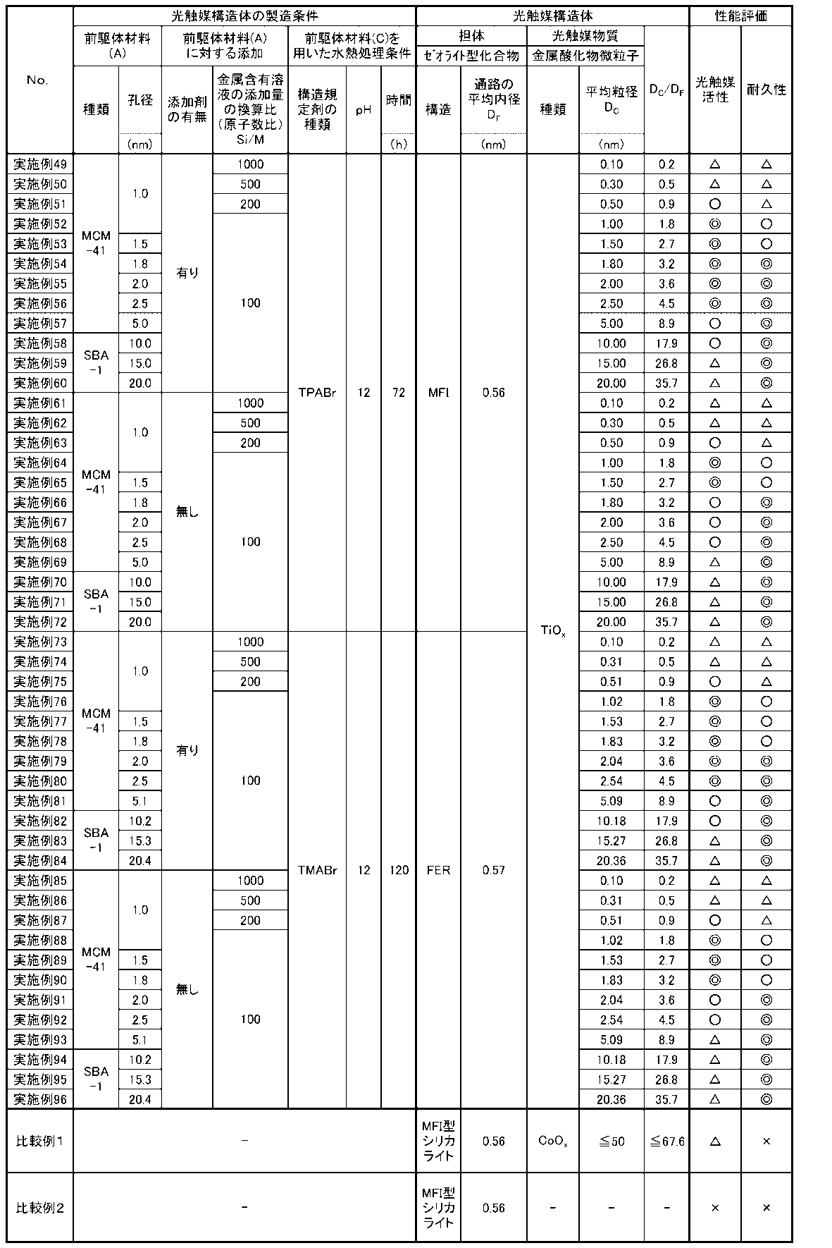
表1および2から明らかなように、断面観察により担体の内部に光触媒物質が保持されていることが確認された光触媒構造体(実施例1~96)は、単に光触媒物質が担体の外表面に付着しているだけの光触媒構造体(比較例1、2)と比較して、優れた光触媒活性を示し、光触媒としての耐久性にも優れていることが分かった。
一方、光触媒物質を何ら有していない比較例2の担体そのものは、光触媒活性は殆ど示さず、実施例1~96の光触媒構造体と比較して、光触媒活性および耐久性の双方が劣っていた。
また、担体の外表面にのみ光触媒物質を付着させた比較例1、2の光触媒構造体は、光触媒物質を何ら有していない比較例2の担体そのものと比較して、光触媒活性は改善されるものの、実施例1~96の光触媒構造体に比べて、光触媒としての耐久性は劣っていた。
また、上記のような優れた光触媒活性を有する光触媒構造体を含有する実施例1~96の光触媒構造体組成物によれば、優れた防汚性を発揮し得る、光触媒層が得られる。
また、光触媒物質が担体内に保持されている光触媒構造体を含む実施例1~96の光触媒構造体組成物では、バインダ材料と光触媒物質とが直接接触することが効果的に防止されている。そのため、光触媒構造体組成物では、バインダ材料の劣化が抑制され、長期にわたり優れた安定性が発揮されることがわかった。これに対して、光触媒物質が担体の外表面に付着しているだけの光触媒構造体を含む比較例1、2の光触媒構造体組成物では、バインダ材料と光触媒物質とが直接接触する構成となるため、光触媒構造体組成物に光が照射される環境下では、光触媒物質の光触媒活性によりバインダ材料が劣化し易く、実施例1~96の光触媒構造体組成物に比べて、安定性に劣ることが確認された。
さらに、実施例1~96の光触媒被覆材を構成する光触媒層に含まれる光触媒構造体は、断面観察により担体の内部に光触媒物質が保持されていることが確認された。このような光触媒構造体は、比較例1、2の光触媒被覆材を構成する光触媒層に含まれる、単に光触媒物質が担体の外表面に付着しているだけの光触媒構造体に比べて、優れた光触媒活性を示し、光触媒としての耐久性にも優れていることが分かった。
上記のような優れた光触媒活性を有する光触媒構造体を含有する光触媒層を備える実施例1~96の光触媒被覆材は、光触媒層の表面において優れた防汚性が発揮される。
また、このような光触媒被覆材では、光触媒物質は、担体の内部に保持されて、基材上に存在するため、基材と光触媒物質とが直接接触することが効果的に防止されている。そのため、光触媒被覆材では、基材の劣化が抑制され、長期にわたり優れた安定性が発揮されることがわかった。これに対して、光触媒物質が担体の外表面に付着しているだけの光触媒構造体を含有する光触媒層を備える比較例1、2の光触媒被覆材では、基材と光触媒物質とが直接接触する構成となるため、光触媒被覆材に光が照射される環境下では、光触媒物質の光触媒活性により基材が劣化し易く、実施例1~96の光触媒被覆材に比べて、安定性に劣ることがわかった。
[他の実施態様]
アセトアルデヒドを分解するために光触媒構造体を使用する方法であって、
前記光触媒構造体が、ゼオライト型化合物で構成される多孔質構造の担体と、前記担体に内在する金属微粒子とを備え、前記担体が互いに連通する通路を有し、前記金属微粒子が、前記担体の少なくとも前記通路の拡径部に存在していることを特徴とする、光触媒構造体を使用する方法。
アセトアルデヒドを分解するために光触媒構造体を使用する方法であって、
前記光触媒構造体が、ゼオライト型化合物で構成される多孔質構造の担体と、前記担体に内在する金属微粒子とを備え、前記担体が互いに連通する通路を有し、前記金属微粒子が、前記担体の少なくとも前記通路の拡径部に存在していることを特徴とする、光触媒構造体を使用する方法。
1 光触媒構造体
10 担体
10a 外表面
11 通路
11a 孔
12 拡径部
20 光触媒物質
30 光触媒物質
DC 平均粒径
DF 平均内径
DE 内径
10 担体
10a 外表面
11 通路
11a 孔
12 拡径部
20 光触媒物質
30 光触媒物質
DC 平均粒径
DF 平均内径
DE 内径
Claims (27)
- ゼオライト型化合物で構成される多孔質構造の担体と、
前記担体に内在する少なくとも1つの光触媒物質と、
を備え、
前記担体が、互いに連通する通路を有し、
前記光触媒物質が、金属酸化物微粒子であり、かつ前記担体の少なくとも前記通路に存在していることを特徴とする光触媒構造体。 - 前記通路は、拡径部を有し、かつ
前記光触媒物質が、少なくとも前記拡径部に存在していることを特徴とする、請求項1に記載の光触媒構造体。 - 前記拡径部は、前記一次元孔、前記二次元孔及び前記三次元孔のうちのいずれかを構成する複数の孔同士を連通している、請求項2に記載の光触媒構造体。
- 前記金属酸化物微粒子がチタンまたはそれら含む合金酸化物を含んでなることを特徴とする請求項1~3のいずれか1項に記載の光触媒構造体。
- 前記金属酸化物微粒子の平均粒径が、前記通路の平均内径よりも大きく、かつ前記拡径部の内径以下であることを特徴とする、請求項1~4のいずれか1項に記載の光触媒構造体。
- 前記金属酸化物微粒子の金属元素(M)が、前記触媒構造体に対して0.5~2.5質量%で含有されていることを特徴とする、請求項1~5のいずれか1項に記載の水素化脱硫用触媒構造体。
- 前記金属酸化物微粒子の平均粒径が、0.1nm~50nmであることを特徴とする、請求項1~6のいずれか1項に記載の光触媒構造体。
- 前記金属酸化物微粒子の平均粒径が、0.45nm~14.0nmであることを特徴とする、請求項7に記載の水素化脱硫用触媒構造体。
- 前記通路の平均内径に対する前記金属酸化物微粒子の平均粒径の割合が、0.06~500であることを特徴とする、請求項1~8のいずれか1項に記載の光触媒構造体。
- 前記通路の平均内径に対する前記金属酸化物微粒子の平均粒径の割合が、0.1~45であることを特徴とする、請求項9に記載の光触媒構造体。
- 前記通路の平均内径に対する前記金属酸化物微粒子の平均粒径の割合が、1.7~4.5であることを特徴とする、請求項10に記載の光触媒構造体。
- 前記通路は、前記ゼオライト型化合物の骨格構造によって画定される一次元孔、二次元孔及び三次元孔のうちのいずれかと、前記一次元孔、前記二次元孔及び前記三次元孔のうちのいずれとも異なる拡径部を有し、
前記通路の平均内径は、0.1nm~1.5nmであり、
前記拡径部の内径は、0.5nm~50nmであることを特徴とする、請求項1~11のいずれか1項に記載の光触媒構造体。 - 前記担体の外表面に保持された少なくとも1つの他の光触媒物質を更に備えることを特徴とする、請求項1~12のいずれか1項に記載の光触媒構造体。
- 前記担体に内在する前記少なくとも1つの光触媒物質の含有量が、前記担体の外表面に保持された前記少なくとも1つの他の光触媒物質の含有量よりも多いことを特徴とする、請求項13に記載の光触媒構造体。
- 前記ゼオライト型化合物は、ケイ酸塩化合物であることを特徴とする、請求項1~14のいずれか1項に記載の光触媒構造体。
- 分散媒中に分散されてなることを特徴とする、請求項1~15のいずれか1項に記載の光触媒構造体。
- 請求項1~16のいずれか1項に記載の光触媒構造体と、バインダ材料とを含有することを特徴とする光触媒構造体組成物。
- 前記バインダ材料が、有機系バインダであることを特徴とする、請求項17に記載の光触媒構造体組成物。
- 基材と、該基材上に形成された光触媒層とを備える光触媒被覆材であって、
前記光触媒層が、請求項1~16のいずれか1項に記載の光触媒構造体を含有することを特徴とする、光触媒被覆材。 - 前記基材が、建材であることを特徴とする、請求項19に記載の光触媒被覆材。
- ゼオライト型化合物で構成される多孔質構造の担体を得るための前駆体材料(A)に金属含有溶液が含浸された前駆体材料(B)を焼成する焼成工程と、
前記前駆体材料(B)を焼成して得られた前駆体材料(C)を水熱処理する水熱処理工程と、
を有することを特徴とする光触媒構造体の製造方法。 - 前記焼成工程の前に、非イオン性界面活性剤を、前記前駆体材料(A)に対して50~500質量%添加することを特徴とする、請求項21に記載の光触媒構造体の製造方法。
- 前記焼成工程の前に、前記前駆体材料(A)に前記金属含有溶液を複数回に分けて添加することで、前記前駆体材料(A)に前記金属含有溶液を含浸させることを特徴とする、請求項21又は22に記載の光触媒構造体の製造方法。
- 前記焼成工程の前に前記前駆体材料(A)に前記金属含有溶液を含浸させる際に、前記前駆体材料(A)に添加する前記金属含有溶液の添加量を、前記前駆体材料(A)に添加する前記金属含有溶液中に含まれる金属元素(M)に対する、前記前駆体材料(A)を構成するケイ素(Si)の比(原子数比Si/M)に換算して、10~1000となるように調整することを特徴とする、請求項21~23のいずれか1項に記載の光触媒構造体の製造方法。
- 前記水熱処理工程において、前記前駆体材料(C)と構造規定剤とを混合することを特徴とする、請求項21に記載の光触媒構造体の製造方法。
- 前記水熱処理工程が塩基性雰囲気下で行われることを特徴とする、請求項21に記載の光触媒構造体の製造方法。
- 請求項1から請求項16のいずれか1項に記載の光触媒を用いてアルデヒド類を分解することを特徴とする、アルデヒド類の分解方法。
Priority Applications (4)
| Application Number | Priority Date | Filing Date | Title |
|---|---|---|---|
| JP2019521330A JPWO2018221702A1 (ja) | 2017-05-31 | 2018-05-31 | 光触媒構造体、光触媒構造体組成物、光触媒被覆材、光触媒構造体の製造方法及びアルデヒド類の分解方法 |
| CN201880036071.3A CN110709168A (zh) | 2017-05-31 | 2018-05-31 | 光催化剂结构体、光催化剂结构体组合物、光催化剂包覆材料、光催化剂结构体的制造方法以及醛类的分解方法 |
| EP18810519.1A EP3632558A4 (en) | 2017-05-31 | 2018-05-31 | PHOTOCATALYST STRUCTURE, PHOTOCATALYST STRUCTURE COMPOSITION, PHOTOCATALYST COATING MATERIAL, METHOD OF MANUFACTURING PHOTOCATALYST STRUCTURE AND ALDEHYDE DECOMPOSITION |
| US16/698,567 US20200114336A1 (en) | 2017-05-31 | 2019-11-27 | Structured photocatalyst, structured photocatalyst composition, photocatalyst coated material, method for producing structured photocatalyst, and method for decomposing aldehydes |
Applications Claiming Priority (6)
| Application Number | Priority Date | Filing Date | Title |
|---|---|---|---|
| JP2017-108637 | 2017-05-31 | ||
| JP2017108636 | 2017-05-31 | ||
| JP2017-108638 | 2017-05-31 | ||
| JP2017108638 | 2017-05-31 | ||
| JP2017108637 | 2017-05-31 | ||
| JP2017-108636 | 2017-05-31 |
Related Child Applications (1)
| Application Number | Title | Priority Date | Filing Date |
|---|---|---|---|
| US16/698,567 Continuation US20200114336A1 (en) | 2017-05-31 | 2019-11-27 | Structured photocatalyst, structured photocatalyst composition, photocatalyst coated material, method for producing structured photocatalyst, and method for decomposing aldehydes |
Publications (1)
| Publication Number | Publication Date |
|---|---|
| WO2018221702A1 true WO2018221702A1 (ja) | 2018-12-06 |
Family
ID=64455989
Family Applications (1)
| Application Number | Title | Priority Date | Filing Date |
|---|---|---|---|
| PCT/JP2018/021090 Ceased WO2018221702A1 (ja) | 2017-05-31 | 2018-05-31 | 光触媒構造体、光触媒構造体組成物、光触媒被覆材、光触媒構造体の製造方法及びアルデヒド類の分解方法 |
Country Status (5)
| Country | Link |
|---|---|
| US (1) | US20200114336A1 (ja) |
| EP (1) | EP3632558A4 (ja) |
| JP (1) | JPWO2018221702A1 (ja) |
| CN (1) | CN110709168A (ja) |
| WO (1) | WO2018221702A1 (ja) |
Cited By (1)
| Publication number | Priority date | Publication date | Assignee | Title |
|---|---|---|---|---|
| JPWO2021085073A1 (ja) * | 2019-10-29 | 2021-05-06 |
Families Citing this family (15)
| Publication number | Priority date | Publication date | Assignee | Title |
|---|---|---|---|---|
| EP3632554A4 (en) | 2017-05-31 | 2021-04-21 | Furukawa Electric Co., Ltd. | OXIDATION CATALYST STRUCTURE FOR EXHAUST GAS CLEANING AND MANUFACTURING PROCESSES FOR IT, EXHAUST GAS TREATMENT DEVICE FOR VEHICLES, CATALYST FORMED BODIES AND GAS PURIFICATION PROCESSES |
| CN110730687A (zh) | 2017-05-31 | 2020-01-24 | 古河电气工业株式会社 | 催化裂化用或加氢脱硫用催化剂结构体、具有该催化剂结构体的催化裂化装置以及加氢脱硫装置、以及催化裂化用或加氢脱硫用催化剂结构体的制造方法 |
| CN110678259A (zh) | 2017-05-31 | 2020-01-10 | 国立大学法人北海道大学 | 功能性结构体以及功能性结构体的制造方法 |
| JP7316934B2 (ja) | 2017-05-31 | 2023-07-28 | 古河電気工業株式会社 | 水素化脱硫用触媒構造体、該触媒構造体を備える水素化脱硫装置及び水素化脱硫用触媒構造体の製造方法 |
| WO2018221707A1 (ja) | 2017-05-31 | 2018-12-06 | 古河電気工業株式会社 | 水蒸気改質用触媒構造体、該水蒸気改質用触媒構造体を備える改質装置、及び水蒸気改質用触媒構造体の製造方法 |
| WO2018221693A1 (ja) | 2017-05-31 | 2018-12-06 | 国立大学法人北海道大学 | 機能性構造体及び機能性構造体の製造方法 |
| CN110678258A (zh) | 2017-05-31 | 2020-01-10 | 国立大学法人北海道大学 | 功能性结构体以及功能性结构体的制造方法 |
| WO2018221706A1 (ja) | 2017-05-31 | 2018-12-06 | 古河電気工業株式会社 | メタノール改質触媒構造体、メタノール改質用装置、メタノール改質触媒構造体の製造方法及びオレフィンまたは芳香族炭化水素の少なくとも一方の製造方法 |
| JP7306990B2 (ja) | 2017-05-31 | 2023-07-11 | 古河電気工業株式会社 | Coシフトもしくは逆シフト触媒構造体及びその製造方法、coシフトまたは逆シフト反応装置、二酸化炭素と水素の製造方法、並びに一酸化炭素と水の製造方法 |
| EP3632548A4 (en) | 2017-05-31 | 2021-03-03 | National University Corporation Hokkaido University | FUNCTIONAL STRUCTURE AND MANUFACTURING PROCESS FOR FUNCTIONAL STRUCTURE |
| GB2600935A (en) * | 2020-11-11 | 2022-05-18 | Environmental Control Coatings Ltd | Air treatment unit |
| CN113813954B (zh) * | 2021-09-26 | 2023-06-20 | 南京大学 | 一种层状CeO2-x材料及其制备方法和应用 |
| CN116086079A (zh) * | 2021-11-05 | 2023-05-09 | 云米互联科技(广东)有限公司 | 一种冰箱延鲜模块、冰箱 |
| CN114570426A (zh) * | 2022-01-10 | 2022-06-03 | 湖南醇润生物科技有限公司 | 一种光催化剂及其制备方法和应用 |
| CN117463354B (zh) * | 2023-10-30 | 2025-11-25 | 沈阳大学 | 一种复合光催化产氢材料MoO3/CuO的制备方法 |
Citations (14)
| Publication number | Priority date | Publication date | Assignee | Title |
|---|---|---|---|---|
| JPH1133412A (ja) * | 1997-07-23 | 1999-02-09 | Unitika Ltd | 金属担持触媒の製造方法 |
| JP2005270734A (ja) * | 2004-03-23 | 2005-10-06 | Hiroshima Univ | 光触媒複合体およびこれを用いた有機物質変換方法 |
| JP2005314208A (ja) * | 2004-03-29 | 2005-11-10 | Hiroshima Univ | 複合多孔体およびその製造方法、並びにこれを用いた有機物質変換方法 |
| JP2006021994A (ja) | 1993-12-28 | 2006-01-26 | Toto Ltd | 光触媒機能を有する多機能材の製造方法 |
| WO2007023558A1 (ja) * | 2005-08-26 | 2007-03-01 | Suminoe Textile Co., Ltd. | 酸化タングステン系光触媒及びその製造方法並びに消臭・防汚機能を有する繊維布帛 |
| JP2007519799A (ja) | 2004-01-30 | 2007-07-19 | ミレニアム ケミカルズ ユーケー ホールディングス リミテッド | 表面の汚れを除去する特性を持つコーティング組成物 |
| WO2009096548A1 (ja) * | 2008-02-01 | 2009-08-06 | Shimadzu System Solutions Co., Ltd. | 銀-酸化チタン-ゼオライト吸着分解素材及びその製造方法 |
| WO2010097108A1 (en) * | 2009-02-27 | 2010-09-02 | Haldor Topsøe A/S | Process for the preparation of hybrid zeolite or zeolite-like materials |
| JP2012170951A (ja) * | 2011-02-24 | 2012-09-10 | Kyushu Univ | 光触媒−吸着材複合粉体 |
| JP2012210557A (ja) | 2011-03-30 | 2012-11-01 | Panasonic Corp | 撥水性光触媒組成物及び撥水性光触媒塗膜 |
| WO2013115213A1 (ja) | 2012-01-31 | 2013-08-08 | 国立大学法人大阪大学 | 酸化チタンメソ結晶 |
| JP2016087522A (ja) * | 2014-10-31 | 2016-05-23 | 地方独立行政法人東京都立産業技術研究センター | 量子ドット複合光触媒 |
| WO2016181622A1 (ja) | 2015-05-12 | 2016-11-17 | 日本曹達株式会社 | 光触媒含有塗布液及び光触媒担持構造体 |
| CN106362787A (zh) * | 2016-08-06 | 2017-02-01 | 浙江大学 | 一种沸石固载光催化剂的制备方法 |
Family Cites Families (2)
| Publication number | Priority date | Publication date | Assignee | Title |
|---|---|---|---|---|
| JP2012250133A (ja) * | 2009-09-30 | 2012-12-20 | Toto Ltd | 光触媒塗装体およびそのための光触媒コーティング液 |
| CA2851988C (en) * | 2011-10-21 | 2019-05-21 | Igtl Technology Ltd | Methods of preparation and forming supported active metal catalysts and precursors |
-
2018
- 2018-05-31 WO PCT/JP2018/021090 patent/WO2018221702A1/ja not_active Ceased
- 2018-05-31 JP JP2019521330A patent/JPWO2018221702A1/ja active Pending
- 2018-05-31 EP EP18810519.1A patent/EP3632558A4/en not_active Withdrawn
- 2018-05-31 CN CN201880036071.3A patent/CN110709168A/zh active Pending
-
2019
- 2019-11-27 US US16/698,567 patent/US20200114336A1/en not_active Abandoned
Patent Citations (14)
| Publication number | Priority date | Publication date | Assignee | Title |
|---|---|---|---|---|
| JP2006021994A (ja) | 1993-12-28 | 2006-01-26 | Toto Ltd | 光触媒機能を有する多機能材の製造方法 |
| JPH1133412A (ja) * | 1997-07-23 | 1999-02-09 | Unitika Ltd | 金属担持触媒の製造方法 |
| JP2007519799A (ja) | 2004-01-30 | 2007-07-19 | ミレニアム ケミカルズ ユーケー ホールディングス リミテッド | 表面の汚れを除去する特性を持つコーティング組成物 |
| JP2005270734A (ja) * | 2004-03-23 | 2005-10-06 | Hiroshima Univ | 光触媒複合体およびこれを用いた有機物質変換方法 |
| JP2005314208A (ja) * | 2004-03-29 | 2005-11-10 | Hiroshima Univ | 複合多孔体およびその製造方法、並びにこれを用いた有機物質変換方法 |
| WO2007023558A1 (ja) * | 2005-08-26 | 2007-03-01 | Suminoe Textile Co., Ltd. | 酸化タングステン系光触媒及びその製造方法並びに消臭・防汚機能を有する繊維布帛 |
| WO2009096548A1 (ja) * | 2008-02-01 | 2009-08-06 | Shimadzu System Solutions Co., Ltd. | 銀-酸化チタン-ゼオライト吸着分解素材及びその製造方法 |
| WO2010097108A1 (en) * | 2009-02-27 | 2010-09-02 | Haldor Topsøe A/S | Process for the preparation of hybrid zeolite or zeolite-like materials |
| JP2012170951A (ja) * | 2011-02-24 | 2012-09-10 | Kyushu Univ | 光触媒−吸着材複合粉体 |
| JP2012210557A (ja) | 2011-03-30 | 2012-11-01 | Panasonic Corp | 撥水性光触媒組成物及び撥水性光触媒塗膜 |
| WO2013115213A1 (ja) | 2012-01-31 | 2013-08-08 | 国立大学法人大阪大学 | 酸化チタンメソ結晶 |
| JP2016087522A (ja) * | 2014-10-31 | 2016-05-23 | 地方独立行政法人東京都立産業技術研究センター | 量子ドット複合光触媒 |
| WO2016181622A1 (ja) | 2015-05-12 | 2016-11-17 | 日本曹達株式会社 | 光触媒含有塗布液及び光触媒担持構造体 |
| CN106362787A (zh) * | 2016-08-06 | 2017-02-01 | 浙江大学 | 一种沸石固载光催化剂的制备方法 |
Non-Patent Citations (1)
| Title |
|---|
| See also references of EP3632558A4 |
Cited By (2)
| Publication number | Priority date | Publication date | Assignee | Title |
|---|---|---|---|---|
| JPWO2021085073A1 (ja) * | 2019-10-29 | 2021-05-06 | ||
| JP7344978B2 (ja) | 2019-10-29 | 2023-09-14 | 京セラ株式会社 | セラミック構造体、吸着ノズル、カッター、ピンセット、摩耗検出器、粉体除電装置、粉体製造装置、リフトピン、搬送ハンドおよび繊維ガイド |
Also Published As
| Publication number | Publication date |
|---|---|
| CN110709168A (zh) | 2020-01-17 |
| EP3632558A1 (en) | 2020-04-08 |
| EP3632558A4 (en) | 2021-03-17 |
| US20200114336A1 (en) | 2020-04-16 |
| JPWO2018221702A1 (ja) | 2020-03-26 |
Similar Documents
| Publication | Publication Date | Title |
|---|---|---|
| US20200114336A1 (en) | Structured photocatalyst, structured photocatalyst composition, photocatalyst coated material, method for producing structured photocatalyst, and method for decomposing aldehydes | |
| JP7282027B2 (ja) | アンモニア分解触媒構造体及び燃料電池 | |
| JP7269169B2 (ja) | メタノール改質触媒構造体、メタノール改質用装置、メタノール改質触媒構造体の製造方法及びオレフィンまたは芳香族炭化水素の少なくとも一方の製造方法 | |
| AU2018276618B2 (en) | Functional structure and production method for functional structure | |
| WO2018221696A1 (ja) | 排気ガス浄化用酸化触媒構造体及びその製造方法、自動車の排気ガス処理装置、触媒成形体、並びに気体浄化方法 | |
| WO2018221690A1 (ja) | 機能性構造体及び機能性構造体の製造方法 | |
| WO2018221704A1 (ja) | 芳香族炭化水素製造用触媒構造体、その芳香族炭化水素製造用触媒構造体を備える芳香族炭化水素製造装置、芳香族炭化水素製造用触媒構造体の製造方法及び芳香族炭化水素の製造方法 | |
| WO2018221697A1 (ja) | 合成ガス製造用触媒構造体、該合成ガス製造用触媒構造体を備える合成ガス製造装置及び合成ガス製造用触媒構造体の製造方法 | |
| JP7361604B2 (ja) | フィッシャー・トロプシュ合成触媒構造体、その製造方法及び該触媒構造体を用いた液体炭化水素の製造方法、並びに該触媒構造体を有する炭化水素製造装置 | |
| WO2018221699A1 (ja) | アンモニア合成触媒構造体及びその製造方法、アンモニア合成装置並びにアンモニアの合成方法 | |
| JP7316766B2 (ja) | N2o分解用触媒構造体及びその製造方法、並びに該n2o分解用触媒構造体を有するn2o除去装置 | |
| JP7254453B2 (ja) | アルカンの脱水素化触媒構造体及びその製造方法、並びに該脱水素化触媒構造体を有するアルケン製造装置 | |
| JP7295615B2 (ja) | 揮発性有機物質用触媒構造体及びその製造方法ならびに揮発性有機物質除去装置 | |
| JP7366431B2 (ja) | 触媒構造体およびその製造方法、ならびに該触媒構造体を用いた炭化水素の製造方法 | |
| JP7407713B2 (ja) | 軽質炭化水素合成触媒構造体、軽質炭化水素製造装置及び軽質炭化水素の製造方法 | |
| JP2018202406A (ja) | Voc酸化触媒構造体及びその製造方法、ならびに、voc処理装置及び触媒成形体 | |
| JP2018202408A (ja) | NOx分解触媒構造体及びその製造方法、ならびに、NOx処理装置及び触媒成形体 | |
| JP7327909B2 (ja) | No分解触媒構造体、no分解処理装置及びno分解触媒構造体の製造方法 | |
| JP7348836B2 (ja) | 流動接触分解用構造体及びその製造方法、並びに、これを備える流動接触分解用装置 | |
| JP7327910B2 (ja) | Co処理用触媒構造体及びその製造方法、並びに該co処理用触媒構造体を有するco処理装置 | |
| JP7348718B2 (ja) | 自動車用還元触媒構造体、自動車用排気ガス処理装置、触媒成形体及び自動車用還元触媒構造体の製造方法 | |
| JP7635943B2 (ja) | 機能性構造体及び機能性構造体の製造方法 | |
| JP7295614B2 (ja) | Fcc副生分解油から生成される芳香族化合物製造用触媒構造体、該触媒構造体を有する芳香族化合物製造装置及び芳香族化合物製造用触媒構造体の製造方法 | |
| WO2018221705A1 (ja) | 水素化分解用触媒構造体、その水素化分解用触媒構造体を備える水素化分解装置及び水素化分解用触媒構造体の製造方法 | |
| JP7644925B2 (ja) | 機能性構造体 |
Legal Events
| Date | Code | Title | Description |
|---|---|---|---|
| 121 | Ep: the epo has been informed by wipo that ep was designated in this application |
Ref document number: 18810519 Country of ref document: EP Kind code of ref document: A1 |
|
| ENP | Entry into the national phase |
Ref document number: 2019521330 Country of ref document: JP Kind code of ref document: A |
|
| NENP | Non-entry into the national phase |
Ref country code: DE |
|
| ENP | Entry into the national phase |
Ref document number: 2018810519 Country of ref document: EP Effective date: 20200102 |