WO2018225697A1 - 車両内装用複合材 - Google Patents
車両内装用複合材 Download PDFInfo
- Publication number
- WO2018225697A1 WO2018225697A1 PCT/JP2018/021416 JP2018021416W WO2018225697A1 WO 2018225697 A1 WO2018225697 A1 WO 2018225697A1 JP 2018021416 W JP2018021416 W JP 2018021416W WO 2018225697 A1 WO2018225697 A1 WO 2018225697A1
- Authority
- WO
- WIPO (PCT)
- Prior art keywords
- skin material
- fold
- composite material
- main surface
- folds
- Prior art date
- Legal status (The legal status is an assumption and is not a legal conclusion. Google has not performed a legal analysis and makes no representation as to the accuracy of the status listed.)
- Ceased
Links
Images


Classifications
-
- B—PERFORMING OPERATIONS; TRANSPORTING
- B32—LAYERED PRODUCTS
- B32B—LAYERED PRODUCTS, i.e. PRODUCTS BUILT-UP OF STRATA OF FLAT OR NON-FLAT, e.g. CELLULAR OR HONEYCOMB, FORM
- B32B5/00—Layered products characterised by the non- homogeneity or physical structure, i.e. comprising a fibrous, filamentary, particulate or foam layer; Layered products characterised by having a layer differing constitutionally or physically in different parts
- B32B5/02—Layered products characterised by the non- homogeneity or physical structure, i.e. comprising a fibrous, filamentary, particulate or foam layer; Layered products characterised by having a layer differing constitutionally or physically in different parts characterised by structural features of a fibrous or filamentary layer
- B32B5/024—Woven fabric
-
- B—PERFORMING OPERATIONS; TRANSPORTING
- B32—LAYERED PRODUCTS
- B32B—LAYERED PRODUCTS, i.e. PRODUCTS BUILT-UP OF STRATA OF FLAT OR NON-FLAT, e.g. CELLULAR OR HONEYCOMB, FORM
- B32B3/00—Layered products comprising a layer with external or internal discontinuities or unevennesses, or a layer of non-planar shape; Layered products comprising a layer having particular features of form
- B32B3/26—Layered products comprising a layer with external or internal discontinuities or unevennesses, or a layer of non-planar shape; Layered products comprising a layer having particular features of form characterised by a particular shape of the outline of the cross-section of a continuous layer; characterised by a layer with cavities or internal voids ; characterised by an apertured layer
- B32B3/28—Layered products comprising a layer with external or internal discontinuities or unevennesses, or a layer of non-planar shape; Layered products comprising a layer having particular features of form characterised by a particular shape of the outline of the cross-section of a continuous layer; characterised by a layer with cavities or internal voids ; characterised by an apertured layer characterised by a layer comprising a deformed thin sheet, i.e. the layer having its entire thickness deformed out of the plane, e.g. corrugated, crumpled
-
- B—PERFORMING OPERATIONS; TRANSPORTING
- B32—LAYERED PRODUCTS
- B32B—LAYERED PRODUCTS, i.e. PRODUCTS BUILT-UP OF STRATA OF FLAT OR NON-FLAT, e.g. CELLULAR OR HONEYCOMB, FORM
- B32B5/00—Layered products characterised by the non- homogeneity or physical structure, i.e. comprising a fibrous, filamentary, particulate or foam layer; Layered products characterised by having a layer differing constitutionally or physically in different parts
- B32B5/02—Layered products characterised by the non- homogeneity or physical structure, i.e. comprising a fibrous, filamentary, particulate or foam layer; Layered products characterised by having a layer differing constitutionally or physically in different parts characterised by structural features of a fibrous or filamentary layer
-
- B—PERFORMING OPERATIONS; TRANSPORTING
- B32—LAYERED PRODUCTS
- B32B—LAYERED PRODUCTS, i.e. PRODUCTS BUILT-UP OF STRATA OF FLAT OR NON-FLAT, e.g. CELLULAR OR HONEYCOMB, FORM
- B32B5/00—Layered products characterised by the non- homogeneity or physical structure, i.e. comprising a fibrous, filamentary, particulate or foam layer; Layered products characterised by having a layer differing constitutionally or physically in different parts
- B32B5/22—Layered products characterised by the non- homogeneity or physical structure, i.e. comprising a fibrous, filamentary, particulate or foam layer; Layered products characterised by having a layer differing constitutionally or physically in different parts characterised by the presence of two or more layers which are next to each other and are fibrous, filamentary, formed of particles or foamed
- B32B5/24—Layered products characterised by the non- homogeneity or physical structure, i.e. comprising a fibrous, filamentary, particulate or foam layer; Layered products characterised by having a layer differing constitutionally or physically in different parts characterised by the presence of two or more layers which are next to each other and are fibrous, filamentary, formed of particles or foamed one layer being a fibrous or filamentary layer
- B32B5/26—Layered products characterised by the non- homogeneity or physical structure, i.e. comprising a fibrous, filamentary, particulate or foam layer; Layered products characterised by having a layer differing constitutionally or physically in different parts characterised by the presence of two or more layers which are next to each other and are fibrous, filamentary, formed of particles or foamed one layer being a fibrous or filamentary layer another layer next to it also being fibrous or filamentary
-
- B—PERFORMING OPERATIONS; TRANSPORTING
- B32—LAYERED PRODUCTS
- B32B—LAYERED PRODUCTS, i.e. PRODUCTS BUILT-UP OF STRATA OF FLAT OR NON-FLAT, e.g. CELLULAR OR HONEYCOMB, FORM
- B32B7/00—Layered products characterised by the relation between layers; Layered products characterised by the relative orientation of features between layers, or by the relative values of a measurable parameter between layers, i.e. products comprising layers having different physical, chemical or physicochemical properties; Layered products characterised by the interconnection of layers
- B32B7/04—Interconnection of layers
- B32B7/12—Interconnection of layers using interposed adhesives or interposed materials with bonding properties
-
- B—PERFORMING OPERATIONS; TRANSPORTING
- B60—VEHICLES IN GENERAL
- B60R—VEHICLES, VEHICLE FITTINGS, OR VEHICLE PARTS, NOT OTHERWISE PROVIDED FOR
- B60R13/00—Elements for body-finishing, identifying, or decorating; Arrangements or adaptations for advertising purposes
- B60R13/02—Internal Trim mouldings ; Internal Ledges; Wall liners for passenger compartments; Roof liners
-
- B—PERFORMING OPERATIONS; TRANSPORTING
- B32—LAYERED PRODUCTS
- B32B—LAYERED PRODUCTS, i.e. PRODUCTS BUILT-UP OF STRATA OF FLAT OR NON-FLAT, e.g. CELLULAR OR HONEYCOMB, FORM
- B32B2605/00—Vehicles
- B32B2605/003—Interior finishings
Definitions
- the present invention relates to a composite material used for the interior of a vehicle.
- Patent Document 1 teaches forming irregularities in a skin material made of polyurethane foam.
- An object of the present invention is to provide a composite material having a three-dimensional and high-class design and having wear resistance suitable for a vehicle interior material.
- One aspect of the present invention is a composite material for vehicle interior, which is disposed on the outermost side of one of the composite materials, and includes a first main surface and a second main surface opposite to the first main surface.
- first folds folded back with the first main surface of the skin material facing outward
- second folds folded back with the first main surface facing inward
- the first folds are parallel to each other, or the acute angle ⁇ 1 formed between them is 10 ° or less
- the adjacent second folds are parallel to each other, or the acute angle ⁇ 2 formed between them is 10 ° or less
- the adjacent first fold line and the second fold line are parallel to each other, or the acute angle ⁇ 12 formed by them is 10 ° or less.
- the present invention relates to a composite material for vehicle interior.
- the skin material further includes a plurality of third folds that fold back with the first main surface of the skin material facing outward, and a plurality of fourth folds that fold back with the first main surface facing inward.
- the adjacent third fold line and the fourth fold line are parallel to each other, or the acute angle ⁇ 34 formed by them is 10 ° or less, and the third fold line and the fourth fold line include a plurality of the first fold line and the fourth fold line. It is preferable to cross one fold.
- the angle ⁇ 13 formed by the first fold line and the third fold line is 90 °, or the smaller one of the angles ⁇ 13 formed by the first fold line and the third fold line, It is preferably 10 ° or more.
- the vehicle interior composite material further includes one or more intermediate materials interposed between the skin material and the backing material.
- the intermediate material preferably includes a fold corresponding to at least one of the first fold, the second fold, the third fold, and the fourth fold of the skin material.
- the fineness of the fibers exposed on the first main surface of the skin material is preferably 117 to 225 dtex.
- the skin material is a fabric formed by a first fiber and a second fiber intersecting with the first fiber, and the first fiber is continuous in the structure of the first main surface of the fabric.
- the pattern is arranged on the first main surface side of the three or more second fibers, and subsequently arranged on the second main surface side of the two or less continuous second fibers. It is preferable.
- the composite material for vehicle interior according to the present invention is excellent in design because the skin material has a plurality of folds. Furthermore, the composite material has wear resistance suitable for a vehicle interior material. In addition, the crease is sharp and the shape retention is excellent.
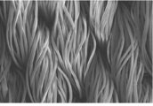
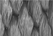
- FIG. 1 It is a top view which shows typically a part of composite material for vehicle interior which concerns on embodiment of this invention. It is a perspective view which shows typically a part of composite material among the other vehicle interior composite materials which concern on embodiment of this invention. It is a top view which shows typically a part of composite material for vehicle interior shown in FIG. It is the photograph (100-times multiplication factor) which image
- SEM scanning electron microscope
- the composite material for vehicle interior (hereinafter sometimes simply referred to as a composite material) is disposed on the outermost side of one of the composite materials, and is opposite to the first main surface and the first main surface.
- the composite material is used as a vehicle interior material such as a ceiling material, a door material, a seat material, and a floor material inside the vehicle. At this time, the composite material is disposed so that the skin material faces the interior space of the vehicle.
- the skin material includes a plurality of first folds and second folds.
- the first fold folds the skin material with the first main surface outward
- the second fold folds the skin material with the first main surface inside.
- the skin material is formed of a fiber structure. Therefore, it has excellent wear resistance.
- the crease is formed by folding the skin material into a desired shape and then performing a heat treatment.
- the skin material is easily folded, so that a sharp crease can be formed in a desired shape. That is, such a skin material can be easily folded into a desired shape and has high workability. Furthermore, the folds obtained are sharp and have excellent moldability.
- the backing has a function of holding the formed folds by being laminated on a skin material provided with a plurality of first folds and second folds. Therefore, it is excellent in fold shape retention.
- the skin material includes a plurality of first folds and second folds, respectively.
- One fold (first fold) is formed in the skin material by the first fold and the second fold adjacent thereto.
- Adjacent first folds are parallel to each other, or the acute angle ⁇ 1 formed by them is 10 ° or less. Further, the adjacent second folds are parallel to each other, or the acute angle ⁇ 2 formed by them is 10 ° or less. Further, the adjacent first fold line and the second fold line are parallel to each other, or the acute angle ⁇ 12 formed by them is 10 ° or less. That is, the adjacent first fold line and the second fold line are formed along substantially the same direction.
- the acute angle ⁇ 12 is an acute angle formed by a first fold and a second fold forming one first fold.
- the acute angle ⁇ 1 , the acute angle ⁇ 2, and the acute angle ⁇ 12 are set in accordance with a desired design within the above range.
- the acute angle ⁇ 1 and the acute angle ⁇ 2 may be, for example, 1 ° or more and 5 ° or less, respectively.
- the acute angle ⁇ 1 and the acute angle ⁇ 2 may be the same or different.
- the acute angle ⁇ 1 , the acute angle ⁇ 2 , and the acute angle ⁇ 12 may or may not be constant.
- Each acute angle is the maximum acute angle formed between the folds when the composite material 10 is viewed from the skin material 1 side. The same applies to the acute angle ⁇ 13 .
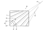
- FIG. 1 schematically shows a part of the composite material 10 in which the first fold line L1 and the second fold line L2 are formed from the skin material 1 side.
- FIG. 1 is a top view schematically showing a part of the composite material 10 according to the present embodiment.
- the acute angle ⁇ 1 and the acute angle ⁇ 2 are each about 5 °, and the acute angle ⁇ 12 (not shown) is approximately 0 °.
- the distance D 1 between the adjacent first folds L1, the distance D 2 between the adjacent second folds L2, and the distance D 12 between the adjacent first folds L1 and L2 are not particularly limited, It is set according to the desired design. Among these, from the viewpoint of design properties, the distance D 1 is preferably 1 to 20 cm. Similarly, the distance D 2 is preferably 1 to 20 cm. From the viewpoint of wear resistance and texture, the distance D 12 is preferably 0.5 to 5 cm. Each distance is the maximum distance between the folds when the composite material 10 is viewed from the skin material 1 side. The distance D 12 is the width of the first fold P1.
- the skin material is formed of a fiber structure such as a woven fabric, a knitted fabric, or a non-woven fabric.
- the skin material may be artificial leather, synthetic leather, or the like obtained by applying resin processing to the fiber structure, or may be a laminate of a plurality of fiber structures.
- the skin material is preferably a woven fabric.
- the curvature of the skin material is preferably 2% or less in both the vertical direction and the horizontal direction. If the bend is 2% or less, since the balance of elongation in the vertical direction and the horizontal direction of the skin material is good, the moldability is easily improved.
- the bend of the woven fabric or the knitted fabric may be measured according to JIS L 1096 8.12 (cloth bend).
- the structure is not particularly limited.
- the texture of the woven fabric include, for example, plain weaving, oblique weaving, and satin weaving that are Mihara tissues; a change structure of these Mihara tissues; a special structure such as satin weaving; and a mixed structure in which two or more of these are combined. it can.
- a twill pattern or its changed structure is preferable.
- the first fibers in the woven structure of the first main surface, have three or more continuous fibers. It is preferable to have a pattern that is arranged on the first main surface side of the second fiber and subsequently arranged on the second main surface side of two or less continuous second fibers. That is, in the woven structure of the first main surface, three or more first fibers (for example, warps) of the second fibers (for example, wefts) are continuously exposed in the direction along the first fibers. ing. Thereby, although the skin material itself is provided with unevenness due to each fold, local unevenness on the first main surface can be reduced.
- the first fibers continuous in the direction along the first fibers do not exceed five of the second fibers.
- the fibers constituting the skin material preferably contain a thermoplastic resin. This is because the moldability is easily improved.
- fibers containing a thermoplastic resin include synthetic fibers such as polyester fibers, polypropylene fibers, and nylon fibers, and semi-synthetic fibers such as acetate fibers and triacetate fibers. These may be used alone or in combination of two or more. Of these, synthetic fibers are preferable, polyester fibers are more preferable, and polyethylene terephthalate (PET) fibers are particularly preferable in terms of excellent physical properties (particularly strength, wear resistance, and heat resistance).
- the fiber structure may contain fibers other than thermoplastic fibers.
- thermoplastic fibers examples include natural fibers and recycled fibers.
- a plurality of types of fibers can be combined by techniques such as blending, blending, knit, knit, knit, and the like.
- the thermoplastic fiber occupies 50% by mass or more of the skin material.
- the fineness of the skin fiber is not particularly limited.
- the fineness of the skin fibers exposed on the first main surface of the skin material is preferably 117 to 225 dtex.
- the fineness of the skin fibers not exposed on the first main surface of the skin material is preferably 117 to 225 dtex from the viewpoints of wear resistance, workability and moldability.
- the single fiber fineness of the skin fiber is not particularly limited, but in particular, the single fiber fineness of the skin fiber exposed on the first main surface of the skin material is preferably 3 dtex or more. Thereby, abrasion resistance becomes easy to improve more.
- the upper limit of the single fiber fineness is not particularly limited, but 6 dtex is preferable and 4 dtex is more preferable from the viewpoint of the processability of the fold.
- the form of the skin fiber is not particularly limited.
- the skin fiber may be, for example, a short fiber such as a spun yarn, a long fiber such as a multifilament yarn or a monofilament yarn, or a long / short composite spun yarn combining a long fiber and a short fiber.
- the multifilament yarn may be twisted, or may be subjected to processing such as false twisting or liquid disturbance treatment.
- the thickness T1 when the crease of the skin material is stretched is not particularly limited.
- the thickness is preferably 0.5 to 1 mm from the viewpoint of durability and crease processability.
- the formability of the crease is also improved.
- the thickness T1 of the skin material may be the thickness of the skin material before crease formation.
- the thickness T1 of the skin material is obtained, for example, by averaging the thicknesses of any 10 locations of the skin material.
- the thickness of an arbitrary part of the skin material can be measured by, for example, PEACOCK H-30 (manufactured by Ozaki Mfg. Co., Ltd.). The same applies to the thickness T2 of the backing and the thickness T3 of the intermediate material.
- the mass per unit area (hereinafter simply referred to as mass W1) when the crease of the skin material is stretched is preferably 200 to 400 g / m 2 , and preferably 200 to More preferably, it is 300 g / m 2 . Thereby, abrasion resistance becomes easy to improve.
- the backing material is laminated on the skin material, and the first crease and the second crease formed on the skin material are fixed and held, thereby improving the shape retention of each fold.
- the form of the backing is not particularly limited, and examples thereof include the same material as the skin material. Among these, a fiber structure is preferable and a woven fabric is more preferable in that the shape retention of each fold is easily improved.
- the fibers constituting the backing are not particularly limited, and examples thereof include the same fibers as the skin fibers.
- synthetic fibers are preferable, polyester fibers are more preferable, and PET fibers are particularly preferable in that the shape retention of the folds is easily improved.
- the form of the backing fiber is not particularly limited as long as it is the same as that of the skin fiber.
- the fineness of the backing fiber is not particularly limited as long as it is 117 to 225 dtex. When the fineness of the backing fiber is within this range, the shape retention of the crease is further improved, and the wear resistance of the composite material is easily improved.
- the mass per unit area of the backing (hereinafter simply referred to as mass W2) is preferably 150 to 400 g / m 2 , and more preferably 150 to 250 g / m 2 .
- mass W2 is preferably 150 to 400 g / m 2 , and more preferably 150 to 250 g / m 2 .
- the thickness T2 of the backing is not particularly limited, but is preferably 0.3 to 0.6 mm from the viewpoint of easy improvement of wear resistance and easy improvement of fold shape retention.
- First adhesive layer The skin material and the backing material are bonded via, for example, an adhesive layer (first adhesive layer).
- the first adhesive layer is interposed between the skin material and the backing material, and bonds the backing material and the skin material via an intermediate material described later as necessary.
- the first adhesive that forms the first adhesive layer is not particularly limited, and may be a thermoplastic resin or a thermosetting resin.
- the thermoplastic resin is not particularly limited as long as it exhibits adhesiveness by being cooled after melting, and examples thereof include polyamide resin, polyester resin, polyurethane resin, polyolefin resin, styrene resin, and acrylic resin. These can be used individually by 1 type or in mixture of 2 or more types. Of these, polyamide resins are preferred because of their high versatility.
- the melting point of the thermoplastic resin is preferably 110 to 180 ° C., more preferably 110 to 150 ° C. from the viewpoint of heat resistance and productivity.
- the thermosetting resin is not particularly limited, and examples thereof include an epoxy resin.
- the amount of the first adhesive is not particularly limited. Among these, from the viewpoint of adhesiveness, the first adhesive applied per unit area of the base material (skin material, intermediate material, or backing material from which the first pleat is stretched) is applied.
- the mass (hereinafter, simply referred to as mass a1) is preferably 10 to 100 g / m 2 , and more preferably 20 to 50 g / m 2 .
- intermediate material It is preferable that one or more intermediate materials are arranged between the skin material and the backing material.
- the intermediate material includes a fold corresponding to at least one fold provided in the skin material, and has a function of reinforcing the fold formed in the skin material.
- the intermediate material is folded together with the skin material, for example, as will be described later. Therefore, it is required to be flexible enough to follow the skin material and to easily form a sharp crease. On the other hand, the rigidity which can reinforce the crease formed in the skin material is also necessary.
- the intermediate material is preferably a fiber structure, and particularly preferably a woven fabric.
- the fineness of the fibers (third fibers) constituting the intermediate material is preferably 20 to 50 dtex.
- the mass per unit area when the crease of the intermediate material is stretched (hereinafter simply referred to as mass W3) is preferably 20 to 50 g / m 2 , and is preferably 20 to 40 g / m 2 . More preferably.
- the thickness T3 when the crease of the intermediate material is stretched is preferably 0.2 to 0.5 mm.
- the kind and form of the third fiber are not particularly limited and may be the same as those of the skin fiber.
- the composite material includes an intermediate material
- the skin material and the intermediate material, and further, the plurality of intermediate materials are bonded together by the second adhesive layer.
- the first adhesive layer bonds the backing and the intermediate material.
- folding is performed.
- the adhesive (second adhesive) that forms the second adhesive layer is not particularly limited, and may be the same as the first adhesive. However, considering that the folding process can be performed a plurality of times on the laminate of the skin material and the intermediate material, the second adhesive is preferably a thermoplastic resin having a melting point of 110 to 180 ° C. As such a 2nd adhesive agent, the thermoplastic resin illustrated as a 1st adhesive agent can be mentioned.
- the amount of the second adhesive is not particularly limited, but from the viewpoint of adhesiveness, the mass per unit area of the second adhesive (hereinafter simply referred to as mass a2) is 10 to 100 g / m 2 . It is preferably 20 to 50 g / m 2 .
- the composite material according to this embodiment has high wear resistance suitable for a vehicle interior material.
- a method according to JIS L1096 8.19.3 C method (Taber method)
- JIS L1096 8.19.3 C method (Taber method)
- the skin material is further crossed with a plurality of first folds L1 and folded back with the first main surface of the skin material facing outward. It is preferable to form a third fold line and a plurality of fourth fold lines that intersect with the plurality of first fold lines L1 and fold back with the first main surface inward. At this time, it is preferable that the adjacent third fold line and the fourth fold line are parallel to each other, or the acute angle ⁇ 34 formed by them is 10 ° or less. The acute angle ⁇ 34 may be not less than 1 ° and not more than 5 °.
- One fold (second fold P2) is formed in the skin material by the third fold and the fourth fold adjacent thereto. The first fold P1 and the second fold P2 intersect each other.
- the angle ⁇ 13 (see FIG. 3) formed by the third fold line and the first fold line L1 may be 90 ° or an acute angle.
- the angle ⁇ 13 is preferably 10 ° or more. Thereby, the designability is further improved.
- the angle ⁇ 13 is more preferably 20 ° or more. Further, the angle ⁇ 13 is preferably 60 ° or less, and more preferably 50 ° or less.
- the angle ⁇ 13 can change.
- the angles formed by the adjacent third folds and the adjacent fourth folds are set according to a desired design.
- Adjacent third folds may be parallel to each other, and the acute angle ⁇ 3 (not shown) formed by these may be 10 ° or less.
- the adjacent fourth folds may be parallel to each other, and the acute angle ⁇ 4 (not shown) formed by these may be 10 ° or less.
- the acute angle ⁇ 3 and the acute angle ⁇ 4 may be, for example, 1 ° or more and 5 ° or less, respectively.
- the acute angle ⁇ 3 and the acute angle ⁇ 4 may be the same or different. Further, when there are three or more third and fourth folds, the acute angle ⁇ 3 and the acute angle ⁇ 4 may be constant or may not be constant.
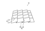
- FIG. 2 schematically shows a part of the composite material 10 in which the third fold line L3 and the fourth fold line L4 are formed.
- FIG. 2 is a perspective view schematically showing a part of the composite material 10 according to the present embodiment.
- the composite material 10 shown in FIG. 2 includes one layer of intermediate material (not shown), and the intermediate material includes folds corresponding to the third fold line L3 and the fourth fold line L4. That is, the first fold line L1 and the second fold line L2 are formed by folding only the skin material (not shown) of the composite material 10, and the third fold line L3 and the fourth fold line L4 are The composite material 10 is formed by folding the intermediate material together with the skin material.
- the acute angle ⁇ 34 (not shown) is approximately 0 °.
- first fold line L1 (further, the second fold line L2) and the third fold line L3, and the first fold line L1 (further, the second fold line L2) and the fourth fold line L4 are substantially orthogonal to each other. ( ⁇ 13 ⁇ 90 °).
- the arrangement of the folds is not limited to this.
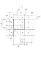
- FIG. 3 is a top view schematically showing a part of the composite material 10 shown in FIG. 2
- a region surrounded by two adjacent first folds L1 (L11, L12) and two adjacent third folds L3 (L31, L32) (
- four regions A to D having different apparent number of layers that is, cross-sectional thickness
- the size of the unit region R is determined by the arrangement of the folds, but is preferably a rectangle having a side of 1 to 20 cm from the viewpoint of design.
- the distance D 1 (see FIG. 1) is 1 to 20 cm
- the distance D 3 between the adjacent third folds L3 is 1 to 20 cm.
- the distance D 4 between the adjacent fourth folds L4 is preferably 1 to 20 cm.
- the distance D 34 (the width of the second fold P2) between the adjacent third fold line L3 and the fourth fold line L4 is preferably 0.5 to 5 cm.
- Area A includes a skin material, an intermediate material, and a backing material, one layer each in this order from the skin material side.
- the skin material is folded by the first fold line L1 and the second fold line L2. Therefore, the region B apparently includes a three-layer skin material, a one-layer intermediate material, and a one-layer backing material in this order from the skin material side.
- the region C apparently includes one layer of skin material, two layers of intermediate material, two layers of skin material, one layer of intermediate material, and one layer of backing material in this order from the skin material side.
- the skin material and the intermediate material are folded by the third fold line L3 and the fourth fold line L4.
- the region D apparently includes a three-layer skin material, a two-layer intermediate material, a six-layer skin material, a one-layer intermediate material, and a one-layer backing material in this order from the skin material side. That is, in the unit region R, the thickness of the composite material 10 increases in the order of the regions A to D. Thus, according to this embodiment, since the thickness of the composite material 10 changes in steps within a small region of 20 cm ⁇ 20 cm or less, the stereoscopic effect is enhanced.
- the thickness of the region with the smallest thickness is preferably 1 mm to 2.5 mm, more preferably 1 mm to 2 mm from the viewpoint of wear resistance.
- the thickness of the thickest region is preferably 3 mm to 10 mm, more preferably 4 mm to 8 mm, from the viewpoint of wear resistance and design properties. .
- the difference in thickness between the region with the smallest thickness and the region with the largest thickness is preferably 2 mm or more from the viewpoint of design properties, and is preferably 8 mm or less from the viewpoint of wear resistance.
- the difference in thickness between the steps is preferably 0.3 to 6.6 mm, and more preferably 0.5 to 2 mm.
- the thickness changes in two or more stages.
- the change in thickness is preferably about 4 steps. If the change in thickness is within this range, when the composite material 10 is installed in the vehicle, the non-uniformity of the bending resistance of the composite material 10 is hardly affected, and therefore workability is easily improved.
- the composite material includes, for example, a folding process for forming a plurality of first creases L1 and second creases L2 on the skin material, and a skin material on which the folds are formed via a first adhesive layer. And a backing layer laminating step of laminating the backing material.
- the method for forming the first crease L1 and the second crease L2 on the skin material is not particularly limited, and a conventionally known method can be used.
- the skin material is sandwiched between two patterns and then folded together. After removing the pattern, heat treatment is performed to fix the crease.
- the step of folding the skin material may be performed by hand folding (so-called hand folding), or may be performed by using a reciprocating type, rotary type, striping type or the like machine that forms the folds.
- the skin material Prior to the folding process, the skin material is subjected to a pre-treatment such as pre-setting and scouring, and a coloring process such as dyeing, if necessary.
- the folding process can be performed multiple times. Thereby, the third fold line L3 and the fourth fold line L4 as shown in FIG. 2 can be formed. For example, the direction of the skin material on which the first fold line L1 and the second fold line L2 are formed is changed, and the second folding is performed again using the same pattern. Alternatively, the second folding is performed on the skin material on which the first fold line L1 and the second fold line L2 are formed using another pattern.
- a backing is laminated on one main surface of a skin material on which a desired crease is formed via a first adhesive layer. Thereby, a composite material is obtained. After laminating the backing, it is preferable to press the composite while heating. Thereby, the crease is sharpened and the shape retention is further improved.
- the heating and pressing of the composite material can be performed using a conventionally known device. The conditions are not particularly limited, and may be set as appropriate according to the equipment used, the material of the composite material, and the like.
- the first adhesive layer is formed by laminating a film-like or nonwoven fabric-like first adhesive on a skin material or a backing material (or an intermediate material), or a solution-like first adhesive agent on a skin material or a backing material ( Or it is formed by heating after applying to an intermediate material.
- the 1st adhesive bond layer is formed with a nonwoven fabric-like 1st adhesive at the point which the shape retainability of a fold is easy to improve.
- the first adhesive layer is formed by melting a nonwoven fabric formed of a fibrous thermoplastic resin.
- an intermediate material Prior to the backing material lamination step, an intermediate material may be laminated on the skin material via a second adhesive layer.
- a folding process may be performed on the laminate of the skin material and the intermediate material.
- a fold corresponding to at least one of the first fold, the second fold, the third fold, and the fourth fold is formed in the intermediate material.
- the crease may be formed a plurality of times successively on the laminate of the skin material and the intermediate material.
- another intermediate material is further laminated on the intermediate material side via the second adhesive layer, and then the second and subsequent times. Folding may be performed.
- the M-th (M ⁇ 1) intermediate material is laminated on the skin material (or the laminate of the skin material and the intermediate material) on which the crease is formed. Thereafter, the (N + 1) th folding process may be performed. In this case, a complicated crease is formed and its shape retention is improved.
- the second adhesive layer is preferably formed of a non-woven second adhesive.
- the second adhesive layer is formed by melting a nonwoven fabric formed of a fibrous thermoplastic resin, like the first adhesive layer.
- Abrasion resistance It measured on condition of the following according to JIS L1096 8.19.3 C method (Theba type method). Five round test pieces having a diameter of 120 mm were collected from the composite material. The test conditions were a wear wheel CS-10, a load of 4.9 N, a friction frequency of 5000 times, and the skin material side was rubbed. The test piece after friction was observed and judged according to the following criteria. If the evaluation standard is grade 3 or higher, it can be said that the vehicle has sufficient wear resistance as a vehicle interior material application.
- the crease shape of the test piece before and after the abrasion resistance test was determined according to the following criteria.
- the shape of the crease of the test piece before the wear resistance test was evaluated as formability, and the shape of the fold of the test piece after the wear resistance test was evaluated as shape retention.
- Example 1 The following skin material was folded using a pattern and pressed while being heated to form a first fold and a second fold.
- a woven fabric having a mass W1: 250 g / m 2 (warp and weft: PET fiber having a fineness of 167 dtex / 48 filament, density: 180 warp / 25.4 mm, width 60 / 25.4 mm, thickness T1: 0 .7 mm, curve rate: 0.5%).
- the structure on the first surface of the skin material is a changed texture of oblique weaving, and after the warp is arranged on the first main surface side of three continuous wefts, the second main surface side of the two wefts And had a repeating pattern.
- the intermediate material was laminated. Thereafter, the obtained laminate was pressed while being heated at a temperature of 130 ° C.
- the intermediate material is a plain woven fabric (mass W3: 30 g / m 2 , warp and weft: 34 dtex PET fiber, density: 82 warps / 25.4 mm, width 48 / 25.4 mm, thickness T3: 0.35 mm) Was used.
- the resulting laminate was folded using another pattern. Subsequently, the pattern paper is removed, pressing is performed while heating at 130 ° C., and the laminate including the first fold line L1, the second fold line L2, the third fold line L3, and the fourth fold line L4 shown in FIG. Got.
- the acute angle ⁇ 1 , the acute angle ⁇ 2 , the acute angle ⁇ 12 , the acute angle ⁇ 3 , the acute angle ⁇ 4, and the acute angle ⁇ 34 were all about 0 °, and the angle ⁇ 13 was about 90 °.
- the distance D 1 is 5 cm
- the distance D 2 is 5 cm
- the distance D 12 is 1 cm
- the distance D 3 is 5 cm
- the distance D 4 is 5 cm
- the distance D 34 was 1 cm.
- Region A (thickness 1.5 mm), region B (thickness 2.4 mm), region C (thickness 5 mm), and region D (thickness 5.9 mm) shown in FIG. 2 were formed in the composite material.
- the following backing material was laminated on the intermediate material side of the laminated body via the first adhesive layer (adhesive A1).
- the obtained laminate was pressed while being heated at 170 ° C. to obtain a composite material for vehicle interior.
- the evaluation results are shown in Table 1.
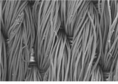
- photographed the composite material before an abrasion-resistance test from the skin material side is shown to FIG. 4A, and the photograph after a test is shown to FIG. 4B.
- the backing is a dobby woven fabric having a mass W2 of 190 g / m 2 (warp and weft: PET fibers having a fineness of 167 dtex / 48 filaments, density: 120 warp / 25.4 mm, width 70 / 25.4 mm, thickness T2: 0.45 mm) was used.
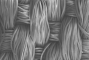
- Example 2 As the skin material, the texture on the first surface is a changed texture of oblique weaving, and after the warp is arranged on the first main surface side of the two wefts, it is arranged on the second main surface side of the three wefts A vehicle interior composite material was obtained in the same manner as in Example 1 using the same fabric as in Example 1 except that it had a repeating pattern. The evaluation results are shown in Table 1. Moreover, the photograph which image
- the texture on the first surface is a changed texture of oblique weaving, and after the warp is arranged on the first main surface side of the three wefts, it is arranged on the second main surface side of the two wefts And a pattern in which the warp is arranged on the second main surface side of one weft after the warp is arranged on the first main surface side of three wefts, and has a mass W1: 300 g / m 2
- a vehicle interior composite material was obtained in the same manner as in Example 1 except that was used.
- the above-mentioned woven fabric is warp and weft: 300 dtex / 72 filament PET fiber, density: 150 warp / 25.4 mm, width 50 / 25.4 mm, thickness T1: 1.0 mm, curve rate: 0.5% there were.
- the evaluation results are shown in Table 1.
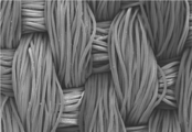
- photographed the composite material before an abrasion-resistance test from the skin material side is shown to FIG. 6A, and the photograph after a test is shown to FIG. 6B.
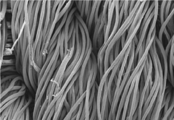
- Example 4 As a skin material, mass W1: 250 g / m 2 , warp and weft: 167 dtex / 144 filament PET fiber, density: 180 vertical / 25.4 mm, horizontal 60 / 25.4 mm, thickness T1: 0.7 mm A vehicle interior composite material was obtained in the same manner as in Example 1 using a fabric having the same structure as in Example 1 except that the turn rate was 0.5%. The evaluation results are shown in Table 1. Moreover, the photograph which image
- All the composite materials produced in Examples 1 to 4 are excellent in wear resistance, formability and shape retention.
- the composite material produced in Example 1 is rated as grade 4 even when the number of wear is 10,000, and is excellent in wear resistance.
- the composite material of the present invention is suitable as a vehicle interior material because it has excellent design and wear resistance.
Landscapes
- Engineering & Computer Science (AREA)
- Textile Engineering (AREA)
- Mechanical Engineering (AREA)
- Vehicle Interior And Exterior Ornaments, Soundproofing, And Insulation (AREA)
- Laminated Bodies (AREA)
Abstract
Description
表皮材は、それぞれ複数の第1の折り目および第2の折り目を備える。第1の折り目およびこれに隣接する第2の折り目により、表皮材には1つのヒダ(第1のヒダ)が形成される。
裏材は、表皮材に積層されて、表皮材に形成された第1の折り目および第2の折り目を固定して保持することにより、各折り目の形状保持性を向上させる。
表皮材と裏材とは、例えば、接着剤層(第1の接着剤層)を介して接着される。第1の接着剤層は、表皮材と裏材との間に介在し、裏材と表皮材とを、必要に応じて後述する中間材を介して、接着する。
表皮材と裏材との間には、1以上の中間材が配置されることが好ましい。中間材は、表皮材が備える折り目の少なくとも1つに対応する折り目を備えており、表皮材に形成された折り目を補強する機能を有する。
複合材が中間材を備える場合、表皮材と中間材、さらには、複数の中間材同士は、第2の接着剤層により接着される。このとき、上記の第1の接着剤層は、裏材と中間材とを接着する。この場合、表皮材と1以上の中間材とを第2の接着剤層を介して接着させた後、折り加工が施される。
本実施形態にかかる複合材は、車両内装材に適した高い耐磨耗性を有する。
例えば、複合材の表皮材側を、JIS L1096 8.19.3 C法(テーバ形法)に準じる方法で摩耗させると、表皮材の表面の状態に変化はないか、毛羽立ちが少し見られる程度である。
以下、複合材の製造方法について説明する。ただし、本実施形態の複合材の製造方法はこれに限定されない。
表皮材に第1の折り目L1および第2の折り目L2を形成する方法は特に限定されず、従来公知の方法を用いることができる。例えば、表皮材を2枚の型紙で挟んだ後、型紙とともに折りたたむ。型紙を取り去った後、熱処理を行って、折り目を固定する。表皮材を折りたたむ工程は、手折り(いわゆるハンド折り目)であってもよいし、レシプロ式、ロータリー式、ストライピング式等で折り目を形成するマシンを用いて行ってもよい。折り加工工程に先立って、表皮材には、必要に応じて、プレセット、精練等の前処理、染色等の加色工程が行われる。
所望の折り目が形成された表皮材の一方の主面に、第1の接着剤層を介して裏材を積層する。これにより、複合材が得られる。裏材を積層した後、複合材を加熱しながら押圧することが好ましい。これにより、折り目がシャープになるとともに、形状保持性がより向上する。複合材の加熱および押圧は、従来公知の機器を用いて行うことができる。その条件も特に限定されず、使用する機器や複合材の材質等に応じて適宜設定すればよい。
裏材積層工程の前に、表皮材に、第2の接着剤層を介して中間材を積層してもよい。
この場合、表皮材と中間材との積層体に対して、折り加工工程が行われてもよい。このとき、中間材には、第1の折り目、第2の折り目、第3の折り目および第4の折り目の少なくとも1つに対応する折り目が形成される。折り加工が複数回行われる場合、表皮材と中間材との積層体に対して、続けて複数回の折り目形成を施してもよい。また、表皮材と中間材との積層体に1回目の折り目形成を施した後、中間材側にさらに別の中間材を第2の接着剤層を介して積層し、その後、2回目以降の折り加工を行ってもよい。つまり、N回目(N≧1)の折り加工の後、折り目が形成された表皮材(あるいは、表皮材と中間材との積層体)にM枚目(M≧1)の中間材を積層し、その後、N+1回目の折り加工を行ってもよい。この場合、複雑な折り目が形成されるとともに、その形状保持性が向上する。
以下、実施例により本発明をさらに詳しく説明するが、本発明はこれら実施例に限定されるものではない。
(1)耐摩耗性
JIS L1096 8.19.3 C法(テーバ形法)に準じて、下記条件にて測定した。複合材から、直径120mmの円形の試験片を5枚採取した。試験条件は、摩耗輪CS-10、荷重4.9N、摩擦回数5000回として、表皮材側を摩擦した。摩擦後の試験片を観察し、下記の基準に従って判定した。評価基準が3級以上であれば、車両内装材用途として十分な耐摩耗性を有するといえる。
5級 : 表面の状態に変化がない
4級 : 繊維に少し毛羽立ちがみられる
3級 : 繊維に毛羽立ちがみられるものの、糸の状態に変化はない
2級 : 繊維に毛羽立ちがみられ、かつ、糸が細くなっている
1級 : 糸切れがある
上記耐摩耗試験前後の試験片の折り目の形状について、下記基準に従って判定した。耐摩耗試験の前の試験片の折り目の形状を賦型性として、耐摩耗試験の後の試験片の折り目の形状を形状保持性として評価した。
最良:折り目が全く丸みを帯びておらず、極めてシャープである
良 :折り目が丸みを帯びておらず、シャープである
不良:折り目に丸みが認められ、シャープさに欠ける
以下の表皮材を、型紙を用いて折りたたみ、加熱しながら押圧して、第1の折り目と第2の折り目とを形成した。
表皮材には、質量W1:250g/m2の織物(経糸および緯糸:繊度167dtex/48フィラメントのPET繊維、密度:タテ180本/25.4mm、ヨコ60本/25.4mm、厚みT1:0.7mm、目曲がり率:0.5%)を用いた。表皮材の第1表面における組織は、斜文織の変化組織であり、経糸が、連続する3本の緯糸の第1主面側に配置された後、2本の緯糸の第2主面側に配置される、繰り返しパターンを有していた。
中間材には、平織物(質量W3:30g/m2、経糸および緯糸:34dtexのPET繊維、密度:タテ82本/25.4mm、ヨコ48本/25.4mm、厚みT3:0.35mm)を用いた。
裏材には、質量W2:190g/m2のドビー織物(経糸および緯糸:繊度167dtex/48フィラメントのPET繊維、密度:タテ120本/25.4mm、ヨコ70本/25.4mm、厚みT2:0.45mm)を用いた。
表皮材として、第1表面における組織が斜文織の変化組織であり、経糸が2本の緯糸の第1主面側に配置された後、3本の緯糸の第2主面側に配置される、繰り返しパターンを有すること以外は実施例1と同様の織物を用いて、実施例1と同様にして車両内装用複合材を得た。評価結果を表1に示す。また、耐摩耗性試験前の複合材を表皮材側から撮影した写真を図5Aに示し、試験後の写真を図5Bに示す。
表皮材として、第1表面における組織が斜文織の変化組織であり、経糸が3本の緯糸の第1主面側に配置された後、2本の緯糸の第2主面側に配置されるパターンと、経糸が3本の緯糸の第1主面側に配置された後、1本の緯糸の第2主面側に配置されるパターンとを備え、質量W1:300g/m2の織物を用いたこと以外は、実施例1と同様にして、車両内装用複合材を得た。上記織物は、経糸および緯糸:300dtex/72フィラメントのPET繊維、密度:タテ150本/25.4mm、ヨコ50本/25.4mm、厚みT1:1.0mm、目曲がり率:0.5%であった。評価結果を表1に示す。また、耐摩耗性試験前の複合材を表皮材側から撮影した写真を図6Aに示し、試験後の写真を図6Bに示す。
表皮材として、質量W1:250g/m2であり、経糸および緯糸:167dtex/144フィラメントのPET繊維、密度:タテ180本/25.4mm、ヨコ60本/25.4mm、厚みT1:0.7mm、目曲がり率0.5%であること以外は実施例1と同様の組織を備える織物を用いて、実施例1と同様にして車両内装用複合材を得た。評価結果を表1に示す。また、耐摩耗性試験前の複合材を表皮材側から撮影した写真を図7Aに示し、試験後の写真を図7Bに示す。

L1、L11、L12:第1の折り目
L2:第2の折り目
L3、L31、L32:第3の折り目
L4:第4の折り目
P1:第1のヒダ
P2:第2のヒダ
Claims (7)
- 車両内装用の複合材であって、
前記複合材の一方の最外に配置され、第1主面と前記第1主面とは反対側の第2主面とを備える表皮材と、
前記複合材の他方の最外であって、前記表皮材の前記第2主面側に配置される裏材と、を備えており、
前記表皮材は、繊維構造体により形成されるとともに、前記表皮材の前記第1主面を外側にして折り返す複数の第1の折り目と、前記第1主面を内側にして折り返す複数の第2の折り目と、を備え、
隣接する前記第1の折り目同士が平行であるか、これらの成す鋭角θ1が10°以下であり、
隣接する前記第2の折り目同士が平行であるか、これらの成す鋭角θ2が10°以下であり、
隣接する前記第1の折り目と前記第2の折り目とが平行であるか、これらの成す鋭角θ12が10°以下である、車両内装用複合材。 - 前記表皮材は、さらに、前記表皮材の前記第1主面を外側にして折り返す複数の第3の折り目と、前記第1主面を内側にして折り返す複数の第4の折り目と、を備え、
隣接する前記第3の折り目と前記第4の折り目とが平行であるか、これらの成す鋭角θ34が10°以下であり、
前記第3の折り目および前記第4の折り目は、複数の前記第1の折り目と交差する、請求項1に記載の車両内装用複合材。 - 前記第1の折り目と前記第3の折り目との成す角度θ13が90°であるか、または、前記第1の折り目と前記第3の折り目との成す前記角度θ13のうち小さい方が、10°以上である、請求項2に記載の車両内装用複合材。
- さらに、前記表皮材と前記裏材との間に介在する1以上の中間材を備える、請求項2または3に記載の車両内装用複合材。
- 前記中間材は、前記表皮材の前記第1の折り目、前記第2の折り目、前記第3の折り目および前記第4の折り目の少なくとも1つに対応する折り目を備える、請求項4に記載の車両内装用複合材。
- 前記表皮材の前記第1主面に露出する繊維の繊度が、117~225dtexである、請求項1~5のいずれか一項に記載の車両内装用複合材。
- 前記表皮材は、第1の繊維および前記第1の繊維と交差する第2の繊維により形成される織物であり、
前記織物の前記第1主面の組織において、
前記第1の繊維が、連続する3本以上の前記第2の繊維の前記第1主面側に配置され、続いて、連続する2本以下の前記第2の繊維の前記第2主面側に配置されるパターンを有している、請求項1~6のいずれか一項に記載の車両内装用複合材。
Priority Applications (4)
| Application Number | Priority Date | Filing Date | Title |
|---|---|---|---|
| EP18813169.2A EP3636425A4 (en) | 2017-06-09 | 2018-06-04 | COMPOSITE FOR VEHICLE INTERIORS |
| JP2019523531A JP6746785B2 (ja) | 2017-06-09 | 2018-06-04 | 車両内装用複合材 |
| US16/616,836 US11192324B2 (en) | 2017-06-09 | 2018-06-04 | Composite material for vehicle interior |
| CN201880038049.2A CN110753612B (zh) | 2017-06-09 | 2018-06-04 | 车辆内部装饰用复合材 |
Applications Claiming Priority (2)
| Application Number | Priority Date | Filing Date | Title |
|---|---|---|---|
| JP2017-114664 | 2017-06-09 | ||
| JP2017114664 | 2017-06-09 |
Publications (1)
| Publication Number | Publication Date |
|---|---|
| WO2018225697A1 true WO2018225697A1 (ja) | 2018-12-13 |
Family
ID=64565848
Family Applications (1)
| Application Number | Title | Priority Date | Filing Date |
|---|---|---|---|
| PCT/JP2018/021416 Ceased WO2018225697A1 (ja) | 2017-06-09 | 2018-06-04 | 車両内装用複合材 |
Country Status (5)
| Country | Link |
|---|---|
| US (1) | US11192324B2 (ja) |
| EP (1) | EP3636425A4 (ja) |
| JP (1) | JP6746785B2 (ja) |
| CN (1) | CN110753612B (ja) |
| WO (1) | WO2018225697A1 (ja) |
Families Citing this family (2)
| Publication number | Priority date | Publication date | Assignee | Title |
|---|---|---|---|---|
| CN111717412B (zh) * | 2020-06-17 | 2022-05-06 | 江西洪都航空工业集团有限责任公司 | 一种柔性弹翼蒙皮变形载荷测试装置 |
| DE102022115728A1 (de) * | 2022-06-24 | 2024-01-04 | Bayerische Motoren Werke Aktiengesellschaft | Interieurteil für ein Fahrzeug, Verfahren zur Herstellung eines derartigen Interieurteils sowie Fahrzeug |
Citations (5)
| Publication number | Priority date | Publication date | Assignee | Title |
|---|---|---|---|---|
| JPS62104737A (ja) * | 1985-10-31 | 1987-05-15 | Toyota Motor Corp | 芯材と表皮材との接合方法 |
| JPH0350701B2 (ja) * | 1982-11-08 | 1991-08-02 | Showa Denko Kk | |
| JPH0442109A (ja) * | 1990-06-08 | 1992-02-12 | Olympus Optical Co Ltd | 不均質媒質を用いたレンズ系 |
| JPH0439083Y2 (ja) * | 1987-08-06 | 1992-09-11 | ||
| WO2017006556A1 (ja) | 2015-07-08 | 2017-01-12 | セーレン株式会社 | エンボス加工用複合材およびエンボス加工品 |
Family Cites Families (8)
| Publication number | Priority date | Publication date | Assignee | Title |
|---|---|---|---|---|
| JPH0442109Y2 (ja) | 1984-11-30 | 1992-10-05 | ||
| GB2173448B (en) * | 1985-12-30 | 1989-03-15 | Mcdonald George W | Folded sheet |
| JP2001150577A (ja) * | 1999-11-25 | 2001-06-05 | Japan Vilene Co Ltd | 成型内装材用フィルム、成型内装材用基材及び成型内装材 |
| JP2004217052A (ja) * | 2003-01-14 | 2004-08-05 | Toyoda Spinning & Weaving Co Ltd | 車両用内装材及び車両用内装材の製造方法 |
| US20040180177A1 (en) * | 2003-03-12 | 2004-09-16 | Ray Kyle A. | Thermoformable acoustic material |
| JP2005264408A (ja) * | 2004-03-22 | 2005-09-29 | Honda Motor Co Ltd | 車両用表皮材及びその製造方法、自動車用内装材及び自動二,三輪車用シート材 |
| JP5491232B2 (ja) | 2010-02-23 | 2014-05-14 | 株式会社林技術研究所 | 車両用成形敷設内装材 |
| CN105377626B (zh) * | 2013-07-05 | 2017-11-14 | 世联株式会社 | 汽车用合成皮革 |
-
2018
- 2018-06-04 US US16/616,836 patent/US11192324B2/en active Active
- 2018-06-04 WO PCT/JP2018/021416 patent/WO2018225697A1/ja not_active Ceased
- 2018-06-04 EP EP18813169.2A patent/EP3636425A4/en active Pending
- 2018-06-04 CN CN201880038049.2A patent/CN110753612B/zh active Active
- 2018-06-04 JP JP2019523531A patent/JP6746785B2/ja active Active
Patent Citations (5)
| Publication number | Priority date | Publication date | Assignee | Title |
|---|---|---|---|---|
| JPH0350701B2 (ja) * | 1982-11-08 | 1991-08-02 | Showa Denko Kk | |
| JPS62104737A (ja) * | 1985-10-31 | 1987-05-15 | Toyota Motor Corp | 芯材と表皮材との接合方法 |
| JPH0439083Y2 (ja) * | 1987-08-06 | 1992-09-11 | ||
| JPH0442109A (ja) * | 1990-06-08 | 1992-02-12 | Olympus Optical Co Ltd | 不均質媒質を用いたレンズ系 |
| WO2017006556A1 (ja) | 2015-07-08 | 2017-01-12 | セーレン株式会社 | エンボス加工用複合材およびエンボス加工品 |
Non-Patent Citations (1)
| Title |
|---|
| See also references of EP3636425A4 |
Also Published As
| Publication number | Publication date |
|---|---|
| EP3636425A1 (en) | 2020-04-15 |
| US20200324508A1 (en) | 2020-10-15 |
| CN110753612A (zh) | 2020-02-04 |
| EP3636425A4 (en) | 2021-01-20 |
| JP6746785B2 (ja) | 2020-08-26 |
| CN110753612B (zh) | 2021-09-21 |
| JPWO2018225697A1 (ja) | 2020-04-02 |
| US11192324B2 (en) | 2021-12-07 |
Similar Documents
| Publication | Publication Date | Title |
|---|---|---|
| KR102086892B1 (ko) | 스페이서 직물, 스페이서 직물로 형성된 복합 재료 및 복합 재료의 이용 | |
| CN111850801B (zh) | 复合组件 | |
| JP4111534B2 (ja) | 人工皮革及びそれに用いる基体、並びにそれらの製造方法 | |
| JP4708494B2 (ja) | 繊維積層シートとこれを用いた人工皮革及びこれに用いる合成繊維紙 | |
| CN105377626A (zh) | 汽车用合成皮革 | |
| JP6942138B2 (ja) | 低通気度及び高強度の布地ならびにその製造方法 | |
| KR20130138772A (ko) | 부직포용 다층직물 | |
| US8669194B2 (en) | Airbag | |
| JP6746785B2 (ja) | 車両内装用複合材 | |
| US20110070791A1 (en) | Wonder Fabric | |
| JP6972564B2 (ja) | シート状物 | |
| JP2016191163A (ja) | 衣類 | |
| JP3187096U (ja) | 縫製品 | |
| US8778818B2 (en) | Anti-vandalism fabric suitable for upholstering seats | |
| JP6539495B2 (ja) | 積層体布帛 | |
| JP4385199B2 (ja) | 人造皮革と車両椅子張地 | |
| JP2022038822A (ja) | 繊維シート及び該繊維シートを用いた人工皮革の製造方法 | |
| CN219564391U (zh) | 多层纤维纺织布及片状擦拭布 | |
| JP5034968B2 (ja) | 接着芯地 | |
| JPH07166476A (ja) | 低通気性織物及びその製造方法 | |
| JP7549856B2 (ja) | スリップ抑制パイル織物、及び、その製造方法 | |
| JP6965033B2 (ja) | 車両内装用複合材 | |
| JP7420697B2 (ja) | 車両内装材向けスエード調表皮材 | |
| JP6709059B2 (ja) | 広幅且つ伸びを有する人工皮革 | |
| JP2005089873A (ja) | 撚糸モール糸を使用した車輛座席用布帛 |
Legal Events
| Date | Code | Title | Description |
|---|---|---|---|
| 121 | Ep: the epo has been informed by wipo that ep was designated in this application |
Ref document number: 18813169 Country of ref document: EP Kind code of ref document: A1 |
|
| ENP | Entry into the national phase |
Ref document number: 2019523531 Country of ref document: JP Kind code of ref document: A |
|
| NENP | Non-entry into the national phase |
Ref country code: DE |
|
| WWE | Wipo information: entry into national phase |
Ref document number: 2018813169 Country of ref document: EP |
|
| ENP | Entry into the national phase |
Ref document number: 2018813169 Country of ref document: EP Effective date: 20200109 |