WO2019012725A1 - Dispositif, système et procédé de conversion de puissance - Google Patents
Dispositif, système et procédé de conversion de puissance Download PDFInfo
- Publication number
- WO2019012725A1 WO2019012725A1 PCT/JP2018/005405 JP2018005405W WO2019012725A1 WO 2019012725 A1 WO2019012725 A1 WO 2019012725A1 JP 2018005405 W JP2018005405 W JP 2018005405W WO 2019012725 A1 WO2019012725 A1 WO 2019012725A1
- Authority
- WO
- WIPO (PCT)
- Prior art keywords
- power conversion
- power
- unit
- voltage
- conversion unit
- Prior art date
- Legal status (The legal status is an assumption and is not a legal conclusion. Google has not performed a legal analysis and makes no representation as to the accuracy of the status listed.)
- Ceased
Links
Images





Classifications
-
- H—ELECTRICITY
- H02—GENERATION; CONVERSION OR DISTRIBUTION OF ELECTRIC POWER
- H02M—APPARATUS FOR CONVERSION BETWEEN AC AND AC, BETWEEN AC AND DC, OR BETWEEN DC AND DC, AND FOR USE WITH MAINS OR SIMILAR POWER SUPPLY SYSTEMS; CONVERSION OF DC OR AC INPUT POWER INTO SURGE OUTPUT POWER; CONTROL OR REGULATION THEREOF
- H02M3/00—Conversion of DC power input into DC power output
- H02M3/02—Conversion of DC power input into DC power output without intermediate conversion into AC
- H02M3/04—Conversion of DC power input into DC power output without intermediate conversion into AC by static converters
- H02M3/10—Conversion of DC power input into DC power output without intermediate conversion into AC by static converters using discharge tubes with control electrode or semiconductor devices with control electrode
- H02M3/145—Conversion of DC power input into DC power output without intermediate conversion into AC by static converters using discharge tubes with control electrode or semiconductor devices with control electrode using devices of a triode or transistor type requiring continuous application of a control signal
- H02M3/155—Conversion of DC power input into DC power output without intermediate conversion into AC by static converters using discharge tubes with control electrode or semiconductor devices with control electrode using devices of a triode or transistor type requiring continuous application of a control signal using semiconductor devices only
- H02M3/156—Conversion of DC power input into DC power output without intermediate conversion into AC by static converters using discharge tubes with control electrode or semiconductor devices with control electrode using devices of a triode or transistor type requiring continuous application of a control signal using semiconductor devices only with automatic control of output voltage or current, e.g. switching regulators
- H02M3/158—Conversion of DC power input into DC power output without intermediate conversion into AC by static converters using discharge tubes with control electrode or semiconductor devices with control electrode using devices of a triode or transistor type requiring continuous application of a control signal using semiconductor devices only with automatic control of output voltage or current, e.g. switching regulators including plural semiconductor devices as final control devices for a single load
- H02M3/1584—Conversion of DC power input into DC power output without intermediate conversion into AC by static converters using discharge tubes with control electrode or semiconductor devices with control electrode using devices of a triode or transistor type requiring continuous application of a control signal using semiconductor devices only with automatic control of output voltage or current, e.g. switching regulators including plural semiconductor devices as final control devices for a single load with a plurality of power processing stages connected in parallel
-
- H—ELECTRICITY
- H02—GENERATION; CONVERSION OR DISTRIBUTION OF ELECTRIC POWER
- H02M—APPARATUS FOR CONVERSION BETWEEN AC AND AC, BETWEEN AC AND DC, OR BETWEEN DC AND DC, AND FOR USE WITH MAINS OR SIMILAR POWER SUPPLY SYSTEMS; CONVERSION OF DC OR AC INPUT POWER INTO SURGE OUTPUT POWER; CONTROL OR REGULATION THEREOF
- H02M3/00—Conversion of DC power input into DC power output
- H02M3/02—Conversion of DC power input into DC power output without intermediate conversion into AC
- H02M3/04—Conversion of DC power input into DC power output without intermediate conversion into AC by static converters
- H02M3/10—Conversion of DC power input into DC power output without intermediate conversion into AC by static converters using discharge tubes with control electrode or semiconductor devices with control electrode
- H02M3/145—Conversion of DC power input into DC power output without intermediate conversion into AC by static converters using discharge tubes with control electrode or semiconductor devices with control electrode using devices of a triode or transistor type requiring continuous application of a control signal
- H02M3/155—Conversion of DC power input into DC power output without intermediate conversion into AC by static converters using discharge tubes with control electrode or semiconductor devices with control electrode using devices of a triode or transistor type requiring continuous application of a control signal using semiconductor devices only
- H02M3/156—Conversion of DC power input into DC power output without intermediate conversion into AC by static converters using discharge tubes with control electrode or semiconductor devices with control electrode using devices of a triode or transistor type requiring continuous application of a control signal using semiconductor devices only with automatic control of output voltage or current, e.g. switching regulators
-
- H—ELECTRICITY
- H02—GENERATION; CONVERSION OR DISTRIBUTION OF ELECTRIC POWER
- H02J—ELECTRIC POWER NETWORKS; CIRCUIT ARRANGEMENTS OR SYSTEMS FOR SUPPLYING OR DISTRIBUTING ELECTRIC POWER; SYSTEMS FOR STORING ELECTRIC ENERGY
- H02J1/00—Circuit arrangements for DC mains or DC distribution networks
- H02J1/10—Parallel operation of DC sources
- H02J1/102—Parallel operation of DC sources being switching converters
-
- H—ELECTRICITY
- H02—GENERATION; CONVERSION OR DISTRIBUTION OF ELECTRIC POWER
- H02J—ELECTRIC POWER NETWORKS; CIRCUIT ARRANGEMENTS OR SYSTEMS FOR SUPPLYING OR DISTRIBUTING ELECTRIC POWER; SYSTEMS FOR STORING ELECTRIC ENERGY
- H02J7/00—Circuit arrangements for charging or discharging batteries or for supplying loads from batteries
- H02J7/855—Circuit arrangements for charging or discharging batteries or for supplying loads from batteries with circuits adapted for supplying loads from the battery
-
- H—ELECTRICITY
- H02—GENERATION; CONVERSION OR DISTRIBUTION OF ELECTRIC POWER
- H02M—APPARATUS FOR CONVERSION BETWEEN AC AND AC, BETWEEN AC AND DC, OR BETWEEN DC AND DC, AND FOR USE WITH MAINS OR SIMILAR POWER SUPPLY SYSTEMS; CONVERSION OF DC OR AC INPUT POWER INTO SURGE OUTPUT POWER; CONTROL OR REGULATION THEREOF
- H02M7/00—Conversion of AC power input into DC power output; Conversion of DC power input into AC power output
- H02M7/02—Conversion of AC power input into DC power output without possibility of reversal
- H02M7/04—Conversion of AC power input into DC power output without possibility of reversal by static converters
- H02M7/06—Conversion of AC power input into DC power output without possibility of reversal by static converters using discharge tubes without control electrode or semiconductor devices without control electrode
- H02M7/08—Conversion of AC power input into DC power output without possibility of reversal by static converters using discharge tubes without control electrode or semiconductor devices without control electrode arranged for operation in parallel
-
- H—ELECTRICITY
- H02—GENERATION; CONVERSION OR DISTRIBUTION OF ELECTRIC POWER
- H02M—APPARATUS FOR CONVERSION BETWEEN AC AND AC, BETWEEN AC AND DC, OR BETWEEN DC AND DC, AND FOR USE WITH MAINS OR SIMILAR POWER SUPPLY SYSTEMS; CONVERSION OF DC OR AC INPUT POWER INTO SURGE OUTPUT POWER; CONTROL OR REGULATION THEREOF
- H02M7/00—Conversion of AC power input into DC power output; Conversion of DC power input into AC power output
- H02M7/02—Conversion of AC power input into DC power output without possibility of reversal
- H02M7/04—Conversion of AC power input into DC power output without possibility of reversal by static converters
- H02M7/12—Conversion of AC power input into DC power output without possibility of reversal by static converters using discharge tubes with control electrode or semiconductor devices with control electrode
- H02M7/21—Conversion of AC power input into DC power output without possibility of reversal by static converters using discharge tubes with control electrode or semiconductor devices with control electrode using devices of a triode or transistor type requiring continuous application of a control signal
- H02M7/217—Conversion of AC power input into DC power output without possibility of reversal by static converters using discharge tubes with control electrode or semiconductor devices with control electrode using devices of a triode or transistor type requiring continuous application of a control signal using semiconductor devices only
- H02M7/219—Conversion of AC power input into DC power output without possibility of reversal by static converters using discharge tubes with control electrode or semiconductor devices with control electrode using devices of a triode or transistor type requiring continuous application of a control signal using semiconductor devices only in a bridge configuration
-
- H—ELECTRICITY
- H02—GENERATION; CONVERSION OR DISTRIBUTION OF ELECTRIC POWER
- H02J—ELECTRIC POWER NETWORKS; CIRCUIT ARRANGEMENTS OR SYSTEMS FOR SUPPLYING OR DISTRIBUTING ELECTRIC POWER; SYSTEMS FOR STORING ELECTRIC ENERGY
- H02J2207/00—Details of circuit arrangements for charging or discharging batteries or supplying loads from batteries
- H02J2207/20—Charging or discharging characterised by the power electronics converter
-
- H—ELECTRICITY
- H02—GENERATION; CONVERSION OR DISTRIBUTION OF ELECTRIC POWER
- H02M—APPARATUS FOR CONVERSION BETWEEN AC AND AC, BETWEEN AC AND DC, OR BETWEEN DC AND DC, AND FOR USE WITH MAINS OR SIMILAR POWER SUPPLY SYSTEMS; CONVERSION OF DC OR AC INPUT POWER INTO SURGE OUTPUT POWER; CONTROL OR REGULATION THEREOF
- H02M3/00—Conversion of DC power input into DC power output
- H02M3/02—Conversion of DC power input into DC power output without intermediate conversion into AC
- H02M3/04—Conversion of DC power input into DC power output without intermediate conversion into AC by static converters
- H02M3/10—Conversion of DC power input into DC power output without intermediate conversion into AC by static converters using discharge tubes with control electrode or semiconductor devices with control electrode
- H02M3/145—Conversion of DC power input into DC power output without intermediate conversion into AC by static converters using discharge tubes with control electrode or semiconductor devices with control electrode using devices of a triode or transistor type requiring continuous application of a control signal
- H02M3/155—Conversion of DC power input into DC power output without intermediate conversion into AC by static converters using discharge tubes with control electrode or semiconductor devices with control electrode using devices of a triode or transistor type requiring continuous application of a control signal using semiconductor devices only
- H02M3/156—Conversion of DC power input into DC power output without intermediate conversion into AC by static converters using discharge tubes with control electrode or semiconductor devices with control electrode using devices of a triode or transistor type requiring continuous application of a control signal using semiconductor devices only with automatic control of output voltage or current, e.g. switching regulators
- H02M3/158—Conversion of DC power input into DC power output without intermediate conversion into AC by static converters using discharge tubes with control electrode or semiconductor devices with control electrode using devices of a triode or transistor type requiring continuous application of a control signal using semiconductor devices only with automatic control of output voltage or current, e.g. switching regulators including plural semiconductor devices as final control devices for a single load
Definitions
- the present application relates to a power converter of a configuration in which power conversion units are multiplexed in parallel.
- the parallel multiplexing configuration of the power conversion unit is attracting attention as a design relaxation technique that does not require custom design according to the required specifications.
- it is necessary to have a function of averaging power to avoid concentration of power on a specific power conversion unit (for example, Patent Document 1).
- An object of the present invention is to provide a power conversion device capable of determining whether it is an isolated operation without using it.
- the power conversion device disclosed in the present application is a power converter for converting power between a power supply and a load, the load side being a direct current, and for controlling the load side voltage of this power converter to a target voltage
- a plurality of power conversion units each having a voltage controller provided with a voltage adjustment unit that performs proportional control by inputting a steady-state deviation that is the difference between the target voltage and the voltage on the load side;
- at least one power conversion unit of the plurality of power conversion units includes an operation management unit that manages the operation of its own power conversion unit, and the operation management unit By changing the proportional gain of the proportional control of the voltage regulator and comparing the change of the proportional gain and the change of the steady state deviation, the other power conversion units other than the own power conversion unit are operating. It is obtained so as to determine whether the isolated operation are.
- only one power conversion unit among a plurality of power conversion units whose output terminals are connected in parallel does not use information from the outside of its own power conversion unit. , It can be determined whether the power conversion unit of its own is an isolated operation.
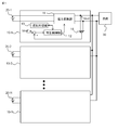
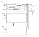
- FIG. 1 is a block diagram showing a configuration of a power conversion system including a power conversion device according to a first embodiment.
- FIG. 1 is a block diagram showing a configuration of a power conversion system including another power conversion device according to Embodiment 1. It is a circuit diagram which shows the example of a detailed structure of the power conversion unit of FIG. It is a circuit diagram which shows the example of a detailed structure of the power conversion unit of FIG.
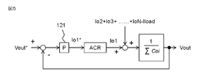
- FIG. 5 is a diagram showing a control block schematically illustrating a control system of a power conversion unit of the power conversion device according to the first embodiment.
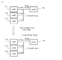
- FIG. 6 is a schematic diagram for explaining the operation of the power conversion device according to the first embodiment when the power conversion unit is operating alone.
- FIG. 1 is a block diagram showing a configuration of a power conversion system including a power conversion device according to a first embodiment.
- FIG. 1 is a block diagram showing a configuration of a power conversion system including another power conversion device according to Embodiment 1. It is a circuit diagram which shows
- FIG. 7 is a schematic diagram for explaining the operation of the power conversion device according to Embodiment 1 when the power conversion units are operating in parallel.
- FIG. 16 is a schematic diagram illustrating another operation of the power conversion device according to Embodiment 1 when power conversion units are operating in parallel.
- 5 is a flowchart for explaining the operation of the power conversion device according to the first embodiment.
- FIG. 10 is a flowchart for illustrating the operation of the power conversion device according to the second embodiment.
- FIG. 7 is a diagram showing characteristics of a specific example of the power conversion device according to the second embodiment.
- FIG. 13 is a diagram for illustrating the effect of the power conversion device according to the second embodiment.
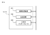
- FIG. 10 is a block diagram showing a configuration of a power conversion system including a power conversion device according to a third embodiment. It is a block diagram which shows an example of the hardware constitutions of the voltage controller of a power converter device, and operation management part.
- FIG. 1 is a block diagram showing a configuration of a power conversion system including the power conversion device according to the first embodiment.
- the power conversion apparatus includes N power conversion units 10-1, 10-2, ..., 10-N (typically, one power conversion unit may be described as the power conversion unit 10), and each of them is shown.
- the output of the power converter 11 provided in the power conversion unit is configured to supply power to the same load 30.
- Power conversion units 10-1, 10-2,..., 10-N in FIG. 1 receive direct current from direct current power supplies 20-1, 20-2,.
- the DC bus voltage) Vout is configured to be output. That is, the power converter 11 of each power conversion unit is a DC / DC converter.
- FIG. 2 is a block diagram showing a configuration of a power conversion system including another power conversion device according to the first embodiment.
- the power conversion device includes N power conversion units 10-1, 10-2, ..., 10-N (one power conversion unit may be described as a power conversion unit 10), and the respective power conversions are performed.
- the output of the power converter 11 provided in the unit is configured to supply power to the same load 30.
- Power conversion units 10-1, 10-2,..., 10-N shown in FIG. 2 receive AC power supplies 21-1, 21-2, ..., 21-N, respectively, and output DC voltage (DC bus voltage) ) Is configured to output Vout. That is, the power converter 11 of each power conversion unit is an AC / DC converter.
- the operation management unit 13 also controls the DC bus voltage Vout, which is the voltage on the load side detected by the voltage sensor 15, to the target voltage Vout *. And the operation management unit 13 that changes the set value of the voltage controller 12 using the steady-state deviation (Vout * ⁇ Vout) between the target voltage Vout * and the DC bus voltage Vout.
- the operation management unit 13 also has a function of determining whether the power conversion unit is an isolated operation based on the setting value of the voltage controller 12 and the steady state deviation.
- the voltage controller 12 and the operation management unit 13 are a processing unit 101 such as a central processing unit (CPU) and a storage unit 102 for exchanging data with the processing unit 101. And an input / output interface 103 for inputting and outputting signals between the arithmetic processing unit 101 and the outside.
- the arithmetic processing unit 101 may include an application specific integrated circuit (ASIC), an integrated circuit (IC), a digital signal processor (DSP), a field programmable gate array (FPGA), various signal processing circuits, and the like.
- the voltage controller 12 and the operation management unit 13 may be configured by one arithmetic processing unit 101.
- the storage device 102 includes a random access memory (RAM) configured to be able to read and write data from the arithmetic processing unit 101, a read only memory (ROM) configured to be able to read data from the arithmetic processing unit 101, and the like. It is done.
- the input / output interface 103 includes, for example, an A / D converter for inputting a signal output from the voltage sensor 15 to the arithmetic processing unit 101, a drive circuit for outputting a signal to the power converter 11, and the like.
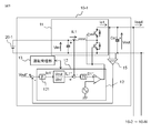
- FIG. 3 is a block diagram showing a specific example of power converter 11 and voltage controller 12 in FIG. 1
- FIG. 4 is a block diagram showing a specific example of power converter 11 and voltage controller 12 in FIG.
- the power converter 11 of one power conversion unit is a DC / DC converter
- the power converter 11 of another power conversion unit is an AC / DC converter. It is also good.
- the power supply on the input side in each power conversion unit may be common or separate, or the power supply on the input side in some power conversion units may be common or any configuration .
- the number N of power conversion units in parallel may be any number.
- the load is not limited to a simple resistive load.
- FIG. 5 shows a control block schematically illustrating the control system of the power conversion unit in the configuration of FIGS. 3 and 4.
- FIG. 5 means that the control system including the current control system is simplified. Handle the ACR gain described as 1.
- the current control system in FIGS. 2 and 3 included in the configuration expressed as ACR in simplified form in FIG. 5 receives the target value Io1 * of the DC bus current from the voltage adjustment unit 121 and calculates the target value Io1 * of the DC bus current.
- the duty D1 of the power conversion unit is controlled so that the target value IL1 * of the input current obtained by converting the ratio of the input voltage Vin1 of the power conversion unit and the DC bus voltage Vout matches the detection current IL1.
- the power converter disclosed in the present application can be realized when the voltage controller 12 that controls the DC bus voltage Vout to the target voltage Vout * has a drooping characteristic in the DC bus voltage according to the output power.
- the configuration of the voltage adjustment unit 121 in the voltage controller 12 is not limited to the P control (proportional control) 121 shown in FIGS. 3 and 4.
- the voltage adjustment unit 121 receives a steady state deviation that is the difference between the target voltage Vout * and the actual voltage Vout, and inputs the steady state deviation itself, or a square of the steady state deviation, or a half power of the steady state deviation.
- the control system may be any control system that performs proportional control so that the steady state deviation approaches zero, by multiplying the value based on the steady state deviation by the proportional gain regardless of non-linearity.
- the operation of the operation management unit 13 of the first embodiment will be described.
- the simplified control block diagram shown in FIG. 5 will be used in the description of the first embodiment.
- the voltage adjustment unit 121 in FIG. 5 has a control configuration having a characteristic that the steady-state deviation (Vout * -Vout) of the target voltage Vout * and the DC bus voltage Vout changes in accordance with the input power or output power of the power conversion unit. It is replaceable. Further, the configuration of the voltage adjustment unit 121 and the like are not limited.
- the voltage adjustment unit 121 performs P control in which proportional control is performed on the steady-state deviation (Vout * ⁇ Vout) itself will be described as an example.
- Vout * ⁇ Vout the relationship between the DC bus current Ioi output from the power conversion unit accompanying the change in proportional gain of the voltage adjustment unit 121 and the steady-state deviation of the target value Vout * of the DC bus voltage and the actual voltage Vout will be described.
- the relationship between the target value Vout * of the DC bus voltage and the actual voltage Vout shown in FIG. 5 can be expressed by equation (1).
- K is a proportional gain
- Co is the capacity of the output capacitor Co provided on the output side of each power conversion unit
- Coi means the capacity of the output capacitor of the ith power conversion unit 10-i.
- the denominator on the right side and the zero-order term of the s-function of the numerator are set as the constant ⁇ K because they are common.
- the effects of voltage controllers of other power conversion units are considered. If the proportional gains of all the power conversion units are common, the equations (1), (2) and (3) can be replaced by the equations (4), (5) and (6).
- the denominator on the right side and the zero-order term of the s-function of the numerator are common, they are set as the constant ⁇ K0 .
- the load that can be applied as the load of the power conversion device disclosed in the present application may be a load that can be simulated on a constant resistance load or a constant power load on time average, even if it is a nonlinear load that causes instantaneous power change, It is not limited to a constant resistance load or a constant power load without time fluctuation.
- the load may include a power generation function.
- the load will be described as a load that can be time-averaged and simulated as a constant resistance load or a constant power load. Therefore, the load will be described as a constant resistance load or a constant power load.
- the power conversion unit can estimate the load by using the target value Io1 * of the DC bus current generated by the voltage adjustment unit 121 in the voltage controller 12 of its own and the detected value Vout of the DC bus voltage. That is, by assuming that the target value Io1 * of the DC bus current generated by the voltage adjustment unit 121 is the load current, if the load can be simulated as a constant resistance load, the resistance value can be estimated or can be simulated as a constant power load Can estimate the power.
- the equation (9) is an estimation equation of the estimated resistance value Rx in the case of the constant resistance load
- the equation (10) is an estimation equation of the estimated power value Px in the case of the constant power load.
- FIG. 6 is a view schematically showing the operation of the power conversion unit at the time of single operation
- FIG. 7 schematically shows the operation of the power conversion unit at the time of three units connected in parallel.
- Equations (15) and (16) become equations for estimating resistance in the case of constant resistance load in steady state corresponding to equations (11) and (13) during islanding operation, respectively.
- the power estimation equations in the case of a constant power load are as shown in equations (17) and (18), respectively.
- the proportional gain changes by ⁇ K before and after, in the case of a load that can simulate a constant resistance load, the estimated resistance value of the constant resistance load is estimated, and in the case of a load that can simulate a constant power load, the power estimation of a constant power load It can be seen that the values take the same value.
- equations for estimating the constant power load are as shown in equations (21) and (22).
- the estimated value of the constant resistance load or the constant power load takes different values before and after the proportional gain changes by ⁇ K in parallel operation of three units.
- the quotient of steady-state deviation and DC bus voltage (Vout * -Vout) / Vout is obtained for a constant resistance load with respect to the change ratio (K ⁇ K) / K of proportional gain.
- the product of steady-state deviation and DC bus voltage (Vout * ⁇ Vout) ⁇ Vout changes by K / (K ⁇ K) times, which is the reciprocal of the change ratio of the proportional gain.
- the estimated values of the load obtained by the equations (9) and (10) become the same value.
- the ratio of change in proportional gain (K ⁇ K) / K in the case of constant resistance load, the quotient of steady-state deviation and DC bus voltage (Vout * ⁇ Vout) / Vout, constant power load
- the product of the steady state deviation and the DC bus voltage (Vout * ⁇ Vout) ⁇ Vout changes at a change ratio different from K / (K ⁇ K) times, which is the reciprocal of the change ratio of the proportional gain.
- estimated values of the load obtained by the equations (9) and (10) take different values.
- ⁇ K is a half value of the original proportional gain
- the estimated value of equation (19) is three-fifth smaller than the estimated value of equation (20)
- the estimated value of equation (21) is 5 times larger than the estimated value of the equation).
- the DC bus voltage Vout of the power conversion unit and Io1 * that is the output of the voltage adjustment unit 121 use the resistance estimated value Rx according to equation (9) in the case of a constant resistance load, and (10) in the case of a constant power load
- the power estimated value Px By determining the power estimated value Px by the equation, it is possible to determine whether it is an isolated operation or a parallel operation.
- comparing the change in proportional gain with the change in resistance estimated value in the case of a constant resistance load means that the change in proportional gain is compared with the change in (Vout * -Vout) / Vout.
- comparing the change of the proportional gain with the change of the power estimated value in the case of the constant power load means comparing the change of the proportional gain with the change of (Vout * ⁇ Vout) ⁇ Vout.
- the rate of change of Vout is smaller than the rate of change of steady-state deviation (Vout * ⁇ Vout) due to the change of proportional gain. Therefore, comparing the change of the proportional gain with the change of the estimated value of the load substitutes the comparison of the change of the proportional gain with the change of the steady state deviation (Vout * ⁇ Vout).
- the equations (23), (24) and (25) correspond to the equations (1), (2) and (3), respectively, and correspond to configurations in which the proportional gain of the voltage adjustment unit 121 of each power conversion unit is different. It is a formula.
- the denominator of the right side of the equation (23) and the zero-order term of the s function of the numerator are common, they are set as the constant ⁇ KN .
- FIG. 6 schematically showing the operation of the power conversion unit at the time of single operation
- FIG. 8 schematically showing the operation of the power conversion unit at the time of parallel operation of three units.
- the equation (26) represents a relationship corresponding to the equation (6) at the time of sole operation
- the equation (27) represents a relationship corresponding to the equation (6) at the time of three-unit parallel operation.
- the estimation formula of the constant power load is as shown in equations (32) and (33). That is, it can be seen that the estimated value of the constant resistance load or the constant power load takes the same value before and after the proportional gain is changed by ⁇ K at the time of isolated operation.
- the voltage adjustment unit of one power conversion unit is used in parallel operation as in the case where the proportional gains are common. It can be seen that the constant resistance load or the estimated value of the constant power load takes different values before and after the change of the proportional gain 121 by ⁇ K.
- the proportional gain is changed, and the resistance estimated value or the power estimated value of the load is obtained before and after the change of the proportional gain, and the change of the proportional gain is compared with the change of the estimated value of the load. It is understood that it can be judged whether it is driving or parallel driving. Comparing the change in proportional gain with the change in estimated load value, as described above, substitutes the comparison between the change in proportional gain and the change in steady state deviation, and the change in proportional gain and the steady state deviation By comparison with the change of, it is judged whether it is an isolated operation or a parallel operation.
- FIG. 9 is a flowchart for realizing the isolated operation determination, and shows the operation of the operation management unit 13.
- the process start timing of the flowchart shown in FIG. 9 can be arbitrarily set.
- load is estimated using equation (9) or (10), that is, using DC bus voltage Vout and target value Io1 * of the current which is the output of voltage adjustment unit 121 (step ST1).
- Store the estimated value step ST2).
- step ST1 in the case of a load that can be simulated to a constant resistance load, the resistance estimation value Rx of a constant resistance load can be simulated according to the characteristics of the load; In the case where the estimated value Px can be simulated to either a constant resistance load or a constant power load, at least one may be obtained.
- the proportional gain of the voltage adjustment unit 121 is changed (step ST3), and the load is estimated (step ST4). After changing the proportional gain, take the difference between the previous estimated value and the current estimated value (step ST5), and if the change is smaller than the preset value (step ST5 Yes), add the count (step ST6). If the change is larger than the above value, the count is reset (step ST7).
- step ST9 When the count is added, when the count reaches the number of determinations (Yes in step ST8), it is determined that the single operation is performed (step ST9). If it is determined to be an isolated operation, the process ends.
- step ST7 When the count is reset (ST7), or when the count has not reached the number of determinations (No at step ST8), when the number of times of gain change has not reached the preset upper limit (No at step ST10), step ST2 Return to and store the estimate. Thereafter, the steps from step ST3 for changing the gain are executed. In this manner, the gain change is repeated until it is determined as an isolated operation (step ST9) or until the number of gain changes reaches the upper limit (Yes in step ST10) and it is determined that parallel operation is performed (step ST11).
- the gain is changed by ⁇ K from the original gain setting value K at the first time, that is, the gain is set to K ⁇ K.
- the second time returns the gain, which was K- ⁇ K, to K.
- the gain is again set to K- ⁇ K.
- the gain is repeatedly changed between K and K- ⁇ K.
- the reason for determining the isolated operation when the difference absolute value between the current estimated value and the previous estimated value is small and the count value by multiple gain changes has reached the number of determinations is transient fluctuation or other power conversion This is to prevent a determination error in isolated operation due to overlapping of processing timings by units.
- start timing of the process may be any timing, it is preferable to determine the cycle and process. For example, an individual number is assigned to each power conversion unit, processing start timings are periodically determined in the order of individual numbers, and processing periods of the power conversion units are different from each other to overlap processing timings between the power conversion units. Can be prevented.
- the power conversion operation of the other power conversion unit in which the other power conversion units are not connected in parallel or is connected in parallel By comparing the change in gain and the change in steady-state deviation when the gain is changed by the power conversion unit alone without obtaining information from other power conversion units during isolated operation in which the unit is stopped. It can be determined that it is an isolated operation.
- the power conversion unit may have a configuration having the operation management unit 13.
- Second Embodiment using the determination method of the single operation described in the first embodiment, it is proposed to improve the efficiency of the power conversion device that operates a plurality of power conversion units in parallel.
- the entire system of the power conversion device according to the second embodiment is the same as the configuration shown in FIGS. 1 to 4.
- the configuration and operation of the operation management unit 13 according to the second embodiment include configurations and operations added to improve the efficiency with respect to the configuration and operation of the operation management unit 13 according to the first embodiment.
- the process start timing of the flowchart shown in FIG. 10 can be set arbitrarily. After the processing starts, load estimation is performed using equation (9) or (10) (step ST21), and when the estimated value of power falls below the set power threshold (step ST22 Yes), the estimated value is stored Then, the proportional gain of the voltage adjustment unit 121 is changed (step ST24), and when the estimated value of the power is equal to or exceeds the set power threshold (step ST22 No), the process ends.
- the power threshold can be set for each power conversion unit, and for example, a power threshold that does not fall below any efficiency is set.
- step ST25 After changing the proportional gain of voltage adjustment section 121, the load is estimated (step ST25), the difference between the previous estimated value and the current estimated value is taken, and if the change is larger than the preset value (step ST26 Yes) Are added (step ST27), and when the change is smaller than the preset value (step ST26 No), the count is reset (step ST28).
- step ST30 When the count is added, when the count reaches the number of determinations (Yes in step ST29), it is determined that parallel operation is performed (step ST30), and the power conversion operation of the power conversion unit is paused (step ST31).
- step ST28 If the count has been reset (step ST28) or if the count has not reached the number of determinations (step ST29 No), if the number of gain changes has not reached the preset upper limit (step ST32 No), the step Returning to ST23, the estimated value is stored.
- the change of the gain is repeated until the power conversion operation is suspended by determining the parallel operation (step ST31) or until the number of times of change of the gain reaches the upper limit.
- the change of the gain is repeated by changing the gain with K and K- ⁇ K as described in the first embodiment.
- the determination of parallel operation in the second embodiment is in the relationship between the determination of an isolated operation in the first embodiment and logic inversion.
- the pause of the power conversion operation means the state of the output power 0 of the power conversion unit including the proportional gain 0.
- step ST21 in the load estimation in step ST21 immediately after the start of the process, it is necessary to perform power estimation of at least a constant power load.
- step ST25 at least one of load estimation of constant resistance load and load estimation of constant power load may be performed according to the characteristics of the load.
- step ST25 when only the load estimation of the constant resistance load is performed in step ST25, it is necessary to perform the load estimation of the constant resistance load also in step ST21.
- step ST26 when the difference absolute value between the current estimated value and the previous estimated value is large (step ST26), and the count value due to multiple gain changes reaches the number of determinations (step ST29 Yes)
- step ST30 The reason for performing the operation and the determination (step ST30) is to prevent a parallel operation detection error due to a transient fluctuation or overlapping of processing timing by another power conversion unit.
- the DC bus voltage may decrease if the load power can not be covered.
- the DC bus voltage can be restored to the reference value Vout * 1 or more by stopping the processing and changing the proportional gain to a large value such as the original value.
- the process start timing may be any timing, but it is preferable to determine the cycle and process. For example, an individual number is assigned to each power conversion unit, and processing start timings are periodically determined in order of individual number so that the processing period of each power conversion unit is different, thereby processing timing between consecutive power conversion units. Overlap can be prevented.
- FIG. 12 is an example of the efficiency improvement operation in the system of the power conversion device composed of two power conversion units, power conversion unit A and power conversion unit B having the efficiency characteristics shown in FIG.
- the proportional gain of the voltage adjustment unit 121 of the power conversion unit A and the power conversion unit B is common, and the proportional gain change is to alternately change 1.0 times and 0.5 times the design value. Do.
- the output power of the power conversion unit A increases and the output power of the power conversion unit B decreases. Based on the power change due to this proportional gain change, it is determined as parallel operation as described above, and the operation of power conversion unit B is stopped, and as shown by the lower graph in FIG. Do.
- the operating point of the power conversion unit A at this time is a point of an output 1100 W indicated by a black circle.
- the input at this time is 1183 W, and the efficiency is 93.0%.
- the efficiency of the power conversion device as a whole can be improved to 93.0% after the pause, compared to 88.9% before the pause of the power conversion unit B.
- the second embodiment it is detected whether or not the other power conversion unit is performing the power conversion operation at the time of operation below the power threshold, and the other power conversion unit performs the power conversion operation. It is possible to improve the efficiency of the power conversion unit group as a whole by stopping operation when it is done.
- a load including a power generation mechanism such as solar power generation, wind power generation, or hydro power generation using the method of improving the efficiency of the power conversion device operating in parallel a plurality of power conversion units described in the second embodiment. The corresponding efficiency improvement will be described.
- FIG. 13 is a block diagram showing an example of a power conversion system including the power conversion device according to the third embodiment.
- the load 30 includes a power generation mechanism 32 such as solar power generation, wind power generation, or hydro power generation, in addition to the power consumption load 31 that consumes power.
- the power conversion unit in the power conversion device according to the third embodiment is the same as the configuration and operation of the power conversion device shown in FIGS. 1 to 12.
- the configuration and operation of the power conversion unit according to the third embodiment will be described below with reference to FIGS. 1 to 12 and FIG. 13 in which the load 30 shown in FIGS. 1 and 2 is replaced with a form corresponding to the third embodiment.
- the description of the operation of the power conversion unit according to the third embodiment omits the description overlapping with that of the second embodiment, and only differences from the configuration difference of the load 30 will be described.
- a load 30 shown in FIG. 13 is configured to include a power consumption load 31 and a power generation mechanism 32.
- the load current Iload takes a positive value when the power consumption of the power consumption load 31 is larger than the generated power of the power generation mechanism 32, and a negative value when the power consumption of the power consumption load 31 is smaller than the generated power of the power generation mechanism 32. take.
- the load current is positive
- the power converter operates to convert power from the power source to the load.
- the load current is negative
- the power converter 11 operates to convert the power from the load side to the power source side. That is, the power converter 11 connected between the power supply and the load can convert power from the power supply side to the load side or can convert power from the load side to the power supply side. Act as.
- the load current Iload When the load current Iload is negative, power is supplied from the load 30 to the power conversion unit, which means that the actual voltage Vout becomes larger than the target voltage Vout *, as shown by the equations (9) and (10).
- the estimated resistance value Rx and the estimated power value Px take negative values.
- the power conversion unit to which power is supplied returns the power to the power supply side, for example, performs an operation of charging the storage battery connected to the power supply side. Since the efficiency improvement method shown in the second embodiment determines parallel operation based on the change absolute value of the estimated values Rx and Px before and after the proportional gain change (FIG. 10, step ST26), the configuration of the third embodiment Is equally applicable.
- the load current Iload When the load current Iload is negative, the power generated by the power generation mechanism 32 of the load increases after shutdown, and power can not be stored by charging only the power conversion units other than the shutdown. Can be considered. In this case, the DC bus voltage is further increased. Therefore, when the DC bus voltage exceeds the predetermined reference value Vout * 2 as a value higher than the target voltage Vout *, the power conversion operation of the power conversion unit suspended of operation is resumed and restored to the operating state again.
- the DC bus voltage is higher than the target voltage Vout * only when the load includes a power generation mechanism, so there is no need to monitor the direction of the load current, and it is possible to monitor the DC bus voltage. Just do it.
- the DC bus voltage may rise above the reference value Vout * 2 if the generated power of the load can not be stored. is there.
- the DC bus voltage can be restored to the reference value Vout * 2 or less by stopping the processing and changing the proportional gain to a large value such as the original value. That is, the reference value Vout * 1 for canceling the operation suspension at the time of overload shown in the second embodiment is set lower than the target voltage of the voltage controller 12, and the operation suspension at the over power generation shown in the embodiment 3 is performed.
- the DC bus voltage can always be kept between the reference value Vout * 1 and the reference value Vout * 2, and bidirectional power can be obtained. It is possible to realize stable operation corresponding to transfer.
Landscapes
- Engineering & Computer Science (AREA)
- Power Engineering (AREA)
- Dc-Dc Converters (AREA)
- Rectifiers (AREA)
Abstract
Selon une configuration dans laquelle plusieurs unités de conversion de puissance équipées chacune d'un convertisseur de puissance servant à effectuer une conversion de puissance entre une alimentation électrique et une charge sont multiplexées en parallèle, au moins l'une des unités de conversion de puissance est pourvue d'une unité de gestion de fonctionnement (13) servant à gérer le fonctionnement du convertisseur de puissance (11). L'unité de gestion de fonctionnement (13) modifie le gain proportionnel d'une unité de régulation de tension (121) dans laquelle est entrée une déviation stable qui est la différence entre une tension cible et une tension côté charge pour effectuer une commande proportionnelle, et compare une variation du gain proportionnel à une variation de l'écart constant, ce qui permet de déterminer si le fonctionnement est un fonctionnement autonome dans lequel aucune unité de conversion de puissance autre que l'unité de conversion de puissance pertinente ne fonctionne.
Priority Applications (3)
| Application Number | Priority Date | Filing Date | Title |
|---|---|---|---|
| US16/612,641 US10848065B2 (en) | 2017-07-13 | 2018-02-16 | Power conversion device, power conversion system, and power conversion device operation method |
| JP2019529440A JP6727440B2 (ja) | 2017-07-13 | 2018-02-16 | 電力変換装置、電力変換システム、および電力変換装置の運転方法 |
| CN201880040307.0A CN110832762B (zh) | 2017-07-13 | 2018-02-16 | 电力变换装置、电力变换系统以及电力变换装置的运转方法 |
Applications Claiming Priority (2)
| Application Number | Priority Date | Filing Date | Title |
|---|---|---|---|
| JP2017-136991 | 2017-07-13 | ||
| JP2017136991 | 2017-07-13 |
Publications (1)
| Publication Number | Publication Date |
|---|---|
| WO2019012725A1 true WO2019012725A1 (fr) | 2019-01-17 |
Family
ID=65002282
Family Applications (1)
| Application Number | Title | Priority Date | Filing Date |
|---|---|---|---|
| PCT/JP2018/005405 Ceased WO2019012725A1 (fr) | 2017-07-13 | 2018-02-16 | Dispositif, système et procédé de conversion de puissance |
Country Status (4)
| Country | Link |
|---|---|
| US (1) | US10848065B2 (fr) |
| JP (1) | JP6727440B2 (fr) |
| CN (1) | CN110832762B (fr) |
| WO (1) | WO2019012725A1 (fr) |
Cited By (3)
| Publication number | Priority date | Publication date | Assignee | Title |
|---|---|---|---|---|
| WO2021234923A1 (fr) * | 2020-05-21 | 2021-11-25 | 東芝三菱電機産業システム株式会社 | Dispositif de conversion de puissance électrique, dispositif de commande de conversion de puissance électrique et procédé de commande |
| WO2023063073A1 (fr) * | 2021-10-14 | 2023-04-20 | オムロン株式会社 | Convertisseur de courant et système d'alimentation électrique de courant continu |
| JP2024052050A (ja) * | 2022-09-30 | 2024-04-11 | トヨタ自動車株式会社 | 電源システム |
Families Citing this family (3)
| Publication number | Priority date | Publication date | Assignee | Title |
|---|---|---|---|---|
| US10951021B2 (en) * | 2018-11-22 | 2021-03-16 | Mitsubishi Electric Corporation | Power conversion system |
| CN113746170B (zh) * | 2021-09-03 | 2024-02-09 | 阳光电源(上海)有限公司 | 一种储能系统及其离网过载保护方法 |
| US20250239856A1 (en) * | 2021-10-21 | 2025-07-24 | Mitsubishi Electric Corporation | Power conversion system |
Citations (3)
| Publication number | Priority date | Publication date | Assignee | Title |
|---|---|---|---|---|
| JPH06121534A (ja) * | 1992-10-01 | 1994-04-28 | Sansha Electric Mfg Co Ltd | 直流電源装置の並列運転装置 |
| JPH0956067A (ja) * | 1995-06-09 | 1997-02-25 | Mitsubishi Electric Corp | 整流器制御装置 |
| JP2010011567A (ja) * | 2008-06-25 | 2010-01-14 | Shindengen Electric Mfg Co Ltd | 電源装置及び電源装置の制御方法 |
Family Cites Families (12)
| Publication number | Priority date | Publication date | Assignee | Title |
|---|---|---|---|---|
| JPH1094260A (ja) * | 1996-09-12 | 1998-04-10 | Toyo Electric Mfg Co Ltd | インバータ装置の並列接続装置 |
| JP3028205B2 (ja) * | 1996-09-18 | 2000-04-04 | オムロン株式会社 | 分散型電源システムおよびパワーコンディショナ |
| CN1305199C (zh) * | 2000-09-29 | 2007-03-14 | 山洋电气株式会社 | 无停电电源装置、变换装置以及并联工作型变换装置 |
| JP4353114B2 (ja) * | 2005-03-14 | 2009-10-28 | オムロン株式会社 | パワーコンディショナ |
| JP5721828B2 (ja) * | 2011-06-22 | 2015-05-20 | 川崎重工業株式会社 | 異種発電装置間の並列運転制御方法および制御システム |
| JP5803681B2 (ja) * | 2012-01-12 | 2015-11-04 | 株式会社明電舎 | Pwm電力変換器の並列運転装置 |
| CA2895270A1 (fr) * | 2012-12-21 | 2014-06-26 | Daiichi Techno Co., Ltd. | Procede de commande et systeme de commande pour un fonctionnement en parallele entre differents types de generateur d'electricite |
| TWI548190B (zh) * | 2013-08-12 | 2016-09-01 | 中心微電子德累斯頓股份公司 | 根據控制法則來控制功率轉換器的功率級之控制器及方法 |
| JP6124262B2 (ja) | 2014-02-04 | 2017-05-10 | 三菱電機株式会社 | 電源装置 |
| JP6354503B2 (ja) | 2014-09-30 | 2018-07-11 | 株式会社デンソー | 電力変換システム |
| US20160248324A1 (en) * | 2015-02-20 | 2016-08-25 | Zentrum Mikroelektronik Dresden Ag | Pulse translation modulation for power converters |
| JP6678774B2 (ja) * | 2017-01-11 | 2020-04-08 | 東芝三菱電機産業システム株式会社 | 電力変換装置 |
-
2018
- 2018-02-16 WO PCT/JP2018/005405 patent/WO2019012725A1/fr not_active Ceased
- 2018-02-16 JP JP2019529440A patent/JP6727440B2/ja active Active
- 2018-02-16 US US16/612,641 patent/US10848065B2/en active Active
- 2018-02-16 CN CN201880040307.0A patent/CN110832762B/zh active Active
Patent Citations (3)
| Publication number | Priority date | Publication date | Assignee | Title |
|---|---|---|---|---|
| JPH06121534A (ja) * | 1992-10-01 | 1994-04-28 | Sansha Electric Mfg Co Ltd | 直流電源装置の並列運転装置 |
| JPH0956067A (ja) * | 1995-06-09 | 1997-02-25 | Mitsubishi Electric Corp | 整流器制御装置 |
| JP2010011567A (ja) * | 2008-06-25 | 2010-01-14 | Shindengen Electric Mfg Co Ltd | 電源装置及び電源装置の制御方法 |
Cited By (9)
| Publication number | Priority date | Publication date | Assignee | Title |
|---|---|---|---|---|
| WO2021234923A1 (fr) * | 2020-05-21 | 2021-11-25 | 東芝三菱電機産業システム株式会社 | Dispositif de conversion de puissance électrique, dispositif de commande de conversion de puissance électrique et procédé de commande |
| JP6980134B1 (ja) * | 2020-05-21 | 2021-12-15 | 東芝三菱電機産業システム株式会社 | 電力変換装置、電力変換制御装置、及び制御方法 |
| CN114026779A (zh) * | 2020-05-21 | 2022-02-08 | 东芝三菱电机产业系统株式会社 | 电力转换装置、电力转换控制装置及控制方法 |
| US12218604B2 (en) | 2020-05-21 | 2025-02-04 | Tmeic Corporation | Power converter, power conversion controller, and control method |
| WO2023063073A1 (fr) * | 2021-10-14 | 2023-04-20 | オムロン株式会社 | Convertisseur de courant et système d'alimentation électrique de courant continu |
| JP2023059105A (ja) * | 2021-10-14 | 2023-04-26 | オムロン株式会社 | 電力変換装置及び直流電力供給システム |
| JP7815678B2 (ja) | 2021-10-14 | 2026-02-18 | オムロン株式会社 | 直流電力供給システム |
| JP2024052050A (ja) * | 2022-09-30 | 2024-04-11 | トヨタ自動車株式会社 | 電源システム |
| JP7622718B2 (ja) | 2022-09-30 | 2025-01-28 | トヨタ自動車株式会社 | 電源システム |
Also Published As
| Publication number | Publication date |
|---|---|
| CN110832762A (zh) | 2020-02-21 |
| US10848065B2 (en) | 2020-11-24 |
| JPWO2019012725A1 (ja) | 2020-02-27 |
| JP6727440B2 (ja) | 2020-07-22 |
| US20200099305A1 (en) | 2020-03-26 |
| CN110832762B (zh) | 2021-06-15 |
Similar Documents
| Publication | Publication Date | Title |
|---|---|---|
| WO2019012725A1 (fr) | Dispositif, système et procédé de conversion de puissance | |
| CN109196762B (zh) | 电源系统 | |
| CN103493323B (zh) | 中间总线架构电力系统中的动态总线电压控制 | |
| US10164452B2 (en) | Battery pack and method for controlling discharge of secondary cell | |
| JP6247039B2 (ja) | 電力貯蔵装置および電力貯蔵装置の充放電方法 | |
| US10355492B2 (en) | Rechargeable battery controller | |
| JP6174154B2 (ja) | 蓄電池管理装置、方法及びプログラム | |
| JPWO2013140894A1 (ja) | 調整装置、組電池装置および調整方法 | |
| JP2015136202A (ja) | チョッパ回路 | |
| US10840729B2 (en) | Method and system for operating a DC-DC converter of an electrical system to distribute a load | |
| RU2427070C1 (ru) | Электромеханическое устройство | |
| US20230016507A1 (en) | Computer-readable recording medium storing control program and control method | |
| CN107949966B (zh) | 电源装置 | |
| CN118971160B (zh) | 发电系统的控制方法、装置和发电系统 | |
| WO2017195484A1 (fr) | Dispositif d'alimentation électrique et procédé d'alimentation électrique | |
| JP6453581B2 (ja) | 電力供給機器、電力供給システム、および電力供給方法 | |
| WO2017042973A1 (fr) | Système de batterie de stockage, procédé et programme | |
| CN116154944B (zh) | 供电系统、服务器节点及计算设备 | |
| JP2006149115A (ja) | 無停電電源システムの制御方法 | |
| JP2008253087A (ja) | サーボアンプおよびその診断装置 | |
| JP2018074847A (ja) | パワーコンディショナ | |
| CN119689328A (zh) | 储能模块开路检测方法、装置及功率变换设备 | |
| WO2023210123A1 (fr) | Unité de batterie et système d'alimentation électrique | |
| JP2017011901A (ja) | 太陽光発電システムの制御装置、太陽光発電システム、及び制御プログラム | |
| HK1252944B (zh) | 电源装置 |
Legal Events
| Date | Code | Title | Description |
|---|---|---|---|
| 121 | Ep: the epo has been informed by wipo that ep was designated in this application |
Ref document number: 18832582 Country of ref document: EP Kind code of ref document: A1 |
|
| ENP | Entry into the national phase |
Ref document number: 2019529440 Country of ref document: JP Kind code of ref document: A |
|
| NENP | Non-entry into the national phase |
Ref country code: DE |
|
| 122 | Ep: pct application non-entry in european phase |
Ref document number: 18832582 Country of ref document: EP Kind code of ref document: A1 |