WO2019012809A1 - Connecteur - Google Patents
Connecteur Download PDFInfo
- Publication number
- WO2019012809A1 WO2019012809A1 PCT/JP2018/019534 JP2018019534W WO2019012809A1 WO 2019012809 A1 WO2019012809 A1 WO 2019012809A1 JP 2018019534 W JP2018019534 W JP 2018019534W WO 2019012809 A1 WO2019012809 A1 WO 2019012809A1
- Authority
- WO
- WIPO (PCT)
- Prior art keywords
- connector
- stopper
- locked
- rear direction
- socket
- Prior art date
- Legal status (The legal status is an assumption and is not a legal conclusion. Google has not performed a legal analysis and makes no representation as to the accuracy of the status listed.)
- Ceased
Links
Images











Classifications
-
- H—ELECTRICITY
- H01—ELECTRIC ELEMENTS
- H01R—ELECTRICALLY-CONDUCTIVE CONNECTIONS; STRUCTURAL ASSOCIATIONS OF A PLURALITY OF MUTUALLY-INSULATED ELECTRICAL CONNECTING ELEMENTS; COUPLING DEVICES; CURRENT COLLECTORS
- H01R13/00—Details of coupling devices of the kinds covered by groups H01R12/70 or H01R24/00 - H01R33/00
- H01R13/40—Securing contact members in or to a base or case; Insulating of contact members
- H01R13/42—Securing in a demountable manner
- H01R13/424—Securing in base or case composed of a plurality of insulating parts having at least one resilient insulating part
-
- H—ELECTRICITY
- H01—ELECTRIC ELEMENTS
- H01R—ELECTRICALLY-CONDUCTIVE CONNECTIONS; STRUCTURAL ASSOCIATIONS OF A PLURALITY OF MUTUALLY-INSULATED ELECTRICAL CONNECTING ELEMENTS; COUPLING DEVICES; CURRENT COLLECTORS
- H01R13/00—Details of coupling devices of the kinds covered by groups H01R12/70 or H01R24/00 - H01R33/00
- H01R13/46—Bases; Cases
- H01R13/502—Bases; Cases composed of different pieces
- H01R13/508—Bases; Cases composed of different pieces assembled by a separate clip or spring
-
- H—ELECTRICITY
- H01—ELECTRIC ELEMENTS
- H01R—ELECTRICALLY-CONDUCTIVE CONNECTIONS; STRUCTURAL ASSOCIATIONS OF A PLURALITY OF MUTUALLY-INSULATED ELECTRICAL CONNECTING ELEMENTS; COUPLING DEVICES; CURRENT COLLECTORS
- H01R13/00—Details of coupling devices of the kinds covered by groups H01R12/70 or H01R24/00 - H01R33/00
- H01R13/40—Securing contact members in or to a base or case; Insulating of contact members
- H01R13/42—Securing in a demountable manner
- H01R13/422—Securing in resilient one-piece base or case, e.g. by friction; One-piece base or case formed with resilient locking means
-
- H—ELECTRICITY
- H01—ELECTRIC ELEMENTS
- H01R—ELECTRICALLY-CONDUCTIVE CONNECTIONS; STRUCTURAL ASSOCIATIONS OF A PLURALITY OF MUTUALLY-INSULATED ELECTRICAL CONNECTING ELEMENTS; COUPLING DEVICES; CURRENT COLLECTORS
- H01R13/00—Details of coupling devices of the kinds covered by groups H01R12/70 or H01R24/00 - H01R33/00
- H01R13/46—Bases; Cases
- H01R13/502—Bases; Cases composed of different pieces
- H01R13/506—Bases; Cases composed of different pieces assembled by snap action of the parts
-
- H—ELECTRICITY
- H01—ELECTRIC ELEMENTS
- H01R—ELECTRICALLY-CONDUCTIVE CONNECTIONS; STRUCTURAL ASSOCIATIONS OF A PLURALITY OF MUTUALLY-INSULATED ELECTRICAL CONNECTING ELEMENTS; COUPLING DEVICES; CURRENT COLLECTORS
- H01R13/00—Details of coupling devices of the kinds covered by groups H01R12/70 or H01R24/00 - H01R33/00
- H01R13/62—Means for facilitating engagement or disengagement of coupling parts or for holding them in engagement
- H01R13/639—Additional means for holding or locking coupling parts together, after engagement, e.g. separate keylock, retainer strap
Definitions
- the present invention relates to a connector, and more particularly to a connector comprising a contact removably mounted on an insulator.
- the connector 90 of Patent Document 1 includes a plurality of contacts 92 attached to the cable 98, and an insulator 94 attached to the contacts 92.
- the insulator 94 has a housing 940, a plurality of lock rings 944, a pressing block 948, and a locking release member 950.
- the housing 940 is formed with a plurality of cavities 942 that respectively receive the contacts 92 (see FIG. 33).
- lock rings 944 are respectively disposed within cavities 942.
- the pressure block 948 is fixed to the rear of the housing 940 so that the lock ring 944 is fixed in the cavity 942 of the housing 940.
- the unlocking member 950 is attached to the housing 940 via the pressing block 948.
- the unlocking member 950 is movable relative to the pressing block 948, ie, the housing 940, in the front-rear direction.
- Patent Document 1 does not clarify the configuration of the mating connector. However, when estimated from the shape of the connector 90, a relatively large gap exists between the tip of the mating contact and the mating insulator that holds the mating contact. This means that the mating connector does not have an electric shock preventing structure for preventing a person's finger from touching the mating contact. That is, the connector of Patent Document 1 is not considered at all for the connection with the mating connector provided with the electric shock prevention structure and the electric shock prevention structure of itself.
- the connector 90 of Patent Document 1 in order to remove the contact 92 from the insulator 94, the unlocking member 950 must be moved in the direction (forward) opposite to the direction (rear) of removing the contact 92. Therefore, the connector 90 of Patent Document 1 has a problem that the removal operation of the contact 92 is difficult. This problem is particularly noticeable when the insulator 94 is attached to the panel of the device.
- An object of the present invention is to provide a connector which can more easily remove a contact (terminal) attached to an insulator from the insulator.
- One aspect of the present invention is a connector attached to a cable, wherein It has multiple terminals, multiple stoppers, and a socket insulator, Each of the terminals has a cylindrical portion and a cable attachment portion, The cable attachment portion is a portion attached to the cable, and is positioned rearward of the cylindrical portion in the front-rear direction, The stoppers are respectively attached to the terminals, Each of the stoppers is provided with a locked portion and a lock spring portion, The locked portion is supported by the lock spring portion, The lock spring portion is elastically deformable.
- the socket insulator is formed with a plurality of housing portions, a plurality of lock portions, and a plurality of operation portions.
- the housing portion extends in the front-rear direction,
- the stopper is accommodated in the accommodating portion together with the terminal,
- the front end portion of the housing portion is open, and is located forward of the cylindrical portion in the front-rear direction,
- the lock portion is located rearward of the locked portion in a state in which the stopper is accommodated in the accommodation portion, and restricts the rearward movement of the stopper.
- the operation portion is operable in a predetermined direction intersecting the front-rear direction, and when operated, the locked portion is moved along the predetermined direction so that the lock portion is regulated by the lock portion. Provide a connector to release.
- the operating portion can be operated in a predetermined direction intersecting the front-rear direction. Thereby, the terminal can be more easily removed from the socket insulator.
- FIG. 5 is a perspective view of a connector assembly according to an embodiment of the present invention with a portion of a panel.
- the connector is fixed to the panel.
- the connector and the mating connector are each connected to a cable.
- the connector and the mating connector are not yet fitted.
- FIG. 7 is another perspective view of the connector assembly of FIG. 1 with a portion of the panel.
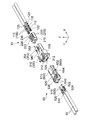
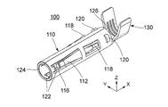
- the connector and the mating connector are engaged with each other. It is a disassembled perspective view which shows the connector assembly of FIG. It is a perspective view which shows the socket contact contained in the connector which comprises the connector assembly of FIG. It is another perspective view which shows the socket contact of FIG. It is a side view which shows the socket contact of FIG. It is a front view which shows the socket contact of FIG.
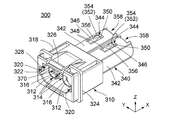
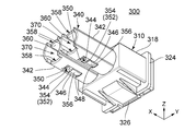
- FIG. 9 is a perspective sectional view showing the stopper of FIG. 8; It is a perspective view which shows the socket insulator contained in the connector which comprises the connector assembly of FIG. It is another perspective view which shows the socket insulator of FIG. It is a side view which shows the socket insulator of FIG. It is a front view which shows the socket insulator of FIG. It is a rear view which shows the socket insulator of FIG. It is a perspective cross-sectional view which shows the socket insulator of FIG.
- FIG. 19 is another perspective view showing the pin contact of FIG. 18; It is a side view which shows the pin contact of FIG. It is a perspective view which shows the pin insulator contained in the other party connector which comprises the connector assembly of FIG. It is another perspective view which shows the pin insulator of FIG. It is a top view which shows the pin insulator of FIG. FIG. 22 is a perspective sectional view showing the pin insulator of FIG. 21.
- FIG. 7 is a side view showing the socket contact of FIG. 6 attached to a cable.
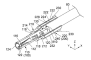
- FIG. 26 is a partial cross-sectional perspective view showing the stopper of FIG. 11 attached to the socket contact of FIG. 25; FIG.
- FIG. 21 is a side view showing the pin contact of FIG. 20 attached to a cable.
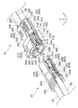
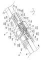
- FIG. 2 is a partial cross-sectional perspective view showing the connector assembly of FIG. 1;
- FIG. 3 is a partial cross-sectional perspective view of the connector assembly of FIG. 2;
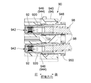
- FIG. 29 is a partial longitudinal cross-sectional view showing the connector included in the connector assembly of FIG. 28 together with a panel.
- a side view of the socket contact, a longitudinal sectional view of the stopper and a longitudinal sectional view of the socket insulator are included.
- FIG. 29 is a partial vertical cross-sectional view showing a mating connector included in the connector assembly of FIG. 28.
- a side view of the pin contact and a longitudinal sectional view of the pin insulator are included.
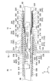
- FIG. 30 is a partial longitudinal sectional view showing the connector assembly of FIG. 29.
- a side view of the socket contact and the pin contact, and a longitudinal sectional view of the socket insulator, the stopper, the pin insulator and the panel are included.
- the connector 10 and the mating connector 50 are attached to the ends of two cables 80 respectively.
- the present invention is not limited to this.
- the connector 10 and the mating connector 50 may be attached to the end of one multicore cable.
- the connector 10 and the mating connector 50 can be fitted and separated from each other along the front-rear direction (fitting direction).
- the connector 10 and the mating connector 50 are fitted to each other to constitute a connector assembly.
- the front-rear direction is the X direction.
- the -X direction is the front, and the + X direction is the rear.
- the connector 10 includes a plurality of socket contacts (terminals) 100, a plurality of stoppers 200, and a socket insulator 300.
- the mating connector 50 includes a plurality of pin contacts 500 and a pin insulator 600.
- the number of socket contacts 100, the number of stoppers 200, and the number of pin contacts 500 are two.
- the connector 10 may comprise three or more socket contacts 100.
- the connector 10 comprises a number of stops 200 equal to the number of socket contacts 100.
- the mating connector 50 comprises a number of pin contacts 500 equal to the number of socket contacts 100.
- the socket contact 100 has a cylindrical portion 110 and a cable attachment portion 130 continuing to the cylindrical portion 110.
- the cylindrical portion 110 extends in the front-rear direction.
- the cylindrical portion 110 defines a radial direction orthogonal to the front-rear direction.
- the cylindrical portion 110 is located forward of the cable attachment portion 130 in the front-rear direction.
- the cable attachment portion 130 is located rearward of the cylindrical portion 110 in the front-rear direction.
- the cylindrical portion 110 is a portion that receives part of the pin contact 500 (see FIG. 29 or 32) when the connector 10 and the mating connector 50 are fitted.
- the cable attachment portion 130 is a portion attached to the cable 80 (see FIG. 3).
- the cable attachment portion 130 is a portion crimped to the core wire 810 of the cable 80 as shown in FIG.
- the cable attachment portion 130 may be attached to the core wire 810 of the cable 80 by a method other than crimping, for example, by soldering.
- the socket contact 100 is formed by punching and bending a single metal plate.
- the cylindrical portion 110 is provided with a plurality of contact support portions 112, a plurality of locking springs 118, a plurality of locking projections 120, and a plurality of guide portions 122.
- the contact support portions 112 are arranged at equal intervals in the circumferential direction of the cylindrical portion 110. The same applies to the locking spring 118, the locking projection 120, and the guide portion 122.
- the guide portion 122, the contact support portion 112, the locking spring 118 and the locking projection 120 are arranged in this order in the front-rear direction.
- the number of contact support portions 112, the number of locking springs 118, the number of locking projections 120, and the number of guide portions 122 are three. However, the present invention is not limited to this. At least one of the contact support portion 112, the locking spring 118, the locking projection 120, and the guide portion 122 may be provided.
- the contact support portion 112 is formed in a cantilever shape. Specifically, the contact support portion 112 obliquely extends forward from the central portion of the cylindrical portion 110 in the front-rear direction, and protrudes inward from the cylindrical portion 110 in the radial direction of the cylindrical portion 110.
- the contact support portion 112 supports the contact point 114 (see FIG. 7) and is elastically deformable. That is, the contact support portion 112 movably supports the contact point 114 at least in the radial direction of the cylindrical portion 110.
- the contact point 114 is formed as a part of the contact point support portion 112.
- the locking spring 118 is formed in a cantilever shape. Specifically, the locking spring 118 obliquely extends rearward from the central portion of the cylindrical portion 110 in the front-rear direction, and protrudes outward from the cylindrical portion 110 in the radial direction of the cylindrical portion 110.
- the locking spring 118 is elastically deformable. The length in the front-rear direction of the locking spring 118 is shorter than the length in the front-rear direction of the contact support portion 112.
- the locking projection 120 is located rearward of the locking spring 118 and away from the locking spring 118 in the front-rear direction.
- the locking projection 120 is located near the rear end 126 of the cylindrical portion 110.
- the cable attachment portion 130 subsequent to the rear end 126 of the cylindrical portion 110 is located rearward of the locking projection 120 in the front-rear direction.
- the locking projection 120 has an arch-like shape in a plane perpendicular to the front-rear direction, and protrudes outward from the cylindrical portion 110 in the radial direction of the cylindrical portion 110.
- the guide portion 122 obliquely extends rearward from the vicinity of the front end 124 of the cylindrical portion 110 in the front-rear direction, and in the radial direction of the cylindrical portion 110 It projects inward from the cylindrical portion 110.
- the amount of protrusion of the guide portion 122 is smaller than the amount of protrusion of the contact support portion 112.
- the guide portion 122 guides the pin contact 500 when the pin contact 500 (see FIGS. 28 and 29) is inserted into the socket contact 100, and the pin contact 500 serves as the tip 116 (FIGS. 4 and 6) of the contact support portion 112. Refer to to prevent hitting. Thereby, the buckling of the contact support portion 112 is prevented.
- the stopper 200 is formed in a cylindrical shape using an insulating resin.
- the stopper 200 extends in the front-rear direction.
- Stopper 200 has a cylindrical front portion 210 and a generally cylindrical rear portion 220.
- the radial dimension of the rear portion 220 is larger than the radial dimension of the front portion 210.
- the stopper 200 includes a receiving portion 240 continuously penetrating the front portion 210 and the rear portion 220.
- the receptacle 240 partially receives the socket contact 100 (see FIG. 26), whereby the stopper 200 is attached to the socket contact 100.
- At the back 220 of the stopper 200 at least one locked portion 222 and at least one locking spring portion 228 are provided.
- the number of locked portions 222 and the number of lock spring portions 228 are two.
- the lock spring portion 228 is a double-ended spring extending in the front-rear direction. By using the lock spring portion 228 as a double-ended spring, it is possible to prevent the tip from being caught on something and being deformed or broken up as in the case of using a cantilever spring.
- the locked portion 222 is located at the center of the lock spring portion 228 in the front-rear direction. In particular, as shown in FIG.
- the locked portion 222 protrudes outward from the lock spring portion 228 in the vertical direction.
- the lock spring portion 228 is elastically deformable, and supports the locked portion 222 so as to be movable in at least the vertical direction.
- the vertical direction is the Z direction
- the + Z direction is the upper side
- the ⁇ Z direction is the lower side.
- each lock spring portion 228 is located between the pair of side protrusions 232 in the circumferential direction of the rear portion 220.
- the side protrusions 232 project radially outward of the rear portion 220 and extend in the front-rear direction. In the circumferential direction of the rear portion 220, a predetermined spacing is provided between the lock spring portion 228 and each of the side protrusions 232.
- the side projections 232 protect the lock spring portion 228 without interfering with the normal operation of the lock spring portion 228. Specifically, the side projection 232 receives an unexpected external force together with or instead of the locked portion 222 and the lock spring portion 228, and prevents the excessive deformation of the lock spring portion 228.
- two pairs of anti-rotation protrusions 230 are formed at the rear end of the rear portion 220 of the stopper 200.
- the anti-rotation protrusions 230 are each connected to the side protrusions 232.
- the rotation preventing protrusion 230 protrudes vertically from the rear portion 220 of the stopper 200. Specifically, in the vertical direction, the anti-rotation protrusions 230 project outward beyond the side protrusions 232.
- One end of the lock spring portion 228 is located between each pair of anti-rotation protrusions 230 in the circumferential direction of the rear portion 220.
- the present invention is not limited to this.
- the rotation preventing protrusion 230 may be separated from the lock spring portion 228 in the circumferential direction of the rear portion 220.
- a locked portion 212 is formed on the front portion 210 of the stopper 200.
- the locked portion 212 is a protrusion located at the front end 214 of the stopper 200 and formed along the entire inner circumference of the stopper 200.
- the inner diameter of the locked portion 212 is slightly larger than the outer diameter of the cylindrical portion 110 of the socket contact 100 (see FIG. 30) excluding the locking spring 118 and the locking projection 120.
- the inner diameter of the locked portion 212 is set to allow passage of the cylindrical portion 110 of the socket contact 100 but to prevent passage of the locking projection 120.
- the socket insulator 300 has a front portion 310 and a rear portion 340 continuous with the front portion 310.
- the front portion 310 has a substantially rectangular parallelepiped shape.
- the rear portion 340 is located behind the front portion 310 in the front-rear direction.
- the rear portion 340 has a shape in which two cylindrical portions 342 extending in the front-rear direction are arranged in parallel and connected to each other.
- the socket insulator 300 is integrally formed using an insulating resin.
- the front portion 310 of the socket insulator 300 has two inner cylindrical portions 312 and an outer cylindrical portion 318.
- the outer cylindrical portion 318 surrounds the periphery of the inner cylindrical portion 312 in a plane orthogonal to the front-rear direction.
- An inserted portion 328 is formed between the inner cylindrical portion 312 and the outer cylindrical portion 318.
- the two inner cylindrical portions 312 are laterally aligned at predetermined intervals.
- the lateral direction is the Y direction.
- the inner cylinder portion 312 is formed with a plurality of slits 314 along the front-rear direction. The slits 314 correspond to internal protrusions 614 (see FIG.
- the slit 314 at least partially receives the internal projection 614 when the connector 10 and the mating connector 50 are mated.
- the inner cylindrical portion 312 is connected to the outer cylindrical portion 318 at its rear end. Further, as shown in FIG. 12 and FIG. 17, a guide groove 320 and a fitting lock portion 322 are formed on the side wall of the outer cylindrical portion 318.
- the inner cylindrical portion 312 communicates with the cylindrical portion 342 of the rear portion 340.
- the inner cylindrical portion 312 and the cylindrical portion 342 form a socket accommodating portion (housing portion) 370 extending in the front-rear direction. That is, the socket insulator 300 is formed with a plurality of socket accommodating portions 370 extending in the front-rear direction.
- the socket accommodating portion 370 accommodates the stopper 200 (see FIG. 30) together with the socket contact 100 (see FIG. 30).
- the front end portion of the inner cylindrical portion 312 is formed with a contact stop 316 for blocking the forward movement of the socket contact 100 (see FIG. 30).
- the contact stopper 316 is a protrusion that protrudes inward in the radial direction of the inner cylindrical portion 312.
- the contact stop 316 is formed along the entire inner circumference of the inner cylindrical portion 312.
- the inner diameter of the contact stop 316 ie, the inner diameter of the front end of the inner cylindrical portion 312, is smaller than the outer diameter of the cylindrical portion 110 of the socket contact 100.
- the front end portion of the inner cylindrical portion 312 is always positioned forward of the cylindrical portion 110 of the socket contact 100 in the front-rear direction (see FIG. 30). Further, in the present embodiment, the front end portion of the inner cylindrical portion 312 is formed so that the test finger defined in the Electrical Appliances and Materials Safety Act does not contact the socket contact 100. That is, the connector 10 has an electric shock preventing structure.
- the front end of the inner tubular portion 312 is open forward to allow the pin contacts 500 (see FIGS. 28 and 29) to be inserted into the socket contacts 100 (see FIGS. 28 and 29).
- the outer cylindrical portion 318 is provided with a collar portion 324 and a fixing hook 326.
- the hook portion 324 and the fixing hook 326 function as a fixing portion fixed to the panel 70 (see FIG. 30) of the device (not shown).
- the outer cylindrical portion 318 is provided with a fixing portion fixed to the panel 70 of the device.
- a plurality of openings 344 are formed in the rear portion 340 of the socket insulator 300.
- one opening 344 is formed above and below each cylindrical portion 342.
- the shape of the opening 344 is rectangular when the socket insulator 300 is viewed from above or below. That is, each opening 344 is defined by four edges.
- An operating portion 352 is provided at a front edge 348 located forward in the front-rear direction among the four edges.
- the operation unit 352 is surrounded by four edges. In other words, the four edges constitute a surrounding portion 346 surrounding the periphery of the operation portion 352 in a plane perpendicular to the vertical direction.
- the rear edge portion 350 located rearward in the front-rear direction functions as a lock portion as described later.
- the socket insulator 300 is formed with a plurality of operating portions 352, a plurality of surrounding portions 346 that respectively surround the operating portions 352, and a plurality of locking portions 350.
- the operation portion 352 has an operation projection 354 and an operation spring portion 356.
- the operating spring portion 356 is a cantilever spring extending rearward from the front edge 348.
- the operation spring portion 356 is elastically deformable and supports the operation projection 354 so as to be movable in a predetermined direction intersecting the front-rear direction. Therefore, the operation unit 352 can be operated in the predetermined direction, and can be displaced in the predetermined direction when operated.
- the predetermined direction is a direction including the vertical direction component.
- the operation projection 354 slightly protrudes outward from the surrounding portion 346 in a predetermined direction or in the vertical direction in an unoperated state.
- the operation projection 354 slightly protrudes outward in the radial direction of the cylindrical portion 342.
- the operation projection 354 may not protrude from the surrounding portion 346.
- the operation portion 352 is deformed or broken so as to be caught up with another object and turned up while enabling the operation in the predetermined direction of the operation portion 352. Can be prevented.
- the operation portion 352 includes the operation projection 354 and the operation spring portion 356.
- the operation portion 352 may be configured of only the operation spring portion 356.
- each cylindrical portion 342 of the rear portion 340 of the socket insulator 300 is provided with a pair of shallow grooves 360 on its inner wall.
- the pair of shallow grooves 360 are located at the upper and lower portions of the inner wall of the cylindrical portion 342.
- the shallow groove portion 360 is recessed outward in the vertical direction, and extends in the front-rear direction.
- a corresponding operation portion 352 is partially exposed.
- Each shallow groove portion 360 corresponds to one lock spring portion 228 of the stopper 200 (see FIG. 8) and side protrusions 232 located on both sides thereof.
- Each shallow groove portion 360 has a size to receive the lock spring portion 228 and the side projection 232 located on both sides when the connector 10 and the mating connector 50 are fitted to each other.
- the rear end of the rear portion 340 of the socket insulator 300 is formed with a plurality of recessed portions 358 that are recessed forward in the front-rear direction.
- the recess 358 is located behind the shallow groove 360 in the front-rear direction.
- the number of recesses 358 is four. More specifically, the recesses 358 are respectively formed at the upper and lower rear ends of the respective cylindrical portions 342. Recesses 358 correspond to respective pairs of anti-rotation protrusions 230 (see FIG. 28 or 29).
- the attachment of the socket contact 100 to the cable 80 is performed by crimping the cable attachment portion 130 to the core wire 810 of the cable 80.
- the size of the cable attachment portion 130 becomes smaller than the size of the cable 80 when viewed along the front-rear direction. Thereby, the cable attachment 130 can be received in the receiver 240 of the stopper 200 together with the end of the cable 80.
- attachment of the stopper 200 to the socket contact 100 is performed by inserting the socket contact 100 into the stopper 200 from the rear of the stopper 200.
- the front end 124 of the cylindrical portion 110 of the socket contact 100 passes through the stopper 200 and is positioned forward of the front end 214 of the stopper 200 in the front-rear direction.
- the locked portion 212 of the stopper 200 is formed to block the passage of the locking spring 118 and the locking projection 120 of the socket contact 100.
- the locking spring 118 extends rearward in the front-rear direction and is elastically deformable. Therefore, the locking spring 118 elastically deforms when contacting the locked portion 212, and can move forward beyond the locked portion 212.
- the locking spring 118 moves forward of the locked portion 212, it returns to its original state by its restoring force.
- the locking spring 118 is located in front of the stopper 200 in the front-rear direction.
- the locking projection 120 abuts on the locked portion 212.
- the locking projection 120 can not be elastically deformed, and the socket contact 100 is restricted from moving forward relative to the stopper 200.
- the stopper 200 is attached to the socket contact 100.
- the locking spring 118 abuts on the locked portion 212.
- the stopper 200 can be removed from the socket contact 100 by elastically deforming the locking spring 118 inward in the radial direction of the cylindrical portion 110 using a jig (not shown).
- the cable attachment portion 130 of the socket contact 100 is located within the receiving portion 240 of the stopper 200, and the end of the cable 80 is also the stopper 200.
- Located within the receptacle 240 of the The locked portion 212 of the stopper 200 is located between the locking spring 118 and the locking projection 120 in the front-rear direction, and the socket contact 100 is restricted from moving in the front-rear direction relative to the stopper 200. Ru.
- the stopper 200 does not restrict the rotation of the socket contact 100 whose axis of rotation is the axis along the front-rear direction.
- the socket contact 100 can freely rotate with the axis along the front-rear direction as a rotation axis.
- the socket contact 100 is rotatably held by the stopper 200.
- the stopper 200 attached to the socket contact 100 is inserted from the rear of the socket insulator 300 into the socket accommodating portion 370 (see FIG. 17).
- the rotation preventing protrusion 230 is an index indicating the upper and lower sides of the stopper 200.
- the side projection 232 of the stopper 200 and the shallow groove portion 360 of the socket insulator 300 function as a positioning mechanism for positioning the stopper 200 in the circumferential direction.
- the shallow groove portion 360 when the shallow groove portion 360 receives the lock spring portion 228 and the side protrusions 232 located on both sides thereof, the shallow groove portion 360 restricts the rotation of the stopper 200 whose axis of rotation is the axis in the front-rear direction.
- the lock spring portion 228 is located between the side protrusions 232 and is protected from direct contact with the socket insulator 300.
- the front end 124 of the cylindrical portion 110 of the socket contact 100 housed in the socket housing portion 370 (see FIG. 17) together with the stopper 200 extends to the vicinity of the front end of the inner cylindrical portion 312 of the socket insulator 300. Once reached, it strikes contact stop 316. This is because the inner diameter of the contact stop 316 is smaller than the outer diameter of the cylindrical portion 110 of the socket contact 100 as described above. Thus, the forward relative movement of socket contact 100 and stopper 200 with respect to socket insulator 300 is restricted.
- the stopper 200 is accommodated in the socket accommodating portion 370 (see FIG. 17) at the rear portion 340 of the socket insulator 300.
- the socket accommodation portion 370 has a shape and a size that prevent entry of the locked portion 222
- the locked portion 222 may enter the interior of the socket accommodation portion 370 by elastic deformation of the lock spring portion 228. it can.
- the front surface 224 of the locked portion 222 is inclined in the front-rear direction so as to facilitate entry into the socket accommodation portion 370.
- the locked portion 222 which has entered the inside of the socket accommodation portion 370 moves at least partially into the opening 344 (see FIG. 17) by the restoring force of the lock spring portion 228 when it moves forward of the locking portion 350 in the longitudinal direction. Do.
- the locked portion 222 is located in front of the locking portion 350 in the front-rear direction.
- the lock portion 350 is located rearward of the locked portion 222 in the front-rear direction.
- the rear surface 226 of the locked portion 222 is orthogonal to the front-rear direction. Therefore, when the stopper 200 is relatively moved rearward with respect to the socket insulator 300, the locked portion 222 abuts on the locking portion 350.
- the lock portion 350 regulates the relative movement of the stopper 200 with respect to the socket insulator 300 to the rear. As a result, the state in which the stopper 200 is housed in the socket housing portion 370 of the socket insulator 300 is maintained.
- the operation projection 354 of the operation portion 352 is located near the locked portion 222.
- the operation projection 354 is located on the diagonally front side of the locked portion 222 and on the outer side in the radial direction of the stopper 200.
- the operation unit 352 is partially in contact with the front surface 224 of the locked portion 222, but the operation unit 352 may not be in contact with the locked portion 222.
- the operation part 352 should just be in the position which can elastically deform the lock spring part 228 by operating the operation protrusion 354 in a predetermined direction.
- the operation projection 354 that is, the operation portion 352 is operated in a predetermined direction, and the locked portion 222 is moved inward of the lock portion 350 in the radial direction of the stopper 200, the lock portion 350.
- the restriction of the locked portion 222 is released.
- the stopper 200 is moved relatively backward with respect to the socket insulator 300 in a state where the restriction is released, the stopper 200 and the socket contact 100 can be pulled out from the socket accommodating portion 370 (see FIG. 17).
- the socket contact 100 is combined with the stopper 200 from the socket insulator 300 without using a jig with a simple configuration in which the stopper 200 is added to the combination of the socket contact 100 and the socket insulator 300.
- the operation direction of the operation unit 352 is a predetermined direction intersecting with the front-rear direction. Therefore, the operation of the operation unit 352 and the withdrawal of the socket contact 100 can be performed as a series of operations. Therefore, the socket contact 100 can be easily removed from the socket insulator 300 even in a situation where the socket insulator 300 is fixed to the panel 70 of the device and the operation unit 352 is positioned inside the device.
- recesses 358 receive a pair of anti-rotation protrusions 230, respectively.
- the rotation preventing protrusion 230 and the recess 358 function as a rotation restricting mechanism that restricts relative rotation of the stopper 200 with respect to the socket insulator 300. Specifically, when the stopper 200 tries to rotate with the axis along the front-rear direction as a rotation axis, the rotation preventing protrusion 230 abuts on the edge of the recess 358 in the circumferential direction of the cylindrical portion 342 and the relative position of the stopper 200 to the socket insulator 300 Rotation is restricted.
- the stopper 200 is non-rotatably held by the socket insulator 300.
- the socket contact 100 is still rotatable relative to the stopper 200. That is, the socket contact 100 is also rotatable relative to the socket insulator 300.
- the pin contact 500 has a contact portion 510, a held portion 520, and a cable attachment portion 530.
- the contact portion 510 has a cylindrical front portion 512 and a conical rear portion 514.
- the held portion 520 is located in front of the contact portion 510 in the front-rear direction.
- the shape of the held portion 520 is generally cylindrical.
- the outer diameter of the held portion 520 is larger than the outer diameter of the contact portion 510.
- a locked spring 522 and a locked projection 524 are formed in the held portion 520.
- the locked spring 522 obliquely extends forward from the rear end of the held portion 520 in the front-rear direction, and protrudes outward from the held portion 520 in the radial direction of the held portion 520.
- the locking projection 524 is located in front of the locking spring 522 in the front-rear direction and is separated from the locking spring 522.
- the locked projection 524 protrudes outward from the held portion 520 in the radial direction of the held portion 520.
- the cable attachment portion 530 is located in front of the held portion 520 in the front-rear direction. As shown in FIG. 27, the cable attachment portion 530 is a portion crimped to the core wire 810 of the cable 80.
- the pin contacts 500 are formed by punching and bending a single metal plate.
- the pin insulator 600 has an insertion portion 610, a body portion 620, and a base portion 630.
- the insertion portion 610 has a shape in which two cylinders 612 are arranged side by side and connected in parallel in the lateral direction.
- the insertion portion 610 is formed so as to be insertable into the inserted portion 328 (see FIG. 17) of the socket insulator 300.
- the insertion portion 610 is formed such that the test finger defined in the Electrical Appliances and Materials Safety Act does not contact the pin contact 500 while holding the pin contact 500 (see FIG. 31). That is, the mating connector 50 has an electric shock prevention structure.
- the inner wall of the cylinder 612 is formed with a plurality of internal protrusions 614 extending in the front-rear direction.
- each cylinder 612 is formed with a pair of internal protrusions 614 projecting inward in the vertical direction and a pair of internal protrusions 614 projecting inward in the lateral direction.
- the internal projection 614 reduces the substantial inside diameter of the cylinder 612, making it difficult for the finger to enter and preventing electric shock.
- the body 620 is located in front of the insertion portion 610 in the front-rear direction.
- the body 620 also has a shape in which two cylinders 622 are arranged side by side and connected in parallel in the lateral direction.
- each cylinder 622 of the body 620 is formed with a locking portion 624.
- the locking portion 624 is a protrusion formed along the entire inner circumference of the cylinder 622.
- the outer diameter of each cylinder 622 of the body 620 is smaller than the outer diameter of each cylinder 612 of the insertion portion 610.
- the base portion 630 is located in front of the body 620 in the front-rear direction.
- the base 630 has two cylinders 632 and a plurality of fins 634 formed around them.
- the pin insulator 600 is integrally formed using an insulating resin.
- the pin insulator 600 includes a plurality of pin receiving portions 640 penetrating the insertion portion 610, the body portion 620 and the base portion 630.
- the number of pin housings 640 is two.
- a fitting locked portion 650 is provided on the outer side in the lateral direction of the pin insulator 600.
- the fitted locked portion 650 includes a fitted locked projection 652 and a fitted locked spring portion 654 that supports the fitted locked projection 652.
- the fitted lock spring portion 654 is a double-ended spring formed so as to extend from the insertion portion 610 to the base portion 630.
- the fitted locked spring portion 654 is elastically deformable, and supports the fitted locked projection 652 so as to be movable in the lateral direction.
- pin contacts 500 are attached to the end of cable 80.
- FIG. 27 the attachment of the pin contact 500 to the cable 80 is performed by crimping the cable attachment portion 530 to the core wire 810 of the cable 80.
- the size of the cable attachment portion 530 is smaller than the size of the cable 80 when viewed along the front-rear direction.
- the attachment of the pin contact 500 to the pin insulator 600 is performed by inserting the pin contact 500 into the pin housing portion 640 from the front of the pin insulator 600.
- the locking portion 624 formed on the body portion 620 is formed to block the passage of the locked spring 522 and the locked projection 524.
- the locked spring 522 contacts the locking portion 624 it elastically deforms and can move rearward of the locking portion 624 in the front-rear direction. Then, once the locked spring 522 moves to the rear of the locking portion 624, it returns to its original state by its restoring force.
- the locked projection 524 abuts on the locking portion 624 and can not move rearward of the locking portion 624 in the front-rear direction.
- the locking portion 624 is located between the locked spring 522 and the locked projection 524 in the front-rear direction.
- the relative movement of the pin contact 500 in the front-rear direction with respect to the pin insulator 600 is restricted by the locking portion 624.
- the held portion 520 is held by the body portion 620 of the pin insulator 600.
- the pin insulator 600 does not prevent the rotation of the pin contact 500 whose axis of rotation is the axis along the front-rear direction. That is, the pin contact 500 is rotatably held by the pin insulator 600.
- the insertion portion 610 is inserted into the inserted portion 328, and the fitted locked portion 650 is guided by the guide groove 320. Also, the internal projection 614 of the insertion portion 610 is at least partially received in the slit 314 of the inner cylindrical portion 312. Then, as understood from FIGS. 28 and 29, the fitting locked projection 652 is locked to the fitting lock 322. Then, the fitting lock portion 322 restricts the forward movement of the fitting locked projection 652 in the front-rear direction. Thus, the fitted state of the connector 10 and the mating connector 50 is locked.
- the present invention has been described by citing embodiments, the present invention is not limited to the above embodiments, and various modifications and changes can be made without departing from the gist of the present invention. is there.
- the stopper 200 may be added to the combination of the pin contact 500 and the pin insulator 600.
- the present invention is based on Japanese Patent Application No. 2017-137900 filed on Jul. 14, 2017 by the Japan Patent Office, the contents of which are incorporated herein by reference.
Landscapes
- Details Of Connecting Devices For Male And Female Coupling (AREA)
- Connector Housings Or Holding Contact Members (AREA)
Abstract
L'invention concerne un connecteur pourvu de bornes, de butées et d'un isolateur de douille. Les butées sont fixées aux bornes respectives et sont logées conjointement avec les bornes dans les parties de boîtier de l'isolateur de douille. Les butées sont pourvues de parties à verrouiller et de parties de ressort de verrouillage qui supportent les parties à verrouiller. Des parties de verrouillage et des parties d'actionnement sont formées sur l'isolateur de douille. Lorsque les butées sont logées dans les parties de boîtier, les parties de verrouillage sont situées vers l'arrière des parties à verrouiller, et les parties de verrouillage limitent le déplacement vers l'arrière des butées. Les parties d'actionnement peuvent être actionnées dans une direction prescrite qui coupe la direction longitudinale. Lorsqu'elles sont actionnées, les parties d'actionnement amènent les parties à verrouiller à se déplacer dans la direction prescrite, et la limitation appliquée par les parties de verrouillage aux parties à verrouiller est libérée. Dessin sélectionné. FIG. 30
Priority Applications (3)
| Application Number | Priority Date | Filing Date | Title |
|---|---|---|---|
| US16/623,548 US11063386B2 (en) | 2017-07-14 | 2018-05-21 | Connector with contact removably attached to an insulator |
| EP18832460.2A EP3637558B1 (fr) | 2017-07-14 | 2018-05-21 | Connecteur |
| CN201880044060.XA CN110832707A (zh) | 2017-07-14 | 2018-05-21 | 连接器 |
Applications Claiming Priority (2)
| Application Number | Priority Date | Filing Date | Title |
|---|---|---|---|
| JP2017-137900 | 2017-07-14 | ||
| JP2017137900A JP6386138B1 (ja) | 2017-07-14 | 2017-07-14 | コネクタ |
Publications (1)
| Publication Number | Publication Date |
|---|---|
| WO2019012809A1 true WO2019012809A1 (fr) | 2019-01-17 |
Family
ID=63444339
Family Applications (1)
| Application Number | Title | Priority Date | Filing Date |
|---|---|---|---|
| PCT/JP2018/019534 Ceased WO2019012809A1 (fr) | 2017-07-14 | 2018-05-21 | Connecteur |
Country Status (5)
| Country | Link |
|---|---|
| US (1) | US11063386B2 (fr) |
| EP (1) | EP3637558B1 (fr) |
| JP (1) | JP6386138B1 (fr) |
| CN (1) | CN110832707A (fr) |
| WO (1) | WO2019012809A1 (fr) |
Families Citing this family (8)
| Publication number | Priority date | Publication date | Assignee | Title |
|---|---|---|---|---|
| JP6785265B2 (ja) * | 2018-06-15 | 2020-11-18 | 矢崎総業株式会社 | 端子 |
| JP7146845B2 (ja) * | 2020-06-01 | 2022-10-04 | 矢崎総業株式会社 | コネクタ |
| EP3979428B1 (fr) * | 2020-10-01 | 2025-04-09 | TE Connectivity Germany GmbH | Connecteur électrique ayant un transfert minimal de charge torsionnelle |
| CN115117669B (zh) | 2021-03-19 | 2025-07-04 | 泰科电子(上海)有限公司 | 连接器和连接器组件 |
| CN214625474U (zh) | 2021-03-19 | 2021-11-05 | 泰科电子(上海)有限公司 | 连接器和连接器组件 |
| CN214625501U (zh) * | 2021-03-19 | 2021-11-05 | 泰科电子(上海)有限公司 | 连接器和连接器组件 |
| CN115117668A (zh) | 2021-03-19 | 2022-09-27 | 泰科电子(上海)有限公司 | 连接器和连接器组件 |
| US12413017B2 (en) * | 2022-03-28 | 2025-09-09 | Aptiv Technologies AG | Electrical connector with terminal retainer and method for manufacturing same |
Citations (5)
| Publication number | Priority date | Publication date | Assignee | Title |
|---|---|---|---|---|
| JP2000091014A (ja) * | 1998-09-10 | 2000-03-31 | Yazaki Corp | 端子金具 |
| JP2010049866A (ja) | 2008-08-20 | 2010-03-04 | Tyco Electronics Japan Kk | 電気コネクタ |
| JP3168192U (ja) * | 2011-03-22 | 2011-06-02 | 劉泱汝 | 電気コネクタ |
| JP2012243546A (ja) * | 2011-05-19 | 2012-12-10 | Yazaki Corp | 防水コネクタ |
| JP2017137900A (ja) | 2016-02-01 | 2017-08-10 | ダイキン工業株式会社 | 油圧ユニット |
Family Cites Families (13)
| Publication number | Priority date | Publication date | Assignee | Title |
|---|---|---|---|---|
| DE3526664C2 (de) * | 1984-08-06 | 1995-02-16 | Amp Inc | Elektrischer Steckverbinder |
| JPH0770334B2 (ja) | 1989-12-27 | 1995-07-31 | 矢崎総業株式会社 | 端子係止具付コネクタ |
| US5240424A (en) * | 1990-03-08 | 1993-08-31 | Daiichi Denshi Kogyo Kabushiki Kaisha | Electrical connector |
| JP3047159B2 (ja) * | 1995-11-09 | 2000-05-29 | 矢崎総業株式会社 | コネクタ嵌合構造 |
| GB9600229D0 (en) | 1996-01-05 | 1996-03-06 | Amp Gmbh | Sealable electrical connector |
| JP2002367701A (ja) | 2001-06-07 | 2002-12-20 | Yazaki Corp | コネクタ |
| JP4097589B2 (ja) | 2003-10-30 | 2008-06-11 | 日本航空電子工業株式会社 | ケーブル用コネクタ |
| JP2005302398A (ja) | 2004-04-08 | 2005-10-27 | D D K Ltd | 電気コネクタ |
| JP4358258B2 (ja) | 2007-05-29 | 2009-11-04 | 日本航空電子工業株式会社 | コネクタ |
| JP5303348B2 (ja) | 2009-04-28 | 2013-10-02 | 第一電子工業株式会社 | ロック構造及び該ロック構造を用いた電気コネクタ |
| JP5552951B2 (ja) | 2010-08-06 | 2014-07-16 | 住友電装株式会社 | コネクタ |
| CN204156216U (zh) | 2014-09-18 | 2015-02-11 | 番禺得意精密电子工业有限公司 | 电连接组件 |
| JP6605333B2 (ja) * | 2016-01-05 | 2019-11-13 | 日本航空電子工業株式会社 | コネクタ及びコネクタ組立体 |
-
2017
- 2017-07-14 JP JP2017137900A patent/JP6386138B1/ja active Active
-
2018
- 2018-05-21 CN CN201880044060.XA patent/CN110832707A/zh active Pending
- 2018-05-21 US US16/623,548 patent/US11063386B2/en active Active
- 2018-05-21 EP EP18832460.2A patent/EP3637558B1/fr active Active
- 2018-05-21 WO PCT/JP2018/019534 patent/WO2019012809A1/fr not_active Ceased
Patent Citations (5)
| Publication number | Priority date | Publication date | Assignee | Title |
|---|---|---|---|---|
| JP2000091014A (ja) * | 1998-09-10 | 2000-03-31 | Yazaki Corp | 端子金具 |
| JP2010049866A (ja) | 2008-08-20 | 2010-03-04 | Tyco Electronics Japan Kk | 電気コネクタ |
| JP3168192U (ja) * | 2011-03-22 | 2011-06-02 | 劉泱汝 | 電気コネクタ |
| JP2012243546A (ja) * | 2011-05-19 | 2012-12-10 | Yazaki Corp | 防水コネクタ |
| JP2017137900A (ja) | 2016-02-01 | 2017-08-10 | ダイキン工業株式会社 | 油圧ユニット |
Also Published As
| Publication number | Publication date |
|---|---|
| EP3637558A4 (fr) | 2020-06-03 |
| JP2019021460A (ja) | 2019-02-07 |
| CN110832707A (zh) | 2020-02-21 |
| JP6386138B1 (ja) | 2018-09-05 |
| US20200144758A1 (en) | 2020-05-07 |
| US11063386B2 (en) | 2021-07-13 |
| EP3637558B1 (fr) | 2021-03-24 |
| EP3637558A1 (fr) | 2020-04-15 |
Similar Documents
| Publication | Publication Date | Title |
|---|---|---|
| WO2019012809A1 (fr) | Connecteur | |
| KR101520585B1 (ko) | 통합 가동 단자 안정기를 구비하는 전기 커넥터 | |
| JP6475669B2 (ja) | コネクタ | |
| JP6817271B2 (ja) | コネクタ | |
| JP2014053128A (ja) | 電気コネクタ組立体 | |
| JP2014530446A (ja) | シールドコネクタ | |
| CN107039838B (zh) | 连接器 | |
| CN110911891B (zh) | 连接器结构 | |
| JP6605333B2 (ja) | コネクタ及びコネクタ組立体 | |
| CN107026360A (zh) | 连接器 | |
| JP2015090786A (ja) | 端子金具、及び、それを備える電気コネクタ | |
| WO2019124030A1 (fr) | Connecteur | |
| KR20170070997A (ko) | 커넥터의 록킹 구조 및 커넥터 | |
| JP2017004949A (ja) | 電気コネクタ用掛止装置 | |
| JP2025038226A (ja) | 同軸コネクタ | |
| KR20230038585A (ko) | 차폐 연결부를 구비한 원형 플러그 커넥터 | |
| CN115911966B (zh) | 阳连接器及连接器组合体 | |
| CN110809839B (zh) | 连接器 | |
| JP2023115589A (ja) | コネクタ | |
| JP2020187850A (ja) | 端子抜き取り治具 | |
| JP2024058177A (ja) | コネクタ | |
| JP2005158599A (ja) | コネクタ | |
| JP2013093128A (ja) | コネクタ | |
| JP2019102251A (ja) | 電気コネクタ | |
| JP2018092792A (ja) | コネクタ及びコネクタアッセンブリ |
Legal Events
| Date | Code | Title | Description |
|---|---|---|---|
| 121 | Ep: the epo has been informed by wipo that ep was designated in this application |
Ref document number: 18832460 Country of ref document: EP Kind code of ref document: A1 |
|
| NENP | Non-entry into the national phase |
Ref country code: DE |
|
| ENP | Entry into the national phase |
Ref document number: 2018832460 Country of ref document: EP Effective date: 20200109 |