WO2019013073A1 - Fil électrique revêtu, et fil électrique avec borne - Google Patents
Fil électrique revêtu, et fil électrique avec borne Download PDFInfo
- Publication number
- WO2019013073A1 WO2019013073A1 PCT/JP2018/025419 JP2018025419W WO2019013073A1 WO 2019013073 A1 WO2019013073 A1 WO 2019013073A1 JP 2018025419 W JP2018025419 W JP 2018025419W WO 2019013073 A1 WO2019013073 A1 WO 2019013073A1
- Authority
- WO
- WIPO (PCT)
- Prior art keywords
- conductor
- wire
- less
- electric wire
- coated
- Prior art date
- Legal status (The legal status is an assumption and is not a legal conclusion. Google has not performed a legal analysis and makes no representation as to the accuracy of the status listed.)
- Ceased
Links
Images



Classifications
-
- H—ELECTRICITY
- H01—ELECTRIC ELEMENTS
- H01B—CABLES; CONDUCTORS; INSULATORS; SELECTION OF MATERIALS FOR THEIR CONDUCTIVE, INSULATING OR DIELECTRIC PROPERTIES
- H01B7/00—Insulated conductors or cables characterised by their form
- H01B7/02—Disposition of insulation
- H01B7/0275—Disposition of insulation comprising one or more extruded layers of insulation
-
- C—CHEMISTRY; METALLURGY
- C22—METALLURGY; FERROUS OR NON-FERROUS ALLOYS; TREATMENT OF ALLOYS OR NON-FERROUS METALS
- C22C—ALLOYS
- C22C9/00—Alloys based on copper
-
- C—CHEMISTRY; METALLURGY
- C22—METALLURGY; FERROUS OR NON-FERROUS ALLOYS; TREATMENT OF ALLOYS OR NON-FERROUS METALS
- C22C—ALLOYS
- C22C9/00—Alloys based on copper
- C22C9/01—Alloys based on copper with aluminium as the next major constituent
-
- C—CHEMISTRY; METALLURGY
- C22—METALLURGY; FERROUS OR NON-FERROUS ALLOYS; TREATMENT OF ALLOYS OR NON-FERROUS METALS
- C22C—ALLOYS
- C22C9/00—Alloys based on copper
- C22C9/02—Alloys based on copper with tin as the next major constituent
-
- C—CHEMISTRY; METALLURGY
- C22—METALLURGY; FERROUS OR NON-FERROUS ALLOYS; TREATMENT OF ALLOYS OR NON-FERROUS METALS
- C22C—ALLOYS
- C22C9/00—Alloys based on copper
- C22C9/04—Alloys based on copper with zinc as the next major constituent
-
- C—CHEMISTRY; METALLURGY
- C22—METALLURGY; FERROUS OR NON-FERROUS ALLOYS; TREATMENT OF ALLOYS OR NON-FERROUS METALS
- C22C—ALLOYS
- C22C9/00—Alloys based on copper
- C22C9/06—Alloys based on copper with nickel or cobalt as the next major constituent
-
- H—ELECTRICITY
- H01—ELECTRIC ELEMENTS
- H01B—CABLES; CONDUCTORS; INSULATORS; SELECTION OF MATERIALS FOR THEIR CONDUCTIVE, INSULATING OR DIELECTRIC PROPERTIES
- H01B1/00—Conductors or conductive bodies characterised by the conductive materials; Selection of materials as conductors
- H01B1/02—Conductors or conductive bodies characterised by the conductive materials; Selection of materials as conductors mainly consisting of metals or alloys
- H01B1/026—Alloys based on copper
-
- H—ELECTRICITY
- H01—ELECTRIC ELEMENTS
- H01B—CABLES; CONDUCTORS; INSULATORS; SELECTION OF MATERIALS FOR THEIR CONDUCTIVE, INSULATING OR DIELECTRIC PROPERTIES
- H01B7/00—Insulated conductors or cables characterised by their form
- H01B7/0009—Details relating to the conductive cores
-
- H—ELECTRICITY
- H01—ELECTRIC ELEMENTS
- H01B—CABLES; CONDUCTORS; INSULATORS; SELECTION OF MATERIALS FOR THEIR CONDUCTIVE, INSULATING OR DIELECTRIC PROPERTIES
- H01B7/00—Insulated conductors or cables characterised by their form
- H01B7/02—Disposition of insulation
- H01B7/0208—Cables with several layers of insulating material
- H01B7/0216—Two layers
-
- H—ELECTRICITY
- H01—ELECTRIC ELEMENTS
- H01R—ELECTRICALLY-CONDUCTIVE CONNECTIONS; STRUCTURAL ASSOCIATIONS OF A PLURALITY OF MUTUALLY-INSULATED ELECTRICAL CONNECTING ELEMENTS; COUPLING DEVICES; CURRENT COLLECTORS
- H01R4/00—Electrically-conductive connections between two or more conductive members in direct contact, i.e. touching one another; Means for effecting or maintaining such contact; Electrically-conductive connections having two or more spaced connecting locations for conductors and using contact members penetrating insulation
- H01R4/10—Electrically-conductive connections between two or more conductive members in direct contact, i.e. touching one another; Means for effecting or maintaining such contact; Electrically-conductive connections having two or more spaced connecting locations for conductors and using contact members penetrating insulation effected solely by twisting, wrapping, bending, crimping, or other permanent deformation
- H01R4/18—Electrically-conductive connections between two or more conductive members in direct contact, i.e. touching one another; Means for effecting or maintaining such contact; Electrically-conductive connections having two or more spaced connecting locations for conductors and using contact members penetrating insulation effected solely by twisting, wrapping, bending, crimping, or other permanent deformation by crimping
- H01R4/183—Electrically-conductive connections between two or more conductive members in direct contact, i.e. touching one another; Means for effecting or maintaining such contact; Electrically-conductive connections having two or more spaced connecting locations for conductors and using contact members penetrating insulation effected solely by twisting, wrapping, bending, crimping, or other permanent deformation by crimping for cylindrical elongated bodies, e.g. cables having circular cross-section
- H01R4/184—Electrically-conductive connections between two or more conductive members in direct contact, i.e. touching one another; Means for effecting or maintaining such contact; Electrically-conductive connections having two or more spaced connecting locations for conductors and using contact members penetrating insulation effected solely by twisting, wrapping, bending, crimping, or other permanent deformation by crimping for cylindrical elongated bodies, e.g. cables having circular cross-section comprising a U-shaped wire-receiving portion
- H01R4/185—Electrically-conductive connections between two or more conductive members in direct contact, i.e. touching one another; Means for effecting or maintaining such contact; Electrically-conductive connections having two or more spaced connecting locations for conductors and using contact members penetrating insulation effected solely by twisting, wrapping, bending, crimping, or other permanent deformation by crimping for cylindrical elongated bodies, e.g. cables having circular cross-section comprising a U-shaped wire-receiving portion combined with a U-shaped insulation-receiving portion
-
- C—CHEMISTRY; METALLURGY
- C22—METALLURGY; FERROUS OR NON-FERROUS ALLOYS; TREATMENT OF ALLOYS OR NON-FERROUS METALS
- C22F—CHANGING THE PHYSICAL STRUCTURE OF NON-FERROUS METALS AND NON-FERROUS ALLOYS
- C22F1/00—Changing the physical structure of non-ferrous metals or alloys by heat treatment or by hot or cold working
- C22F1/08—Changing the physical structure of non-ferrous metals or alloys by heat treatment or by hot or cold working of copper or alloys based thereon
-
- H—ELECTRICITY
- H01—ELECTRIC ELEMENTS
- H01B—CABLES; CONDUCTORS; INSULATORS; SELECTION OF MATERIALS FOR THEIR CONDUCTIVE, INSULATING OR DIELECTRIC PROPERTIES
- H01B13/00—Apparatus or processes specially adapted for manufacturing conductors or cables
- H01B13/0006—Apparatus or processes specially adapted for manufacturing conductors or cables for reducing the size of conductors or cables
Definitions
- the present disclosure relates to a covered wire and a wire with a terminal.
- This application claims the priority of Japanese Patent Application No. 2017-138645 filed on Jul. 14, 2017, and uses the entire contents described in the Japanese Application.
- Patent documents 1 and 2 disclose a wire harness used for a car.
- the wire harness is typically a bundle of a plurality of terminal-equipped electric wires provided with a covered electric wire having an insulating covering layer on the outer periphery of a conductor and a terminal portion attached to the end of the covered electric wire.
- Patent Document 1 is a copper alloy having a specific composition as a conductor having excellent impact resistance even when the cross-sectional area of the conductor is as small as 0.22 mm 2 or less, and also excellent in welding strength (peel force) when a branch wire is welded.
- Patent Document 2 discloses a copper alloy stranded wire obtained by twisting three Cu—Sn alloy wires as a conductor having excellent welding strength.
- the coated wire of the present disclosure is A coated wire comprising a conductor and an insulating covering layer covering an outer periphery of the conductor,
- the conductor is a stranded wire in which a plurality of strands of copper alloy are concentrically twisted,
- the copper alloy contains 0.01% by mass or more in total of one or more elements selected from Fe, Ti, Mg, Sn, Ag, Ni, In, Zn, Cr, Al, and P; Containing up to 5% by mass, the balance being composed of Cu and unavoidable impurities,
- the amount of oil adhesion on the surface of the central strand disposed in the center of the twisted wire is 10 ⁇ g / g or less with respect to the mass of the central strand.
- the terminal-equipped wire of the present disclosure is The coated wire of the present disclosure as described above; And a terminal portion attached to an end of the coated wire.
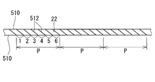
- FIG. 6 is an explanatory view for explaining a method of measuring the thickness of an oxide film in Test Example 1; It is explanatory drawing explaining the measuring method of a twisted wire pitch about the twisted wire which comprises the conductor with which a coated electric wire is equipped.
- Test Example 1 sample nos. It is a microscope picture which expands and shows a part of conductor in the cross section of the conductor of 1-1.
- the contact resistance is small when the terminal portion is crimped and fixed to a stranded wire conductor having a cross-sectional area of 0.22 mm 2 or 0.13 mm 2 , and the crimp height is 0.76.
- the degree of compression is increased, it is easy to break the twisted state of the stranded wire and secure a large contact area between each strand and the terminal portion, and it is easy to lower the contact resistance. Conceivable.
- the larger the degree of compression the smaller the remaining area ratio (described in detail later) of the compressed portion of the terminal portion in the conductor. Therefore, for example, in the compressed portion of the terminal portion of the conductor and in the vicinity thereof, the force (N) which can withstand without impact when impacted is small compared to the non-compressed portion where the terminal portion in the conductor is not attached , Vulnerable to impact resistance. If the degree of compression is reduced, the remaining area ratio of the compressed portion of the terminal portion in the conductor and its vicinity can be largely secured, and excellent characteristics of the non-compressed portion, for example, impact resistance can be maintained, and the terminal is excellent in impact resistance. It can be a wire.
- the ratio of the remaining area of the compression point of the terminal portion in the conductor is particularly 0. Even in the case of more than 76, a coated wire with low contact resistance is desired.
- a coated wire according to an aspect of the present disclosure is: A coated wire comprising a conductor and an insulating covering layer covering an outer periphery of the conductor,
- the conductor is a stranded wire in which a plurality of strands of copper alloy are concentrically twisted,
- the copper alloy contains 0.01% by mass or more in total of one or more elements selected from Fe, Ti, Mg, Sn, Ag, Ni, In, Zn, Cr, Al, and P; Containing up to 5% by mass, the balance being composed of Cu and unavoidable impurities,
- the amount of oil adhesion on the surface of the central strand disposed in the center of the twisted wire is 10 ⁇ g / g or less with respect to the mass of the central strand.
- the above-mentioned oil is typically a mineral oil, a synthetic oil, etc., and is derived from a lubricant used in the production process (which may also have a function other than a lubricating function such as a discoloration prevention function). .
- the above-mentioned oil typically includes a lubricant used in plastic working such as wire drawing.
- the above-mentioned concentric twist means that at least one strand is a central strand, and a plurality of outer strands are concentrically twisted so as to cover the outer circumference of the central strand.
- the above-mentioned stranded wire includes a plurality of strands (here, copper alloy wires) as twisted and includes not only non-compressed non-compressed twisted wire but also compressed twisted wire which is compression-molded after twisting. .
- the above-mentioned coated electric wire makes a conductor a twisted strand concentrically twisted, it is hard to buckle for the following reasons.
- the amount of oil attached to the surface of the central strand constituting the stranded wire is small.
- the oil adhesion amount on the surface of the central strand is small, the oil adhesion amount on the surface of each outer peripheral strand is also small, and consequently the oil adhesion amount on the surface of all strands constituting the twisted wire is It can be said that there are few.
- the oil present between the strands and the oil present between the outer sheath forming the outermost part of the conductor and the insulation coating layer are small, and the friction between the strands and the friction between the outer sheath and the insulation sheath are It is easy to grow. It can be said that the above-mentioned coated electric wire which uses such a stranded wire as a conductor is excellent in rigidity since the strands, the conductor and the insulation coating layer do not slip easily, and they are easily moved together.
- the friction between the strands or the friction between the conductor and the insulation coating layer is as described above. Because it is large, it is excellent in rigidity.
- the above-mentioned coated wire is difficult to be buckled by being excellent in rigidity as a whole of the coated wire as described above.
- the above-mentioned coated electric wire is used for an electric wire with a terminal, when the terminal portion is inserted into the terminal storage portion of the housing or the like, the vicinity of the terminal portion is unlikely to be buckled, and the insertion workability is excellent.
- the above-described coated electric wire has low contact resistance with the terminal when the terminal is attached to the end.
- the oil adhering to the surface of each strand constituting the above-mentioned conductor is generally an electrical insulating material, but in the above-mentioned coated electric wire, the oil is small as described above, so the amount of oil interposed between the conductor and the terminal is small It is from.
- the above-mentioned oil adhesion amount is large to a certain extent, if the terminal portion is attached with a large degree of compression, rubbing of the strands locally occurs at the compression location of the terminal portion in the conductor to remove oil. It is considered that the contact resistance can be easily lowered.
- the coated electric wire described above can reduce the contact resistance even if the degree of compression is reduced because the amount of oil attached is small. If the degree of compression is small, the ratio of the remaining area of the compressed portion of the terminal portion in the conductor can be increased, and excellent characteristics of the non-compressed portion in the conductor can be maintained. For example, if the conductor is excellent in impact resistance, the terminal is excellent in impact resistance even when the cross-sectional area is small, particularly 0.22 mm 2 or less, further 0.2 mm 2 or less, and 0.15 mm 2 or less. You can build a wire. Such a coated electric wire has low contact resistance and impact resistance even when the cross section of the conductor is small as described above, and further when the degree of compression is smaller, when it is used for a terminal-attached electric wire. It is also excellent in
- the above-mentioned coated electric wire is excellent in welding strength when a branch wire etc. are welded to the conductor which consists of a concentric twisted wire.
- a branch wire etc. are welded to the conductor which consists of a concentric twisted wire.
- the said form has a film which consists of copper oxides containing an electrical insulation material, this film is thin enough. Therefore, the said form tends to reduce the contact resistance with a terminal part more. Moreover, the said form reduces the fall of the welding strength by presence of a copper oxide, and is more excellent by welding strength.
- the above-mentioned form is more difficult to buckle because of high tensile strength. Moreover, the said form is excellent by welding strength. Furthermore, the above-mentioned form is excellent also in impact resistance since both tensile strength and breaking elongation are high.
- the cross-sectional area of the conductor is 0.22 mm 2 or less
- the cross-sectional area of the conductor is small, the twist pitch of the stranded wire is long, so the strength is excellent and buckling is more difficult.
- the minimum distance from the crown portion excluding the twist groove to the outer peripheral surface of the insulating covering layer is the thickness of the insulating covering layer;
- the ratio of the minimum value of the thickness to the maximum value of is 80% or more.
- the said form is provided with the insulation coating layer with uniform thickness with respect to the conductor, the rigidity by integration of a conductor and an insulation coating layer is heightened more, and it is more difficult to buckle.
- the terminal-equipped wire according to an aspect of the present disclosure is: The coated electric wire according to any one of the above (1) to (5), And a terminal portion attached to an end of the coated wire.
- the above-mentioned terminal-equipped electric wire is provided with the above-mentioned coated electric wire which uses the above-mentioned stranded wire with a small amount of oil adhesion as a conductor, it is difficult to buckle as described above, the contact resistance between the conductor and the terminal portion is low, It produces an effect of being excellent.
- the ratio of the cross-sectional area of the compression portion to which the terminal portion is attached to the cross-sectional area of the uncompressed portion to which the terminal portion is not attached in the conductor is the remaining area ratio, and the residual area ratio is more than 0.76 Can be mentioned.
- the conductor remaining area at the compressed portion of the terminal portion in the conductor is large, the amount of oil adhesion is small as described above, so the contact resistance is low. Moreover, since the said conductor residual area is large, the said form can maintain the characteristic of the non-compression location in a conductor, for example, impact resistance etc., and is excellent also in impact resistance etc.
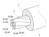
- the covered electric wire 1 of embodiment is provided with the conductor 2 and the insulation coating layer 3 which covers the outer periphery of the conductor 2 as shown in FIG.
- the conductor 2 is a stranded wire in which a plurality of strands 20 composed of a copper alloy are concentrically twisted.
- the copper alloy contains 0.01% or more in total of one or more elements selected from Fe, Ti, Mg, Sn, Ag, Ni, In, Zn, Cr, Al, and P. % Or less, and the balance consists of Cu and unavoidable impurities.
- the stranded wire is formed by concentrically twisting a plurality of outer peripheral strands 22 around the outer periphery of one or more central strands 21.
- the coated electric wire 1 of the embodiment is characterized in that, of the strands 20 constituting the conductor 2, the amount of oil attached to the surface of the central strand 21 disposed at the central portion of the stranded wire is small. Quantitatively, the amount of oil attached to the surface of the central strand 21 is 10 ⁇ g / g or less with respect to the mass (g) of the central strand 21.
- the conductor 2 and the insulating covering layer 3 will be described in order.
- Each strand 20 which comprises the conductor 2 is a wire comprised from the copper alloy which contains an additional element and the remainder contains Cu and an unavoidable impurity.
- the additive element includes one or more elements selected from Fe, Ti, Mg, Sn, Ag, Ni, In, Zn, Cr, Al, and P.
- the total content of additive elements is 0.01% or more and 5.5% or less. Although depending on the type of the additive element, the tensile strength tends to be high as the total content of the additive element is high, the strength and the rigidity are excellent, and the conductivity tends to be high as the content is small. The following may be mentioned as specific compositions (the balance is Cu and unavoidable impurities).
- Composition (3 solid solution type alloy) Sn is contained at 0.15% or more and 0.7% or less.
- Composition (4 solid solution type alloy) Mg is contained at 0.01% or more and 1.0% or less.
- the content of Fe is 0.4% or more and 2.0% or less, and further 0.5% or more and 1.5% or less
- the content of Ti is 0.1% to 0.7%, further 0.1% to 0.5%
- the content of Mg is 0.01% or more and 0.5% or less, and further 0.01% or more and 0.2% or less
- the content of Sn is 0.01% or more and 0.7% or less, and further 0.01% or more and 0.3% or less
- the content of Ag is 0.01% or more and 1.0% or less, and further 0.01% or more and 0.2% or less
- the total content of Ni, In, Zn, Cr, Al and P can be 0.01% or more and 0.3% or less, and further 0.01% or more and 0.2% or less.
- the content of Fe is 0.2% or more and 1.5% or less, and further 0.3% or more and 1.2% or less
- the content of P is 0.1% or more and 0.6% or less, and further 0.11% or more and 0.5% or less
- the content of Mg is 0.01% or more and 0.5% or less, and further 0.02% or more and 0.4% or less
- the content of Sn can be 0.05% or more and 0.6% or less, and further 0.1% or more and 0.5% or less.
- the content of Sn can be 0.15% or more and 0.5% or less, and further 0.15% or more and 0.4% or less.
- the content of Mg can be 0.02% or more and 0.5% or less, and further 0.03% or more and 0.4% or less.
- one or more elements selected from C, Si, and Mn can be contained in total of 10 ppm or more and 500 ppm or less. These elements can function as antioxidants for the above-described elements such as Fe and Sn.
- the copper alloy constituting each wire 20 is a precipitation type copper alloy (for example, the above-mentioned compositions (1), (2), etc.) that forms precipitates when subjected to an aging treatment, the aging treatment is applied.
- the aging treatment is applied.
- it typically has a texture containing precipitates.
- the precipitates have a uniformly dispersed structure, it is possible to expect high strength by precipitation strengthening, high conductivity by reduction of the amount of solid solution of additive elements, and the like.
- the said copper alloy has a structure
- the knowledge that welding strength is easy to be acquired was acquired.
- the vertical cross section of the conductor 2 is microscopically observed, and in this observation image, the number of precipitates having a particle diameter of 1 ⁇ m or more is less than 20,000 per 1 mm 2 (20,000 / Mm 2 ) is preferable. If there are many coarse precipitates in the conductor 2 before welding, it becomes difficult to melt the conductor 2 and welding can not be properly performed, or these coarse grains remain in the welded portion, and these coarse grains become the origin of cracking. It is because it becomes easy to bring about the fall of welding strength by the reason of becoming.
- the amount of the coarse precipitates be as small as possible, 19,000 pieces / mm 2 or less, and further 15,000 pieces / mm 2 or less, 10,000 pieces / mm 2 or less, It is preferable that the number is 000 / mm 2 or less.
- the size and the number of precipitates can be controlled by adjusting the conditions of the aging treatment according to, for example, the composition of the copper alloy. The detail of the measuring method of a precipitate and the conditions of an aging treatment are mentioned later.
- the longitudinal cross section of the conductor 2 refers to a cross section cut by a plane parallel to the longitudinal direction of the conductor 2.
- the coated electric wire 1 of embodiment has few oil adhesion amounts of the surface of the strand 20. As shown in FIG. Quantitatively, the mass of oil adhering to the surface of the central strand 21 is 10 ⁇ g or less with respect to 1 g of the mass of the central strand 21. When the central strand 21 and the outer circumferential strand 22 are made of copper alloys having the same composition, it is considered that the strands 21 and 22 are manufactured under the same manufacturing conditions. In this case, the oil adhesion amount at the central strand 21 and the oil adhesion amount at the outer circumferential strand 22 are considered to be substantially equal.
- the oil adhesion amount on the surface of the central strand 21 is small, the oil adhesion amount on the surface of the outer peripheral strand 22 is also small, and it can be said that the oil content on the surface of all the strands 20 is small.
- the friction between the adjacent strands of wire 20 and the friction between the conductor 2 and the insulating covering layer 3 tend to be large, and the entire component of the covered electric wire 1 is easily moved as one unit and is not easily buckled.
- the small amount of oil adhesion when the terminal portion is attached to the end of the coated wire 1, the oil content between the conductor 2 and the terminal portion tends to be small, and the contact resistance between the conductor 2 and the terminal portion can be reduced.
- the oil adhesion amount is preferably 9.5 ⁇ g / g or less, more preferably 9 ⁇ g / g or less, and 8.8 ⁇ g / g or less.
- the oil adhesion amount is considered to be preferably 0.5 ⁇ g / g or more, and more preferably 1 ⁇ g / g or more. The measuring method of oil adhesion amount is mentioned later.
- the above-described oil adhering to the surface of the wire 20 is typically derived from a lubricant (such as a lubricant for wire drawing) used in the manufacturing process. Therefore, as a method of reducing the oil adhesion amount, for example, reducing the application amount of the lubricant at the time of wire drawing and the like can be mentioned.
- a heat treatment such as aging treatment or softening treatment
- adjustment of heat treatment conditions to actively reduce and remove oil components may be mentioned.
- a heat treatment may be separately provided to reduce and remove oil. Even when the coating amount of the lubricant is increased at the time of wire drawing, if the heat treatment is performed in the subsequent step, the oil adhesion amount can be reliably reduced and removed.
- the heat treatment conditions will be described later.
- the length of the central strand 21 to be measured is set to 20 m or more when measuring the oil adhesion amount, a large amount of oil to be measured can be secured, and the measurement accuracy can be enhanced.
- the coated wire is in a state of being wound up on a reel, it is rewound to cut out a wire sample piece having a length of 20 m or more, take out the conductor from the wire sample piece, and deposit oil on the central strand It is good to measure
- the length of each coated wire provided in a wire harness for automobile use or robot use may be less than 20 m.
- a plurality of coated wires less than 20 m in length are collected so that the total length of the central wires is 20 m or more, and the conductor is taken out from each of the coated wires. It is good to measure the total amount.
- At least the specifications of the conductors (composition of the strands, the number of strands of the strands, the average cross-sectional area of the strands, the outer diameter of the conductor, etc.) of the coated wires to be collected are considered to be substantially the same.
- each strand 20 When the amount of copper oxide containing an electrical insulating material such as CuO on the surface of each strand 20 is small, the contact resistance between the conductor 2 and the terminal can be reduced when the terminal is crimped to the conductor 2 or the like. Quantitatively, it is preferable to have a film made of copper oxide on the surface of the wire 20 and have a thickness of 10 nm or less.
- a film made of copper oxide may be formed on the surface.
- the thickness of the film is preferably 9.5 nm or less, more preferably 8 nm or less, and 5 nm or less. It is desirable that the film does not exist (the thickness is 0 nm), but the thickness of the film is set to 0.05 nm or more, preferably 0.08 nm or more, in consideration of practical workability in heat treatment and the like. be able to. The measuring method of the thickness of the said film is mentioned later.
- the central strand 21 and the outer circumferential strand 22 consist of copper alloys of the same composition, it is considered that they were manufactured under the same manufacturing conditions. In this case, it is considered that the thickness of the copper oxide coating on the central strand 21 and the thickness of the copper oxide coating on the peripheral strands 22 are substantially equal. However, in the measurement of the thickness of the film, for example, it is considered that the surface of the outer peripheral wire 22 is damaged when removing the insulation coating layer 3 from the coated electric wire 1, and the thickness of the copper oxide film can not be measured properly. Be Therefore, it is considered preferable to perform the thickness measurement on the central strand 21 not in contact with the insulating covering layer 3.
- the contact resistance can be lowered even if the degree of compression at the time of crimping and fixing the terminal portion to the end of the coated wire 1 is reduced.
- the covered electric wire 1 can make it easy to maintain the outstanding characteristic of the non-compression location in the conductor 2 by ensuring largely the remaining area ratio of the compression location of the terminal part in the conductor 2 by being able to make the said compression degree small.
- Such a covered electric wire 1 contributes to the construction of the terminal-equipped electric wire 10 (FIG. 3) which is excellent in characteristics such as impact resistance.
- each strand 20 is smooth, it is easy to bring the two into contact before welding when welding branch wires to the conductor 2, and as a result of which welding can be performed precisely, welding strength can be enhanced.
- both the surface roughness Ra of the central strand 21 and the surface roughness Ra of the outer circumferential strand 22 be 0.05 ⁇ m or less.
- the difference between the surface roughness Ra of the central strand 21 and the surface roughness Ra of the outer circumferential strand 22 be small, specifically, 0.005 ⁇ m or less, further 0.004 ⁇ m or less.
- the surface roughness Ra of the outer peripheral wire 22 may be smaller than that of the central wire 21 by plastic deformation of the outer peripheral wire 22 by compression molding ( See the test examples below).
- the surface roughness Ra As a method of reducing the surface roughness Ra, it is possible to use one having a small surface roughness Ra of the inner peripheral surface of a wire drawing die used in wire drawing or the like, for example, one having a diameter of 0.05 ⁇ m or less.
- the surface roughness of the wire drawing die is easy to measure, for example, using the surface roughness of the wire drawing material as a substitute value.
- the cross-sectional area of the conductor 2 (the total cross-sectional area of the strands 20 constituting the stranded wire) can be appropriately selected according to the application of the coated wire 1.
- a lightweight coated electric wire 1 can be obtained.
- Such a covered electric wire 1 can be suitably used for applications where weight reduction is desired, for example, a wire harness for automobiles.
- the cross-sectional area can be 0.2 mm 2 or less, and further 0.15 mm 2 or less, 0.13 mm 2 or less.
- each strand 20 before twisting may be selected so that the cross-sectional area of the conductor 2 has a predetermined size.
- the strands 20 before twisting may include strands 20 having different cross-sectional areas and shapes, but if the cross-sections and shapes of the strands 20 are the same, it is easy to adjust the twisting conditions.
- the number of strands of the stranded wire constituting the conductor 2 can be appropriately selected, and in addition to seven, nineteen, thirty-seven, etc., the central strand 21 may be two or more wires. it can.
- one outer circumferential layer composed of six outer circumferential strands 22 is provided on the outer circumference of one central strand 21.
- the 19-twist has two outer layers, and the 37-twist has three outer layers.
- the twisted wire which comprises the conductor 2 is the non-compressed twisted wire (refer FIG. 1) with the strand 20 twisted together, a compression molding process can be made unnecessary.
- a compressed stranded wire (see FIG. 2) formed by compression molding after twisting the twisted wires constituting the conductor 2, the following effects can be obtained.
- the outer diameter of the stranded wire can be made smaller than that of the non-compressed twisted wire, and the coated wire 1 with a small diameter can be obtained.
- the cross-sectional shape can be made into a desired shape such as a circular shape, Easy to form the insulating covering layer 3 The improvement of the strength by work hardening at the time of compression processing can be expected.
- the cross section of the conductor 2 means the cross section cut
- the ratio of the cross-sectional area reduced by compression molding to the total cross-sectional area of the strands 20 before twisting (for example, the total area of seven strands 20 in the case of seven strands), ie ⁇ (twisting Assuming that the total cross-sectional area of the previous strand-cross-sectional area of the compressed stranded wire) / total cross-sectional area of the strands before twisting ⁇ ⁇ 100 is the compression ratio (%) of the compressed stranded wire, the larger this compression ratio, the stronger the strength It is easy to improve.
- the compression ratio may also affect the surface roughness of the wire (see the test example described later). For example, if it is too large, the surface roughness of the wire disposed on the outer peripheral side becomes very small. The difference between the surface roughness Ra of the strands disposed inside and the surface roughness Ra of the strands disposed on the outer peripheral side tends to be large. The relatively large surface roughness of the inner strands can lead to a decrease in weld strength.
- the compression ratio of the compressed stranded wire is preferably 10% to 30%, and more preferably 12% to 25%, 12% to 20%, in consideration of improvement of strength, securing of toughness and impact resistance, improvement of welding strength, etc.
- the compression ratio can be set in advance in the manufacturing process, and can be in the above-mentioned range by compression molding based on the set value.
- the minimum enveloping circle that includes the central strand 21 among the strands 20 forming the conductor 2 is taken, and the cross-sectional area of this enveloping circle ⁇ the number of strands is the total of the strands before twisting. In some cases, it may be possible to simply measure the compression ratio of the above-mentioned compressed stranded wire assuming a cross-sectional area.
- twist pitch of the outer peripheral strand 22 of the stranded wire which comprises the conductor 2 can be suitably selected according to the cross-sectional area of the conductor 2, etc.
- the cross-sectional area of the conductor 2 is small, in particular when it is 0.22 mm 2 or less, when the twist pitch of the stranded wire is long to a certain extent, particularly when it is 12 mm or more, further 14 mm or more, the covered electric wire 1 is excellent in strength and difficult to buckle can do.
- the longer the twist pitch the easier it is to increase the strength, and it can be made 14.5 mm or more, and further 15 mm or more, 15.5 mm or more.
- the twisting pitch when the cross-sectional area of the conductor 2 is 0.22 mm 2 or less is preferably 20 mm or less, and more preferably 16 mm or less.
- the above-mentioned twist pitch can be previously set in the manufacturing process, and can be made into the above-mentioned range by twisting a plurality of strands 20 based on setting values.
- it carries out as follows, for example.
- a coated electric wire 1 of a predetermined length (for example, 100 mm or more) is prepared, and in a state where both ends of the coated electric wire 1 are fixed, the insulating coating layer 3 is removed by a suitable cutting tool such as feather to expose the conductor 2 .
- a thin sheet of paper such as Japanese paper or tracing paper is placed on the exposed portion of the conductor 2, and a pencil or the like traces the twist groove and the outer peripheral edge of the conductor in the axial direction.
- the two outer peripheral edges 510 and 510 are disposed in parallel as shown in FIG. It is represented by an oblique line (typically, a deeply traced line) intersecting the peripheral edge 510.
- One outer peripheral wire 22 is between adjacent twist grooves 512, 512.
- the length P along the outer peripheral edge 510 is measured with a ruler or the like for every six outer peripheral strands 22 (for every seven twist grooves 512).
- the outer shape of the conductor 2 has a shape corresponding to the twisted state (see FIGS. 1 and 2).
- the compression stranded wire typically has a cross-sectional shape or an end surface shape close to a circle (see FIG. 2).
- the cross-sectional shape can also be made into a polygonal shape such as an elliptical shape or a hexagonal shape.
- the conductor 2 has a tensile strength of 450 MPa or more, a breaking elongation of 5% or more of the conductor 2 and a conductivity of 55% of IACS or more. It can be If the tensile strength is 450 MPa or more, the strength is high and buckling is difficult. Moreover, it is excellent in welding strength. If the breaking elongation is 5% or more, it is easy to bend. If the conductivity is 55% IACS or more, the conductivity is excellent, and the cross-sectional area of the conductor 2 can be easily reduced.
- the tensile strength is 450 MPa or more and the breaking elongation is 5% or more, it is excellent in both the strength and the toughness and is more excellent in impact resistance and preferable. It is more preferable to satisfy all the three matters listed.
- the tensile strength can be set to 460 MPa or more, further 465 MPa or more, 470 MPa or more, and further 500 MPa or more.
- the breaking elongation can be 6% or more, further 7% or more, 8% or more, or 10% or more.
- the conductivity can be 60% IACS or more, further 65% IACS or more, 70% IACS or more.
- the tensile strength, the elongation at break, and the conductivity can typically be set to predetermined values by adjusting the composition and manufacturing conditions of the copper alloy. For example, if the number of added elements is increased or the degree of wire drawing is increased to use a thin wire 20, the tensile strength tends to be high and the conductivity to be low. For example, when heat treatment temperature is increased when heat treatment is performed, breaking elongation tends to be high and tensile strength tends to be low. In the precipitation type copper alloy, when the aging treatment is performed, the conductivity tends to be high.
- the insulating material which comprises the insulation coating layer 3 includes, for example, polyvinyl chloride (PVC), halogen-free resin (for example, polypropylene (PP), etc.), a material having excellent flame retardancy, and the like.
- PVC polyvinyl chloride
- halogen-free resin for example, polypropylene (PP), etc.
- PP polypropylene
- a well-known insulating material can be utilized for the said insulating material.
- the thickness of the insulation coating layer 3 can be suitably selected in the range which has predetermined
- the average thickness of the insulating covering layer 3 is preferably 0.21 mm or more, and more preferably 0.22 mm or more and 0.23 mm or more. It is because the rigidity improvement of the covered electric wire 1 by thickening of the insulation coating layer 3 can be anticipated, and it can be hard to be buckled. With the average thickness, as shown in FIG.
- the average thickness corresponds to the average distance from the smallest envelope circle 200 containing the conductor 2 to the outer peripheral surface of the insulating covering layer 3.
- the insulating covering layer 3 is preferably formed to a uniform thickness with respect to the conductor 2. This is because the integration of the conductor 2 and the insulating covering layer 3 can easily increase the rigidity and make it difficult to buckle.
- the ratio of the minimum value of the thickness t n to the maximum value of the thickness t n (hereinafter referred to as the thickness uniformity ratio) is 80% or more.
- the greater the uniformity of the thickness the more the thickness of the insulating covering layer 3 can be said to be uniform, and the more difficult the buckling is, the more preferred is 80.5% or more, further 82% or more. It is most preferable that all the thicknesses t n be equal, that is, the uniformity of the thickness be 100%.
- the uniformity of the thickness is large, it can be said that the axis of the conductor 2 and the axis of the insulating covering layer 3 are close to coaxial, and the degree of eccentricity of the insulating covering layer 3 with respect to the conductor 2 is small.
- the thickness of the portion filling the twist groove 25 is thicker than the thickness of the portion covering the crown portion 220.
- the thickness of the portion covering the twist groove 25 has the maximum thickness t max
- the thickness of the portion covering the crown portion 220 has the minimum thickness t min .
- t 1 is illustrated as the minimum thickness t min .
- the thickness ratio is preferably 0.6 or more and 0.9 or less, and more preferably 0.61 or more and 0.88 or less, and can be 0.62 or more and less than 0.85 from the viewpoint of making the buckling difficult.
- the covered electric wire 1 of embodiment can be utilized for various wiring.
- it is suitable for the use etc. which are used in the state to which the terminal part was attached to the edge part of the coated wire 1.
- the coated electric wire 1 can be used for wiring of various electric devices such as devices such as automobiles and airplanes and control devices such as industrial robots, for example, wiring of various wire harnesses such as wire harnesses for automobiles.
- the terminal-attached electric wire 10 of the embodiment includes the coated electric wire 1 of the embodiment as shown in FIG. 3 and the terminal portion 4 attached to the end of the coated electric wire 1.
- the female or male fitting portion 42 is provided at one end, and the other end is provided with an insulation barrel portion 44 for gripping the insulating covering layer 3 and the conductor 2 is gripped at the intermediate portion.
- the crimp terminal provided with the wire barrel part 40 is illustrated. The crimp terminal is crimped to the end of the conductor 2 exposed by removing the insulating covering layer 3 at the end of the coated wire 1 and electrically and mechanically connected to the conductor 2.
- melt and connect the conductor 2 is mentioned.
- the terminal-equipped electric wire 10 may have a mode in which one terminal portion 4 is provided for a plurality of coated electric wires 1, in addition to a mode (FIG. 3) in which one terminal portion 4 is attached to each coated electric wire 1.
- a mode FOG. 3
- the terminal-equipped wire 10 can be handled easily.
- the ratio of the cross-sectional area of the compression portion to which the terminal portion 4 is attached to the cross-sectional area of the non-compression portion to which the terminal portion 4 is not attached When the remaining area ratio is large, it is preferable because the characteristics such as impact resistance are excellent even if the cross-sectional area of the conductor 2 is small as described above. Quantitatively, it is mentioned that the residual area ratio is more than 0.76. As the remaining area ratio is larger, the compressed portion of the terminal portion 4 in the conductor 2 can easily maintain the excellent characteristics of the non-compressed portion in the conductor 2, and the entire terminal-equipped wire 10 is excellent in impact resistance and the like. In consideration of the improvement of impact resistance etc., the above-mentioned ratio of the remaining area can be made 0.77 or more, further 0.78 or more, 0.79 or more, 0.80 or more.
- the residual area ratio adjusts the degree of compression at the time of attaching the terminal portion 4, and in particular, reduces the crimp height (C / H, the height of the wire barrel portion 40 in the terminal-attached electric wire 10)
- the adjustment can satisfy the above-mentioned range. Since the electric wire 10 with a terminal according to the embodiment has the covered electric wire 1 whose conductor 2 is a stranded wire with a small amount of oil adhesion as described above, the conductor 2 and the terminals can be used even if the degree of compression is small as described above. The contact resistance between the parts 4 can be reduced (see the test example described later).
- the non-compression portion of the conductor 2 in the terminal-attached electric wire 10 of the embodiment maintains the specifications (composition, structure, surface texture, twisting state, shape, characteristics, etc.) of the conductor 2 provided in the coated electric wire 1 of the embodiment described above. Or have similar characteristics and the like. The details of each item are as described above.
- the terminal-attached electric wire 10 of the embodiment can be used for wiring of various electric devices such as the above-described automobile, airplane, control device, etc., particularly for wiring of various wire harnesses such as automobile wire harness.
- branching can be performed by welding a branch wire or the like to a part of the conductor 2.
- the conductor 2 is unlikely to interpose a modified substance or the like due to the oil component at the welding portion, and the welding strength is excellent.
- a branch line can be made into the thing of the same composition as the covered electric wire 1 of an embodiment, and the electric wire 10 with a terminal of an embodiment.
- a coated electric wire provided with a copper conductor composed of pure copper can be mentioned.
- the coated electric wire 1 of the embodiment or the terminal-equipped electric wire 10 of the embodiment the branch covered electric wire including the copper conductor composed of pure copper, the exposed portion exposed from the insulating coating layer 3 in the conductor 2 and the copper conductor
- the copper conductor composed of pure copper
- the exposed portion exposed from the insulating coating layer 3 in the conductor 2 and the copper conductor It is possible to construct a welded structure of the electric wire comprising a welding part welded with a part. Pure copper is generally less strong than copper alloys. Therefore, in the welded structure of the electric wire, if the cross-sectional area of the copper conductor is made larger than that of the conductor 2 made of copper alloy, it is easy to increase the strength of the welded portion.
- the copper alloy constituting the conductor 2 contains the above-mentioned precipitates, if it is a structure with few coarse precipitates as described above, it becomes close to the structure of pure copper substantially free of precipitates, It is easy to perform welding, and it is easy to increase the bonding strength.
- the conductor 2 is a twisted strand of concentric twist, and the oil adhesion amount of the surface of the strand 20 is a specific range, so that the conductor 2 is difficult to buckle
- a special effect is achieved such as low contact resistance between the terminal portion 4 and the terminal portion 4 and excellent welding strength when a branch wire or the like is welded.
- the coated electric wire 1 of the embodiment can be manufactured typically by the manufacturing method including the steps of preparing the conductor 2 made of a copper alloy and forming the insulating covering layer 3 on the outer periphery of the conductor 2.
- the conductor 2 is a stranded wire in which a plurality of strands 20 made of copper alloy are concentrically twisted.
- each strand 20 is manufactured including a step of casting a copper alloy, a step of subjecting the cast material to plastic working such as rolling or conform extrusion, and a step of subjecting the plastic worked member to wire drawing. It can be manufactured by the method.
- Various types of continuous casting can be used for casting.
- As a raw material to be subjected to wire drawing it can be used as a continuously cast and rolled material which is rolled subsequently to continuous casting.
- Heat treatment can be appropriately performed during wire drawing or after wire drawing.
- the basic manufacturing conditions can be referred to the known copper alloy wire manufacturing method.
- the above-mentioned oil adhesion amount can satisfy the above-mentioned specific range.
- the oil content can be positively reduced and removed by heat treatment regardless of the adjustment of the application amount.
- the surface roughness Ra of the inner circumferential surface of the wire drawing die is small (the details are described above), the surface roughness Ra of the wire 20 can be set to the above-described specific range.
- the wire drawability can be enhanced or it becomes easy to twist, and the productivity of the wire drawing material (wire 20) and the twisted wire (conductor 2) can be improved. .
- twist pitch is made longer to some extent as described above, the strength of the stranded wire can be easily increased even when the cross-sectional area of the conductor 2 is small, and the coated electric wire 1 that is hard to buckle can be easily manufactured. After twisting, it can be compression molded at a predetermined compression ratio (details described above) to form a compressed stranded wire of a predetermined shape.
- the compression ratio may be adjusted in a range in which the cross-sectional area of the conductor 2 satisfies a predetermined size (details described above).
- a predetermined size e.g., a predetermined size
- an improvement in strength can be expected while suppressing a decrease in toughness and a decrease in impact resistance.
- the strands 20 before twisting or the as-twisted strands or compression strands may be subjected to heat treatment such as aging treatment or softening treatment to strengthen the precipitates. Improvement of strength (precipitation type alloy) or conductivity improvement by reduction of solid solution elements (precipitation type alloy, solid solution type alloy), improvement of elongation by softening, improvement of impact resistance (precipitation type alloy, solid solution type alloy) Can be expected.
- heat treatment for the purpose of aging treatment and softening treatment, the oil content may be reduced, and it may be easy to manufacture the coated electric wire 1 in which the above-mentioned oil adhesion amount satisfies 10 ⁇ g / g or less.
- the coated electric wire 1 in which the above-mentioned oil adhesion amount satisfies 10 ⁇ g / g or less is easily manufactured.
- composition (1) Heat treatment temperature: 400 ° C. to 650 ° C., and further 450 ° C. to 600 ° C. Holding time: 1 hour to 40 hours, further 4 hours to 20 hours
- Composition (2) Heat treatment temperature: 350 ° C. to 550 ° C.
- degreasing may be performed on the stranded wire or the compressed stranded wire.
- the degreasing solution is preferably a solution containing an alcohol system.
- an atmosphere having an oxygen content of 0.1% by volume or less is mentioned.
- a low oxygen atmosphere for example, a reducing atmosphere, an inert atmosphere, a reduced pressure atmosphere and the like can be mentioned.
- the reducing atmosphere may be an atmosphere substantially consisting only of a reducing gas, or an atmosphere substantially consisting of a mixed gas of a reducing gas and an inert gas.
- the reducing gas may, for example, be hydrogen or carbon monoxide.
- the inert gas may, for example, be nitrogen or argon.
- the reduced pressure atmosphere may be, for example, an atmosphere of 10 Pa or less. Depending on the composition, it is preferable to lower the oxygen content, for example, 10 ppm by volume or less.
- An extrusion method etc. can be utilized for formation of the insulation coating layer 3.
- the insulation coating layer 3 when the twisted wire is heated, it is easy to fill the molten resin along the twist groove 25 or adhere the molten resin with a uniform thickness to the outer periphery of the twisted wire. It is easy. As a result, it is easy to manufacture the covered electric wire 1 in which the uniform ratio of the thickness of the insulation coating layer 3 is high as mentioned above, and the covered electric wire 1 whose thickness ratio is a specific range.
- the heating temperature of the stranded wire may be about ⁇ 10 ° C. of the resin in the molten state, preferably about the same as the temperature of the resin in the molten state.
- the above-described reduction in the amount of oil adhesion can be expected also by this heating.
- the above-mentioned copper oxide film does not easily become thick.
- the terminal portion 4 is a crimped terminal
- crimping is performed with a predetermined crimp height (C / H).
- C / H crimp height
- Test Example 1 A stranded wire with concentric twist is prepared using copper alloy wire as a strand, and a coated electric wire using this stranded wire as a conductor is prepared, and a terminal portion is attached to the end to make a buckling state and contact resistance with the terminal portion Examined. In addition, a copper conductor was welded to the above-mentioned coated electric wire to examine the welding strength.
- the copper alloy wire to be used as the wire is prepared by cold-rolling a continuously cast material produced using a molten metal of copper alloy, drawing the obtained rolled material, or using a molten metal of copper alloy
- the continuous casting and rolling material produced is subjected to wire drawing processing. After twisting the obtained copper alloy wire, it compression-molds and produces a compression stranded wire. Heat treatment is applied to the compressed stranded wire as appropriate.
- the copper alloy wire (wire drawing material) is heat-treated and twisted, and then compression molded.
- Table 1 shows the composition (remaining part Cu and unavoidable impurities) of the copper alloy of each sample, and the manufacturing process of each sample.
- the heat treatment temperature (° C.) and the holding time (hour) are also shown in Table 1 for the samples subjected to the heat treatment.
- the heat treatment atmosphere is a reducing atmosphere mainly containing hydrogen (oxygen content: 0.1 volume% or less).
- the surface roughness Ra of the inner circumferential surface of the wire drawing die is 0.05 ⁇ m or less.
- Sample No. 1-101 to No. In 1-105 one having a surface roughness Ra of more than 0.05 ⁇ m on the inner peripheral surface of a wire drawing die is used. Wire drawing is performed using a lubricant for any of the samples.
- the compression ratio (%) is determined by ⁇ (total cross-sectional area of seven strands before twist-cross-section of compressed stranded wire) / total cross-section of seven strands before twist ⁇ ⁇ 100 .
- values shown in Table 2 were obtained. It has confirmed that it is substantially equal.
- an insulation covering layer of the constituent material shown in Table 2 is formed by extrusion so as to have a thickness (mm) shown in Table 2.
- PVC polyvinyl chloride
- HF (PP) halogen-free polypropylene.
- the thickness of the insulating covering layer is the average of the thickness (see t 1 to t 6 in FIG. 2) of the portion covering the above-mentioned crown portion.
- the average thickness of the insulation coating layer of the finally obtained coated electric wire of each sample was measured as described in the section ⁇ Thickness> above, and was substantially equal to the values shown in Table 2. Have confirmed that.
- the insulation coating layer is formed in a state where the conductor is heated to a temperature selected from the temperature ⁇ 10 ° C. of the molten resin.
- Sample No. 1-102, no. 1-104, no. In 1-105, the insulation coating layer is formed with the conductor at normal temperature (about 20 ° C. here).
- the amount of oil adhesion ( ⁇ g / g) on the surface of the central strand of the stranded wire constituting the conductor was measured as follows for the coated wire of each sample prepared. The results are shown in Table 2.
- the coated wire is cut into a predetermined length (here, 20 m), and the insulating coating layer is removed by a suitable cutting tool such as feather to expose the conductor.
- the outer peripheral wire is removed in such a way as to untwist it, and only the central wire is taken out.
- the thickness (nm) of the film made of copper oxide which may be present on the surface of the strands constituting the conductor was measured as follows for the coated wire of each sample prepared. The results are shown in Table 2.
- the coated wire is cut into a predetermined length, and the insulating coating layer on one end side of the coated wire is removed by a suitable cutting tool such as feather to expose the conductor, and further, the outer peripheral element of the stranded wire constituting the conductor
- the wire is removed in an untwisted manner, exposing only the central strand. At this time, the surface of the central strand is not damaged.
- the exposed length of the central strand is about 2 cm (20 mm), and the remaining part has an insulating covering layer.
- the oxide film that may be present on the surface of the exposed central strand is analyzed and quantified by electrochemical measurement.
- a commercially available potentio / galvanostat (Princeton Applied Research, Inc .: VersaSTAT 4-400) was used as a measuring device for the electrochemical measurement.
- As the electrolyte a high concentration alkaline solution (a mixed solution of 6 M KOH and 1 M LiOH, M is a molar concentration) was used. As shown in FIG.
- One end of the counter electrode 502 and one end of the reference electrode 504 are immersed in the electrolyte solution 506, and the other ends thereof are attached to the measuring device 500.
- the immersion depth of the central strand in the electrolyte is about 2 cm.
- the potential is swept from the natural immersion potential to -1.7 V (vs. Ag / AgCl) at a sweep rate of 50 mV / s to measure the position of the reduction peak and the reduced charge.
- the composition of the film and its thickness are determined from the measured position of the reduction peak and the amount of reduction electricity.
- the components of the film mainly include copper oxides such as CuO and Cu 2 O. Here, the thickness of the film made of copper oxide is determined.
- the tensile strength (MPa) of the conductor and the breaking elongation (%) of the conductor were measured as follows for the coated wire of each sample prepared. The results are shown in Table 2.
- the coated wire is cut into a predetermined length, and the insulating coating layer is removed by a suitable cutting tool such as feather to expose the conductor.
- a tensile test was performed using a general-purpose tensile tester with a marking distance GL of 250 mm and a tensile speed of 50 mm / min according to JIS Z 2241 (Metal Material Tensile Test Method, 1998) .
- the tensile strength (MPa) was determined from ⁇ breaking load (N) / cross-sectional area of conductor (mm 2 ) ⁇ .
- the breaking elongation (total elongation,%) was determined from ⁇ breaking displacement (mm) / 250 (mm) ⁇ ⁇ 100.
- the surface roughness Ra ( ⁇ m) of the central strand forming the conductor and the surface roughness Ra ( ⁇ m) of the outer peripheral wire were measured as follows for the coated wires of each sample prepared. The results are shown in Table 2.
- the coated wire is cut into a predetermined length, the insulating coating layer is removed with a suitable cutting tool such as feather to expose the conductor, and the outer peripheral wire of the stranded wires constituting the conductor is untwisted. As a result, the central wire and the outer wire are exposed. At this time, the surface of each wire is not damaged.
- surface roughness Ra was measured using a commercially available non-contact surface profiler (manufactured by zygo: New View 1100).
- the laser microscope provided in the non-contact surface shape measuring machine has a plane equivalent to a circle (a surface along the circumferential direction) for each of the outer peripheral surface of the central strand and the outer peripheral surface of the outer peripheral strand Measure the roughness) and convert the plane.
- Plane conversion can be performed automatically by using the above-mentioned commercially available measuring machine.
- the arithmetic mean deviation from the vertex (center line) in the plane roughness equivalent to a circle is calculated with respect to the plane converted roughness, and this arithmetic mean deviation is taken as the surface roughness Ra.
- the amount of precipitates having a particle diameter of 1 ⁇ m or more present in the strands constituting the conductor was measured as follows for the coated wires of each sample prepared. The results are shown in Table 2. Take a vertical cross section of the coated wire, and observe the strands of the stranded wire with a metallurgical microscope. Here, the magnification is 1,000 times. In the observation image, the precipitates in the copper alloy are respectively extracted to determine the area (see FIG. 6). The diameter of the equivalent area circle of each precipitate is taken as the particle diameter, and the number of precipitates having a particle diameter of 1 ⁇ m or more is counted.
- the total number is divided by the visual field area (100 ⁇ m ⁇ 150 ⁇ m) to determine the number of precipitates of 1 ⁇ m or more per 1 mm 2 of copper alloy (hereinafter referred to as “number ratio”).
- number ratio the number of precipitates of 1 ⁇ m or more per 1 mm 2 of copper alloy
- the annular insulating covering layer is observed with an optical microscope, and a portion in which the twist groove is filled in the inner peripheral edge along the outline of the outer peripheral wire in the insulating covering layer (a part protruding like a mountain toward the center of the insulating covering layer) Except for the above, the minimum distance (see thickness t 1 to t 6 in FIG. 2, here six places) from the crown portion of each outer peripheral wire to the outer peripheral surface of the insulating covering layer is measured. The maximum value and the minimum value are extracted from the determined thicknesses t 1 to t 6 , and (minimum value / maximum value) ⁇ 100 is taken as the thickness uniformity ratio (%).
- the maximum thickness t max and the minimum thickness t min are measured in the insulating covering layer including the portions where the twist grooves are filled, and (t min / t max ) is taken as the thickness ratio.
- the maximum thickness t max is the thickness of the portion filling the twist groove
- the minimum thickness t min is the minimum value among the thicknesses t 1 to t 6 .
- the terminal portion of the terminal-attached electric wire is gripped, and the tip end of the coated electric wire opposite to the terminal portion is pressed against the flat plate.
- the length of the coated electric wire is 10 mm (in the coated electric wire, it protrudes from the grip point of the terminal portion and the length to the tip end), the speed of the gripped electric wire with a terminal is 200 mm / min.
- the load at the time of pressing the tip of the plate against the flat plate is changed to perform the pressing operation. Then, the maximum load when the coated wire is buckled is measured, and this maximum load is taken as a buckling force (N).
- the crimp terminal was attached to the edge part, and the electric wire with a terminal was produced.
- the crimp height was adjusted so that the above-mentioned remaining area ratio would be 0.85 or 0.90.
- the contact resistance (m ⁇ / m) between the conductor and the terminal portion was measured for the prepared terminal-attached wire of each sample based on JASO D 616, automobile part-low voltage wire, item 6.8.
- crimped terminals are attached to each end of the coated wire, and two points 150 mm apart from each crimped terminal are used as measurement points of resistance.
- a power supply is attached to both crimp terminals, the applied voltage is 15 mV, and the conduction current is 15 mA.
- a wire with a terminal provided with crimp terminals at both ends is energized, and the resistance between the above two points is measured. The value obtained by subtracting the resistance of the coated wire from the measured resistance value is taken as the contact resistance (m ⁇ / m). Further, when the contact resistance was 0.4 m ⁇ / m or less, the contact resistance was evaluated as G, and when it was more than 0.4 m ⁇ / m, the contact resistance was evaluated as B. The measurement results and the evaluation results are shown in Table 3.
- the two coated wires including the copper conductor are pulled away from each other.
- the welding portion and the coated electric wire of each sample are arranged in the horizontal direction to fix the coated electric wire, and the two coated electric wires provided with the copper conductor are arranged in the vertical direction Then pull one of them upward and the other downward.
- the tensile test uses a commercially available tensile tester or the like. Measure the maximum load (N) until the welded part breaks, and let this maximum load be the welding strength.
- the copper conductor of pure copper is inferior in strength to the conductor of a copper alloy.
- the total cross-sectional area (mm 2 ) of the two copper conductors of pure copper is more than the cross-sectional area (0.13 mm 2 or 0.08 mm 2 ) of the conductor composed of the copper alloy of each sample. It was enlarged as shown in.
- Adhesion of Insulating Coating Layer The adhesion (N) of the insulating coating layer to the conductor was measured in the following manner based on JASO D 618 for the coated wire of each sample prepared. The results are shown in Table 3. In this test, a 100 mm long coated wire is prepared and the electrical insulation layer is removed at one end to expose the conductor 50 mm long. The exposed conductor is inserted into the through hole of the holding plate. The inner diameter of the through hole is a size (smaller than the outer diameter of the coated wire) which can insert the conductor (slightly larger than the outer diameter of the conductor) but can not insert the insulating coating layer. The holding plate is fixed, and one end of the conductor protruding from the holding plate is pulled. The load at the time of pulling this conductor is changed to perform a pulling operation, the insulation coating layer is peeled from the conductor, and the minimum load when the conductor is pulled out is determined, and this load is taken as the adhesion (N).
- the oil adhesion amount of 1-7 is 10 ⁇ g / g or less, and many samples are 6 ⁇ g / g or less and further 5 ⁇ g / g or less.
- the buckling force of 1-7 is 7N or more.
- sample No. 1 in which the oil adhesion amount is 11 ⁇ g / g or more.
- sample No. 1-105 has a buckling force of 6.5 N or less. 1-1 to No. It can be said that it is easier to buckle than 1-7. From these facts, it can be said that the large amount of oil adhesion on the surface of the above-mentioned strands affects the difficulty in buckling, but it can be made difficult to buckle by reducing the amount of oil adhesion.
- the said contact resistance tends to be generally low, so that there is little oil adhesion amount (for example, comparison comparison of sample No.1-6, No.1-2, No.1-4 same conductor cross-sectional area) .
- sample no. 1-1 to No. In 1-7 the contact resistance is low even when the remaining area of the compressed portion of the terminal portion in the conductor is large, that is, when the remaining area ratio is large (here, the remaining area ratio is 0.90), 0.4 m ⁇ / M or less.
- sample No. 1 in which the oil adhesion amount is 11 ⁇ g / g or more.
- the contact resistance is high compared to 1-7, and most are more than 0.4 m ⁇ / m. In particular, when the ratio of the remaining area is as large as 0.90, sample No. 1 is obtained. 1-101 to No. The contact resistance of 1-105 is as high as 0.45 m ⁇ / m or more. From these facts, it can be understood that the large amount of oil adhesion on the surface of the wire affects the contact resistance between the conductor and the terminal part, and the contact resistance can be reduced by reducing the oil adhesion. .
- 1-101 to No. 1-105 has low welding strength and is 8N or less. From these facts, it can be said that the large amount of oil adhesion on the surface of the above-mentioned wire affects the welding strength when welding the conductor and the branch line etc. By reducing the oil adhesion, the welding strength is enhanced. It can be understood that
- Sample No. 1-1 to No. In 1-7 the film made of copper oxide that can be present on the surface of the strands constituting the stranded wire is thin. Specifically, sample no. 1-1 to No.
- the thickness of the above-mentioned film in 1-7 is 10 nm or less, and in many cases, 5 nm or less and 3 nm or less.
- 1-101 to No. It is 20% or less of the maximum thickness (here, 50 nm) of the above-mentioned coating at 1-105 and is very thin. It is considered that the thinness of the copper oxide film containing the electrical insulating material contributed to the reduction of the contact resistance and the improvement of the welding strength described above. Further, it can be understood from this test that the thickness of the copper oxide film varies depending on the composition of the copper alloy and the heat treatment conditions.
- sample No. 1-1 to No. In 1-7 the tensile strength is large, specifically 450 MPa or more, and there are also samples of 500 MPa or more and 800 MPa or more. It is thought that such high strength contributed to the improvement of the buckling force and the improvement of the welding strength. Also, for sample no. 1-1 to No. Of 1-7, the sample having a breaking elongation of 5% or more is expected to have high strength and high toughness and to be excellent in impact resistance and the like.
- the conductor is made into a compressed stranded wire, and here, the compression ratio is made into the specific range of 10% or more and 30% or less. This can be expected to improve the strength due to work hardening at the time of compression molding, and to contribute to the improvement of the buckling force.
- the surface roughness of each strand is small, and the compression ratio is 10% to 30%, and the difference between the surface roughness Ra of the central strand and the surface roughness Ra of the outer circumferential strand is small. It is thought that it contributed to the improvement of welding strength.
- the compression molding makes the respective strands and the terminal portions be in surface contact with each other, thereby contributing to the reduction in the contact resistance described above.
- the uniformity of the thickness of the insulating covering layer is high, specifically 80% or more, and often 82% or more. This is considered to contribute to the improvement of the buckling force even though the insulating coating layer is uniformly provided to the conductor and as a result, the rigidity of the coated wire as a whole is enhanced.
- the cross-sectional area of the conductor is small as described above, the average thickness of the insulating coating layer is as thick as 0.21 mm or more, and the rigidity is enhanced to contribute to the improvement of the buckling force. Conceivable.
- the thickness ratio of the insulating covering layer is set to a specific range of 0.6 to 0.9, and the resin constituting the insulating covering layer intrudes into the twisted grooves of the stranded wire, and the conductor and the insulating covering layer It is considered that the improvement of the adhesion of the steel also contributed to the improvement of the buckling force. Furthermore, from this test, by forming the insulating covering layer in a heated state of the conductor, even if the insulating covering layer is relatively thick, the constituent resin is suitable for the twist groove with a uniform thickness as described above. It can be seen that it can be filled with
- Sample No. 1-1 to No. In 1-7 the surfaces of the central and outer strands are smooth, and specifically, the surface roughness Ra is 0.05 ⁇ m or less.
- the difference between the surface roughness Ra of the central strand and the surface roughness Ra of the outer circumferential strand is also small, and the difference is 0.005 ⁇ m or less. It is believed that this facilitates the contact between the copper alloy conductor and the pure copper copper conductor during welding, enables accurate welding, and contributes to the improvement of the welding strength.
- Sample No. 1-101, No. 1-102, no. In 1-105 the surface roughness Ra of the outer peripheral wire is larger than the surface roughness Ra of the central wire.
- sample no. 1-101, No. 1-102, no. It is considered that 1-105 is because the above-mentioned compression ratio is too small, the outer peripheral wire hardly undergoes plastic deformation, and the rough surface state before compression is easily maintained.
- No. 1-103, no. In 1-104 the surface roughness Ra of the outer peripheral wire is very small, and the surface roughness Ra of the central wire is very large.
- no. 1-103, no. In 1-104 although the above-mentioned compression ratio is too large, the surface roughness Ra of the outer peripheral wire is greatly plastically deformed to form a smooth portion, but the central wire pushed by the outer peripheral wire has the surface roughness Ra Is considered to have become larger.
- Sample No. 1-1 to No. 1-7 sample No. 1 composed of a precipitation type copper alloy.
- 1-1, no. 1-2, no. 1-4, no. 1-6, no. In 1-7 there are few coarse precipitates of 1 ⁇ m or more, and specifically, 20,000 particles / mm 2 or less.
- FIG. It is a microscope picture of the strand (copper alloy wire) which makes a conductor with which a 1-1 covered wire
- the small amount of coarse precipitates can reduce the difference in structure between the conductor of the copper alloy to be welded and the copper conductor of pure copper. It is believed that this facilitates the contact between the copper alloy conductor and the pure copper copper conductor, enables accurate welding, and contributes to the improvement of the welding strength.
- the present invention is not limited to these exemplifications, but is shown by the claims, and is intended to include all modifications within the scope and meaning equivalent to the claims.
- the composition of the copper alloy of Test Example 1 the cross-sectional area of the copper alloy wire, the number of strands, the heat treatment condition, and the like can be appropriately changed.
Landscapes
- Chemical & Material Sciences (AREA)
- Engineering & Computer Science (AREA)
- Materials Engineering (AREA)
- Mechanical Engineering (AREA)
- Metallurgy (AREA)
- Organic Chemistry (AREA)
- Insulated Conductors (AREA)
- Non-Insulated Conductors (AREA)
- Connections Effected By Soldering, Adhesion, Or Permanent Deformation (AREA)
Abstract
L'invention concerne un fil électrique revêtu qui est équipé d'un conducteur, et d'une couche de revêtement isolant revêtant la périphérie externe dudit conducteur. Ledit conducteur consiste en un fil toronné dans lequel une pluralité de brins configurée par un alliage de cuivre est toronnée de manière concentrique. Ledit alliage de cuivre comprend au total 0,01% en masse ou plus à 5,5% en masse ou moins d'un ou plusieurs éléments choisis parmi Fe, Ti, Mg, Sn, Ag, Ni,In,Zn, Cr, Al et P, le reste étant constitué d'un Cu et des impuretés inévitables. La quantité d'huile en adhésion à la surface d'un brin central disposé dans la partie centrale dudit fil toronné, est inférieure ou égale à 10μg/g par rapport à la masse dudit brin central.
Priority Applications (4)
| Application Number | Priority Date | Filing Date | Title |
|---|---|---|---|
| CN201880046588.0A CN110869525B (zh) | 2017-07-14 | 2018-07-04 | 包覆电线及附带端子的电线 |
| US16/628,458 US11069459B2 (en) | 2017-07-14 | 2018-07-04 | Covered electrical wire and terminal-equipped electrical wire |
| DE112018003618.9T DE112018003618B4 (de) | 2017-07-14 | 2018-07-04 | Ummantelter elektrischer Draht und mit einem Anschluss ausgerüsteter elektrischer Draht |
| JP2019529085A JP6864856B2 (ja) | 2017-07-14 | 2018-07-04 | 被覆電線、及び端子付き電線 |
Applications Claiming Priority (2)
| Application Number | Priority Date | Filing Date | Title |
|---|---|---|---|
| JP2017-138645 | 2017-07-14 | ||
| JP2017138645 | 2017-07-14 |
Publications (1)
| Publication Number | Publication Date |
|---|---|
| WO2019013073A1 true WO2019013073A1 (fr) | 2019-01-17 |
Family
ID=65001978
Family Applications (1)
| Application Number | Title | Priority Date | Filing Date |
|---|---|---|---|
| PCT/JP2018/025419 Ceased WO2019013073A1 (fr) | 2017-07-14 | 2018-07-04 | Fil électrique revêtu, et fil électrique avec borne |
Country Status (5)
| Country | Link |
|---|---|
| US (1) | US11069459B2 (fr) |
| JP (1) | JP6864856B2 (fr) |
| CN (1) | CN110869525B (fr) |
| DE (1) | DE112018003618B4 (fr) |
| WO (1) | WO2019013073A1 (fr) |
Cited By (2)
| Publication number | Priority date | Publication date | Assignee | Title |
|---|---|---|---|---|
| JP2020161263A (ja) * | 2019-03-26 | 2020-10-01 | 古河電気工業株式会社 | ワイヤーハーネス用撚り線 |
| JPWO2023047514A1 (fr) * | 2021-09-24 | 2023-03-30 |
Families Citing this family (7)
| Publication number | Priority date | Publication date | Assignee | Title |
|---|---|---|---|---|
| JPWO2019163541A1 (ja) * | 2018-02-20 | 2021-03-04 | 株式会社潤工社 | 電線、ケーブルハーネス、及び飛翔体 |
| JP6957568B2 (ja) * | 2019-08-09 | 2021-11-02 | 株式会社オートネットワーク技術研究所 | 端子付き電線 |
| JP6936836B2 (ja) | 2019-08-09 | 2021-09-22 | 株式会社オートネットワーク技術研究所 | 端子付き電線 |
| JP2021150230A (ja) * | 2020-03-23 | 2021-09-27 | 株式会社東芝 | 圧着判定方法 |
| CN112298068A (zh) * | 2020-09-25 | 2021-02-02 | 无锡光美新能源科技有限公司 | 一种新型抗氧化高导电的电动车线束及其制备方法 |
| CN114758834A (zh) * | 2022-03-14 | 2022-07-15 | 吉林省中赢高科技有限公司 | 一种电能传输系统及一种汽车 |
| US12549047B2 (en) * | 2023-11-10 | 2026-02-10 | GM Global Technology Operations LLC | Skin effect enhanced high conductive composite stator winding bundles in e-motors |
Citations (3)
| Publication number | Priority date | Publication date | Assignee | Title |
|---|---|---|---|---|
| JP2004107700A (ja) * | 2002-09-13 | 2004-04-08 | Nippon Paint Co Ltd | 電線の塗装方法及び絶縁電線 |
| JP2014032819A (ja) * | 2012-08-02 | 2014-02-20 | Swcc Showa Cable Systems Co Ltd | アルミ電線 |
| JP2015086452A (ja) * | 2013-11-01 | 2015-05-07 | 株式会社オートネットワーク技術研究所 | 銅合金線、銅合金撚線、被覆電線、ワイヤーハーネス及び銅合金線の製造方法 |
Family Cites Families (20)
| Publication number | Priority date | Publication date | Assignee | Title |
|---|---|---|---|---|
| US2842837A (en) * | 1956-04-17 | 1958-07-15 | United States Steel Corp | Method of working wire and a lubricant therefor |
| US3445394A (en) * | 1967-06-27 | 1969-05-20 | Simplex Wire & Cable Co | Voltage stabilized solid polyolefin dielectric |
| JPS6039139A (ja) * | 1983-08-12 | 1985-02-28 | Mitsui Mining & Smelting Co Ltd | 耐軟化高伝導性銅合金 |
| US5149917A (en) * | 1990-05-10 | 1992-09-22 | Sumitomo Electric Industries, Ltd. | Wire conductor for harness |
| US5213644A (en) * | 1991-03-20 | 1993-05-25 | Southwire Company | Method of and apparatus for producing moisture block stranded conductor |
| US6632300B2 (en) * | 2000-06-26 | 2003-10-14 | Olin Corporation | Copper alloy having improved stress relaxation resistance |
| WO2004024964A2 (fr) * | 2002-09-13 | 2004-03-25 | Olin Corporation | Alliage a base de cuivre durcissant par vieillissement et traitement |
| US20040238086A1 (en) * | 2003-05-27 | 2004-12-02 | Joseph Saleh | Processing copper-magnesium alloys and improved copper alloy wire |
| JP2008166141A (ja) * | 2006-12-28 | 2008-07-17 | Auto Network Gijutsu Kenkyusho:Kk | 電線導体および絶縁電線 |
| JP5458707B2 (ja) | 2009-07-08 | 2014-04-02 | 日立金属株式会社 | ケーブル |
| JP6002360B2 (ja) * | 2010-07-21 | 2016-10-05 | 矢崎総業株式会社 | 端子付電線 |
| JP2012146431A (ja) | 2011-01-11 | 2012-08-02 | Auto Network Gijutsu Kenkyusho:Kk | 電線導体及び絶縁電線 |
| JP6134103B2 (ja) * | 2012-06-01 | 2017-05-24 | 矢崎総業株式会社 | 絶縁電線の製造方法 |
| JP5751268B2 (ja) * | 2013-02-14 | 2015-07-22 | 住友電気工業株式会社 | 銅合金線、銅合金撚線、被覆電線、及び端子付き電線 |
| JP6056584B2 (ja) * | 2013-03-22 | 2017-01-11 | 株式会社オートネットワーク技術研究所 | 端子付き被覆電線、ワイヤーハーネス、及び防食剤 |
| JP6573172B2 (ja) * | 2013-12-19 | 2019-09-11 | 住友電気工業株式会社 | 銅合金線、銅合金撚線、電線、端子付き電線、及び銅合金線の製造方法 |
| JP6201815B2 (ja) * | 2014-02-28 | 2017-09-27 | 株式会社オートネットワーク技術研究所 | 銅合金撚線の製造方法 |
| JP6354275B2 (ja) * | 2014-04-14 | 2018-07-11 | 株式会社オートネットワーク技術研究所 | 銅合金素線、銅合金撚線および自動車用電線 |
| WO2016076228A1 (fr) * | 2014-11-10 | 2016-05-19 | 古河電気工業株式会社 | Fil électrique guipé, fil électrique guipé équipé d'une borne, faisceau de câbles et procédé de production de fil électrique guipé |
| JP2017138645A (ja) | 2016-02-01 | 2017-08-10 | アルプス電気株式会社 | 視線検出装置 |
-
2018
- 2018-07-04 CN CN201880046588.0A patent/CN110869525B/zh active Active
- 2018-07-04 JP JP2019529085A patent/JP6864856B2/ja active Active
- 2018-07-04 US US16/628,458 patent/US11069459B2/en active Active
- 2018-07-04 WO PCT/JP2018/025419 patent/WO2019013073A1/fr not_active Ceased
- 2018-07-04 DE DE112018003618.9T patent/DE112018003618B4/de active Active
Patent Citations (3)
| Publication number | Priority date | Publication date | Assignee | Title |
|---|---|---|---|---|
| JP2004107700A (ja) * | 2002-09-13 | 2004-04-08 | Nippon Paint Co Ltd | 電線の塗装方法及び絶縁電線 |
| JP2014032819A (ja) * | 2012-08-02 | 2014-02-20 | Swcc Showa Cable Systems Co Ltd | アルミ電線 |
| JP2015086452A (ja) * | 2013-11-01 | 2015-05-07 | 株式会社オートネットワーク技術研究所 | 銅合金線、銅合金撚線、被覆電線、ワイヤーハーネス及び銅合金線の製造方法 |
Cited By (6)
| Publication number | Priority date | Publication date | Assignee | Title |
|---|---|---|---|---|
| JP2020161263A (ja) * | 2019-03-26 | 2020-10-01 | 古河電気工業株式会社 | ワイヤーハーネス用撚り線 |
| JP7166970B2 (ja) | 2019-03-26 | 2022-11-08 | 古河電気工業株式会社 | ワイヤーハーネス用撚り線 |
| JPWO2023047514A1 (fr) * | 2021-09-24 | 2023-03-30 | ||
| WO2023047514A1 (fr) * | 2021-09-24 | 2023-03-30 | 昭和電線ケーブルシステム株式会社 | Fil isolé, son procédé de production, fil isolé équipé d'une borne et son procédé de production |
| CN118043915A (zh) * | 2021-09-24 | 2024-05-14 | 昭和电线电缆株式会社 | 绝缘电线及其制造方法、带端子的绝缘电线及其制造方法 |
| JP7494402B2 (ja) | 2021-09-24 | 2024-06-03 | Swcc株式会社 | 絶縁電線およびその製造方法ならびに端子付き絶縁電線およびその製造方法 |
Also Published As
| Publication number | Publication date |
|---|---|
| JPWO2019013073A1 (ja) | 2020-07-09 |
| US11069459B2 (en) | 2021-07-20 |
| US20210134483A1 (en) | 2021-05-06 |
| CN110869525B (zh) | 2021-07-20 |
| DE112018003618B4 (de) | 2020-11-26 |
| JP6864856B2 (ja) | 2021-04-28 |
| CN110869525A (zh) | 2020-03-06 |
| DE112018003618T5 (de) | 2020-05-28 |
Similar Documents
| Publication | Publication Date | Title |
|---|---|---|
| JP6864856B2 (ja) | 被覆電線、及び端子付き電線 | |
| CN109983141B (zh) | 包覆电线、带端子电线、铜合金线和铜合金绞合线 | |
| US11810687B2 (en) | Aluminum alloy wire, aluminum alloy strand wire, covered electrical wire, and terminal-equipped electrical wire | |
| JP2015086452A (ja) | 銅合金線、銅合金撚線、被覆電線、ワイヤーハーネス及び銅合金線の製造方法 | |
| US10822676B2 (en) | Aluminum alloy wire, aluminum alloy strand wire, covered electrical wire, and terminal-equipped electrical wire | |
| JP7503240B2 (ja) | 被覆電線、端子付き電線、銅合金線、銅合金撚線、及び銅合金線の製造方法 | |
| CN110914923B (zh) | 包覆电线、附带端子的电线及绞合线 | |
| US20210183532A1 (en) | Covered electrical wire, terminal-equipped electrical wire, copper alloy wire, copper alloy stranded wire, and method for manufacturing copper alloy wire | |
| JP2020037745A (ja) | 被覆電線、端子付き電線、銅合金線、及び銅合金撚線 | |
| US20190360074A1 (en) | Covered Electrical Wire, Terminal-Equipped Electrical Wire, Copper Alloy Wire, and Copper Alloy Stranded Wire | |
| US11017914B2 (en) | Covered electric wire, terminal-fitted electric wire, copper alloy wire, and copper alloy stranded wire | |
| JP7773708B1 (ja) | 銅合金線、銅合金撚線、被覆電線、および端子付き電線 | |
| JP2018076583A (ja) | 被覆電線、端子付き電線、銅合金線、及び銅合金撚線 | |
| JP2020037744A (ja) | 被覆電線、端子付き電線、及び銅合金線 |
Legal Events
| Date | Code | Title | Description |
|---|---|---|---|
| 121 | Ep: the epo has been informed by wipo that ep was designated in this application |
Ref document number: 18831685 Country of ref document: EP Kind code of ref document: A1 |
|
| ENP | Entry into the national phase |
Ref document number: 2019529085 Country of ref document: JP Kind code of ref document: A |
|
| 122 | Ep: pct application non-entry in european phase |
Ref document number: 18831685 Country of ref document: EP Kind code of ref document: A1 |