WO2019013169A1 - Polyimide film, laminate, display surface material, touch panel member, liquid crystal display device and organic electroluminescent display device - Google Patents
Polyimide film, laminate, display surface material, touch panel member, liquid crystal display device and organic electroluminescent display device Download PDFInfo
- Publication number
- WO2019013169A1 WO2019013169A1 PCT/JP2018/025899 JP2018025899W WO2019013169A1 WO 2019013169 A1 WO2019013169 A1 WO 2019013169A1 JP 2018025899 W JP2018025899 W JP 2018025899W WO 2019013169 A1 WO2019013169 A1 WO 2019013169A1
- Authority
- WO
- WIPO (PCT)
- Prior art keywords
- polyimide
- residue
- polyimide film
- group
- present disclosure
- Prior art date
- Legal status (The legal status is an assumption and is not a legal conclusion. Google has not performed a legal analysis and makes no representation as to the accuracy of the status listed.)
- Ceased
Links
- 0 CC(N(*)*(C)=O)=O Chemical compound CC(N(*)*(C)=O)=O 0.000 description 1
- YSBSJMAMWIVBFC-UHFFFAOYSA-N CCC(C)N(C(C)=O)C(C)=O Chemical compound CCC(C)N(C(C)=O)C(C)=O YSBSJMAMWIVBFC-UHFFFAOYSA-N 0.000 description 1
Images


Classifications
-
- C—CHEMISTRY; METALLURGY
- C08—ORGANIC MACROMOLECULAR COMPOUNDS; THEIR PREPARATION OR CHEMICAL WORKING-UP; COMPOSITIONS BASED THEREON
- C08J—WORKING-UP; GENERAL PROCESSES OF COMPOUNDING; AFTER-TREATMENT NOT COVERED BY SUBCLASSES C08B, C08C, C08F, C08G or C08H
- C08J7/00—Chemical treatment or coating of shaped articles made of macromolecular substances
- C08J7/04—Coating
- C08J7/043—Improving the adhesiveness of the coatings per se, e.g. forming primers
-
- B—PERFORMING OPERATIONS; TRANSPORTING
- B32—LAYERED PRODUCTS
- B32B—LAYERED PRODUCTS, i.e. PRODUCTS BUILT-UP OF STRATA OF FLAT OR NON-FLAT, e.g. CELLULAR OR HONEYCOMB, FORM
- B32B27/00—Layered products comprising a layer of synthetic resin
- B32B27/34—Layered products comprising a layer of synthetic resin comprising polyamides
-
- C—CHEMISTRY; METALLURGY
- C08—ORGANIC MACROMOLECULAR COMPOUNDS; THEIR PREPARATION OR CHEMICAL WORKING-UP; COMPOSITIONS BASED THEREON
- C08G—MACROMOLECULAR COMPOUNDS OBTAINED OTHERWISE THAN BY REACTIONS ONLY INVOLVING UNSATURATED CARBON-TO-CARBON BONDS
- C08G73/00—Macromolecular compounds obtained by reactions forming a linkage containing nitrogen with or without oxygen or carbon in the main chain of the macromolecule, not provided for in groups C08G12/00 - C08G71/00
- C08G73/06—Polycondensates having nitrogen-containing heterocyclic rings in the main chain of the macromolecule
- C08G73/10—Polyimides; Polyester-imides; Polyamide-imides; Polyamide acids or similar polyimide precursors
-
- C—CHEMISTRY; METALLURGY
- C08—ORGANIC MACROMOLECULAR COMPOUNDS; THEIR PREPARATION OR CHEMICAL WORKING-UP; COMPOSITIONS BASED THEREON
- C08J—WORKING-UP; GENERAL PROCESSES OF COMPOUNDING; AFTER-TREATMENT NOT COVERED BY SUBCLASSES C08B, C08C, C08F, C08G or C08H
- C08J5/00—Manufacture of articles or shaped materials containing macromolecular substances
- C08J5/18—Manufacture of films or sheets
-
- C—CHEMISTRY; METALLURGY
- C08—ORGANIC MACROMOLECULAR COMPOUNDS; THEIR PREPARATION OR CHEMICAL WORKING-UP; COMPOSITIONS BASED THEREON
- C08J—WORKING-UP; GENERAL PROCESSES OF COMPOUNDING; AFTER-TREATMENT NOT COVERED BY SUBCLASSES C08B, C08C, C08F, C08G or C08H
- C08J7/00—Chemical treatment or coating of shaped articles made of macromolecular substances
- C08J7/04—Coating
- C08J7/046—Forming abrasion-resistant coatings; Forming surface-hardening coatings
-
- G—PHYSICS
- G02—OPTICS
- G02B—OPTICAL ELEMENTS, SYSTEMS OR APPARATUS
- G02B1/00—Optical elements characterised by the material of which they are made; Optical coatings for optical elements
- G02B1/04—Optical elements characterised by the material of which they are made; Optical coatings for optical elements made of organic materials, e.g. plastics
-
- G—PHYSICS
- G09—EDUCATION; CRYPTOGRAPHY; DISPLAY; ADVERTISING; SEALS
- G09F—DISPLAYING; ADVERTISING; SIGNS; LABELS OR NAME-PLATES; SEALS
- G09F9/00—Indicating arrangements for variable information in which the information is built-up on a support by selection or combination of individual elements
- G09F9/30—Indicating arrangements for variable information in which the information is built-up on a support by selection or combination of individual elements in which the desired character or characters are formed by combining individual elements
Definitions
- Embodiments of the present disclosure relate to a polyimide film, a laminate, a display surface material, a touch panel member, a liquid crystal display device, and an organic electroluminescent display device.
- Thin sheet glass is excellent in hardness, heat resistance and the like, but is difficult to bend, is easily broken when dropped, has a problem in workability, and is heavy as compared with a plastic product. For this reason, in recent years, resin products such as resin base materials and resin films are being replaced with glass products in view of processability and weight reduction, and research on resin products to be glass substitute products has been conducted.
- the polyimide resin is a highly heat-resistant resin obtained by subjecting a polyamide acid obtained by the condensation reaction of a tetracarboxylic acid anhydride and a diamine compound to a dehydration ring closure reaction.
- polyimide resins generally exhibit a yellow or brown color, it has been difficult to use in fields requiring transparency, such as display applications and optical applications. Therefore, application of polyimide having improved transparency to a display member has been studied.
- Patent Document 1 as a polyimide resin having high heat resistance, high transparency, and low water absorption, 1,2,4,5-cyclohexanetetracarboxylic acid, 1,2,4,5-cyclohexanetetracarboxylic acid At least one acyl-containing compound selected from the group consisting of anhydrides and reactive derivatives thereof and at least one compound selected from compounds having at least one phenylene group and isopropylidene group represented by a specific formula
- the polyimide resin which makes it react with an imino formation compound is invented, and it is described that it is suitable as substrate materials, such as a flat panel display and a mobile telephone apparatus.
- Patent Document 2 includes a unit structure derived from an aromatic dianhydride and an aromatic diamine, and a functional group selected from the group consisting of an additive for improving tear strength, or a hexafluoro group, a sulfone group and an oxy group.
- a transparent polyimide film is further described which further comprises a unit structure derived from the monomer having the monomer.
- Patent Document 3 as a polyimide film excellent in transparency and heat resistance, the curve of tan ⁇ which is a value obtained by dividing the loss elastic modulus by the storage elastic modulus, the peak of the peak is in the range of 280 to 380 ° C.
- Patent Document 3 describes that the transparency can be improved in the case of a polyimide film showing a second apex in a temperature section before the temperature section showing the top of the peak in the tan ⁇ curve.
- the optical distortion As a resin film to replace glass, in addition to the transparency and durability described above, it is required that the optical distortion be small.
- the present inventors have found that the resin film using the conventional transparent polyimide has a problem that the optical distortion is large, and in particular, the retardation in the film thickness direction is large.
- the present disclosure has been made in view of the above problems, and has as its main object to provide a resin film having good transparency and durability, and having reduced optical distortion. Moreover, the present disclosure relates to a laminate having the resin film, a surface material for a display which is the resin film or the laminate, a touch panel member including the resin film or the laminate, a liquid crystal display device, and An object of the present invention is to provide an electroluminescent display device.
- One embodiment of the present disclosure relates to a temperature-loss tangent (tan ⁇ ) curve obtained by dynamic viscoelasticity measurement, in a temperature range of not less than 500 ° C. and not less than the temperature of the high temperature side minimum value of the first peak having the maximum value.
- the maximum value of tan ⁇ is 0.18 or more
- a polyimide film having a total light transmittance of 85% or more measured in accordance with JIS K7361-1.
- One embodiment of the present disclosure is the polyimide film, wherein the maximum value of tan ⁇ in the temperature range of 300 ° C. or more and 450 ° C. or less is 0.18 or more, which is equal to or higher than the temperature of the high temperature side minimum value of the first peak. provide.
- One embodiment of the present disclosure is the polyimide film, wherein the maximum value of tan ⁇ in a temperature range of 350 ° C. or more and 450 ° C. or less is 0.18 or more, which is equal to or higher than the temperature of the high temperature side minimum value of the first peak. provide.
- One embodiment of the present disclosure includes an aromatic ring, and (i) a fluorine atom, (ii) an aliphatic ring, and (iii) an alkylene in which aromatic rings may be substituted with a sulfonyl group or fluorine.
- the polyimide film is provided, comprising a polyimide comprising at least one selected from the group consisting of group-connected structures.
- One embodiment of the present disclosure provides the polyimide film containing a polyimide having a structure represented by the following general formula (1).
- R 1 represents a tetravalent group which is a tetracarboxylic acid residue having an aromatic ring or an aliphatic ring
- R 2 represents a divalent group which is a diamine residue, and Containing a diamine residue having a group ring or an aliphatic ring
- n represents the number of repeating units
- One embodiment of the present disclosure is a polyimide having a structure represented by the general formula (1), wherein R 2 in the general formula (1) is a diamine residue having no silicon atom, and a main chain Represents at least one divalent group selected from diamine residues having one or two silicon atoms, wherein 2.5 to 50 mole% of the total amount of R 2 has a silicon atom in the main chain
- the said polyimide film which is a diamine residue which has 1 piece or 2 pieces, and whose 50 mol%-97.5 mol% is a diamine residue which does not have a silicon atom and has an aromatic ring or an aliphatic ring.
- R 1 in the general formula (1) is a cyclohexanetetracarboxylic acid dianhydride residue, cyclopentanetetracarbon Acid dianhydride residue, dicyclohexane-3,4,3 ′, 4′-tetracarboxylic acid dianhydride residue, cyclobutanetetracarboxylic acid dianhydride residue, pyromellitic acid dianhydride residue 3, 3 ', 4,4'-biphenyltetracarboxylic acid dianhydride residue, 2,2', 3,3'-biphenyltetracarboxylic acid dianhydride residue, 4,4 '-(hexafluoroisopropylidene) diphthalic acid Anhydride residue, 3,4 '-(hexafluoroisopropylidene) diphthalic anhydride residue, 3,3'-(hexafluoroisoisopropylidene) diphthalic anhydride residue, 3,3'-(hexa
- One embodiment of the present disclosure is a polyimide having a structure represented by the general formula (1), wherein the diamine residue having the aromatic ring or the aliphatic ring in R 2 in the general formula (1) is Trans-cyclohexanediamine residue, trans-1,4-bismethylenecyclohexanediamine residue, 4,4'-diaminodiphenylsulfone residue, 3,4'-diaminodiphenylsulfone residue, 2,2-bis (4 -Aminophenyl) propane residue, 3,3'-bis (trifluoromethyl) -4,4 '-[(1,1,1,3,3,3-hexafluoropropane-2,2-diyl) bis (4,1-phenyleneoxy)] dianiline residue, 2,2-bis [3- (3-aminophenoxy) phenyl] -1,1,1,3,3,3-hexafluoropropane residue, 2, Group consisting of -bis [4- (4-aminophenoxy)
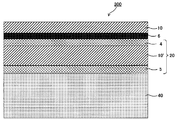
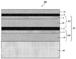
- One embodiment of the present disclosure provides a laminate having the polyimide film of one embodiment of the present disclosure and a hard coat layer containing a radically polymerizable compound and at least one polymer of a cationically polymerizable compound. .
- An embodiment of the present disclosure provides a surface material for a display, which is the polyimide film of the embodiment of the present disclosure or the laminate of the embodiment of the present disclosure.
- one embodiment of the present disclosure is the polyimide film of the one embodiment of the present disclosure or the laminate of the one embodiment of the present disclosure;
- a transparent electrode composed of a plurality of conductive parts disposed on one side of the polyimide film or the laminate;
- a touch panel member is provided having a plurality of lead lines electrically connected on at least one side of an end of the conductive portion.
- one embodiment of the present disclosure is the polyimide film of the one embodiment of the present disclosure or the laminate of the one embodiment of the present disclosure;
- a liquid crystal display device comprising: a liquid crystal display unit having a liquid crystal layer between opposing substrates disposed on one side of the polyimide film or the laminate.
- one embodiment of the present disclosure is the polyimide film of the one embodiment of the present disclosure or the laminate of the one embodiment of the present disclosure;
- An organic electroluminescent display device comprising: an organic electroluminescent display unit having an organic electroluminescent layer between opposing substrates, disposed on one side of the polyimide film or the laminate.
- a resin film having good transparency and durability and reduced optical distortion can be provided.
- a laminate having the resin film, a surface material for a display which is the resin film or the laminate, a touch panel member including the resin film or the laminate, a liquid crystal display device, And an organic electroluminescent display can be provided.
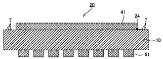
- FIG. 5 is a cross-sectional view of the touch panel member shown in FIG. 2 and FIG.
- FIG. 5 is a cross-sectional view of the touch panel member shown in FIG. 2 and FIG.
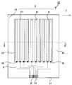
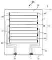
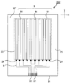
- FIG. 5 is a schematic plan view showing an example of a conductive member provided with a layered product of this indication.
- FIG. 2 is a cross-sectional view of the touch panel member shown in FIG. 2 and FIG.
- FIG. 5 is a schematic plan view showing an example of a conductive member provided with a layered product of this indication.
- It is a schematic sectional drawing which shows another example of the touch-panel member of this indication.
- the polyimide film of one embodiment of the present disclosure has a temperature-loss tangent (tan ⁇ ) curve obtained by dynamic viscoelasticity measurement.
- the maximum value of tan ⁇ in the following temperature range is 0.18 or more,
- the total light transmittance measured in accordance with JIS K7361-1 is 85% or more.
- tan ⁇ in the temperature-loss tangent (tan ⁇ ) curve obtained by dynamic viscoelasticity measurement, tan ⁇ in the temperature range of not less than 500 ° C. and not less than the temperature of the high temperature side minimum value of the first peak where the maximum value is maximum.
- the present inventors examined among the resin films paying attention to a polyimide film derived from its chemical structure and known to be excellent in durability.
- a polyimide film has a problem that optical distortion is large, and especially the phase contrast of a film thickness direction is large.
- Retardation occurs due to the anisotropy of the refractive index.
- the anisotropy of the refractive index generally occurs when the polymer chains in the solid are not randomly present but are oriented regularly.
- Polyimides tend to have more linear molecular structures in polymer chains because there are fewer bendable bond sites in the chemical structure as compared to other resins.
- Such a structure is a factor that can increase the elastic modulus, but it also becomes a factor that makes it easy to fold regularly in a state where the linear molecular structure is oriented in the film thickness direction. It is assumed that the phase difference in the film thickness direction is large.
- the present inventors measured the temperature-loss tangent (tan ⁇ ) curve (hereinafter may be simply referred to as the tan ⁇ curve) obtained by measuring the dynamic viscoelasticity of a polyimide film, and the temperature of the high temperature side minimum value of the first peak. When the maximum value of tan ⁇ in the temperature range of 500 ° C.
- the tan ⁇ is a value obtained by dividing the loss elastic modulus by the storage elastic modulus, and indicates the viscoelastic property of the polymer material.
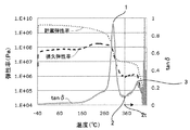
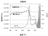
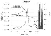
- FIG. 1 shows an example of a tan ⁇ curve, a storage elastic modulus curve, and a loss elastic modulus curve of the polyimide film of the present disclosure.
- the temperature of the maximum value of the first peak (1) at which the maximum value of the tan ⁇ curve is the maximum indicates the glass transition point of the polyimide film.
- the present inventors can obtain a sufficiently reduced retardation with a polyimide film in which the maximum value of tan ⁇ in the first peak high temperature region is 0.18 or more. I found that.
- Temperature-loss tangent (tan ⁇ ) curve The polyimide film of the present disclosure has a temperature-loss tangent (tan ⁇ ) curve obtained by dynamic viscoelasticity measurement.
- the maximum value of tan ⁇ in a temperature range of 0 ° C. or less is 0.18 or more.
- the maximum value of tan ⁇ may be 0.18 or more in the temperature range of not less than the temperature of the high temperature side minimum value of the first peak having the maximum value at the maximum in the tan ⁇ curve and 460 ° C. or less.
- the tan ⁇ curve of the polyimide film of the present disclosure has a first peak whose maximum value is the largest.
- the temperature at the maximum of the first peak indicates the glass transition temperature of the polyimide film.
- the temperature range in which the first peak is present is not particularly limited, but is preferably 400 ° C. or less from the viewpoint of transparency.
- the temperature range in which the first peak is present is preferably 200 ° C. or more, and more preferably 250 ° C. or more.
- the polyimide film of the present disclosure has a temperature range from a temperature (2 t) to 500 ° C. or less at the high temperature side minimum value (2) of the first peak (1) having the maximum value in the tan ⁇ curve.
- the maximum value (3) of tan ⁇ in the above is 0.18 or more.
- the maximum value of tan ⁇ is preferably 0.20 or more, and more preferably 0.21 or more, in order to obtain a further reduced phase difference.
- the upper limit of the maximum value of tan ⁇ is not particularly limited, but is preferably 0.50 or less, and more preferably 0.30 or less.
- the maximum value of tan ⁇ in the temperature range of not less than the temperature of the high temperature side minimum value of the first peak and not more than 500 ° C. is the temperature range of the high temperature side minimum value from the maximum value of the first peak, ie, the decrease of the first peak
- the value of tan ⁇ in the phase is not included.
- the temperature range above the temperature of the high temperature side minimum value of the first peak is 200 ° C. or more and 450 ° C. or less from the relationship with the preferable temperature range in which the first peak exists, ie, the transparency and heat resistance of the polyimide film. Is preferably 250 ° C. or more and 450 ° C. or less, more preferably 300 ° C. or more and 450 ° C.
- the maximum value of the peak may be 0.18 or more; The maximum value of is more preferably 0.20 or more, and still more preferably 0.21 or more.
- the said peak which exists in the temperature range of 500 degreeC or less above the temperature of the high temperature side minimum value of the said 1st peak reduces a phase difference that a maximum value is the 2nd largest 2nd peak in a tan-delta curve.
- the tan ⁇ curve has a first peak having a maximum maximum value, and the second maximum value is 0.18 or more in a temperature range higher than the temperature of the maximum value of the first peak. Having a peak is preferable in terms of reducing the phase difference. Furthermore, the tan ⁇ curve has a second peak with the second largest maximum value in the temperature range of 500 ° C. or less at a temperature higher than the temperature of the high temperature side minimum value of the first peak where the maximum value is the largest.
- the maximum value is preferably 0.18 or more, more preferably 0.20 or more, and still more preferably 0.21 or more.
- the dynamic viscoelasticity measurement is performed as a deformation mode with a measurement range of -40 ° C or more and 500 ° C or less by a dynamic viscoelasticity measurement device RSA-G2 (manufactured by TA Instruments) in a measurement room at 23 ° C and 56% RH.
- the tensile force can be selected, under a nitrogen atmosphere, at a frequency of 1 Hz, a heating rate of 10 ° C./min, a minimum load of 2 g, Axial force> Dynamic Force 1.5%, and Strain 0.1%.
- a test piece prepares length 40 mm, width 5 mm, and can measure the distance between chucks as 20 mm.
- the data is quantified and analyzed from the numerical value.
- the peak of the tan ⁇ curve refers to a peak having an inflection point which is a maximum value and having a peak width of 3 ° C. or more between valleys of the peak and noise etc.
- the fine vertical fluctuation derived from is not interpreted as the above-mentioned peak.
- the polyimide film of the present disclosure has a total light transmittance of 85% or more as measured in accordance with the aforementioned JIS K7361-1. Such high transmittance allows for good transparency and can be a glass substitute material.
- the total light transmittance of the polyimide film of the present disclosure measured according to JIS K7361-1 is preferably 88% or more, more preferably 89% or more, and particularly preferably 90% or more. Is preferred.
- the polyimide film of the present disclosure preferably has a total light transmittance of 85% or more, more preferably 88% or more, measured in accordance with JIS K7361-1 at a thickness of 5 ⁇ m to 100 ⁇ m.
- the polyimide film of the present disclosure preferably has a total light transmittance of 85% or more, more preferably 88% or more, measured at a thickness of 50 ⁇ m ⁇ 5 ⁇ m in accordance with JIS K7361-1. It is more preferably 89% or more, and particularly preferably 90% or more.
- the total light transmittance measured according to JIS K7361-1 can be measured, for example, by a haze meter (for example, HM150 manufactured by Murakami Color Research Laboratory). From the measured value of the total light transmittance of a certain thickness, the converted total light transmittance of different thicknesses can be determined according to the Lambert-Beer's law, which can be used.
- a polyimide is obtained by reacting a tetracarboxylic acid component and a diamine component. After the polyamic acid which is a precursor is obtained by polymerizing a tetracarboxylic acid component and a diamine component, the precursor is imidized. Accordingly, the polyimide used in the present disclosure is one containing a tetracarboxylic acid residue and a diamine residue in the main chain.
- tetracarboxylic acid residue refers to a residue obtained by removing four carboxyl groups from tetracarboxylic acid, and represents the same structure as a residue obtained by removing an acid dianhydride structure from tetracarboxylic acid dianhydride.
- a diamine residue means the residue remove
- the production of the polyimide film may be carried out by a thermal imidization method in which it is molded in the state of a polyimide precursor and then heat treated to form polyimide. It may be carried out by removing the solvent from the solution which has become polyimide (for example, made into polyimide by chemical imidization), or it can also be carried out by a method using the thermal imidization and the chemical imidization in combination. However, among them, it is preferable to manufacture the polyimide film of the present disclosure by a method of forming a polyimide film by heating (thermal imidization) after film formation using a polyimide precursor solution, from the viewpoint of easily reducing retardation.
- polyimide precursors have higher backbone flexibility than polyimides and are more likely to be present irregularly in the film.
- imidation in such a solid phase from the polyimide precursor which exists in such an irregular state even after being made into a polyimide, it is easy to take an irregular structure.
- the phase difference tends to be lower in the method of producing a polyimide film by heating after film formation of the polyimide precursor.
- the polyimide obtained by imidizing a polyimide precursor (polyamic acid) in a solution by chemical imidization has a linear molecular structure due to the reduction of bendable movable parts of the molecular structure during film formation. Cheap.
- the polyimide in the obtained polyimide film is easily folded regularly in a state in which it is oriented in a direction parallel to the film thickness, the intermolecular interaction becomes large and the retardation easily becomes large.
- a method such as polyimide having a flexible skeleton or instantaneously removing the solvent. From such reasons, it is preferable to use thermal imidization in order to make the maximum value of tan ⁇ in the first peak high temperature region within the range of 0.18 or more in the tan ⁇ curve.
- tetracarboxylic acid component to be a tetracarboxylic acid residue
- a tetracarboxylic acid component having an aromatic ring is preferable in terms of improving the surface hardness of the polyimide film.
- tetracarboxylic acid dianhydride having an aromatic ring for example, pyromellitic acid dianhydride, 3,3 ′, 4,4′-benzophenonetetracarboxylic acid dianhydride 2,2 ', 3,3'-benzophenonetetracarboxylic dianhydride, 3,3', 4,4'-biphenyltetracarboxylic dianhydride, 2,2 ', 3,3'-biphenyltetracarboxylic acid Acid dianhydride, 2,2-bis (3,4-dicarboxyphenyl) propane dianhydride, 2,2-bis (2,3-dicarboxyphenyl) propane dianhydride, bis (3,4-di Carboxyphenyl) ether dianhydride, bis (3,4-dicarboxyphenyl) sulfone dianhydride, 1,1-bis (2,3-dicarboxypheny
- the tetracarboxylic acid component which has an aliphatic ring is also preferable from the point of the light transmittance of a polyimide film.
- tetracarboxylic acid dianhydrides having an aliphatic ring include cyclohexanetetracarboxylic acid dianhydride, cyclopentanetetracarboxylic acid dianhydride, dicyclohexane-3,4,3 ′, 4′-tetracarboxylic acid Anhydride, cyclobutane tetracarboxylic acid dianhydride, etc. are mentioned.
- the tetracarboxylic acid component mentioned above can also be used individually or in mixture of 2 or more types.
- the diamine which has an aromatic ring for example is preferable from the point of durability of a polyimide film, and surface hardness.
- the diamine which has an aliphatic ring is also preferable from the point of the light transmittance of a polyimide film.
- the polyimide film which concerns on this indication contains the polyimide which contains the diamine residue which has a silicon atom in a principal chain especially.
- the silicon atom portion can be in a bent structure, so it is easy to obtain a polyimide having a polymer chain containing a more bent molecular structure. It is preferable from the point which is easy to obtain.
- diamine having an aromatic ring for example, 4,4′-diaminodiphenyl sulfone, 3,4′-diaminodiphenyl sulfone, 2,2-bis (4-aminophenyl) propane, 2,2-bis (4-bis (4-aminophenyl) propane) Aminophenyl) hexafluoropropane, p-phenylenediamine, o-phenylenediamine, 3,4'-diaminodiphenyl ether, 4,4'-diaminodiphenyl ether, 3,4'-diaminodiphenyl sulfide, 4,4'-diaminodiphenyl sulfide 4,4'-Diaminobenzophenone, 3,4'-diaminobenzophenone, 4,4'-diaminobenzanilide, 4,4'-diaminodiphenylmethane, 3,4'-diamino
- diamine having an aliphatic ring examples include trans-cyclohexanediamine, trans-1,4-bismethylenecyclohexanediamine, 2,6-bis (aminomethyl) bicyclo [2,2,1] heptane, 2,5- Bis (aminomethyl) bicyclo [2,2,1] heptane and the like can be mentioned.
- diamine which has a silicon atom in a principal chain
- diamine represented by the following general formula (A) is mentioned, for example.
- each L independently represents a direct bond or an -O- bond
- each R 10 independently represents a substituent, and may contain an oxygen atom or a nitrogen atom
- R 11 independently represents a monovalent hydrocarbon group having 1 to 20 carbon atoms which may be substituted, and R 11 may independently have a substituent, and may contain an oxygen atom or a nitrogen atom
- k is a number of 0 to 200.
- a plurality of L, R 10 and R 11 may be the same or different from each other)
- the alkyl group may be linear, branched or cyclic, and may be linear or a combination of branched and cyclic.
- the alkyl group having 1 to 20 carbon atoms is preferably an alkyl group having 1 to 10 carbon atoms, and specifically, a methyl group, an ethyl group, a propyl group, an isopropyl group, a butyl group, an isobutyl group, Examples thereof include t-butyl group, pentyl group and hexyl group.
- the cyclic alkyl group is preferably a cycloalkyl group having 3 to 10 carbon atoms, and specific examples thereof include a cyclopentyl group and a cyclohexyl group.
- the aryl group is preferably an aryl group having 6 to 12 carbon atoms, and specific examples thereof include a phenyl group, a tolyl group and a naphthyl group.
- the monovalent hydrocarbon group represented by R 10 may be an aralkyl group, and examples thereof include a benzyl group, a phenylethyl group and a phenylpropyl group.
- hydrocarbon group which may contain an oxygen atom or a nitrogen atom
- examples of the hydrocarbon group which may contain an oxygen atom or a nitrogen atom include, for example, an ether bond, a carbonyl bond, an ester bond, an amide bond, and an imino bond between a divalent hydrocarbon group described later and the monovalent hydrocarbon group. Included is a group bonded via at least one of the bonds (—NH—).
- the substituent which the monovalent hydrocarbon group represented by R 10 may have is not particularly limited as long as the effects of the present disclosure are not impaired, and for example, a halogen atom such as a fluorine atom or a chlorine atom And hydroxyl groups.
- the monovalent hydrocarbon group represented by R 10 is an alkyl group having 1 to 3 carbon atoms or an aryl group having 6 to 10 carbon atoms from the viewpoint of improving bending resistance and compatibility with surface hardness. Is preferred.
- the alkyl group having 1 to 3 carbon atoms is more preferably a methyl group, and the aryl group having 6 to 10 carbon atoms is more preferably a phenyl group.
- the alkylene group may be linear, branched or cyclic, and may be linear or a combination of branched and cyclic.
- the alkylene group having 1 or more and 20 or less carbon atoms is preferably an alkylene group having 1 or more and 10 or less carbon atoms, and for example, a straight chain such as methylene group, ethylene group, various propylene groups, various butylene groups and cyclohexylene groups Examples include groups in combination of linear or branched alkylene groups and cyclic alkylene groups.
- the arylene group is preferably an arylene group having a carbon number of 6 to 12, and examples of the arylene group include a phenylene group, a biphenylene group, and a naphthylene group, and further have a substituent for the aromatic ring described later.
- the divalent hydrocarbon group which may contain an oxygen atom or a nitrogen atom include an ether bond, a carbonyl bond, an ester bond, an amide bond, and an imino bond (-NH-) between the above-mentioned divalent hydrocarbon groups. At least one bonded group is mentioned.
- the substituent which the divalent hydrocarbon group represented by R 11 may have is the same as the substituent which the monovalent hydrocarbon group represented by R 10 may have. It is good.
- the divalent hydrocarbon group represented by R 11 is an alkylene group having 1 to 6 carbon atoms, or an arylene group having 6 to 10 carbon atoms, from the viewpoint of improving bending resistance and compatibility with surface hardness. It is more preferable that it is an alkylene group having 2 to 4 carbon atoms.
- a diamine residue having a silicon atom in the main chain is a diamine residue having one or two silicon atoms in the main chain, from the viewpoint of achieving low retardation and improving the compatibility of bending resistance and surface hardness. It is preferably a group.
- the number of silicon atoms in the main chain of the diamine residue is not particularly limited, but is preferably one or two, and more preferably two. When the number of silicon atoms is 3 or more, the effect for realizing low retardation is saturated, and the flexibility of the polyimide is too high, which may affect the heat resistance.
- diamines having one silicon atom in the main chain examples include diamines represented by the following general formula (A-1). Further, examples of the diamine having two silicon atoms in the main chain include diamines represented by the following general formula (A-2).
- L is each independently a direct bond or -O- bond, and each R 10 independently has a substituent Or a monovalent hydrocarbon group having 1 to 20 carbon atoms which may contain an oxygen atom or a nitrogen atom, and each R 11 may independently have a substituent, and an oxygen atom Or a divalent hydrocarbon group having 1 to 20 carbon atoms which may contain a nitrogen atom, and a plurality of L, R 10 and R 11 may be identical to or different from each other)
- the molecular weight of the diamine residue having a silicon atom in the main chain is preferably 1,000 or less, more preferably 800 or less, and still more preferably 500 or less. Preferably, it is 300 or less.
- the molecular weight of the diamine residue is calculated by subtracting the molecular weight (32) of two amino groups (-NH 2 ) from the molecular weight of the diamine.
- the diamine residue which has a silicon atom in a principal chain can also be used individually or in mixture of 2 or more types.
- the diamine having one or two silicon atoms in the main chain is a diamine having two silicon atoms from the viewpoint of light transmittance of the resulting polyimide, and in terms of bending resistance and surface hardness, Furthermore, 1,3-bis (3-aminopropyl) tetramethyldisiloxane, 1,3-bis (4-aminobutyl) tetramethyldisiloxane, 1,3-bis (5-aminopentyl) tetramethyldisiloxane, etc. However, it is preferable from the viewpoints of the availability of these compounds and the light transmittance and surface hardness of the resulting polyimide.
- the ratio of the diamine having a silicon atom in the main chain to the total amount of diamine is not particularly limited, but from the viewpoint of reducing the retardation of the obtained polyimide film, 1 It is preferable that it is mol% or more, It is more preferable that it is 2.5 mol% or more, It is still more preferable that it is 5 mol% or more. Also, from the viewpoint of the heat resistance of the polyimide film to be obtained, it is preferably 50 mol% or less, more preferably 45 mol% or less, more preferably 40 mol% or less, and 20 mol% or less. Even more preferred is
- the total amount of the tetracarboxylic acid component and the diamine component is 100 mol%
- the total of the tetracarboxylic acid having an aromatic ring and the diamine having an aromatic ring is It is preferably 50 mol% or more, more preferably 60 mol% or more, and still more preferably 75 mol% or more.
- the polyimide may contain an aromatic ring, and (i) a fluorine atom, (ii) an aliphatic ring, and (iii) an aromatic ring may be substituted with a sulfonyl group or fluorine. It is preferable from the viewpoint of light transmittance and surface hardness that it contains at least one selected from the group consisting of an alkylene group-linked structure, and further, in addition to these structures, a diamine residue having a silicon atom in the main chain It is preferable to include a group from the viewpoint of low retardation and flex resistance.
- the polyimide when the polyimide contains at least one selected from a tetracarboxylic acid residue having an aromatic ring and a diamine residue having an aromatic ring, the molecular skeleton becomes rigid and the durability is enhanced, and the surface hardness is improved.
- the rigid aromatic ring skeleton tends to extend the absorption wavelength to a long wavelength, and the transmittance in the visible light range tends to decrease.
- the polyimide contains (i) a fluorine atom, the light transmission is improved because the charge transfer of the electronic state in the polyimide skeleton can be made difficult.
- the light transmission is improved from the point of being able to inhibit the movement of charges in the skeleton by breaking the conjugation of ⁇ electrons in the polyimide skeleton.
- the polyimide has a structure in which (iii) aromatic rings are linked by an alkylene group which may be substituted with a sulfonyl group or a fluorine group, the charge transfer in the skeleton is broken by breaking the conjugation of ⁇ electrons in the polyimide skeleton. The light transmission is improved because it can be inhibited.
- a polyimide containing a fluorine atom is preferably used from the viewpoint of improving the light transmittance and the surface hardness.
- the content ratio of fluorine atoms is preferably such that the ratio (F / C) of the number of fluorine atoms (F) to the number of carbon atoms (C) when the polyimide surface is measured by X-ray photoelectron spectroscopy is 0.01 or more Furthermore, it is preferable that it is 0.05 or more.
- the ratio (F / C) of the number of fluorine atoms (F) to the number of carbon atoms (C) is 1 or less Is preferably, and further preferably 0.8 or less.
- the above ratio by the measurement of X-ray photoelectron spectroscopy (XPS) can be determined from the value of atomic% of each atom measured using an X-ray photoelectron spectrometer (for example, Theta Probe, manufactured by Thermo Scientific) .
- a tetracarboxylic acid and a diamine not having a silicon atom contains an aromatic ring and a fluorine atom. Furthermore, it is preferred that both the tetracarboxylic acid and the diamine not having a silicon atom contain an aromatic ring and a fluorine atom.
- a tetracarboxylic acid having an aromatic ring and a fluorine atom when the total amount of the tetracarboxylic acid component and the diamine component is 100 mol%, from the viewpoint of surface hardness and light transmittance of the obtained polyimide and the point of bending resistance.
- the total amount of the diamine having an aromatic ring and a fluorine atom is preferably 50 mol% or more, more preferably 60 mol% or more, and still more preferably 75 mol% or more.
- the light transmittance of the resulting polyimide is improved in that at least 50% of the hydrogen atoms bonded to carbon atoms contained in the tetracarboxylic acid component and the diamine component are hydrogen atoms directly bonded to the aromatic ring. And from the viewpoint of improving surface hardness and bending resistance.
- the percentage of hydrogen atoms (number) directly bonded to the aromatic ring in all hydrogen atoms (number) bonded to carbon atoms is preferably 60% or more, more preferably 70% or more .
- the ratio of hydrogen atoms (number) directly bonded to the aromatic ring in all hydrogen atoms (number) in carbon atoms contained in the polyimide is high-performance liquid chromatography, gas chromatography mass of polyimide decomposition product It can be determined using an analyzer and NMR.
- the sample is decomposed by an aqueous alkaline solution or supercritical methanol, and the resulting decomposition product is separated by high performance liquid chromatography, and the qualitative analysis of each separated peak is performed by gas chromatography mass spectrometry, NMR, etc.
- the ratio of hydrogen atoms (number) directly bonded to the aromatic ring in all hydrogen atoms (number) in the polyimide can be determined by performing measurement using high performance liquid chromatography.
- the polyimide film which concerns on this indication contains the polyimide which has a structure represented by following General formula (1) from the point of light transmittance, heat resistance, and rigidity.
- R 1 represents a tetravalent group which is a tetracarboxylic acid residue having an aromatic ring or an aliphatic ring
- R 2 represents a divalent group which is the diamine residue.
- n represents the number of repeating units
- tetracarboxylic dianhydride having an aromatic ring in R 1 and the tetracarboxylic dianhydride having an aliphatic ring those similar to the above can be used. These may be used alone or in combination of two or more.
- R 1 in the general formula (1) is a residue of cyclohexanetetracarboxylic acid dianhydride, cyclopentanetetracarboxylic acid, from the viewpoint of light transmittance in the polyimide to be obtained, and bending resistance and surface hardness.
- Anhydride residue Dicyclohexane-3,4,3 ′, 4′-tetracarboxylic acid dianhydride residue, cyclobutanetetracarboxylic acid dianhydride residue, pyromellitic acid dianhydride residue, 3,3 ′ 1,4,4'-biphenyltetracarboxylic acid dianhydride residue, 2,2 ', 3,3'-biphenyltetracarboxylic acid dianhydride residue, 4,4'-(hexafluoroisopropylidene) diphthalic anhydride Residue, 3,4 '-(hexafluoroisopropylidene) diphthalic anhydride residue, 3,3'-(hexafluoroisopropylidene) diphthalic anhydride residue, 4,4'-oxydiphthalic acid Anhydride residue, and is preferably at least one tetravalent group selected from the group consisting of 3,4'-oxydiphthalic anhydride residue.
- the tetracarboxylic acid component is particularly preferably 4,4 '-(hexafluoroisopropylidene) diphthalic anhydride, 3,4'-(hexafluoroisopropylidene) diphthalic anhydride, and 3,3 from the viewpoint of good light transmittance. More preferably, it is at least one selected from the group consisting of '-(hexafluoroisopropylidene) diphthalic anhydride, 4,4'-oxydiphthalic anhydride, and 3,4'-oxydiphthalic anhydride.
- Tetracarboxylic acid group (group A) suitable for improving the rigidity of the resulting polyimide such as at least one member selected from the group consisting of: cyclohexane tetracarboxylic acid dianhydride, cyclopentane tetracarbon Acid dianhydride, dicyclohexane-3,4,3 ′, 4′-tetracarboxylic acid dianhydride, cyclobutanetetracarboxylic acid dianhydride, 4,4 ′-(hexafluoroisopropylidene) diphthalic acid anhydride, 3 4,4 '-(hexafluoroisopropylidene) diphthalic
- the content ratio of the tetracarboxylic acid group (group A) suitable for improving the rigidity and the tetracarboxylic acid group (group B) suitable for improving the light transmittance is the light transmittance.
- At least one of 4,4 '-(hexafluoroisopropylidene) diphthalic anhydride and 3,4'-(hexafluoroisopropylidene) diphthalic anhydride containing a fluorine atom is used as the group B. It is preferable from the point of the improvement of the light transmittance in the polyimide obtained.
- R 2 represents a divalent group which is a diamine residue, and is not particularly limited as long as it contains a diamine residue having an aromatic ring or an aliphatic ring.
- a bivalent diamine residue the thing similar to the above can be used. These may be used alone or in combination of two or more.
- diamine residue having an aromatic ring or an aliphatic ring contained in R 2 may each, using the same as those described above. These may be used alone or in combination of two or more.
- the diamine residue having an aromatic ring or an aliphatic ring in R 2 in the general formula (1) is trans-, from the viewpoint of light transmittance, bending resistance, surface hardness and low hygroscopicity.
- R 3 and R 4 each independently represent a hydrogen atom, an alkyl group or a perfluoroalkyl group.
- diamine residue having a silicon atom in the main chain is included as R 2. Since the diamine residue which has a silicon atom in the principal chain which can be preferably used as R 2 is as described above, the description is omitted here.
- R 2 in the general formula (1) When containing a diamine residue having a silicon atom in the main chain as R 2 in the general formula (1), in R 2 in the general formula (1), 2.5 mol% to 50 mol of the total amount of R 2 % Or less is a diamine residue having a silicon atom in the main chain, and 50 to 97.5 mol% of the total amount of R 2 has no silicon atom and has an aromatic ring or an aliphatic ring By being a diamine residue, retardation is reduced and surface hardness sufficient as a protective film can be obtained, which is preferable.
- R 2 in the general formula (1) is preferably a diamine residue having a silicon atom in the main chain is 3.5 mol% or more of the total amount of R 2 , and more preferably 5 It is preferable that it is mol% or more.
- R 2 in the general formula (1) from the point where the phase difference is reduced, the diamine residue having a silicon atom in the main chain, 10 mol% or more of the total amount of R 2, even more than 20 mol% good.
- R 2 in the general formula (1) is that the diamine residue having a silicon atom in the main chain is 45 mol% or less of the total amount of R 2 from the viewpoint of improving surface hardness and light transmittance.
- it is more preferably 40 mol% or less.
- the other diamine residue is preferably 10 mol% or less, more preferably 5 mol% or less, still more preferably 3 mol% or less, and particularly preferably 1 mol% or less of the total amount of R 2 It is preferable that it is the following.
- the diamine residue etc. which do not have a silicon atom and do not have an aromatic ring or an aliphatic ring are mentioned, for example.
- a diamine residue having a silicon atom in the main chain of the total amount of R 2 (100 mol%), silicon atoms in the main chain
- the remaining (100% -x%) of the remaining (100% -x%) of the mole% (x mole%) of the diamine residue having 50 has no silicon atom and has an aromatic ring or an aliphatic ring It is preferable that it is a diamine residue.
- R 2 in the general formula (1) is a diamine residue having no silicon atom, and silicon in the main chain, from the viewpoint of reducing retardation and achieving a balance between bending resistance and surface hardness.
- 50 mole% 2.5 mol% or more of the total amount of R 2 or less is a main one silicon atom in a chain or two with diamine residue, of the total amount of R 2 (100 mol%), the 50 mol% or more and 97.5 mol% or less, which is the remainder (100% -x%) of the mol% (x mol%) of the diamine residue having one or two silicon atoms in the main chain has a silicon atom
- it is a diamine residue having an aromatic ring or an aliphatic ring.
- R 2 in the general formula (1) has 3 or less of the total amount of R 2 diamine residues having one or two silicon atoms in the main chain.
- the diamine residue having no silicon atom and having an aromatic ring or an aliphatic ring corresponds to the above, R 2 It is preferable that it is 97 mol% or less of the total of, and still more preferable that it is 95 mol% or less.
- R 2 in the general formula (1) from the point where the phase difference is reduced, diamine residue having one or two silicon atoms in the main chain, at least 10 mole% of the total amount of R 2, further 20 mol%
- the diamine residue having no silicon atom and having an aromatic ring or an aliphatic ring is 90 mol% or less, and further 80 mol or less of the total amount of R 2 corresponding to the above. It may be less than%.
- R 2 in the general formula (1) has a diamine residue having one or two silicon atoms in the main chain from the viewpoint of improving surface hardness and light transmittance while reducing retardation.
- Te is preferably at least 55 mol% of the total amount of R 2, is preferably more further 60 mol% or more.
- n represents the number of repeating units and is 1 or more.
- the number n of repeating units in the polyimide may be appropriately selected, and is not particularly limited.
- the average number of repeating units is usually 10 to 2,000, preferably 15 to 1,000.
- R 1 in each repeating unit may be the same or different, and R 2 in each repeating unit may be the same or different.
- the polyimide having a structure represented by the general formula (1) preferably has a number average molecular weight of 10000 or more, more preferably 20000 or more, from the viewpoint of strength and bending resistance when formed into a film. Preferably, it is more preferably 30000 or more, and particularly preferably 50000 or more.
- the upper limit is not particularly limited, but is preferably 10,000,000 or less, more preferably 500,000 or less, from the viewpoint of easy synthesis and easy availability.
- the number average molecular weight of the polyimide can be measured in the same manner as the number average molecular weight of the polyimide precursor described later.
- the polyimide having the structure represented by the general formula (1) preferably has a weight average molecular weight of 20000 or more, and 30000 or more, from the viewpoint of strength and bending resistance when formed into a film. More preferably, it is 40000 or more, still more preferably 80000 or more.
- the upper limit is not particularly limited, but is preferably 10,000,000 or less, more preferably 500,000 or less, from the viewpoint of easy synthesis and easy availability.
- the weight average molecular weight of the polyimide can be measured by gel permeation chromatography (GPC).
- polyimide is used as an N-methyl pyrrolidone (NMP) solution with a concentration of 0.1% by weight, and a developing solvent is a 30 mmol% LiBr-NMP solution with a water content of 500 ppm or less.
- NMP N-methyl pyrrolidone
- a developing solvent is a 30 mmol% LiBr-NMP solution with a water content of 500 ppm or less.
- the weight average molecular weight is determined based on a polystyrene standard sample at the same concentration as the sample.
- the polyimide used in the present disclosure may have a structure different from the polyimide in a part thereof, such as a polyamide structure, as long as the effects of the present disclosure are not impaired.
- the polyimide used for this indication may have a structure different from the structure represented by the said General formula (1) in the one, unless the effect of this indication is impaired.
- the structure represented by the general formula (1) is preferably 95% or more, more preferably 98% or more, and more preferably 100% of the total number of repeating units of the polyimide. Even more preferred is As a structure different from the structure represented by the said General formula (1), the case where the tetracarboxylic-acid residue etc.
- polyamide structure which do not have an aromatic ring or an aliphatic ring etc. are contained, for example, and a polyamide structure are mentioned.
- the polyamide structure which may be contained include a polyamideimide structure containing a tricarboxylic acid residue such as trimellitic anhydride, and a polyamide structure containing a dicarboxylic acid residue such as terephthalic acid.
- the content ratio of each repeating unit in the polyimide, and the content ratio (mol%) of each tetracarboxylic acid residue and each diamine residue can be determined from the molecular weight of the feed at the time of polyimide production.
- the content ratio (mol%) of each tetracarboxylic acid residue and each diamine residue in the polyimide is the decomposition product of the polyimide obtained by decomposition with an alkaline aqueous solution or supercritical methanol as described above.
- the polyimide film of the present disclosure may further contain an additive, if necessary, in addition to the polyimide.
- the additive include inorganic particles, a silica filler for facilitating winding, and a surfactant for improving film forming properties and defoaming properties.
- the phase difference is reduced. Since the measured value of the retardation is affected by the film thickness, it may not be possible to evaluate the superiority or inferiority of the retardation of the polyimide film only by the measured value. Therefore, it is usually calculated by dividing the retardation by the film thickness. Convert to refractive index and evaluate.
- the birefringence in the film thickness direction at a wavelength of 590 nm is preferably smaller, and more preferably less than 0.008, and still more preferably 0.005 or less. It is even more preferable that it is 004 or less.
- the retardation in the film thickness direction at a wavelength of 590 nm and the birefringence of the polyimide film of the present disclosure can be determined as follows. First, a retardation value (Rth) in the film thickness direction of a polyimide film is measured with light at a wavelength of 590 nm at 25 ° C. using a retardation measurement apparatus (for example, product name “KOBRA-WR” manufactured by Oji Scientific Instruments Co., Ltd.) taking measurement.
- a retardation measurement apparatus for example, product name “KOBRA-WR” manufactured by Oji Scientific Instruments Co., Ltd.
- the film thickness direction retardation value (Rth) measures a retardation value at 0 degree incidence and a retardation value at 40 degree oblique incidence, and calculates a film thickness direction retardation value Rth from these retardation values.
- the retardation value of the oblique 40-degree incidence is measured by causing light of wavelength 590 nm to be incident on the retardation film from a direction inclined 40 degrees from the normal of the retardation film.
- the birefringence in the film thickness direction of the polyimide film can be determined by substituting it into the formula: Rth / d. Said d represents the film thickness (nm) of a polyimide film.
- the refractive index of the slow axis direction in the in-plane direction of the film (the direction in which the refractive index in the film in-plane direction is maximum) is nx
- the polyimide film of the present disclosure preferably has a yellowness (YI value) of 30 or less calculated in accordance with JIS K7373-2006.
- the yellowness (YI value) calculated in accordance with JIS K7373-2006 is preferably 20 or less, more preferably 15 or less, and still more preferably 10 or less.
- the polyimide film of the present disclosure preferably has a yellowness (YI value) calculated according to JIS K7373-2006 at a thickness of 5 ⁇ m to 100 ⁇ m, preferably 30 or less, and more preferably 20 or less.
- the polyimide film of the present disclosure preferably has a yellowness (YI value) of 10 or less, preferably 7 or less, at a thickness of 50 ⁇ m ⁇ 5 ⁇ m, which is calculated according to the aforementioned JIS K7373-2006. Preferably, it is 5 or less.
- the degree of yellowness (YI value) can be determined by the spectrophotometric method using an ultraviolet visible near infrared spectrophotometer (for example, JASCO Corporation V-7100) in accordance with JIS K7373-2006.
- tristimulus values X, Y, Z in the XYZ color system are determined based on the transmittance measured at 1 nm intervals in the range of 250 nm or more and 800 nm or less using a 2 ° field of view, and the X, Y, Z It can be calculated from the value of Z according to the following equation.
- the degree of yellowness of a different thickness is the total of the respective transmittances at each wavelength measured at 1 nm intervals between 250 nm and 800 nm or less of the sample of a specific thickness Similar to the light transmittance, a converted value of each transmittance at each wavelength of different thickness can be obtained according to the Lambert-Beer's law, and it can be calculated and used based on it.
- the haze value of the polyimide film of the present disclosure is preferably 2.0 or less, more preferably 1.5 or less, and still more preferably 1.0 or less from the viewpoint of light transmittance.
- the haze value can preferably be achieved when the thickness of the polyimide film is 5 ⁇ m or more and 100 ⁇ m or less.
- the haze value can be measured by a method according to JIS K-7105, and can be measured, for example, by a haze meter HM150 manufactured by Murakami Color Research Laboratory.
- the polyimide film of the present disclosure measures 15 mm ⁇ 40 mm test pieces in accordance with JIS K7127, and the tensile modulus at 25 ° C. measured at a tensile speed of 8 mm / min and a distance between chucks of 20 mm is the surface hardness. It is preferably 1.8 GPa or more, and may be 5.0 GPa or less from the viewpoint of bending resistance. From the viewpoint of bending resistance and surface hardness, it is more preferable that the energy density be 2.0 GPa or more and 4.0 GPa or less, and still more preferable that the energy density be 2.0 GPa or more and 3.5 GPa or less.
- the tensile modulus is measured at 25 ° C.
- the polyimide film at the time of obtaining the tensile elastic modulus preferably has a thickness of 55 ⁇ m ⁇ 5 ⁇ m.
- the pencil hardness may be 6 B or more, but it is more preferably B or more, and even more preferably HB or more from the viewpoint of surface hardness.
- the pencil hardness of the polyimide film is adjusted according to JIS K 5600-5-4 using a test pencil specified in JIS-S-6006 after conditioning the measurement sample under the conditions of temperature 25 ° C. and relative humidity 60% for 2 hours. It can carry out by performing the pencil hardness test (0. 98N load) prescribed in (1999) on the film surface and evaluating the highest pencil hardness which does not get damaged.
- a tester for example, a pencil scratching film hardness tester manufactured by Toyo Seiki Co., Ltd. can be used.
- the thickness of the polyimide film of the present disclosure may be appropriately selected depending on the application, it is preferably 1 ⁇ m or more, more preferably 5 ⁇ m or more, and still more 10 ⁇ m or more from the viewpoint of strength. Is preferred.
- the polyimide film of the present disclosure may be subjected to surface treatment such as saponification treatment, glow discharge treatment, corona discharge treatment, ultraviolet treatment, flame treatment, and the like.
- the method for producing the polyimide film of the present disclosure is not particularly limited as long as it can produce the polyimide film of the present disclosure, but, for example, as described above, heating the polyamic acid which is a polyimide precursor It is preferable that it is the method of imidating by this, and the following 1st manufacturing method is preferable.
- a first production method Preparing a polyimide precursor resin composition containing a polyamic acid which is a polyimide precursor and an organic solvent (hereinafter referred to as a polyimide precursor resin composition preparation step); Applying the polyimide precursor resin composition to a support to form a polyimide precursor resin coating film (hereinafter referred to as a polyimide precursor resin coating film forming step); And a step of imidizing the polyimide precursor by heating (hereinafter referred to as a thermal imidization step).
- a step of stretching at least one of the polyimide precursor resin coating film and the post-imidized coating film obtained by imidizing the polyimide precursor resin coating film (hereinafter, stretching It may have a process).
- stretching It may have a process.
- a polyimide precursor resin composition contains a polyimide precursor and an organic solvent, and may contain an additive etc. if needed.
- the polyimide precursor represented by following General formula (1 ') is mentioned, for example.
- the polyimide precursor represented by the general formula (1 ′) is a tetracarboxylic acid component to be a tetracarboxylic acid residue in R 1 of the general formula (1 ′), and R 2 of the general formula (1 ′) Is a polyamic acid obtained by polymerization with a diamine component to be a diamine residue.
- the polyimide precursor represented by the general formula (1 ′) preferably has a number average molecular weight or weight average molecular weight of at least 10000 in terms of strength when formed into a film, and more preferably 20000. It is preferable that it is more than. On the other hand, if the average molecular weight is too large, the viscosity will be high, and there is a possibility that the workability such as filtration may be reduced, so it is preferably 10,000,000 or less, more preferably 500,000 or less.
- the number average molecular weight of the polyimide precursor can be determined by NMR (for example, AVANCE III manufactured by BRUKER). For example, after applying a polyimide precursor solution to a glass plate and drying at 100 ° C.
- the number average molecular weight can be calculated from the peak intensity ratio of hydrogen atoms.
- the weight average molecular weight of the polyimide precursor can be measured by gel permeation chromatography (GPC).
- a polyimide precursor is N-methyl pyrrolidone (NMP) solution with a concentration of 0.5% by weight
- a developing solvent is a Tosoh GPC apparatus (HLC-8120, using a 10 mmol% LiBr-NMP solution with a water content of 500 ppm or less)
- HPC-8120 N-methyl pyrrolidone
- the polyimide precursor solution can be obtained by reacting the above-described tetracarboxylic acid dianhydride and the above-described diamine in a solvent.
- the solvent used for synthesis of the polyimide precursor is not particularly limited as long as it can dissolve the above-described tetracarboxylic acid dianhydride and diamine, and, for example, an aprotic polar solvent or a water-soluble alcohol solvent etc. It can be used.
- N-methyl-2-pyrrolidone N, N-dimethylformamide, N, N-dimethylacetamide, dimethylsulfoxide, hexamethylphosphoramide, 1,3-dimethyl-2-imidazolidinone and the like
- organic solvent containing a nitrogen atom of: ⁇ -butyrolactone or the like it is preferable to use an organic solvent containing a nitrogen atom of: ⁇ -butyrolactone or the like.
- the polyimide precursor solution polyamic acid solution
- the dissolution of inorganic particles is suppressed when the polyimide precursor resin composition contains inorganic particles described later.
- an organic solvent containing a nitrogen atom it is preferable to use an organic solvent containing a nitrogen atom, and it is preferable to use N, N-dimethylacetamide, N-methyl-2-pyrrolidone or a combination thereof.
- an organic solvent is a solvent containing a carbon atom.
- an acid dianhydride may be added to the mixed solution of at least 2 types of diamine, and a polyamic acid may be synthesize
- An amic acid in which a diamine having a silicon atom at the main chain at both ends of the anhydride is reacted is synthesized, into which the remaining diamine is fully or partially introduced, and an acid dianhydride is added to polymerize the polyamic acid. Also good.
- diamines having a silicon atom in the main chain are introduced into the polyamic acid in a linked form via one acid dianhydride. It is preferable to polymerize the polyamic acid by such a method because it is specified to some extent in the positional relationship of the amic acid having a silicon atom in the main chain, and a film with low retardation can be easily obtained while maintaining the surface hardness.
- Y / X should be 0.9 or more and 1.1 or less. Preferably, it is more preferably 0.95 or more and 1.05 or less, still more preferably 0.97 or more and 1.03 or less, and particularly preferably 0.99 or more and 1.01 or less.
- the molecular weight (polymerization degree) of the polyamic acid obtained by setting it as such a range can be adjusted moderately.
- the procedure of the polymerization reaction can be selected appropriately from known methods, and is not particularly limited. Alternatively, the polyimide precursor solution obtained by the synthesis reaction may be used as it is, and if necessary, other components may be mixed, or the solvent of the polyimide precursor solution may be dried and dissolved in another solvent. You may use.
- the viscosity at 25 ° C. of the polyimide precursor solution is preferably 500 cps or more and 200,000 cps or less from the viewpoint of forming a uniform coating film and polyimide film.
- the viscosity of the polyimide precursor solution can be measured at 25 ° C. using a viscometer (eg, TVE-22HT, Toki Sangyo Co., Ltd.).
- the said polyimide precursor resin composition may contain the additive as needed.
- the additive include a silica filler for facilitating winding, a surfactant for improving the film forming property and the defoaming property, and the like, and the same as those described in the above-mentioned polyimide film Can be used.
- the organic solvent used for the polyimide precursor resin composition is not particularly limited as long as the polyimide precursor can be dissolved.
- it contains a nitrogen atom such as N-methyl-2-pyrrolidone, N, N-dimethylformamide, N, N-dimethylacetamide, dimethylsulfoxide, hexamethylphosphoramide, 1,3-dimethyl-2-imidazolidinone and the like
- Organic solvents; ⁇ -butyrolactone etc. can be used, but among them, it is preferable to use an organic solvent containing a nitrogen atom for the reason described above.
- the content of the polyimide precursor in the polyimide precursor resin composition is 50% by mass or more in the solid content of the resin composition from the viewpoint of forming a uniform coating film and a polyimide film having a handleable strength.
- the content is preferably 60% by mass or more, and the upper limit may be appropriately adjusted depending on the ingredients.
- the organic solvent in the polyimide precursor resin composition is preferably 40% by mass or more, and more preferably 50% by mass or more in the resin composition, from the viewpoint of forming a uniform coating film and polyimide film. It is preferably 99% by mass or less.
- the storage stability of a polyimide precursor resin composition becomes favorable that the said polyimide precursor resin composition is 1000 ppm or less from the point which can improve productivity.
- the polyimide precursor resin composition contains a large amount of water, the polyimide precursor may be easily decomposed.
- the water content of the polyimide precursor resin composition can be determined using a Karl-Fisher moisture meter (for example, a trace water content measuring device CA-200 type manufactured by Mitsubishi Chemical Co., Ltd.).
- the viscosity at 25 ° C. of a solid content of 15% by mass at a solid content of the polyimide precursor resin composition is preferably 500 cps or more and 100,000 cps or less from the viewpoint of forming a uniform coating film and polyimide film.
- the viscosity of the polyimide precursor resin composition can be measured as a sample volume of 0.8 mL at 25 ° C. using a viscometer (for example, TVE-22HT, Toki Sangyo Co., Ltd.).
- the surface is smooth and heat resistant as a support to be used.
- the material is not particularly limited as long as it is a material having resistance and solvent resistance.
- an inorganic material such as a glass plate, a metal plate whose surface is mirror-finished, and the like can be mentioned.
- the shape of the support is selected depending on the coating method, and may be, for example, a plate, a drum, a belt, a sheet which can be wound on a roll, or the like.
- the application means is not particularly limited as long as it can be applied with a target film thickness, and for example, known means such as die coater, comma coater, roll coater, gravure coater, curtain coater, spray coater, lip coater can be used .
- the application may be performed by a sheet-fed application apparatus or a roll-to-roll application apparatus.
- the solvent in the coating is dried at a temperature of 150 ° C. or less, preferably 30 ° C. or more and 120 ° C. or less until the coating becomes tack-free.
- the drying temperature of the solvent is set to 150 ° C. or less, imidization of the polyamic acid can be suppressed.
- the drying time may be appropriately adjusted depending on the film thickness of the polyimide precursor resin coating film, the type of solvent, the drying temperature and the like, but it is usually 1 minute to 60 minutes, preferably 2 minutes to 30 minutes. When it exceeds the upper limit value, it is not preferable from the viewpoint of the production efficiency of the polyimide film. On the other hand, if the lower limit value is exceeded, rapid drying of the solvent may affect the appearance and the like of the obtained polyimide film.
- the method for drying the solvent is not particularly limited as long as the solvent can be dried at the above temperature, and it is possible to use, for example, an oven, a drying oven, a hot plate, infrared heating, and the like.
- the atmosphere for drying the solvent is preferably under an inert gas atmosphere.
- the inert gas atmosphere is preferably a nitrogen atmosphere, the oxygen concentration is preferably 100 ppm or less, and more preferably 50 ppm or less. Heat treatment in the atmosphere can cause the film to oxidize, color, and degrade performance.
- the imidization is It is preferred to do.
- fever imidation process may be performed with respect to the polyimide precursor in the said polyimide precursor resin coating film before an extending process, or the said polyimide precursor after an extending process It may be applied to a polyimide precursor in a resin coating film, or to both the polyimide precursor in the polyimide precursor resin coating film before the stretching step and the polyimide precursor present in the film after the stretching step You may go.
- the temperature of the imidization is such that the polymer chain in the resulting polyimide tends to have a bent molecular structure, that is, the polymer chain in the polyimide precursor can easily have a bent molecular structure. It may be appropriately selected in accordance with In general, the temperature rise start temperature is preferably 30 ° C. or more, and more preferably 100 ° C. or more. On the other hand, it is preferable to make temperature rising completion temperature into 250 degreeC or more.
- the temperature rising rate is preferably selected appropriately depending on the film thickness of the polyimide film to be obtained, and when the film thickness of the polyimide film is thick, the temperature rising rate is preferably decreased. From the viewpoint of the production efficiency of the polyimide film, the temperature is preferably 5 ° C./min or more. On the other hand, the upper limit of the temperature rising rate is usually 50 ° C./minute or less, preferably 40 ° C./minute or less, and more preferably 30 ° C./minute or less. It is preferable to use the above-mentioned temperature rising rate from the viewpoint of suppressing the appearance defect of the film and the strength decrease, controlling whitening accompanying the imidization reaction, and improving the light transmittance.
- the temperature rise may be continuous or stepwise, but it is preferable to use continuous temperature because the polymer chain in the resulting polyimide is likely to have a bent molecular structure. Moreover, in the above-mentioned whole temperature range, a temperature rising rate may be constant or may be changed halfway.
- the atmosphere at the time of temperature rise of imidation is under inert gas atmosphere.
- the inert gas atmosphere is preferably a nitrogen atmosphere, the oxygen concentration is preferably 500 ppm or less, more preferably 200 ppm or less, and still more preferably 100 ppm or less.
- Heat treatment in the atmosphere can cause the film to oxidize, color, and degrade performance.
- 50% or more of the hydrogen atoms bonded to carbon atoms contained in the polyimide are hydrogen atoms directly bonded to the aromatic ring, the influence of oxygen on the optical properties is small, and an inert gas atmosphere is not used. Also, a highly light transmitting polyimide can be obtained.
- the heating method for imidation is not particularly limited as long as the temperature can be raised at the above temperature, and it is possible to use, for example, an oven, a heating furnace, infrared heating, electromagnetic induction heating and the like.
- the imidation ratio of the polyimide precursor it is more preferable to set the imidation ratio of the polyimide precursor to 50% or more before the stretching step.
- the imidization ratio By setting the imidization ratio to 50% or more before the stretching step, the film is stretched after that step, and then heated for a certain period of time at a higher temperature to perform imidization, the appearance defect of the film or Whitening is suppressed.
- the imidation ratio can be measured by analyzing the spectrum by infrared measurement (IR) or the like.
- the reaction In order to obtain a final polyimide film, it is preferable to advance the reaction to 90% or more, further 95% or more, and further 100% of imidization.
- the imidization In order to advance the reaction to 90% or more, and further to 100%, the imidization is preferably maintained at a temperature rising end temperature for a certain time, and the retention time is usually 1 minute to 180 minutes, further 5 minutes to 150 minutes. It is preferable to use a minute.
- the method for producing a polyimide film of the present disclosure can obtain a polyimide film having a maximum value of tan ⁇ of 0.18 or more in a temperature range of not less than the temperature of the high temperature side minimum value of the first peak and 500 ° C.
- the following second manufacturing method may be used.
- a step of preparing a polyimide resin composition containing a polyimide and an organic solvent (hereinafter referred to as a polyimide resin composition preparation step); And the step of applying the polyimide resin composition to a support and drying the solvent to form a polyimide resin coating film (hereinafter referred to as a polyimide resin coating film forming step).
- the said manufacturing method can be used suitably.
- the above-mentioned polyimide having solvent solubility can be selected and used from the same polyimide as that described for the polyimide film.
- a method of imidization it is preferable to use chemical imidization performed using a chemical imidization agent instead of thermal dehydration for the dehydration ring closure reaction of the polyimide precursor.
- chemical imidization known compounds such as amines such as pyridine and ⁇ -picolinic acid, carbodiimides such as dicyclohexylcarbodiimide, and acid anhydrides such as acetic anhydride may be used as a dehydration catalyst.
- the acid anhydride is not limited to acetic anhydride, and includes, but is not particularly limited to, propionic acid anhydride, n-butyric acid anhydride, benzoic acid anhydride, trifluoroacetic acid anhydride and the like.
- tertiary amines such as pyridine and ⁇ -picolinic acid may be used in combination.
- the reaction liquid obtained by reacting the precursor to the polyimide is not cast as it is, It is preferable to form a film after purification by reprecipitation or the like to remove components other than the polyimide to 100 ppm or less of the total weight of the polyimide.
- organic solvent used for the reaction liquid which performs chemical imidization of a polyimide precursor in the polyimide resin composition preparation step for example, those described in the polyimide precursor resin composition preparation step in the first production method Similar ones can be used.
- organic solvent used to re-dissolve the polyimide purified from the reaction liquid in the polyimide resin composition preparation step include ethylene glycol monoethyl ether, ethylene glycol monoethyl ether acetate, ethylene glycol mono-normal-butyl ether, Ethylene glycol monomethyl ether, propylene glycol monomethyl ether acetate, ortho-dichlorobenzene, xylene, cresol, chlorobenzene, isobutyl acetate, isopentyl acetate, normal-butyl acetate, normal-butyl acetate, normal-propyl acetate, normal-pentyl acetate, cyclohexanol, cyclohexanone,
- the said polyimide resin composition may contain the additive as needed.
- the additive the thing similar to what was demonstrated in the said polyimide precursor resin composition preparation process in the said 1st manufacturing method can be used.
- the polyimide precursor in the first production method is a method of setting the moisture content of the polyimide resin composition to 1,000 ppm or less, and a method of dispersing the inorganic particles in an organic solvent. The same method as that described in the resin composition preparation step can be used.
- the support and the coating method are the same as those described in the polyimide precursor resin coating film forming step in the first production method. be able to.
- the drying temperature is preferably 80 ° C. or more and 150 ° C. or less under normal pressure. It is preferable to set it as the range of 10 degreeC or more and 100 degrees C or less under pressure reduction.
- the second production method may further include the step of further heating the polyimide resin coating film from the viewpoint of volatilizing the remaining solvent after the polyimide resin coating film forming step. Having such a heating step is preferable from the viewpoint of improving the film strength and the chemical resistance.
- the said heating process can be made to be the same as that of the imidation process by the heating in said 1st manufacturing method.
- the said 2nd manufacturing method may have the extending process which extends a polyimide resin coating film after the said polyimide resin coating film formation process.
- stretching process can be made to be the same as that of the extending
- the use of the polyimide film of the present disclosure is not particularly limited, and can be used as a member such as a base material or a surface material in which a glass product such as a thin sheet glass has been used.
- the polyimide film of the present disclosure can be suitably used as a surface material for displays, and in particular, can be suitably used as a surface material for large-sized displays, because it has excellent transparency and low phase.
- the polyimide film of the present disclosure is a member for an image display device such as a liquid crystal display device or an organic EL display device, a member for a touch panel, a flexible printed substrate, a member for a solar cell panel such as a surface protective film or a substrate material, an optical waveguide
- an image display device such as a liquid crystal display device or an organic EL display device
- a member for a touch panel such as a touch panel
- a flexible printed substrate such as a surface protective film or a substrate material
- an optical waveguide The present invention can also be applied to other components such as semiconductor components.
- the laminate of the present disclosure is a laminate having the above-described polyimide film of the present disclosure and a hard coat layer containing at least one polymer of a radically polymerizable compound and a cationically polymerizable compound.
- the laminate of the present disclosure uses the polyimide film of the present disclosure described above, and thus is excellent in transparency and reduced in retardation.
- Polyimide film The polyimide film of the present disclosure described above can be used as the polyimide film used for the laminate of the present disclosure, and thus the description thereof is omitted here.
- the hard coat layer used in the laminate of the present disclosure contains at least one polymer of a radically polymerizable compound and a cationically polymerizable compound.
- the radically polymerizable compound is a compound having a radically polymerizable group.
- the radically polymerizable group of the radically polymerizable compound is not particularly limited as long as it is a functional group capable of causing a radical polymerization reaction, and examples thereof include a group containing a carbon-carbon unsaturated double bond, Specifically, a vinyl group, a (meth) acryloyl group, etc. are mentioned.
- these radically polymerizable groups may be respectively the same, and may differ.
- the number of radically polymerizable groups that the radically polymerizable compound has in one molecule is preferably two or more, and more preferably three or more, from the viewpoint of improving the hardness of the hard coat layer.
- these radically polymerizable compounds compounds having a (meth) acryloyl group are preferable among them from the viewpoint of high reactivity, and a polyfunctional acrylate monomer having 2 to 6 (meth) acryloyl groups in one molecule is preferable.
- (meth) acryloyl refers to each of acryloyl and methacryloyl
- (meth) acrylate refers to each of acrylate and methacrylate.
- the radically polymerizable compound examples include vinyl compounds such as divinylbenzene; ethylene glycol di (meth) acrylate, bisphenol A epoxy di (meth) acrylate, 9,9-bis [4- (2- ( (Meth) acryloyloxyethoxy) phenyl] fluorene, alkylene oxide modified bisphenol A di (meth) acrylate (eg, ethoxylated (ethylene oxide modified) bisphenol A di (meth) acrylate etc.), trimethylolpropane tri (meth) acrylate, tri Methylolethane tri (meth) acrylate, pentaerythritol tri (meth) acrylate, pentaerythritol tetra (meth) acrylate, dipentaerythritol tri (meth) acrylate, dipentaeriol Polyol polyacrylates such as lytol tetra (meth) acrylate, dipentaerythri
- the cationically polymerizable compound is a compound having a cationically polymerizable group.
- the cationically polymerizable group of the cationically polymerizable compound is not particularly limited as long as it is a functional group capable of causing a cationic polymerization reaction, and examples thereof include an epoxy group, an oxetanyl group, and a vinyl ether group.
- these cationically polymerizable groups may be identical to or different from each other.
- the number of cationically polymerizable groups that the cationically polymerizable compound has in one molecule is preferably two or more, and more preferably three or more, from the viewpoint of improving the hardness of the hard coat layer.
- the compound which has at least 1 sort (s) of an epoxy group and oxetanyl group as a cation polymerizable group especially is preferable.
- a cyclic ether group such as an epoxy group or an oxetanyl group is preferable from the viewpoint of small shrinkage associated with the polymerization reaction.
- cyclic ether groups compounds having an epoxy group are easy to obtain compounds of various structures, do not adversely affect the durability of the obtained hard coat layer, and it is easy to control the compatibility with radically polymerizable compounds It has the advantage of Further, among the cyclic ether groups, oxetanyl groups have a high degree of polymerization as compared to epoxy groups and are low in toxicity, and when the obtained hard coat layer is combined with a compound having an epoxy group, a cation in the coating film There is an advantage that the network formation speed obtained from the polymerizable compound is increased, and even in the region mixed with the radical polymerizable compound, an independent network is formed without leaving unreacted monomers in the film.
- a cationically polymerizable compound having an epoxy group for example, polyglycidyl ether of polyhydric alcohol having an alicyclic ring or a cyclohexene ring or cyclopentene ring-containing compound with a suitable oxidizing agent such as hydrogen peroxide or a peracid Alicyclic epoxy resin obtained by epoxidation; polyglycidyl ether of aliphatic polyhydric alcohol or its alkylene oxide adduct, polyglycidyl ester of aliphatic long chain polybasic acid, homopolymer of glycidyl (meth) acrylate, Aliphatic epoxy resins such as copolymers; bisphenols such as bisphenol A, bisphenol F and hydrogenated bisphenol A, or their derivatives such as alkylene oxide adducts, caprolactone adducts and the like; glycidyl produced by reaction with epichlorohydrin Ether, and novolac epoxy resins such as a suitable
- UVR-6105 3,4-epoxycyclohexylmethyl-3,4-epoxycyclohexanecarboxylate
- UVR-6110 bis-3,4-epoxycyclohexylmethyl adipate
- UVR-6128 bis-3,4-epoxycyclohexylmethyl adipate
- sorbitol polyglycidyl ether (Denacol EX-611, Denacol EX-612, Denacol EX-614, Denacol EX-614B, Denacol EX-622), polyglycerol polyglycidyl ether (Denacol EX) -512 (denacol EX-521), pentaerythyl little polyglycidyl ether (denacol EX-411), diglycerol polyglycidyl ether (denacol EX-421), glycerol polyglycidyl ether (denacol EX-313, denacol EX-314), Trimethylolpropane polyglycidyl ether (Denacol EX-321), resortinol diglycidyl ether (Denacol EX-201), neopenty Glycol diglycidyl ether (Denacol EX-211), 1,
- epoxy resins include Epi coat 825, Epi coat 827, Epi coat 828, Epi coat 828 EL, Epi coat 828 XA, Epi coat 834, Epi coat 801, Epi coat 801 P, Epi coat 802, Epi coat 815, Epi coat 815 XA, Epi coat 816 A, Epi coat 819, Epi coat 834X90, Epi coat 1001 B80, Epi coat 1001 X 70, Epi coat 1001 X 75, Epi coat 1001 T75, Epi coat 806 P, Epi coat 806 P, Epi coat 807, Epi coat 152, Epi coat 154, Epi coat 871, Epi coat 191 P, Epi coat YX310, Epi coat DX255, Epi coat YX8000, Epi coat YX8034 Etc (more than product name, Turbocharger bread epoxy resin) and the like.
- a cationically polymerizable compound having an oxetanyl group for example, 3-ethyl-3-hydroxymethyl oxetane (OXT-101), 1,4-bis-3-ethyl oxetan-3-ylmethoxymethylbenzene (OXT-121) , Bis-1-ethyl-3-oxetanyl methyl ether (OXT-221), 3-ethyl-3-2-ethylhexyloxymethyl oxetane (OXT-212), 3-ethyl-3-phenoxymethyl oxetane (OXT- 211) (The above parenthesis is a trade name, manufactured by Toa Gosei.), Trade names Etanacor EHO, Etanacall OXBP, Etanacall OXTP, Etanacall OXMA (trade names, manufactured by Ube Industries, Ltd.).
- the polymer of at least one of the radically polymerizable compound and the cationically polymerizable compound contained in the hard coat layer used in the present disclosure includes, for example, the radically polymerizable compound and the cationically polymerizable compound. It can be obtained by adding a polymerization initiator to at least one type, if necessary, and causing a polymerization reaction by a known method.
- a radical polymerization initiator a cationic polymerization initiator, a radical, a cationic polymerization initiator and the like can be appropriately selected and used.
- These polymerization initiators are decomposed by at least one of light irradiation and heating to generate radicals or cations to advance radical polymerization and cation polymerization.
- the radical polymerization initiator may be capable of releasing a substance that initiates radical polymerization by light irradiation and / or heating.
- a radical photopolymerization initiator imidazole derivatives, bisimidazole derivatives, N-arylglycine derivatives, organic azide compounds, titanocenes, aluminate complexes, organic peroxides, N-alkoxy pyridinium salts, thioxanthone derivatives, etc. may be mentioned.
- Irgacure 907 Irgacure 379, Irgacure 819, Irgacure 127, Irgacure 500, Irgacure 754, Irgacure 250, Irgacure 1800, Irgacure 1870 manufactured by Ciba Japan Ltd.
- IRGACURE OXE01 DAROCUR TPO, DAROCUR 1173, Speedcure MBB, Speedcure PBZ, Speedcure ITX, Speedcure CTX, Speedcure EDB, Esacure birefringence manufactured by Nippon Siber Hegner Ltd.
- total light transmittance is 90% or more, ONE, Esacure KIP150, Esacure KTO 46, KAYACURE birefringence manufactured by Nippon Kayaku Co., Ltd. Is 0.04 or less, the total light transmittance is 90% or more and DETX-S, and the KAYACURE birefringence is 0.04 or less, and the total light transmittance is 90% or more CTX, KAYACURE BMS, KAYACURE DMBI etc. are mentioned.
- the cationic polymerization initiator may be capable of releasing a substance that initiates cationic polymerization by at least one of light irradiation and heating.
- a cationic polymerization initiator sulfonic acid ester, imidosulfonate, dialkyl-4-hydroxysulfonium salt, arylsulfonic acid-p-nitrobenzyl ester, silanol-aluminum complex, ( ⁇ 6 -benzene) ( ⁇ 5 -cyclopentadi Enyl) iron (II) and the like are exemplified, and more specifically, benzoin tosylate, 2, 5-dinitrobenzyl tosylate, N-tosulculimide and the like can be mentioned, however, it is not limited thereto.
- radical polymerization initiators and cation polymerization initiators include aromatic iodonium salts, aromatic sulfonium salts, aromatic diazonium salts, aromatic phosphonium salts, triazine compounds, iron arene complexes, etc. More specifically, chlorides, bromides, borofluorides, hexafluorophosphates, hexafluorophosphates of iodoniums such as diphenyliodonium, ditollyliodonium, bis (p-tert-butylphenyl) iodonium, bis (p-chlorophenyl) iodonium, etc.
- Iodonium salts such as antimonate salts, triphenylsulfonium, 4-tert-butyltriphenylsulfonium, chlorides of sulfoniums such as tris (4-methylphenyl) sulfonium, bromides, borofluoride salts, hexa Sulfonium salts such as fluorophosphate salts and hexafluoroantimonate salts, 2,4,6-tris (trichloromethyl) -1,3,5-triazine, 2-phenyl-4,6-bis (trichloromethyl) -1 And 2,4,5-substituted-1,3,5 triazine compounds such as 3,5-triazine and 2-methyl-4,6-bis (trichloromethyl) -1,3,5-triazine. Not limited to these.
- the hard coat layer used in the present disclosure may contain, in addition to the polymer, an antistatic agent, an antiglare agent, an antifouling agent, inorganic or organic fine particles for improving hardness, as needed. You may contain additives, such as a leveling agent and various sensitizers.
- a polymer of at least one of a radically polymerizable compound and a cationically polymerizable compound contained in the hard coat layer used in the present disclosure is a Fourier transform infrared spectrophotometer (FTIR), a pyrolysis gas chromatograph apparatus (GC).
- FTIR Fourier transform infrared spectrophotometer
- GC pyrolysis gas chromatograph apparatus
- the decomposition product of the polymer can be analyzed using a combination of high performance liquid chromatography, gas chromatography mass spectrometer, NMR, elemental analysis, XPS / ESCA, TOF-SIMS and the like.
- the laminate of the present disclosure is, for example, for improving the adhesion between the polyimide film and the hard coat layer, in addition to the polyimide film and the hard coat layer, as long as the effects of the present disclosure are not impaired. It may have another layer such as a primer layer, or the polyimide film and the hard coat layer may be laminated via another layer such as a primer layer. Further, in the laminate of the present disclosure, the polyimide film and the hard coat layer may be positioned adjacent to each other.
- the total thickness of the laminate of the present disclosure may be appropriately selected depending on the application, but is preferably 10 ⁇ m or more, and more preferably 40 ⁇ m or more from the viewpoint of strength. On the other hand, from the viewpoint of bending resistance, the thickness is preferably 300 ⁇ m or less, and more preferably 250 ⁇ m or less.
- the thickness of each hard coat layer may be appropriately selected depending on the application, but is preferably 2 ⁇ m or more and 80 ⁇ m or less, and more preferably 3 ⁇ m or more and 50 ⁇ m or less.
- a hard coat layer may be formed on both sides of the polyimide film.
- the pencil hardness of the hard coat layer side surface of the laminate of the present disclosure is preferably H or more, more preferably 2H or more, and still more preferably 3H or more.
- the pencil hardness of the laminate of the present disclosure can be measured in the same manner as in the method of measuring the pencil hardness of the polyimide film except that the load is set to 9.8N.
- the laminate of the present disclosure preferably has a total light transmittance of 85% or more, preferably 88% or more, and more preferably 90% or more according to JIS K7361-1. Is preferred. Such high transmittance allows for good transparency and can be a glass substitute material.
- the total light transmittance of the laminate of the present disclosure can be measured in the same manner as the total light transmittance measured in accordance with JIS K7361-1 of the polyimide film.
- the layered product of the present disclosure preferably has a yellowness (YI value) calculated according to JIS K7373-2006 of 20 or less, more preferably 12 or less, and more preferably 10 or less. More preferably, it is particularly preferably 5 or less.
- the yellowness (YI value) of the laminate of the present disclosure can be measured in the same manner as the yellowness (YI value) calculated according to JIS K7373-2006 of the polyimide film.
- the haze value of the laminate of the present disclosure is preferably 10 or less, more preferably 8 or less, and still more preferably 5 or less from the viewpoint of light transmittance.
- the haze value of the laminate of the present disclosure can be measured in the same manner as the haze value of the polyimide film.
- the birefringence in the film thickness direction at a wavelength of 590 nm of the laminate of the present disclosure is preferably 0.020 or less, more preferably 0.015 or less, and still more preferably 0.010 or less. More preferably, it is less than 0.008.
- the birefringence of the laminate of the present disclosure can be measured in the same manner as the birefringence in the film thickness direction at a wavelength of 590 nm of the polyimide film.
- the application of the laminate of the present disclosure is not particularly limited, and can be used, for example, in the same application as the application of the polyimide film of the present disclosure described above.
- Method of Manufacturing Laminated Body for example, Forming a coating film of a composition for forming a hard coat layer containing at least one of a radically polymerizable compound and a cationically polymerizable compound on at least one surface of the polyimide film of the invention; And curing the coating film.
- the composition for forming a hard coat layer contains at least one of a radically polymerizable compound and a cationically polymerizable compound, and may further contain a polymerization initiator, a solvent, an additive, and the like as necessary.
- a polymerization initiator e.g., a polymerization initiator, a solvent, an additive, and the like.
- the radically polymerizable compound, the cationically polymerizable compound, the polymerization initiator and the additive contained in the composition for forming a hard coat layer the same ones as those described for the hard coat layer can be used.
- the solvent can be appropriately selected from known solvents and used.
- the composition for forming a hard coat layer is known on at least one surface of a polyimide film.
- coating by an application means is mentioned.
- the application means is not particularly limited as long as it can be applied with a target film thickness, and examples thereof include the same means as the means for applying the polyimide precursor resin composition to a support.
- the coating film of the curable resin composition for a hard coat layer is dried as necessary to remove the solvent.
- the drying method for example, a method of drying under reduced pressure or drying by heating, and further a method of combining these drying and the like can be mentioned.
- a hard coat layer containing at least one polymer of a radically polymerizable compound and a cationically polymerizable compound on at least one surface of the polyimide film by curing the coating film by at least one of light irradiation and heating. It can be formed.
- UV light emitted from light rays such as ultra-high pressure mercury lamp, high pressure mercury lamp, low pressure mercury lamp, carbon arc, xenon arc and metal halide lamp is used.
- the irradiation dose of the energy ray source is about 50 to 5000 mJ / cm 2 as an integrated exposure dose at an ultraviolet wavelength of 365 nm.
- heating it is usually treated at a temperature of 40 ° C. or more and 120 ° C. or less.
- the reaction may be carried out by leaving at room temperature (25 ° C.) for 24 hours or more.
- the display surface material of the present disclosure is the polyimide film of the present disclosure described above or the laminate of the present disclosure.
- the display surface material of the present disclosure is used by being disposed to be on the surface of various displays.
- the surface material for a display of the present disclosure is excellent in transparency and has a reduced phase difference, and is particularly suitably used for a large display. Can.
- the surface material for a display of the present disclosure can be used for various known displays, and is not particularly limited, but can be used, for example, for the display described in the application of the polyimide film of the present disclosure.
- positioning on the surface of a display may be the surface by the side of a polyimide film, and a hard-coat layer It may be a side surface.
- the display surface material of the present disclosure may have a fingerprint adhesion preventing layer on the outermost surface.
- the method for arranging the display surface material of the present disclosure on the surface of the display but for example, a method via an adhesive layer, etc. may be mentioned.
- the adhesive layer a conventionally known adhesive layer that can be used for adhering a display surface material can be used.
- the touch panel member of the present disclosure comprises the polyimide film of the present disclosure described above or the laminate of the present disclosure described above A transparent electrode composed of a plurality of conductive parts disposed on one side of the polyimide film or the laminate; And a plurality of lead lines electrically connected on at least one side of the end of the conductive portion.
- a laminate of the present disclosure used for a touch panel member of the present disclosure has a hard coat layer containing at least one polymer of a radically polymerizable compound and a cationically polymerizable compound adjacent to both sides of a polyimide film. Is preferred.
- the touch panel member of the present disclosure is not particularly limited, but it is preferable that the transparent electrode be stacked in contact with one surface side of the laminate.
- the touch panel member of the present disclosure can be, for example, disposed and used on the surface of various displays.
- the touch panel member of this indication and the polyimide film or laminated body of this indication as a surface material can also be arrange
- FIG. 2 is a schematic plan view of one surface of an example of the touch panel member of the present disclosure
- FIG. 3 is a schematic plan view of the other surface of the touch panel member shown in FIG. 2
- FIG. 6 is a cross-sectional view of the touch panel member shown in FIG.
- the touch panel member 20 shown in FIGS. 2, 3 and 4 includes the laminate 10 of the present disclosure, a first transparent electrode 4 disposed in contact with one surface of the laminate 10, and the other of the laminate 10. And a second transparent electrode 5 disposed in contact with the surface of the substrate.
- first transparent electrode 4 a plurality of first conductive portions 41 which are strip-like electrode pieces extending so as to extend in the x-axis direction are arranged at predetermined intervals.
- the first lead-out wire 7 electrically connected to the first conductive portion 41 is connected to the first conductive portion 41 at any one of the end portions in the longitudinal direction.
- a first terminal 71 for electrically connecting to an external circuit may be provided at the end of the first lead-out wire 7 extended to the edge 21 of the laminate 10.
- the first conductive portion 41 and the first lead-out line 7 are generally connected in a non-active area 23 located outside the active area 22 visible to the user of the touch panel.
- connection between the first conductive portion 41 and the first lead-out wire 7 can adopt, for example, a connection structure in which a connection portion 24 is interposed as shown in FIG.
- the connection portion 24 can be formed by extending a layer of conductive material from a longitudinal end of the first conductive portion 41 to a predetermined position in the non-active area 23.
- a connection structure between the first conductive portion 41 and the first lead-out wire 7 can be formed.
- the connection between the first conductive portion 41 and the first lead-out wire 7 is not limited to the structure forming the connection portion 24 as shown in FIG.
- the first conductive portion 41 which extends the longitudinal end of the first conductive portion 41 to the non-active area 23 and extends to the non-active area 23 in the non-active area 23
- the two may be electrically connected by running the first lead-out wire 7 on the end of
- the form which connects any one of the longitudinal direction edge parts of the 1st electroconductive part 41 and the 1st extraction wire 7 was shown in FIG. 2, in this indication, one 1st electroconductivity is shown.
- the first lead wire 7 may be electrically connected to both ends in the longitudinal direction of the portion 41, respectively.
- the touch panel member 20 includes a second transparent electrode 5 disposed in contact with the other surface of the laminate 10.
- second conductive portions 51 which are a plurality of strip-like electrode pieces extending so as to extend in the y-axis direction, are arranged at predetermined intervals in the x-axis direction.
- a second lead-out wire 8 electrically connected to the second conductive portion 51 is connected to the second conductive portion 51 at one longitudinal end thereof.
- the second lead-out line 8 is extended to a position not overlapping with the first terminal 71 at the end 21 of the end of the laminate 10 where the aforementioned first lead-out line 7 extends. .
- a second terminal 81 may be provided for electrical connection with an external circuit.
- the electrical connection between the second conductive portion 51 and the second lead-out wire 8 can apply the same form as the electrical connection between the first lead-out wire 7 and the first conductive portion 41 .
- the pattern in which the first lead wire 7 is a long wire and the second lead wire 8 is a short wire as shown in FIG. 2 and FIG. 3 is only an embodiment of the touch panel member of the present disclosure. It is also possible to use a pattern in which the first lead-out wire 7 is a short wire and the second lead-out wire 8 is a long wire. Further, the extension direction of the first lead-out line 7 and the extension direction of the second lead-out line 8 are not limited to the directions shown in FIGS. 2 and 3 and can be designed arbitrarily.
- the electroconductive part with which the touch panel member of this indication is equipped can select suitably what comprises a transparent electrode in a touch panel member, and can apply it, and the pattern of an electroconductive part is not limited to what is shown in FIG.2 and FIG.3.
- the material of the conductive portion is preferably a light transmitting material, and, for example, an indium oxide based transparent electrode material mainly composed of indium tin oxide (ITO), indium oxide, indium zinc oxide (IZO), etc.
- the first conductive portion 41 and the second conductive portion 51 may be formed using conductive materials of the same type as each other, or may be formed using different materials. In particular, forming the first conductive portion 41 and the second conductive portion 51 using the same type of conductive material is preferable from the viewpoint of more effectively suppressing the occurrence of warpage or distortion of the touch panel member.
- the thickness of the conductive portion is not particularly limited, but in the case of forming the conductive portion by, for example, a photolithography method, the thickness can generally be formed to about 10 nm to 500 nm.
- the electrically conductive material which comprises the extraction line with which the touch panel member of this indication is equipped does not ask optical transparency.
- the lead-out lines can be formed using a metal material such as silver or copper having high conductivity.
- a metal material such as silver or copper having high conductivity.
- simple metals, composites of metals, composites of metals and metal compounds, and metal alloys can be mentioned.
- the metal alone include silver, copper, gold, chromium, platinum, and aluminum alone.
- MAM trilayer structure of molybdenum, aluminum, and molybdenum
- As a composite of a metal and a metal compound a laminate of chromium oxide and chromium can be exemplified.
- Silver alloys and copper alloys are generally used as metal alloys.
- APC alloy of silver, palladium, and copper
- a resin component may be mixed with the above-described metal material as appropriate.
- the terminal provided at the end of the lead-out line can be formed, for example, using the same material as the lead-out line.
- the thickness and width of the extraction line are not particularly limited. For example, when forming the extraction line by photolithography, the thickness is generally 10 nm to 1000 nm and the width is 5 ⁇ m to 500 nm. It is formed to about 200 ⁇ m. On the other hand, when forming a lead-out line by printing such as screen printing, generally, the thickness is about 5 ⁇ m to 20 ⁇ m and the width dimension is about 20 ⁇ m to 300 ⁇ m.
- the touch panel member of the present disclosure is not limited to the form shown in FIG. 2 to FIG. 4, and for example, the first transparent electrode and the second transparent electrode may be laminated on separate laminates. It may be FIG.5 and FIG.6 is a schematic plan view which shows an example of the electroconductive member provided with the laminated body of this indication, respectively.
- the first conductive member 201 shown in FIG. 5 includes the laminate 10 of the present disclosure, and the first transparent electrode 4 disposed in contact with one surface of the laminate 10, and the first conductive member 201 shown in FIG.
- the transparent electrode 4 has a plurality of first conductive portions 41.
- the second conductive member 202 shown in FIG. 6 includes the laminate 10 ′ of the present disclosure and the second transparent electrode 5 disposed in contact with one surface of the laminate 10 ′.
- FIG. 7 is a schematic cross-sectional view showing another example of the touch panel member of the present disclosure, and the touch panel member 20 ′ shown in FIG. 7 includes the first conductive member 201 shown in FIG. And the conductive member 202.
- the surface of the first conductive member 201 which does not have the first transparent electrode 4 and the surface of the second conductive member 202 which has the transparent electrode 5 intervene through the adhesive layer 6. It is stuck.
- an adhesive layer for bonding the laminate of the present disclosure and the touch panel member of the present disclosure for example, an adhesive layer for bonding the touch panel members of the present disclosure, the touch panel member and the display device of the present disclosure
- a conventionally known bonding layer used for an optical member can be appropriately selected and used.
- the configuration and materials of the transparent electrode, the lead wire and the terminal may be the same as the transparent electrode, the lead wire and the terminal used for the touch panel member of the present disclosure described above. it can.
- the liquid crystal display device of the present disclosure comprises a liquid crystal between opposing substrates disposed on one side of the polyimide film of the present disclosure described above or the laminate of the present disclosure described above and the polyimide film or the laminate. And a liquid crystal display unit having a layer.
- the liquid crystal display device of the present disclosure includes the above-described polyimide film of the present disclosure or the above-described laminate of the present disclosure, optical distortion is reduced, and thus the optical characteristics are excellent.
- the laminate of the present disclosure used in the liquid crystal display device of the present disclosure has a hard coat layer containing at least one polymer of a radically polymerizable compound and a cationically polymerizable compound adjacent to both sides of a polyimide film. Is preferred.
- the liquid crystal display device of the present disclosure may include the touch panel member of the present disclosure described above.
- the counter substrate included in the liquid crystal display device of the present disclosure may include the polyimide film or the laminate of the present disclosure.
- FIG. 8 is a schematic cross-sectional view showing an example of the liquid crystal display device of the present disclosure.
- the liquid crystal display device 100 shown in FIG. 8 includes the laminate 10 of the present disclosure and the first transparent electrode 4 on one surface of the laminate 10 ′ of the present disclosure, and the second transparent electrode 5 on the other surface. And a liquid crystal display unit 30.
- the laminate 10 is used as a surface material, and the laminate 10 and the touch panel member 20 are bonded to each other through the adhesive layer 6.
- the liquid crystal display unit used in the liquid crystal display device of the present disclosure has a liquid crystal layer formed between opposingly disposed substrates, and adopting a configuration used for a conventionally known liquid crystal display device. it can.
- the drive method of the liquid crystal display device according to the present disclosure is not particularly limited, and a drive method generally used for a liquid crystal display device can be adopted. For example, a TN method, an IPS method, an OCB method, and an MVA method Etc. can be mentioned.
- the opposite substrate used in the liquid crystal display device of the present disclosure can be appropriately selected and used according to the driving method of the liquid crystal display device or the like, and a substrate provided with the polyimide film or laminate of the present disclosure may be used.
- liquid crystal constituting the liquid crystal layer various liquid crystals having different dielectric anisotropy, and a mixture thereof can be used according to the driving method and the like of the liquid crystal display device of the present disclosure.
- a method of forming a liquid crystal layer a method generally used as a method of manufacturing a liquid crystal cell can be used, and examples thereof include a vacuum injection method and a liquid crystal dropping method. After forming the liquid crystal layer by the above method, the liquid crystal cell can be gradually cooled to room temperature to orient the enclosed liquid crystal.
- a plurality of colored layers and a light shielding portion which defines pixels may be further provided between the substrates disposed opposite to each other.
- the liquid crystal display unit may have a backlight unit having a light emitting element or a phosphor at a position opposite to the side where the touch panel member is located, on the outside of the oppositely disposed substrate.
- you may have a polarizing plate in the outer surface of the board
- FIG. 9 is a schematic cross-sectional view showing another example of the liquid crystal display device of the present disclosure.
- a liquid crystal display device 200 shown in FIG. 9 includes the laminate 10 of the present disclosure, a first conductive member 201 including the first transparent electrode 4 on one surface of the laminate 10 ′ of the present disclosure;
- a touch panel member 20 ′ having a second conductive member 202 provided with a second transparent electrode 5 on one surface of the laminate 10 ′ ′, and a liquid crystal display unit 30.
- the laminate 10 , The first conductive member 201, and the first conductive member 201 and the second conductive member 202 are bonded to each other via the adhesive layer 6.
- the configuration of the touch panel member 20 ' is, for example, The same can be applied to the configuration of the touch panel member 20 'shown in Fig. 7.
- the conductive member used in the liquid crystal display device of the present disclosure is the same as the conductive member used in the touch panel member of the present disclosure. To use Kill.
- Organic Electroluminescent Display Device The organic electroluminescent display device of the present disclosure is provided by facing the polyimide film of the present disclosure described above or the laminate of the present disclosure described above with one side of the polyimide film or the laminate. And an organic electroluminescent display unit having an organic electroluminescent layer between the substrates.
- the organic electroluminescent display device of the present disclosure includes the above-described polyimide film of the present disclosure or the above-described laminate of the present disclosure, the optical distortion is reduced, and thus the optical characteristics are excellent.
- the laminate of the present disclosure used for the organic electroluminescent display device of the present disclosure has a hard coat layer containing at least one polymer of a radically polymerizable compound and a cationically polymerizable compound adjacent to both sides of a polyimide film. It is preferable to have.
- the organic electroluminescent display device of this indication may be provided with the touch-panel member of this indication mentioned above.
- the opposing substrate of the organic electroluminescent display device of the present disclosure may be provided with the polyimide film or laminate of the present disclosure.
- FIG. 10 is a schematic cross-sectional view showing an example of the organic electroluminescent display device of the present disclosure.
- the organic electroluminescent display device 300 shown in FIG. 10 includes the laminate 10 of the present disclosure and the first transparent electrode 4 on one side of the laminate 10 ′ of the present disclosure, and the second transparent on the other side.
- a touch panel member 20 including an electrode 5 and an organic electroluminescence display unit 40 are provided.
- the laminate 10 is used as a surface material, and the laminate 10 and the touch panel member 20 are bonded to each other through the adhesive layer 6.
- the organic electroluminescent display part (organic EL display part) used for the organic electroluminescent display apparatus (organic EL display apparatus) of this indication is an organic electroluminescent layer (organic EL layer) formed between the board
- the organic EL display portion further includes an organic EL element including a support substrate, an organic EL layer, and an anode layer and a cathode layer sandwiching the organic EL layer, and a sealing base for sealing the organic EL element. It may be As the organic EL layer, any one having at least an organic EL light emitting layer may be used.
- a hole injection layer, a hole transport layer, an organic EL light emitting layer, an electron transporting layer and an electron injection from the anode layer side It is possible to use one having a structure in which the layers are stacked in this order.
- the organic EL display device of the present disclosure can be applied to, for example, a passive drive type organic EL display and an active drive type organic EL display.
- the counter substrate used in the organic EL display device of the present disclosure can be appropriately selected and used according to the driving method of the organic EL display device or the like, and a substrate provided with the laminate of the present disclosure may be used.
- FIG. 11 is a schematic cross-sectional view showing another example of the organic electroluminescent display device of the present disclosure.
- the organic electroluminescent display device 400 shown in FIG. 11 includes the laminate 10 of the present disclosure, a first conductive member 201 including the first transparent electrode 4 on one surface of the laminate 10 ′ of the present disclosure, and the present invention. It has a touch panel member 20 ′ having a second conductive member 202 including the second transparent electrode 5 on one surface of the disclosed laminate 10 ′ ′, and an organic electroluminescence display unit 40.
- Organic electroluminescence display device In 400 the laminate 10 and the first conductive member 201 and the first conductive member 201 and the second conductive member 202 are bonded to each other through the adhesive layer 6.
- the constitution of the invention can be the same as the constitution of the touch panel member 20 'shown in Fig. 7. It is used for the organic electroluminescent display device of the present disclosure.
- the conductive member it can be the same as the conductive member for use in a touch panel member of the present disclosure.
- the weight average molecular weight of the polyimide precursor is determined by using the polyimide precursor as a 0.5 wt% N-methylpyrrolidone (NMP) solution, filtering the solution through a syringe filter (pore diameter: 0.45 ⁇ m), As a solvent, using a 10 mmol% LiBr-NMP solution with a water content of 500 ppm or less, using a GPC apparatus (HLC-8120 manufactured by Tosoh Corporation, column: GPC LF-804 manufactured by SHODEX), the sample loading amount 50 ⁇ L, solvent flow 0.5 mL The measurement was performed under the conditions of 40 ° C./min.
- NMP N-methylpyrrolidone
- the weight average molecular weight of the polyimide precursor is a polystyrene standard sample having the same concentration as the sample (weight average molecular weight: 364, 700, 204,000, 103, 500, 44, 360, 27, 500, 13, 030, 6, 300, It is a converted value to standard polystyrene measured based on 3, 070).
- the elution time was compared with a calibration curve to determine the weight average molecular weight.
- ⁇ Viscosity of Polyimide Precursor Solution The viscosity of the polyimide precursor solution was measured as a sample volume of 0.8 mL at 25 ° C. using a viscometer (eg, TVE-22HT, Toki Sangyo Co., Ltd.).
- ⁇ Thickness measurement method> The film thickness of a total of 5 points of the four corners and the center of the polyimide film test piece cut out in a size of 10 cm ⁇ 10 cm was measured using a digital linear gauge (Model PDN12 digital gauge manufactured by Ozaki Mfg. Co., Ltd.) Of the film thickness of the polyimide film.
- ⁇ Tan ⁇ curve> Select the tension as the deformation mode with a measurement range of -40 ° C or more and 500 ° C or less by the dynamic viscoelasticity measuring device RSA-G2 (manufactured by TA Instruments) in the measurement room at 23 ° C, 56% RH, and nitrogen atmosphere
- the frequency can be set to 1 Hz
- the temperature rising rate is 10 ° C./min
- the minimum load is 2 g
- Strain 0.1% Select the tension as the deformation mode with a measurement range of -40 ° C or more and 500 ° C or less by the dynamic viscoelasticity measuring device RSA-G2 (manufactured by TA Instruments) in the measurement room at 23 ° C, 56% RH, and nitrogen atmosphere
- the frequency can be set to 1 Hz
- the temperature rising rate is 10 ° C./min
- the minimum load is 2 g
- Strain 0.1%
- ⁇ 2 ° C. RH 30 to 50% for 24 hours to 10 cm square or more with a razor or a scalpel.
- a cutting jig having a slit of 5 mm in width
- the one cut out into 5 mm wide ⁇ 50 mm long was used.
- the width was measured using a vernier caliper, and the average value measured at three different positions was recorded. At this time, the sample was not used when a part of the width measurement had a fluctuation of 3% or more of the average value.
- the thickness of the polyimide film the value measured by the film thickness measurement method was used.
- the film thickness direction retardation value (Rth) of the polyimide film was measured with light at a wavelength of 590 nm at 25 ° C. using a retardation measurement apparatus (product name “KOBRA-WR” manufactured by Oji Scientific Instruments Co., Ltd.).
- the retardation value at 0 degree incidence and the retardation value at 40 degree oblique incidence were measured, and the film thickness direction retardation value Rth was calculated from these retardation values.
- the retardation value of the oblique 40-degree incidence was measured by causing light with a wavelength of 590 nm to be incident on the retardation film from a direction inclined 40 degrees from the normal to the retardation film.
- the birefringence of the polyimide film was determined by substituting it into the formula: Rth / d (film thickness (nm) of the polyimide film).
- composition example 2 In the procedure of Synthesis Example 1, the reaction was carried out so that the molar ratio of TFMB to AprTMOS (TFMB: AprTMOS) would be 80: 20, and a polyimide precursor solution 2 was obtained.
- the viscosity at 25 degrees C of the polyimide precursor solution 2 (solid content 25 mass%) was 10180 cps, and the weight average molecular weight of the polyimide precursor 2 measured by GPC was 10 9,000.
- composition example 3 In the procedure of Synthesis Example 1, the reaction was carried out such that the molar ratio of TFMB to AprTMOS (TFMB: AprTMOS) was 60: 40, and this was used as a polyimide precursor solution 3.
- the viscosity at 25 ° C. of the polyimide precursor solution 3 (solid content: 30% by mass) was 17300 cps, and the weight average molecular weight of the polyimide precursor 3 measured by GPC was 86000.
- composition example 4 In the procedure of Synthesis Example 1, the reaction was carried out so that the molar ratio of TFMB to AprTMOS (TFMB: AprTMOS) would be 95: 5, and a polyimide precursor solution 4 was obtained.
- the viscosity at 25 degrees C of the polyimide precursor solution 4 (solid content 25 mass%) was 95,300 cps, and the weight average molecular weight of the polyimide precursor 4 measured by GPC was 186,500.
- composition example 5 In a 500 mL separable flask, 3081 g of dehydrated dimethylacetamide and 322 g (1.00 mol) of 2,2'-bis (trifluoromethyl) benzidine (TFMB) were added, and the solution temperature of the solution in which TFMB was dissolved was At a controlled temperature of 30 ° C., 443 g (1.00 mol) of 4,4 ′-(hexafluoroisopropylidene) diphthalic anhydride (6FDA) is gradually divided into several portions so that the temperature rise is 2 ° C. or less.
- the polyimide precursor solution 5 solid content 20% by weight) in which the polyimide precursor 5 was dissolved was synthesized.
- the viscosity at 25 ° C. of the polyimide precursor solution 5 solid content: 20% by weight) was 34920 cps, and the weight average molecular weight of the polyimide precursor 5 measured by GPC was 408,500.
- Examples 1 to 4, Comparative Example 2 The polyimide films of Examples 1 to 4 and Comparative Example 2 were produced by performing thermal imidization according to the following procedures (1) to (3) using the polyimide precursor solutions shown in Table 1.
- Each polyimide precursor solution was apply
- the temperature was raised to 350 ° C. at a heating rate of 10 ° C./min under a nitrogen stream (oxygen concentration of 100 ppm or less), held at 350 ° C. for 1 hour, and cooled to room temperature.
- Example 5 The polyimide film of Example 5 was produced by using the polyimide precursor solution 4 and performing thermal imidization in accordance with the following procedures (1) to (3).
- the polyimide precursor solution 4 was applied on a continuous heat-resistant polyimide film.
- the temperature is raised stepwise to 80 ° C. to 180 ° C. using a hot-air continuous heating furnace, and dried for a total of about 120 minutes.
- (3) The temperature is raised to 330 ° C. at a heating rate of 8 ° C./min in a continuous heating furnace equipped with an oxygen concentration (100 to 1,000 ppm) and a far infrared heater under a nitrogen stream, and maintained at 330 ° C. for 15 minutes Then, it cooled to room temperature. Then, the polyimide film was peeled from the continuous base material, and the polyimide film of Example 5 was obtained.
- polyimide 1 After completion of the stirring, methanol (672.0 g) was gradually added to the separable flask to obtain a slightly turbid solution. Methanol (2.016 kg) was added at a stretch to the obtained solution to obtain a white slurry. The obtained slurry was filtered and then washed five times with methanol to obtain polyimide 1 (60.5 g). The polyimide 1 was dissolved in DMAc to prepare a polyimide solution 1 with a solid content of 20% by mass. By performing the following procedures (1) to (3) using the polyimide solution 1 obtained as described above, a polyimide film having a thickness of 50 ⁇ m was produced. (1) The polyimide solution 1 was applied onto glass, dried in a circulating oven at 40 ° C.
- Table 1 shows the results. As shown in FIGS. 12 to 16, in Examples 1 to 5, the maximum value of tan ⁇ in the temperature range of not less than the temperature of the high temperature minimum value of the first peak to 500 ° C. is the maximum value of the second peak. there were. From Table 1, in the tan ⁇ curve, the polyimide films of Comparative Examples 1 and 2 which have the first peak having the maximum maximum value and the maximum value of tan ⁇ in the first peak high temperature region is less than 0.18, Although the total light transmittance is 90% or more and there is no problem in the transparency, the film has a large retardation such as a birefringence of 0.008 or more.
- the tan ⁇ curve has the first peak having the maximum maximum value, and the maximum value of tan ⁇ in the first peak high temperature region is 0.18 or more, which corresponds to the polyimide film of the present disclosure
- the polyimide films of Examples 1 to 5 have a total light transmittance of 90% or more and a birefringence of 0.004 or less, and thus show that they are resin films excellent in transparency and low in retardation. It was done.
Landscapes
- Chemical & Material Sciences (AREA)
- Organic Chemistry (AREA)
- Medicinal Chemistry (AREA)
- Health & Medical Sciences (AREA)
- Polymers & Plastics (AREA)
- Chemical Kinetics & Catalysis (AREA)
- Engineering & Computer Science (AREA)
- Physics & Mathematics (AREA)
- Manufacturing & Machinery (AREA)
- General Physics & Mathematics (AREA)
- Optics & Photonics (AREA)
- Theoretical Computer Science (AREA)
- Materials Engineering (AREA)
- Macromolecular Compounds Obtained By Forming Nitrogen-Containing Linkages In General (AREA)
- Manufacture Of Macromolecular Shaped Articles (AREA)
- Laminated Bodies (AREA)
- Surface Treatment Of Optical Elements (AREA)
- Coating Of Shaped Articles Made Of Macromolecular Substances (AREA)
- Electroluminescent Light Sources (AREA)
- Devices For Indicating Variable Information By Combining Individual Elements (AREA)
Abstract
Description
本開示の実施形態は、ポリイミドフィルム、積層体、ディスプレイ用表面材、タッチパネル部材、液晶表示装置、及び有機エレクトロルミネッセンス表示装置に関するものである。 Embodiments of the present disclosure relate to a polyimide film, a laminate, a display surface material, a touch panel member, a liquid crystal display device, and an organic electroluminescent display device.
薄い板ガラスは、硬度、耐熱性等に優れている反面、曲げにくく、落とすと割れやすく、加工性に問題があり、また、プラスチック製品と比較して重いといった欠点があった。このため、近年、樹脂基材や樹脂フィルム等の樹脂製品が、加工性、軽量化の観点でガラス製品と置き換わりつつあり、ガラス代替製品となる樹脂製品の研究が行われてきている。 Thin sheet glass is excellent in hardness, heat resistance and the like, but is difficult to bend, is easily broken when dropped, has a problem in workability, and is heavy as compared with a plastic product. For this reason, in recent years, resin products such as resin base materials and resin films are being replaced with glass products in view of processability and weight reduction, and research on resin products to be glass substitute products has been conducted.
例えば、液晶や有機EL等のディスプレイや、タッチパネル等のエレクトロニクスの急速な進歩に伴い、デバイスの薄型化や軽量化、更には、フレキシブル化が要求されるようになってきた。これらのデバイスには従来、薄い板ガラス上に様々な電子素子、例えば、薄型トランジスタや透明電極等が形成されているが、この薄い板ガラスを樹脂フィルムに置き換えることにより、パネル自体の耐衝撃性の強化、フレキシブル化、薄型化や軽量化が図れる。 For example, with the rapid progress of electronics such as displays such as liquid crystal and organic EL, and touch panels, thinner and lighter devices and more flexible devices have been required. In these devices, various electronic elements such as thin transistors and transparent electrodes are conventionally formed on a thin sheet glass, but the impact resistance of the panel itself is enhanced by replacing the thin sheet glass with a resin film. Can be made flexible, thinner and lighter.
ポリイミド樹脂は、テトラカルボン酸無水物とジアミン化合物との縮合反応により得られたポリアミド酸を脱水閉環反応させて得られる高耐熱性の樹脂である。しかしながら、一般にポリイミド樹脂は黄色或いは褐色に着色を示すことから、ディスプレイ用途や光学用途など透明性が要求される分野に用いることは困難であった。そこで、透明性が向上したポリイミドを、ディスプレイ部材へ適用することが検討されている。
例えば、特許文献1には、高耐熱性、高透明性、低吸水性のポリイミド樹脂として、1,2,4,5-シクロヘキサンテトラカルボン酸、1,2,4,5-シクロヘキサンテトラカルボン酸二無水物およびこれらの反応性誘導体からなる群より選ばれる少なくとも1種のアシル含有化合物と、特定の式で表される、少なくとも一つのフェニレン基とイソプロピリデン基を有する化合物から選ばれる少なくとも1種のイミノ形成化合物とを反応させてなるポリイミド樹脂が発明されており、フラットパネルディスプレイや携帯電話機器等の基板材料に好適であると記載されている。
The polyimide resin is a highly heat-resistant resin obtained by subjecting a polyamide acid obtained by the condensation reaction of a tetracarboxylic acid anhydride and a diamine compound to a dehydration ring closure reaction. However, since polyimide resins generally exhibit a yellow or brown color, it has been difficult to use in fields requiring transparency, such as display applications and optical applications. Therefore, application of polyimide having improved transparency to a display member has been studied.
For example, in
さらに、特許文献2には、芳香族ジアンヒドリドおよび芳香族ジアミンに由来する単位構造を含み、引裂強度改善用添加剤、またはヘキサフルオロ基、スルホン基およびオキシ基よりなる群から選ばれる官能基を有するモノマーに由来する単位構造をさらに含む、透明ポリイミドフィルムが記載されている。 Furthermore, Patent Document 2 includes a unit structure derived from an aromatic dianhydride and an aromatic diamine, and a functional group selected from the group consisting of an additive for improving tear strength, or a hexafluoro group, a sulfone group and an oxy group. A transparent polyimide film is further described which further comprises a unit structure derived from the monomer having the monomer.
また、特許文献3には、透明性及び耐熱性が優れたポリイミドフィルムとして、損失弾性率を保存弾性率で分けた値であるtanδの曲線で、ピークの最頂点が280乃至380℃範囲内にあり、フィルム厚さ50~100μmを基準にUV分光光度計で測定された400乃至740nmでの平均透過度が85%以上であるポリイミドフィルムが記載されている。当該特許文献3には、tanδ曲線でピークの最頂点を示す温度区間以前の温度区間で第2の頂点を見せるポリイミドフィルムの場合、透明性を向上させることが出来る旨が記載されている。 Further, in Patent Document 3, as a polyimide film excellent in transparency and heat resistance, the curve of tan δ which is a value obtained by dividing the loss elastic modulus by the storage elastic modulus, the peak of the peak is in the range of 280 to 380 ° C. There is described a polyimide film having an average transmittance of at least 85% at 400 to 740 nm measured by a UV spectrophotometer based on a film thickness of 50 to 100 μm. Patent Document 3 describes that the transparency can be improved in the case of a polyimide film showing a second apex in a temperature section before the temperature section showing the top of the peak in the tan δ curve.
ガラスに代わる樹脂フィルムとしては、上述した透明性や耐久性に加えて、光学的歪みが小さいことが求められる。
しかしながら、本開示者らは、従来の透明ポリイミドを用いた樹脂フィルムは、光学的歪みが大きく、特に膜厚方向の位相差が大きいという問題があることを知見した。
As a resin film to replace glass, in addition to the transparency and durability described above, it is required that the optical distortion be small.
However, the present inventors have found that the resin film using the conventional transparent polyimide has a problem that the optical distortion is large, and in particular, the retardation in the film thickness direction is large.
本開示は、上記問題点に鑑みてなされたものであり、良好な透明性と耐久性を有し、光学的歪みが低減された樹脂フィルムを提供することを主目的とする。
また、本開示は、前記樹脂フィルムを有する積層体、及び、前記樹脂フィルム又は前記積層体であるディスプレイ用表面材、並びに、前記樹脂フィルム又は前記積層体を備えるタッチパネル部材、液晶表示装置、及び有機エレクトロルミネッセンス表示装置を提供することを目的とする。
The present disclosure has been made in view of the above problems, and has as its main object to provide a resin film having good transparency and durability, and having reduced optical distortion.
Moreover, the present disclosure relates to a laminate having the resin film, a surface material for a display which is the resin film or the laminate, a touch panel member including the resin film or the laminate, a liquid crystal display device, and An object of the present invention is to provide an electroluminescent display device.
本開示の1実施形態は、動的粘弾性測定により得られる温度-損失正接(tanδ)曲線において、極大値が最大である第1ピークの高温側極小値の温度以上500℃以下の温度領域におけるtanδの最大値が0.18以上であり、
JIS K7361-1に準拠して測定する全光線透過率が、85%以上である、ポリイミドフィルムを提供する。
One embodiment of the present disclosure relates to a temperature-loss tangent (tan δ) curve obtained by dynamic viscoelasticity measurement, in a temperature range of not less than 500 ° C. and not less than the temperature of the high temperature side minimum value of the first peak having the maximum value. The maximum value of tan δ is 0.18 or more,
Provided is a polyimide film having a total light transmittance of 85% or more measured in accordance with JIS K7361-1.
本開示の1実施形態は、前記第1ピークの高温側極小値の温度以上であって、300℃以上450℃以下の温度領域におけるtanδの最大値が0.18以上である、前記ポリイミドフィルムを提供する。
本開示の1実施形態は、前記第1ピークの高温側極小値の温度以上であって、350℃以上450℃以下の温度領域におけるtanδの最大値が0.18以上である、前記ポリイミドフィルムを提供する。
One embodiment of the present disclosure is the polyimide film, wherein the maximum value of tan δ in the temperature range of 300 ° C. or more and 450 ° C. or less is 0.18 or more, which is equal to or higher than the temperature of the high temperature side minimum value of the first peak. provide.
One embodiment of the present disclosure is the polyimide film, wherein the maximum value of tan δ in a temperature range of 350 ° C. or more and 450 ° C. or less is 0.18 or more, which is equal to or higher than the temperature of the high temperature side minimum value of the first peak. provide.
本開示の1実施形態は、芳香族環を含み、且つ、(i)フッ素原子、(ii)脂肪族環、及び(iii)芳香族環同士をスルホニル基又はフッ素で置換されていても良いアルキレン基で連結した構造、からなる群から選択される少なくとも1つを含むポリイミドを含有する、前記ポリイミドフィルムを提供する。 One embodiment of the present disclosure includes an aromatic ring, and (i) a fluorine atom, (ii) an aliphatic ring, and (iii) an alkylene in which aromatic rings may be substituted with a sulfonyl group or fluorine. The polyimide film is provided, comprising a polyimide comprising at least one selected from the group consisting of group-connected structures.
本開示の1実施形態は、下記一般式(1)で表される構造を有するポリイミドを含有する、前記ポリイミドフィルムを提供する。

本開示の1実施形態は、前記一般式(1)で表される構造を有するポリイミドにおいて、前記一般式(1)中のR2は、ケイ素原子を有しないジアミン残基、及び、主鎖にケイ素原子を1個又は2個有するジアミン残基から選ばれる少なくとも1種である2価の基を表し、R2の総量の2.5モル%以上50モル%以下が、主鎖にケイ素原子を1個又は2個有するジアミン残基であり、50モル%以上97.5モル%以下が、ケイ素原子を有さず、芳香族環又は脂肪族環を有するジアミン残基である、前記ポリイミドフィルムを提供する。 One embodiment of the present disclosure is a polyimide having a structure represented by the general formula (1), wherein R 2 in the general formula (1) is a diamine residue having no silicon atom, and a main chain Represents at least one divalent group selected from diamine residues having one or two silicon atoms, wherein 2.5 to 50 mole% of the total amount of R 2 has a silicon atom in the main chain The said polyimide film which is a diamine residue which has 1 piece or 2 pieces, and whose 50 mol%-97.5 mol% is a diamine residue which does not have a silicon atom and has an aromatic ring or an aliphatic ring. provide.
本開示の1実施形態は、前記一般式(1)で表される構造を有するポリイミドにおいて、前記一般式(1)中のR1が、シクロヘキサンテトラカルボン酸二無水物残基、シクロペンタンテトラカルボン酸二無水物残基、ジシクロヘキサン-3,4,3’,4’-テトラカルボン酸二無水物残基、シクロブタンテトラカルボン酸二無水物残基、ピロメリット酸二無水物残基、3,3’,4,4’-ビフェニルテトラカルボン酸二無水物残基、2,2’,3,3’-ビフェニルテトラカルボン酸二無水物残基、4,4’-(ヘキサフルオロイソプロピリデン)ジフタル酸無水物残基、3,4’-(ヘキサフルオロイソプロピリデン)ジフタル酸無水物残基、3,3’-(ヘキサフルオロイソプロピリデン)ジフタル酸無水物残基、4,4’-オキシジフタル酸無水物残基、及び、3,4’-オキシジフタル酸無水物残基からなる群から選ばれる少なくとも1種の4価の基である、前記ポリイミドフィルムを提供する。
One embodiment of the present disclosure is a polyimide having a structure represented by the general formula (1), wherein R 1 in the general formula (1) is a cyclohexanetetracarboxylic acid dianhydride residue, cyclopentanetetracarbon Acid dianhydride residue, dicyclohexane-3,4,3 ′, 4′-tetracarboxylic acid dianhydride residue, cyclobutanetetracarboxylic acid dianhydride residue, pyromellitic
本開示の1実施形態は、前記一般式(1)で表される構造を有するポリイミドにおいて、前記一般式(1)中のR2における、前記芳香族環又は脂肪族環を有するジアミン残基が、trans-シクロヘキサンジアミン残基、trans-1,4-ビスメチレンシクロヘキサンジアミン残基、4,4’-ジアミノジフェニルスルホン残基、3,4’-ジアミノジフェニルスルホン残基、2,2-ビス(4-アミノフェニル)プロパン残基、3,3’-ビス(トリフルオロメチル)-4,4’-[(1,1,1,3,3,3-ヘキサフルオロプロパン-2,2-ジイル)ビス(4,1-フェニレンオキシ)]ジアニリン残基、2,2-ビス[3-(3-アミノフェノキシ)フェニル]-1,1,1,3,3,3-ヘキサフルオロプロパン残基、2,2-ビス[4-(4-アミノフェノキシ)フェニル]-1,1,1,3,3,3-ヘキサフルオロプロパン残基、及び下記一般式(2)で表される2価の基からなる群から選ばれる少なくとも1種の2価の基である、前記ポリイミドフィルムを提供する。
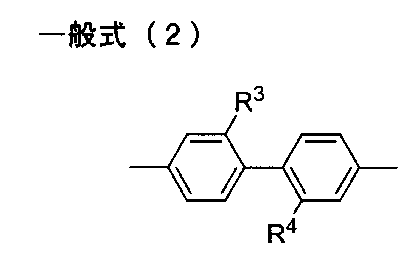
本開示の1実施形態は、前記本開示の1実施形態のポリイミドフィルムと、ラジカル重合性化合物及びカチオン重合性化合物の少なくとも1種の重合物を含有するハードコート層とを有する積層体を提供する。 One embodiment of the present disclosure provides a laminate having the polyimide film of one embodiment of the present disclosure and a hard coat layer containing a radically polymerizable compound and at least one polymer of a cationically polymerizable compound. .
本開示の1実施形態は、前記本開示の1実施形態のポリイミドフィルム、又は、前記本開示の1実施形態の積層体である、ディスプレイ用表面材を提供する。 An embodiment of the present disclosure provides a surface material for a display, which is the polyimide film of the embodiment of the present disclosure or the laminate of the embodiment of the present disclosure.
また、本開示の1実施形態は、前記本開示の1実施形態のポリイミドフィルム又は前記本開示の1実施形態の積層体と、
前記ポリイミドフィルム又は前記積層体の一方の面側に配置された、複数の導電部からなる透明電極と、
前記導電部の端部の少なくとも一方側において電気的に接続される複数の取り出し線と、を有するタッチパネル部材を提供する。
In addition, one embodiment of the present disclosure is the polyimide film of the one embodiment of the present disclosure or the laminate of the one embodiment of the present disclosure;
A transparent electrode composed of a plurality of conductive parts disposed on one side of the polyimide film or the laminate;
A touch panel member is provided having a plurality of lead lines electrically connected on at least one side of an end of the conductive portion.
また、本開示の1実施形態は、前記本開示の1実施形態のポリイミドフィルム又は前記本開示の1実施形態の積層体と、
前記ポリイミドフィルム又は前記積層体の一方の面側に配置された、対向基板間に液晶層を有してなる液晶表示部と、を有する液晶表示装置を提供する。
In addition, one embodiment of the present disclosure is the polyimide film of the one embodiment of the present disclosure or the laminate of the one embodiment of the present disclosure;
A liquid crystal display device comprising: a liquid crystal display unit having a liquid crystal layer between opposing substrates disposed on one side of the polyimide film or the laminate.
また、本開示の1実施形態は、前記本開示の1実施形態のポリイミドフィルム又は前記本開示の1実施形態の積層体と、
前記ポリイミドフィルム又は前記積層体の一方の面側に配置された、対向基板間に有機エレクトロルミネッセンス層を有してなる有機エレクトロルミネッセンス表示部と、を有する有機エレクトロルミネッセンス表示装置を提供する。
In addition, one embodiment of the present disclosure is the polyimide film of the one embodiment of the present disclosure or the laminate of the one embodiment of the present disclosure;
An organic electroluminescent display device comprising: an organic electroluminescent display unit having an organic electroluminescent layer between opposing substrates, disposed on one side of the polyimide film or the laminate.
本開示によれば、良好な透明性と耐久性を有し、光学的歪みが低減された樹脂フィルムを提供することができる。
また、本開示によれば、前記樹脂フィルムを有する積層体、及び、前記樹脂フィルム又は前記積層体であるディスプレイ用表面材、並びに、前記樹脂フィルム又は前記積層体を備えるタッチパネル部材、液晶表示装置、及び有機エレクトロルミネッセンス表示装置を提供することができる。
According to the present disclosure, a resin film having good transparency and durability and reduced optical distortion can be provided.
Further, according to the present disclosure, a laminate having the resin film, a surface material for a display which is the resin film or the laminate, a touch panel member including the resin film or the laminate, a liquid crystal display device, And an organic electroluminescent display can be provided.
I.ポリイミドフィルム
本開示の1実施態様のポリイミドフィルムは、動的粘弾性測定により得られる温度-損失正接(tanδ)曲線において、極大値が最大である第1ピークの高温側極小値の温度以上500℃以下の温度領域におけるtanδの最大値が0.18以上であり、
JIS K7361-1に準拠して測定する全光線透過率が、85%以上である。
I. Polyimide film The polyimide film of one embodiment of the present disclosure has a temperature-loss tangent (tan δ) curve obtained by dynamic viscoelasticity measurement. The maximum value of tan δ in the following temperature range is 0.18 or more,
The total light transmittance measured in accordance with JIS K7361-1 is 85% or more.
本開示によれば、動的粘弾性測定により得られる温度-損失正接(tanδ)曲線において、極大値が最大である第1ピークの高温側極小値の温度以上500℃以下の温度領域におけるtanδの最大値が0.18以上であり、JIS K7361-1に準拠して測定する全光線透過率が、85%以上であるポリイミドフィルムとしたことにより、良好な透明性と耐久性を有し、光学的歪みが低減された樹脂フィルムを提供することができる。 According to the present disclosure, in the temperature-loss tangent (tan δ) curve obtained by dynamic viscoelasticity measurement, tan δ in the temperature range of not less than 500 ° C. and not less than the temperature of the high temperature side minimum value of the first peak where the maximum value is maximum. A polyimide film having a maximum value of 0.18 or more and a total light transmittance of 85% or more measured according to JIS K7361-1, and thus has excellent transparency and durability, and optical Distortion can be provided.
本発明者らは、樹脂フィルムの中でも、その化学構造に由来し耐久性に優れることが知られているポリイミドフィルムに着目し検討を行った。当該検討の過程で、ポリイミドフィルムは光学的歪みが大きく、特に膜厚方向の位相差が大きいという問題を有することを知見した。
位相差は、屈折率の異方性が原因で発生する。高分子の場合、屈折率の異方性は、一般に固体中で高分子鎖がランダムに存在せず、方向性を持って規則正しく並んでいる場合に生じる。
ポリイミドは、他の樹脂と比較して、前記化学構造中に折れ曲がり可能な結合箇所が少ないため、高分子鎖中に直線状の分子構造が多くなりやすい。このような構造は、弾性率を高めることができる要因であるが、直線状の分子構造が膜厚方向に配向した状態で規則的に折り重なりやすくなる要因ともなるため、そのようなポリイミドフィルムでは膜厚方向の位相差が大きくなると想定される。
本発明者らは、ポリイミドフィルムの動的粘弾性測定により得られる温度-損失正接(tanδ)曲線(以下、単にtanδ曲線と称することがある。)において、第1ピークの高温側極小値の温度以上500℃以下の温度領域(以下、単に、第1ピーク高温側温度領域と称することがある。)におけるtanδの最大値が所定より大きいと、膜厚方向の位相差が小さくなる傾向を見出した。この理由は定かではないが、以下のように推測している。
tanδとは、損失弾性率を貯蔵弾性率によって除することによって得られる値であり、高分子材料の粘弾性特性を示す。図1に本開示のポリイミドフィルムのtanδ曲線、貯蔵弾性率曲線、及び損失弾性率曲線の一例を示す。図1において、tanδ曲線の極大値が最大である第1ピーク(1)の極大値の温度は、ポリイミドフィルムのガラス転移点を示している。そのため、第1ピーク(1)の極大値の温度以上の領域では、高分子鎖の多くは熱振動している状態である。
第1ピーク高温側温度領域において、tanδの値が大きいということは、粘性が高いことを表し、すなわちそれは高分子の分子間相互作用が小さいことを示していると考えられる。ここで、ポリイミドフィルム中に、直線状の分子構造が規則正しく並んで存在する場合には、分子間相互作用が相対的に大きくなって、第1ピーク高温側温度領域において高分子鎖の運動性が低下し、tanδの値が小さくなると考えられる。
ガラス転移温度以上の温度領域でtanδの値が小さいということは、分子間の相互作用が強く働くような位置関係に高分子鎖があることを表しており、その位置関係を取る場合に位相差が大きくなると考えられる。
一方、一般に位相差が小さいと言われる、高分子鎖が不規則に偏りなく存在しているポリイミドフィルムでは、分子間力が相対的に小さくなって、第1ピーク高温側温度領域において高分子鎖が振動しやすくなっていると考えられる。
このような理由から、tanδ曲線において、第1ピーク高温側温度領域におけるtanδの最大値が大きいポリイミドフィルムは、不規則に存在している高分子鎖の比率が高いため、低い位相差を示すと考えられる。
なお、後述の実施例4と比較例1で、同じ分子構造を有するポリイミド前駆体を用いてポリイミドフィルムを製造した場合であっても、製造方法が異なりポリイミドフィルム中の高分子鎖の状態が異なると、tanδ曲線において、第1ピーク高温側温度領域におけるtanδの最大値は大きく異なり、それに伴って位相差の大きさが大きく異なることが示されている。このことは、ポリイミドフィルムの位相差は、ポリイミドの組成のみに依存するわけではないこと、また、第1ピーク高温側温度領域におけるtanδの最大値は、位相差に関連したポリイミドフィルム中の高分子鎖の状態を表すことを示していると考えられる。
本発明者らは、上記知見に基づいて検討を進めた結果、第1ピーク高温側温度領域におけるtanδの最大値が0.18以上であるポリイミドフィルムでは、十分に低減された位相差が得られることを知見した。
The present inventors examined among the resin films paying attention to a polyimide film derived from its chemical structure and known to be excellent in durability. In the process of the said examination, it turned out that a polyimide film has a problem that optical distortion is large, and especially the phase contrast of a film thickness direction is large.
Retardation occurs due to the anisotropy of the refractive index. In the case of a polymer, the anisotropy of the refractive index generally occurs when the polymer chains in the solid are not randomly present but are oriented regularly.
Polyimides tend to have more linear molecular structures in polymer chains because there are fewer bendable bond sites in the chemical structure as compared to other resins. Such a structure is a factor that can increase the elastic modulus, but it also becomes a factor that makes it easy to fold regularly in a state where the linear molecular structure is oriented in the film thickness direction. It is assumed that the phase difference in the film thickness direction is large.
The present inventors measured the temperature-loss tangent (tan δ) curve (hereinafter may be simply referred to as the tan δ curve) obtained by measuring the dynamic viscoelasticity of a polyimide film, and the temperature of the high temperature side minimum value of the first peak. When the maximum value of tan δ in the temperature range of 500 ° C. or less (hereinafter, may be simply referred to as the first peak high temperature range) is larger than a predetermined value, the phase difference in the film thickness direction tends to decrease. . The reason for this is not clear, but is presumed as follows.
The tan δ is a value obtained by dividing the loss elastic modulus by the storage elastic modulus, and indicates the viscoelastic property of the polymer material. FIG. 1 shows an example of a tan δ curve, a storage elastic modulus curve, and a loss elastic modulus curve of the polyimide film of the present disclosure. In FIG. 1, the temperature of the maximum value of the first peak (1) at which the maximum value of the tan δ curve is the maximum indicates the glass transition point of the polyimide film. Therefore, in the region above the temperature of the maximum value of the first peak (1), most of the polymer chains are in a thermally oscillated state.
In the first peak high temperature region, a large value of tan δ indicates that the viscosity is high, that is, it is considered to indicate that the intermolecular interaction of the polymer is small. Here, when the linear molecular structures are regularly arranged in the polyimide film, the intermolecular interaction becomes relatively large, and the mobility of the polymer chain in the first peak high temperature region is increased. It is considered that the value decreases and the value of tan δ decreases.
The fact that the value of tan δ is small in the temperature range above the glass transition temperature indicates that the polymer chain is in a positional relationship in which the interaction between molecules works strongly, and the phase difference when the positional relationship is taken Is considered to be larger.
On the other hand, in the case of a polyimide film in which polymer chains are present irregularly and without bias, which is generally said to have a small retardation, the intermolecular force becomes relatively small, and the polymer chains in the first peak high temperature region Is considered to be easily vibrated.
For this reason, in the tan δ curve, a polyimide film having a large maximum value of tan δ in the first peak high temperature region exhibits a low phase difference because the proportion of randomly present polymer chains is high. Conceivable.
In addition, even if it is a case where a polyimide film is manufactured using the polyimide precursor which has the same molecular structure in the below-mentioned Example 4 and the comparative example 1, the manufacturing method differs and the state of the polymer chain in a polyimide film differs. And, in the tan δ curve, it is shown that the maximum value of tan δ in the first peak high temperature side temperature region is largely different, and the magnitude of the phase difference is significantly different accordingly. This means that the retardation of the polyimide film does not depend only on the composition of the polyimide, and the maximum value of tan δ in the first peak high temperature region is the polymer in the polyimide film related to the retardation. It is considered to indicate that it represents a chain state.
As a result of investigations based on the above findings, the present inventors can obtain a sufficiently reduced retardation with a polyimide film in which the maximum value of tan δ in the first peak high temperature region is 0.18 or more. I found that.
1.温度-損失正接(tanδ)曲線
本開示のポリイミドフィルムは、動的粘弾性測定により得られる温度-損失正接(tanδ)曲線において極大値が最大である第1ピークの高温側極小値の温度以上500℃以下の温度領域におけるtanδの最大値が0.18以上である。本開示のポリイミドフィルムは、tanδ)曲線において極大値が最大である第1ピークの高温側極小値の温度以上460℃以下の温度領域におけるtanδの最大値が0.18以上であっても良い。
本開示のポリイミドフィルムのtanδ曲線は、極大値が最大である第1ピークを有する。上述のように、第1のピークの極大値における温度はポリイミドフィルムのガラス転移温度を示す。本開示のポリイミドフィルムにおいて、第1ピークが存在する温度範囲に特に制限はないが、透明性の点から、400℃以下であることが好ましい。一方で、ポリイミドフィルムの耐熱性の点から、第1ピークが存在する温度範囲は、200℃以上であることが好ましく、更に250℃以上であることが好ましい。
図1に示されるように、本開示のポリイミドフィルムは、tanδ曲線において極大値が最大である第1ピーク(1)の高温側極小値(2)の温度(2t)以上500℃以下の温度領域におけるtanδの最大値(3)が0.18以上であることを特徴とする。上述のように、前記tanδの最大値がこのような大きい値をとるポリイミドフィルムでは、不規則に存在する折れ曲がった高分子鎖の割合が増加していると推定され、十分に低減された位相差を得ることが可能になる。更に低減された位相差を得る点から、前記tanδの最大値は0.20以上であることが好ましく、0.21以上であることがより好ましい。前記tanδの最大値の上限は、特に限定されるものではないが、0.50以下であることが好ましく、0.30以下であることがより好ましい。
なお、前記第1ピークの高温側極小値の温度以上500℃以下の温度領域におけるtanδの最大値には、第1ピークの極大値から高温側極小値の温度範囲、即ち、第1ピークの減少局面におけるtanδの値は含まれない。
前記第1ピークの高温側極小値の温度以上の温度領域は、第1ピークが存在する好ましい温度範囲との関係、即ち、ポリイミドフィルムの透明性及び耐熱性の点から、200℃以上450℃以下の温度領域であることが好ましく、250℃以上450℃以下の温度領域であることがより好ましく、300℃以上450℃以下の温度領域であることがより好ましく、350℃以上450℃以下の温度領域であることがより更に好ましい。
tanδ曲線において、前記第1ピークの高温側極小値の温度以上500℃以下の温度領域にピークが確認される場合には、当該ピークの極大値が0.18以上であってもよく、当該ピークの極大値は、0.20以上であることがより好ましく、0.21以上であることがより更に好ましい。
また、前記第1ピークの高温側極小値の温度以上500℃以下の温度領域に存在する当該ピークは、tanδ曲線において、極大値が2番目に大きい第2ピークであることが、位相差を低減する点から好ましい。
また、tanδ曲線において、極大値が最大である第1ピークを有し、当該第1ピークの極大値の温度より高い温度領域に、極大値が2番目に大きく、0.18以上である第2ピークを有することが、位相差を低減する点から好ましい。更に、tanδ曲線において、極大値が最大である第1ピークの高温側極小値の温度以上500℃以下の温度領域に、極大値が2番目に大きい第2ピークを有し、当該第2ピークの極大値が0.18以上であることが好ましく、0.20以上であることがより好ましく、0.21以上であることがより更に好ましい。
1. Temperature-loss tangent (tan δ) curve The polyimide film of the present disclosure has a temperature-loss tangent (tan δ) curve obtained by dynamic viscoelasticity measurement. The maximum value of tan δ in a temperature range of 0 ° C. or less is 0.18 or more. In the polyimide film of the present disclosure, the maximum value of tan δ may be 0.18 or more in the temperature range of not less than the temperature of the high temperature side minimum value of the first peak having the maximum value at the maximum in the tan δ curve and 460 ° C. or less.
The tan δ curve of the polyimide film of the present disclosure has a first peak whose maximum value is the largest. As mentioned above, the temperature at the maximum of the first peak indicates the glass transition temperature of the polyimide film. In the polyimide film of the present disclosure, the temperature range in which the first peak is present is not particularly limited, but is preferably 400 ° C. or less from the viewpoint of transparency. On the other hand, from the viewpoint of heat resistance of the polyimide film, the temperature range in which the first peak is present is preferably 200 ° C. or more, and more preferably 250 ° C. or more.
As shown in FIG. 1, the polyimide film of the present disclosure has a temperature range from a temperature (2 t) to 500 ° C. or less at the high temperature side minimum value (2) of the first peak (1) having the maximum value in the tan δ curve. Is characterized in that the maximum value (3) of tan δ in the above is 0.18 or more. As described above, in the polyimide film in which the maximum value of the tan δ takes such a large value, it is presumed that the proportion of irregularly present bent polymer chains is increased, and the retardation is sufficiently reduced. It is possible to get The maximum value of tan δ is preferably 0.20 or more, and more preferably 0.21 or more, in order to obtain a further reduced phase difference. The upper limit of the maximum value of tan δ is not particularly limited, but is preferably 0.50 or less, and more preferably 0.30 or less.
The maximum value of tan δ in the temperature range of not less than the temperature of the high temperature side minimum value of the first peak and not more than 500 ° C. is the temperature range of the high temperature side minimum value from the maximum value of the first peak, ie, the decrease of the first peak The value of tan δ in the phase is not included.
The temperature range above the temperature of the high temperature side minimum value of the first peak is 200 ° C. or more and 450 ° C. or less from the relationship with the preferable temperature range in which the first peak exists, ie, the transparency and heat resistance of the polyimide film. Is preferably 250 ° C. or more and 450 ° C. or less, more preferably 300 ° C. or more and 450 ° C. or less, and more preferably 350 ° C. or more and 450 ° C. or less It is even more preferable that
In the tan δ curve, in the case where a peak is confirmed in the temperature range of 500 ° C. or less of the temperature of the high temperature side minimum value of the first peak, the maximum value of the peak may be 0.18 or more; The maximum value of is more preferably 0.20 or more, and still more preferably 0.21 or more.
Moreover, the said peak which exists in the temperature range of 500 degreeC or less above the temperature of the high temperature side minimum value of the said 1st peak reduces a phase difference that a maximum value is the 2nd largest 2nd peak in a tan-delta curve. It is preferable from the point of
Further, the tan δ curve has a first peak having a maximum maximum value, and the second maximum value is 0.18 or more in a temperature range higher than the temperature of the maximum value of the first peak. Having a peak is preferable in terms of reducing the phase difference. Furthermore, the tan δ curve has a second peak with the second largest maximum value in the temperature range of 500 ° C. or less at a temperature higher than the temperature of the high temperature side minimum value of the first peak where the maximum value is the largest. The maximum value is preferably 0.18 or more, more preferably 0.20 or more, and still more preferably 0.21 or more.
tanδ曲線は、動的粘弾性測定によって、tanδ(tanδ=損失弾性率(E’’)/貯蔵弾性率(E’))から求められるものである。動的粘弾性測定は、23℃、56%RHの測定室で動的粘弾性測定装置 RSA-G2(TAインスツルメント製)によって、測定範囲を-40℃以上500℃以下として、変形様式として引張りを選定し、窒素雰囲気下、周波数1Hz、昇温速度10℃/min、最小荷重2g、Axial force>Dynamic Force 1.5%、Strain 0.1%により行うことができる。また、試験片は長さ40mm、幅5mmを用意し、チャック間距離を20mmとして測定することができる。ピーク及び変曲点の解析時は、目視評価せず、データを数値化して、数値から解析する。
なお、本開示において、tanδ曲線のピークとは、極大値である変曲点を有し、且つ、ピークの谷と谷の間であるピーク幅が3℃以上であるものをいい、ノイズ等測定由来の細かい上下変動については、前記ピークと解釈しない。
また、第1ピーク高温側温度領域において、測定対象であるポリイミドフィルムの試験片が溶融すると、tanδの値を正確に測定できなくなるため、数値に連続性が無くなり、極めて高いtanδの値を示すことがある。フィルムが溶融してtanδの数値が不連続になる場合とは、1℃ピッチで0.3以上大きさが変化した場合を目安とすることができる。しかし、このような値は、tanδ曲線の値とはいえないため、第1ピークの高温側極小値の温度以上500℃以下の温度領域におけるtanδの最大値とは解釈しない。即ち、第1ピークの高温側極小値の温度以上フィルムが溶融する温度未満の領域における値をtanδの最大値として解釈する。
The tan δ curve is obtained from tan δ (tan δ = loss modulus (E ′ ′) / storage modulus (E ′)) by dynamic viscoelasticity measurement. The dynamic viscoelasticity measurement is performed as a deformation mode with a measurement range of -40 ° C or more and 500 ° C or less by a dynamic viscoelasticity measurement device RSA-G2 (manufactured by TA Instruments) in a measurement room at 23 ° C and 56% RH. The tensile force can be selected, under a nitrogen atmosphere, at a frequency of 1 Hz, a heating rate of 10 ° C./min, a minimum load of 2 g, Axial force> Dynamic Force 1.5%, and Strain 0.1%. Moreover, a test piece prepares
In the present disclosure, the peak of the tan δ curve refers to a peak having an inflection point which is a maximum value and having a peak width of 3 ° C. or more between valleys of the peak and noise etc. The fine vertical fluctuation derived from is not interpreted as the above-mentioned peak.
In addition, when the test piece of the polyimide film to be measured melts in the first peak high temperature region, the value of tan δ can not be measured accurately, so the continuity of the numerical value is lost and the value of tan δ is extremely high. There is. In the case where the film melts and the value of tan δ becomes discontinuous, the case where the size changes by 0.3 or more at 1 ° C. pitch can be taken as a standard. However, such a value is not the value of the tan δ curve, so it is not interpreted as the maximum value of tan δ in the temperature range of 500 ° C. or less above the temperature of the high temperature side minimum value of the first peak. That is, the value in the range from the temperature of the high temperature side minimum value of the first peak to the temperature at which the film melts is interpreted as the maximum value of tan δ.
2.全光線透過率
本開示のポリイミドフィルムは、前記JIS K7361-1に準拠して測定する全光線透過率が、85%以上である。このように透過率が高いことから、透明性が良好になり、ガラス代替材料となり得る。本開示のポリイミドフィルムの前記JIS K7361-1に準拠して測定する全光線透過率は、更に88%以上であることが好ましく、より更に89%以上であることが好ましく、特に90%以上であることが好ましい。
本開示のポリイミドフィルムは、厚み5μm以上100μm以下において、前記JIS K7361-1に準拠して測定する全光線透過率が、85%以上であることが好ましく、更に88%以上であることが好ましく、より更に89%以上であることが好ましく、特に90%以上であることが好ましい。
また、本開示のポリイミドフィルムは、厚み50μm±5μmにおいて、前記JIS K7361-1に準拠して測定する全光線透過率が、85%以上であることが好ましく、更に88%以上であることが好ましく、より更に89%以上であることが好ましく、特に90%以上であることが好ましい。
JIS K7361-1に準拠して測定する全光線透過率は、例えば、ヘイズメーター(例えば村上色彩技術研究所製 HM150)により測定することができる。なお、ある厚みの全光線透過率の測定値から、異なる厚みの全光線透過率は、ランベルトベールの法則により換算値を求めることができ、それを利用することができる。
具体的には、ランベルトベールの法則によれば、透過率Tは、
Log10(1/T)=kcb
(k=物質固有の定数、c=濃度、b=光路長)で表される。
フィルムの透過率の場合、膜厚が変化しても密度が一定であると仮定するとcも定数となるので、上記式は、定数fを用いて
Log10(1/T)=fb
(f=kc)と表すことができる。ここで、ある膜厚の時の透過率がわかれば、各物質の固有の定数fを求めることができる。従って、T=1/10f・b の式を用いて、fに固有の定数、bに目標の膜厚を代入すれば、所望の膜厚の時の透過率を求めることができる。
2. Total Light Transmittance The polyimide film of the present disclosure has a total light transmittance of 85% or more as measured in accordance with the aforementioned JIS K7361-1. Such high transmittance allows for good transparency and can be a glass substitute material. The total light transmittance of the polyimide film of the present disclosure measured according to JIS K7361-1 is preferably 88% or more, more preferably 89% or more, and particularly preferably 90% or more. Is preferred.
The polyimide film of the present disclosure preferably has a total light transmittance of 85% or more, more preferably 88% or more, measured in accordance with JIS K7361-1 at a thickness of 5 μm to 100 μm. Further, it is more preferably 89% or more, and particularly preferably 90% or more.
The polyimide film of the present disclosure preferably has a total light transmittance of 85% or more, more preferably 88% or more, measured at a thickness of 50 μm ± 5 μm in accordance with JIS K7361-1. It is more preferably 89% or more, and particularly preferably 90% or more.
The total light transmittance measured according to JIS K7361-1 can be measured, for example, by a haze meter (for example, HM150 manufactured by Murakami Color Research Laboratory). From the measured value of the total light transmittance of a certain thickness, the converted total light transmittance of different thicknesses can be determined according to the Lambert-Beer's law, which can be used.
Specifically, according to Lambert-Beer's law, the transmittance T is
Log 10 (1 / T) = kcb
(K = material-specific constant, c = concentration, b = optical path length)
In the case of the transmittance of a film, c is also a constant assuming that the density is constant even if the film thickness changes, so the above equation can be calculated using Log 10 (1 / T) = fb
It can be expressed as (f = kc). Here, if the transmittance at a certain film thickness is known, the unique constant f of each substance can be determined. Therefore, the transmittance at the desired film thickness can be determined by substituting the specific constant for f and the target film thickness for b using the equation T = 1/10 fb .
3.ポリイミド
本開示において、ポリイミドは、テトラカルボン酸成分とジアミン成分とを反応させて得られるものである。テトラカルボン酸成分とジアミン成分の重合によって前駆体であるポリアミド酸を得た後、この前駆体をイミド化する。従って、本開示で用いられるポリイミドは、主鎖にテトラカルボン酸残基とジアミン残基とを含むものである。なお、テトラカルボン酸残基とは、テトラカルボン酸から、4つのカルボキシル基を除いた残基をいい、テトラカルボン酸二無水物から酸二無水物構造を除いた残基と同じ構造を表す。また、ジアミン残基とは、ジアミンから2つのアミノ基を除いた残基をいう。
3. Polyimide In the present disclosure, a polyimide is obtained by reacting a tetracarboxylic acid component and a diamine component. After the polyamic acid which is a precursor is obtained by polymerizing a tetracarboxylic acid component and a diamine component, the precursor is imidized. Accordingly, the polyimide used in the present disclosure is one containing a tetracarboxylic acid residue and a diamine residue in the main chain. The term "tetracarboxylic acid residue" refers to a residue obtained by removing four carboxyl groups from tetracarboxylic acid, and represents the same structure as a residue obtained by removing an acid dianhydride structure from tetracarboxylic acid dianhydride. Moreover, a diamine residue means the residue remove | excluding two amino groups from diamine.
本開示で特定される前記粘弾性特性と透明性が得られる限り、ポリイミドフィルムの製造は、ポリイミド前駆体の状態で成形しそのあと、熱処理によってポリイミドとする熱イミド化法で行っても、既にポリイミドとなっている(たとえば化学イミド化によってポリイミドとされた)溶液から溶媒を除去することで行ってもよく、また、それら熱イミド化と化学イミド化とを併用した方法で行うこともできる。しかし、中でも、位相差を低減しやすい点から、本開示のポリイミドフィルムは、ポリイミド前駆体溶液を用いて製膜後に加熱(熱イミド化)によりポリイミドフィルムとする方法で製造することが好ましい。
一般に、ポリイミドよりもポリイミド前駆体の方が骨格の柔軟性が高く、フィルム中に不規則な形で存在しやすい。そういった不規則な状態で存在しているポリイミド前駆体から、実質的な固層中でイミド化をすることで、ポリイミドとした後でも、不規則な構造を取りやすい。その結果、ポリイミド前駆体の製膜後に加熱によりポリイミドフィルムとする製造方法の方が、位相差が低くなりやすいと推定される。
化学イミド化により溶液中でポリイミド前駆体(ポリアミド酸)をイミド化して得られたポリイミドは、製膜時に、分子構造の折れ曲がり可能な可動部が減少しているためにより直線状の分子構造になりやすい。得られるポリイミドフィルム中のポリイミドが、膜厚に平行方向に配向した状態で規則的に折り重なりやすくなることから、分子間相互作用が大きくなるとともに、位相差が大きくなりやすい。ただし、ポリイミド溶液からの製膜でも、ポリイミドが柔軟な骨格を有していたり、瞬間的に溶媒を除去するなど手法で、不規則な状態を作り出すことができる場合もある。
このような理由から、tanδ曲線において、第1ピーク高温側温度領域におけるtanδの最大値を0.18以上の範囲にするためには、熱イミド化を用いることが好ましい。
As long as the visco-elastic properties and transparency specified in the present disclosure can be obtained, the production of the polyimide film may be carried out by a thermal imidization method in which it is molded in the state of a polyimide precursor and then heat treated to form polyimide. It may be carried out by removing the solvent from the solution which has become polyimide (for example, made into polyimide by chemical imidization), or it can also be carried out by a method using the thermal imidization and the chemical imidization in combination. However, among them, it is preferable to manufacture the polyimide film of the present disclosure by a method of forming a polyimide film by heating (thermal imidization) after film formation using a polyimide precursor solution, from the viewpoint of easily reducing retardation.
In general, polyimide precursors have higher backbone flexibility than polyimides and are more likely to be present irregularly in the film. By imidation in such a solid phase from the polyimide precursor which exists in such an irregular state, even after being made into a polyimide, it is easy to take an irregular structure. As a result, it is presumed that the phase difference tends to be lower in the method of producing a polyimide film by heating after film formation of the polyimide precursor.
The polyimide obtained by imidizing a polyimide precursor (polyamic acid) in a solution by chemical imidization has a linear molecular structure due to the reduction of bendable movable parts of the molecular structure during film formation. Cheap. Since the polyimide in the obtained polyimide film is easily folded regularly in a state in which it is oriented in a direction parallel to the film thickness, the intermolecular interaction becomes large and the retardation easily becomes large. However, even in the case of film formation from a polyimide solution, it may be possible to create an irregular state by a method such as polyimide having a flexible skeleton or instantaneously removing the solvent.
From such reasons, it is preferable to use thermal imidization in order to make the maximum value of tan δ in the first peak high temperature region within the range of 0.18 or more in the tan δ curve.
本開示で用いられるポリイミドにおいて、テトラカルボン酸残基になる、テトラカルボン酸成分としては、例えば、芳香族環を有するテトラカルボン酸成分が、ポリイミドフィルムの表面硬度を向上する点から好ましい。
芳香族環を有するテトラカルボン酸成分としては、芳香族環を有するテトラカルボン酸二無水物、例えば、ピロメリット酸二無水物、3,3’,4,4’-ベンゾフェノンテトラカルボン酸二無水物、2,2’,3,3’-ベンゾフェノンテトラカルボン酸二無水物、3,3’,4,4’-ビフェニルテトラカルボン酸二無水物、2,2’,3,3’-ビフェニルテトラカルボン酸二無水物、2,2-ビス(3,4-ジカルボキシフェニル)プロパン二無水物、2,2-ビス(2,3-ジカルボキシフェニル)プロパン二無水物、ビス(3,4-ジカルボキシフェニル)エーテル二無水物、ビス(3,4-ジカルボキシフェニル)スルホン二無水物、1,1-ビス(2,3-ジカルボキシフェニル)エタン二無水物、ビス(2,3-ジカルボキシフェニル)メタン二無水物、ビス(3,4-ジカルボキシフェニル)メタン二無水物、2,2-ビス(3,4-ジカルボキシフェニル)-1,1,1,3,3,3-ヘキサフルオロプロパン二無水物、2,2-ビス(2,3-ジカルボキシフェニル)-1,1,1,3,3,3-ヘキサフルオロプロパン二無水物、1,3-ビス〔(3,4-ジカルボキシ)ベンゾイル〕ベンゼン二無水物、1,4-ビス〔(3,4-ジカルボキシ)ベンゾイル〕ベンゼン二無水物、2,2-ビス{4-〔4-(1,2-ジカルボキシ)フェノキシ〕フェニル}プロパン二無水物、2,2-ビス{4-〔3-(1,2-ジカルボキシ)フェノキシ〕フェニル}プロパン二無水物、ビス{4-〔4-(1,2-ジカルボキシ)フェノキシ〕フェニル}ケトン二無水物、ビス{4-〔3-(1,2-ジカルボキシ)フェノキシ〕フェニル}ケトン二無水物、4,4’-ビス〔4-(1,2-ジカルボキシ)フェノキシ〕ビフェニル二無水物、4,4’-ビス〔3-(1,2-ジカルボキシ)フェノキシ〕ビフェニル二無水物、ビス{4-〔4-(1,2-ジカルボキシ)フェノキシ〕フェニル}ケトン二無水物、ビス{4-〔3-(1,2-ジカルボキシ)フェノキシ〕フェニル}ケトン二無水物、ビス{4-〔4-(1,2-ジカルボキシ)フェノキシ〕フェニル}スルホン二無水物、ビス{4-〔3-(1,2-ジカルボキシ)フェノキシ〕フェニル}スルホン二無水物、ビス{4-〔4-(1,2-ジカルボキシ)フェノキシ〕フェニル}スルフィド二無水物、ビス{4-〔3-(1,2-ジカルボキシ)フェノキシ〕フェニル}スルフィド二無水物、4,4’-(ヘキサフルオロイソプロピリデン)ジフタル酸無水物、3,4’-(ヘキサフルオロイソプロピリデン)ジフタル酸無水物、3,3’-(ヘキサフルオロイソプロピリデン)ジフタル酸無水物、4,4’-オキシジフタル酸無水物、3,4’-オキシジフタル酸無水物、2,3,6,7-ナフタレンテトラカルボン酸二無水物、1,4,5,8-ナフタレンテトラカルボン酸二無水物、1,2,5,6-ナフタレンテトラカルボン酸二無水物、1,2,3,4-ベンゼンテトラカルボン酸二無水物、3,4,9,10-ぺリレンテトラカルボン酸二無水物、2,3,6,7-アントラセンテトラカルボン酸二無水物、1,2,7,8-フェナントレンテトラカルボン酸二無水物等が挙げられる。
In the polyimide used in the present disclosure, as the tetracarboxylic acid component to be a tetracarboxylic acid residue, for example, a tetracarboxylic acid component having an aromatic ring is preferable in terms of improving the surface hardness of the polyimide film.
As the tetracarboxylic acid component having an aromatic ring, tetracarboxylic acid dianhydride having an aromatic ring, for example, pyromellitic acid dianhydride, 3,3 ′, 4,4′-benzophenonetetracarboxylic acid dianhydride 2,2 ', 3,3'-benzophenonetetracarboxylic dianhydride, 3,3', 4,4'-biphenyltetracarboxylic dianhydride, 2,2 ', 3,3'-biphenyltetracarboxylic acid Acid dianhydride, 2,2-bis (3,4-dicarboxyphenyl) propane dianhydride, 2,2-bis (2,3-dicarboxyphenyl) propane dianhydride, bis (3,4-di Carboxyphenyl) ether dianhydride, bis (3,4-dicarboxyphenyl) sulfone dianhydride, 1,1-bis (2,3-dicarboxyphenyl) ethane dianhydride, bis (2,3-dicarboxy) Fen ) Methane dianhydride, bis (3,4-dicarboxyphenyl) methane dianhydride, 2,2-bis (3,4-dicarboxyphenyl) -1,1,1,3,3,3-hexafluoro Propane dianhydride, 2,2-bis (2,3-dicarboxyphenyl) -1,1,1,3,3,3-hexafluoropropane dianhydride, 1,3-bis [(3,4- Dicarboxy) benzoyl] benzene dianhydride, 1,4-bis [(3,4-dicarboxy) benzoyl] benzene dianhydride, 2,2-bis {4- [4- (1,2-dicarboxy)] Phenoxy] phenyl} propane dianhydride, 2,2-bis {4- [3- (1,2-dicarboxy) phenoxy] phenyl} propane dianhydride, bis {4- [4- (1,2-di] Carboxy) phenoxy] phenyl} ketone dianhydride, bi {4- [3- (1,2-dicarboxy) phenoxy] phenyl} ketone dianhydride, 4,4'-bis [4- (1,2-dicarboxy) phenoxy] biphenyl dianhydride, 4, 4'-bis [3- (1,2-dicarboxy) phenoxy] biphenyl dianhydride, bis {4- [4- (1,2-dicarboxy) phenoxy] phenyl} ketone dianhydride, bis {4- [3- (1,2-dicarboxy) phenoxy] phenyl} ketone dianhydride, bis {4- [4- (1,2-dicarboxy) phenoxy] phenyl} sulfone dianhydride, bis {4- [3 -(1,2-dicarboxy) phenoxy] phenyl} sulfone dianhydride, bis {4- [4- (1,2-dicarboxy) phenoxy] phenyl} sulfide dianhydride, bis {4- [3- ( 1,2-dicarboxy) Noxy] phenyl} sulfide dianhydride, 4,4 '-(hexafluoroisopropylidene) diphthalic anhydride, 3,4'-(hexafluoroisopropylidene) diphthalic anhydride, 3,3 '-(hexafluoroisopropyl) (Redidene) diphthalic anhydride, 4,4'-oxydiphthalic anhydride, 3,4'-oxydiphthalic anhydride, 2,3,6,7-naphthalenetetracarboxylic acid dianhydride, 1,4,5,8 -Naphthalenetetracarboxylic acid dianhydride, 1,2,5,6-naphthalenetetracarboxylic acid dianhydride, 1,2,3,4-benzenetetracarboxylic acid dianhydride, 3,4,9,10-methane Rylene tetracarboxylic acid dianhydride, 2,3,6,7-anthracene tetracarboxylic acid dianhydride, 1,2,7,8-phenanthrene tetracarboxylic acid dianhydride etc. are mentioned.
また、本開示に用いるテトラカルボン酸成分としては、ポリイミドフィルムの光透過性の点から、脂肪族環を有するテトラカルボン酸成分も好ましい。
脂肪族環を有するテトラカルボン酸二無水物としては、例えば、シクロヘキサンテトラカルボン酸二無水物、シクロペンタンテトラカルボン酸二無水物、ジシクロヘキサン-3,4,3’,4’-テトラカルボン酸二無水物、シクロブタンテトラカルボン酸二無水物等が挙げられる。
なお、上述したテトラカルボン酸成分は、単独でも、2種以上を混合して用いることもできる。
Moreover, as a tetracarboxylic acid component used for this indication, the tetracarboxylic acid component which has an aliphatic ring is also preferable from the point of the light transmittance of a polyimide film.
Examples of tetracarboxylic acid dianhydrides having an aliphatic ring include cyclohexanetetracarboxylic acid dianhydride, cyclopentanetetracarboxylic acid dianhydride, dicyclohexane-3,4,3 ′, 4′-tetracarboxylic acid Anhydride, cyclobutane tetracarboxylic acid dianhydride, etc. are mentioned.
In addition, the tetracarboxylic acid component mentioned above can also be used individually or in mixture of 2 or more types.
ジアミン成分としては、例えば、芳香族環を有するジアミンが、ポリイミドフィルムの耐久性と、表面硬度の点から好ましい。
また、本開示に用いるジアミン成分としては、ポリイミドフィルムの光透過性の点から、脂肪族環を有するジアミンも好ましい。
また、本開示に係るポリイミドフィルムは、中でも、主鎖にケイ素原子を有するジアミン残基を含むポリイミドを含有することが好ましい。主鎖にケイ素原子を有するジアミン残基を含むポリイミドでは、ケイ素原子部分が折れ曲がり構造となり得るため、より多くの折れ曲がった分子構造を含む高分子鎖を有するポリイミドを得やすく、本開示のポリイミドフィルムを得やすい点から好ましい。
As a diamine component, the diamine which has an aromatic ring, for example is preferable from the point of durability of a polyimide film, and surface hardness.
Moreover, as a diamine component used for this indication, the diamine which has an aliphatic ring is also preferable from the point of the light transmittance of a polyimide film.
Moreover, it is preferable that the polyimide film which concerns on this indication contains the polyimide which contains the diamine residue which has a silicon atom in a principal chain especially. In the case of a polyimide containing a diamine residue having a silicon atom in the main chain, the silicon atom portion can be in a bent structure, so it is easy to obtain a polyimide having a polymer chain containing a more bent molecular structure. It is preferable from the point which is easy to obtain.
芳香族環を有するジアミンとしては、例えば、4,4’-ジアミノジフェニルスルホン、3,4’-ジアミノジフェニルスルホン、2,2-ビス(4-アミノフェニル)プロパン、2,2-ビス(4-アミノフェニル)ヘキサフルオロプロパン、p-フェニレンジアミン、o-フェニレンジアミン、3,4’-ジアミノジフェニルエーテル、4,4’-ジアミノジフェニルエーテル、3,4’-ジアミノジフェニルスルフィド、4,4’-ジアミノジフェニルスルフィド、4,4’-ジアミノベンゾフェノン、3,4’-ジアミノベンゾフェノン、4,4’-ジアミノベンズアニリド、4,4’-ジアミノジフェニルメタン、3,4’-ジアミノジフェニルメタン、2-(3-アミノフェニル)-2-(4-アミノフェニル)プロパン、2-(3-アミノフェニル)-2-(4-アミノフェニル)-1,1,1,3,3,3-ヘキサフルオロプロパン、1,1-ジ(4-アミノフェニル)-1-フェニルエタン、1-(3-アミノフェニル)-1-(4-アミノフェニル)-1-フェニルエタン、1,3-ビス(4-アミノフェノキシ)ベンゼン、1,4-ビス(4-アミノフェノキシ)ベンゼン、1,3-ビス(4-アミノベンゾイル)ベンゼン、1,4-ビス(4-アミノベンゾイル)ベンゼン、1,3-ビス(4-アミノ-α,α-ジメチルベンジル)ベンゼン、1,4-ビス(4-アミノ-α,α-ジメチルベンジル)ベンゼン、1,3-ビス(4-アミノ-α,α-ジトリフルオロメチルベンジル)ベンゼン、1,4-ビス(4-アミノ-α,α-ジトリフルオロメチルベンジル)ベンゼン、N,N’-ビス(4-アミノフェニル)テレフタルアミド、9,9-ビス(4-アミノフェニル)フルオレン、3,3’-ジクロロ-4,4’-ジアミノビフェニル、3,3’-ジメトキシ-4,4’-ジアミノビフェニル、3,3’-ジメチル-4,4’-ジアミノビフェニル、4,4’-ビス(4-アミノフェノキシ)ビフェニル、ビス[4-(4-アミノフェノキシ)フェニル]ケトン、ビス[4-(4-アミノフェノキシ)フェニル]スルホン、ビス[4-(4-アミノフェノキシ)フェニル]エーテル、2,2-ビス[4-(4-アミノフェノキシ)フェニル]プロパン、2,2-ビス[4-(4-アミノフェノキシ)フェニル]-1,1,1,3,3,3-ヘキサフルオロプロパン、1,3-ビス[4-(4-アミノフェノキシ)ベンゾイル]ベンゼン、1,4-ビス[4-(4-アミノフェノキシ)ベンゾイル]ベンゼン、1,3-ビス[4-(4-アミノフェノキシ)-α,α-ジメチルベンジル]ベンゼン、1,4-ビス[4-(4-アミノフェノキシ)-α,α-ジメチルベンジル]ベンゼン、4,4’-ビス[4-(4-アミノフェノキシ)ベンゾイル]ジフェニルエーテル、4,4’-ビス[4-(4-アミノ-α,α-ジメチルベンジル)フェノキシ]ベンゾフェノン、4,4’-ビス[4-(4-アミノ-α,α-ジメチルベンジル)フェノキシ]ジフェニルスルホン、4,4’-ビス[4-(4-アミノフェノキシ)フェノキシ]ジフェニルスルホン、3,3’-ジアミノ-4,4’-ジフェノキシベンゾフェノン、3,3’-ジアミノ-4,4’-ジビフェノキシベンゾフェノン、3,3’-ジアミノ-4-フェノキシベンゾフェノン、3,3’-ジアミノ-4-ビフェノキシベンゾフェノン、6,6’-ビス(4-アミノフェノキシ)-3,3,3’,3’-テトラメチル-1,1’-スピロビインダン等、及び、前記ジアミンの芳香族環上水素原子の一部若しくは全てをフルオロ基、メチル基、メトキシ基、トリフルオロメチル基、又はトリフルオロメトキシ基から選ばれた置換基で置換したジアミンを使用することができる。 As the diamine having an aromatic ring, for example, 4,4′-diaminodiphenyl sulfone, 3,4′-diaminodiphenyl sulfone, 2,2-bis (4-aminophenyl) propane, 2,2-bis (4-bis (4-aminophenyl) propane) Aminophenyl) hexafluoropropane, p-phenylenediamine, o-phenylenediamine, 3,4'-diaminodiphenyl ether, 4,4'-diaminodiphenyl ether, 3,4'-diaminodiphenyl sulfide, 4,4'-diaminodiphenyl sulfide 4,4'-Diaminobenzophenone, 3,4'-diaminobenzophenone, 4,4'-diaminobenzanilide, 4,4'-diaminodiphenylmethane, 3,4'-diaminodiphenylmethane, 2- (3-aminophenyl) -2- (4-aminophenyl) propane, 2 (3-aminophenyl) -2- (4-aminophenyl) -1,1,1,3,3,3-hexafluoropropane, 1,1-di (4-aminophenyl) -1-phenylethane, 1 -(3-aminophenyl) -1- (4-aminophenyl) -1-phenylethane, 1,3-bis (4-aminophenoxy) benzene, 1,4-bis (4-aminophenoxy) benzene, 1, 3-Bis (4-aminobenzoyl) benzene, 1,4-bis (4-aminobenzoyl) benzene, 1,3-bis (4-amino-α, α-dimethylbenzyl) benzene, 1,4-bis (4 -Amino-α, α-dimethylbenzyl) benzene, 1,3-bis (4-amino-α, α-ditrifluoromethylbenzyl) benzene, 1,4-bis (4-amino-α, α-ditrifluoromethyl) Ben B) benzene, N, N'-bis (4-aminophenyl) terephthalamide, 9,9-bis (4-aminophenyl) fluorene, 3,3'-dichloro-4,4'-diaminobiphenyl, 3,3 '-Dimethoxy-4,4'-diaminobiphenyl, 3,3'-dimethyl-4,4'-diaminobiphenyl, 4,4'-bis (4-aminophenoxy) biphenyl, bis [4- (4-aminophenoxy] ) Phenyl] ketone, bis [4- (4-aminophenoxy) phenyl] sulfone, bis [4- (4-aminophenoxy) phenyl] ether, 2,2-bis [4- (4-aminophenoxy) phenyl] propane 2,2-bis [4- (4-aminophenoxy) phenyl] -1,1,1,3,3,3-hexafluoropropane, 1,3-bis [4- (4- (4-amino) Minophenoxy) benzoyl] benzene, 1,4-bis [4- (4-aminophenoxy) benzoyl] benzene, 1,3-bis [4- (4-aminophenoxy) -α, α-dimethylbenzyl] benzene, 1 , 4-Bis [4- (4-aminophenoxy) -α, α-dimethylbenzyl] benzene, 4,4'-bis [4- (4-aminophenoxy) benzoyl] diphenyl ether, 4,4'-bis [4 -(4-amino-α, α-dimethylbenzyl) phenoxy] benzophenone, 4,4'-bis [4- (4-amino-α, α-dimethylbenzyl) phenoxy] diphenyl sulfone, 4,4'-bis [4 4- (4-Aminophenoxy) phenoxy] diphenyl sulfone, 3,3'-diamino-4,4'-diphenoxybenzophenone, 3,3'-diamino 4,4'-Dibiphenoxybenzophenone, 3,3'-diamino-4-phenoxybenzophenone, 3,3'-diamino-4-biphenoxybenzophenone, 6,6'-bis (4-aminophenoxy) -3,3 And 3 ', 3'-tetramethyl-1,1'-spirobiindane and the like, and part or all of hydrogen atoms on the aromatic ring of the diamine described above as fluoro, methyl, methoxy, trifluoromethyl or Diamines substituted with substituents selected from trifluoromethoxy groups can be used.
脂肪族環を有するジアミンとしては、例えば、trans-シクロヘキサンジアミン、trans-1,4-ビスメチレンシクロヘキサンジアミン、2,6-ビス(アミノメチル)ビシクロ[2,2,1]ヘプタン、2,5-ビス(アミノメチル)ビシクロ[2,2,1]ヘプタン等が挙げられる。 Examples of the diamine having an aliphatic ring include trans-cyclohexanediamine, trans-1,4-bismethylenecyclohexanediamine, 2,6-bis (aminomethyl) bicyclo [2,2,1] heptane, 2,5- Bis (aminomethyl) bicyclo [2,2,1] heptane and the like can be mentioned.
主鎖にケイ素原子を有するジアミンとしては、例えば、下記一般式(A)で表されるジアミンが挙げられる。 As a diamine which has a silicon atom in a principal chain, the diamine represented by the following general formula (A) is mentioned, for example.
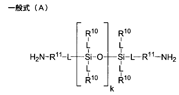
R10で表される1価の炭化水素基としては、炭素数1以上20以下のアルキル基、アリール基、及びこれらの組み合わせが挙げられる。アルキル基は、直鎖状、分岐状、環状のいずれであってもよく、直鎖状又は分岐状と環状の組合せであっても良い。
炭素数1以上20以下のアルキル基としては、炭素数1以上10以下のアルキル基であることが好ましく、具体的には、メチル基、エチル基、プロピル基、イソプロピル基、ブチル基、イソブチル基、t-ブチル基、ペンチル基、ヘキシル基等が挙げられる。前記環状のアルキル基としては、炭素数3以上10以下のシクロアルキル基であることが好ましく、具体的には、シクロペンチル基、シクロヘキシル基等が挙げられる。前記アリール基としては、炭素数6以上12以下のアリール基であることが好ましく、具体的には、フェニル基、トリル基、ナフチル基等が挙げられる。また、R10で表される1価の炭化水素基としては、アラルキル基であっても良く、例えば、ベンジル基、フェニルエチル基、フェニルプロピル基等が挙げられる。
酸素原子又は窒素原子を含んでいても良い炭化水素基としては、例えば後述する2価の炭化水素基と前記1価の炭化水素基とをエーテル結合、カルボニル結合、エステル結合、アミド結合、及びイミノ結合(-NH-)の少なくとも1つで結合した基が挙げられる。
R10で表される1価の炭化水素基が有していても良い置換基としては、本開示の効果が損なわれない範囲で特に限定されず、例えば、フッ素原子、塩素原子等のハロゲン原子、水酸基等が挙げられる。
The monovalent hydrocarbon groups represented by R 10, the
The alkyl group having 1 to 20 carbon atoms is preferably an alkyl group having 1 to 10 carbon atoms, and specifically, a methyl group, an ethyl group, a propyl group, an isopropyl group, a butyl group, an isobutyl group, Examples thereof include t-butyl group, pentyl group and hexyl group. The cyclic alkyl group is preferably a cycloalkyl group having 3 to 10 carbon atoms, and specific examples thereof include a cyclopentyl group and a cyclohexyl group. The aryl group is preferably an aryl group having 6 to 12 carbon atoms, and specific examples thereof include a phenyl group, a tolyl group and a naphthyl group. The monovalent hydrocarbon group represented by R 10 may be an aralkyl group, and examples thereof include a benzyl group, a phenylethyl group and a phenylpropyl group.
Examples of the hydrocarbon group which may contain an oxygen atom or a nitrogen atom include, for example, an ether bond, a carbonyl bond, an ester bond, an amide bond, and an imino bond between a divalent hydrocarbon group described later and the monovalent hydrocarbon group. Included is a group bonded via at least one of the bonds (—NH—).
The substituent which the monovalent hydrocarbon group represented by R 10 may have is not particularly limited as long as the effects of the present disclosure are not impaired, and for example, a halogen atom such as a fluorine atom or a chlorine atom And hydroxyl groups.
R10で表される1価の炭化水素基としては、屈曲耐性の向上と表面硬度の両立性の点から、炭素数1以上3以下のアルキル基、又は炭素数6以上10以下のアリール基であることが好ましい。炭素数1以上3以下のアルキル基としては、メチル基であることがより好ましく、前記炭素数6以上10以下のアリール基としては、フェニル基であることがより好ましい。 The monovalent hydrocarbon group represented by R 10 is an alkyl group having 1 to 3 carbon atoms or an aryl group having 6 to 10 carbon atoms from the viewpoint of improving bending resistance and compatibility with surface hardness. Is preferred. The alkyl group having 1 to 3 carbon atoms is more preferably a methyl group, and the aryl group having 6 to 10 carbon atoms is more preferably a phenyl group.
R11で表される2価の炭化水素基としては、炭素数1以上20以下のアルキレン基、アリーレン基、及びこれらの組み合わせの基が挙げられる。アルキレン基は、直鎖状、分岐状、環状のいずれであってもよく、直鎖状又は分岐状と環状の組合せであっても良い。
炭素数1以上20以下のアルキレン基としては、炭素数1以上10以下のアルキレン基であることが好ましく、例えば、メチレン基、エチレン基、各種プロピレン基、各種ブチレン基、シクロヘキシレン基等の直鎖状又は分岐状アルキレン基と環状アルキレン基との組合せの基などを挙げることができる。
前記アリーレン基としては、炭素数6~12のアリーレン基であることが好ましく、アリーレン基としては、フェニレン基、ビフェニレン基、ナフチレン基等が挙げられ、更に後述する芳香族環に対する置換基を有していても良い。
酸素原子又は窒素原子を含んでいても良い2価の炭化水素基としては、前記2価の炭化水素基同士をエーテル結合、カルボニル結合、エステル結合、アミド結合、及びイミノ結合(-NH-)の少なくとも1つで結合した基が挙げられる。
R11で表される2価の炭化水素基が有していても良い置換基としては、前記R10で表される1価の炭化水素基が有していても良い置換基と同様であって良い。
Examples of the divalent hydrocarbon group represented by R 11, an alkylene group having 1 to 20 carbon atoms, an arylene group, and a group of combinations thereof. The alkylene group may be linear, branched or cyclic, and may be linear or a combination of branched and cyclic.
The alkylene group having 1 or more and 20 or less carbon atoms is preferably an alkylene group having 1 or more and 10 or less carbon atoms, and for example, a straight chain such as methylene group, ethylene group, various propylene groups, various butylene groups and cyclohexylene groups Examples include groups in combination of linear or branched alkylene groups and cyclic alkylene groups.
The arylene group is preferably an arylene group having a carbon number of 6 to 12, and examples of the arylene group include a phenylene group, a biphenylene group, and a naphthylene group, and further have a substituent for the aromatic ring described later. May be
Examples of the divalent hydrocarbon group which may contain an oxygen atom or a nitrogen atom include an ether bond, a carbonyl bond, an ester bond, an amide bond, and an imino bond (-NH-) between the above-mentioned divalent hydrocarbon groups. At least one bonded group is mentioned.
The substituent which the divalent hydrocarbon group represented by R 11 may have is the same as the substituent which the monovalent hydrocarbon group represented by R 10 may have. It is good.
R11で表される2価の炭化水素基としては、屈曲耐性の向上と表面硬度の両立性の点から、炭素数1以上6以下のアルキレン基、又は炭素数6以上10以下のアリーレン基であることが好ましく、更に、炭素数2以上4以下のアルキレン基であることがより好ましい。 The divalent hydrocarbon group represented by R 11 is an alkylene group having 1 to 6 carbon atoms, or an arylene group having 6 to 10 carbon atoms, from the viewpoint of improving bending resistance and compatibility with surface hardness. It is more preferable that it is an alkylene group having 2 to 4 carbon atoms.
中でも、低位相差を実現し、且つ、屈曲耐性及び表面硬度の両立性を向上する観点から、主鎖にケイ素原子を有するジアミン残基は、主鎖にケイ素原子を1個又は2個有するジアミン残基であることが好ましい。
ジアミン残基が主鎖に有するケイ素原子の個数に特に制限はないが、1個又は2個であることが好ましく、2個であるとより好ましい。珪素原子が3個以上になると、低位相差を実現するための効果が飽和するうえに、ポリイミドの柔軟性が高くなりすぎて耐熱性に影響がでる可能性があるためである。
Among them, a diamine residue having a silicon atom in the main chain is a diamine residue having one or two silicon atoms in the main chain, from the viewpoint of achieving low retardation and improving the compatibility of bending resistance and surface hardness. It is preferably a group.
The number of silicon atoms in the main chain of the diamine residue is not particularly limited, but is preferably one or two, and more preferably two. When the number of silicon atoms is 3 or more, the effect for realizing low retardation is saturated, and the flexibility of the polyimide is too high, which may affect the heat resistance.
主鎖にケイ素原子を1個有するジアミンとしては、例えば、下記一般式(A-1)で表されるジアミンが挙げられる。また、主鎖にケイ素原子を2個有するジアミンとしては、例えば、下記一般式(A-2)で表されるジアミンが挙げられる。 Examples of diamines having one silicon atom in the main chain include diamines represented by the following general formula (A-1). Further, examples of the diamine having two silicon atoms in the main chain include diamines represented by the following general formula (A-2).
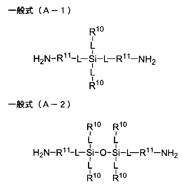
低位相差と耐熱性の両立の点から、主鎖にケイ素原子を有するジアミン残基の分子量は、1000以下であることが好ましく、800以下であることがより好ましく、500以下であることがより更に好ましく、300以下であることが特に好ましい。
ジアミン残基の分子量は、ジアミンの分子量からアミノ基(-NH2)2個の分子量(32)を減じて算出される。
主鎖にケイ素原子を有するジアミン残基は単独でも、2種以上を混合して用いることもできる。
From the viewpoint of achieving both low retardation and heat resistance, the molecular weight of the diamine residue having a silicon atom in the main chain is preferably 1,000 or less, more preferably 800 or less, and still more preferably 500 or less. Preferably, it is 300 or less.
The molecular weight of the diamine residue is calculated by subtracting the molecular weight (32) of two amino groups (-NH 2 ) from the molecular weight of the diamine.
The diamine residue which has a silicon atom in a principal chain can also be used individually or in mixture of 2 or more types.
また、主鎖にケイ素原子を1個又は2個有するジアミンが、ケイ素原子を2個有するジアミンであることが、得られるポリイミドの光透過性の点、及び屈曲耐性及び表面硬度の点から好ましく、更に、1,3-ビス(3-アミノプロピル)テトラメチルジシロキサン、1,3-ビス(4-アミノブチル)テトラメチルジシロキサン、1,3-ビス(5-アミノペンチル)テトラメチルジシロキサン等が、これら化合物の入手容易性や得られるポリイミドの光透過性と表面硬度の両立の観点から好ましい。 In addition, it is preferable that the diamine having one or two silicon atoms in the main chain is a diamine having two silicon atoms from the viewpoint of light transmittance of the resulting polyimide, and in terms of bending resistance and surface hardness, Furthermore, 1,3-bis (3-aminopropyl) tetramethyldisiloxane, 1,3-bis (4-aminobutyl) tetramethyldisiloxane, 1,3-bis (5-aminopentyl) tetramethyldisiloxane, etc. However, it is preferable from the viewpoints of the availability of these compounds and the light transmittance and surface hardness of the resulting polyimide.
主鎖にケイ素原子を有するジアミンを用いる場合、ジアミンの総量のうち、主鎖にケイ素原子を有するジアミンの割合は、特に限定はされないが、得られるポリイミドフィルムの位相差を低減する点から、1モル%以上であることが好ましく、2.5モル%以上であることがより好ましく、5モル%以上であることがより更に好ましい。また、得られるポリイミドフィルムの耐熱性の点から、50モル%以下であることが好ましく、45モル%以下であることがより好ましく、40モル%以下であることがより好ましく、20モル%以下であることがより更に好ましい。 When using a diamine having a silicon atom in the main chain, the ratio of the diamine having a silicon atom in the main chain to the total amount of diamine is not particularly limited, but from the viewpoint of reducing the retardation of the obtained polyimide film, 1 It is preferable that it is mol% or more, It is more preferable that it is 2.5 mol% or more, It is still more preferable that it is 5 mol% or more. Also, from the viewpoint of the heat resistance of the polyimide film to be obtained, it is preferably 50 mol% or less, more preferably 45 mol% or less, more preferably 40 mol% or less, and 20 mol% or less. Even more preferred is
また、得られるポリイミドの表面硬度が向上する点から、テトラカルボン酸成分とジアミン成分の総量を100モル%としたときに、芳香族環を有するテトラカルボン酸及び芳香族環を有するジアミンの合計が50モル%以上であることが好ましく、60モル%以上であることがより好ましく、75モル%以上であることがより更に好ましい。 Also, from the viewpoint of improving the surface hardness of the obtained polyimide, when the total amount of the tetracarboxylic acid component and the diamine component is 100 mol%, the total of the tetracarboxylic acid having an aromatic ring and the diamine having an aromatic ring is It is preferably 50 mol% or more, more preferably 60 mol% or more, and still more preferably 75 mol% or more.
本開示においては、前記ポリイミドが、芳香族環を含み、且つ、(i)フッ素原子、(ii)脂肪族環、及び(iii)芳香族環同士をスルホニル基又はフッ素で置換されていても良いアルキレン基で連結した構造、からなる群から選択される少なくとも1つを含むことが光透過性と表面硬度の点から好ましく、更に、これらの構造に加えて、主鎖にケイ素原子を有するジアミン残基を含むことが低位相差及び屈曲耐性の点から好ましい。
本開示においては、前記ポリイミドが、芳香族環を有するテトラカルボン酸残基及び芳香族環を有するジアミン残基から選ばれる少なくとも一種を含むことにより、分子骨格が剛直となり耐久性が高まり、表面硬度が向上するが、剛直な芳香族環骨格は吸収波長が長波長に伸びる傾向があり、可視光領域の透過率が低下する傾向がある。
ポリイミドに(i)フッ素原子を含むと、ポリイミド骨格内の電子状態を電荷移動し難くすることができる点から光透過性が向上する。
ポリイミドに(ii)脂肪族環を含むと、ポリイミド骨格内のπ電子の共役を断ち切ることで骨格内の電荷の移動を阻害することができる点から光透過性が向上する。
ポリイミドに(iii)芳香族環同士をスルホニル基又はフッ素で置換されていても良いアルキレン基で連結した構造を含むと、ポリイミド骨格内のπ電子の共役を断ち切ることで骨格内の電荷の移動を阻害することができる点から光透過性が向上する。
In the present disclosure, the polyimide may contain an aromatic ring, and (i) a fluorine atom, (ii) an aliphatic ring, and (iii) an aromatic ring may be substituted with a sulfonyl group or fluorine. It is preferable from the viewpoint of light transmittance and surface hardness that it contains at least one selected from the group consisting of an alkylene group-linked structure, and further, in addition to these structures, a diamine residue having a silicon atom in the main chain It is preferable to include a group from the viewpoint of low retardation and flex resistance.
In the present disclosure, when the polyimide contains at least one selected from a tetracarboxylic acid residue having an aromatic ring and a diamine residue having an aromatic ring, the molecular skeleton becomes rigid and the durability is enhanced, and the surface hardness is improved. However, the rigid aromatic ring skeleton tends to extend the absorption wavelength to a long wavelength, and the transmittance in the visible light range tends to decrease.
When the polyimide contains (i) a fluorine atom, the light transmission is improved because the charge transfer of the electronic state in the polyimide skeleton can be made difficult.
When the polyimide contains (ii) an aliphatic ring, the light transmission is improved from the point of being able to inhibit the movement of charges in the skeleton by breaking the conjugation of π electrons in the polyimide skeleton.
When the polyimide has a structure in which (iii) aromatic rings are linked by an alkylene group which may be substituted with a sulfonyl group or a fluorine group, the charge transfer in the skeleton is broken by breaking the conjugation of π electrons in the polyimide skeleton. The light transmission is improved because it can be inhibited.
中でも、フッ素原子を含むポリイミドであることが、光透過性を向上し、且つ、表面硬度を向上する点から好ましく用いられる。
フッ素原子の含有割合は、ポリイミド表面をX線光電子分光法により測定したフッ素原子数(F)と炭素原子数(C)の比率(F/C)が、0.01以上であることが好ましく、更に0.05以上であることが好ましい。一方でフッ素原子の含有割合が高すぎるとポリイミド本来の耐熱性などが低下する恐れがあることから、前記フッ素原子数(F)と炭素原子数(C)の比率(F/C)が1以下であることが好ましく、更に0.8以下であることが好ましい。
ここで、X線光電子分光法(XPS)の測定による上記比率は、X線光電子分光装置(例えば、Thermo Scientific社 Theta Probe)を用いて測定される各原子の原子%の値から求めることができる。
Among them, a polyimide containing a fluorine atom is preferably used from the viewpoint of improving the light transmittance and the surface hardness.
The content ratio of fluorine atoms is preferably such that the ratio (F / C) of the number of fluorine atoms (F) to the number of carbon atoms (C) when the polyimide surface is measured by X-ray photoelectron spectroscopy is 0.01 or more Furthermore, it is preferable that it is 0.05 or more. On the other hand, if the content ratio of fluorine atoms is too high, the heat resistance and the like inherent to the polyimide may be lowered, so the ratio (F / C) of the number of fluorine atoms (F) to the number of carbon atoms (C) is 1 or less Is preferably, and further preferably 0.8 or less.
Here, the above ratio by the measurement of X-ray photoelectron spectroscopy (XPS) can be determined from the value of atomic% of each atom measured using an X-ray photoelectron spectrometer (for example, Theta Probe, manufactured by Thermo Scientific) .
また、得られるポリイミドの表面硬度と光透過性の点、及び屈曲耐性の点から、テトラカルボン酸、及びケイ素原子を有しないジアミンの少なくとも1つが、芳香族環とフッ素原子とを含むことが好ましく、更に、テトラカルボン酸、及びケイ素原子を有しないジアミンの両方が、芳香族環とフッ素原子とを含むことが好ましい。
得られるポリイミドの表面硬度と光透過性の点、及び屈曲耐性の点から、テトラカルボン酸成分とジアミン成分の総量を100モル%としたときに、芳香族環及びフッ素原子を有するテトラカルボン酸及び芳香族環及びフッ素原子を有するジアミンの総量が50モル%以上であることが好ましく、60モル%以上であることがより好ましく、75モル%以上であることがより更に好ましい。
Further, in view of surface hardness and light transmittance of the obtained polyimide and bending resistance, it is preferable that at least one of a tetracarboxylic acid and a diamine not having a silicon atom contains an aromatic ring and a fluorine atom. Furthermore, it is preferred that both the tetracarboxylic acid and the diamine not having a silicon atom contain an aromatic ring and a fluorine atom.
A tetracarboxylic acid having an aromatic ring and a fluorine atom, when the total amount of the tetracarboxylic acid component and the diamine component is 100 mol%, from the viewpoint of surface hardness and light transmittance of the obtained polyimide and the point of bending resistance. The total amount of the diamine having an aromatic ring and a fluorine atom is preferably 50 mol% or more, more preferably 60 mol% or more, and still more preferably 75 mol% or more.
また、テトラカルボン酸成分及びジアミン成分にそれぞれ含まれる、炭素原子に結合する水素原子の50%以上が、芳香族環に直接結合する水素原子であることが、得られるポリイミドの光透過性を向上し、且つ、表面硬度を向上する点、及び屈曲耐性の点から好ましく用いられる。炭素原子に結合する全水素原子(個数)中の、芳香族環に直接結合する水素原子(個数)の割合は、更に、60%以上であることが好ましく、70%以上であることがより好ましい。
テトラカルボン酸成分及びジアミン成分にそれぞれ含まれる、炭素原子に結合する水素原子の50%以上が、芳香族環に直接結合する水素原子である場合には、大気中における加熱工程を経ても、例えば200℃以上で延伸を行っても、光学特性、特に全光線透過率や黄色度YI値の変化が少ない点、及び屈曲耐性の低下を抑制する点から好ましい。炭素原子に結合する水素原子の50%以上が、芳香族環に直接結合する水素原子である場合には、酸素との反応性が低いため、得られるポリイミドの化学構造が変化し難く、酸化によるポリイミドフィルムの劣化が抑制されることが推定される。ポリイミドフィルムはその高い耐熱性を利用し、加熱を伴う加工工程が必要なデバイスなどに用いられる場合が多いが、テトラカルボン酸成分及びジアミン成分にそれぞれ含まれる炭素原子に結合する水素原子の50%以上が、芳香族環に直接結合する水素原子である場合には、これら後工程を透明性維持のために不活性雰囲気下で実施する必要が生じないので、設備コストや雰囲気制御にかかる費用を抑制できるというメリットがある。
ここで、ポリイミドに含まれる炭素原子に結合する全水素原子(個数)中の、芳香族環に直接結合する水素原子(個数)の割合は、ポリイミドの分解物を高速液体クロマトグラフィー、ガスクロマトグラフ質量分析計及びNMRを用いて求めることができる。例えば、サンプルを、アルカリ水溶液、又は、超臨界メタノールにより分解し、得られた分解物を、高速液体クロマトグラフィーで分離し、当該分離した各ピークの定性分析をガスクロマトグラフ質量分析計及びNMR等を用いて行い、高速液体クロマトグラフィーを用いて定量することでポリイミドに含まれる全水素原子(個数)中の、芳香族環に直接結合する水素原子(個数)の割合を求めることができる。
In addition, the light transmittance of the resulting polyimide is improved in that at least 50% of the hydrogen atoms bonded to carbon atoms contained in the tetracarboxylic acid component and the diamine component are hydrogen atoms directly bonded to the aromatic ring. And from the viewpoint of improving surface hardness and bending resistance. The percentage of hydrogen atoms (number) directly bonded to the aromatic ring in all hydrogen atoms (number) bonded to carbon atoms is preferably 60% or more, more preferably 70% or more .
When 50% or more of the hydrogen atoms bonded to carbon atoms contained in each of the tetracarboxylic acid component and the diamine component are hydrogen atoms directly bonded to the aromatic ring, even after the heating step in the air, for example, Even if stretching is performed at 200 ° C. or higher, it is preferable from the viewpoint of little change in optical characteristics, particularly total light transmittance and yellowness YI value, and in view of suppressing a decrease in bending resistance. If 50% or more of the hydrogen atoms bonded to carbon atoms are hydrogen atoms directly bonded to the aromatic ring, the reactivity with oxygen is low, so the chemical structure of the resulting polyimide is unlikely to change, and oxidation It is estimated that the deterioration of the polyimide film is suppressed. Polyimide films make use of their high heat resistance and are often used for devices that require processing steps involving heating, but 50% of hydrogen atoms bonded to carbon atoms contained in the tetracarboxylic acid component and diamine component, respectively. If the above is a hydrogen atom directly bonded to the aromatic ring, there is no need to carry out these subsequent steps under an inert atmosphere to maintain transparency, so equipment costs and atmosphere control costs can be reduced. There is a merit that it can control.
Here, the ratio of hydrogen atoms (number) directly bonded to the aromatic ring in all hydrogen atoms (number) in carbon atoms contained in the polyimide is high-performance liquid chromatography, gas chromatography mass of polyimide decomposition product It can be determined using an analyzer and NMR. For example, the sample is decomposed by an aqueous alkaline solution or supercritical methanol, and the resulting decomposition product is separated by high performance liquid chromatography, and the qualitative analysis of each separated peak is performed by gas chromatography mass spectrometry, NMR, etc. The ratio of hydrogen atoms (number) directly bonded to the aromatic ring in all hydrogen atoms (number) in the polyimide can be determined by performing measurement using high performance liquid chromatography.
本開示に係るポリイミドフィルムは、下記一般式(1)で表される構造を有するポリイミドを含有することが、光透過性と、耐熱性及び剛性の点から好ましい。
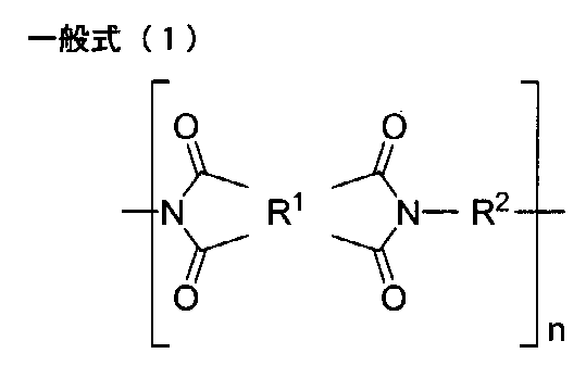
R1における芳香族環を有するテトラカルボン酸二無水物、及び、脂肪族環を有するテトラカルボン酸二無水物としては、前記と同様のものを用いることができる。
これらは単独でも、2種以上を混合して用いることもできる。
As the tetracarboxylic dianhydride having an aromatic ring in R 1 and the tetracarboxylic dianhydride having an aliphatic ring, those similar to the above can be used.
These may be used alone or in combination of two or more.
中でも、得られるポリイミドにおける光透過性の点、及び屈曲耐性及び表面硬度の点から、前記一般式(1)中のR1が、シクロヘキサンテトラカルボン酸二無水物残基、シクロペンタンテトラカルボン酸二無水物残基、ジシクロヘキサン-3,4,3’,4’-テトラカルボン酸二無水物残基、シクロブタンテトラカルボン酸二無水物残基、ピロメリット酸二無水物残基、3,3’,4,4’-ビフェニルテトラカルボン酸二無水物残基、2,2’,3,3’-ビフェニルテトラカルボン酸二無水物残基、4,4’-(ヘキサフルオロイソプロピリデン)ジフタル酸無水物残基、3,4’-(ヘキサフルオロイソプロピリデン)ジフタル酸無水物残基、3,3’-(ヘキサフルオロイソプロピリデン)ジフタル酸無水物残基、4,4’-オキシジフタル酸無水物残基、及び、3,4’-オキシジフタル酸無水物残基からなる群から選ばれる少なくとも1種の4価の基であることが好ましい。 Among them, R 1 in the general formula (1) is a residue of cyclohexanetetracarboxylic acid dianhydride, cyclopentanetetracarboxylic acid, from the viewpoint of light transmittance in the polyimide to be obtained, and bending resistance and surface hardness. Anhydride residue, Dicyclohexane-3,4,3 ′, 4′-tetracarboxylic acid dianhydride residue, cyclobutanetetracarboxylic acid dianhydride residue, pyromellitic acid dianhydride residue, 3,3 ′ 1,4,4'-biphenyltetracarboxylic acid dianhydride residue, 2,2 ', 3,3'-biphenyltetracarboxylic acid dianhydride residue, 4,4'-(hexafluoroisopropylidene) diphthalic anhydride Residue, 3,4 '-(hexafluoroisopropylidene) diphthalic anhydride residue, 3,3'-(hexafluoroisopropylidene) diphthalic anhydride residue, 4,4'-oxydiphthalic acid Anhydride residue, and is preferably at least one tetravalent group selected from the group consisting of 3,4'-oxydiphthalic anhydride residue.
特に光透過性が良い点から、テトラカルボン酸成分は、4,4’-(ヘキサフルオロイソプロピリデン)ジフタル酸無水物、3,4’-(ヘキサフルオロイソプロピリデン)ジフタル酸無水物、3,3’-(ヘキサフルオロイソプロピリデン)ジフタル酸無水物、4,4’-オキシジフタル酸無水物、及び、3,4’-オキシジフタル酸無水物からなる群から選ばれる少なくとも1種であることがより好ましい。 The tetracarboxylic acid component is particularly preferably 4,4 '-(hexafluoroisopropylidene) diphthalic anhydride, 3,4'-(hexafluoroisopropylidene) diphthalic anhydride, and 3,3 from the viewpoint of good light transmittance. More preferably, it is at least one selected from the group consisting of '-(hexafluoroisopropylidene) diphthalic anhydride, 4,4'-oxydiphthalic anhydride, and 3,4'-oxydiphthalic anhydride.
テトラカルボン酸成分としては、ピロメリット酸二無水物、3,3’,4,4’-ビフェニルテトラカルボン酸二無水物、及び、2,2’,3,3’-ビフェニルテトラカルボン酸二無水物からなる群から選択される少なくとも一種のような、得られるポリイミドに対し剛直性を向上するのに適したテトラカルボン酸群(グループA)と、シクロヘキサンテトラカルボン酸二無水物、シクロペンタンテトラカルボン酸二無水物、ジシクロヘキサン-3,4,3’,4’-テトラカルボン酸二無水物、シクロブタンテトラカルボン酸二無水物、4,4’-(ヘキサフルオロイソプロピリデン)ジフタル酸無水物、3,4’-(ヘキサフルオロイソプロピリデン)ジフタル酸無水物、3,3’-(ヘキサフルオロイソプロピリデン)ジフタル酸無水物、4,4’-オキシジフタル酸無水物、及び、3,4’-オキシジフタル酸無水物からなる群から選択される少なくとも一種のような光透過性を向上するのに適したテトラカルボン酸群(グループB)とを混合して用いることも好ましい。この場合、前記剛直性を向上するのに適したテトラカルボン酸群(グループA)と、光透過性を向上するのに適したテトラカルボン酸群(グループB)との含有比率は、光透過性を向上するのに適したテトラカルボン酸群(グループB)1モルに対して、前記剛直性を向上するのに適したテトラカルボン酸群(グループA)が0.05モル以上9モル以下であることが好ましく、更に0.1モル以上5モル以下であることが好ましく、より更に0.3モル以上4モル以下であることが好ましい。
中でも、前記グループBとしては、フッ素原子を含む、4,4’-(ヘキサフルオロイソプロピリデン)ジフタル酸無水物、及び3,4’-(ヘキサフルオロイソプロピリデン)ジフタル酸無水物の少なくとも一種を用いることが、得られるポリイミドにおける光透過性の向上の点から好ましい。
As a tetracarboxylic acid component, pyromellitic acid dianhydride, 3,3 ', 4,4'-biphenyltetracarboxylic acid dianhydride, and 2,2', 3,3'-biphenyltetracarboxylic acid dianhydride Tetracarboxylic acid group (group A) suitable for improving the rigidity of the resulting polyimide, such as at least one member selected from the group consisting of: cyclohexane tetracarboxylic acid dianhydride, cyclopentane tetracarbon Acid dianhydride, dicyclohexane-3,4,3 ′, 4′-tetracarboxylic acid dianhydride, cyclobutanetetracarboxylic acid dianhydride, 4,4 ′-(hexafluoroisopropylidene) diphthalic acid anhydride, 3 4,4 '-(hexafluoroisopropylidene) diphthalic anhydride, 3,3'-(hexafluoroisopropylidene) diphthalic anhydride, 4,4 ' A mixture of a tetracarboxylic acid group (group B) suitable for improving light transmittance such as at least one selected from the group consisting of -oxydiphthalic anhydride and 3,4'-oxydiphthalic anhydride It is also preferable to use as it is. In this case, the content ratio of the tetracarboxylic acid group (group A) suitable for improving the rigidity and the tetracarboxylic acid group (group B) suitable for improving the light transmittance is the light transmittance. 0.05 mol or more and 9 mol or less of tetracarboxylic acid group (group A) suitable for improving the rigidity with respect to 1 mol of tetracarboxylic acid group (group B) suitable for improving Is more preferably 0.1 to 5 moles, and still more preferably 0.3 to 4 moles.
Among them, at least one of 4,4 '-(hexafluoroisopropylidene) diphthalic anhydride and 3,4'-(hexafluoroisopropylidene) diphthalic anhydride containing a fluorine atom is used as the group B. It is preferable from the point of the improvement of the light transmittance in the polyimide obtained.
前記一般式(1)においてR2は、ジアミン残基である2価の基を表し、芳香族環又は脂肪族環を有するジアミン残基を含むものであれば特に制限はない。2価のジアミン残基としては、前記と同様のものを用いることができる。
これらは単独でも、2種以上を混合して用いることもできる。
In the above general formula (1), R 2 represents a divalent group which is a diamine residue, and is not particularly limited as long as it contains a diamine residue having an aromatic ring or an aliphatic ring. As a bivalent diamine residue, the thing similar to the above can be used.
These may be used alone or in combination of two or more.
R2に含まれる芳香族環又は脂肪族環を有するジアミン残基としても、それぞれ、前記と同様のものを用いることができる。
これらは単独でも、2種以上を混合して用いることもできる。
Even diamine residue having an aromatic ring or an aliphatic ring contained in R 2, may each, using the same as those described above.
These may be used alone or in combination of two or more.
中でも、光透過性と屈曲耐性の点及び表面硬度の点、低吸湿性の観点から、前記一般式(1)中のR2における芳香族環又は脂肪族環を有するジアミン残基が、trans-シクロヘキサンジアミン残基、trans-1,4-ビスメチレンシクロヘキサンジアミン残基、4,4’-ジアミノジフェニルスルホン残基、3,4’-ジアミノジフェニルスルホン残基、2,2-ビス(4-アミノフェニル)プロパン残基、3,3’-ビス(トリフルオロメチル)-4,4’-[(1,1,1,3,3,3-ヘキサフルオロプロパン-2,2-ジイル)ビス(4,1-フェニレンオキシ)]ジアニリン残基、2,2-ビス[3-(3-アミノフェノキシ)フェニル]-1,1,1,3,3,3-ヘキサフルオロプロパン残基、2,2-ビス[4-(4-アミノフェノキシ)フェニル]-1,1,1,3,3,3-ヘキサフルオロプロパン残基、及び下記一般式(2)で表される2価の基からなる群から選ばれる少なくとも1種の2価の基であることが好ましい。下記一般式(2)で表される2価の基としては、R3及びR4がパーフルオロアルキル基であることがより好ましい。 Among them, the diamine residue having an aromatic ring or an aliphatic ring in R 2 in the general formula (1) is trans-, from the viewpoint of light transmittance, bending resistance, surface hardness and low hygroscopicity. Cyclohexanediamine residue, trans-1,4-bismethylenecyclohexanediamine residue, 4,4'-diaminodiphenylsulfone residue, 3,4'-diaminodiphenylsulfone residue, 2,2-bis (4-aminophenyl) Propane residue, 3,3′-bis (trifluoromethyl) -4,4 ′-[(1,1,1,3,3,3-hexafluoropropane-2,2-diyl) bis (4, 1-phenyleneoxy)] dianiline residue, 2,2-bis [3- (3-aminophenoxy) phenyl] -1,1,1,3,3,3-hexafluoropropane residue, 2,2-bis [4- (4 At least one member selected from the group consisting of aminophenoxy) phenyl] -1,1,1,3,3,3-hexafluoropropane residues, and divalent groups represented by the following general formula (2) It is preferable that it is a valent group. As a divalent group represented by the following general formula (2), it is more preferable that R 3 and R 4 be a perfluoroalkyl group.

これらは単独でも、2種以上を混合して用いることもできる。
These may be used alone or in combination of two or more.
また、位相差を低減する点から、R2として主鎖にケイ素原子を有するジアミン残基が含まれることが好ましい。R2として好ましく使用することができる主鎖にケイ素原子を有するジアミン残基は、上述のとおりであるため、ここでは説明を省略する。 From the viewpoint of reducing the phase difference, it is preferable to include diamine residue having a silicon atom in the main chain as R 2. Since the diamine residue which has a silicon atom in the principal chain which can be preferably used as R 2 is as described above, the description is omitted here.
前記一般式(1)のR2として主鎖にケイ素原子を有するジアミン残基を含む場合には、前記一般式(1)のR2において、R2の総量の2.5モル%以上50モル%以下が、主鎖にケイ素原子を有するジアミン残基であり、R2の総量の50モル%以上97.5モル%以下が、ケイ素原子を有さず、芳香族環又は脂肪族環を有するジアミン残基であることにより、位相差が低減し、且つ、保護フィルムとして十分な表面硬度を有することができるため好ましい。前記一般式(1)のR2は、位相差が低減する点から、主鎖にケイ素原子を有するジアミン残基が、R2の総量の3.5モル%以上であることが好ましく、更に5モル%以上であることが好ましい。前記一般式(1)のR2は、位相差が低減する点から、主鎖にケイ素原子を有するジアミン残基が、R2の総量の10モル%以上、更に20モル%以上であっても良い。一方、前記一般式(1)のR2は、表面硬度と光透過性を向上する点から、主鎖にケイ素原子を有するジアミン残基が、R2の総量の45モル%以下であることが好ましく、更に40モル%以下であることが好ましい。
なお、R2の総量の2.5モル%以上50モル%以下が、主鎖にケイ素原子を有するジアミン残基であり、R2の総量の50モル%以上97.5モル%以下が、ケイ素原子を有さず、芳香族環又は脂肪族環を有するジアミン残基であることを満たせば、前記一般式(1)のR2に、主鎖にケイ素原子を有するジアミン残基及びケイ素原子を有さず芳香族環又は脂肪族環を有するジアミン残基とは異なる他のジアミン残基を含むことを妨げるものではない。当該他のジアミン残基は、R2の総量の10モル%以下であることが好ましく、更に5モル%以下であることが好ましく、より更に3モル%以下であることが好ましく、特に1モル%以下であることが好ましい。当該他のジアミン残基としては、例えば、ケイ素原子を有さず、且つ芳香族環又は脂肪族環を有しないジアミン残基等が挙げられる。
中でも、R2の総量の2.5モル%以上50モル%以下が、主鎖にケイ素原子を有するジアミン残基であり、R2の総量(100モル%)のうち、前記主鎖にケイ素原子を有するジアミン残基のモル%(xモル%)の残り(100%-x%)である50モル%以上99モル%以下が、ケイ素原子を有さず、芳香族環又は脂肪族環を有するジアミン残基であることが好ましい。
When containing a diamine residue having a silicon atom in the main chain as R 2 in the general formula (1), in R 2 in the general formula (1), 2.5 mol% to 50 mol of the total amount of R 2 % Or less is a diamine residue having a silicon atom in the main chain, and 50 to 97.5 mol% of the total amount of R 2 has no silicon atom and has an aromatic ring or an aliphatic ring By being a diamine residue, retardation is reduced and surface hardness sufficient as a protective film can be obtained, which is preferable. From the viewpoint of retardation reduction, R 2 in the general formula (1) is preferably a diamine residue having a silicon atom in the main chain is 3.5 mol% or more of the total amount of R 2 , and more preferably 5 It is preferable that it is mol% or more. Wherein R 2 in the general formula (1), from the point where the phase difference is reduced, the diamine residue having a silicon atom in the main chain, 10 mol% or more of the total amount of R 2, even more than 20 mol% good. On the other hand, R 2 in the general formula (1) is that the diamine residue having a silicon atom in the main chain is 45 mol% or less of the total amount of R 2 from the viewpoint of improving surface hardness and light transmittance. Preferably, it is more preferably 40 mol% or less.
Incidentally, 50 mol% 2.5 mol% or more of the total amount of R 2 or less, a diamine residue having a silicon atom in the main chain, or less 97.5 mol% 50 mol% or more of the total amount of R 2, silicon If it is satisfied that the diamine residue has no atom and has an aromatic ring or an aliphatic ring, a diamine residue having a silicon atom in the main chain and a silicon atom in R 2 of the general formula (1) are satisfied. It does not prevent including other diamine residue different from the diamine residue which does not have an aromatic ring or an aliphatic ring. The other diamine residue is preferably 10 mol% or less, more preferably 5 mol% or less, still more preferably 3 mol% or less, and particularly preferably 1 mol% or less of the total amount of R 2 It is preferable that it is the following. As the said other diamine residue, the diamine residue etc. which do not have a silicon atom and do not have an aromatic ring or an aliphatic ring are mentioned, for example.
Among them, more than 2.5 mol% of the total amount of R 2 50 mol% or less, a diamine residue having a silicon atom in the main chain, of the total amount of R 2 (100 mol%), silicon atoms in the main chain The remaining (100% -x%) of the remaining (100% -x%) of the mole% (x mole%) of the diamine residue having 50 has no silicon atom and has an aromatic ring or an aliphatic ring It is preferable that it is a diamine residue.
中でも、位相差を低減し、且つ、屈曲耐性及び表面硬度を両立させて向上する点から、前記一般式(1)におけるR2は、ケイ素原子を有しないジアミン残基、及び、主鎖にケイ素原子を1個又は2個有するジアミン残基から選ばれる少なくとも1種である2価の基を表し、R2の総量の2.5モル%以上50モル%以下が、主鎖にケイ素原子を1個又は2個有するジアミン残基であり、50モル%以上97.5モル%以下が、ケイ素原子を有さず、芳香族環又は脂肪族環を有するジアミン残基であることが好ましい。
中でも、R2の総量の2.5モル%以上50モル%以下が、主鎖にケイ素原子を1個又は2個有するジアミン残基であり、R2の総量(100モル%)のうち、前記主鎖にケイ素原子を1個又は2個有するジアミン残基のモル%(xモル%)の残余(100%-x%)である50モル%以上97.5モル%以下が、ケイ素原子を有さず、芳香族環又は脂肪族環を有するジアミン残基であることが好ましい。
前記一般式(1)のR2は、位相差を低減し、且つ、屈曲耐性を向上する点から、主鎖にケイ素原子を1個又は2個有するジアミン残基が、R2の総量の3モル%以上であることが好ましく、より更に5モル%以上であることが好ましく、ケイ素原子を有さず、芳香族環又は脂肪族環を有するジアミン残基は、上記に対応して、R2の総量の97モル%以下であることが好ましく、より更に95モル%以下であることが好ましい。
前記一般式(1)のR2は、位相差が低減する点から、主鎖にケイ素原子を1個又は2個有するジアミン残基が、R2の総量の10モル%以上、更に20モル%以上であっても良く、この場合、ケイ素原子を有さず、芳香族環又は脂肪族環を有するジアミン残基は、上記に対応して、R2の総量の90モル%以下、更に80モル%以下であって良い。
一方、前記一般式(1)のR2は、位相差を低減しながら、表面硬度と光透過性を向上する点から、主鎖にケイ素原子を1個又は2個有するジアミン残基が、R2の総量の45モル%以下であることが好ましく、更に40モル%以下であることが好ましく、ケイ素原子を有さず、芳香族環又は脂肪族環を有するジアミン残基は、上記に対応して、R2の総量の55モル%以上であることが好ましく、より更に60モル%以上であることが好ましい。
Among them, R 2 in the general formula (1) is a diamine residue having no silicon atom, and silicon in the main chain, from the viewpoint of reducing retardation and achieving a balance between bending resistance and surface hardness. Represents at least one divalent group selected from diamine residues having one or two atoms, wherein 2.5 to 50 mole% of the total amount of R 2 has one silicon atom in the main chain It is preferable that it is the diamine residue which has one or two pieces, and 50 mol% or more and 97.5 mol% or less is a diamine residue which does not have a silicon atom and has an aromatic ring or an aliphatic ring.
Among them, 50 mole% 2.5 mol% or more of the total amount of R 2 or less is a main one silicon atom in a chain or two with diamine residue, of the total amount of R 2 (100 mol%), the 50 mol% or more and 97.5 mol% or less, which is the remainder (100% -x%) of the mol% (x mol%) of the diamine residue having one or two silicon atoms in the main chain has a silicon atom Preferably, it is a diamine residue having an aromatic ring or an aliphatic ring.
From the viewpoint of reducing retardation and improving bending resistance, R 2 in the general formula (1) has 3 or less of the total amount of R 2 diamine residues having one or two silicon atoms in the main chain. It is preferable that it is mol% or more, more preferably 5 mol% or more, and the diamine residue having no silicon atom and having an aromatic ring or an aliphatic ring corresponds to the above, R 2 It is preferable that it is 97 mol% or less of the total of, and still more preferable that it is 95 mol% or less.
R 2 in the general formula (1), from the point where the phase difference is reduced, diamine residue having one or two silicon atoms in the main chain, at least 10 mole% of the total amount of R 2, further 20 mol% In this case, the diamine residue having no silicon atom and having an aromatic ring or an aliphatic ring is 90 mol% or less, and further 80 mol or less of the total amount of R 2 corresponding to the above. It may be less than%.
On the other hand, R 2 in the general formula (1) has a diamine residue having one or two silicon atoms in the main chain from the viewpoint of improving surface hardness and light transmittance while reducing retardation. It is preferably 45 mol% or less, more preferably 40 mol% or less of the total amount of 2 , and diamine residues having no silicon atom and having an aromatic ring or an aliphatic ring correspond to the above. Te is preferably at least 55 mol% of the total amount of R 2, is preferably more further 60 mol% or more.
前記一般式(1)で表される構造において、nは繰り返し単位数を表し、1以上である。
ポリイミドにおける繰り返し単位数nは、適宜選択されれば良く、特に限定されない。
平均繰り返し単位数は、通常10~2000であり、更に15~1000であることが好ましい。
なお、各繰り返し単位におけるR1は各々同一であっても異なっていても良く、各繰り返し単位におけるR2は各々同一でも異なっていても良い。
In the structure represented by the general formula (1), n represents the number of repeating units and is 1 or more.
The number n of repeating units in the polyimide may be appropriately selected, and is not particularly limited.
The average number of repeating units is usually 10 to 2,000, preferably 15 to 1,000.
R 1 in each repeating unit may be the same or different, and R 2 in each repeating unit may be the same or different.
また、前記一般式(1)で表される構造を有するポリイミドは、フィルムとした際の強度及び屈曲耐性の点から、数平均分子量が10000以上であることが好ましく、20000以上であることがより好ましく、30000以上であることがより更に好ましく、50000以上であることが特に好ましい。上限は特に限定はされないが、合成が容易であり、入手し易い点から、10000000以下であることが好ましく、更に500000以下であることが好ましい。
なお、ポリイミドの数平均分子量は、後述するポリイミド前駆体の数平均分子量と同様にして測定することができる。
The polyimide having a structure represented by the general formula (1) preferably has a number average molecular weight of 10000 or more, more preferably 20000 or more, from the viewpoint of strength and bending resistance when formed into a film. Preferably, it is more preferably 30000 or more, and particularly preferably 50000 or more. The upper limit is not particularly limited, but is preferably 10,000,000 or less, more preferably 500,000 or less, from the viewpoint of easy synthesis and easy availability.
The number average molecular weight of the polyimide can be measured in the same manner as the number average molecular weight of the polyimide precursor described later.
また、前記一般式(1)で表される構造を有するポリイミドは、フィルムとした際の強度及び屈曲耐性の点から、重量平均分子量が、20000以上であることが好ましく、30000以上であることがより好ましく、40000以上であることがより更に好ましく、80000以上であることが特に好ましい。上限は特に限定はされないが、合成が容易であり、入手し易い点から、10000000以下であることが好ましく、更に500000以下であることが好ましい。
ポリイミドの重量平均分子量は、ゲル浸透クロマトグラフィー(GPC)によって測定できる。具体的には、ポリイミドを0.1重量%の濃度のN-メチルピロリドン(NMP)溶液とし、展開溶媒は、含水量500ppm以下の30mmol%LiBr-NMP溶液を用い、東ソー製GPC装置(HLC-8120、使用カラム:SHODEX製GPC LF-804)を用い、サンプル打ち込み量50μL、溶媒流量0.4mL/分、37℃の条件で測定を行う。重量平均分子量は、サンプルと同濃度のポリスチレン標準サンプルを基準に求める。
The polyimide having the structure represented by the general formula (1) preferably has a weight average molecular weight of 20000 or more, and 30000 or more, from the viewpoint of strength and bending resistance when formed into a film. More preferably, it is 40000 or more, still more preferably 80000 or more. The upper limit is not particularly limited, but is preferably 10,000,000 or less, more preferably 500,000 or less, from the viewpoint of easy synthesis and easy availability.
The weight average molecular weight of the polyimide can be measured by gel permeation chromatography (GPC). Specifically, polyimide is used as an N-methyl pyrrolidone (NMP) solution with a concentration of 0.1% by weight, and a developing solvent is a 30 mmol% LiBr-NMP solution with a water content of 500 ppm or less. 8120, column used: GPC LF-804 manufactured by SHODEX, and measurement is carried out under the conditions of a sample loading amount of 50 μL, a solvent flow rate of 0.4 mL / min, and 37 ° C. The weight average molecular weight is determined based on a polystyrene standard sample at the same concentration as the sample.
本開示に用いられるポリイミドは、本開示の効果が損なわれない限り、ポリアミド構造など、その一部にポリイミドとは異なる構造を有していても良い。
また、本開示に用いられるポリイミドは、本開示の効果が損なわれない限り、その一部に前記一般式(1)で表される構造とは異なる構造を有していても良い。本開示に用いられるポリイミドは、前記一般式(1)で表される構造が、ポリイミドの全繰り返し単位数の95%以上であることが好ましく、98%以上であることがより好ましく、100%であることがより更に好ましい。
前記一般式(1)で表される構造とは異なる構造としては、例えば、芳香族環又は脂肪族環を有しないテトラカルボン酸残基等が含まれる場合や、ポリアミド構造が挙げられる。
含んでいても良いポリアミド構造としては、例えば、トリメリット酸無水物のようなトリカルボン酸残基を含むポリアミドイミド構造や、テレフタル酸のようなジカルボン酸残基を含むポリアミド構造が挙げられる。
The polyimide used in the present disclosure may have a structure different from the polyimide in a part thereof, such as a polyamide structure, as long as the effects of the present disclosure are not impaired.
Moreover, the polyimide used for this indication may have a structure different from the structure represented by the said General formula (1) in the one, unless the effect of this indication is impaired. In the polyimide used in the present disclosure, the structure represented by the general formula (1) is preferably 95% or more, more preferably 98% or more, and more preferably 100% of the total number of repeating units of the polyimide. Even more preferred is
As a structure different from the structure represented by the said General formula (1), the case where the tetracarboxylic-acid residue etc. which do not have an aromatic ring or an aliphatic ring etc. are contained, for example, and a polyamide structure are mentioned.
Examples of the polyamide structure which may be contained include a polyamideimide structure containing a tricarboxylic acid residue such as trimellitic anhydride, and a polyamide structure containing a dicarboxylic acid residue such as terephthalic acid.
ポリイミド中の各繰り返し単位の含有割合、各テトラカルボン酸残基や各ジアミン残基の含有割合(モル%)は、ポリイミド製造時には仕込みの分子量から求めることができる。また、ポリイミド中の各テトラカルボン酸残基や各ジアミン残基の含有割合(モル%)は、上記と同様に、アルカリ水溶液、又は、超臨界メタノールにより分解して得られたポリイミドの分解物について、高速液体クロマトグラフィー、ガスクロマトグラフ質量分析計、NMR、元素分析、XPS/ESCA及びTOF-SIMSを用いて求めることができる。 The content ratio of each repeating unit in the polyimide, and the content ratio (mol%) of each tetracarboxylic acid residue and each diamine residue can be determined from the molecular weight of the feed at the time of polyimide production. In addition, the content ratio (mol%) of each tetracarboxylic acid residue and each diamine residue in the polyimide is the decomposition product of the polyimide obtained by decomposition with an alkaline aqueous solution or supercritical methanol as described above. High performance liquid chromatography, gas chromatograph mass spectrometer, NMR, elemental analysis, XPS / ESCA and TOF-SIMS.
2.添加剤
本開示のポリイミドフィルムは、前記ポリイミドの他に、必要に応じて更に添加剤を含有していてもよい。前記添加剤としては、例えば、無機粒子、巻き取りを円滑にするためのシリカフィラーや、製膜性や脱泡性を向上させる界面活性剤等が挙げられる。
2. Additives The polyimide film of the present disclosure may further contain an additive, if necessary, in addition to the polyimide. Examples of the additive include inorganic particles, a silica filler for facilitating winding, and a surfactant for improving film forming properties and defoaming properties.
3.ポリイミドフィルムの特性
本開示のポリイミドフィルムにおける、前記tanδ曲線、全光線透過率については、前述したのでここでの記載を省略する。
3. Properties of Polyimide Film Since the tan δ curve and the total light transmittance of the polyimide film of the present disclosure have been described above, the description thereof is omitted here.
また、本開示のポリイミドフィルムでは、位相差が低減されている。位相差の測定値は膜厚の影響を受けることから、測定値のみでポリイミドフィルムの位相差の優劣を評価できない場合があるため、通常、位相差を膜厚で除することにより算出される複屈折率に変換して評価する。
本開示のポリイミドフィルムにおいて、波長590nmにおける膜厚方向の複屈折率は、より小さい方が好ましく、中でも、0.008未満であることが好ましく、0.005以下であることが更に好ましく、0.004以下であることがより更に好ましい。
位相差が低減された本開示のポリイミドフィルムは、ディスプレイ用表面材として用いた場合に、ディスプレイの表示品質の低下を抑制することができる。
なお、本開示のポリイミドフィルムの波長590nmにおける膜厚方向の位相差及び複屈折率は、以下のように求めることができる。
まず、位相差測定装置(例えば、王子計測機器株式会社製、製品名「KOBRA-WR」)を用いて、25℃、波長590nmの光で、ポリイミドフィルムの膜厚方向位相差値(Rth)を測定する。膜厚方向位相差値(Rth)は、0度入射の位相差値と、斜め40度入射の位相差値を測定し、これらの位相差値から膜厚方向位相差値Rthを算出する。前記斜め40度入射の位相差値は、位相差フィルムの法線から40度傾けた方向から、波長590nmの光を位相差フィルムに入射させて測定する。
ポリイミドフィルムの膜厚方向の複屈折率は、式:Rth/dに代入して求めることができる。前記dは、ポリイミドフィルムの膜厚(nm)を表す。
なお、膜厚方向位相差値は、フィルムの面内方向における遅相軸方向(フィルム面内方向における屈折率が最大となる方向)の屈折率をnx、フィルム面内における進相軸方向(フィルム面内方向における屈折率が最小となる方向)の屈折率をny、及びフィルムの膜厚方向の屈折率をnzとしたときに、Rth[nm]={(nx+ny)/2-nz}×dと表すことができる。
Moreover, in the polyimide film of this indication, the phase difference is reduced. Since the measured value of the retardation is affected by the film thickness, it may not be possible to evaluate the superiority or inferiority of the retardation of the polyimide film only by the measured value. Therefore, it is usually calculated by dividing the retardation by the film thickness. Convert to refractive index and evaluate.
In the polyimide film of the present disclosure, the birefringence in the film thickness direction at a wavelength of 590 nm is preferably smaller, and more preferably less than 0.008, and still more preferably 0.005 or less. It is even more preferable that it is 004 or less.
When the polyimide film of the present disclosure in which the retardation is reduced is used as a surface material for a display, it is possible to suppress a decrease in display quality of the display.
The retardation in the film thickness direction at a wavelength of 590 nm and the birefringence of the polyimide film of the present disclosure can be determined as follows.
First, a retardation value (Rth) in the film thickness direction of a polyimide film is measured with light at a wavelength of 590 nm at 25 ° C. using a retardation measurement apparatus (for example, product name “KOBRA-WR” manufactured by Oji Scientific Instruments Co., Ltd.) taking measurement. The film thickness direction retardation value (Rth) measures a retardation value at 0 degree incidence and a retardation value at 40 degree oblique incidence, and calculates a film thickness direction retardation value Rth from these retardation values. The retardation value of the oblique 40-degree incidence is measured by causing light of wavelength 590 nm to be incident on the retardation film from a direction inclined 40 degrees from the normal of the retardation film.
The birefringence in the film thickness direction of the polyimide film can be determined by substituting it into the formula: Rth / d. Said d represents the film thickness (nm) of a polyimide film.
In the film thickness direction retardation value, the refractive index of the slow axis direction in the in-plane direction of the film (the direction in which the refractive index in the film in-plane direction is maximum) is nx, and the fast axis direction (film Rth [nm] = {(nx + ny) / 2-nz} × d, where ny is the refractive index in the direction in which the refractive index in the in-plane direction is minimum, and nz is the refractive index in the film thickness direction of the film. It can be expressed as.
また、本開示のポリイミドフィルムは、JIS K7373-2006に準拠して算出される黄色度(YI値)が、30以下であることが好ましい。黄色度(YI値)が30以下である場合には、黄色味の着色が抑制され、光透過性が向上し、良好なガラス代替材料となり得る。前記JIS K7373-2006に準拠して算出される黄色度(YI値)は、20以下であることが好ましく、15以下であることが更に好ましく、10以下であることがより更に好ましい。
本開示のポリイミドフィルムは、厚み5μm以上100μm以下において、前記JIS K7373-2006に準拠して算出される黄色度(YI値)が30以下であることが好ましく、20以下であることが更に好ましく、15以下であることがより更に好ましく、10以下であることが特に好ましい。
また、本開示のポリイミドフィルムは、厚み50μm±5μmにおいて、前記JIS K7373-2006に準拠して算出される黄色度(YI値)が、10以下であることが好ましく、7以下であることが更に好ましく、5以下であることがより更に好ましい。
なお、黄色度(YI値)は、JIS K7373-2006に準拠して、紫外可視近赤外分光光度計(例えば、日本分光(株) V-7100)を用い、分光測色方法により、補助イルミナントC、2度視野を用いて、250nm以上800nm以下の範囲を1nm間隔で測定される透過率をもとに、XYZ表色系における三刺激値X,Y,Zを求め、そのX,Y,Zの値から以下の式より算出することができる。
YI=100(1.2769X-1.0592Z)/Y
なお、ある厚みの黄色度の測定値から、異なる厚みの黄色度は、ある特定の膜厚のサンプルの250nm以上800nm以下の間の1nm間隔で測定された各波長における各透過率について、前記全光線透過率と同様にランベルトベールの法則により異なる厚みの各波長における各透過率の換算値を求め、それを元に算出し用いることができる。
The polyimide film of the present disclosure preferably has a yellowness (YI value) of 30 or less calculated in accordance with JIS K7373-2006. When the degree of yellowness (YI value) is 30 or less, coloring of yellowish color is suppressed, light transmittance is improved, and a good glass substitute material can be obtained. The yellowness (YI value) calculated in accordance with JIS K7373-2006 is preferably 20 or less, more preferably 15 or less, and still more preferably 10 or less.
The polyimide film of the present disclosure preferably has a yellowness (YI value) calculated according to JIS K7373-2006 at a thickness of 5 μm to 100 μm, preferably 30 or less, and more preferably 20 or less. It is further more preferable that it is 15 or less, and it is especially preferable that it is 10 or less.
The polyimide film of the present disclosure preferably has a yellowness (YI value) of 10 or less, preferably 7 or less, at a thickness of 50 μm ± 5 μm, which is calculated according to the aforementioned JIS K7373-2006. Preferably, it is 5 or less.
The degree of yellowness (YI value) can be determined by the spectrophotometric method using an ultraviolet visible near infrared spectrophotometer (for example, JASCO Corporation V-7100) in accordance with JIS K7373-2006. C, tristimulus values X, Y, Z in the XYZ color system are determined based on the transmittance measured at 1 nm intervals in the range of 250 nm or more and 800 nm or less using a 2 ° field of view, and the X, Y, Z It can be calculated from the value of Z according to the following equation.
YI = 100 (1.2769X-1.0592Z) / Y
In addition, from the measured value of the degree of yellowness of a certain thickness, the degree of yellowness of a different thickness is the total of the respective transmittances at each wavelength measured at 1 nm intervals between 250 nm and 800 nm or less of the sample of a specific thickness Similar to the light transmittance, a converted value of each transmittance at each wavelength of different thickness can be obtained according to the Lambert-Beer's law, and it can be calculated and used based on it.
本開示のポリイミドフィルムのヘイズ値は、光透過性の点から、2.0以下であることが好ましく、1.5以下であることが更に好ましく、1.0以下であることがより更に好ましい。当該ヘイズ値は、ポリイミドフィルムの厚みが5μm以上100μm以下において達成できることが好ましい。
前記ヘイズ値は、JIS K-7105に準拠した方法で測定することができ、例えば村上色彩技術研究所製のヘイズメーターHM150により測定することができる。
The haze value of the polyimide film of the present disclosure is preferably 2.0 or less, more preferably 1.5 or less, and still more preferably 1.0 or less from the viewpoint of light transmittance. The haze value can preferably be achieved when the thickness of the polyimide film is 5 μm or more and 100 μm or less.
The haze value can be measured by a method according to JIS K-7105, and can be measured, for example, by a haze meter HM150 manufactured by Murakami Color Research Laboratory.
また、本開示のポリイミドフィルムは、15mm×40mmの試験片をJIS K7127に準拠し、引張り速度を8mm/分、チャック間距離を20mmとして測定する25℃における引張弾性率が、表面硬度の点から1.8GPa以上であることが好ましく、屈曲耐性の点から5.0GPa以下であってよい。屈曲耐性及び表面硬度の点から、更に、2.0GPa以上4.0GPa以下であることが好ましく、より更に、2.0GPa以上3.5GPa以下であることが好ましい。
前記引張弾性率は、引張り試験機(例えば島津製作所製:オートグラフAG-X 1N、ロードセル:SBL-1KN)を用い、幅15mm×長さ40mmの試験片をポリイミドフィルムから切り出して、25℃で、引張り速度8mm/分、チャック間距離は20mmとして測定することができる。前記引張弾性率を求める際のポリイミドフィルムは厚みが55μm±5μmであることが好ましい。
In addition, the polyimide film of the present disclosure measures 15 mm × 40 mm test pieces in accordance with JIS K7127, and the tensile modulus at 25 ° C. measured at a tensile speed of 8 mm / min and a distance between chucks of 20 mm is the surface hardness. It is preferably 1.8 GPa or more, and may be 5.0 GPa or less from the viewpoint of bending resistance. From the viewpoint of bending resistance and surface hardness, it is more preferable that the energy density be 2.0 GPa or more and 4.0 GPa or less, and still more preferable that the energy density be 2.0 GPa or more and 3.5 GPa or less.
The tensile modulus is measured at 25 ° C. by using a tensile tester (for example, Shimadzu Corporation autograph AG-X 1N, load cell: SBL-1KN) and cutting a test piece 15 mm wide × 40 mm long from the polyimide film. , And the distance between chucks can be measured as 20 mm. The polyimide film at the time of obtaining the tensile elastic modulus preferably has a thickness of 55 μm ± 5 μm.
本開示のポリイミドフィルムにおいて、鉛筆硬度は6B以上であってもよいが、表面硬度の点からはB以上であることがより好ましく、HB以上であることがより更に好ましい。
前記ポリイミドフィルムの鉛筆硬度は、測定サンプルを温度25℃、相対湿度60%の条件で2時間調湿した後、JIS-S-6006が規定する試験用鉛筆を用いて、JIS K5600-5-4(1999)に規定する鉛筆硬度試験(0.98N荷重)をフィルム表面に行い、傷がつかない最も高い鉛筆硬度を評価することにより行うことができる。試験機としては、例えば東洋精機(株)製 鉛筆引っかき塗膜硬さ試験機を用いることができる。
In the polyimide film of the present disclosure, the pencil hardness may be 6 B or more, but it is more preferably B or more, and even more preferably HB or more from the viewpoint of surface hardness.
The pencil hardness of the polyimide film is adjusted according to JIS K 5600-5-4 using a test pencil specified in JIS-S-6006 after conditioning the measurement sample under the conditions of temperature 25 ° C. and
4.ポリイミドフィルムの構成
本開示のポリイミドフィルムの厚さは、用途により適宜選択されれば良いが、強度の点から、1μm以上であることが好ましく、更に5μm以上であることが好ましく、より更に10μm以上であることが好ましい。
4. Configuration of Polyimide Film Although the thickness of the polyimide film of the present disclosure may be appropriately selected depending on the application, it is preferably 1 μm or more, more preferably 5 μm or more, and still more 10 μm or more from the viewpoint of strength. Is preferred.
また、本開示のポリイミドフィルムには、例えば、けん化処理、グロー放電処理、コロナ放電処理、紫外線処理、火炎処理等の表面処理が施されていてもよい。 In addition, the polyimide film of the present disclosure may be subjected to surface treatment such as saponification treatment, glow discharge treatment, corona discharge treatment, ultraviolet treatment, flame treatment, and the like.
5.ポリイミドフィルムの製造方法
本開示のポリイミドフィルムの製造方法は、前記本開示のポリイミドフィルムを製造できる方法であれば特に制限はないが、例えば、前述のように、ポリイミド前駆体であるポリアミド酸を加熱によりイミド化する方法であることが好ましく、下記第1の製造方法が好ましい。
<第1の製造方法>
本開示のポリイミドフィルムの製造方法としては、第1の製造方法として、
ポリイミド前駆体であるポリアミド酸と、有機溶剤とを含むポリイミド前駆体樹脂組成物を調製する工程(以下、ポリイミド前駆体樹脂組成物調製工程という)と、
前記ポリイミド前駆体樹脂組成物を支持体に塗布して、ポリイミド前駆体樹脂塗膜を形成する工程(以下、ポリイミド前駆体樹脂塗膜形成工程という)と、
加熱をすることにより、前記ポリイミド前駆体をイミド化する工程(以下、熱イミド化工程という)と、を含むポリイミドフィルムの製造方法が挙げられる。
5. Method for Producing Polyimide Film The method for producing the polyimide film of the present disclosure is not particularly limited as long as it can produce the polyimide film of the present disclosure, but, for example, as described above, heating the polyamic acid which is a polyimide precursor It is preferable that it is the method of imidating by this, and the following 1st manufacturing method is preferable.
<First manufacturing method>
As a method for producing the polyimide film of the present disclosure, as a first production method,
Preparing a polyimide precursor resin composition containing a polyamic acid which is a polyimide precursor and an organic solvent (hereinafter referred to as a polyimide precursor resin composition preparation step);
Applying the polyimide precursor resin composition to a support to form a polyimide precursor resin coating film (hereinafter referred to as a polyimide precursor resin coating film forming step);
And a step of imidizing the polyimide precursor by heating (hereinafter referred to as a thermal imidization step).
本開示のポリイミドフィルムの製造方法においては、更に、前記ポリイミド前駆体樹脂塗膜、及び、前記ポリイミド前駆体樹脂塗膜をイミド化したイミド化後塗膜の少なくとも一方を延伸する工程(以下、延伸工程という)を有していてもよい。
以下、熱イミド化工程を有する本開示のポリイミドフィルムの製造方法の例について工程ごとに詳細に説明する。
In the method of producing a polyimide film of the present disclosure, a step of stretching at least one of the polyimide precursor resin coating film and the post-imidized coating film obtained by imidizing the polyimide precursor resin coating film (hereinafter, stretching It may have a process).
Hereinafter, the example of the manufacturing method of the polyimide film of this indication which has a heat | fever imidation process is demonstrated in detail for every process.
(1)ポリイミド前駆体樹脂組成物調製工程
ポリイミド前駆体樹脂組成物は、ポリイミド前駆体と、有機溶剤とを含有し、必要に応じて添加剤等を含有していてもよい。前記ポリイミド前駆体としては、例えば、下記一般式(1’)で表されるポリイミド前駆体が挙げられる。前記一般式(1’)で表されるポリイミド前駆体は、前記一般式(1’)のR1におけるテトラカルボン酸残基となるテトラカルボン酸成分と、前記一般式(1’)のR2におけるジアミン残基となるジアミン成分との重合によって得られるポリアミド酸である。
(1) Polyimide precursor resin composition preparation process A polyimide precursor resin composition contains a polyimide precursor and an organic solvent, and may contain an additive etc. if needed. As said polyimide precursor, the polyimide precursor represented by following General formula (1 ') is mentioned, for example. The polyimide precursor represented by the general formula (1 ′) is a tetracarboxylic acid component to be a tetracarboxylic acid residue in R 1 of the general formula (1 ′), and R 2 of the general formula (1 ′) Is a polyamic acid obtained by polymerization with a diamine component to be a diamine residue.
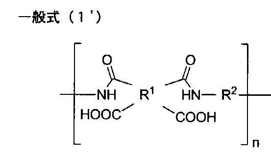
前記一般式(1’)で表されるポリイミド前駆体は、数平均分子量、または重量平均分子量の少なくともいずれかが、フィルムとした際の強度の点から、10000以上であることが好ましく、更に20000以上であることが好ましい。一方、平均分子量が大きすぎると、高粘度となり、ろ過などの作業性が低下の恐れがある点から、10000000以下であることが好ましく、更に500000以下であることが好ましい。
ポリイミド前駆体の数平均分子量は、NMR(例えば、BRUKER製、AVANCEIII)により求めることができる。例えば、ポリイミド前駆体溶液をガラス板に塗布して100℃で5分乾燥後、固形分10mgをジメチルスルホキシド-d6溶媒7.5mlに溶解し、NMR測定を行い、芳香族環に結合している水素原子のピーク強度比から数平均分子量を算出することができる。
ポリイミド前駆体の重量平均分子量は、ゲル浸透クロマトグラフィー(GPC)によって測定できる。
ポリイミド前駆体を0.5重量%の濃度のN-メチルピロリドン(NMP)溶液とし、展開溶媒は、含水量500ppm以下の10mmol%LiBr-NMP溶液を用い、東ソー製GPC装置(HLC-8120、使用カラム:SHODEX製GPC LF-804)を用い、サンプル打ち込み量50μL、溶媒流量0.5mL/分、40℃の条件で測定を行う。重量平均分子量は、サンプルと同濃度のポリスチレン標準サンプルを基準に求める。
The polyimide precursor represented by the general formula (1 ′) preferably has a number average molecular weight or weight average molecular weight of at least 10000 in terms of strength when formed into a film, and more preferably 20000. It is preferable that it is more than. On the other hand, if the average molecular weight is too large, the viscosity will be high, and there is a possibility that the workability such as filtration may be reduced, so it is preferably 10,000,000 or less, more preferably 500,000 or less.
The number average molecular weight of the polyimide precursor can be determined by NMR (for example, AVANCE III manufactured by BRUKER). For example, after applying a polyimide precursor solution to a glass plate and drying at 100 ° C. for 5 minutes, 10 mg of solid content is dissolved in 7.5 ml of dimethylsulfoxide-d6 solvent, NMR measurement is performed, and it is bonded to an aromatic ring The number average molecular weight can be calculated from the peak intensity ratio of hydrogen atoms.
The weight average molecular weight of the polyimide precursor can be measured by gel permeation chromatography (GPC).
A polyimide precursor is N-methyl pyrrolidone (NMP) solution with a concentration of 0.5% by weight, and a developing solvent is a Tosoh GPC apparatus (HLC-8120, using a 10 mmol% LiBr-NMP solution with a water content of 500 ppm or less) Column: Measurement is carried out using a sample injection amount of 50 μL, solvent flow rate of 0.5 mL / min, and 40 ° C. using GPC LF-804 manufactured by SHODEX. The weight average molecular weight is determined based on a polystyrene standard sample at the same concentration as the sample.
前記ポリイミド前駆体溶液は、上述のテトラカルボン酸二無水物と、上述のジアミンとを、溶剤中で反応させて得られる。ポリイミド前駆体(ポリアミド酸)の合成に用いる溶剤としては、上述のテトラカルボン酸二無水物及びジアミンを溶解可能であれば特に制限はなく、例えば非プロトン性極性溶剤または水溶性アルコール系溶剤等を用い得る。本開示においては、中でも、N-メチル-2-ピロリドン、N,N-ジメチルホルムアミド、N,N-ジメチルアセトアミド、ジメチルスルホキシド、ヘキサメチルホスホルアミド、1,3-ジメチル-2-イミダゾリジノン等の窒素原子を含む有機溶剤;γ-ブチロラクトン等を用いることが好ましい。中でも、前記ポリイミド前駆体溶液(ポリアミド酸溶液)をそのままポリイミド前駆体樹脂組成物の調製に用いる場合に、ポリイミド前駆体樹脂組成物が後述する無機粒子を含有する場合は、無機粒子の溶解を抑制する点から、窒素原子を含む有機溶剤を用いることが好ましく、中でも、N,N-ジメチルアセトアミド、N-メチル-2-ピロリドンもしくはこれらの組み合わせを用いることが好ましい。なお、有機溶剤とは、炭素原子を含む溶剤である。 The polyimide precursor solution can be obtained by reacting the above-described tetracarboxylic acid dianhydride and the above-described diamine in a solvent. The solvent used for synthesis of the polyimide precursor (polyamic acid) is not particularly limited as long as it can dissolve the above-described tetracarboxylic acid dianhydride and diamine, and, for example, an aprotic polar solvent or a water-soluble alcohol solvent etc. It can be used. In the present disclosure, among others, N-methyl-2-pyrrolidone, N, N-dimethylformamide, N, N-dimethylacetamide, dimethylsulfoxide, hexamethylphosphoramide, 1,3-dimethyl-2-imidazolidinone and the like It is preferable to use an organic solvent containing a nitrogen atom of: γ-butyrolactone or the like. In particular, when the polyimide precursor solution (polyamic acid solution) is used as it is for preparation of a polyimide precursor resin composition, the dissolution of inorganic particles is suppressed when the polyimide precursor resin composition contains inorganic particles described later. From the point of view, it is preferable to use an organic solvent containing a nitrogen atom, and it is preferable to use N, N-dimethylacetamide, N-methyl-2-pyrrolidone or a combination thereof. In addition, an organic solvent is a solvent containing a carbon atom.
また、前記ポリイミド前駆体溶液を、2種以上のジアミンを組み合わせて調製する場合には、少なくとも2種のジアミンの混合溶液に酸二無水物を添加し、ポリアミド酸を合成してもよいし、少なくとも2種のジアミン成分を適切なモル比で段階を踏んで反応液に添加し、ある程度、各原料が高分子鎖へ組み込まれるシーケンスをコントロールしてもよい。
たとえば、主鎖にケイ素原子を有するジアミンが溶解された反応液に、主鎖にケイ素原子を有するジアミンの0.5等量のモル比の酸二無水物を投入し反応させることで、酸二無水物の両端に主鎖にケイ素原子を有するジアミンが反応したアミド酸を合成し、そこへ、残りのジアミンを全部、又は一部投入し、酸二無水物を加えてポリアミド酸を重合しても良い。この方法で重合すると、主鎖にケイ素原子を有するジアミンが1つの酸二無水物を介して、連結した形でポリアミド酸の中に導入される。
このような方法でポリアミド酸を重合することは、主鎖にケイ素原子を有するアミド酸の位置関係がある程度特定され、表面硬度を維持しつつ低位相差な膜を得易い点から好ましい。
Moreover, when preparing the said polyimide precursor solution combining 2 or more types of diamine, an acid dianhydride may be added to the mixed solution of at least 2 types of diamine, and a polyamic acid may be synthesize | combined, At least two diamine components may be added to the reaction solution in stages at appropriate molar ratios to control, in part, the sequence in which each source is incorporated into the polymer chain.
For example, an acid dianhydride having a molar ratio of 0.5 equivalent of a diamine having a silicon atom in the main chain is charged with a reaction solution in which a diamine having a silicon atom in the main chain is dissolved, and then reacted. An amic acid in which a diamine having a silicon atom at the main chain at both ends of the anhydride is reacted is synthesized, into which the remaining diamine is fully or partially introduced, and an acid dianhydride is added to polymerize the polyamic acid. Also good. When polymerized in this manner, diamines having a silicon atom in the main chain are introduced into the polyamic acid in a linked form via one acid dianhydride.
It is preferable to polymerize the polyamic acid by such a method because it is specified to some extent in the positional relationship of the amic acid having a silicon atom in the main chain, and a film with low retardation can be easily obtained while maintaining the surface hardness.
前記ポリイミド前駆体溶液(ポリアミド酸溶液)中のジアミンのモル数をX、テトラカルボン酸二無水物のモル数をYとしたとき、Y/Xを0.9以上1.1以下とすることが好ましく、0.95以上1.05以下とすることがより好ましく、0.97以上1.03以下とすることがさらに好ましく、0.99以上1.01以下とすることが特に好ましい。このような範囲とすることにより得られるポリアミド酸の分子量(重合度)を適度に調整することができる。
重合反応の手順は、公知の方法を適宜選択して用いることができ、特に限定されない。
また、合成反応により得られたポリイミド前駆体溶液をそのまま用い、そこに必要に応じて他の成分を混合しても良いし、ポリイミド前駆体溶液の溶剤を乾燥させ、別の溶剤に溶解して用いても良い。
Assuming that the number of moles of diamine in the polyimide precursor solution (polyamic acid solution) is X and the number of moles of tetracarboxylic acid dianhydride is Y, Y / X should be 0.9 or more and 1.1 or less. Preferably, it is more preferably 0.95 or more and 1.05 or less, still more preferably 0.97 or more and 1.03 or less, and particularly preferably 0.99 or more and 1.01 or less. The molecular weight (polymerization degree) of the polyamic acid obtained by setting it as such a range can be adjusted moderately.
The procedure of the polymerization reaction can be selected appropriately from known methods, and is not particularly limited.
Alternatively, the polyimide precursor solution obtained by the synthesis reaction may be used as it is, and if necessary, other components may be mixed, or the solvent of the polyimide precursor solution may be dried and dissolved in another solvent. You may use.
前記ポリイミド前駆体溶液の25℃での粘度は、均一な塗膜及びポリイミドフィルムを形成する点から、500cps以上200000cps以下であることが好ましい。
ポリイミド前駆体溶液の粘度は、粘度計(例えば、TVE-22HT、東機産業株式会社)を用いて、25℃で測定することができる。
The viscosity at 25 ° C. of the polyimide precursor solution is preferably 500 cps or more and 200,000 cps or less from the viewpoint of forming a uniform coating film and polyimide film.
The viscosity of the polyimide precursor solution can be measured at 25 ° C. using a viscometer (eg, TVE-22HT, Toki Sangyo Co., Ltd.).
前記ポリイミド前駆体樹脂組成物は、必要に応じて添加剤を含有していてもよい。前記添加剤としては、例えば、巻き取りを円滑にするためのシリカフィラーや、製膜性や脱泡性を向上させる界面活性剤等が挙げられ、前述のポリイミドフィルムにおいて説明したものと同様のものを用いることができる。 The said polyimide precursor resin composition may contain the additive as needed. Examples of the additive include a silica filler for facilitating winding, a surfactant for improving the film forming property and the defoaming property, and the like, and the same as those described in the above-mentioned polyimide film Can be used.
前記ポリイミド前駆体樹脂組成物に用いられる有機溶剤は、前記ポリイミド前駆体が溶解可能であれば特に制限はない。例えば、N-メチル-2-ピロリドン、N,N-ジメチルホルムアミド、N,N-ジメチルアセトアミド、ジメチルスルホキシド、ヘキサメチルホスホルアミド、1,3-ジメチル-2-イミダゾリジノン等の窒素原子を含む有機溶剤;γ-ブチロラクトン等を用いることができるが、中でも、前述した理由により窒素原子を含む有機溶剤を用いることが好ましい。 The organic solvent used for the polyimide precursor resin composition is not particularly limited as long as the polyimide precursor can be dissolved. For example, it contains a nitrogen atom such as N-methyl-2-pyrrolidone, N, N-dimethylformamide, N, N-dimethylacetamide, dimethylsulfoxide, hexamethylphosphoramide, 1,3-dimethyl-2-imidazolidinone and the like Organic solvents; γ-butyrolactone etc. can be used, but among them, it is preferable to use an organic solvent containing a nitrogen atom for the reason described above.
前記ポリイミド前駆体樹脂組成物中の前記ポリイミド前駆体の含有量は、均一な塗膜及びハンドリング可能な強度を有するポリイミドフィルムを形成する点から、樹脂組成物の固形分中に50質量%以上であることが好ましく、更に60質量%以上であることが好ましく、上限は含有成分により適宜調整されればよい。
前記ポリイミド前駆体樹脂組成物中の有機溶剤は、均一な塗膜及びポリイミドフィルムを形成する点から、樹脂組成物中に40質量%以上であることが好ましく、更に50質量%以上であることが好ましく、また99質量%以下であることが好ましい。
The content of the polyimide precursor in the polyimide precursor resin composition is 50% by mass or more in the solid content of the resin composition from the viewpoint of forming a uniform coating film and a polyimide film having a handleable strength. The content is preferably 60% by mass or more, and the upper limit may be appropriately adjusted depending on the ingredients.
The organic solvent in the polyimide precursor resin composition is preferably 40% by mass or more, and more preferably 50% by mass or more in the resin composition, from the viewpoint of forming a uniform coating film and polyimide film. It is preferably 99% by mass or less.
また、前記ポリイミド前駆体樹脂組成物は、含有水分量が1000ppm以下であることが、ポリイミド前駆体樹脂組成物の保存安定性が良好になり、生産性を向上することができる点から好ましい。ポリイミド前駆体樹脂組成物中に水分を多く含むと、ポリイミド前駆体が分解しやすくなる恐れがある。
なお、ポリイミド前駆体樹脂組成物の含有水分量は、カールフィッシャー水分計(例えば、三菱化学株式会社製、微量水分測定装置CA-200型)を用いて求めることができる。
Moreover, it is preferable that the storage stability of a polyimide precursor resin composition becomes favorable that the said polyimide precursor resin composition is 1000 ppm or less from the point which can improve productivity. When the polyimide precursor resin composition contains a large amount of water, the polyimide precursor may be easily decomposed.
The water content of the polyimide precursor resin composition can be determined using a Karl-Fisher moisture meter (for example, a trace water content measuring device CA-200 type manufactured by Mitsubishi Chemical Co., Ltd.).
前記ポリイミド前駆体樹脂組成物の固形分15質量%濃度の25℃での粘度は、均一な塗膜及びポリイミドフィルムを形成する点から、500cps以上100000cps以下であることが好ましい。
ポリイミド前駆体樹脂組成物の粘度は、粘度計(例えば、TVE-22HT、東機産業株式会社)を用いて、25℃で、サンプル量0.8mLとして測定することができる。
The viscosity at 25 ° C. of a solid content of 15% by mass at a solid content of the polyimide precursor resin composition is preferably 500 cps or more and 100,000 cps or less from the viewpoint of forming a uniform coating film and polyimide film.
The viscosity of the polyimide precursor resin composition can be measured as a sample volume of 0.8 mL at 25 ° C. using a viscometer (for example, TVE-22HT, Toki Sangyo Co., Ltd.).
(2)ポリイミド前駆体樹脂塗膜形成工程
前記ポリイミド前駆体樹脂組成物を支持体に塗布して、ポリイミド前駆体樹脂塗膜を形成する工程において、用いられる支持体としては、表面が平滑で耐熱性および耐溶剤性のある材料であれば特に制限はない。例えばガラス板などの無機材料、表面を鏡面処理した金属板等が挙げられる。また支持体の形状は塗布方式によって選択され、例えば板状であってもよく、またドラム状やベルト状、ロールに巻き取り可能なシート状等であってもよい。
(2) Polyimide Precursor Resin Coating Film Forming Step In the step of applying the polyimide precursor resin composition to a support to form a polyimide precursor resin coating film, the surface is smooth and heat resistant as a support to be used. The material is not particularly limited as long as it is a material having resistance and solvent resistance. For example, an inorganic material such as a glass plate, a metal plate whose surface is mirror-finished, and the like can be mentioned. The shape of the support is selected depending on the coating method, and may be, for example, a plate, a drum, a belt, a sheet which can be wound on a roll, or the like.
前記塗布手段は目的とする膜厚で塗布可能な方法であれば特に制限はなく、例えばダイコータ、コンマコータ、ロールコータ、グラビアコータ、カーテンコータ、スプレーコータ、リップコータ等の公知のものを用いることができる。
塗布は、枚葉式の塗布装置により行ってもよく、ロールtoロール方式の塗布装置により行ってもよい。
The application means is not particularly limited as long as it can be applied with a target film thickness, and for example, known means such as die coater, comma coater, roll coater, gravure coater, curtain coater, spray coater, lip coater can be used .
The application may be performed by a sheet-fed application apparatus or a roll-to-roll application apparatus.
ポリイミド前駆体樹脂組成物を支持体に塗布した後は、塗膜がタックフリーとなるまで、150℃以下の温度、好ましくは30℃以上120℃以下で前記塗膜中の溶剤を乾燥する。溶剤の乾燥温度を150℃以下とすることにより、ポリアミド酸のイミド化を抑制することができる。 After the polyimide precursor resin composition is applied to a support, the solvent in the coating is dried at a temperature of 150 ° C. or less, preferably 30 ° C. or more and 120 ° C. or less until the coating becomes tack-free. By setting the drying temperature of the solvent to 150 ° C. or less, imidization of the polyamic acid can be suppressed.
乾燥時間は、ポリイミド前駆体樹脂塗膜の膜厚や、溶剤の種類、乾燥温度等に応じて適宜調整されれば良いが、通常1分~60分、好ましくは2分~30分とする。上限値を超える場合には、ポリイミドフィルムの作製効率の面から好ましくない。一方、下限値を下回る場合には、急激な溶剤の乾燥によって、得られるポリイミドフィルムの外観等に影響を与える恐れがある。 The drying time may be appropriately adjusted depending on the film thickness of the polyimide precursor resin coating film, the type of solvent, the drying temperature and the like, but it is usually 1 minute to 60 minutes, preferably 2 minutes to 30 minutes. When it exceeds the upper limit value, it is not preferable from the viewpoint of the production efficiency of the polyimide film. On the other hand, if the lower limit value is exceeded, rapid drying of the solvent may affect the appearance and the like of the obtained polyimide film.
溶剤の乾燥方法は、上記温度で溶剤の乾燥が可能であれば特に制限はなく、例えばオーブンや、乾燥炉、ホットプレート、赤外線加熱等を用いることが可能である。
光学特性の高度な管理が必要な場合、溶剤の乾燥時の雰囲気は、不活性ガス雰囲気下であることが好ましい。不活性ガス雰囲気下としては、窒素雰囲気下であることが好ましく、酸素濃度が100ppm以下であることが好ましく、50ppm以下であることがより好ましい。大気下で熱処理を行うと、フィルムが酸化され、着色したり、性能が低下する可能性がある。
The method for drying the solvent is not particularly limited as long as the solvent can be dried at the above temperature, and it is possible to use, for example, an oven, a drying oven, a hot plate, infrared heating, and the like.
When a high degree of management of optical properties is required, the atmosphere for drying the solvent is preferably under an inert gas atmosphere. The inert gas atmosphere is preferably a nitrogen atmosphere, the oxygen concentration is preferably 100 ppm or less, and more preferably 50 ppm or less. Heat treatment in the atmosphere can cause the film to oxidize, color, and degrade performance.
(3)熱イミド化工程
本開示のポリイミドフィルムの製造方法では加熱によりイミド化することが好ましい。上述のように、熱イミド化では、ポリイミド前駆体の状態で塗膜を形成後イミド化するが、製膜された状態では熱による分子鎖の運動の影響でポリイミド前駆体のアミド結合が折れ曲がり形状になりやすいため、得られるポリイミド中の高分子鎖が折れ曲がり形状の分子構造をとりやすい。
そのため、tanδ曲線において、第1ピークの高温側極小値の温度以上500℃以下の温度領域におけるtanδの最大値を0.18以上のポリイミドフィルムを得るために、イミド化は当該熱イミド化工程を行うことが好ましい。
当該製造方法において、延伸工程を有する場合、熱イミド化工程は、延伸工程前の前記ポリイミド前駆体樹脂塗膜中のポリイミド前駆体に対して行っても良いし、延伸工程後の前記ポリイミド前駆体樹脂塗膜中のポリイミド前駆体に対して行っても良いし、延伸工程前の前記ポリイミド前駆体樹脂塗膜中のポリイミド前駆体及び延伸工程後の膜中に存在するポリイミド前駆体の両方に対して行っても良い。
(3) Thermal imidization process In the manufacturing method of the polyimide film of this indication, it is preferable to imidate by heating. As described above, in thermal imidization, a film is formed and then imidized in the state of a polyimide precursor, but in the film-formed state, the amide bond of the polyimide precursor is bent due to the influence of molecular chain motion due to heat. Since the polymer chains in the resulting polyimide are likely to be bent, they tend to have a molecular structure with a bent shape.
Therefore, in the tan δ curve, to obtain a polyimide film having a maximum value of 0.18 or more at a temperature range not less than 500 ° C. and not less than the temperature of the high temperature side minimum value of the first peak, the imidization is It is preferred to do.
In the said manufacturing method, when it has an extending process, the heat | fever imidation process may be performed with respect to the polyimide precursor in the said polyimide precursor resin coating film before an extending process, or the said polyimide precursor after an extending process It may be applied to a polyimide precursor in a resin coating film, or to both the polyimide precursor in the polyimide precursor resin coating film before the stretching step and the polyimide precursor present in the film after the stretching step You may go.
イミド化の温度は、得られるポリイミド中の高分子鎖が折れ曲がり形状の分子構造をとりやすい、即ちポリイミド前駆体中の高分子鎖が折れ曲がり形状の分子構造をとりやすいように、ポリイミド前駆体の構造に合わせて適宜選択されれば良い。
通常、昇温開始温度を30℃以上とすることが好ましく、100℃以上とすることがより好ましい。一方、昇温終了温度は250℃以上とすることが好ましい。
The temperature of the imidization is such that the polymer chain in the resulting polyimide tends to have a bent molecular structure, that is, the polymer chain in the polyimide precursor can easily have a bent molecular structure. It may be appropriately selected in accordance with
In general, the temperature rise start temperature is preferably 30 ° C. or more, and more preferably 100 ° C. or more. On the other hand, it is preferable to make temperature rising completion temperature into 250 degreeC or more.
昇温速度は、得られるポリイミドフィルムの膜厚によって適宜選択することが好ましく、ポリイミドフィルムの膜厚が厚い場合には、昇温速度を遅くすることが好ましい。
ポリイミドフィルムの製造効率の点から、5℃/分以上とすることが好ましい。一方、昇温速度の上限は、通常50℃/分以下とされ、好ましくは40℃/分以下、さらに好ましくは30℃/分以下である。上記昇温速度とすることが、フィルムの外観不良や強度低下の抑制、イミド化反応に伴う白化をコントロールでき、光透過性が向上する点から好ましい。
The temperature rising rate is preferably selected appropriately depending on the film thickness of the polyimide film to be obtained, and when the film thickness of the polyimide film is thick, the temperature rising rate is preferably decreased.
From the viewpoint of the production efficiency of the polyimide film, the temperature is preferably 5 ° C./min or more. On the other hand, the upper limit of the temperature rising rate is usually 50 ° C./minute or less, preferably 40 ° C./minute or less, and more preferably 30 ° C./minute or less. It is preferable to use the above-mentioned temperature rising rate from the viewpoint of suppressing the appearance defect of the film and the strength decrease, controlling whitening accompanying the imidization reaction, and improving the light transmittance.
昇温は、連続的でも段階的でもよいが、連続的とすることが、得られるポリイミド中の高分子鎖が折れ曲がり形状の分子構造がとりやすくなるため好ましい。また、上述の全温度範囲において、昇温速度を一定としてもよく、また途中で変化させてもよい。 The temperature rise may be continuous or stepwise, but it is preferable to use continuous temperature because the polymer chain in the resulting polyimide is likely to have a bent molecular structure. Moreover, in the above-mentioned whole temperature range, a temperature rising rate may be constant or may be changed halfway.
イミド化の昇温時の雰囲気は、不活性ガス雰囲気下であることが好ましい。不活性ガス雰囲気下としては、窒素雰囲気下であることが好ましく、酸素濃度が500ppm以下であることが好ましく、200ppm以下であることがより好ましく、100ppm以下であることがさらに好ましい。大気下で熱処理を行うと、フィルムが酸化され、着色したり、性能が低下する可能性がある。
ただし、ポリイミドに含まれる炭素原子に結合する水素原子の50%以上が、芳香族環に直接結合する水素原子である場合は、光学特性に対する酸素の影響が少なく、不活性ガス雰囲気を用いなくても光透過性の高いポリイミドが得られる。
It is preferable that the atmosphere at the time of temperature rise of imidation is under inert gas atmosphere. The inert gas atmosphere is preferably a nitrogen atmosphere, the oxygen concentration is preferably 500 ppm or less, more preferably 200 ppm or less, and still more preferably 100 ppm or less. Heat treatment in the atmosphere can cause the film to oxidize, color, and degrade performance.
However, when 50% or more of the hydrogen atoms bonded to carbon atoms contained in the polyimide are hydrogen atoms directly bonded to the aromatic ring, the influence of oxygen on the optical properties is small, and an inert gas atmosphere is not used. Also, a highly light transmitting polyimide can be obtained.
イミド化のための加熱方法は、上記温度で昇温が可能であれば特に制限はなく、例えばオーブンや、加熱炉、赤外線加熱、電磁誘導加熱等を用いることが可能である。 The heating method for imidation is not particularly limited as long as the temperature can be raised at the above temperature, and it is possible to use, for example, an oven, a heating furnace, infrared heating, electromagnetic induction heating and the like.
中でも、延伸工程前に、ポリイミド前駆体のイミド化率を50%以上とすることがより好ましい。延伸工程前にイミド化率を50%以上とすることにより、当該工程後に延伸を行い、その後さらに高い温度で一定時間加熱を行い、イミド化を行った場合であっても、フィルムの外観不良や白化が抑制される。中でもポリイミドフィルムの表面硬度が向上する点から、延伸工程前に、当該イミド化工程において、イミド化率を80%以上とすることが好ましく、90%以上、さらには100%まで反応を進行させることが好ましい。イミド化後に延伸することにより、剛直な高分子鎖が配向しやすいことから表面硬度が向上すると推定される。
なお、イミド化率の測定は、赤外測定(IR)によるスペクトルの分析等により行うことができる。
Among them, it is more preferable to set the imidation ratio of the polyimide precursor to 50% or more before the stretching step. By setting the imidization ratio to 50% or more before the stretching step, the film is stretched after that step, and then heated for a certain period of time at a higher temperature to perform imidization, the appearance defect of the film or Whitening is suppressed. Above all, from the point that the surface hardness of the polyimide film is improved, it is preferable to set the imidization ratio to 80% or more in the imidization step before the stretching step, to advance the reaction to 90% or more, further 100%. Is preferred. By stretching after imidization, it is presumed that the surface hardness is improved because rigid polymer chains are easily oriented.
The imidation ratio can be measured by analyzing the spectrum by infrared measurement (IR) or the like.
最終的なポリイミドフィルムを得るには、イミド化を90%以上、さらには95%以上、さらには100%まで反応を進行させることが好ましい。
イミド化を90%以上、さらには100%まで反応を進行させるには、昇温終了温度で一定時間保持することが好ましく、当該保持時間は、通常1分~180分、更に、5分~150分とすることが好ましい。
In order to obtain a final polyimide film, it is preferable to advance the reaction to 90% or more, further 95% or more, and further 100% of imidization.
In order to advance the reaction to 90% or more, and further to 100%, the imidization is preferably maintained at a temperature rising end temperature for a certain time, and the retention time is usually 1 minute to 180 minutes, further 5 minutes to 150 minutes. It is preferable to use a minute.
<第2の製造方法>
本開示のポリイミドフィルムの製造方法は、tanδ曲線において、第1ピークの高温側極小値の温度以上500℃以下の温度領域におけるtanδの最大値を0.18以上のポリイミドフィルムを得ることができれば、下記第2の製造方法を用いても良い。
本開示のポリイミドフィルムの製造方法としては、第2の製造方法として、
ポリイミドと、有機溶剤とを含むポリイミド樹脂組成物を調製する工程(以下、ポリイミド樹脂組成物調製工程という)と、
前記ポリイミド樹脂組成物を支持体に塗布して、溶剤を乾燥させてポリイミド樹脂塗膜を形成する工程(以下、ポリイミド樹脂塗膜形成工程という)と、を含むポリイミドフィルムの製造方法が挙げられる。
<Second manufacturing method>
The method for producing a polyimide film of the present disclosure can obtain a polyimide film having a maximum value of tan δ of 0.18 or more in a temperature range of not less than the temperature of the high temperature side minimum value of the first peak and 500 ° C. The following second manufacturing method may be used.
As a method for producing the polyimide film of the present disclosure, as a second production method,
A step of preparing a polyimide resin composition containing a polyimide and an organic solvent (hereinafter referred to as a polyimide resin composition preparation step);
And the step of applying the polyimide resin composition to a support and drying the solvent to form a polyimide resin coating film (hereinafter referred to as a polyimide resin coating film forming step).
前記ポリイミドが25℃で有機溶剤に5質量%以上溶解するような溶剤溶解性を有する場合には、当該製造方法を好適に用いることができる。 When the said polyimide has solvent solubility which melt | dissolves 5 mass% or more in an organic solvent at 25 degreeC, the said manufacturing method can be used suitably.
ポリイミド樹脂組成物調製工程において、前記ポリイミドは、前記ポリイミドフィルムにおいて説明したものと同様のポリイミドの中から、前述した溶剤溶解性を有するポリイミドを選択して用いることができる。イミド化する方法としては、ポリイミド前駆体の脱水閉環反応について、加熱脱水の代わりに、化学イミド化剤を用いて行う化学イミド化を用いることが好ましい。化学イミド化を行う場合は、脱水触媒としてピリジンやβ―ピコリン酸等のアミン、ジシクロヘキシルカルボジイミドなどのカルボジイミド、無水酢酸等の酸無水物等、公知の化合物を用いても良い。酸無水物としては無水酢酸に限らず、プロピオン酸無水物、n-酪酸無水物、安息香酸無水物、トリフルオロ酢酸無水物等が挙げられるが特に限定されない。また、その際にピリジンやβ―ピコリン酸等の3級アミンを併用してもよい。ただし、これらアミン類は、フィルム中に残存すると光学特性、特に黄色度(YI値)を低下させるため、前駆体からポリイミドへと反応させた反応液をそのままキャストして製膜するのではなく、再沈殿などにより精製し、ポリイミド以外の成分をそれぞれ、ポリイミド全重量の100ppm以下まで除去してから製膜することが好ましい。 In the polyimide resin composition preparation step, the above-mentioned polyimide having solvent solubility can be selected and used from the same polyimide as that described for the polyimide film. As a method of imidization, it is preferable to use chemical imidization performed using a chemical imidization agent instead of thermal dehydration for the dehydration ring closure reaction of the polyimide precursor. When chemical imidization is performed, known compounds such as amines such as pyridine and β-picolinic acid, carbodiimides such as dicyclohexylcarbodiimide, and acid anhydrides such as acetic anhydride may be used as a dehydration catalyst. The acid anhydride is not limited to acetic anhydride, and includes, but is not particularly limited to, propionic acid anhydride, n-butyric acid anhydride, benzoic acid anhydride, trifluoroacetic acid anhydride and the like. At this time, tertiary amines such as pyridine and β-picolinic acid may be used in combination. However, since these amines, when remaining in the film, lower the optical properties, particularly the yellowness (YI value), the reaction liquid obtained by reacting the precursor to the polyimide is not cast as it is, It is preferable to form a film after purification by reprecipitation or the like to remove components other than the polyimide to 100 ppm or less of the total weight of the polyimide.
ポリイミド樹脂組成物調製工程において、ポリイミド前駆体の化学イミド化を行う反応液に用いられる有機溶剤としては、例えば、前記第1の製造方法における前記ポリイミド前駆体樹脂組成物調製工程において説明したものと同様のものを用いることができる。ポリイミド樹脂組成物調製工程において、反応液から精製したポリイミドを再溶解させる際に用いられる有機溶剤としては、例えば、エチレングリコールモノエチルエーテル、エチレングリコールモノエチルエーテルアセテート、エチレングリコールモノ-ノルマル-ブチルエーテル、エチレングリコールモノメチルエーテル、プロピレングリコールモノメチルエーテルアセテート、オルト-ジクロルベンゼン、キシレン、クレゾール、クロルベンゼン、酢酸イソブチル、酢酸イソペンチル、酢酸ノルマル-ブチル、酢酸ノルマル-プロピル、酢酸ノルマル-ペンチル、シクロヘキサノール、シクロヘキサノン、1.4-ジオキサン、テトラクロルエチレン、トルエン、メチルイソブチルケトン、メチルシクロヘキサノール、メチルシクロヘキサノン、メチル-ノルマル-ブチルケトン、ジクロロメタン、ジクロロエタン及びこれらの混合溶剤等が挙げられ、中でも、ジクロロメタン、酢酸ノルマル-ブチル、プロピレングリコールモノメチルエーテルアセテート及びこれらの混合溶剤からなる群から選ばれる少なくとも1種を好ましく用いることができる。 As the organic solvent used for the reaction liquid which performs chemical imidization of a polyimide precursor in the polyimide resin composition preparation step, for example, those described in the polyimide precursor resin composition preparation step in the first production method Similar ones can be used. Examples of the organic solvent used to re-dissolve the polyimide purified from the reaction liquid in the polyimide resin composition preparation step include ethylene glycol monoethyl ether, ethylene glycol monoethyl ether acetate, ethylene glycol mono-normal-butyl ether, Ethylene glycol monomethyl ether, propylene glycol monomethyl ether acetate, ortho-dichlorobenzene, xylene, cresol, chlorobenzene, isobutyl acetate, isopentyl acetate, normal-butyl acetate, normal-butyl acetate, normal-propyl acetate, normal-pentyl acetate, cyclohexanol, cyclohexanone, 1.4-dioxane, tetrachloroethylene, toluene, methyl isobutyl ketone, methylcyclohexanol, methyl cyclohexene Sanone, methyl-normal-butyl ketone, dichloromethane, dichloroethane and mixed solvents thereof and the like are mentioned, and among them, at least one selected from the group consisting of dichloromethane, normal-butyl acetate, propylene glycol monomethyl ether acetate and mixed solvents thereof It can be used preferably.
前記ポリイミド樹脂組成物は、必要に応じて添加剤を含有していてもよい。前記添加剤としては、前記第1の製造方法における前記ポリイミド前駆体樹脂組成物調製工程において説明したものと同様のものを用いることができる。
また、前記第2の製造方法において、前記ポリイミド樹脂組成物の含有水分量1000ppm以下とする方法、前記無機粒子を有機溶剤中に分散させる方法としては、前記第1の製造方法における前記ポリイミド前駆体樹脂組成物調製工程において説明した方法と同様の方法を用いることができる。
The said polyimide resin composition may contain the additive as needed. As said additive, the thing similar to what was demonstrated in the said polyimide precursor resin composition preparation process in the said 1st manufacturing method can be used.
Further, in the second production method, the polyimide precursor in the first production method is a method of setting the moisture content of the polyimide resin composition to 1,000 ppm or less, and a method of dispersing the inorganic particles in an organic solvent. The same method as that described in the resin composition preparation step can be used.
また、前記第2の製造方法におけるポリイミド樹脂塗膜形成工程において、支持体や、塗布方法は、前記第1の製造方法のポリイミド前駆体樹脂塗膜形成工程において説明したものと同様のものを用いることができる。
前記第2の製造方法におけるポリイミド樹脂塗膜形成工程において、乾燥温度としては、常圧下では80℃以上150℃以下とすることが好ましい。減圧下では10℃以上100℃以下の範囲とすることが好ましい。
In the polyimide resin coating film forming step in the second production method, the support and the coating method are the same as those described in the polyimide precursor resin coating film forming step in the first production method. be able to.
In the polyimide resin coating film formation step in the second production method, the drying temperature is preferably 80 ° C. or more and 150 ° C. or less under normal pressure. It is preferable to set it as the range of 10 degreeC or more and 100 degrees C or less under pressure reduction.
また、前記第2の製造方法は、前記ポリイミド樹脂塗膜形成工程の後、残留する溶媒を揮発させる点から、ポリイミド樹脂塗膜を更に加熱する工程を有していてもよい。このような加熱工程を有すると、膜強度や、耐薬品性が向上する点から好ましい。
当該加熱工程は、前記第1の製造方法における加熱によるイミド化工程と同様にすることができる。
The second production method may further include the step of further heating the polyimide resin coating film from the viewpoint of volatilizing the remaining solvent after the polyimide resin coating film forming step. Having such a heating step is preferable from the viewpoint of improving the film strength and the chemical resistance.
The said heating process can be made to be the same as that of the imidation process by the heating in said 1st manufacturing method.
また、前記第2の製造方法は、前記ポリイミド樹脂塗膜形成工程の後、ポリイミド樹脂塗膜を延伸する延伸工程を有していてもよい。当該延伸工程は、前記第1の製造方法における延伸工程と同様にすることができる。 Moreover, the said 2nd manufacturing method may have the extending process which extends a polyimide resin coating film after the said polyimide resin coating film formation process. The said extending | stretching process can be made to be the same as that of the extending | stretching process in a said 1st manufacturing method.
6.ポリイミドフィルムの用途
本開示のポリイミドフィルムの用途は特に限定されるものではなく、従来薄い板ガラス等ガラス製品が用いられていた基材や表面材等の部材として用いることができる。本開示のポリイミドフィルムは、透明性に優れ且つ低位相であるため、中でも、ディスプレイ用表面材として好適に用いることができ、特に、大型ディスプレイ用の表面材として好適に用いることができる。
また、本開示のポリイミドフィルムは、液晶表示装置、有機EL表示装置等の画像表示装置用部材や、タッチパネル用部材、フレキシブルプリント基板、表面保護膜や基板材料等の太陽電池パネル用部材、光導波路用部材、その他半導体関連部材等に適用することもできる。
6. Use of Polyimide Film The use of the polyimide film of the present disclosure is not particularly limited, and can be used as a member such as a base material or a surface material in which a glass product such as a thin sheet glass has been used. Among them, the polyimide film of the present disclosure can be suitably used as a surface material for displays, and in particular, can be suitably used as a surface material for large-sized displays, because it has excellent transparency and low phase.
In addition, the polyimide film of the present disclosure is a member for an image display device such as a liquid crystal display device or an organic EL display device, a member for a touch panel, a flexible printed substrate, a member for a solar cell panel such as a surface protective film or a substrate material, an optical waveguide The present invention can also be applied to other components such as semiconductor components.
II.積層体
本開示の積層体は、前述した本開示のポリイミドフィルムと、ラジカル重合性化合物及びカチオン重合性化合物の少なくとも1種の重合物を含有するハードコート層とを有する積層体である。
本開示の積層体は、前述した本開示のポリイミドフィルムを用いたものであるため、透明性に優れ、位相差が低減されたものである。
II. Laminate The laminate of the present disclosure is a laminate having the above-described polyimide film of the present disclosure and a hard coat layer containing at least one polymer of a radically polymerizable compound and a cationically polymerizable compound.
The laminate of the present disclosure uses the polyimide film of the present disclosure described above, and thus is excellent in transparency and reduced in retardation.
1.ポリイミドフィルム
本開示の積層体に用いられるポリイミドフィルムとしては、前述した本開示のポリイミドフィルムを用いることができるので、ここでの説明を省略する。
1. Polyimide film The polyimide film of the present disclosure described above can be used as the polyimide film used for the laminate of the present disclosure, and thus the description thereof is omitted here.
2.ハードコート層
本開示の積層体に用いられるハードコート層は、ラジカル重合性化合物及びカチオン重合性化合物の少なくとも1種の重合物を含有する。
2. Hard Coat Layer The hard coat layer used in the laminate of the present disclosure contains at least one polymer of a radically polymerizable compound and a cationically polymerizable compound.
(1)ラジカル重合性化合物
ラジカル重合性化合物とは、ラジカル重合性基を有する化合物である。前記ラジカル重合性化合物が有するラジカル重合性基としては、ラジカル重合反応を生じ得る官能基であればよく、特に限定されないが、例えば、炭素-炭素不飽和二重結合を含む基などが挙げられ、具体的には、ビニル基、(メタ)アクリロイル基などが挙げられる。なお、前記ラジカル重合性化合物が2個以上のラジカル重合性基を有する場合、これらのラジカル重合性基はそれぞれ同一であってもよいし、異なっていてもよい。
(1) Radically Polymerizable Compound The radically polymerizable compound is a compound having a radically polymerizable group. The radically polymerizable group of the radically polymerizable compound is not particularly limited as long as it is a functional group capable of causing a radical polymerization reaction, and examples thereof include a group containing a carbon-carbon unsaturated double bond, Specifically, a vinyl group, a (meth) acryloyl group, etc. are mentioned. In addition, when the said radically polymerizable compound has 2 or more radically polymerizable groups, these radically polymerizable groups may be respectively the same, and may differ.
前記ラジカル重合性化合物が1分子中に有するラジカル重合性基の数は、ハードコート層の硬度を向上する点から、2つ以上であることが好ましく、更に3つ以上であることが好ましい。
前記ラジカル重合性化合物としては、反応性の高さの点から、中でも(メタ)アクリロイル基を有する化合物が好ましく、1分子中に2~6個の(メタ)アクリロイル基を有する多官能アクリレートモノマーと称される化合物やウレタン(メタ)アクリレート、ポリエステル(メタ)アクリレート、エポキシ(メタ)アクリレートと称される分子内に数個の(メタ)アクリロイル基を有する分子量が数百から数千のオリゴマーを好ましく使用できる。
なお、本明細書において、(メタ)アクリロイルとは、アクリロイル及びメタクリロイルの各々を表し、(メタ)アクリレートとは、アクリレート及びメタクリレートの各々を表す。
The number of radically polymerizable groups that the radically polymerizable compound has in one molecule is preferably two or more, and more preferably three or more, from the viewpoint of improving the hardness of the hard coat layer.
Among these radically polymerizable compounds, compounds having a (meth) acryloyl group are preferable among them from the viewpoint of high reactivity, and a polyfunctional acrylate monomer having 2 to 6 (meth) acryloyl groups in one molecule is preferable. And oligomers having a molecular weight of several hundred to several thousand having several (meth) acryloyl groups in a molecule called urethane (meth) acrylate, polyester (meth) acrylate or epoxy (meth) acrylate. It can be used.
In the present specification, (meth) acryloyl refers to each of acryloyl and methacryloyl, and (meth) acrylate refers to each of acrylate and methacrylate.
前記ラジカル重合性化合物としては、具体的には、例えば、ジビニルベンゼンなどのビニル化合物;エチレングリコールジ(メタ)アクリレート、ビスフェノールAエポキシジ(メタ)アクリレート、9,9-ビス[4-(2-(メタ)アクリロイルオキシエトキシ)フェニル]フルオレン、アルキレンオキサイド変性ビスフェノールAジ(メタ)アクリレート(例えば、エトキシ化(エチレンオキサイド変性)ビスフェノールAジ(メタ)アクリレートなど)、トリメチロールプロパントリ(メタ)アクリレート、トリメチロールエタントリ(メタ)アクリレート、ペンタエリスリトールトリ(メタ)アクリレート、ペンタエリスリトールテトラ(メタ)アクリレート、ジペンタエリスリトールトリ(メタ)アクリレート、ジペンタエリスリトールテトラ(メタ)アクリレート、ジペンタエリスリトールペンタ(メタ)アクリレート、ジペンタエリスリトールヘキサ(メタ)アクリレート等のポリオールポリアクリレート類、ビスフェノールAジグリシジルエーテルのジアクリレート、ヘキサンジオールジグリシジルエーテルのジアクリレート等のエポキシアクリレート類、ポリイソシナネートとヒドロキシエチルアクリレート等の水酸基含有アクリレートの反応によって得られるウレタンアクリレート等を挙げることができる。 Specific examples of the radically polymerizable compound include vinyl compounds such as divinylbenzene; ethylene glycol di (meth) acrylate, bisphenol A epoxy di (meth) acrylate, 9,9-bis [4- (2- ( (Meth) acryloyloxyethoxy) phenyl] fluorene, alkylene oxide modified bisphenol A di (meth) acrylate (eg, ethoxylated (ethylene oxide modified) bisphenol A di (meth) acrylate etc.), trimethylolpropane tri (meth) acrylate, tri Methylolethane tri (meth) acrylate, pentaerythritol tri (meth) acrylate, pentaerythritol tetra (meth) acrylate, dipentaerythritol tri (meth) acrylate, dipentaeriol Polyol polyacrylates such as lytol tetra (meth) acrylate, dipentaerythritol penta (meth) acrylate, di penta erythritol hexa (meth) acrylate, diacrylate of bisphenol A diglycidyl ether, epoxy acrylate such as diacrylate of hexanediol diglycidyl ether Examples thereof include acrylates, urethane acrylates obtained by the reaction of polyisocyanates and hydroxyl group-containing acrylates such as hydroxyethyl acrylate.
(2)カチオン重合性化合物
カチオン重合性化合物とは、カチオン重合性基を有する化合物である。前記カチオン重合性化合物が有するカチオン重合性基としては、カチオン重合反応を生じ得る官能基であればよく、特に限定されないが、例えば、エポキシ基、オキセタニル基、ビニルエーテル基などが挙げられる。なお、前記カチオン重合性化合物が2個以上のカチオン重合性基を有する場合、これらのカチオン重合性基はそれぞれ同一であってもよいし、異なっていてもよい。
(2) Cationicly Polymerizable Compound The cationically polymerizable compound is a compound having a cationically polymerizable group. The cationically polymerizable group of the cationically polymerizable compound is not particularly limited as long as it is a functional group capable of causing a cationic polymerization reaction, and examples thereof include an epoxy group, an oxetanyl group, and a vinyl ether group. When the cationically polymerizable compound has two or more cationically polymerizable groups, these cationically polymerizable groups may be identical to or different from each other.
前記カチオン重合性化合物が1分子中に有するカチオン重合性基の数は、ハードコート層の硬度を向上する点から、2つ以上であることが好ましく、更に3つ以上であることが好ましい。
また、前記カチオン重合性化合物としては、中でも、カチオン重合性基としてエポキシ基及びオキセタニル基の少なくとも1種を有する化合物が好ましい。エポキシ基、オキセタニル基等の環状エーテル基は、重合反応に伴う収縮が小さいという点から好ましい。また、環状エーテル基のうちエポキシ基を有する化合物は多様な構造の化合物が入手し易く、得られたハードコート層の耐久性に悪影響を与えず、ラジカル重合性化合物との相溶性もコントロールし易いという利点がある。また、環状エーテル基のうちオキセタニル基は、エポキシ基と比較して重合度が高い、低毒性であり、得られたハードコート層をエポキシ基を有する化合物と組み合わせた際に塗膜中でのカチオン重合性化合物から得られるネットワーク形成速度を早め、ラジカル重合性化合物と混在する領域でも未反応のモノマーを膜中に残さずに独立したネットワークを形成する等の利点がある。
The number of cationically polymerizable groups that the cationically polymerizable compound has in one molecule is preferably two or more, and more preferably three or more, from the viewpoint of improving the hardness of the hard coat layer.
Moreover, as said cation polymerizable compound, the compound which has at least 1 sort (s) of an epoxy group and oxetanyl group as a cation polymerizable group especially is preferable. A cyclic ether group such as an epoxy group or an oxetanyl group is preferable from the viewpoint of small shrinkage associated with the polymerization reaction. Further, among cyclic ether groups, compounds having an epoxy group are easy to obtain compounds of various structures, do not adversely affect the durability of the obtained hard coat layer, and it is easy to control the compatibility with radically polymerizable compounds It has the advantage of Further, among the cyclic ether groups, oxetanyl groups have a high degree of polymerization as compared to epoxy groups and are low in toxicity, and when the obtained hard coat layer is combined with a compound having an epoxy group, a cation in the coating film There is an advantage that the network formation speed obtained from the polymerizable compound is increased, and even in the region mixed with the radical polymerizable compound, an independent network is formed without leaving unreacted monomers in the film.
エポキシ基を有するカチオン重合性化合物としては、例えば、脂環族環を有する多価アルコールのポリグリシジルエーテル又は、シクロヘキセン環、シクロペンテン環含有化合物を、過酸化水素、過酸等の適当な酸化剤でエポキシ化する事によって得られる脂環族エポキシ樹脂;脂肪族多価アルコール、又はそのアルキレンオキサイド付加物のポリグリシジルエーテル、脂肪族長鎖多塩基酸のポリグリシジルエステル、グリシジル(メタ)アクリレートのホモポリマー、コポリマーなどの脂肪族エポキシ樹脂;ビスフェノールA、ビスフェノールFや水添ビスフェノールA等のビスフェノール類、又はそれらのアルキレンオキサイド付加体、カプロラクトン付加体等の誘導体と、エピクロルヒドリンとの反応によって製造されるグリシジルエーテル、及びノボラックエポキシ樹脂等でありビスフェノール類から誘導されるグリシジルエーテル型エポキシ樹脂等が挙げられる。 As a cationically polymerizable compound having an epoxy group, for example, polyglycidyl ether of polyhydric alcohol having an alicyclic ring or a cyclohexene ring or cyclopentene ring-containing compound with a suitable oxidizing agent such as hydrogen peroxide or a peracid Alicyclic epoxy resin obtained by epoxidation; polyglycidyl ether of aliphatic polyhydric alcohol or its alkylene oxide adduct, polyglycidyl ester of aliphatic long chain polybasic acid, homopolymer of glycidyl (meth) acrylate, Aliphatic epoxy resins such as copolymers; bisphenols such as bisphenol A, bisphenol F and hydrogenated bisphenol A, or their derivatives such as alkylene oxide adducts, caprolactone adducts and the like; glycidyl produced by reaction with epichlorohydrin Ether, and novolac epoxy resins such as a and glycidyl ether type epoxy resins derived from bisphenols are exemplified.
上記脂環族エポキシ樹脂としては、3,4-エポキシシクロヘキシルメチル-3,4-エポキシシクロヘキサンカルボキシレート(UVR-6105、UVR-6107、UVR-6110)、ビス-3,4-エポキシシクロヘキシルメチルアディペート(UVR-6128)(以上、カッコ内は商品名で、ダウ・ケミカル製である。)が挙げられる。 As the above-mentioned alicyclic epoxy resin, 3,4-epoxycyclohexylmethyl-3,4-epoxycyclohexanecarboxylate (UVR-6105, UVR-6107, UVR-6110), bis-3,4-epoxycyclohexylmethyl adipate (UVR-6128) (as mentioned above, the name in parentheses is a trade name, manufactured by Dow Chemical).
また、上記グリシジルエーテル型エポキシ樹脂としては、ソルビトールポリグリシジルエーテル(デナコールEX-611、デナコールEX-612、デナコールEX-614、デナコールEX-614B、デナコールEX-622)、ポリグリセロールポリグリシジルエーテル(デナコールEX-512、デナコールEX-521)、ペンタエリスリトルポリグリシジルエーテル(デナコールEX-411)、ジグリセロールポリグリシジルエーテル(デナコールEX-421)、グリセロールポリグリシジルエーテル(デナコールEX-313、デナコールEX-314)、トリメチロールプロパンポリグリシジルエーテル(デナコールEX-321)、レソルチノールジグリシジルエーテル(デナコールEX-201)、ネオペンチルグリコールジグリシジルエーテル(デナコールEX-211)、1,6ヘキサンジオールジグリシジルエーテル(デナコールEX―212)、ヒドロジビスフェノールAジグリシジルエーテル(デナコールEX-252)、エチレングリコールジグリシジルエーテル(デナコールEX-810、デナコールEX-811)、ポリエチレングリコールジグリシジルエーテル(デナコールEX―850、デナコールEX―851、デナコールEX―821)、プロピレングリコールグリシジルエーテル(デナコールEX―911)、ポリプロピレングリコールグリシジルエーテル(デナコールEX―941、デナコールEX-920)、アリルグリシジルエーテル(デナコールEX-111)、2-エチルヘキシルグリシジルエーテル(デナコールEX-121)、フェニルグリシジルエーテル(デナコールEX-141)、フェノールグリシジルエーテル(デナコールEX-145)、ブチルフェニルグリシジルエーテル(デナコールEX-146)、ジグリシジルフタレート(デナコールEX-721)、ヒドロキノンジグリシジルエーテル(デナコールEX-203)、ジグリシジルテレフタレート(デナコールEX-711)、グリシジルフタルイミド(デナコールEX-731)、ジブロモフェニルグリシジルエーテル(デナコールEX-147)、ジブロモネオペンチルグリコールジグリシジルエーテル(デナコールEX-221) (以上、カッコ内は商品名で、ナガセケムテックス製である。)が挙げられる。 Further, as the above glycidyl ether type epoxy resin, sorbitol polyglycidyl ether (Denacol EX-611, Denacol EX-612, Denacol EX-614, Denacol EX-614B, Denacol EX-622), polyglycerol polyglycidyl ether (Denacol EX) -512 (denacol EX-521), pentaerythyl little polyglycidyl ether (denacol EX-411), diglycerol polyglycidyl ether (denacol EX-421), glycerol polyglycidyl ether (denacol EX-313, denacol EX-314), Trimethylolpropane polyglycidyl ether (Denacol EX-321), resortinol diglycidyl ether (Denacol EX-201), neopenty Glycol diglycidyl ether (Denacol EX-211), 1,6 hexanediol diglycidyl ether (Denacol EX-212), hydrodibisphenol A diglycidyl ether (Denacol EX-252), ethylene glycol diglycidyl ether (Denacol EX-810) , Denacol EX-811), polyethylene glycol diglycidyl ether (Denacol EX-850, Denacol EX-851, Denacol EX-821), propylene glycol glycidyl ether (Denacol EX-911), polypropylene glycol glycidyl ether (Denacol EX-941, Denacol EX-920), allyl glycidyl ether (Denacol EX-111), 2-ethylhexyl glycidyl ether (Denaco (Ex EX-121), phenyl glycidyl ether (Denacol EX-141), phenol glycidyl ether (Denacol EX-145), butyl phenyl glycidyl ether (Denacol EX-146), diglycidyl phthalate (Denacol EX-721), hydroquinone diglycidyl Ether (Denacol EX-203), diglycidyl terephthalate (Denacol EX-711), glycidyl phthalimide (Denacol EX-731), dibromophenyl glycidyl ether (Denacol EX-147), dibromo neopentyl glycol diglycidyl ether (Denacol EX-221) (The above in parentheses is a trade name and manufactured by Nagase ChemteX.)
また、その他の市販品のエポキシ樹脂としては、商品名エピコート825、エピコート827、エピコート828、エピコート828EL、エピコート828XA、エピコート834、エピコート801、エピコート801P、エピコート802、エピコート815、エピコート815XA、エピコート816A、エピコート819、エピコート834X90、エピコート1001B80、エピコート1001X70、エピコート1001X75、エピコート1001T75、エピコート806、エピコート806P、エピコート807、エピコート152、エピコート154、エピコート871、エピコート191P、エピコートYX310、エピコートDX255、エピコートYX8000、エピコートYX8034等(以上商品名、ジャパンエポキシレジン製)が挙げられる。 Other commercially available epoxy resins include Epi coat 825, Epi coat 827, Epi coat 828, Epi coat 828 EL, Epi coat 828 XA, Epi coat 834, Epi coat 801, Epi coat 801 P, Epi coat 802, Epi coat 815, Epi coat 815 XA, Epi coat 816 A, Epi coat 819, Epi coat 834X90, Epi coat 1001 B80, Epi coat 1001 X 70, Epi coat 1001 X 75, Epi coat 1001 T75, Epi coat 806 P, Epi coat 806 P, Epi coat 807, Epi coat 152, Epi coat 154, Epi coat 871, Epi coat 191 P, Epi coat YX310, Epi coat DX255, Epi coat YX8000, Epi coat YX8034 Etc (more than product name, Turbocharger bread epoxy resin) and the like.
オキセタニル基を有するカチオン重合性化合物としては、例えば、3-エチル-3-ヒドロキシメチルオキセタン(OXT-101)、1,4-ビス-3-エチルオキセタン-3-イルメトキシメチルベンゼン(OXT-121)、ビス-1-エチル-3-オキセタニルメチルエーテル(OXT-221)、3-エチル-3-2-エチルへキシロキシメチルオキセタン(OXT-212)、3-エチル-3-フェノキシメチルオキセタン(OXT-211)(以上、カッコ内は商品名で東亜合成製である。)や、商品名エタナコールEHO、エタナコールOXBP、エタナコールOXTP、エタナコールOXMA(以上商品名、宇部興産製)が挙げられる。 As a cationically polymerizable compound having an oxetanyl group, for example, 3-ethyl-3-hydroxymethyl oxetane (OXT-101), 1,4-bis-3-ethyl oxetan-3-ylmethoxymethylbenzene (OXT-121) , Bis-1-ethyl-3-oxetanyl methyl ether (OXT-221), 3-ethyl-3-2-ethylhexyloxymethyl oxetane (OXT-212), 3-ethyl-3-phenoxymethyl oxetane (OXT- 211) (The above parenthesis is a trade name, manufactured by Toa Gosei.), Trade names Etanacor EHO, Etanacall OXBP, Etanacall OXTP, Etanacall OXMA (trade names, manufactured by Ube Industries, Ltd.).
(3)重合開始剤
本開示に用いられるハードコート層が含有する前記ラジカル重合性化合物及びカチオン重合性化合物の少なくとも1種の重合物は、例えば、前記ラジカル重合性化合物及び前記カチオン重合性化合物の少なくとも1種に、必要に応じて重合開始剤を添加して、公知の方法で重合反応させることにより得ることができる。
(3) Polymerization initiator The polymer of at least one of the radically polymerizable compound and the cationically polymerizable compound contained in the hard coat layer used in the present disclosure includes, for example, the radically polymerizable compound and the cationically polymerizable compound. It can be obtained by adding a polymerization initiator to at least one type, if necessary, and causing a polymerization reaction by a known method.
前記重合開始剤としては、ラジカル重合開始剤、カチオン重合開始剤、ラジカル及びカチオン重合開始剤等を適宜選択して用いることができる。これらの重合開始剤は、光照射及び加熱の少なくとも一種により分解されて、ラジカルもしくはカチオンを発生してラジカル重合とカチオン重合を進行させるものである。 As the polymerization initiator, a radical polymerization initiator, a cationic polymerization initiator, a radical, a cationic polymerization initiator and the like can be appropriately selected and used. These polymerization initiators are decomposed by at least one of light irradiation and heating to generate radicals or cations to advance radical polymerization and cation polymerization.
ラジカル重合開始剤は、光照射及び加熱の少なくともいずれかによりラジカル重合を開始させる物質を放出することが可能であれば良い。例えば、光ラジカル重合開始剤としては、イミダゾール誘導体、ビスイミダゾール誘導体、N-アリールグリシン誘導体、有機アジド化合物、チタノセン類、アルミナート錯体、有機過酸化物、N-アルコキシピリジニウム塩、チオキサントン誘導体等が挙げられ、更に具体的には、1,3-ジ(tert-ブチルジオキシカルボニル)ベンゾフェノン、3,3’,4,4’-テトラキス(tert-ブチルジオキシカルボニル)ベンゾフェノン、3-フェニル-5-イソオキサゾロン、2-メルカプトベンズイミダゾール、ビス(2,4,5-トリフェニル)イミダゾール、2,2-ジメトキシ-1,2-ジフェニルエタン-1-オン(商品名イルガキュア651、チバ・ジャパン(株)製)、1-ヒドロキシ-シクロヘキシル-フェニル-ケトン(商品名イルガキュア184、チバ・ジャパン(株)製)、2-ベンジル-2-ジメチルアミノ-1-(4-モルフォリノフェニル)-ブタン-1-オン(商品名イルガキュア369、チバ・ジャパン(株)製)、ビス(η5-2,4-シクロペンタジエン-1-イル)-ビス(2,6-ジフルオロ-3-(1H-ピロール-1-イル)-フェニル)チタニウム)(商品名イルガキュア784、チバ・ジャパン(株)製)等が挙げられるが、これらに限定されるものではない。 The radical polymerization initiator may be capable of releasing a substance that initiates radical polymerization by light irradiation and / or heating. For example, as a radical photopolymerization initiator, imidazole derivatives, bisimidazole derivatives, N-arylglycine derivatives, organic azide compounds, titanocenes, aluminate complexes, organic peroxides, N-alkoxy pyridinium salts, thioxanthone derivatives, etc. may be mentioned. More specifically, 1,3-di (tert-butyldioxycarbonyl) benzophenone, 3,3 ', 4,4'-tetrakis (tert-butyldioxycarbonyl) benzophenone, 3-phenyl-5- Isooxazolone, 2-mercaptobenzimidazole, bis (2,4,5-triphenyl) imidazole, 2,2-dimethoxy-1,2-diphenylethane-1-one (trade name: Irgacure 651, Ciba Japan Ltd.) Product), 1-hydroxy-cyclohexyl-phenyl Ketone (trade name Irgacure 184, manufactured by Ciba Japan Ltd.), 2-benzyl-2-dimethylamino-1- (4-morpholinophenyl) -butan-1-one (trade name Irgacure 369, Ciba Japan (trade name Co., Ltd.), bis (, 5-2,4-cyclopentadien-1-yl) -bis (2,6-difluoro-3- (1H-pyrrol-1-yl) -phenyl) titanium) (trade name: Irgacure 784) Ciba Japan Ltd.) and the like, but not limited thereto.
上記以外にも、市販品が使用でき、具体的には、チバ・ジャパン(株)製のイルガキュア907、イルガキュア379、イルガキュア819、イルガキュア127、イルガキュア500、イルガキュア754、イルガキュア250、イルガキュア1800、イルガキュア1870、イルガキュアOXE01、DAROCUR TPO、DAROCUR1173、日本シイベルヘグナー(株)製のSpeedcureMBB、SpeedcurePBZ、SpeedcureITX、SpeedcureCTX、SpeedcureEDB、Esacure複屈折率が0.04以下であり、且つ、全光透過率が90%以上ONE、Esacure KIP150、Esacure KTO46、日本化薬(株)製のKAYACURE複屈折率が0.04以下であり、且つ、全光透過率が90%以上DETX-S、KAYACURE複屈折率が0.04以下であり、且つ、全光透過率が90%以上CTX、KAYACURE BMS、KAYACURE DMBI等が挙げられる。 In addition to the above, commercially available products can be used. Specifically, Irgacure 907, Irgacure 379, Irgacure 819, Irgacure 127, Irgacure 500, Irgacure 754, Irgacure 250, Irgacure 1800, Irgacure 1870 manufactured by Ciba Japan Ltd. , IRGACURE OXE01, DAROCUR TPO, DAROCUR 1173, Speedcure MBB, Speedcure PBZ, Speedcure ITX, Speedcure CTX, Speedcure EDB, Esacure birefringence manufactured by Nippon Siber Hegner Ltd. is 0.04 or less, and total light transmittance is 90% or more, ONE, Esacure KIP150, Esacure KTO 46, KAYACURE birefringence manufactured by Nippon Kayaku Co., Ltd. Is 0.04 or less, the total light transmittance is 90% or more and DETX-S, and the KAYACURE birefringence is 0.04 or less, and the total light transmittance is 90% or more CTX, KAYACURE BMS, KAYACURE DMBI etc. are mentioned.
また、カチオン重合開始剤は、光照射及び加熱の少なくともいずれかによりカチオン重合を開始させる物質を放出することが可能であれば良い。カチオン重合開始剤としては、スルホン酸エステル、イミドスルホネート、ジアルキル-4-ヒドロキシスルホニウム塩、アリールスルホン酸-p-ニトロベンジルエステル、シラノール-アルミニウム錯体、(η6-ベンゼン)(η5-シクロペンタジエニル)鉄(II)等が例示され、さらに具体的には、ベンゾイントシレート、2,5-ジニトロベンジルトシレート、N-トシフタル酸イミド等が挙げられるが、これらに限定されるものではない。 The cationic polymerization initiator may be capable of releasing a substance that initiates cationic polymerization by at least one of light irradiation and heating. As a cationic polymerization initiator, sulfonic acid ester, imidosulfonate, dialkyl-4-hydroxysulfonium salt, arylsulfonic acid-p-nitrobenzyl ester, silanol-aluminum complex, (η 6 -benzene) (η 5 -cyclopentadi Enyl) iron (II) and the like are exemplified, and more specifically, benzoin tosylate, 2, 5-dinitrobenzyl tosylate, N-tosulculimide and the like can be mentioned, however, it is not limited thereto.
ラジカル重合開始剤としても、カチオン重合開始剤としても用いられるものとしては、芳香族ヨードニウム塩、芳香族スルホニウム塩、芳香族ジアゾニウム塩、芳香族ホスホニウム塩、トリアジン化合物、鉄アレーン錯体等が例示され、更に具体的には、ジフェニルヨードニウム、ジトリルヨードニウム、ビス(p-tert-ブチルフェニル)ヨードニウム、ビス(p-クロロフェニル)ヨードニウム等のヨードニウムのクロリド、ブロミド、ホウフッ化塩、ヘキサフルオロホスフェート塩、ヘキサフルオロアンチモネート塩等のヨードニウム塩、トリフェニルスルホニウム、4-tert-ブチルトリフェニルスルホニウム、トリス(4-メチルフェニル)スルホニウム等のスルホニウムのクロリド、ブロミド、ホウフッ化塩、ヘキサフルオロホスフェート塩、ヘキサフルオロアンチモネート塩等のスルホニウム塩、2,4,6-トリス(トリクロロメチル)-1,3,5-トリアジン、2-フェニル-4,6-ビス(トリクロロメチル)-1,3,5-トリアジン、2-メチル-4,6-ビス(トリクロロメチル)-1,3,5-トリアジン等の2,4,6-置換-1,3,5トリアジン化合物等が挙げられるが、これらに限定されるものではない。 Examples of radical polymerization initiators and cation polymerization initiators include aromatic iodonium salts, aromatic sulfonium salts, aromatic diazonium salts, aromatic phosphonium salts, triazine compounds, iron arene complexes, etc. More specifically, chlorides, bromides, borofluorides, hexafluorophosphates, hexafluorophosphates of iodoniums such as diphenyliodonium, ditollyliodonium, bis (p-tert-butylphenyl) iodonium, bis (p-chlorophenyl) iodonium, etc. Iodonium salts such as antimonate salts, triphenylsulfonium, 4-tert-butyltriphenylsulfonium, chlorides of sulfoniums such as tris (4-methylphenyl) sulfonium, bromides, borofluoride salts, hexa Sulfonium salts such as fluorophosphate salts and hexafluoroantimonate salts, 2,4,6-tris (trichloromethyl) -1,3,5-triazine, 2-phenyl-4,6-bis (trichloromethyl) -1 And 2,4,5-substituted-1,3,5 triazine compounds such as 3,5-triazine and 2-methyl-4,6-bis (trichloromethyl) -1,3,5-triazine. Not limited to these.
(4)添加剤
本開示に用いられるハードコート層は、前記重合物の他に、必要に応じて、帯電防止剤、防眩剤、防汚剤、硬度を向上させるための無機又は有機微粒子、レべリング剤、各種増感剤等の添加剤を含有していてもよい。
(4) Additives The hard coat layer used in the present disclosure may contain, in addition to the polymer, an antistatic agent, an antiglare agent, an antifouling agent, inorganic or organic fine particles for improving hardness, as needed. You may contain additives, such as a leveling agent and various sensitizers.
なお、本開示に用いられるハードコート層に含まれるラジカル重合性化合物及びカチオン重合性化合物の少なくとも1種の重合物等は、フーリエ変換赤外分光光度計(FTIR)、熱分解ガスクロマトグラフ装置(GC-MS)や、重合物の分解物について、高速液体クロマトグラフィー、ガスクロマトグラフ質量分析計、NMR、元素分析、XPS/ESCA及びTOF-SIMS等の組み合わせを用いて分析することができる。 In addition, a polymer of at least one of a radically polymerizable compound and a cationically polymerizable compound contained in the hard coat layer used in the present disclosure is a Fourier transform infrared spectrophotometer (FTIR), a pyrolysis gas chromatograph apparatus (GC The decomposition product of the polymer can be analyzed using a combination of high performance liquid chromatography, gas chromatography mass spectrometer, NMR, elemental analysis, XPS / ESCA, TOF-SIMS and the like.
3.積層体の構成
本開示の積層体は、前記ポリイミドフィルムと、前記ハードコート層とを有するものであれば特に限定はされず、前記ポリイミドフィルムの一方の面側に前記ハードコート層が積層されたものであってもよいし、前記ポリイミドフィルムの両面に前記ハードコート層が積層されたものであってもよい。また、本開示の積層体は、本開示の効果を損なわない範囲で、前記ポリイミドフィルム及び前記ハードコート層の他に、例えば、前記ポリイミドフィルムと前記ハードコート層との密着性を向上させるためのプライマー層等の他の層を有するものであってもよく、前記ポリイミドフィルムと前記ハードコート層とがプライマー層等の他の層を介して積層されたものであっても良い。また、本開示の積層体は、前記ポリイミドフィルムと、前記ハードコート層とが隣接して位置するものであってもよい。
3. No particular limitation is imposed on the laminate of the present disclosure as long as it has the polyimide film and the hard coat layer, and the hard coat layer is laminated on one side of the polyimide film. The hard coat layer may be laminated on both sides of the polyimide film. In addition, the laminate of the present disclosure is, for example, for improving the adhesion between the polyimide film and the hard coat layer, in addition to the polyimide film and the hard coat layer, as long as the effects of the present disclosure are not impaired. It may have another layer such as a primer layer, or the polyimide film and the hard coat layer may be laminated via another layer such as a primer layer. Further, in the laminate of the present disclosure, the polyimide film and the hard coat layer may be positioned adjacent to each other.
本開示の積層体の全体厚さは、用途により適宜選択されれば良いが、強度の点から、10μm以上であることが好ましく、更に40μm以上であることが好ましい。一方、屈曲耐性の点から、300μm以下であることが好ましく、更に250μm以下であることが好ましい。
また、本開示の積層体において、各ハードコート層の厚さは、用途により適宜選択されれば良いが、2μm以上80μm以下であることが好ましく、3μm以上50μm以下であることがより好ましい。また、カール防止の観点からポリイミドフィルムの両面にハードコート層を形成しても良い。
The total thickness of the laminate of the present disclosure may be appropriately selected depending on the application, but is preferably 10 μm or more, and more preferably 40 μm or more from the viewpoint of strength. On the other hand, from the viewpoint of bending resistance, the thickness is preferably 300 μm or less, and more preferably 250 μm or less.
In the laminate of the present disclosure, the thickness of each hard coat layer may be appropriately selected depending on the application, but is preferably 2 μm or more and 80 μm or less, and more preferably 3 μm or more and 50 μm or less. In addition, in order to prevent curling, a hard coat layer may be formed on both sides of the polyimide film.
4.積層体の特性
本開示の積層体は、ハードコート層側表面の鉛筆硬度がH以上であることが好ましく、2H以上であることがより好ましく、3H以上であることがより更に好ましい。
本開示の積層体の鉛筆硬度は、前記ポリイミドフィルムの鉛筆硬度の測定方法において、荷重を9.8Nとする以外は同様にして測定することができる。
4. Characteristics of Laminate The pencil hardness of the hard coat layer side surface of the laminate of the present disclosure is preferably H or more, more preferably 2H or more, and still more preferably 3H or more.
The pencil hardness of the laminate of the present disclosure can be measured in the same manner as in the method of measuring the pencil hardness of the polyimide film except that the load is set to 9.8N.
本開示の積層体は、JIS K7361-1に準拠して測定する全光線透過率が、85%以上であることが好ましく、更に88%以上であることが好ましく、より更に90%以上であることが好ましい。このように透過率が高いことから、透明性が良好になり、ガラス代替材料となり得る。
本開示の積層体の前記全光線透過率は、前記ポリイミドフィルムのJIS K7361-1に準拠して測定する全光線透過率と同様にして測定することができる。
The laminate of the present disclosure preferably has a total light transmittance of 85% or more, preferably 88% or more, and more preferably 90% or more according to JIS K7361-1. Is preferred. Such high transmittance allows for good transparency and can be a glass substitute material.
The total light transmittance of the laminate of the present disclosure can be measured in the same manner as the total light transmittance measured in accordance with JIS K7361-1 of the polyimide film.
本開示の積層体は、JIS K7373-2006に準拠して算出される黄色度(YI値)が、20以下であることが好ましく、12以下であることがより好ましく、10以下であることがより更に好ましく、5以下であることが特に好ましい。
本開示の積層体の前記黄色度(YI値)は、前記ポリイミドフィルムのJIS K7373-2006に準拠して算出される黄色度(YI値)と同様にして測定することができる。
The layered product of the present disclosure preferably has a yellowness (YI value) calculated according to JIS K7373-2006 of 20 or less, more preferably 12 or less, and more preferably 10 or less. More preferably, it is particularly preferably 5 or less.
The yellowness (YI value) of the laminate of the present disclosure can be measured in the same manner as the yellowness (YI value) calculated according to JIS K7373-2006 of the polyimide film.
本開示の積層体のヘイズ値は、光透過性の点から、10以下であることが好ましく、8以下であることが更に好ましく、5以下であることがより更に好ましい。
本開示の積層体のヘイズ値は、前記ポリイミドフィルムのヘイズ値と同様にして測定することができる。
The haze value of the laminate of the present disclosure is preferably 10 or less, more preferably 8 or less, and still more preferably 5 or less from the viewpoint of light transmittance.
The haze value of the laminate of the present disclosure can be measured in the same manner as the haze value of the polyimide film.
本開示の積層体の波長590nmにおける膜厚方向の複屈折率は、0.020以下であることが好ましく、0.015以下であることが好ましく、更に0.010以下であることが好ましく、より更に0.008未満であることが好ましい。
本開示の積層体の前記複屈折率は、前記ポリイミドフィルムの波長590nmにおける膜厚方向の複屈折率と同様にして測定することができる。
The birefringence in the film thickness direction at a wavelength of 590 nm of the laminate of the present disclosure is preferably 0.020 or less, more preferably 0.015 or less, and still more preferably 0.010 or less. More preferably, it is less than 0.008.
The birefringence of the laminate of the present disclosure can be measured in the same manner as the birefringence in the film thickness direction at a wavelength of 590 nm of the polyimide film.
5.積層体の用途
本開示の積層体の用途は特に限定されるものではなく、例えば、前述した本開示のポリイミドフィルムの用途と同様の用途に用いることができる。
5. Application of Laminate The application of the laminate of the present disclosure is not particularly limited, and can be used, for example, in the same application as the application of the polyimide film of the present disclosure described above.
6.積層体の製造方法
本開示の積層体の製造方法としては、例えば、
前記発明のポリイミドフィルムの少なくとも一方の面に、ラジカル重合性化合物及びカチオン重合性化合物の少なくとも1種を含有するハードコート層形成用組成物の塗膜を形成する工程と、
前記塗膜を硬化する工程と、を含む製造方法が挙げられる。
6. Method of Manufacturing Laminated Body As a method of manufacturing the laminated body of the present disclosure, for example,
Forming a coating film of a composition for forming a hard coat layer containing at least one of a radically polymerizable compound and a cationically polymerizable compound on at least one surface of the polyimide film of the invention;
And curing the coating film.
前記ハードコート層形成用組成物は、ラジカル重合性化合物及びカチオン重合性化合物の少なくとも1種を含有し、必要に応じて更に重合開始剤、溶剤及び添加剤等を含有していてもよい。
ここで、前記ハードコート層形成用組成物が含有するラジカル重合性化合物、カチオン重合性化合物、重合開始剤及び添加剤については、前記ハードコート層において説明したものと同様のものを用いることができ、溶剤は、公知の溶剤から適宜選択して用いることができる。
The composition for forming a hard coat layer contains at least one of a radically polymerizable compound and a cationically polymerizable compound, and may further contain a polymerization initiator, a solvent, an additive, and the like as necessary.
Here, as the radically polymerizable compound, the cationically polymerizable compound, the polymerization initiator and the additive contained in the composition for forming a hard coat layer, the same ones as those described for the hard coat layer can be used. The solvent can be appropriately selected from known solvents and used.
ポリイミドフィルムの少なくとも一方の面に、前記ハードコート層形成用組成物の塗膜を形成する方法としては、例えば、ポリイミドフィルムの少なくとも一方の面に、前記ハードコート層形成用組成物を、公知の塗布手段により塗布する方法が挙げられる。
前記塗布手段は、目的とする膜厚で塗布可能な方法であれば特に制限はなく、例えば、前記ポリイミド前駆体樹脂組成物を支持体に塗布する手段と同様のものが挙げられる。
As a method for forming a coating film of the composition for forming a hard coat layer on at least one surface of a polyimide film, for example, the composition for forming a hard coat layer is known on at least one surface of a polyimide film. The method of apply | coating by an application means is mentioned.
The application means is not particularly limited as long as it can be applied with a target film thickness, and examples thereof include the same means as the means for applying the polyimide precursor resin composition to a support.
前記ハードコート層用硬化性樹脂組成物の塗膜は必要に応じて乾燥することにより溶剤を除去する。乾燥方法としては、例えば、減圧乾燥又は加熱乾燥、更にはこれらの乾燥を組み合わせる方法等が挙げられる。また、常圧で乾燥させる場合は、30℃以上110℃以下で乾燥させることが好ましい。 The coating film of the curable resin composition for a hard coat layer is dried as necessary to remove the solvent. As the drying method, for example, a method of drying under reduced pressure or drying by heating, and further a method of combining these drying and the like can be mentioned. Moreover, when making it dry by a normal pressure, it is preferable to make it dry at 30 degreeC or more and 110 degrees C or less.
前記ハードコート層用硬化性樹脂組成物を塗布、必要に応じて乾燥させた塗膜に対し、当該硬化性樹脂組成物に含まれるラジカル重合性化合物及びカチオン重合性化合物の重合性基に応じて、光照射及び加熱の少なくともいずれかにより塗膜を硬化させることにより、ポリイミドフィルムの少なくとも一方の面に、ラジカル重合性化合物及びカチオン重合性化合物の少なくとも1種の重合物を含有するハードコート層を形成することができる。 According to the polymerizable group of the radically polymerizable compound and cationically polymerizable compound contained in the said curable resin composition with respect to the coating film which apply | coated the said curable resin composition for hard-coat layers, and dried it as needed. And a hard coat layer containing at least one polymer of a radically polymerizable compound and a cationically polymerizable compound on at least one surface of the polyimide film by curing the coating film by at least one of light irradiation and heating. It can be formed.
光照射には、主に、紫外線、可視光、電子線、電離放射線等が使用される。紫外線硬化の場合には、超高圧水銀灯、高圧水銀灯、低圧水銀灯、カーボンアーク、キセノンアーク、メタルハライドランプ等の光線から発する紫外線等を使用する。エネルギー線源の照射量は、紫外線波長365nmでの積算露光量として、50~5000mJ/cm2程度である。
加熱をする場合は、通常40℃以上120℃以下の温度にて処理する。また、室温(25℃)で24時間以上放置することにより反応を行っても良い。
Ultraviolet light, visible light, electron beam, ionizing radiation and the like are mainly used for light irradiation. In the case of UV curing, UV light emitted from light rays such as ultra-high pressure mercury lamp, high pressure mercury lamp, low pressure mercury lamp, carbon arc, xenon arc and metal halide lamp is used. The irradiation dose of the energy ray source is about 50 to 5000 mJ / cm 2 as an integrated exposure dose at an ultraviolet wavelength of 365 nm.
When heating, it is usually treated at a temperature of 40 ° C. or more and 120 ° C. or less. Alternatively, the reaction may be carried out by leaving at room temperature (25 ° C.) for 24 hours or more.
III.ディスプレイ用表面材
本開示のディスプレイ用表面材は、前述した本開示のポリイミドフィルム又は本開示の積層体である。
III. Display Surface Material The display surface material of the present disclosure is the polyimide film of the present disclosure described above or the laminate of the present disclosure.
本開示のディスプレイ用表面材は、各種ディスプレイの表面に位置するように配置して用いられる。本開示のディスプレイ用表面材は、前述した本開示のポリイミドフィルム及び本開示の積層体と同様に、透明性に優れ、位相差が低減されたものであり、大型ディスプレイ用として特に好適に用いることができる。 The display surface material of the present disclosure is used by being disposed to be on the surface of various displays. Like the polyimide film of the present disclosure and the laminate of the present disclosure described above, the surface material for a display of the present disclosure is excellent in transparency and has a reduced phase difference, and is particularly suitably used for a large display. Can.
本開示のディスプレイ用表面材は、公知の各種ディスプレイに用いることができ、特に限定はされないが、例えば、前記本開示のポリイミドフィルムの用途で説明したディスプレイ等に用いることができる。 The surface material for a display of the present disclosure can be used for various known displays, and is not particularly limited, but can be used, for example, for the display described in the application of the polyimide film of the present disclosure.
なお、本開示のディスプレイ用表面材が前記本開示の積層体である場合、ディスプレイの表面に配置した後の最表面となる面は、ポリイミドフィルム側の表面であってもよいし、ハードコート層側の表面であってもよい。中でも、ハードコート層側の表面が、より表側の面となるように本開示のディスプレイ用表面材を配置することが好ましい。また、本開示のディスプレイ用表面材は、最表面に指紋付着防止層を有するものであっても良い。 In addition, when the surface material for displays of this indication is a laminated body of the said indication, the surface used as the outermost surface after arrange | positioning on the surface of a display may be the surface by the side of a polyimide film, and a hard-coat layer It may be a side surface. Among them, it is preferable to dispose the display surface material of the present disclosure such that the surface on the hard coat layer side is the surface on the front side. In addition, the display surface material of the present disclosure may have a fingerprint adhesion preventing layer on the outermost surface.
また、本開示のディスプレイ用表面材をディスプレイの表面に配置する方法としては、特に限定はされないが、例えば、接着層を介する方法等が挙げられる。前記接着層としては、ディスプレイ用表面材の接着に用いることができる従来公知の接着層を用いることができる。 Moreover, there is no particular limitation on the method for arranging the display surface material of the present disclosure on the surface of the display, but for example, a method via an adhesive layer, etc. may be mentioned. As the adhesive layer, a conventionally known adhesive layer that can be used for adhering a display surface material can be used.
IV.タッチパネル部材
本開示のタッチパネル部材は、前述した本開示のポリイミドフィルム又は前述した本開示の積層体と、
前記ポリイミドフィルム又は前記積層体の一方の面側に配置された、複数の導電部からなる透明電極と、
前記導電部の端部の少なくとも一方側において電気的に接続される複数の取り出し線と、を有する。
IV. Touch Panel Member The touch panel member of the present disclosure comprises the polyimide film of the present disclosure described above or the laminate of the present disclosure described above
A transparent electrode composed of a plurality of conductive parts disposed on one side of the polyimide film or the laminate;
And a plurality of lead lines electrically connected on at least one side of the end of the conductive portion.
本開示のタッチパネル部材は、前述した本開示のポリイミドフィルム又は積層体を備えるものであることから、光学的歪みが低減されたものであるため、光学特性に優れる。
本開示のタッチパネル部材に用いられる本開示の積層体は、ポリイミドフィルムの両面に隣接して、ラジカル重合性化合物及びカチオン重合性化合物の少なくとも1種の重合物を含有するハードコート層を有するものであることが好ましい。
また、本開示のタッチパネル部材は、特に限定はされないが、前記透明電極が、前記積層体の一方の面側に接して積層されてなるものであることが好ましい。
本開示のタッチパネル部材は、例えば、各種ディスプレイの表面に位置するように配置して用いることができる。また、各種ディスプレイの表面に、本開示のタッチパネル部材と、表面材としての本開示のポリイミドフィルム又は積層体とを、この順に配置して用いることもできる。
Since the touch panel member of the present disclosure includes the polyimide film or the laminate of the present disclosure described above, the optical distortion is reduced, and hence the touch panel member is excellent in optical characteristics.
A laminate of the present disclosure used for a touch panel member of the present disclosure has a hard coat layer containing at least one polymer of a radically polymerizable compound and a cationically polymerizable compound adjacent to both sides of a polyimide film. Is preferred.
In addition, the touch panel member of the present disclosure is not particularly limited, but it is preferable that the transparent electrode be stacked in contact with one surface side of the laminate.
The touch panel member of the present disclosure can be, for example, disposed and used on the surface of various displays. Moreover, the touch panel member of this indication and the polyimide film or laminated body of this indication as a surface material can also be arrange | positioned and used on the surface of various displays in this order.
以下、本開示のタッチパネル部材について、前述した本開示の積層体を用いた例で説明するが、前述した本開示の積層体の代わりに、前述した本開示のポリイミドフィルムも同様に用いることができる。
図2は、本開示のタッチパネル部材の一例の一方の面の概略平面図であり、図3は、図2に示すタッチパネル部材のもう一方の面の概略平面図であり、図4は、図2及び図3に示すタッチパネル部材のA-A’断面図である。図2、図3及び図4に示すタッチパネル部材20は、本開示の積層体10と、積層体10の一方の面に接して配置された第一の透明電極4と、積層体10のもう一方の面に接して配置された第二の透明電極5とを備える。第一の透明電極4においては、x軸方向に伸長するように延在する短冊状の電極片である複数の第一の導電部41が、所定の間隔を空けて配置されている。第一の導電部41には、その長手方向の端部のいずれか一方において、当該第一の導電部41と電気的に接続される第一の取出し線7が接続されている。積層体10の端縁21まで延設された第一の取出し線7の端部には、外部回路と電気的に接続するための第一の端子71を設けることがよい。第一の導電部41と第一の取出し線7とは、一般には、タッチパネルの使用者が視認可能なアクティブエリア22の外側に位置する、非アクティブエリア23内において接続される。
第一の導電部41と第一の取出し線7との接続は、例えば図2に示すように、接続部24を介在させた接続構造を採用することができる。接続部24は、具体的には、第一の導電部41の長手方向端部から、非アクティブエリア23内の所定の位置まで導電性材料の層を延設することにより形成することができる。さらに、当該接続部24上に、第一の取出し線7の少なくとも一部を重ねることにより、第一の導電部41と第一の取出し線7との接続構造を形成することができる。
第一の導電部41と第一の取出し線7との接続は、図2に示すような、接続部24を形成する構造には限定されない。例えば、図示は省略するが、第一の導電部41の長手方向端部を非アクティブエリア23まで伸長させ、非アクティブエリア23内において、当該非アクティブエリア23まで伸長させた第一の導電部41の端部に、第一の取出し線7を乗り上げさせることによって、両者を電気的に接続させてもよい。
なお、図2では、第一の導電部41の長手方向端部のいずれか一方と、第一の取出し線7とを接続する形態を示したが、本開示においては、1つの第一の導電部41の長手方向の両端に、それぞれ、第一の取出し線7を電気的に接続する形態としてもよい。
Hereinafter, the touch panel member of the present disclosure will be described using an example using the laminate of the present disclosure described above, but the polyimide film of the present disclosure described above can be used in place of the laminate of the present disclosure described above. .
2 is a schematic plan view of one surface of an example of the touch panel member of the present disclosure, FIG. 3 is a schematic plan view of the other surface of the touch panel member shown in FIG. 2, and FIG. 6 is a cross-sectional view of the touch panel member shown in FIG. The
The connection between the first
The connection between the first
In addition, although the form which connects any one of the longitudinal direction edge parts of the 1st
図3に示すように、タッチパネル部材20は、積層体10のもう一方の面に接して配置された第二の透明電極5とを備える。第二の透明電極5においては、y軸方向に伸長するように延在する複数の短冊状の電極片である第二の導電部51が、x軸方向に所定の間隔を空けて配置されている。
第二の導電部51には、その長手方向端部の一方において、当該第二の導電部51と電気的に接続される第二の取出し線8が接続されている。
第二の取出し線8は、積層体10の端縁のうち、前述した第一の取出し線7が延設された端縁21における、第一の端子71と重ならない位置まで延設されている。
積層体10の端縁21まで延設された第二の取出し線8の端部には、外部回路と電気的に接続するための第二の端子81を設けることがよい。
第二の導電部51と第二の取出し線8との電気的な接続は、第一の取出し線7と第一の導電部41との電気的な接続と同様の形態を適用することができる。
As shown in FIG. 3, the
A second lead-
The second lead-out
At the end of the second lead-
The electrical connection between the second
なお、図2及び図3に示すような、第1取出し線7を長尺配線とし、第2取出し線8を短尺配線とするパターンは、本開示のタッチパネル部材の一実施形態に過ぎず、例えば、第一の取出し線7を短尺配線とし、第二の取出し線8を長尺配線とするパターンとすることも可能である。また、第一の取出し線7の伸長方向及び第二の取出し線8の伸長方向も、図2及び図3に示す方向に限られず、任意に設計することが可能である。
The pattern in which the
本開示のタッチパネル部材が備える導電部は、タッチパネル部材において透明電極を構成するものを適宜選択して適用することができ、導電部のパターンは、図2及び図3に示すものに限定されない。例えば、静電容量方式によって、指などの接触または接触に近い状態による電気容量の変化を検知可能な透明電極のパターンを適宜選択して適用することができる。
前記導電部の材料としては、光透過性の材料であることが好ましく、例えば、インジウム錫オキサイド(ITO)、酸化インジウム、インジウム亜鉛オキサイド(IZO)等を主たる構成成分とする酸化インジウム系透明電極材料、酸化錫(SnO2)、酸化亜鉛(ZnO)等を主たる構成成分とする透明導電膜、ポリアニリン、ポリアセチレン等の導電性高分子化合物等が挙げられるが、これらに限定されるものではない。また、第一の導電部41及び第二の導電部51は、互いに同種の導電性材料を用いて形成してもよいし、異種の材料を用いて形成してもよい。特に同種の導電性材料を用いて第一の導電部41及び第2導電部51を形成すると、タッチパネル部材の反りや歪みの発生をより効果的に抑制できる観点で好ましい。
前記導電部の厚みは、特に限定されないが、例えばフォトリソグラフィ手法により導電部を形成する場合には、一般的には、10nm~500nm程度に形成することができる。
The electroconductive part with which the touch panel member of this indication is equipped can select suitably what comprises a transparent electrode in a touch panel member, and can apply it, and the pattern of an electroconductive part is not limited to what is shown in FIG.2 and FIG.3. For example, it is possible to appropriately select and apply a pattern of a transparent electrode capable of detecting a change in electric capacitance due to a contact with a finger or the like or a state close to a contact by a capacitance method.
The material of the conductive portion is preferably a light transmitting material, and, for example, an indium oxide based transparent electrode material mainly composed of indium tin oxide (ITO), indium oxide, indium zinc oxide (IZO), etc. Examples thereof include, but are not limited to, transparent conductive films containing tin oxide (SnO 2 ), zinc oxide (ZnO) and the like as main components, and conductive polymer compounds such as polyaniline and polyacetylene. The first
The thickness of the conductive portion is not particularly limited, but in the case of forming the conductive portion by, for example, a photolithography method, the thickness can generally be formed to about 10 nm to 500 nm.
本開示のタッチパネル部材が備える取出し線を構成する導電材料は、光透過性の有無を問わない。一般的には、取出し線は、高い導電性を有する銀や銅などの金属材料を用いて形成することができる。具体的には、金属単体、金属の複合体、金属と金属化合物の複合体、金属合金を挙げることができる。金属単体としては、銀、銅、金、クロム、プラチナ、アルミニウムの単体などを例示することができる。金属の複合体としては、MAM(モリブデン、アルミニウム、モリブデンの3層構造体)等を例示することができる。金属と金属化合物の複合体としては、酸化クロムとクロムの積層体等を例示することができる。金属合金としては、銀合金や銅合金が汎用される。また、金属合金としては、APC(銀、パラジウム及び銅の合金)等を例示することができる。また、前記取出し線には、前述した金属材料に、適宜樹脂成分が混在していてもよい。
本開示のタッチパネル部材において、取出し線の端部に設けられる端子は、例えば、前記取出し線と同じ材料を用いて形成することができる。
前記取出し線の厚み、及び幅寸法は、特に限定されないが、例えばフォトリソグラフィ手法により取出し線を形成する場合には、一般的には、厚みは10nm~1000nm程度に形成され、幅寸法は5μm~200μm程度に形成される。一方、スクリーン印刷などの印刷により取出し線を形成する場合には、一般的には、厚みは5μm~20μm程度に形成され、幅寸法は20μm~300μm程度に形成される。
The electrically conductive material which comprises the extraction line with which the touch panel member of this indication is equipped does not ask optical transparency. Generally, the lead-out lines can be formed using a metal material such as silver or copper having high conductivity. Specifically, simple metals, composites of metals, composites of metals and metal compounds, and metal alloys can be mentioned. Examples of the metal alone include silver, copper, gold, chromium, platinum, and aluminum alone. As a metal complex, MAM (trilayer structure of molybdenum, aluminum, and molybdenum) etc. can be illustrated. As a composite of a metal and a metal compound, a laminate of chromium oxide and chromium can be exemplified. Silver alloys and copper alloys are generally used as metal alloys. Moreover, APC (alloy of silver, palladium, and copper) etc. can be illustrated as a metal alloy. In the lead-out wire, a resin component may be mixed with the above-described metal material as appropriate.
In the touch panel member of the present disclosure, the terminal provided at the end of the lead-out line can be formed, for example, using the same material as the lead-out line.
The thickness and width of the extraction line are not particularly limited. For example, when forming the extraction line by photolithography, the thickness is generally 10 nm to 1000 nm and the width is 5 μm to 500 nm. It is formed to about 200 μm. On the other hand, when forming a lead-out line by printing such as screen printing, generally, the thickness is about 5 μm to 20 μm and the width dimension is about 20 μm to 300 μm.
本開示のタッチパネル部材は、図2~図4に示す形態には限られず、例えば、第一の透明電極と、第二の透明電極とが、それぞれ別個の積層体の上に積層されて構成されるものであってもよい。
図5及び図6は、各々本開示の積層体を備える導電性部材の一例を示す概略平面図である。図5に示す第一の導電性部材201は、本開示の積層体10と、当該積層体10の一方の面に接して配置された第一の透明電極4とを有し、当該第一の透明電極4は、複数の第一の導電部41を有する。図6に示す第二の導電性部材202は、本開示の積層体10’と、当該積層体10’の一方の面に接して配置された第二の透明電極5とを有し、当該第二の透明電極5は、複数の第二の導電部51を有する。
図7は、本開示のタッチパネル部材の別の一例を示す概略断面図であり、図7に示すタッチパネル部材20’は、図5に示す第一の導電性部材201と、図6に示す第二の導電性部材202とを備える。タッチパネル部材20’においては、第一の導電性部材201の第一の透明電極4を有しない面と、第二の導電性部材202の透明電極5を有する面とが、接着層6を介して貼り合わせられている。なお、本開示において、例えば、本開示の積層体と本開示のタッチパネル部材とを接着するための接着層、本開示のタッチパネル部材同士を接着するための接着層、本開示のタッチパネル部材と表示装置等とを接着するための接着層としては、光学部材に用いられている従来公知の接着層を適宜選択して用いることができる。本開示のタッチパネル部材に用いられる導電性部材において、透明電極、取出し線及び端子の構成及び材料は、前述した本開示のタッチパネル部材に用いられる透明電極、取出し線及び端子と各々同様とすることができる。
The touch panel member of the present disclosure is not limited to the form shown in FIG. 2 to FIG. 4, and for example, the first transparent electrode and the second transparent electrode may be laminated on separate laminates. It may be
FIG.5 and FIG.6 is a schematic plan view which shows an example of the electroconductive member provided with the laminated body of this indication, respectively. The first
FIG. 7 is a schematic cross-sectional view showing another example of the touch panel member of the present disclosure, and the
V.液晶表示装置
本開示の液晶表示装置は、前述した本開示のポリイミドフィルム又は前述した本開示の積層体と、前記ポリイミドフィルム又は前記積層体の一方の面側に配置された、対向基板間に液晶層を有してなる液晶表示部とを有する。
V. Liquid Crystal Display Device The liquid crystal display device of the present disclosure comprises a liquid crystal between opposing substrates disposed on one side of the polyimide film of the present disclosure described above or the laminate of the present disclosure described above and the polyimide film or the laminate. And a liquid crystal display unit having a layer.
本開示の液晶表示装置は、前述した本開示のポリイミドフィルム又は前述した本開示の積層体を備えるものであることから、光学的歪みが低減されたものであるため、光学特性に優れる。
本開示の液晶表示装置に用いられる本開示の積層体は、ポリイミドフィルムの両面に隣接して、ラジカル重合性化合物及びカチオン重合性化合物の少なくとも1種の重合物を含有するハードコート層を有するものであることが好ましい。
また、本開示の液晶表示装置は、前述した本開示のタッチパネル部材を備えるものであっても良い。
また、本開示の液晶表示装置が有する対向基板は、本開示のポリイミドフィルム又は積層体を備えるものであっても良い。
Since the liquid crystal display device of the present disclosure includes the above-described polyimide film of the present disclosure or the above-described laminate of the present disclosure, optical distortion is reduced, and thus the optical characteristics are excellent.
The laminate of the present disclosure used in the liquid crystal display device of the present disclosure has a hard coat layer containing at least one polymer of a radically polymerizable compound and a cationically polymerizable compound adjacent to both sides of a polyimide film. Is preferred.
In addition, the liquid crystal display device of the present disclosure may include the touch panel member of the present disclosure described above.
In addition, the counter substrate included in the liquid crystal display device of the present disclosure may include the polyimide film or the laminate of the present disclosure.
以下、本開示の液晶表示装置について、前述した本開示の積層体を用いた例で説明するが、前述した本開示の積層体の代わりに、前述した本開示のポリイミドフィルムも同様に用いることができる。
図8は、本開示の液晶表示装置の一例を示す概略断面図である。図8に示す液晶表示装置100は、本開示の積層体10と、本開示の積層体10’の一方の面に第一の透明電極4を備え、もう一方の面に第二の透明電極5を備えるタッチパネル部材20と、液晶表示部30とを有する。液晶表示装置100において、積層体10は表面材として用いられており、積層体10とタッチパネル部材20とは、接着層6を介して貼り合わせられている。
Hereinafter, the liquid crystal display device of the present disclosure will be described using an example using the laminate of the present disclosure described above, but instead of the laminate of the present disclosure described above, the polyimide film of the present disclosure described above may be used as well. it can.
FIG. 8 is a schematic cross-sectional view showing an example of the liquid crystal display device of the present disclosure. The liquid
本開示の液晶表示装置に用いられる液晶表示部は、対向配置された基板の間に形成された液晶層を有するものであり、従来公知の液晶表示装置に用いられている構成を採用することができる。
本開示の液晶表示装置の駆動方式としては、特に限定はなく一般的に液晶表示装置に用いられている駆動方式を採用することができ、例えば、TN方式、IPS方式、OCB方式、及びMVA方式等を挙げることができる。
本開示の液晶表示装置に用いられる対向基板としては、液晶表示装置の駆動方式等に応じて適宜選択して用いることができ、本開示のポリイミドフィルム又は積層体を備えるものを用いても良い。
液晶層を構成する液晶としては、本開示の液晶表示装置の駆動方式等に応じて、誘電異方性の異なる各種液晶、及びこれらの混合物を用いることができる。
液晶層の形成方法としては、一般に液晶セルの作製方法として用いられる方法を使用することができ、例えば、真空注入方式や液晶滴下方式等が挙げられる。前記方法によって液晶層を形成後、液晶セルを常温まで徐冷することにより、封入された液晶を配向させることができる。
本開示の液晶表示装置において、対向配置された基板の間には、さらに複数色の着色層や、画素を画定する遮光部を有していてもよい。また、液晶表示部は、対向配置された基板の外側において、タッチパネル部材が位置する側とは反対側の位置に、発光素子や蛍光体を有するバックライト部を有していてもよい。また、対向配置された基板の外表面には、それぞれ偏光板を有していてもよい。
The liquid crystal display unit used in the liquid crystal display device of the present disclosure has a liquid crystal layer formed between opposingly disposed substrates, and adopting a configuration used for a conventionally known liquid crystal display device. it can.
The drive method of the liquid crystal display device according to the present disclosure is not particularly limited, and a drive method generally used for a liquid crystal display device can be adopted. For example, a TN method, an IPS method, an OCB method, and an MVA method Etc. can be mentioned.
The opposite substrate used in the liquid crystal display device of the present disclosure can be appropriately selected and used according to the driving method of the liquid crystal display device or the like, and a substrate provided with the polyimide film or laminate of the present disclosure may be used.
As the liquid crystal constituting the liquid crystal layer, various liquid crystals having different dielectric anisotropy, and a mixture thereof can be used according to the driving method and the like of the liquid crystal display device of the present disclosure.
As a method of forming a liquid crystal layer, a method generally used as a method of manufacturing a liquid crystal cell can be used, and examples thereof include a vacuum injection method and a liquid crystal dropping method. After forming the liquid crystal layer by the above method, the liquid crystal cell can be gradually cooled to room temperature to orient the enclosed liquid crystal.
In the liquid crystal display device of the present disclosure, a plurality of colored layers and a light shielding portion which defines pixels may be further provided between the substrates disposed opposite to each other. In addition, the liquid crystal display unit may have a backlight unit having a light emitting element or a phosphor at a position opposite to the side where the touch panel member is located, on the outside of the oppositely disposed substrate. Moreover, you may have a polarizing plate in the outer surface of the board | substrate by which opposing arrangement | positioning was carried out.
図9は、本開示の液晶表示装置の別の一例を示す概略断面図である。図9に示す液晶表示装置200は、本開示の積層体10と、本開示の積層体10’の一方の面に第一の透明電極4を備える第一の導電性部材201と、本開示の積層体10”の一方の面に第二の透明電極5を備える第二の導電性部材202とを有するタッチパネル部材20’と、液晶表示部30とを有する。液晶表示装置200において、積層体10と第一の導電性部材201、及び第一の導電性部材201と第二の導電性部材202とは、各々接着層6を介して貼り合わせられている。タッチパネル部材20’の構成は、例えば、図7に示すタッチパネル部材20’の構成と同様にすることができる。本開示の液晶表示装置に用いられる導電性部材としては、本開示のタッチパネル部材に用いられる導電性部材と同様のものを用いることができる。
FIG. 9 is a schematic cross-sectional view showing another example of the liquid crystal display device of the present disclosure. A liquid
VI.有機エレクトロルミネッセンス表示装置
本開示の有機エレクトロルミネッセンス表示装置は、前述した本開示のポリイミドフィルム又は前述した本開示の積層体と、前記ポリイミドフィルム又は前記積層体の一方の面側に配置された、対向基板間に有機エレクトロルミネッセンス層を有してなる有機エレクトロルミネッセンス表示部とを有する。
VI. Organic Electroluminescent Display Device The organic electroluminescent display device of the present disclosure is provided by facing the polyimide film of the present disclosure described above or the laminate of the present disclosure described above with one side of the polyimide film or the laminate. And an organic electroluminescent display unit having an organic electroluminescent layer between the substrates.
本開示の有機エレクトロルミネッセンス表示装置は、前述した本開示のポリイミドフィルム又は前述した本開示の積層体を備えるものであることから、光学的歪みが低減されたものであるため、光学特性に優れる。
本開示の有機エレクトロルミネッセンス表示装置に用いられる本開示の積層体は、ポリイミドフィルムの両面に隣接して、ラジカル重合性化合物及びカチオン重合性化合物の少なくとも1種の重合物を含有するハードコート層を有するものであることが好ましい。
また、本開示の有機エレクトロルミネッセンス表示装置は、前述した本開示のタッチパネル部材を備えるものであっても良い。
また、本開示の有機エレクトロルミネッセンス表示装置が有する対向基板は、本開示のポリイミドフィルム又は積層体を備えるものであっても良い。
Since the organic electroluminescent display device of the present disclosure includes the above-described polyimide film of the present disclosure or the above-described laminate of the present disclosure, the optical distortion is reduced, and thus the optical characteristics are excellent.
The laminate of the present disclosure used for the organic electroluminescent display device of the present disclosure has a hard coat layer containing at least one polymer of a radically polymerizable compound and a cationically polymerizable compound adjacent to both sides of a polyimide film. It is preferable to have.
Moreover, the organic electroluminescent display device of this indication may be provided with the touch-panel member of this indication mentioned above.
Further, the opposing substrate of the organic electroluminescent display device of the present disclosure may be provided with the polyimide film or laminate of the present disclosure.
図10は、本開示の有機エレクトロルミネッセンス表示装置の一例を示す概略断面図である。図10に示す有機エレクトロルミネッセンス表示装置300は、本開示の積層体10と、本開示の積層体10’の一方の面に第一の透明電極4を備え、もう一方の面に第二の透明電極5を備えるタッチパネル部材20と、有機エレクトロルミネッセンス表示部40とを有する。有機エレクトロルミネッセンス表示装置300において、積層体10は表面材として用いられており、積層体10とタッチパネル部材20とは、接着層6を介して貼り合わせられている。
FIG. 10 is a schematic cross-sectional view showing an example of the organic electroluminescent display device of the present disclosure. The organic
本開示の有機エレクトロルミネッセンス表示装置(有機EL表示装置)に用いられる有機エレクトロルミネッセンス表示部(有機EL表示部)は、対向配置された基板の間に形成された有機エレクトロルミネッセンス層(有機EL層)を有するものであり、従来公知の有機EL表示装置に用いられている構成を採用することができる。
有機EL表示部は、さらに、支持基板と、有機EL層並びに有機EL層を挟持する陽極層及び陰極層を含む有機EL素子と、有機EL素子を封止する封止基材と、を有していてもよい。前記有機EL層としては、少なくとも有機EL発光層を有するものであれば良いが、例えば、上記陽極層側から、正孔注入層、正孔輸送層、有機EL発光層、電子輸送層および電子注入層がこの順で積層した構造を有するものを有するものを用いることができる。
本開示の有機EL表示装置は、例えば、パッシブ駆動方式の有機ELディスプレイにもアクティブ駆動方式の有機ELディスプレイにも適用可能である。本開示の有機EL表示装置に用いられる対向基板としては、有機EL表示装置の駆動方式等に応じて適宜選択して用いることができ、本開示の積層体を備えるものを用いても良い。
The organic electroluminescent display part (organic EL display part) used for the organic electroluminescent display apparatus (organic EL display apparatus) of this indication is an organic electroluminescent layer (organic EL layer) formed between the board | substrates opposingly arranged. It is possible to adopt a configuration that is used in a conventionally known organic EL display device.
The organic EL display portion further includes an organic EL element including a support substrate, an organic EL layer, and an anode layer and a cathode layer sandwiching the organic EL layer, and a sealing base for sealing the organic EL element. It may be As the organic EL layer, any one having at least an organic EL light emitting layer may be used. For example, a hole injection layer, a hole transport layer, an organic EL light emitting layer, an electron transporting layer and an electron injection from the anode layer side It is possible to use one having a structure in which the layers are stacked in this order.
The organic EL display device of the present disclosure can be applied to, for example, a passive drive type organic EL display and an active drive type organic EL display. The counter substrate used in the organic EL display device of the present disclosure can be appropriately selected and used according to the driving method of the organic EL display device or the like, and a substrate provided with the laminate of the present disclosure may be used.
図11は、本開示の有機エレクトロルミネッセンス表示装置の別の一例を示す概略断面図である。図11に示す有機エレクトロルミネッセンス表示装置400は、本開示の積層体10と、本開示の積層体10’の一方の面に第一の透明電極4を備える第一の導電性部材201と、本開示の積層体10”の一方の面に第二の透明電極5を備える第二の導電性部材202とを有するタッチパネル部材20’と、有機エレクトロルミネッセンス表示部40とを有する。有機エレクトロルミネッセンス表示装置400において、積層体10と第一の導電性部材201、第一の導電性部材201と第二の導電性部材202とは、各々接着層6を介して貼り合わせられている。タッチパネル部材20’の構成は、例えば、図7に示すタッチパネル部材20’の構成と同様にすることができる。本開示の有機エレクトロルミネッセンス表示装置に用いられる導電性部材としては、本開示のタッチパネル部材に用いられる導電性部材と同様のものを用いることができる。
FIG. 11 is a schematic cross-sectional view showing another example of the organic electroluminescent display device of the present disclosure. The organic
以下、特に断りがない場合は、25℃で測定又は評価を行った。 Hereinafter, unless otherwise noted, measurement or evaluation was performed at 25 ° C.
[評価方法]
<ポリイミド前駆体の重量平均分子量>
ポリイミド前駆体の重量平均分子量は、ポリイミド前駆体を0.5重量%の濃度のN-メチルピロリドン(NMP)溶液とし、その溶液をシリンジフィルター(孔径:0.45μm)に通じて濾過させ、展開溶媒として、含水量500ppm以下の10mmol%LiBr-NMP溶液を用い、GPC装置(東ソー製、HLC-8120、使用カラム:SHODEX製GPC LF-804)を用い、サンプル打ち込み量50μL、溶媒流量0.5mL/分、40℃の条件で測定を行った。ポリイミド前駆体の重量平均分子量は、サンプルと同濃度のポリスチレン標準サンプル(重量平均分子量:364,700、204,000、103,500、44,360,27,500、13,030、6,300、3,070)を基準に測定した標準ポリスチレンに対する換算値とした。溶出時間を検量線と比較し、重量平均分子量を求めた。
<ポリイミド前駆体溶液の粘度>
ポリイミド前駆体溶液の粘度は、粘度計(例えば、TVE-22HT、東機産業株式会社)を用いて、25℃で、サンプル量0.8mLとして測定した。
[Evaluation method]
<Weight-average molecular weight of polyimide precursor>
The weight average molecular weight of the polyimide precursor is determined by using the polyimide precursor as a 0.5 wt% N-methylpyrrolidone (NMP) solution, filtering the solution through a syringe filter (pore diameter: 0.45 μm), As a solvent, using a 10 mmol% LiBr-NMP solution with a water content of 500 ppm or less, using a GPC apparatus (HLC-8120 manufactured by Tosoh Corporation, column: GPC LF-804 manufactured by SHODEX), the sample loading amount 50 μL, solvent flow 0.5 mL The measurement was performed under the conditions of 40 ° C./min. The weight average molecular weight of the polyimide precursor is a polystyrene standard sample having the same concentration as the sample (weight average molecular weight: 364, 700, 204,000, 103, 500, 44, 360, 27, 500, 13, 030, 6, 300, It is a converted value to standard polystyrene measured based on 3, 070). The elution time was compared with a calibration curve to determine the weight average molecular weight.
<Viscosity of Polyimide Precursor Solution>
The viscosity of the polyimide precursor solution was measured as a sample volume of 0.8 mL at 25 ° C. using a viscometer (eg, TVE-22HT, Toki Sangyo Co., Ltd.).
<膜厚測定法>
10cm×10cmの大きさに切り出したポリイミドフィルムの試験片の四隅と中央の計5点の膜厚を、デジタルリニアゲージ(株式会社尾崎製作所製、型式PDN12 デジタルゲージ)を用いて測定し、測定値の平均をポリイミドフィルムの膜厚とした。
<Thickness measurement method>
The film thickness of a total of 5 points of the four corners and the center of the polyimide film test piece cut out in a size of 10 cm × 10 cm was measured using a digital linear gauge (Model PDN12 digital gauge manufactured by Ozaki Mfg. Co., Ltd.) Of the film thickness of the polyimide film.
<tanδ曲線>
23℃、56%RHの測定室で動的粘弾性測定装置 RSA-G2(TAインスツルメント製)によって、測定範囲を-40℃以上500℃以下として、変形様式として引張りを選定し、窒素雰囲気下、周波数1Hz、昇温速度10℃/min、最小荷重2g、Axial force>Dynamic Force 1.5%、Strain 0.1%により行うことができる。また、試験片は長さ40mm、幅5mmを用意し、チャック間距離を20mmとして動的粘弾性測定を行い、tanδ(tanδ=損失弾性率(E’’)/貯蔵弾性率(E’))の曲線を得た。ピーク及び変曲点の解析時は、目視評価せず、データを数値化して、数値から解析した。
<RSA-G2の測定条件>
(Initial value)
Axial force : 3.0 g
Sensitivity : 1.0 g
Proportional force Mode : Force Tracking
Axial Force > Dynamic Force : 1.5 %
Minimum axial force : 2.0 g
Programmed Extension Below : 0 Pa
(Auto strain)
Mode : Enabled
Strain adjust : 20.0 %
Minimum strain : 0.01 %
Maximum strain : 3.0 %
Minimum force : 1.5 g
Maximum force : 200.0 g
(Test parameters)
Sampling rate : 10pts/s
Strain % : 0.1%
周波数 : Single point
Frequency 1Hz
なお、tanδ曲線を測定するサンプルとしては、23℃±2℃ RH30~50%の環境下に24時間静置したポリイミドフィルムを10cm角以上にサンプリングしたフィルムのさらに中央部を、剃刀またはメスにて5mm幅にスリットの入った切り出し治具を用いて、幅5mm×長さ50mmに(チャック時にサンプル長が20mmとなるように)切り出した物を用いた。幅の測定はノギスを用いて、位置を変えて3回計測した平均値を記録した。この際、幅測定の一部に平均値の3%以上の変動幅のある場合、そのサンプルは使用しなかった。ポリイミドフィルムの厚みは、前記膜厚測定法で測定した値を用いた。
<Tan δ curve>
Select the tension as the deformation mode with a measurement range of -40 ° C or more and 500 ° C or less by the dynamic viscoelasticity measuring device RSA-G2 (manufactured by TA Instruments) in the measurement room at 23 ° C, 56% RH, and nitrogen atmosphere The frequency can be set to 1 Hz, the temperature rising rate is 10 ° C./min, the minimum load is 2 g, Axial force> Dynamic Force 1.5%, and Strain 0.1%. The test piece is 40 mm long and 5 mm wide, and the dynamic distance is measured with a distance between chucks of 20 mm, and tan δ (tan δ = loss modulus (E ′ ′) / storage modulus (E ′)) I got the curve of During analysis of the peaks and inflection points, the data were quantified and analyzed from the numerical values without visual evaluation.
<Measurement conditions of RSA-G2>
(Initial value)
Axial force: 3.0 g
Sensitivity: 1.0 g
Proportional force Mode: Force Tracking
Axial Force> Dynamic Force: 1.5%
Minimum axial force: 2.0 g
Programmed Extension Below: 0 Pa
(Auto strain)
Mode: Enabled
Strain adjust: 20.0%
Minimum strain: 0.01%
Maximum strain: 3.0%
Minimum force: 1.5 g
Maximum force: 200.0 g
(Test parameters)
Sampling rate: 10pts / s
Strain%: 0.1%
Frequency: Single point
In addition, as a sample to measure tan δ curve, a central portion of a film obtained by sampling a polyimide film left to stand in an environment of 23 ° C. ± 2 °
<全光線透過率>
JIS K7361-1に準拠して、ヘイズメーター(村上色彩技術研究所製 HM150)により測定した。
<Total ray transmittance>
It was measured with a haze meter (HM150 manufactured by Murakami Color Research Laboratory) in accordance with JIS K7361-1.
<位相差、複屈折率>
位相差測定装置(王子計測機器株式会社製、製品名「KOBRA-WR」)を用いて、25℃、波長590nmの光で、ポリイミドフィルムの膜厚方向位相差値(Rth)を測定した。膜厚方向位相差値(Rth)は、0度入射の位相差値と、斜め40度入射の位相差値を測定し、これらの位相差値から膜厚方向位相差値Rthを算出した。前記斜め40度入射の位相差値は、位相差フィルムの法線から40度傾けた方向から、波長590nmの光を位相差フィルムに入射させて測定した。
ポリイミドフィルムの複屈折率は、式:Rth/d(ポリイミドフィルムの膜厚(nm))に代入して求めた。
<Retardation, birefringence>
The film thickness direction retardation value (Rth) of the polyimide film was measured with light at a wavelength of 590 nm at 25 ° C. using a retardation measurement apparatus (product name “KOBRA-WR” manufactured by Oji Scientific Instruments Co., Ltd.). For the film thickness direction retardation value (Rth), the retardation value at 0 degree incidence and the retardation value at 40 degree oblique incidence were measured, and the film thickness direction retardation value Rth was calculated from these retardation values. The retardation value of the oblique 40-degree incidence was measured by causing light with a wavelength of 590 nm to be incident on the retardation film from a direction inclined 40 degrees from the normal to the retardation film.
The birefringence of the polyimide film was determined by substituting it into the formula: Rth / d (film thickness (nm) of the polyimide film).
<YI値(黄色度)>
YI値は、JIS K7373-2006に準拠して、紫外可視近赤外分光光度計(日本分光(株) V-7100)を用い、分光測色方法により、補助イルミナントC、2度視野を用いて、250nm以上800nm以下の範囲を1nm間隔で測定される透過率をもとに、XYZ表色系における三刺激値X,Y,Zを求め、そのX,Y,Zの値から以下の式より算出した。
YI=100(1.2769X-1.0592Z)/Y
<YI value (yellowness)>
YI value is based on JIS K7373-2006 using an ultraviolet visible near infrared spectrophotometer (JASCO Ltd. V-7100) and using an auxiliary illuminant C and a 2 degree visual field by a spectral colorimetry method Based on the transmittance measured at intervals of 1 nm from the range of 250 nm to 800 nm, tristimulus values X, Y, Z in the XYZ color system are determined, and from the values of X, Y, Z, the following equation Calculated.
YI = 100 (1.2769X-1.0592Z) / Y
<ヘイズ値>
JIS K-7105に準拠して、ヘイズメーター(村上色彩技術研究所製 HM150)により測定した。
<Haze value>
In accordance with JIS K-7105, it was measured with a haze meter (HM150 manufactured by Murakami Color Research Laboratory).
(合成例1)
500mLのセパラブルフラスコに、脱水されたジメチルアセトアミド302.0g、及び、1,3-ビス(3-アミノプロピル)テトラメチルジシロキサン(AprTMOS)2.49g(10mmol)、を溶解させた溶液を液温30℃に制御されたところへ、4,4’-(ヘキサフルオロイソプロピリデン)ジフタル酸無水物(6FDA)2.22g(5mmol)を、温度上昇が2℃以下になるように徐々に投入し、メカニカルスターラーで4時間撹拌した。そこへ、2,2’-ビス(トリフルオロメチル)ベンジジン(TFMB)28.8g(90mmol)を添加し、完全に溶解したことを確認後、4,4’-(ヘキサフルオロイソプロピリデン)ジフタル酸無水物(6FDA)42.0g(94.5mmol)を温度上昇が2℃以下になるように数回に分けて徐々に投入し、ポリイミド前駆体1が溶解したポリイミド前駆体溶液1(固形分20重量%)を合成した。ポリイミド前駆体1に用いられたTFMBとAprTMOSとのモル比は90:10であった。ポリイミド前駆体溶液1(固形分20質量%)の25℃における粘度は40150cpsであり、GPCによって測定したポリイミド前駆体1の重量平均分子量は253000であった。
Synthesis Example 1
A solution of 302.0 g of dehydrated dimethylacetamide and 2.49 g (10 mmol) of 1,3-bis (3-aminopropyl) tetramethyldisiloxane (AprTMOS) in a 500 mL separable flask At a controlled temperature of 30 ° C, 2.22 g (5 mmol) of 4,4 '-(hexafluoroisopropylidene) diphthalic anhydride (6FDA) is gradually added so that the temperature rise is 2 ° C or less. The mixture was stirred with a mechanical stirrer for 4 hours. Thereto, 28.8 g (90 mmol) of 2,2'-bis (trifluoromethyl) benzidine (TFMB) was added, and after confirming that the solution had completely dissolved, 4,4 '-(hexafluoroisopropylidene) diphthalic acid Polyimide precursor solution 1 (solid content 20) in which 42.0 g (94.5 mmol) of anhydride (6FDA) was gradually added in several times so that the temperature rise was 2 ° C. or less, and the
(合成例2)
前記合成例1の手順で、TFMBとAprTMOSとのモル比(TFMB:AprTMOS)が80:20になるように反応を実施し、ポリイミド前駆体溶液2とした。ポリイミド前駆体溶液2(固形分25質量%)の25℃における粘度は10180cpsであり、GPCによって測定したポリイミド前駆体2の重量平均分子量は109000であった。
(Composition example 2)
In the procedure of Synthesis Example 1, the reaction was carried out so that the molar ratio of TFMB to AprTMOS (TFMB: AprTMOS) would be 80: 20, and a polyimide precursor solution 2 was obtained. The viscosity at 25 degrees C of the polyimide precursor solution 2 (solid content 25 mass%) was 10180 cps, and the weight average molecular weight of the polyimide precursor 2 measured by GPC was 10 9,000.
(合成例3)
前記合成例1の手順で、TFMBとAprTMOSとのモル比(TFMB:AprTMOS)が60:40になるように反応を実施し、ポリイミド前駆体溶液3とした。ポリイミド前駆体溶液3(固形分30質量%)の25℃における粘度は17300cpsであり、GPCによって測定したポリイミド前駆体3の重量平均分子量は86000であった。
(Composition example 3)
In the procedure of Synthesis Example 1, the reaction was carried out such that the molar ratio of TFMB to AprTMOS (TFMB: AprTMOS) was 60: 40, and this was used as a polyimide precursor solution 3. The viscosity at 25 ° C. of the polyimide precursor solution 3 (solid content: 30% by mass) was 17300 cps, and the weight average molecular weight of the polyimide precursor 3 measured by GPC was 86000.
(合成例4)
前記合成例1の手順で、TFMBとAprTMOSとのモル比(TFMB:AprTMOS)が95:5になるように反応を実施し、ポリイミド前駆体溶液4とした。ポリイミド前駆体溶液4(固形分25質量%)の25℃における粘度は95300cpsであり、GPCによって測定したポリイミド前駆体4の重量平均分子量は186500であった。
(Composition example 4)
In the procedure of Synthesis Example 1, the reaction was carried out so that the molar ratio of TFMB to AprTMOS (TFMB: AprTMOS) would be 95: 5, and a
(合成例5)
500mLのセパラブルフラスコに、脱水されたジメチルアセトアミド3081g、及び、2,2’-ビス(トリフルオロメチル)ベンジジン(TFMB)322g(1.00mol)を入れ、TFMBを溶解させた溶液の液温が30℃に制御されたところへ、4,4’-(ヘキサフルオロイソプロピリデン)ジフタル酸無水物(6FDA)443g(1.00mol)を温度上昇が2℃以下になるように数回に分けて徐々に投入し、ポリイミド前駆体5が溶解したポリイミド前駆体溶液5(固形分20重量%)を合成した。ポリイミド前駆体溶液5(固形分20重量%)の25℃における粘度は34920cpsであり、GPCによって測定したポリイミド前駆体5の重量平均分子量は408500であった。
(Composition example 5)
In a 500 mL separable flask, 3081 g of dehydrated dimethylacetamide and 322 g (1.00 mol) of 2,2'-bis (trifluoromethyl) benzidine (TFMB) were added, and the solution temperature of the solution in which TFMB was dissolved was At a controlled temperature of 30 ° C., 443 g (1.00 mol) of 4,4 ′-(hexafluoroisopropylidene) diphthalic anhydride (6FDA) is gradually divided into several portions so that the temperature rise is 2 ° C. or less. The polyimide precursor solution 5 (
(実施例1~4、比較例2)
表1に示すポリイミド前駆体溶液を用いて、下記(1)~(3)の手順に従って熱イミド化を行うことで、実施例1~4、及び、比較例2のポリイミドフィルムをそれぞれ作製した。
(1)各ポリイミド前駆体溶液をガラス上に塗布し、120℃の循環オーブンで10分乾燥した。
(2)窒素気流下(酸素濃度100ppm以下)、昇温速度10℃/分で、350℃まで昇温し、350℃で1時間保持後、室温まで冷却した。
(3)ガラスより剥離し、各ポリイミドフィルムを得た。
(Examples 1 to 4, Comparative Example 2)
The polyimide films of Examples 1 to 4 and Comparative Example 2 were produced by performing thermal imidization according to the following procedures (1) to (3) using the polyimide precursor solutions shown in Table 1.
(1) Each polyimide precursor solution was apply | coated on glass, and it dried for 10 minutes in a 120 degreeC circulation oven.
(2) The temperature was raised to 350 ° C. at a heating rate of 10 ° C./min under a nitrogen stream (oxygen concentration of 100 ppm or less), held at 350 ° C. for 1 hour, and cooled to room temperature.
(3) It peeled from glass and obtained each polyimide film.
(実施例5)
ポリイミド前駆体溶液4を用い、下記(1)~(3)の手順に従って熱イミド化を行うことで、実施例5のポリイミドフィルムを作製した。
(1)連続した耐熱性ポリイミドフィルム上にポリイミド前駆体溶液4を塗布した。
(2)熱風式の連続加熱炉を用いて80℃~180℃まで段階的に昇温させ、合計120分程度乾燥する。
(3)窒素気流下、酸素濃度(100~1,000ppm)、遠赤外ヒーターを備えた連続加熱炉で昇温速度8℃/分で、330℃まで昇温し、330℃で15分間保持後、室温まで冷却した。その後、連続した基材からポリイミドフィルムを剥離し、実施例5のポリイミドフィルムを得た。
(Example 5)
The polyimide film of Example 5 was produced by using the
(1) The
(2) The temperature is raised stepwise to 80 ° C. to 180 ° C. using a hot-air continuous heating furnace, and dried for a total of about 120 minutes.
(3) The temperature is raised to 330 ° C. at a heating rate of 8 ° C./min in a continuous heating furnace equipped with an oxygen concentration (100 to 1,000 ppm) and a far infrared heater under a nitrogen stream, and maintained at 330 ° C. for 15 minutes Then, it cooled to room temperature. Then, the polyimide film was peeled from the continuous base material, and the polyimide film of Example 5 was obtained.
(比較例1)
500mLのセパラブルフラスコにポリイミド前駆体溶液4(300.0g)と脱水されたジメチルアセトアミド(120.0g)を加え均一になるまで撹拌した。攪拌終了後、当該セパラブルフラスコに、触媒であるピリジン34.9g(0.22mol)と無水酢酸45.1g(0.22mol)を加え24時間室温で撹拌した。
得られた溶液(400.0g)を5Lのセパラブルフラスコに移し、酢酸ブチル(272.0g)を加え均一になるまで撹拌した。攪拌終了後、当該セパラブルフラスコにメタノール(672.0g)を徐々に加え、僅かに濁りが見られる溶液を得た。得られた溶液にメタノール(2.016kg)を一気に加え白色スラリーを得た。得られたスラリーをろ過後、メタノールで5回洗浄することによって、ポリイミド1(60.5g)を得た。ポリイミド1をDMAcに溶かし、固形分20質量%のポリイミド溶液1を作製した。
上述のように得られたポリイミド溶液1を用いて、下記(1)~(3)の手順を行うことで、50μmの厚みのポリイミドフィルムを作製した。
(1)ポリイミド溶液1をガラス上に塗布し、40℃の循環オーブンで60分乾燥した後、100℃の循環オーブンで30分乾燥した。
(2)窒素気流下(酸素濃度100ppm以下)、昇温速度10℃/分で、250℃まで昇温し、250℃で1時間保持後、室温まで冷却した。
(3)ガラスより剥離し、比較例1のポリイミドフィルムを得た。
(Comparative example 1)
Polyimide precursor solution 4 (300.0 g) and dehydrated dimethylacetamide (120.0 g) were added to a 500 mL separable flask and stirred until uniform. After completion of the stirring, 34.9 g (0.22 mol) of pyridine as a catalyst and 45.1 g (0.22 mol) of acetic anhydride were added to the separable flask and stirred at room temperature for 24 hours.
The resulting solution (400.0 g) was transferred to a 5 L separable flask, butyl acetate (272.0 g) was added and stirred until uniform. After completion of the stirring, methanol (672.0 g) was gradually added to the separable flask to obtain a slightly turbid solution. Methanol (2.016 kg) was added at a stretch to the obtained solution to obtain a white slurry. The obtained slurry was filtered and then washed five times with methanol to obtain polyimide 1 (60.5 g). The
By performing the following procedures (1) to (3) using the
(1) The
(2) The temperature was raised to 250 ° C. at a heating rate of 10 ° C./min under a nitrogen stream (oxygen concentration of 100 ppm or less), held at 250 ° C. for 1 hour, and cooled to room temperature.
(3) It peeled from glass and the polyimide film of the comparative example 1 was obtained.
各ポリイミドフィルムについて、前記評価方法を用いて評価した。評価結果を表1に示す。また、実施例1~5、比較例1及び比較例2のポリイミドフィルムのtanδ曲線、貯蔵弾性率曲線、損失弾性率曲線をそれぞれ図12~図18に示す。 Each polyimide film was evaluated using the said evaluation method. The evaluation results are shown in Table 1. Further, tan δ curves, storage elastic modulus curves and loss elastic modulus curves of the polyimide films of Examples 1 to 5 and Comparative Examples 1 and 2 are shown in FIGS. 12 to 18, respectively.

表1に結果を示す。なお、図12~図16に示すように、実施例1~5において、第1ピークの高温側極小値の温度以上500℃以下の温度領域におけるtanδの最大値は、第2ピークの極大値であった。
表1より、tanδ曲線において、極大値が最大である第1ピークを有し、第1ピーク高温側温度領域におけるtanδの最大値が0.18未満である比較例1及び2のポリイミドフィルムは、全光透過率が90%以上で透明性に問題は無いものの、複屈折率が0.008以上と位相差が大きいフィルムであった。
これらに対してtanδ曲線において、極大値が最大である第1ピークを有し、第1ピーク高温側温度領域におけるtanδの最大値が0.18以上であり、本開示のポリイミドフィルムに相当する実施例1~5のポリイミドフィルムは、全光透過率が90%以上であり、且つ、複屈折率が0.004以下であることから、透明性に優れ、低位相差な樹脂フィルムであることが示された。
Table 1 shows the results. As shown in FIGS. 12 to 16, in Examples 1 to 5, the maximum value of tan δ in the temperature range of not less than the temperature of the high temperature minimum value of the first peak to 500 ° C. is the maximum value of the second peak. there were.
From Table 1, in the tan δ curve, the polyimide films of Comparative Examples 1 and 2 which have the first peak having the maximum maximum value and the maximum value of tan δ in the first peak high temperature region is less than 0.18, Although the total light transmittance is 90% or more and there is no problem in the transparency, the film has a large retardation such as a birefringence of 0.008 or more.
On the other hand, the tan δ curve has the first peak having the maximum maximum value, and the maximum value of tan δ in the first peak high temperature region is 0.18 or more, which corresponds to the polyimide film of the present disclosure The polyimide films of Examples 1 to 5 have a total light transmittance of 90% or more and a birefringence of 0.004 or less, and thus show that they are resin films excellent in transparency and low in retardation. It was done.
1 tanδ曲線において極大値が最大である第1ピーク
2 第1ピークの高温側極小値
2t 第1ピークの高温側極小値の温度
3 第1ピークの高温側極小値の温度以上500℃以下の温度領域におけるtanδの最大値
10、10’、10” 積層体
4 第一の透明電極
41 第一の導電部
5 第二の透明電極
51 第二の導電部
6 接着層
7 第一の取出し線
71 第一の端子
8 第二の取出し線
81 第二の端子
20、20’ タッチパネル部材
21 積層体の端縁
22 アクティブエリア
23 非アクティブエリア
24 接続部
201 第一の導電性部材
202 第二の導電性部材
30 液晶表示部
40 有機エレクトロルミネッセンス表示部
100、200 液晶表示装置
300、400 有機エレクトロルミネッセンス表示装置
1 1st peak where maximum value is maximum in the tan δ curve 2 High temperature side minimum value of the
Claims (13)
JIS K7361-1に準拠して測定する全光線透過率が、85%以上である、ポリイミドフィルム。 In the temperature-loss tangent (tan δ) curve obtained by dynamic viscoelasticity measurement, the maximum value of tan δ is 0.18 at a temperature not lower than the temperature of the high-temperature minimum of the first peak having a maximum maximum but not higher than 500 ° C. That's it,
A polyimide film having a total light transmittance of 85% or more measured in accordance with JIS K7361-1.


前記ポリイミドフィルム又は前記積層体の一方の面側に配置された、複数の導電部からなる透明電極と、
前記導電部の端部の少なくとも一方側において電気的に接続される複数の取り出し線と、を有するタッチパネル部材。 A polyimide film according to any one of claims 1 to 8 or a laminate according to claim 9.
A transparent electrode composed of a plurality of conductive parts disposed on one side of the polyimide film or the laminate;
And a plurality of lead-out lines electrically connected on at least one side of the end portion of the conductive portion.
前記ポリイミドフィルム又は前記積層体の一方の面側に配置された、対向基板間に液晶層を有してなる液晶表示部と、を有する液晶表示装置。 A polyimide film according to any one of claims 1 to 8 or a laminate according to claim 9.
A liquid crystal display device comprising: a liquid crystal display unit having a liquid crystal layer between opposing substrates disposed on one side of the polyimide film or the laminate.
前記ポリイミドフィルム又は前記積層体の一方の面側に配置された、対向基板間に有機エレクトロルミネッセンス層を有してなる有機エレクトロルミネッセンス表示部と、を有する有機エレクトロルミネッセンス表示装置。 A polyimide film according to any one of claims 1 to 8 or a laminate according to claim 9.
An organic electroluminescent display device comprising: an organic electroluminescent display portion having an organic electroluminescent layer between opposing substrates disposed on one side of the polyimide film or the laminate.
Priority Applications (1)
| Application Number | Priority Date | Filing Date | Title |
|---|---|---|---|
| JP2019529716A JP7226312B2 (en) | 2017-07-12 | 2018-07-09 | Polyimide film, laminate, display surface material, touch panel member, liquid crystal display device, and organic electroluminescence display device |
Applications Claiming Priority (2)
| Application Number | Priority Date | Filing Date | Title |
|---|---|---|---|
| JP2017-136570 | 2017-07-12 | ||
| JP2017136570 | 2017-07-12 |
Publications (1)
| Publication Number | Publication Date |
|---|---|
| WO2019013169A1 true WO2019013169A1 (en) | 2019-01-17 |
Family
ID=65001349
Family Applications (1)
| Application Number | Title | Priority Date | Filing Date |
|---|---|---|---|
| PCT/JP2018/025899 Ceased WO2019013169A1 (en) | 2017-07-12 | 2018-07-09 | Polyimide film, laminate, display surface material, touch panel member, liquid crystal display device and organic electroluminescent display device |
Country Status (3)
| Country | Link |
|---|---|
| JP (1) | JP7226312B2 (en) |
| TW (1) | TWI783007B (en) |
| WO (1) | WO2019013169A1 (en) |
Cited By (4)
| Publication number | Priority date | Publication date | Assignee | Title |
|---|---|---|---|---|
| JP2020119964A (en) * | 2019-01-22 | 2020-08-06 | 東洋インキScホールディングス株式会社 | Printed wiring board with electromagnetic wave shield sheet |
| JP2021055057A (en) * | 2019-09-28 | 2021-04-08 | 日鉄ケミカル&マテリアル株式会社 | Production method of polyimide film and production method of metal-clad laminate |
| JP2023154059A (en) * | 2019-04-01 | 2023-10-18 | 大日本印刷株式会社 | Polyimide film, laminate, member for display, touch panel member, liquid crystal display device, and organic electronic luminescent display device |
| JP7835341B1 (en) * | 2025-12-18 | 2026-03-25 | artience株式会社 | Electronic component coating sheet, electronic component coating sheet for pressureless processing, electronic component mounting substrate, and method for manufacturing the same. |
Families Citing this family (1)
| Publication number | Priority date | Publication date | Assignee | Title |
|---|---|---|---|---|
| JP7072122B2 (en) * | 2019-06-28 | 2022-05-19 | 日東電工株式会社 | Laminate |
Citations (11)
| Publication number | Priority date | Publication date | Assignee | Title |
|---|---|---|---|---|
| JPS60166325A (en) * | 1984-02-09 | 1985-08-29 | Sumitomo Bakelite Co Ltd | Production of heat-resistant resin |
| JP2010254947A (en) * | 2009-03-31 | 2010-11-11 | Jsr Corp | Polyimide material, film and composition, and method for producing the same |
| WO2014162733A1 (en) * | 2013-04-04 | 2014-10-09 | 三井化学株式会社 | Polyamic acid, varnish containing same, and polyimide film |
| WO2014162734A1 (en) * | 2013-04-03 | 2014-10-09 | 三井化学株式会社 | Polyamic acid, varnish comprising same and polyimide film |
| CN105461923A (en) * | 2015-12-25 | 2016-04-06 | 南京理工大学 | Polyimide film and preparation method thereof |
| JP2016138280A (en) * | 2010-07-22 | 2016-08-04 | 宇部興産株式会社 | Copolymerized polyimide precursor and copolymerized polyimide |
| JP2017137443A (en) * | 2016-02-04 | 2017-08-10 | 株式会社カネカ | Polyimide, polyimide solution, polyimide film and plastic substrate material containing polyimide film |
| WO2018030410A1 (en) * | 2016-08-10 | 2018-02-15 | 大日本印刷株式会社 | Polyimide film, laminate, and surface material for display |
| JP2018048307A (en) * | 2016-09-16 | 2018-03-29 | 旭化成株式会社 | Polyimide precursor, resin composition, resin film and production method thereof |
| WO2018062190A1 (en) * | 2016-09-30 | 2018-04-05 | 大日本印刷株式会社 | Polyimide film, laminate, and display surface material |
| WO2018117145A1 (en) * | 2016-12-22 | 2018-06-28 | 大日本印刷株式会社 | Polyimide film, polyimide, polyimide precursor, laminate and surface material for displays |
-
2018
- 2018-07-09 WO PCT/JP2018/025899 patent/WO2019013169A1/en not_active Ceased
- 2018-07-09 JP JP2019529716A patent/JP7226312B2/en active Active
- 2018-07-10 TW TW107123885A patent/TWI783007B/en active
Patent Citations (11)
| Publication number | Priority date | Publication date | Assignee | Title |
|---|---|---|---|---|
| JPS60166325A (en) * | 1984-02-09 | 1985-08-29 | Sumitomo Bakelite Co Ltd | Production of heat-resistant resin |
| JP2010254947A (en) * | 2009-03-31 | 2010-11-11 | Jsr Corp | Polyimide material, film and composition, and method for producing the same |
| JP2016138280A (en) * | 2010-07-22 | 2016-08-04 | 宇部興産株式会社 | Copolymerized polyimide precursor and copolymerized polyimide |
| WO2014162734A1 (en) * | 2013-04-03 | 2014-10-09 | 三井化学株式会社 | Polyamic acid, varnish comprising same and polyimide film |
| WO2014162733A1 (en) * | 2013-04-04 | 2014-10-09 | 三井化学株式会社 | Polyamic acid, varnish containing same, and polyimide film |
| CN105461923A (en) * | 2015-12-25 | 2016-04-06 | 南京理工大学 | Polyimide film and preparation method thereof |
| JP2017137443A (en) * | 2016-02-04 | 2017-08-10 | 株式会社カネカ | Polyimide, polyimide solution, polyimide film and plastic substrate material containing polyimide film |
| WO2018030410A1 (en) * | 2016-08-10 | 2018-02-15 | 大日本印刷株式会社 | Polyimide film, laminate, and surface material for display |
| JP2018048307A (en) * | 2016-09-16 | 2018-03-29 | 旭化成株式会社 | Polyimide precursor, resin composition, resin film and production method thereof |
| WO2018062190A1 (en) * | 2016-09-30 | 2018-04-05 | 大日本印刷株式会社 | Polyimide film, laminate, and display surface material |
| WO2018117145A1 (en) * | 2016-12-22 | 2018-06-28 | 大日本印刷株式会社 | Polyimide film, polyimide, polyimide precursor, laminate and surface material for displays |
Cited By (6)
| Publication number | Priority date | Publication date | Assignee | Title |
|---|---|---|---|---|
| JP2020119964A (en) * | 2019-01-22 | 2020-08-06 | 東洋インキScホールディングス株式会社 | Printed wiring board with electromagnetic wave shield sheet |
| JP2023154059A (en) * | 2019-04-01 | 2023-10-18 | 大日本印刷株式会社 | Polyimide film, laminate, member for display, touch panel member, liquid crystal display device, and organic electronic luminescent display device |
| JP7677377B2 (en) | 2019-04-01 | 2025-05-15 | 大日本印刷株式会社 | Polyimide film, laminate, display member, touch panel member, liquid crystal display device, and organic electroluminescence display device |
| JP2021055057A (en) * | 2019-09-28 | 2021-04-08 | 日鉄ケミカル&マテリアル株式会社 | Production method of polyimide film and production method of metal-clad laminate |
| JP7662314B2 (en) | 2019-09-28 | 2025-04-15 | 日鉄ケミカル&マテリアル株式会社 | Method for producing polyimide film and method for producing metal-clad laminate |
| JP7835341B1 (en) * | 2025-12-18 | 2026-03-25 | artience株式会社 | Electronic component coating sheet, electronic component coating sheet for pressureless processing, electronic component mounting substrate, and method for manufacturing the same. |
Also Published As
| Publication number | Publication date |
|---|---|
| JP7226312B2 (en) | 2023-02-21 |
| JPWO2019013169A1 (en) | 2020-05-07 |
| TW201908371A (en) | 2019-03-01 |
| TWI783007B (en) | 2022-11-11 |
Similar Documents
| Publication | Publication Date | Title |
|---|---|---|
| JP6973476B2 (en) | Polyimide film, laminates, and surface materials for displays | |
| KR102434812B1 (en) | Surface materials for polyimide films, laminates and displays | |
| JP7363019B2 (en) | Display materials, touch panel materials, liquid crystal display devices, and organic electroluminescent display devices | |
| TWI777980B (en) | Polyimide film, laminate, and surface material for display | |
| WO2019065624A1 (en) | Film, polyimide film, laminate, member for display, touch panel member, liquid crystal display, and organic electroluminescence display apparatus | |
| TWI784993B (en) | Surface material for flexible display | |
| JPWO2018230495A1 (en) | Laminated body, display surface material, touch panel member, liquid crystal display device, and organic electroluminescence display device | |
| JP7226312B2 (en) | Polyimide film, laminate, display surface material, touch panel member, liquid crystal display device, and organic electroluminescence display device | |
| JP2019137864A (en) | Polyimide film, laminate, display member, touch panel member, liquid crystal display device and organic electroluminescence display device | |
| JP7139715B2 (en) | Polyimide film, laminate, display surface material, touch panel member, liquid crystal display device, and organic electroluminescence display device | |
| JP2019073013A (en) | Polyimide film, method for producing polyimide film, laminate, display surface material, touch panel member, liquid crystal display device, and organic electroluminescent display | |
| JP2018065993A (en) | Method for producing polyimide film, method for producing polyimide precursor, method for producing laminate, and method for producing surface material for display | |
| JP7351084B2 (en) | Polyimide compositions, methods for producing polyimide compositions, methods for producing polyimide films, methods for producing laminates, methods for producing optical members for displays, methods for producing touch panel members, methods for producing liquid crystal display devices, and organic electroluminescent display devices manufacturing method | |
| JP7155533B2 (en) | Method for producing polyimide precursor solution, method for producing polyimide film, method for producing laminate, and method for producing display surface material | |
| CN120040805A (en) | Polyimide film, laminate, and surface material for display | |
| TWI766002B (en) | Polyimide film, laminate, and surface material for display | |
| JP7677377B2 (en) | Polyimide film, laminate, display member, touch panel member, liquid crystal display device, and organic electroluminescence display device | |
| JP7388011B2 (en) | Polyimide films, polyimide materials, laminates, display members, touch panel members, liquid crystal display devices, and organic electroluminescent display devices | |
| TWI871685B (en) | Polyimide film, polyimide material, laminate, member for display, member for touch panel, liquid crystal display device, and organic electroluminescence display device | |
| WO2018117145A1 (en) | Polyimide film, polyimide, polyimide precursor, laminate and surface material for displays | |
| WO2019078051A1 (en) | Polyimide film, polyimide film production method, laminate, surface material for display, touch panel member, liquid crystal display device, and organic electroluminescence display device |
Legal Events
| Date | Code | Title | Description |
|---|---|---|---|
| 121 | Ep: the epo has been informed by wipo that ep was designated in this application |
Ref document number: 18832495 Country of ref document: EP Kind code of ref document: A1 |
|
| ENP | Entry into the national phase |
Ref document number: 2019529716 Country of ref document: JP Kind code of ref document: A |
|
| NENP | Non-entry into the national phase |
Ref country code: DE |
|
| 122 | Ep: pct application non-entry in european phase |
Ref document number: 18832495 Country of ref document: EP Kind code of ref document: A1 |