WO2019013169A1 - Film de polyimide, stratifié, matériau pour surface d'affichage, élément à ecran tactile, dispositif d'affichage à cristaux liquides et dispositif d'affichage électroluminescent organique - Google Patents
Film de polyimide, stratifié, matériau pour surface d'affichage, élément à ecran tactile, dispositif d'affichage à cristaux liquides et dispositif d'affichage électroluminescent organique Download PDFInfo
- Publication number
- WO2019013169A1 WO2019013169A1 PCT/JP2018/025899 JP2018025899W WO2019013169A1 WO 2019013169 A1 WO2019013169 A1 WO 2019013169A1 JP 2018025899 W JP2018025899 W JP 2018025899W WO 2019013169 A1 WO2019013169 A1 WO 2019013169A1
- Authority
- WO
- WIPO (PCT)
- Prior art keywords
- polyimide
- residue
- polyimide film
- group
- present disclosure
- Prior art date
- Legal status (The legal status is an assumption and is not a legal conclusion. Google has not performed a legal analysis and makes no representation as to the accuracy of the status listed.)
- Ceased
Links
- 0 CC(N(*)*(C)=O)=O Chemical compound CC(N(*)*(C)=O)=O 0.000 description 1
- YSBSJMAMWIVBFC-UHFFFAOYSA-N CCC(C)N(C(C)=O)C(C)=O Chemical compound CCC(C)N(C(C)=O)C(C)=O YSBSJMAMWIVBFC-UHFFFAOYSA-N 0.000 description 1
Images


Classifications
-
- C—CHEMISTRY; METALLURGY
- C08—ORGANIC MACROMOLECULAR COMPOUNDS; THEIR PREPARATION OR CHEMICAL WORKING-UP; COMPOSITIONS BASED THEREON
- C08J—WORKING-UP; GENERAL PROCESSES OF COMPOUNDING; AFTER-TREATMENT NOT COVERED BY SUBCLASSES C08B, C08C, C08F, C08G or C08H
- C08J7/00—Chemical treatment or coating of shaped articles made of macromolecular substances
- C08J7/04—Coating
- C08J7/043—Improving the adhesiveness of the coatings per se, e.g. forming primers
-
- B—PERFORMING OPERATIONS; TRANSPORTING
- B32—LAYERED PRODUCTS
- B32B—LAYERED PRODUCTS, i.e. PRODUCTS BUILT-UP OF STRATA OF FLAT OR NON-FLAT, e.g. CELLULAR OR HONEYCOMB, FORM
- B32B27/00—Layered products comprising a layer of synthetic resin
- B32B27/34—Layered products comprising a layer of synthetic resin comprising polyamides
-
- C—CHEMISTRY; METALLURGY
- C08—ORGANIC MACROMOLECULAR COMPOUNDS; THEIR PREPARATION OR CHEMICAL WORKING-UP; COMPOSITIONS BASED THEREON
- C08G—MACROMOLECULAR COMPOUNDS OBTAINED OTHERWISE THAN BY REACTIONS ONLY INVOLVING UNSATURATED CARBON-TO-CARBON BONDS
- C08G73/00—Macromolecular compounds obtained by reactions forming a linkage containing nitrogen with or without oxygen or carbon in the main chain of the macromolecule, not provided for in groups C08G12/00 - C08G71/00
- C08G73/06—Polycondensates having nitrogen-containing heterocyclic rings in the main chain of the macromolecule
- C08G73/10—Polyimides; Polyester-imides; Polyamide-imides; Polyamide acids or similar polyimide precursors
-
- C—CHEMISTRY; METALLURGY
- C08—ORGANIC MACROMOLECULAR COMPOUNDS; THEIR PREPARATION OR CHEMICAL WORKING-UP; COMPOSITIONS BASED THEREON
- C08J—WORKING-UP; GENERAL PROCESSES OF COMPOUNDING; AFTER-TREATMENT NOT COVERED BY SUBCLASSES C08B, C08C, C08F, C08G or C08H
- C08J5/00—Manufacture of articles or shaped materials containing macromolecular substances
- C08J5/18—Manufacture of films or sheets
-
- C—CHEMISTRY; METALLURGY
- C08—ORGANIC MACROMOLECULAR COMPOUNDS; THEIR PREPARATION OR CHEMICAL WORKING-UP; COMPOSITIONS BASED THEREON
- C08J—WORKING-UP; GENERAL PROCESSES OF COMPOUNDING; AFTER-TREATMENT NOT COVERED BY SUBCLASSES C08B, C08C, C08F, C08G or C08H
- C08J7/00—Chemical treatment or coating of shaped articles made of macromolecular substances
- C08J7/04—Coating
- C08J7/046—Forming abrasion-resistant coatings; Forming surface-hardening coatings
-
- G—PHYSICS
- G02—OPTICS
- G02B—OPTICAL ELEMENTS, SYSTEMS OR APPARATUS
- G02B1/00—Optical elements characterised by the material of which they are made; Optical coatings for optical elements
- G02B1/04—Optical elements characterised by the material of which they are made; Optical coatings for optical elements made of organic materials, e.g. plastics
-
- G—PHYSICS
- G09—EDUCATION; CRYPTOGRAPHY; DISPLAY; ADVERTISING; SEALS
- G09F—DISPLAYING; ADVERTISING; SIGNS; LABELS OR NAME-PLATES; SEALS
- G09F9/00—Indicating arrangements for variable information in which the information is built-up on a support by selection or combination of individual elements
- G09F9/30—Indicating arrangements for variable information in which the information is built-up on a support by selection or combination of individual elements in which the desired character or characters are formed by combining individual elements
Definitions
- Embodiments of the present disclosure relate to a polyimide film, a laminate, a display surface material, a touch panel member, a liquid crystal display device, and an organic electroluminescent display device.
- Thin sheet glass is excellent in hardness, heat resistance and the like, but is difficult to bend, is easily broken when dropped, has a problem in workability, and is heavy as compared with a plastic product. For this reason, in recent years, resin products such as resin base materials and resin films are being replaced with glass products in view of processability and weight reduction, and research on resin products to be glass substitute products has been conducted.
- the polyimide resin is a highly heat-resistant resin obtained by subjecting a polyamide acid obtained by the condensation reaction of a tetracarboxylic acid anhydride and a diamine compound to a dehydration ring closure reaction.
- polyimide resins generally exhibit a yellow or brown color, it has been difficult to use in fields requiring transparency, such as display applications and optical applications. Therefore, application of polyimide having improved transparency to a display member has been studied.
- Patent Document 1 as a polyimide resin having high heat resistance, high transparency, and low water absorption, 1,2,4,5-cyclohexanetetracarboxylic acid, 1,2,4,5-cyclohexanetetracarboxylic acid At least one acyl-containing compound selected from the group consisting of anhydrides and reactive derivatives thereof and at least one compound selected from compounds having at least one phenylene group and isopropylidene group represented by a specific formula
- the polyimide resin which makes it react with an imino formation compound is invented, and it is described that it is suitable as substrate materials, such as a flat panel display and a mobile telephone apparatus.
- Patent Document 2 includes a unit structure derived from an aromatic dianhydride and an aromatic diamine, and a functional group selected from the group consisting of an additive for improving tear strength, or a hexafluoro group, a sulfone group and an oxy group.
- a transparent polyimide film is further described which further comprises a unit structure derived from the monomer having the monomer.
- Patent Document 3 as a polyimide film excellent in transparency and heat resistance, the curve of tan ⁇ which is a value obtained by dividing the loss elastic modulus by the storage elastic modulus, the peak of the peak is in the range of 280 to 380 ° C.
- Patent Document 3 describes that the transparency can be improved in the case of a polyimide film showing a second apex in a temperature section before the temperature section showing the top of the peak in the tan ⁇ curve.
- the optical distortion As a resin film to replace glass, in addition to the transparency and durability described above, it is required that the optical distortion be small.
- the present inventors have found that the resin film using the conventional transparent polyimide has a problem that the optical distortion is large, and in particular, the retardation in the film thickness direction is large.
- the present disclosure has been made in view of the above problems, and has as its main object to provide a resin film having good transparency and durability, and having reduced optical distortion. Moreover, the present disclosure relates to a laminate having the resin film, a surface material for a display which is the resin film or the laminate, a touch panel member including the resin film or the laminate, a liquid crystal display device, and An object of the present invention is to provide an electroluminescent display device.
- One embodiment of the present disclosure relates to a temperature-loss tangent (tan ⁇ ) curve obtained by dynamic viscoelasticity measurement, in a temperature range of not less than 500 ° C. and not less than the temperature of the high temperature side minimum value of the first peak having the maximum value.
- the maximum value of tan ⁇ is 0.18 or more
- a polyimide film having a total light transmittance of 85% or more measured in accordance with JIS K7361-1.
- One embodiment of the present disclosure is the polyimide film, wherein the maximum value of tan ⁇ in the temperature range of 300 ° C. or more and 450 ° C. or less is 0.18 or more, which is equal to or higher than the temperature of the high temperature side minimum value of the first peak. provide.
- One embodiment of the present disclosure is the polyimide film, wherein the maximum value of tan ⁇ in a temperature range of 350 ° C. or more and 450 ° C. or less is 0.18 or more, which is equal to or higher than the temperature of the high temperature side minimum value of the first peak. provide.
- One embodiment of the present disclosure includes an aromatic ring, and (i) a fluorine atom, (ii) an aliphatic ring, and (iii) an alkylene in which aromatic rings may be substituted with a sulfonyl group or fluorine.
- the polyimide film is provided, comprising a polyimide comprising at least one selected from the group consisting of group-connected structures.
- One embodiment of the present disclosure provides the polyimide film containing a polyimide having a structure represented by the following general formula (1).
- R 1 represents a tetravalent group which is a tetracarboxylic acid residue having an aromatic ring or an aliphatic ring
- R 2 represents a divalent group which is a diamine residue, and Containing a diamine residue having a group ring or an aliphatic ring
- n represents the number of repeating units
- One embodiment of the present disclosure is a polyimide having a structure represented by the general formula (1), wherein R 2 in the general formula (1) is a diamine residue having no silicon atom, and a main chain Represents at least one divalent group selected from diamine residues having one or two silicon atoms, wherein 2.5 to 50 mole% of the total amount of R 2 has a silicon atom in the main chain
- the said polyimide film which is a diamine residue which has 1 piece or 2 pieces, and whose 50 mol%-97.5 mol% is a diamine residue which does not have a silicon atom and has an aromatic ring or an aliphatic ring.
- R 1 in the general formula (1) is a cyclohexanetetracarboxylic acid dianhydride residue, cyclopentanetetracarbon Acid dianhydride residue, dicyclohexane-3,4,3 ′, 4′-tetracarboxylic acid dianhydride residue, cyclobutanetetracarboxylic acid dianhydride residue, pyromellitic acid dianhydride residue 3, 3 ', 4,4'-biphenyltetracarboxylic acid dianhydride residue, 2,2', 3,3'-biphenyltetracarboxylic acid dianhydride residue, 4,4 '-(hexafluoroisopropylidene) diphthalic acid Anhydride residue, 3,4 '-(hexafluoroisopropylidene) diphthalic anhydride residue, 3,3'-(hexafluoroisoisopropylidene) diphthalic anhydride residue, 3,3'-(hexa
- One embodiment of the present disclosure is a polyimide having a structure represented by the general formula (1), wherein the diamine residue having the aromatic ring or the aliphatic ring in R 2 in the general formula (1) is Trans-cyclohexanediamine residue, trans-1,4-bismethylenecyclohexanediamine residue, 4,4'-diaminodiphenylsulfone residue, 3,4'-diaminodiphenylsulfone residue, 2,2-bis (4 -Aminophenyl) propane residue, 3,3'-bis (trifluoromethyl) -4,4 '-[(1,1,1,3,3,3-hexafluoropropane-2,2-diyl) bis (4,1-phenyleneoxy)] dianiline residue, 2,2-bis [3- (3-aminophenoxy) phenyl] -1,1,1,3,3,3-hexafluoropropane residue, 2, Group consisting of -bis [4- (4-aminophenoxy)
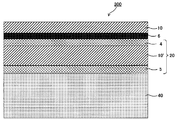
- One embodiment of the present disclosure provides a laminate having the polyimide film of one embodiment of the present disclosure and a hard coat layer containing a radically polymerizable compound and at least one polymer of a cationically polymerizable compound. .
- An embodiment of the present disclosure provides a surface material for a display, which is the polyimide film of the embodiment of the present disclosure or the laminate of the embodiment of the present disclosure.
- one embodiment of the present disclosure is the polyimide film of the one embodiment of the present disclosure or the laminate of the one embodiment of the present disclosure;
- a transparent electrode composed of a plurality of conductive parts disposed on one side of the polyimide film or the laminate;
- a touch panel member is provided having a plurality of lead lines electrically connected on at least one side of an end of the conductive portion.
- one embodiment of the present disclosure is the polyimide film of the one embodiment of the present disclosure or the laminate of the one embodiment of the present disclosure;
- a liquid crystal display device comprising: a liquid crystal display unit having a liquid crystal layer between opposing substrates disposed on one side of the polyimide film or the laminate.
- one embodiment of the present disclosure is the polyimide film of the one embodiment of the present disclosure or the laminate of the one embodiment of the present disclosure;
- An organic electroluminescent display device comprising: an organic electroluminescent display unit having an organic electroluminescent layer between opposing substrates, disposed on one side of the polyimide film or the laminate.
- a resin film having good transparency and durability and reduced optical distortion can be provided.
- a laminate having the resin film, a surface material for a display which is the resin film or the laminate, a touch panel member including the resin film or the laminate, a liquid crystal display device, And an organic electroluminescent display can be provided.
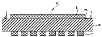
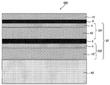
- FIG. 5 is a cross-sectional view of the touch panel member shown in FIG. 2 and FIG.
- FIG. 5 is a cross-sectional view of the touch panel member shown in FIG. 2 and FIG.
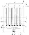
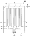
- FIG. 5 is a schematic plan view showing an example of a conductive member provided with a layered product of this indication.
- FIG. 2 is a cross-sectional view of the touch panel member shown in FIG. 2 and FIG.
- FIG. 5 is a schematic plan view showing an example of a conductive member provided with a layered product of this indication.
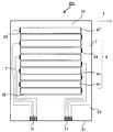
- It is a schematic sectional drawing which shows another example of the touch-panel member of this indication.
- the polyimide film of one embodiment of the present disclosure has a temperature-loss tangent (tan ⁇ ) curve obtained by dynamic viscoelasticity measurement.
- the maximum value of tan ⁇ in the following temperature range is 0.18 or more,
- the total light transmittance measured in accordance with JIS K7361-1 is 85% or more.
- tan ⁇ in the temperature-loss tangent (tan ⁇ ) curve obtained by dynamic viscoelasticity measurement, tan ⁇ in the temperature range of not less than 500 ° C. and not less than the temperature of the high temperature side minimum value of the first peak where the maximum value is maximum.
- the present inventors examined among the resin films paying attention to a polyimide film derived from its chemical structure and known to be excellent in durability.
- a polyimide film has a problem that optical distortion is large, and especially the phase contrast of a film thickness direction is large.
- Retardation occurs due to the anisotropy of the refractive index.
- the anisotropy of the refractive index generally occurs when the polymer chains in the solid are not randomly present but are oriented regularly.
- Polyimides tend to have more linear molecular structures in polymer chains because there are fewer bendable bond sites in the chemical structure as compared to other resins.
- Such a structure is a factor that can increase the elastic modulus, but it also becomes a factor that makes it easy to fold regularly in a state where the linear molecular structure is oriented in the film thickness direction. It is assumed that the phase difference in the film thickness direction is large.
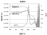
- the present inventors measured the temperature-loss tangent (tan ⁇ ) curve (hereinafter may be simply referred to as the tan ⁇ curve) obtained by measuring the dynamic viscoelasticity of a polyimide film, and the temperature of the high temperature side minimum value of the first peak. When the maximum value of tan ⁇ in the temperature range of 500 ° C.
- the tan ⁇ is a value obtained by dividing the loss elastic modulus by the storage elastic modulus, and indicates the viscoelastic property of the polymer material.
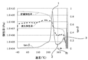
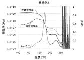
- FIG. 1 shows an example of a tan ⁇ curve, a storage elastic modulus curve, and a loss elastic modulus curve of the polyimide film of the present disclosure.
- the temperature of the maximum value of the first peak (1) at which the maximum value of the tan ⁇ curve is the maximum indicates the glass transition point of the polyimide film.
- the present inventors can obtain a sufficiently reduced retardation with a polyimide film in which the maximum value of tan ⁇ in the first peak high temperature region is 0.18 or more. I found that.
- Temperature-loss tangent (tan ⁇ ) curve The polyimide film of the present disclosure has a temperature-loss tangent (tan ⁇ ) curve obtained by dynamic viscoelasticity measurement.
- the maximum value of tan ⁇ in a temperature range of 0 ° C. or less is 0.18 or more.
- the maximum value of tan ⁇ may be 0.18 or more in the temperature range of not less than the temperature of the high temperature side minimum value of the first peak having the maximum value at the maximum in the tan ⁇ curve and 460 ° C. or less.
- the tan ⁇ curve of the polyimide film of the present disclosure has a first peak whose maximum value is the largest.
- the temperature at the maximum of the first peak indicates the glass transition temperature of the polyimide film.
- the temperature range in which the first peak is present is not particularly limited, but is preferably 400 ° C. or less from the viewpoint of transparency.
- the temperature range in which the first peak is present is preferably 200 ° C. or more, and more preferably 250 ° C. or more.
- the polyimide film of the present disclosure has a temperature range from a temperature (2 t) to 500 ° C. or less at the high temperature side minimum value (2) of the first peak (1) having the maximum value in the tan ⁇ curve.
- the maximum value (3) of tan ⁇ in the above is 0.18 or more.
- the maximum value of tan ⁇ is preferably 0.20 or more, and more preferably 0.21 or more, in order to obtain a further reduced phase difference.
- the upper limit of the maximum value of tan ⁇ is not particularly limited, but is preferably 0.50 or less, and more preferably 0.30 or less.
- the maximum value of tan ⁇ in the temperature range of not less than the temperature of the high temperature side minimum value of the first peak and not more than 500 ° C. is the temperature range of the high temperature side minimum value from the maximum value of the first peak, ie, the decrease of the first peak
- the value of tan ⁇ in the phase is not included.
- the temperature range above the temperature of the high temperature side minimum value of the first peak is 200 ° C. or more and 450 ° C. or less from the relationship with the preferable temperature range in which the first peak exists, ie, the transparency and heat resistance of the polyimide film. Is preferably 250 ° C. or more and 450 ° C. or less, more preferably 300 ° C. or more and 450 ° C.
- the maximum value of the peak may be 0.18 or more; The maximum value of is more preferably 0.20 or more, and still more preferably 0.21 or more.
- the said peak which exists in the temperature range of 500 degreeC or less above the temperature of the high temperature side minimum value of the said 1st peak reduces a phase difference that a maximum value is the 2nd largest 2nd peak in a tan-delta curve.
- the tan ⁇ curve has a first peak having a maximum maximum value, and the second maximum value is 0.18 or more in a temperature range higher than the temperature of the maximum value of the first peak. Having a peak is preferable in terms of reducing the phase difference. Furthermore, the tan ⁇ curve has a second peak with the second largest maximum value in the temperature range of 500 ° C. or less at a temperature higher than the temperature of the high temperature side minimum value of the first peak where the maximum value is the largest.
- the maximum value is preferably 0.18 or more, more preferably 0.20 or more, and still more preferably 0.21 or more.
- the dynamic viscoelasticity measurement is performed as a deformation mode with a measurement range of -40 ° C or more and 500 ° C or less by a dynamic viscoelasticity measurement device RSA-G2 (manufactured by TA Instruments) in a measurement room at 23 ° C and 56% RH.
- the tensile force can be selected, under a nitrogen atmosphere, at a frequency of 1 Hz, a heating rate of 10 ° C./min, a minimum load of 2 g, Axial force> Dynamic Force 1.5%, and Strain 0.1%.
- a test piece prepares length 40 mm, width 5 mm, and can measure the distance between chucks as 20 mm.
- the data is quantified and analyzed from the numerical value.
- the peak of the tan ⁇ curve refers to a peak having an inflection point which is a maximum value and having a peak width of 3 ° C. or more between valleys of the peak and noise etc.
- the fine vertical fluctuation derived from is not interpreted as the above-mentioned peak.
- the polyimide film of the present disclosure has a total light transmittance of 85% or more as measured in accordance with the aforementioned JIS K7361-1. Such high transmittance allows for good transparency and can be a glass substitute material.
- the total light transmittance of the polyimide film of the present disclosure measured according to JIS K7361-1 is preferably 88% or more, more preferably 89% or more, and particularly preferably 90% or more. Is preferred.
- the polyimide film of the present disclosure preferably has a total light transmittance of 85% or more, more preferably 88% or more, measured in accordance with JIS K7361-1 at a thickness of 5 ⁇ m to 100 ⁇ m.
- the polyimide film of the present disclosure preferably has a total light transmittance of 85% or more, more preferably 88% or more, measured at a thickness of 50 ⁇ m ⁇ 5 ⁇ m in accordance with JIS K7361-1. It is more preferably 89% or more, and particularly preferably 90% or more.
- the total light transmittance measured according to JIS K7361-1 can be measured, for example, by a haze meter (for example, HM150 manufactured by Murakami Color Research Laboratory). From the measured value of the total light transmittance of a certain thickness, the converted total light transmittance of different thicknesses can be determined according to the Lambert-Beer's law, which can be used.
- a polyimide is obtained by reacting a tetracarboxylic acid component and a diamine component. After the polyamic acid which is a precursor is obtained by polymerizing a tetracarboxylic acid component and a diamine component, the precursor is imidized. Accordingly, the polyimide used in the present disclosure is one containing a tetracarboxylic acid residue and a diamine residue in the main chain.
- tetracarboxylic acid residue refers to a residue obtained by removing four carboxyl groups from tetracarboxylic acid, and represents the same structure as a residue obtained by removing an acid dianhydride structure from tetracarboxylic acid dianhydride.
- a diamine residue means the residue remove
- the production of the polyimide film may be carried out by a thermal imidization method in which it is molded in the state of a polyimide precursor and then heat treated to form polyimide. It may be carried out by removing the solvent from the solution which has become polyimide (for example, made into polyimide by chemical imidization), or it can also be carried out by a method using the thermal imidization and the chemical imidization in combination. However, among them, it is preferable to manufacture the polyimide film of the present disclosure by a method of forming a polyimide film by heating (thermal imidization) after film formation using a polyimide precursor solution, from the viewpoint of easily reducing retardation.
- polyimide precursors have higher backbone flexibility than polyimides and are more likely to be present irregularly in the film.
- imidation in such a solid phase from the polyimide precursor which exists in such an irregular state even after being made into a polyimide, it is easy to take an irregular structure.
- the phase difference tends to be lower in the method of producing a polyimide film by heating after film formation of the polyimide precursor.
- the polyimide obtained by imidizing a polyimide precursor (polyamic acid) in a solution by chemical imidization has a linear molecular structure due to the reduction of bendable movable parts of the molecular structure during film formation. Cheap.
- the polyimide in the obtained polyimide film is easily folded regularly in a state in which it is oriented in a direction parallel to the film thickness, the intermolecular interaction becomes large and the retardation easily becomes large.
- a method such as polyimide having a flexible skeleton or instantaneously removing the solvent. From such reasons, it is preferable to use thermal imidization in order to make the maximum value of tan ⁇ in the first peak high temperature region within the range of 0.18 or more in the tan ⁇ curve.
- tetracarboxylic acid component to be a tetracarboxylic acid residue
- a tetracarboxylic acid component having an aromatic ring is preferable in terms of improving the surface hardness of the polyimide film.
- tetracarboxylic acid dianhydride having an aromatic ring for example, pyromellitic acid dianhydride, 3,3 ′, 4,4′-benzophenonetetracarboxylic acid dianhydride 2,2 ', 3,3'-benzophenonetetracarboxylic dianhydride, 3,3', 4,4'-biphenyltetracarboxylic dianhydride, 2,2 ', 3,3'-biphenyltetracarboxylic acid Acid dianhydride, 2,2-bis (3,4-dicarboxyphenyl) propane dianhydride, 2,2-bis (2,3-dicarboxyphenyl) propane dianhydride, bis (3,4-di Carboxyphenyl) ether dianhydride, bis (3,4-dicarboxyphenyl) sulfone dianhydride, 1,1-bis (2,3-dicarboxypheny
- the tetracarboxylic acid component which has an aliphatic ring is also preferable from the point of the light transmittance of a polyimide film.
- tetracarboxylic acid dianhydrides having an aliphatic ring include cyclohexanetetracarboxylic acid dianhydride, cyclopentanetetracarboxylic acid dianhydride, dicyclohexane-3,4,3 ′, 4′-tetracarboxylic acid Anhydride, cyclobutane tetracarboxylic acid dianhydride, etc. are mentioned.
- the tetracarboxylic acid component mentioned above can also be used individually or in mixture of 2 or more types.
- the diamine which has an aromatic ring for example is preferable from the point of durability of a polyimide film, and surface hardness.
- the diamine which has an aliphatic ring is also preferable from the point of the light transmittance of a polyimide film.
- the polyimide film which concerns on this indication contains the polyimide which contains the diamine residue which has a silicon atom in a principal chain especially.
- the silicon atom portion can be in a bent structure, so it is easy to obtain a polyimide having a polymer chain containing a more bent molecular structure. It is preferable from the point which is easy to obtain.
- diamine having an aromatic ring for example, 4,4′-diaminodiphenyl sulfone, 3,4′-diaminodiphenyl sulfone, 2,2-bis (4-aminophenyl) propane, 2,2-bis (4-bis (4-aminophenyl) propane) Aminophenyl) hexafluoropropane, p-phenylenediamine, o-phenylenediamine, 3,4'-diaminodiphenyl ether, 4,4'-diaminodiphenyl ether, 3,4'-diaminodiphenyl sulfide, 4,4'-diaminodiphenyl sulfide 4,4'-Diaminobenzophenone, 3,4'-diaminobenzophenone, 4,4'-diaminobenzanilide, 4,4'-diaminodiphenylmethane, 3,4'-diamino
- diamine having an aliphatic ring examples include trans-cyclohexanediamine, trans-1,4-bismethylenecyclohexanediamine, 2,6-bis (aminomethyl) bicyclo [2,2,1] heptane, 2,5- Bis (aminomethyl) bicyclo [2,2,1] heptane and the like can be mentioned.
- diamine which has a silicon atom in a principal chain
- diamine represented by the following general formula (A) is mentioned, for example.
- each L independently represents a direct bond or an -O- bond
- each R 10 independently represents a substituent, and may contain an oxygen atom or a nitrogen atom
- R 11 independently represents a monovalent hydrocarbon group having 1 to 20 carbon atoms which may be substituted, and R 11 may independently have a substituent, and may contain an oxygen atom or a nitrogen atom
- k is a number of 0 to 200.
- a plurality of L, R 10 and R 11 may be the same or different from each other)
- the alkyl group may be linear, branched or cyclic, and may be linear or a combination of branched and cyclic.
- the alkyl group having 1 to 20 carbon atoms is preferably an alkyl group having 1 to 10 carbon atoms, and specifically, a methyl group, an ethyl group, a propyl group, an isopropyl group, a butyl group, an isobutyl group, Examples thereof include t-butyl group, pentyl group and hexyl group.
- the cyclic alkyl group is preferably a cycloalkyl group having 3 to 10 carbon atoms, and specific examples thereof include a cyclopentyl group and a cyclohexyl group.
- the aryl group is preferably an aryl group having 6 to 12 carbon atoms, and specific examples thereof include a phenyl group, a tolyl group and a naphthyl group.
- the monovalent hydrocarbon group represented by R 10 may be an aralkyl group, and examples thereof include a benzyl group, a phenylethyl group and a phenylpropyl group.
- hydrocarbon group which may contain an oxygen atom or a nitrogen atom
- examples of the hydrocarbon group which may contain an oxygen atom or a nitrogen atom include, for example, an ether bond, a carbonyl bond, an ester bond, an amide bond, and an imino bond between a divalent hydrocarbon group described later and the monovalent hydrocarbon group. Included is a group bonded via at least one of the bonds (—NH—).
- the substituent which the monovalent hydrocarbon group represented by R 10 may have is not particularly limited as long as the effects of the present disclosure are not impaired, and for example, a halogen atom such as a fluorine atom or a chlorine atom And hydroxyl groups.
- the monovalent hydrocarbon group represented by R 10 is an alkyl group having 1 to 3 carbon atoms or an aryl group having 6 to 10 carbon atoms from the viewpoint of improving bending resistance and compatibility with surface hardness. Is preferred.
- the alkyl group having 1 to 3 carbon atoms is more preferably a methyl group, and the aryl group having 6 to 10 carbon atoms is more preferably a phenyl group.
- the alkylene group may be linear, branched or cyclic, and may be linear or a combination of branched and cyclic.
- the alkylene group having 1 or more and 20 or less carbon atoms is preferably an alkylene group having 1 or more and 10 or less carbon atoms, and for example, a straight chain such as methylene group, ethylene group, various propylene groups, various butylene groups and cyclohexylene groups Examples include groups in combination of linear or branched alkylene groups and cyclic alkylene groups.
- the arylene group is preferably an arylene group having a carbon number of 6 to 12, and examples of the arylene group include a phenylene group, a biphenylene group, and a naphthylene group, and further have a substituent for the aromatic ring described later.
- the divalent hydrocarbon group which may contain an oxygen atom or a nitrogen atom include an ether bond, a carbonyl bond, an ester bond, an amide bond, and an imino bond (-NH-) between the above-mentioned divalent hydrocarbon groups. At least one bonded group is mentioned.
- the substituent which the divalent hydrocarbon group represented by R 11 may have is the same as the substituent which the monovalent hydrocarbon group represented by R 10 may have. It is good.
- the divalent hydrocarbon group represented by R 11 is an alkylene group having 1 to 6 carbon atoms, or an arylene group having 6 to 10 carbon atoms, from the viewpoint of improving bending resistance and compatibility with surface hardness. It is more preferable that it is an alkylene group having 2 to 4 carbon atoms.
- a diamine residue having a silicon atom in the main chain is a diamine residue having one or two silicon atoms in the main chain, from the viewpoint of achieving low retardation and improving the compatibility of bending resistance and surface hardness. It is preferably a group.
- the number of silicon atoms in the main chain of the diamine residue is not particularly limited, but is preferably one or two, and more preferably two. When the number of silicon atoms is 3 or more, the effect for realizing low retardation is saturated, and the flexibility of the polyimide is too high, which may affect the heat resistance.
- diamines having one silicon atom in the main chain examples include diamines represented by the following general formula (A-1). Further, examples of the diamine having two silicon atoms in the main chain include diamines represented by the following general formula (A-2).
- L is each independently a direct bond or -O- bond, and each R 10 independently has a substituent Or a monovalent hydrocarbon group having 1 to 20 carbon atoms which may contain an oxygen atom or a nitrogen atom, and each R 11 may independently have a substituent, and an oxygen atom Or a divalent hydrocarbon group having 1 to 20 carbon atoms which may contain a nitrogen atom, and a plurality of L, R 10 and R 11 may be identical to or different from each other)
- the molecular weight of the diamine residue having a silicon atom in the main chain is preferably 1,000 or less, more preferably 800 or less, and still more preferably 500 or less. Preferably, it is 300 or less.
- the molecular weight of the diamine residue is calculated by subtracting the molecular weight (32) of two amino groups (-NH 2 ) from the molecular weight of the diamine.
- the diamine residue which has a silicon atom in a principal chain can also be used individually or in mixture of 2 or more types.
- the diamine having one or two silicon atoms in the main chain is a diamine having two silicon atoms from the viewpoint of light transmittance of the resulting polyimide, and in terms of bending resistance and surface hardness, Furthermore, 1,3-bis (3-aminopropyl) tetramethyldisiloxane, 1,3-bis (4-aminobutyl) tetramethyldisiloxane, 1,3-bis (5-aminopentyl) tetramethyldisiloxane, etc. However, it is preferable from the viewpoints of the availability of these compounds and the light transmittance and surface hardness of the resulting polyimide.
- the ratio of the diamine having a silicon atom in the main chain to the total amount of diamine is not particularly limited, but from the viewpoint of reducing the retardation of the obtained polyimide film, 1 It is preferable that it is mol% or more, It is more preferable that it is 2.5 mol% or more, It is still more preferable that it is 5 mol% or more. Also, from the viewpoint of the heat resistance of the polyimide film to be obtained, it is preferably 50 mol% or less, more preferably 45 mol% or less, more preferably 40 mol% or less, and 20 mol% or less. Even more preferred is
- the total amount of the tetracarboxylic acid component and the diamine component is 100 mol%
- the total of the tetracarboxylic acid having an aromatic ring and the diamine having an aromatic ring is It is preferably 50 mol% or more, more preferably 60 mol% or more, and still more preferably 75 mol% or more.
- the polyimide may contain an aromatic ring, and (i) a fluorine atom, (ii) an aliphatic ring, and (iii) an aromatic ring may be substituted with a sulfonyl group or fluorine. It is preferable from the viewpoint of light transmittance and surface hardness that it contains at least one selected from the group consisting of an alkylene group-linked structure, and further, in addition to these structures, a diamine residue having a silicon atom in the main chain It is preferable to include a group from the viewpoint of low retardation and flex resistance.
- the polyimide when the polyimide contains at least one selected from a tetracarboxylic acid residue having an aromatic ring and a diamine residue having an aromatic ring, the molecular skeleton becomes rigid and the durability is enhanced, and the surface hardness is improved.
- the rigid aromatic ring skeleton tends to extend the absorption wavelength to a long wavelength, and the transmittance in the visible light range tends to decrease.
- the polyimide contains (i) a fluorine atom, the light transmission is improved because the charge transfer of the electronic state in the polyimide skeleton can be made difficult.
- the light transmission is improved from the point of being able to inhibit the movement of charges in the skeleton by breaking the conjugation of ⁇ electrons in the polyimide skeleton.
- the polyimide has a structure in which (iii) aromatic rings are linked by an alkylene group which may be substituted with a sulfonyl group or a fluorine group, the charge transfer in the skeleton is broken by breaking the conjugation of ⁇ electrons in the polyimide skeleton. The light transmission is improved because it can be inhibited.
- a polyimide containing a fluorine atom is preferably used from the viewpoint of improving the light transmittance and the surface hardness.
- the content ratio of fluorine atoms is preferably such that the ratio (F / C) of the number of fluorine atoms (F) to the number of carbon atoms (C) when the polyimide surface is measured by X-ray photoelectron spectroscopy is 0.01 or more Furthermore, it is preferable that it is 0.05 or more.
- the ratio (F / C) of the number of fluorine atoms (F) to the number of carbon atoms (C) is 1 or less Is preferably, and further preferably 0.8 or less.
- the above ratio by the measurement of X-ray photoelectron spectroscopy (XPS) can be determined from the value of atomic% of each atom measured using an X-ray photoelectron spectrometer (for example, Theta Probe, manufactured by Thermo Scientific) .
- a tetracarboxylic acid and a diamine not having a silicon atom contains an aromatic ring and a fluorine atom. Furthermore, it is preferred that both the tetracarboxylic acid and the diamine not having a silicon atom contain an aromatic ring and a fluorine atom.
- a tetracarboxylic acid having an aromatic ring and a fluorine atom when the total amount of the tetracarboxylic acid component and the diamine component is 100 mol%, from the viewpoint of surface hardness and light transmittance of the obtained polyimide and the point of bending resistance.
- the total amount of the diamine having an aromatic ring and a fluorine atom is preferably 50 mol% or more, more preferably 60 mol% or more, and still more preferably 75 mol% or more.
- the light transmittance of the resulting polyimide is improved in that at least 50% of the hydrogen atoms bonded to carbon atoms contained in the tetracarboxylic acid component and the diamine component are hydrogen atoms directly bonded to the aromatic ring. And from the viewpoint of improving surface hardness and bending resistance.
- the percentage of hydrogen atoms (number) directly bonded to the aromatic ring in all hydrogen atoms (number) bonded to carbon atoms is preferably 60% or more, more preferably 70% or more .
- the ratio of hydrogen atoms (number) directly bonded to the aromatic ring in all hydrogen atoms (number) in carbon atoms contained in the polyimide is high-performance liquid chromatography, gas chromatography mass of polyimide decomposition product It can be determined using an analyzer and NMR.
- the sample is decomposed by an aqueous alkaline solution or supercritical methanol, and the resulting decomposition product is separated by high performance liquid chromatography, and the qualitative analysis of each separated peak is performed by gas chromatography mass spectrometry, NMR, etc.
- the ratio of hydrogen atoms (number) directly bonded to the aromatic ring in all hydrogen atoms (number) in the polyimide can be determined by performing measurement using high performance liquid chromatography.
- the polyimide film which concerns on this indication contains the polyimide which has a structure represented by following General formula (1) from the point of light transmittance, heat resistance, and rigidity.
- R 1 represents a tetravalent group which is a tetracarboxylic acid residue having an aromatic ring or an aliphatic ring
- R 2 represents a divalent group which is the diamine residue.
- n represents the number of repeating units
- tetracarboxylic dianhydride having an aromatic ring in R 1 and the tetracarboxylic dianhydride having an aliphatic ring those similar to the above can be used. These may be used alone or in combination of two or more.
- R 1 in the general formula (1) is a residue of cyclohexanetetracarboxylic acid dianhydride, cyclopentanetetracarboxylic acid, from the viewpoint of light transmittance in the polyimide to be obtained, and bending resistance and surface hardness.
- Anhydride residue Dicyclohexane-3,4,3 ′, 4′-tetracarboxylic acid dianhydride residue, cyclobutanetetracarboxylic acid dianhydride residue, pyromellitic acid dianhydride residue, 3,3 ′ 1,4,4'-biphenyltetracarboxylic acid dianhydride residue, 2,2 ', 3,3'-biphenyltetracarboxylic acid dianhydride residue, 4,4'-(hexafluoroisopropylidene) diphthalic anhydride Residue, 3,4 '-(hexafluoroisopropylidene) diphthalic anhydride residue, 3,3'-(hexafluoroisopropylidene) diphthalic anhydride residue, 4,4'-oxydiphthalic acid Anhydride residue, and is preferably at least one tetravalent group selected from the group consisting of 3,4'-oxydiphthalic anhydride residue.
- the tetracarboxylic acid component is particularly preferably 4,4 '-(hexafluoroisopropylidene) diphthalic anhydride, 3,4'-(hexafluoroisopropylidene) diphthalic anhydride, and 3,3 from the viewpoint of good light transmittance. More preferably, it is at least one selected from the group consisting of '-(hexafluoroisopropylidene) diphthalic anhydride, 4,4'-oxydiphthalic anhydride, and 3,4'-oxydiphthalic anhydride.
- Tetracarboxylic acid group (group A) suitable for improving the rigidity of the resulting polyimide such as at least one member selected from the group consisting of: cyclohexane tetracarboxylic acid dianhydride, cyclopentane tetracarbon Acid dianhydride, dicyclohexane-3,4,3 ′, 4′-tetracarboxylic acid dianhydride, cyclobutanetetracarboxylic acid dianhydride, 4,4 ′-(hexafluoroisopropylidene) diphthalic acid anhydride, 3 4,4 '-(hexafluoroisopropylidene) diphthalic
- the content ratio of the tetracarboxylic acid group (group A) suitable for improving the rigidity and the tetracarboxylic acid group (group B) suitable for improving the light transmittance is the light transmittance.
- At least one of 4,4 '-(hexafluoroisopropylidene) diphthalic anhydride and 3,4'-(hexafluoroisopropylidene) diphthalic anhydride containing a fluorine atom is used as the group B. It is preferable from the point of the improvement of the light transmittance in the polyimide obtained.
- R 2 represents a divalent group which is a diamine residue, and is not particularly limited as long as it contains a diamine residue having an aromatic ring or an aliphatic ring.
- a bivalent diamine residue the thing similar to the above can be used. These may be used alone or in combination of two or more.
- diamine residue having an aromatic ring or an aliphatic ring contained in R 2 may each, using the same as those described above. These may be used alone or in combination of two or more.
- the diamine residue having an aromatic ring or an aliphatic ring in R 2 in the general formula (1) is trans-, from the viewpoint of light transmittance, bending resistance, surface hardness and low hygroscopicity.
- R 3 and R 4 each independently represent a hydrogen atom, an alkyl group or a perfluoroalkyl group.
- diamine residue having a silicon atom in the main chain is included as R 2. Since the diamine residue which has a silicon atom in the principal chain which can be preferably used as R 2 is as described above, the description is omitted here.
- R 2 in the general formula (1) When containing a diamine residue having a silicon atom in the main chain as R 2 in the general formula (1), in R 2 in the general formula (1), 2.5 mol% to 50 mol of the total amount of R 2 % Or less is a diamine residue having a silicon atom in the main chain, and 50 to 97.5 mol% of the total amount of R 2 has no silicon atom and has an aromatic ring or an aliphatic ring By being a diamine residue, retardation is reduced and surface hardness sufficient as a protective film can be obtained, which is preferable.
- R 2 in the general formula (1) is preferably a diamine residue having a silicon atom in the main chain is 3.5 mol% or more of the total amount of R 2 , and more preferably 5 It is preferable that it is mol% or more.
- R 2 in the general formula (1) from the point where the phase difference is reduced, the diamine residue having a silicon atom in the main chain, 10 mol% or more of the total amount of R 2, even more than 20 mol% good.
- R 2 in the general formula (1) is that the diamine residue having a silicon atom in the main chain is 45 mol% or less of the total amount of R 2 from the viewpoint of improving surface hardness and light transmittance.
- it is more preferably 40 mol% or less.
- the other diamine residue is preferably 10 mol% or less, more preferably 5 mol% or less, still more preferably 3 mol% or less, and particularly preferably 1 mol% or less of the total amount of R 2 It is preferable that it is the following.
- the diamine residue etc. which do not have a silicon atom and do not have an aromatic ring or an aliphatic ring are mentioned, for example.
- a diamine residue having a silicon atom in the main chain of the total amount of R 2 (100 mol%), silicon atoms in the main chain
- the remaining (100% -x%) of the remaining (100% -x%) of the mole% (x mole%) of the diamine residue having 50 has no silicon atom and has an aromatic ring or an aliphatic ring It is preferable that it is a diamine residue.
- R 2 in the general formula (1) is a diamine residue having no silicon atom, and silicon in the main chain, from the viewpoint of reducing retardation and achieving a balance between bending resistance and surface hardness.
- 50 mole% 2.5 mol% or more of the total amount of R 2 or less is a main one silicon atom in a chain or two with diamine residue, of the total amount of R 2 (100 mol%), the 50 mol% or more and 97.5 mol% or less, which is the remainder (100% -x%) of the mol% (x mol%) of the diamine residue having one or two silicon atoms in the main chain has a silicon atom
- it is a diamine residue having an aromatic ring or an aliphatic ring.
- R 2 in the general formula (1) has 3 or less of the total amount of R 2 diamine residues having one or two silicon atoms in the main chain.
- the diamine residue having no silicon atom and having an aromatic ring or an aliphatic ring corresponds to the above, R 2 It is preferable that it is 97 mol% or less of the total of, and still more preferable that it is 95 mol% or less.
- R 2 in the general formula (1) from the point where the phase difference is reduced, diamine residue having one or two silicon atoms in the main chain, at least 10 mole% of the total amount of R 2, further 20 mol%
- the diamine residue having no silicon atom and having an aromatic ring or an aliphatic ring is 90 mol% or less, and further 80 mol or less of the total amount of R 2 corresponding to the above. It may be less than%.
- R 2 in the general formula (1) has a diamine residue having one or two silicon atoms in the main chain from the viewpoint of improving surface hardness and light transmittance while reducing retardation.
- Te is preferably at least 55 mol% of the total amount of R 2, is preferably more further 60 mol% or more.
- n represents the number of repeating units and is 1 or more.
- the number n of repeating units in the polyimide may be appropriately selected, and is not particularly limited.
- the average number of repeating units is usually 10 to 2,000, preferably 15 to 1,000.
- R 1 in each repeating unit may be the same or different, and R 2 in each repeating unit may be the same or different.
- the polyimide having a structure represented by the general formula (1) preferably has a number average molecular weight of 10000 or more, more preferably 20000 or more, from the viewpoint of strength and bending resistance when formed into a film. Preferably, it is more preferably 30000 or more, and particularly preferably 50000 or more.
- the upper limit is not particularly limited, but is preferably 10,000,000 or less, more preferably 500,000 or less, from the viewpoint of easy synthesis and easy availability.
- the number average molecular weight of the polyimide can be measured in the same manner as the number average molecular weight of the polyimide precursor described later.
- the polyimide having the structure represented by the general formula (1) preferably has a weight average molecular weight of 20000 or more, and 30000 or more, from the viewpoint of strength and bending resistance when formed into a film. More preferably, it is 40000 or more, still more preferably 80000 or more.
- the upper limit is not particularly limited, but is preferably 10,000,000 or less, more preferably 500,000 or less, from the viewpoint of easy synthesis and easy availability.
- the weight average molecular weight of the polyimide can be measured by gel permeation chromatography (GPC).
- polyimide is used as an N-methyl pyrrolidone (NMP) solution with a concentration of 0.1% by weight, and a developing solvent is a 30 mmol% LiBr-NMP solution with a water content of 500 ppm or less.
- NMP N-methyl pyrrolidone
- a developing solvent is a 30 mmol% LiBr-NMP solution with a water content of 500 ppm or less.
- the weight average molecular weight is determined based on a polystyrene standard sample at the same concentration as the sample.
- the polyimide used in the present disclosure may have a structure different from the polyimide in a part thereof, such as a polyamide structure, as long as the effects of the present disclosure are not impaired.
- the polyimide used for this indication may have a structure different from the structure represented by the said General formula (1) in the one, unless the effect of this indication is impaired.
- the structure represented by the general formula (1) is preferably 95% or more, more preferably 98% or more, and more preferably 100% of the total number of repeating units of the polyimide. Even more preferred is As a structure different from the structure represented by the said General formula (1), the case where the tetracarboxylic-acid residue etc.
- polyamide structure which do not have an aromatic ring or an aliphatic ring etc. are contained, for example, and a polyamide structure are mentioned.
- the polyamide structure which may be contained include a polyamideimide structure containing a tricarboxylic acid residue such as trimellitic anhydride, and a polyamide structure containing a dicarboxylic acid residue such as terephthalic acid.
- the content ratio of each repeating unit in the polyimide, and the content ratio (mol%) of each tetracarboxylic acid residue and each diamine residue can be determined from the molecular weight of the feed at the time of polyimide production.
- the content ratio (mol%) of each tetracarboxylic acid residue and each diamine residue in the polyimide is the decomposition product of the polyimide obtained by decomposition with an alkaline aqueous solution or supercritical methanol as described above.
- the polyimide film of the present disclosure may further contain an additive, if necessary, in addition to the polyimide.
- the additive include inorganic particles, a silica filler for facilitating winding, and a surfactant for improving film forming properties and defoaming properties.
- the phase difference is reduced. Since the measured value of the retardation is affected by the film thickness, it may not be possible to evaluate the superiority or inferiority of the retardation of the polyimide film only by the measured value. Therefore, it is usually calculated by dividing the retardation by the film thickness. Convert to refractive index and evaluate.
- the birefringence in the film thickness direction at a wavelength of 590 nm is preferably smaller, and more preferably less than 0.008, and still more preferably 0.005 or less. It is even more preferable that it is 004 or less.
- the retardation in the film thickness direction at a wavelength of 590 nm and the birefringence of the polyimide film of the present disclosure can be determined as follows. First, a retardation value (Rth) in the film thickness direction of a polyimide film is measured with light at a wavelength of 590 nm at 25 ° C. using a retardation measurement apparatus (for example, product name “KOBRA-WR” manufactured by Oji Scientific Instruments Co., Ltd.) taking measurement.
- a retardation measurement apparatus for example, product name “KOBRA-WR” manufactured by Oji Scientific Instruments Co., Ltd.
- the film thickness direction retardation value (Rth) measures a retardation value at 0 degree incidence and a retardation value at 40 degree oblique incidence, and calculates a film thickness direction retardation value Rth from these retardation values.
- the retardation value of the oblique 40-degree incidence is measured by causing light of wavelength 590 nm to be incident on the retardation film from a direction inclined 40 degrees from the normal of the retardation film.
- the birefringence in the film thickness direction of the polyimide film can be determined by substituting it into the formula: Rth / d. Said d represents the film thickness (nm) of a polyimide film.
- the refractive index of the slow axis direction in the in-plane direction of the film (the direction in which the refractive index in the film in-plane direction is maximum) is nx
- the polyimide film of the present disclosure preferably has a yellowness (YI value) of 30 or less calculated in accordance with JIS K7373-2006.
- the yellowness (YI value) calculated in accordance with JIS K7373-2006 is preferably 20 or less, more preferably 15 or less, and still more preferably 10 or less.
- the polyimide film of the present disclosure preferably has a yellowness (YI value) calculated according to JIS K7373-2006 at a thickness of 5 ⁇ m to 100 ⁇ m, preferably 30 or less, and more preferably 20 or less.
- the polyimide film of the present disclosure preferably has a yellowness (YI value) of 10 or less, preferably 7 or less, at a thickness of 50 ⁇ m ⁇ 5 ⁇ m, which is calculated according to the aforementioned JIS K7373-2006. Preferably, it is 5 or less.
- the degree of yellowness (YI value) can be determined by the spectrophotometric method using an ultraviolet visible near infrared spectrophotometer (for example, JASCO Corporation V-7100) in accordance with JIS K7373-2006.
- tristimulus values X, Y, Z in the XYZ color system are determined based on the transmittance measured at 1 nm intervals in the range of 250 nm or more and 800 nm or less using a 2 ° field of view, and the X, Y, Z It can be calculated from the value of Z according to the following equation.
- the degree of yellowness of a different thickness is the total of the respective transmittances at each wavelength measured at 1 nm intervals between 250 nm and 800 nm or less of the sample of a specific thickness Similar to the light transmittance, a converted value of each transmittance at each wavelength of different thickness can be obtained according to the Lambert-Beer's law, and it can be calculated and used based on it.
- the haze value of the polyimide film of the present disclosure is preferably 2.0 or less, more preferably 1.5 or less, and still more preferably 1.0 or less from the viewpoint of light transmittance.
- the haze value can preferably be achieved when the thickness of the polyimide film is 5 ⁇ m or more and 100 ⁇ m or less.
- the haze value can be measured by a method according to JIS K-7105, and can be measured, for example, by a haze meter HM150 manufactured by Murakami Color Research Laboratory.
- the polyimide film of the present disclosure measures 15 mm ⁇ 40 mm test pieces in accordance with JIS K7127, and the tensile modulus at 25 ° C. measured at a tensile speed of 8 mm / min and a distance between chucks of 20 mm is the surface hardness. It is preferably 1.8 GPa or more, and may be 5.0 GPa or less from the viewpoint of bending resistance. From the viewpoint of bending resistance and surface hardness, it is more preferable that the energy density be 2.0 GPa or more and 4.0 GPa or less, and still more preferable that the energy density be 2.0 GPa or more and 3.5 GPa or less.
- the tensile modulus is measured at 25 ° C.
- the polyimide film at the time of obtaining the tensile elastic modulus preferably has a thickness of 55 ⁇ m ⁇ 5 ⁇ m.
- the pencil hardness may be 6 B or more, but it is more preferably B or more, and even more preferably HB or more from the viewpoint of surface hardness.
- the pencil hardness of the polyimide film is adjusted according to JIS K 5600-5-4 using a test pencil specified in JIS-S-6006 after conditioning the measurement sample under the conditions of temperature 25 ° C. and relative humidity 60% for 2 hours. It can carry out by performing the pencil hardness test (0. 98N load) prescribed in (1999) on the film surface and evaluating the highest pencil hardness which does not get damaged.
- a tester for example, a pencil scratching film hardness tester manufactured by Toyo Seiki Co., Ltd. can be used.
- the thickness of the polyimide film of the present disclosure may be appropriately selected depending on the application, it is preferably 1 ⁇ m or more, more preferably 5 ⁇ m or more, and still more 10 ⁇ m or more from the viewpoint of strength. Is preferred.
- the polyimide film of the present disclosure may be subjected to surface treatment such as saponification treatment, glow discharge treatment, corona discharge treatment, ultraviolet treatment, flame treatment, and the like.
- the method for producing the polyimide film of the present disclosure is not particularly limited as long as it can produce the polyimide film of the present disclosure, but, for example, as described above, heating the polyamic acid which is a polyimide precursor It is preferable that it is the method of imidating by this, and the following 1st manufacturing method is preferable.
- a first production method Preparing a polyimide precursor resin composition containing a polyamic acid which is a polyimide precursor and an organic solvent (hereinafter referred to as a polyimide precursor resin composition preparation step); Applying the polyimide precursor resin composition to a support to form a polyimide precursor resin coating film (hereinafter referred to as a polyimide precursor resin coating film forming step); And a step of imidizing the polyimide precursor by heating (hereinafter referred to as a thermal imidization step).
- a step of stretching at least one of the polyimide precursor resin coating film and the post-imidized coating film obtained by imidizing the polyimide precursor resin coating film (hereinafter, stretching It may have a process).
- stretching It may have a process.
- a polyimide precursor resin composition contains a polyimide precursor and an organic solvent, and may contain an additive etc. if needed.
- the polyimide precursor represented by following General formula (1 ') is mentioned, for example.
- the polyimide precursor represented by the general formula (1 ′) is a tetracarboxylic acid component to be a tetracarboxylic acid residue in R 1 of the general formula (1 ′), and R 2 of the general formula (1 ′) Is a polyamic acid obtained by polymerization with a diamine component to be a diamine residue.
- the polyimide precursor represented by the general formula (1 ′) preferably has a number average molecular weight or weight average molecular weight of at least 10000 in terms of strength when formed into a film, and more preferably 20000. It is preferable that it is more than. On the other hand, if the average molecular weight is too large, the viscosity will be high, and there is a possibility that the workability such as filtration may be reduced, so it is preferably 10,000,000 or less, more preferably 500,000 or less.
- the number average molecular weight of the polyimide precursor can be determined by NMR (for example, AVANCE III manufactured by BRUKER). For example, after applying a polyimide precursor solution to a glass plate and drying at 100 ° C.
- the number average molecular weight can be calculated from the peak intensity ratio of hydrogen atoms.
- the weight average molecular weight of the polyimide precursor can be measured by gel permeation chromatography (GPC).
- a polyimide precursor is N-methyl pyrrolidone (NMP) solution with a concentration of 0.5% by weight
- a developing solvent is a Tosoh GPC apparatus (HLC-8120, using a 10 mmol% LiBr-NMP solution with a water content of 500 ppm or less)
- HPC-8120 N-methyl pyrrolidone
- the polyimide precursor solution can be obtained by reacting the above-described tetracarboxylic acid dianhydride and the above-described diamine in a solvent.
- the solvent used for synthesis of the polyimide precursor is not particularly limited as long as it can dissolve the above-described tetracarboxylic acid dianhydride and diamine, and, for example, an aprotic polar solvent or a water-soluble alcohol solvent etc. It can be used.
- N-methyl-2-pyrrolidone N, N-dimethylformamide, N, N-dimethylacetamide, dimethylsulfoxide, hexamethylphosphoramide, 1,3-dimethyl-2-imidazolidinone and the like
- organic solvent containing a nitrogen atom of: ⁇ -butyrolactone or the like it is preferable to use an organic solvent containing a nitrogen atom of: ⁇ -butyrolactone or the like.
- the polyimide precursor solution polyamic acid solution
- the dissolution of inorganic particles is suppressed when the polyimide precursor resin composition contains inorganic particles described later.
- an organic solvent containing a nitrogen atom it is preferable to use an organic solvent containing a nitrogen atom, and it is preferable to use N, N-dimethylacetamide, N-methyl-2-pyrrolidone or a combination thereof.
- an organic solvent is a solvent containing a carbon atom.
- an acid dianhydride may be added to the mixed solution of at least 2 types of diamine, and a polyamic acid may be synthesize
- An amic acid in which a diamine having a silicon atom at the main chain at both ends of the anhydride is reacted is synthesized, into which the remaining diamine is fully or partially introduced, and an acid dianhydride is added to polymerize the polyamic acid. Also good.
- diamines having a silicon atom in the main chain are introduced into the polyamic acid in a linked form via one acid dianhydride. It is preferable to polymerize the polyamic acid by such a method because it is specified to some extent in the positional relationship of the amic acid having a silicon atom in the main chain, and a film with low retardation can be easily obtained while maintaining the surface hardness.
- Y / X should be 0.9 or more and 1.1 or less. Preferably, it is more preferably 0.95 or more and 1.05 or less, still more preferably 0.97 or more and 1.03 or less, and particularly preferably 0.99 or more and 1.01 or less.
- the molecular weight (polymerization degree) of the polyamic acid obtained by setting it as such a range can be adjusted moderately.
- the procedure of the polymerization reaction can be selected appropriately from known methods, and is not particularly limited. Alternatively, the polyimide precursor solution obtained by the synthesis reaction may be used as it is, and if necessary, other components may be mixed, or the solvent of the polyimide precursor solution may be dried and dissolved in another solvent. You may use.
- the viscosity at 25 ° C. of the polyimide precursor solution is preferably 500 cps or more and 200,000 cps or less from the viewpoint of forming a uniform coating film and polyimide film.
- the viscosity of the polyimide precursor solution can be measured at 25 ° C. using a viscometer (eg, TVE-22HT, Toki Sangyo Co., Ltd.).
- the said polyimide precursor resin composition may contain the additive as needed.
- the additive include a silica filler for facilitating winding, a surfactant for improving the film forming property and the defoaming property, and the like, and the same as those described in the above-mentioned polyimide film Can be used.
- the organic solvent used for the polyimide precursor resin composition is not particularly limited as long as the polyimide precursor can be dissolved.
- it contains a nitrogen atom such as N-methyl-2-pyrrolidone, N, N-dimethylformamide, N, N-dimethylacetamide, dimethylsulfoxide, hexamethylphosphoramide, 1,3-dimethyl-2-imidazolidinone and the like
- Organic solvents; ⁇ -butyrolactone etc. can be used, but among them, it is preferable to use an organic solvent containing a nitrogen atom for the reason described above.
- the content of the polyimide precursor in the polyimide precursor resin composition is 50% by mass or more in the solid content of the resin composition from the viewpoint of forming a uniform coating film and a polyimide film having a handleable strength.
- the content is preferably 60% by mass or more, and the upper limit may be appropriately adjusted depending on the ingredients.
- the organic solvent in the polyimide precursor resin composition is preferably 40% by mass or more, and more preferably 50% by mass or more in the resin composition, from the viewpoint of forming a uniform coating film and polyimide film. It is preferably 99% by mass or less.
- the storage stability of a polyimide precursor resin composition becomes favorable that the said polyimide precursor resin composition is 1000 ppm or less from the point which can improve productivity.
- the polyimide precursor resin composition contains a large amount of water, the polyimide precursor may be easily decomposed.
- the water content of the polyimide precursor resin composition can be determined using a Karl-Fisher moisture meter (for example, a trace water content measuring device CA-200 type manufactured by Mitsubishi Chemical Co., Ltd.).
- the viscosity at 25 ° C. of a solid content of 15% by mass at a solid content of the polyimide precursor resin composition is preferably 500 cps or more and 100,000 cps or less from the viewpoint of forming a uniform coating film and polyimide film.
- the viscosity of the polyimide precursor resin composition can be measured as a sample volume of 0.8 mL at 25 ° C. using a viscometer (for example, TVE-22HT, Toki Sangyo Co., Ltd.).
- the surface is smooth and heat resistant as a support to be used.
- the material is not particularly limited as long as it is a material having resistance and solvent resistance.
- an inorganic material such as a glass plate, a metal plate whose surface is mirror-finished, and the like can be mentioned.
- the shape of the support is selected depending on the coating method, and may be, for example, a plate, a drum, a belt, a sheet which can be wound on a roll, or the like.
- the application means is not particularly limited as long as it can be applied with a target film thickness, and for example, known means such as die coater, comma coater, roll coater, gravure coater, curtain coater, spray coater, lip coater can be used .
- the application may be performed by a sheet-fed application apparatus or a roll-to-roll application apparatus.
- the solvent in the coating is dried at a temperature of 150 ° C. or less, preferably 30 ° C. or more and 120 ° C. or less until the coating becomes tack-free.
- the drying temperature of the solvent is set to 150 ° C. or less, imidization of the polyamic acid can be suppressed.
- the drying time may be appropriately adjusted depending on the film thickness of the polyimide precursor resin coating film, the type of solvent, the drying temperature and the like, but it is usually 1 minute to 60 minutes, preferably 2 minutes to 30 minutes. When it exceeds the upper limit value, it is not preferable from the viewpoint of the production efficiency of the polyimide film. On the other hand, if the lower limit value is exceeded, rapid drying of the solvent may affect the appearance and the like of the obtained polyimide film.
- the method for drying the solvent is not particularly limited as long as the solvent can be dried at the above temperature, and it is possible to use, for example, an oven, a drying oven, a hot plate, infrared heating, and the like.
- the atmosphere for drying the solvent is preferably under an inert gas atmosphere.
- the inert gas atmosphere is preferably a nitrogen atmosphere, the oxygen concentration is preferably 100 ppm or less, and more preferably 50 ppm or less. Heat treatment in the atmosphere can cause the film to oxidize, color, and degrade performance.
- the imidization is It is preferred to do.
- fever imidation process may be performed with respect to the polyimide precursor in the said polyimide precursor resin coating film before an extending process, or the said polyimide precursor after an extending process It may be applied to a polyimide precursor in a resin coating film, or to both the polyimide precursor in the polyimide precursor resin coating film before the stretching step and the polyimide precursor present in the film after the stretching step You may go.
- the temperature of the imidization is such that the polymer chain in the resulting polyimide tends to have a bent molecular structure, that is, the polymer chain in the polyimide precursor can easily have a bent molecular structure. It may be appropriately selected in accordance with In general, the temperature rise start temperature is preferably 30 ° C. or more, and more preferably 100 ° C. or more. On the other hand, it is preferable to make temperature rising completion temperature into 250 degreeC or more.
- the temperature rising rate is preferably selected appropriately depending on the film thickness of the polyimide film to be obtained, and when the film thickness of the polyimide film is thick, the temperature rising rate is preferably decreased. From the viewpoint of the production efficiency of the polyimide film, the temperature is preferably 5 ° C./min or more. On the other hand, the upper limit of the temperature rising rate is usually 50 ° C./minute or less, preferably 40 ° C./minute or less, and more preferably 30 ° C./minute or less. It is preferable to use the above-mentioned temperature rising rate from the viewpoint of suppressing the appearance defect of the film and the strength decrease, controlling whitening accompanying the imidization reaction, and improving the light transmittance.
- the temperature rise may be continuous or stepwise, but it is preferable to use continuous temperature because the polymer chain in the resulting polyimide is likely to have a bent molecular structure. Moreover, in the above-mentioned whole temperature range, a temperature rising rate may be constant or may be changed halfway.
- the atmosphere at the time of temperature rise of imidation is under inert gas atmosphere.
- the inert gas atmosphere is preferably a nitrogen atmosphere, the oxygen concentration is preferably 500 ppm or less, more preferably 200 ppm or less, and still more preferably 100 ppm or less.
- Heat treatment in the atmosphere can cause the film to oxidize, color, and degrade performance.
- 50% or more of the hydrogen atoms bonded to carbon atoms contained in the polyimide are hydrogen atoms directly bonded to the aromatic ring, the influence of oxygen on the optical properties is small, and an inert gas atmosphere is not used. Also, a highly light transmitting polyimide can be obtained.
- the heating method for imidation is not particularly limited as long as the temperature can be raised at the above temperature, and it is possible to use, for example, an oven, a heating furnace, infrared heating, electromagnetic induction heating and the like.
- the imidation ratio of the polyimide precursor it is more preferable to set the imidation ratio of the polyimide precursor to 50% or more before the stretching step.
- the imidization ratio By setting the imidization ratio to 50% or more before the stretching step, the film is stretched after that step, and then heated for a certain period of time at a higher temperature to perform imidization, the appearance defect of the film or Whitening is suppressed.
- the imidation ratio can be measured by analyzing the spectrum by infrared measurement (IR) or the like.
- the reaction In order to obtain a final polyimide film, it is preferable to advance the reaction to 90% or more, further 95% or more, and further 100% of imidization.
- the imidization In order to advance the reaction to 90% or more, and further to 100%, the imidization is preferably maintained at a temperature rising end temperature for a certain time, and the retention time is usually 1 minute to 180 minutes, further 5 minutes to 150 minutes. It is preferable to use a minute.
- the method for producing a polyimide film of the present disclosure can obtain a polyimide film having a maximum value of tan ⁇ of 0.18 or more in a temperature range of not less than the temperature of the high temperature side minimum value of the first peak and 500 ° C.
- the following second manufacturing method may be used.
- a step of preparing a polyimide resin composition containing a polyimide and an organic solvent (hereinafter referred to as a polyimide resin composition preparation step); And the step of applying the polyimide resin composition to a support and drying the solvent to form a polyimide resin coating film (hereinafter referred to as a polyimide resin coating film forming step).
- the said manufacturing method can be used suitably.
- the above-mentioned polyimide having solvent solubility can be selected and used from the same polyimide as that described for the polyimide film.
- a method of imidization it is preferable to use chemical imidization performed using a chemical imidization agent instead of thermal dehydration for the dehydration ring closure reaction of the polyimide precursor.
- chemical imidization known compounds such as amines such as pyridine and ⁇ -picolinic acid, carbodiimides such as dicyclohexylcarbodiimide, and acid anhydrides such as acetic anhydride may be used as a dehydration catalyst.
- the acid anhydride is not limited to acetic anhydride, and includes, but is not particularly limited to, propionic acid anhydride, n-butyric acid anhydride, benzoic acid anhydride, trifluoroacetic acid anhydride and the like.
- tertiary amines such as pyridine and ⁇ -picolinic acid may be used in combination.
- the reaction liquid obtained by reacting the precursor to the polyimide is not cast as it is, It is preferable to form a film after purification by reprecipitation or the like to remove components other than the polyimide to 100 ppm or less of the total weight of the polyimide.
- organic solvent used for the reaction liquid which performs chemical imidization of a polyimide precursor in the polyimide resin composition preparation step for example, those described in the polyimide precursor resin composition preparation step in the first production method Similar ones can be used.
- organic solvent used to re-dissolve the polyimide purified from the reaction liquid in the polyimide resin composition preparation step include ethylene glycol monoethyl ether, ethylene glycol monoethyl ether acetate, ethylene glycol mono-normal-butyl ether, Ethylene glycol monomethyl ether, propylene glycol monomethyl ether acetate, ortho-dichlorobenzene, xylene, cresol, chlorobenzene, isobutyl acetate, isopentyl acetate, normal-butyl acetate, normal-butyl acetate, normal-propyl acetate, normal-pentyl acetate, cyclohexanol, cyclohexanone,
- the said polyimide resin composition may contain the additive as needed.
- the additive the thing similar to what was demonstrated in the said polyimide precursor resin composition preparation process in the said 1st manufacturing method can be used.
- the polyimide precursor in the first production method is a method of setting the moisture content of the polyimide resin composition to 1,000 ppm or less, and a method of dispersing the inorganic particles in an organic solvent. The same method as that described in the resin composition preparation step can be used.
- the support and the coating method are the same as those described in the polyimide precursor resin coating film forming step in the first production method. be able to.
- the drying temperature is preferably 80 ° C. or more and 150 ° C. or less under normal pressure. It is preferable to set it as the range of 10 degreeC or more and 100 degrees C or less under pressure reduction.
- the second production method may further include the step of further heating the polyimide resin coating film from the viewpoint of volatilizing the remaining solvent after the polyimide resin coating film forming step. Having such a heating step is preferable from the viewpoint of improving the film strength and the chemical resistance.
- the said heating process can be made to be the same as that of the imidation process by the heating in said 1st manufacturing method.
- the said 2nd manufacturing method may have the extending process which extends a polyimide resin coating film after the said polyimide resin coating film formation process.
- stretching process can be made to be the same as that of the extending
- the use of the polyimide film of the present disclosure is not particularly limited, and can be used as a member such as a base material or a surface material in which a glass product such as a thin sheet glass has been used.
- the polyimide film of the present disclosure can be suitably used as a surface material for displays, and in particular, can be suitably used as a surface material for large-sized displays, because it has excellent transparency and low phase.
- the polyimide film of the present disclosure is a member for an image display device such as a liquid crystal display device or an organic EL display device, a member for a touch panel, a flexible printed substrate, a member for a solar cell panel such as a surface protective film or a substrate material, an optical waveguide
- an image display device such as a liquid crystal display device or an organic EL display device
- a member for a touch panel such as a touch panel
- a flexible printed substrate such as a surface protective film or a substrate material
- an optical waveguide The present invention can also be applied to other components such as semiconductor components.
- the laminate of the present disclosure is a laminate having the above-described polyimide film of the present disclosure and a hard coat layer containing at least one polymer of a radically polymerizable compound and a cationically polymerizable compound.
- the laminate of the present disclosure uses the polyimide film of the present disclosure described above, and thus is excellent in transparency and reduced in retardation.
- Polyimide film The polyimide film of the present disclosure described above can be used as the polyimide film used for the laminate of the present disclosure, and thus the description thereof is omitted here.
- the hard coat layer used in the laminate of the present disclosure contains at least one polymer of a radically polymerizable compound and a cationically polymerizable compound.
- the radically polymerizable compound is a compound having a radically polymerizable group.
- the radically polymerizable group of the radically polymerizable compound is not particularly limited as long as it is a functional group capable of causing a radical polymerization reaction, and examples thereof include a group containing a carbon-carbon unsaturated double bond, Specifically, a vinyl group, a (meth) acryloyl group, etc. are mentioned.
- these radically polymerizable groups may be respectively the same, and may differ.
- the number of radically polymerizable groups that the radically polymerizable compound has in one molecule is preferably two or more, and more preferably three or more, from the viewpoint of improving the hardness of the hard coat layer.
- these radically polymerizable compounds compounds having a (meth) acryloyl group are preferable among them from the viewpoint of high reactivity, and a polyfunctional acrylate monomer having 2 to 6 (meth) acryloyl groups in one molecule is preferable.
- (meth) acryloyl refers to each of acryloyl and methacryloyl
- (meth) acrylate refers to each of acrylate and methacrylate.
- the radically polymerizable compound examples include vinyl compounds such as divinylbenzene; ethylene glycol di (meth) acrylate, bisphenol A epoxy di (meth) acrylate, 9,9-bis [4- (2- ( (Meth) acryloyloxyethoxy) phenyl] fluorene, alkylene oxide modified bisphenol A di (meth) acrylate (eg, ethoxylated (ethylene oxide modified) bisphenol A di (meth) acrylate etc.), trimethylolpropane tri (meth) acrylate, tri Methylolethane tri (meth) acrylate, pentaerythritol tri (meth) acrylate, pentaerythritol tetra (meth) acrylate, dipentaerythritol tri (meth) acrylate, dipentaeriol Polyol polyacrylates such as lytol tetra (meth) acrylate, dipentaerythri
- the cationically polymerizable compound is a compound having a cationically polymerizable group.
- the cationically polymerizable group of the cationically polymerizable compound is not particularly limited as long as it is a functional group capable of causing a cationic polymerization reaction, and examples thereof include an epoxy group, an oxetanyl group, and a vinyl ether group.
- these cationically polymerizable groups may be identical to or different from each other.
- the number of cationically polymerizable groups that the cationically polymerizable compound has in one molecule is preferably two or more, and more preferably three or more, from the viewpoint of improving the hardness of the hard coat layer.
- the compound which has at least 1 sort (s) of an epoxy group and oxetanyl group as a cation polymerizable group especially is preferable.
- a cyclic ether group such as an epoxy group or an oxetanyl group is preferable from the viewpoint of small shrinkage associated with the polymerization reaction.
- cyclic ether groups compounds having an epoxy group are easy to obtain compounds of various structures, do not adversely affect the durability of the obtained hard coat layer, and it is easy to control the compatibility with radically polymerizable compounds It has the advantage of Further, among the cyclic ether groups, oxetanyl groups have a high degree of polymerization as compared to epoxy groups and are low in toxicity, and when the obtained hard coat layer is combined with a compound having an epoxy group, a cation in the coating film There is an advantage that the network formation speed obtained from the polymerizable compound is increased, and even in the region mixed with the radical polymerizable compound, an independent network is formed without leaving unreacted monomers in the film.
- a cationically polymerizable compound having an epoxy group for example, polyglycidyl ether of polyhydric alcohol having an alicyclic ring or a cyclohexene ring or cyclopentene ring-containing compound with a suitable oxidizing agent such as hydrogen peroxide or a peracid Alicyclic epoxy resin obtained by epoxidation; polyglycidyl ether of aliphatic polyhydric alcohol or its alkylene oxide adduct, polyglycidyl ester of aliphatic long chain polybasic acid, homopolymer of glycidyl (meth) acrylate, Aliphatic epoxy resins such as copolymers; bisphenols such as bisphenol A, bisphenol F and hydrogenated bisphenol A, or their derivatives such as alkylene oxide adducts, caprolactone adducts and the like; glycidyl produced by reaction with epichlorohydrin Ether, and novolac epoxy resins such as a suitable
- UVR-6105 3,4-epoxycyclohexylmethyl-3,4-epoxycyclohexanecarboxylate
- UVR-6110 bis-3,4-epoxycyclohexylmethyl adipate
- UVR-6128 bis-3,4-epoxycyclohexylmethyl adipate
- sorbitol polyglycidyl ether (Denacol EX-611, Denacol EX-612, Denacol EX-614, Denacol EX-614B, Denacol EX-622), polyglycerol polyglycidyl ether (Denacol EX) -512 (denacol EX-521), pentaerythyl little polyglycidyl ether (denacol EX-411), diglycerol polyglycidyl ether (denacol EX-421), glycerol polyglycidyl ether (denacol EX-313, denacol EX-314), Trimethylolpropane polyglycidyl ether (Denacol EX-321), resortinol diglycidyl ether (Denacol EX-201), neopenty Glycol diglycidyl ether (Denacol EX-211), 1,
- epoxy resins include Epi coat 825, Epi coat 827, Epi coat 828, Epi coat 828 EL, Epi coat 828 XA, Epi coat 834, Epi coat 801, Epi coat 801 P, Epi coat 802, Epi coat 815, Epi coat 815 XA, Epi coat 816 A, Epi coat 819, Epi coat 834X90, Epi coat 1001 B80, Epi coat 1001 X 70, Epi coat 1001 X 75, Epi coat 1001 T75, Epi coat 806 P, Epi coat 806 P, Epi coat 807, Epi coat 152, Epi coat 154, Epi coat 871, Epi coat 191 P, Epi coat YX310, Epi coat DX255, Epi coat YX8000, Epi coat YX8034 Etc (more than product name, Turbocharger bread epoxy resin) and the like.
- a cationically polymerizable compound having an oxetanyl group for example, 3-ethyl-3-hydroxymethyl oxetane (OXT-101), 1,4-bis-3-ethyl oxetan-3-ylmethoxymethylbenzene (OXT-121) , Bis-1-ethyl-3-oxetanyl methyl ether (OXT-221), 3-ethyl-3-2-ethylhexyloxymethyl oxetane (OXT-212), 3-ethyl-3-phenoxymethyl oxetane (OXT- 211) (The above parenthesis is a trade name, manufactured by Toa Gosei.), Trade names Etanacor EHO, Etanacall OXBP, Etanacall OXTP, Etanacall OXMA (trade names, manufactured by Ube Industries, Ltd.).
- the polymer of at least one of the radically polymerizable compound and the cationically polymerizable compound contained in the hard coat layer used in the present disclosure includes, for example, the radically polymerizable compound and the cationically polymerizable compound. It can be obtained by adding a polymerization initiator to at least one type, if necessary, and causing a polymerization reaction by a known method.
- a radical polymerization initiator a cationic polymerization initiator, a radical, a cationic polymerization initiator and the like can be appropriately selected and used.
- These polymerization initiators are decomposed by at least one of light irradiation and heating to generate radicals or cations to advance radical polymerization and cation polymerization.
- the radical polymerization initiator may be capable of releasing a substance that initiates radical polymerization by light irradiation and / or heating.
- a radical photopolymerization initiator imidazole derivatives, bisimidazole derivatives, N-arylglycine derivatives, organic azide compounds, titanocenes, aluminate complexes, organic peroxides, N-alkoxy pyridinium salts, thioxanthone derivatives, etc. may be mentioned.
- Irgacure 907 Irgacure 379, Irgacure 819, Irgacure 127, Irgacure 500, Irgacure 754, Irgacure 250, Irgacure 1800, Irgacure 1870 manufactured by Ciba Japan Ltd.
- IRGACURE OXE01 DAROCUR TPO, DAROCUR 1173, Speedcure MBB, Speedcure PBZ, Speedcure ITX, Speedcure CTX, Speedcure EDB, Esacure birefringence manufactured by Nippon Siber Hegner Ltd.
- total light transmittance is 90% or more, ONE, Esacure KIP150, Esacure KTO 46, KAYACURE birefringence manufactured by Nippon Kayaku Co., Ltd. Is 0.04 or less, the total light transmittance is 90% or more and DETX-S, and the KAYACURE birefringence is 0.04 or less, and the total light transmittance is 90% or more CTX, KAYACURE BMS, KAYACURE DMBI etc. are mentioned.
- the cationic polymerization initiator may be capable of releasing a substance that initiates cationic polymerization by at least one of light irradiation and heating.
- a cationic polymerization initiator sulfonic acid ester, imidosulfonate, dialkyl-4-hydroxysulfonium salt, arylsulfonic acid-p-nitrobenzyl ester, silanol-aluminum complex, ( ⁇ 6 -benzene) ( ⁇ 5 -cyclopentadi Enyl) iron (II) and the like are exemplified, and more specifically, benzoin tosylate, 2, 5-dinitrobenzyl tosylate, N-tosulculimide and the like can be mentioned, however, it is not limited thereto.
- radical polymerization initiators and cation polymerization initiators include aromatic iodonium salts, aromatic sulfonium salts, aromatic diazonium salts, aromatic phosphonium salts, triazine compounds, iron arene complexes, etc. More specifically, chlorides, bromides, borofluorides, hexafluorophosphates, hexafluorophosphates of iodoniums such as diphenyliodonium, ditollyliodonium, bis (p-tert-butylphenyl) iodonium, bis (p-chlorophenyl) iodonium, etc.
- Iodonium salts such as antimonate salts, triphenylsulfonium, 4-tert-butyltriphenylsulfonium, chlorides of sulfoniums such as tris (4-methylphenyl) sulfonium, bromides, borofluoride salts, hexa Sulfonium salts such as fluorophosphate salts and hexafluoroantimonate salts, 2,4,6-tris (trichloromethyl) -1,3,5-triazine, 2-phenyl-4,6-bis (trichloromethyl) -1 And 2,4,5-substituted-1,3,5 triazine compounds such as 3,5-triazine and 2-methyl-4,6-bis (trichloromethyl) -1,3,5-triazine. Not limited to these.
- the hard coat layer used in the present disclosure may contain, in addition to the polymer, an antistatic agent, an antiglare agent, an antifouling agent, inorganic or organic fine particles for improving hardness, as needed. You may contain additives, such as a leveling agent and various sensitizers.
- a polymer of at least one of a radically polymerizable compound and a cationically polymerizable compound contained in the hard coat layer used in the present disclosure is a Fourier transform infrared spectrophotometer (FTIR), a pyrolysis gas chromatograph apparatus (GC).
- FTIR Fourier transform infrared spectrophotometer
- GC pyrolysis gas chromatograph apparatus
- the decomposition product of the polymer can be analyzed using a combination of high performance liquid chromatography, gas chromatography mass spectrometer, NMR, elemental analysis, XPS / ESCA, TOF-SIMS and the like.
- the laminate of the present disclosure is, for example, for improving the adhesion between the polyimide film and the hard coat layer, in addition to the polyimide film and the hard coat layer, as long as the effects of the present disclosure are not impaired. It may have another layer such as a primer layer, or the polyimide film and the hard coat layer may be laminated via another layer such as a primer layer. Further, in the laminate of the present disclosure, the polyimide film and the hard coat layer may be positioned adjacent to each other.
- the total thickness of the laminate of the present disclosure may be appropriately selected depending on the application, but is preferably 10 ⁇ m or more, and more preferably 40 ⁇ m or more from the viewpoint of strength. On the other hand, from the viewpoint of bending resistance, the thickness is preferably 300 ⁇ m or less, and more preferably 250 ⁇ m or less.
- the thickness of each hard coat layer may be appropriately selected depending on the application, but is preferably 2 ⁇ m or more and 80 ⁇ m or less, and more preferably 3 ⁇ m or more and 50 ⁇ m or less.
- a hard coat layer may be formed on both sides of the polyimide film.
- the pencil hardness of the hard coat layer side surface of the laminate of the present disclosure is preferably H or more, more preferably 2H or more, and still more preferably 3H or more.
- the pencil hardness of the laminate of the present disclosure can be measured in the same manner as in the method of measuring the pencil hardness of the polyimide film except that the load is set to 9.8N.
- the laminate of the present disclosure preferably has a total light transmittance of 85% or more, preferably 88% or more, and more preferably 90% or more according to JIS K7361-1. Is preferred. Such high transmittance allows for good transparency and can be a glass substitute material.
- the total light transmittance of the laminate of the present disclosure can be measured in the same manner as the total light transmittance measured in accordance with JIS K7361-1 of the polyimide film.
- the layered product of the present disclosure preferably has a yellowness (YI value) calculated according to JIS K7373-2006 of 20 or less, more preferably 12 or less, and more preferably 10 or less. More preferably, it is particularly preferably 5 or less.
- the yellowness (YI value) of the laminate of the present disclosure can be measured in the same manner as the yellowness (YI value) calculated according to JIS K7373-2006 of the polyimide film.
- the haze value of the laminate of the present disclosure is preferably 10 or less, more preferably 8 or less, and still more preferably 5 or less from the viewpoint of light transmittance.
- the haze value of the laminate of the present disclosure can be measured in the same manner as the haze value of the polyimide film.
- the birefringence in the film thickness direction at a wavelength of 590 nm of the laminate of the present disclosure is preferably 0.020 or less, more preferably 0.015 or less, and still more preferably 0.010 or less. More preferably, it is less than 0.008.
- the birefringence of the laminate of the present disclosure can be measured in the same manner as the birefringence in the film thickness direction at a wavelength of 590 nm of the polyimide film.
- the application of the laminate of the present disclosure is not particularly limited, and can be used, for example, in the same application as the application of the polyimide film of the present disclosure described above.
- Method of Manufacturing Laminated Body for example, Forming a coating film of a composition for forming a hard coat layer containing at least one of a radically polymerizable compound and a cationically polymerizable compound on at least one surface of the polyimide film of the invention; And curing the coating film.
- the composition for forming a hard coat layer contains at least one of a radically polymerizable compound and a cationically polymerizable compound, and may further contain a polymerization initiator, a solvent, an additive, and the like as necessary.
- a polymerization initiator e.g., a polymerization initiator, a solvent, an additive, and the like.
- the radically polymerizable compound, the cationically polymerizable compound, the polymerization initiator and the additive contained in the composition for forming a hard coat layer the same ones as those described for the hard coat layer can be used.
- the solvent can be appropriately selected from known solvents and used.
- the composition for forming a hard coat layer is known on at least one surface of a polyimide film.
- coating by an application means is mentioned.
- the application means is not particularly limited as long as it can be applied with a target film thickness, and examples thereof include the same means as the means for applying the polyimide precursor resin composition to a support.
- the coating film of the curable resin composition for a hard coat layer is dried as necessary to remove the solvent.
- the drying method for example, a method of drying under reduced pressure or drying by heating, and further a method of combining these drying and the like can be mentioned.
- a hard coat layer containing at least one polymer of a radically polymerizable compound and a cationically polymerizable compound on at least one surface of the polyimide film by curing the coating film by at least one of light irradiation and heating. It can be formed.
- UV light emitted from light rays such as ultra-high pressure mercury lamp, high pressure mercury lamp, low pressure mercury lamp, carbon arc, xenon arc and metal halide lamp is used.
- the irradiation dose of the energy ray source is about 50 to 5000 mJ / cm 2 as an integrated exposure dose at an ultraviolet wavelength of 365 nm.
- heating it is usually treated at a temperature of 40 ° C. or more and 120 ° C. or less.
- the reaction may be carried out by leaving at room temperature (25 ° C.) for 24 hours or more.
- the display surface material of the present disclosure is the polyimide film of the present disclosure described above or the laminate of the present disclosure.
- the display surface material of the present disclosure is used by being disposed to be on the surface of various displays.
- the surface material for a display of the present disclosure is excellent in transparency and has a reduced phase difference, and is particularly suitably used for a large display. Can.
- the surface material for a display of the present disclosure can be used for various known displays, and is not particularly limited, but can be used, for example, for the display described in the application of the polyimide film of the present disclosure.
- positioning on the surface of a display may be the surface by the side of a polyimide film, and a hard-coat layer It may be a side surface.
- the display surface material of the present disclosure may have a fingerprint adhesion preventing layer on the outermost surface.
- the method for arranging the display surface material of the present disclosure on the surface of the display but for example, a method via an adhesive layer, etc. may be mentioned.
- the adhesive layer a conventionally known adhesive layer that can be used for adhering a display surface material can be used.
- the touch panel member of the present disclosure comprises the polyimide film of the present disclosure described above or the laminate of the present disclosure described above A transparent electrode composed of a plurality of conductive parts disposed on one side of the polyimide film or the laminate; And a plurality of lead lines electrically connected on at least one side of the end of the conductive portion.
- a laminate of the present disclosure used for a touch panel member of the present disclosure has a hard coat layer containing at least one polymer of a radically polymerizable compound and a cationically polymerizable compound adjacent to both sides of a polyimide film. Is preferred.
- the touch panel member of the present disclosure is not particularly limited, but it is preferable that the transparent electrode be stacked in contact with one surface side of the laminate.
- the touch panel member of the present disclosure can be, for example, disposed and used on the surface of various displays.
- the touch panel member of this indication and the polyimide film or laminated body of this indication as a surface material can also be arrange
- FIG. 2 is a schematic plan view of one surface of an example of the touch panel member of the present disclosure
- FIG. 3 is a schematic plan view of the other surface of the touch panel member shown in FIG. 2
- FIG. 6 is a cross-sectional view of the touch panel member shown in FIG.
- the touch panel member 20 shown in FIGS. 2, 3 and 4 includes the laminate 10 of the present disclosure, a first transparent electrode 4 disposed in contact with one surface of the laminate 10, and the other of the laminate 10. And a second transparent electrode 5 disposed in contact with the surface of the substrate.
- first transparent electrode 4 a plurality of first conductive portions 41 which are strip-like electrode pieces extending so as to extend in the x-axis direction are arranged at predetermined intervals.
- the first lead-out wire 7 electrically connected to the first conductive portion 41 is connected to the first conductive portion 41 at any one of the end portions in the longitudinal direction.
- a first terminal 71 for electrically connecting to an external circuit may be provided at the end of the first lead-out wire 7 extended to the edge 21 of the laminate 10.
- the first conductive portion 41 and the first lead-out line 7 are generally connected in a non-active area 23 located outside the active area 22 visible to the user of the touch panel.
- connection between the first conductive portion 41 and the first lead-out wire 7 can adopt, for example, a connection structure in which a connection portion 24 is interposed as shown in FIG.
- the connection portion 24 can be formed by extending a layer of conductive material from a longitudinal end of the first conductive portion 41 to a predetermined position in the non-active area 23.
- a connection structure between the first conductive portion 41 and the first lead-out wire 7 can be formed.
- the connection between the first conductive portion 41 and the first lead-out wire 7 is not limited to the structure forming the connection portion 24 as shown in FIG.
- the first conductive portion 41 which extends the longitudinal end of the first conductive portion 41 to the non-active area 23 and extends to the non-active area 23 in the non-active area 23
- the two may be electrically connected by running the first lead-out wire 7 on the end of
- the form which connects any one of the longitudinal direction edge parts of the 1st electroconductive part 41 and the 1st extraction wire 7 was shown in FIG. 2, in this indication, one 1st electroconductivity is shown.
- the first lead wire 7 may be electrically connected to both ends in the longitudinal direction of the portion 41, respectively.
- the touch panel member 20 includes a second transparent electrode 5 disposed in contact with the other surface of the laminate 10.
- second conductive portions 51 which are a plurality of strip-like electrode pieces extending so as to extend in the y-axis direction, are arranged at predetermined intervals in the x-axis direction.
- a second lead-out wire 8 electrically connected to the second conductive portion 51 is connected to the second conductive portion 51 at one longitudinal end thereof.
- the second lead-out line 8 is extended to a position not overlapping with the first terminal 71 at the end 21 of the end of the laminate 10 where the aforementioned first lead-out line 7 extends. .
- a second terminal 81 may be provided for electrical connection with an external circuit.
- the electrical connection between the second conductive portion 51 and the second lead-out wire 8 can apply the same form as the electrical connection between the first lead-out wire 7 and the first conductive portion 41 .
- the pattern in which the first lead wire 7 is a long wire and the second lead wire 8 is a short wire as shown in FIG. 2 and FIG. 3 is only an embodiment of the touch panel member of the present disclosure. It is also possible to use a pattern in which the first lead-out wire 7 is a short wire and the second lead-out wire 8 is a long wire. Further, the extension direction of the first lead-out line 7 and the extension direction of the second lead-out line 8 are not limited to the directions shown in FIGS. 2 and 3 and can be designed arbitrarily.
- the electroconductive part with which the touch panel member of this indication is equipped can select suitably what comprises a transparent electrode in a touch panel member, and can apply it, and the pattern of an electroconductive part is not limited to what is shown in FIG.2 and FIG.3.
- the material of the conductive portion is preferably a light transmitting material, and, for example, an indium oxide based transparent electrode material mainly composed of indium tin oxide (ITO), indium oxide, indium zinc oxide (IZO), etc.
- the first conductive portion 41 and the second conductive portion 51 may be formed using conductive materials of the same type as each other, or may be formed using different materials. In particular, forming the first conductive portion 41 and the second conductive portion 51 using the same type of conductive material is preferable from the viewpoint of more effectively suppressing the occurrence of warpage or distortion of the touch panel member.
- the thickness of the conductive portion is not particularly limited, but in the case of forming the conductive portion by, for example, a photolithography method, the thickness can generally be formed to about 10 nm to 500 nm.
- the electrically conductive material which comprises the extraction line with which the touch panel member of this indication is equipped does not ask optical transparency.
- the lead-out lines can be formed using a metal material such as silver or copper having high conductivity.
- a metal material such as silver or copper having high conductivity.
- simple metals, composites of metals, composites of metals and metal compounds, and metal alloys can be mentioned.
- the metal alone include silver, copper, gold, chromium, platinum, and aluminum alone.
- MAM trilayer structure of molybdenum, aluminum, and molybdenum
- As a composite of a metal and a metal compound a laminate of chromium oxide and chromium can be exemplified.
- Silver alloys and copper alloys are generally used as metal alloys.
- APC alloy of silver, palladium, and copper
- a resin component may be mixed with the above-described metal material as appropriate.
- the terminal provided at the end of the lead-out line can be formed, for example, using the same material as the lead-out line.
- the thickness and width of the extraction line are not particularly limited. For example, when forming the extraction line by photolithography, the thickness is generally 10 nm to 1000 nm and the width is 5 ⁇ m to 500 nm. It is formed to about 200 ⁇ m. On the other hand, when forming a lead-out line by printing such as screen printing, generally, the thickness is about 5 ⁇ m to 20 ⁇ m and the width dimension is about 20 ⁇ m to 300 ⁇ m.
- the touch panel member of the present disclosure is not limited to the form shown in FIG. 2 to FIG. 4, and for example, the first transparent electrode and the second transparent electrode may be laminated on separate laminates. It may be FIG.5 and FIG.6 is a schematic plan view which shows an example of the electroconductive member provided with the laminated body of this indication, respectively.
- the first conductive member 201 shown in FIG. 5 includes the laminate 10 of the present disclosure, and the first transparent electrode 4 disposed in contact with one surface of the laminate 10, and the first conductive member 201 shown in FIG.
- the transparent electrode 4 has a plurality of first conductive portions 41.
- the second conductive member 202 shown in FIG. 6 includes the laminate 10 ′ of the present disclosure and the second transparent electrode 5 disposed in contact with one surface of the laminate 10 ′.
- FIG. 7 is a schematic cross-sectional view showing another example of the touch panel member of the present disclosure, and the touch panel member 20 ′ shown in FIG. 7 includes the first conductive member 201 shown in FIG. And the conductive member 202.
- the surface of the first conductive member 201 which does not have the first transparent electrode 4 and the surface of the second conductive member 202 which has the transparent electrode 5 intervene through the adhesive layer 6. It is stuck.
- an adhesive layer for bonding the laminate of the present disclosure and the touch panel member of the present disclosure for example, an adhesive layer for bonding the touch panel members of the present disclosure, the touch panel member and the display device of the present disclosure
- a conventionally known bonding layer used for an optical member can be appropriately selected and used.
- the configuration and materials of the transparent electrode, the lead wire and the terminal may be the same as the transparent electrode, the lead wire and the terminal used for the touch panel member of the present disclosure described above. it can.
- the liquid crystal display device of the present disclosure comprises a liquid crystal between opposing substrates disposed on one side of the polyimide film of the present disclosure described above or the laminate of the present disclosure described above and the polyimide film or the laminate. And a liquid crystal display unit having a layer.
- the liquid crystal display device of the present disclosure includes the above-described polyimide film of the present disclosure or the above-described laminate of the present disclosure, optical distortion is reduced, and thus the optical characteristics are excellent.
- the laminate of the present disclosure used in the liquid crystal display device of the present disclosure has a hard coat layer containing at least one polymer of a radically polymerizable compound and a cationically polymerizable compound adjacent to both sides of a polyimide film. Is preferred.
- the liquid crystal display device of the present disclosure may include the touch panel member of the present disclosure described above.
- the counter substrate included in the liquid crystal display device of the present disclosure may include the polyimide film or the laminate of the present disclosure.
- FIG. 8 is a schematic cross-sectional view showing an example of the liquid crystal display device of the present disclosure.
- the liquid crystal display device 100 shown in FIG. 8 includes the laminate 10 of the present disclosure and the first transparent electrode 4 on one surface of the laminate 10 ′ of the present disclosure, and the second transparent electrode 5 on the other surface. And a liquid crystal display unit 30.
- the laminate 10 is used as a surface material, and the laminate 10 and the touch panel member 20 are bonded to each other through the adhesive layer 6.
- the liquid crystal display unit used in the liquid crystal display device of the present disclosure has a liquid crystal layer formed between opposingly disposed substrates, and adopting a configuration used for a conventionally known liquid crystal display device. it can.
- the drive method of the liquid crystal display device according to the present disclosure is not particularly limited, and a drive method generally used for a liquid crystal display device can be adopted. For example, a TN method, an IPS method, an OCB method, and an MVA method Etc. can be mentioned.
- the opposite substrate used in the liquid crystal display device of the present disclosure can be appropriately selected and used according to the driving method of the liquid crystal display device or the like, and a substrate provided with the polyimide film or laminate of the present disclosure may be used.
- liquid crystal constituting the liquid crystal layer various liquid crystals having different dielectric anisotropy, and a mixture thereof can be used according to the driving method and the like of the liquid crystal display device of the present disclosure.
- a method of forming a liquid crystal layer a method generally used as a method of manufacturing a liquid crystal cell can be used, and examples thereof include a vacuum injection method and a liquid crystal dropping method. After forming the liquid crystal layer by the above method, the liquid crystal cell can be gradually cooled to room temperature to orient the enclosed liquid crystal.
- a plurality of colored layers and a light shielding portion which defines pixels may be further provided between the substrates disposed opposite to each other.
- the liquid crystal display unit may have a backlight unit having a light emitting element or a phosphor at a position opposite to the side where the touch panel member is located, on the outside of the oppositely disposed substrate.
- you may have a polarizing plate in the outer surface of the board
- FIG. 9 is a schematic cross-sectional view showing another example of the liquid crystal display device of the present disclosure.
- a liquid crystal display device 200 shown in FIG. 9 includes the laminate 10 of the present disclosure, a first conductive member 201 including the first transparent electrode 4 on one surface of the laminate 10 ′ of the present disclosure;
- a touch panel member 20 ′ having a second conductive member 202 provided with a second transparent electrode 5 on one surface of the laminate 10 ′ ′, and a liquid crystal display unit 30.
- the laminate 10 , The first conductive member 201, and the first conductive member 201 and the second conductive member 202 are bonded to each other via the adhesive layer 6.
- the configuration of the touch panel member 20 ' is, for example, The same can be applied to the configuration of the touch panel member 20 'shown in Fig. 7.
- the conductive member used in the liquid crystal display device of the present disclosure is the same as the conductive member used in the touch panel member of the present disclosure. To use Kill.
- Organic Electroluminescent Display Device The organic electroluminescent display device of the present disclosure is provided by facing the polyimide film of the present disclosure described above or the laminate of the present disclosure described above with one side of the polyimide film or the laminate. And an organic electroluminescent display unit having an organic electroluminescent layer between the substrates.
- the organic electroluminescent display device of the present disclosure includes the above-described polyimide film of the present disclosure or the above-described laminate of the present disclosure, the optical distortion is reduced, and thus the optical characteristics are excellent.
- the laminate of the present disclosure used for the organic electroluminescent display device of the present disclosure has a hard coat layer containing at least one polymer of a radically polymerizable compound and a cationically polymerizable compound adjacent to both sides of a polyimide film. It is preferable to have.
- the organic electroluminescent display device of this indication may be provided with the touch-panel member of this indication mentioned above.
- the opposing substrate of the organic electroluminescent display device of the present disclosure may be provided with the polyimide film or laminate of the present disclosure.
- FIG. 10 is a schematic cross-sectional view showing an example of the organic electroluminescent display device of the present disclosure.
- the organic electroluminescent display device 300 shown in FIG. 10 includes the laminate 10 of the present disclosure and the first transparent electrode 4 on one side of the laminate 10 ′ of the present disclosure, and the second transparent on the other side.
- a touch panel member 20 including an electrode 5 and an organic electroluminescence display unit 40 are provided.
- the laminate 10 is used as a surface material, and the laminate 10 and the touch panel member 20 are bonded to each other through the adhesive layer 6.
- the organic electroluminescent display part (organic EL display part) used for the organic electroluminescent display apparatus (organic EL display apparatus) of this indication is an organic electroluminescent layer (organic EL layer) formed between the board
- the organic EL display portion further includes an organic EL element including a support substrate, an organic EL layer, and an anode layer and a cathode layer sandwiching the organic EL layer, and a sealing base for sealing the organic EL element. It may be As the organic EL layer, any one having at least an organic EL light emitting layer may be used.
- a hole injection layer, a hole transport layer, an organic EL light emitting layer, an electron transporting layer and an electron injection from the anode layer side It is possible to use one having a structure in which the layers are stacked in this order.
- the organic EL display device of the present disclosure can be applied to, for example, a passive drive type organic EL display and an active drive type organic EL display.
- the counter substrate used in the organic EL display device of the present disclosure can be appropriately selected and used according to the driving method of the organic EL display device or the like, and a substrate provided with the laminate of the present disclosure may be used.
- FIG. 11 is a schematic cross-sectional view showing another example of the organic electroluminescent display device of the present disclosure.
- the organic electroluminescent display device 400 shown in FIG. 11 includes the laminate 10 of the present disclosure, a first conductive member 201 including the first transparent electrode 4 on one surface of the laminate 10 ′ of the present disclosure, and the present invention. It has a touch panel member 20 ′ having a second conductive member 202 including the second transparent electrode 5 on one surface of the disclosed laminate 10 ′ ′, and an organic electroluminescence display unit 40.
- Organic electroluminescence display device In 400 the laminate 10 and the first conductive member 201 and the first conductive member 201 and the second conductive member 202 are bonded to each other through the adhesive layer 6.
- the constitution of the invention can be the same as the constitution of the touch panel member 20 'shown in Fig. 7. It is used for the organic electroluminescent display device of the present disclosure.
- the conductive member it can be the same as the conductive member for use in a touch panel member of the present disclosure.
- the weight average molecular weight of the polyimide precursor is determined by using the polyimide precursor as a 0.5 wt% N-methylpyrrolidone (NMP) solution, filtering the solution through a syringe filter (pore diameter: 0.45 ⁇ m), As a solvent, using a 10 mmol% LiBr-NMP solution with a water content of 500 ppm or less, using a GPC apparatus (HLC-8120 manufactured by Tosoh Corporation, column: GPC LF-804 manufactured by SHODEX), the sample loading amount 50 ⁇ L, solvent flow 0.5 mL The measurement was performed under the conditions of 40 ° C./min.
- NMP N-methylpyrrolidone
- the weight average molecular weight of the polyimide precursor is a polystyrene standard sample having the same concentration as the sample (weight average molecular weight: 364, 700, 204,000, 103, 500, 44, 360, 27, 500, 13, 030, 6, 300, It is a converted value to standard polystyrene measured based on 3, 070).
- the elution time was compared with a calibration curve to determine the weight average molecular weight.
- ⁇ Viscosity of Polyimide Precursor Solution The viscosity of the polyimide precursor solution was measured as a sample volume of 0.8 mL at 25 ° C. using a viscometer (eg, TVE-22HT, Toki Sangyo Co., Ltd.).
- ⁇ Thickness measurement method> The film thickness of a total of 5 points of the four corners and the center of the polyimide film test piece cut out in a size of 10 cm ⁇ 10 cm was measured using a digital linear gauge (Model PDN12 digital gauge manufactured by Ozaki Mfg. Co., Ltd.) Of the film thickness of the polyimide film.
- ⁇ Tan ⁇ curve> Select the tension as the deformation mode with a measurement range of -40 ° C or more and 500 ° C or less by the dynamic viscoelasticity measuring device RSA-G2 (manufactured by TA Instruments) in the measurement room at 23 ° C, 56% RH, and nitrogen atmosphere
- the frequency can be set to 1 Hz
- the temperature rising rate is 10 ° C./min
- the minimum load is 2 g
- Strain 0.1% Select the tension as the deformation mode with a measurement range of -40 ° C or more and 500 ° C or less by the dynamic viscoelasticity measuring device RSA-G2 (manufactured by TA Instruments) in the measurement room at 23 ° C, 56% RH, and nitrogen atmosphere
- the frequency can be set to 1 Hz
- the temperature rising rate is 10 ° C./min
- the minimum load is 2 g
- Strain 0.1%
- ⁇ 2 ° C. RH 30 to 50% for 24 hours to 10 cm square or more with a razor or a scalpel.
- a cutting jig having a slit of 5 mm in width
- the one cut out into 5 mm wide ⁇ 50 mm long was used.
- the width was measured using a vernier caliper, and the average value measured at three different positions was recorded. At this time, the sample was not used when a part of the width measurement had a fluctuation of 3% or more of the average value.
- the thickness of the polyimide film the value measured by the film thickness measurement method was used.
- the film thickness direction retardation value (Rth) of the polyimide film was measured with light at a wavelength of 590 nm at 25 ° C. using a retardation measurement apparatus (product name “KOBRA-WR” manufactured by Oji Scientific Instruments Co., Ltd.).
- the retardation value at 0 degree incidence and the retardation value at 40 degree oblique incidence were measured, and the film thickness direction retardation value Rth was calculated from these retardation values.
- the retardation value of the oblique 40-degree incidence was measured by causing light with a wavelength of 590 nm to be incident on the retardation film from a direction inclined 40 degrees from the normal to the retardation film.
- the birefringence of the polyimide film was determined by substituting it into the formula: Rth / d (film thickness (nm) of the polyimide film).
- composition example 2 In the procedure of Synthesis Example 1, the reaction was carried out so that the molar ratio of TFMB to AprTMOS (TFMB: AprTMOS) would be 80: 20, and a polyimide precursor solution 2 was obtained.
- the viscosity at 25 degrees C of the polyimide precursor solution 2 (solid content 25 mass%) was 10180 cps, and the weight average molecular weight of the polyimide precursor 2 measured by GPC was 10 9,000.
- composition example 3 In the procedure of Synthesis Example 1, the reaction was carried out such that the molar ratio of TFMB to AprTMOS (TFMB: AprTMOS) was 60: 40, and this was used as a polyimide precursor solution 3.
- the viscosity at 25 ° C. of the polyimide precursor solution 3 (solid content: 30% by mass) was 17300 cps, and the weight average molecular weight of the polyimide precursor 3 measured by GPC was 86000.
- composition example 4 In the procedure of Synthesis Example 1, the reaction was carried out so that the molar ratio of TFMB to AprTMOS (TFMB: AprTMOS) would be 95: 5, and a polyimide precursor solution 4 was obtained.
- the viscosity at 25 degrees C of the polyimide precursor solution 4 (solid content 25 mass%) was 95,300 cps, and the weight average molecular weight of the polyimide precursor 4 measured by GPC was 186,500.
- composition example 5 In a 500 mL separable flask, 3081 g of dehydrated dimethylacetamide and 322 g (1.00 mol) of 2,2'-bis (trifluoromethyl) benzidine (TFMB) were added, and the solution temperature of the solution in which TFMB was dissolved was At a controlled temperature of 30 ° C., 443 g (1.00 mol) of 4,4 ′-(hexafluoroisopropylidene) diphthalic anhydride (6FDA) is gradually divided into several portions so that the temperature rise is 2 ° C. or less.
- the polyimide precursor solution 5 solid content 20% by weight) in which the polyimide precursor 5 was dissolved was synthesized.
- the viscosity at 25 ° C. of the polyimide precursor solution 5 solid content: 20% by weight) was 34920 cps, and the weight average molecular weight of the polyimide precursor 5 measured by GPC was 408,500.
- Examples 1 to 4, Comparative Example 2 The polyimide films of Examples 1 to 4 and Comparative Example 2 were produced by performing thermal imidization according to the following procedures (1) to (3) using the polyimide precursor solutions shown in Table 1.
- Each polyimide precursor solution was apply
- the temperature was raised to 350 ° C. at a heating rate of 10 ° C./min under a nitrogen stream (oxygen concentration of 100 ppm or less), held at 350 ° C. for 1 hour, and cooled to room temperature.
- Example 5 The polyimide film of Example 5 was produced by using the polyimide precursor solution 4 and performing thermal imidization in accordance with the following procedures (1) to (3).
- the polyimide precursor solution 4 was applied on a continuous heat-resistant polyimide film.
- the temperature is raised stepwise to 80 ° C. to 180 ° C. using a hot-air continuous heating furnace, and dried for a total of about 120 minutes.
- (3) The temperature is raised to 330 ° C. at a heating rate of 8 ° C./min in a continuous heating furnace equipped with an oxygen concentration (100 to 1,000 ppm) and a far infrared heater under a nitrogen stream, and maintained at 330 ° C. for 15 minutes Then, it cooled to room temperature. Then, the polyimide film was peeled from the continuous base material, and the polyimide film of Example 5 was obtained.
- polyimide 1 After completion of the stirring, methanol (672.0 g) was gradually added to the separable flask to obtain a slightly turbid solution. Methanol (2.016 kg) was added at a stretch to the obtained solution to obtain a white slurry. The obtained slurry was filtered and then washed five times with methanol to obtain polyimide 1 (60.5 g). The polyimide 1 was dissolved in DMAc to prepare a polyimide solution 1 with a solid content of 20% by mass. By performing the following procedures (1) to (3) using the polyimide solution 1 obtained as described above, a polyimide film having a thickness of 50 ⁇ m was produced. (1) The polyimide solution 1 was applied onto glass, dried in a circulating oven at 40 ° C.
- Table 1 shows the results. As shown in FIGS. 12 to 16, in Examples 1 to 5, the maximum value of tan ⁇ in the temperature range of not less than the temperature of the high temperature minimum value of the first peak to 500 ° C. is the maximum value of the second peak. there were. From Table 1, in the tan ⁇ curve, the polyimide films of Comparative Examples 1 and 2 which have the first peak having the maximum maximum value and the maximum value of tan ⁇ in the first peak high temperature region is less than 0.18, Although the total light transmittance is 90% or more and there is no problem in the transparency, the film has a large retardation such as a birefringence of 0.008 or more.
- the tan ⁇ curve has the first peak having the maximum maximum value, and the maximum value of tan ⁇ in the first peak high temperature region is 0.18 or more, which corresponds to the polyimide film of the present disclosure
- the polyimide films of Examples 1 to 5 have a total light transmittance of 90% or more and a birefringence of 0.004 or less, and thus show that they are resin films excellent in transparency and low in retardation. It was done.
Landscapes
- Chemical & Material Sciences (AREA)
- Organic Chemistry (AREA)
- Medicinal Chemistry (AREA)
- Health & Medical Sciences (AREA)
- Polymers & Plastics (AREA)
- Chemical Kinetics & Catalysis (AREA)
- Engineering & Computer Science (AREA)
- Physics & Mathematics (AREA)
- Manufacturing & Machinery (AREA)
- General Physics & Mathematics (AREA)
- Optics & Photonics (AREA)
- Theoretical Computer Science (AREA)
- Materials Engineering (AREA)
- Macromolecular Compounds Obtained By Forming Nitrogen-Containing Linkages In General (AREA)
- Manufacture Of Macromolecular Shaped Articles (AREA)
- Laminated Bodies (AREA)
- Surface Treatment Of Optical Elements (AREA)
- Coating Of Shaped Articles Made Of Macromolecular Substances (AREA)
- Electroluminescent Light Sources (AREA)
- Devices For Indicating Variable Information By Combining Individual Elements (AREA)
Abstract
L'invention concerne un film de polyimide dans lequel, sur une courbe des variations de la température en fonction de la tangente de l'angle de perte (tanδ), obtenue par une mesure viscoélastique dynamique, tanδ maximum s'inscrit ans une certaine plage de température, ladite plage de température allant de la température minimale sur le côté à haute température du premier pic atteignant la valeur du pic maximal, à 500°C, limites comprises, étant égale ou supérieure à 0,18, et le facteur de transmission lumineuse total, mesuré selon JIS K7361-1, étant égal ou supérieur à 85 %.
Priority Applications (1)
| Application Number | Priority Date | Filing Date | Title |
|---|---|---|---|
| JP2019529716A JP7226312B2 (ja) | 2017-07-12 | 2018-07-09 | ポリイミドフィルム、積層体、ディスプレイ用表面材、タッチパネル部材、液晶表示装置、及び有機エレクトロルミネッセンス表示装置 |
Applications Claiming Priority (2)
| Application Number | Priority Date | Filing Date | Title |
|---|---|---|---|
| JP2017-136570 | 2017-07-12 | ||
| JP2017136570 | 2017-07-12 |
Publications (1)
| Publication Number | Publication Date |
|---|---|
| WO2019013169A1 true WO2019013169A1 (fr) | 2019-01-17 |
Family
ID=65001349
Family Applications (1)
| Application Number | Title | Priority Date | Filing Date |
|---|---|---|---|
| PCT/JP2018/025899 Ceased WO2019013169A1 (fr) | 2017-07-12 | 2018-07-09 | Film de polyimide, stratifié, matériau pour surface d'affichage, élément à ecran tactile, dispositif d'affichage à cristaux liquides et dispositif d'affichage électroluminescent organique |
Country Status (3)
| Country | Link |
|---|---|
| JP (1) | JP7226312B2 (fr) |
| TW (1) | TWI783007B (fr) |
| WO (1) | WO2019013169A1 (fr) |
Cited By (4)
| Publication number | Priority date | Publication date | Assignee | Title |
|---|---|---|---|---|
| JP2020119964A (ja) * | 2019-01-22 | 2020-08-06 | 東洋インキScホールディングス株式会社 | 電磁波シールドシート付きプリント配線板 |
| JP2021055057A (ja) * | 2019-09-28 | 2021-04-08 | 日鉄ケミカル&マテリアル株式会社 | ポリイミドフィルムの製造方法及び金属張積層板の製造方法 |
| JP2023154059A (ja) * | 2019-04-01 | 2023-10-18 | 大日本印刷株式会社 | ポリイミドフィルム、積層体、ディスプレイ用部材、タッチパネル部材、液晶表示装置、及び有機エレクトロルミネッセンス表示装置 |
| JP7835341B1 (ja) * | 2025-12-18 | 2026-03-25 | artience株式会社 | 電子部品被覆シート、無加圧加工用電子部品被覆シート、電子部品搭載基板およびその製造方法 |
Families Citing this family (1)
| Publication number | Priority date | Publication date | Assignee | Title |
|---|---|---|---|---|
| JP7072122B2 (ja) * | 2019-06-28 | 2022-05-19 | 日東電工株式会社 | 積層体 |
Citations (11)
| Publication number | Priority date | Publication date | Assignee | Title |
|---|---|---|---|---|
| JPS60166325A (ja) * | 1984-02-09 | 1985-08-29 | Sumitomo Bakelite Co Ltd | 耐熱性樹脂の製造方法 |
| JP2010254947A (ja) * | 2009-03-31 | 2010-11-11 | Jsr Corp | ポリイミド系材料、フィルム及び組成物、並びにその製造方法 |
| WO2014162733A1 (fr) * | 2013-04-04 | 2014-10-09 | 三井化学株式会社 | Acide polyamide, vernis contenant celui-ci, et film de polyimide |
| WO2014162734A1 (fr) * | 2013-04-03 | 2014-10-09 | 三井化学株式会社 | Acide polyamique, vernis le contenant et film polyimide |
| CN105461923A (zh) * | 2015-12-25 | 2016-04-06 | 南京理工大学 | 一种聚酰亚胺薄膜及其制备方法 |
| JP2016138280A (ja) * | 2010-07-22 | 2016-08-04 | 宇部興産株式会社 | 共重合ポリイミド前駆体及び共重合ポリイミド |
| JP2017137443A (ja) * | 2016-02-04 | 2017-08-10 | 株式会社カネカ | ポリイミド、ポリイミド溶液、ポリイミドフィルムおよびポリイミドフィルムを含有するプラスチック基板材料 |
| WO2018030410A1 (fr) * | 2016-08-10 | 2018-02-15 | 大日本印刷株式会社 | Film de polyimide, stratifié, et matériau de surface pour affichage |
| JP2018048307A (ja) * | 2016-09-16 | 2018-03-29 | 旭化成株式会社 | ポリイミド前駆体、樹脂組成物、樹脂フィルム及びその製造方法 |
| WO2018062190A1 (fr) * | 2016-09-30 | 2018-04-05 | 大日本印刷株式会社 | Film de polyimide, stratifié et matériau de surface d'affichage |
| WO2018117145A1 (fr) * | 2016-12-22 | 2018-06-28 | 大日本印刷株式会社 | Film polyimide, polyimide, précurseur de polyimide, stratifié et matériau de surface pour dispositifs d'affichage |
-
2018
- 2018-07-09 WO PCT/JP2018/025899 patent/WO2019013169A1/fr not_active Ceased
- 2018-07-09 JP JP2019529716A patent/JP7226312B2/ja active Active
- 2018-07-10 TW TW107123885A patent/TWI783007B/zh active
Patent Citations (11)
| Publication number | Priority date | Publication date | Assignee | Title |
|---|---|---|---|---|
| JPS60166325A (ja) * | 1984-02-09 | 1985-08-29 | Sumitomo Bakelite Co Ltd | 耐熱性樹脂の製造方法 |
| JP2010254947A (ja) * | 2009-03-31 | 2010-11-11 | Jsr Corp | ポリイミド系材料、フィルム及び組成物、並びにその製造方法 |
| JP2016138280A (ja) * | 2010-07-22 | 2016-08-04 | 宇部興産株式会社 | 共重合ポリイミド前駆体及び共重合ポリイミド |
| WO2014162734A1 (fr) * | 2013-04-03 | 2014-10-09 | 三井化学株式会社 | Acide polyamique, vernis le contenant et film polyimide |
| WO2014162733A1 (fr) * | 2013-04-04 | 2014-10-09 | 三井化学株式会社 | Acide polyamide, vernis contenant celui-ci, et film de polyimide |
| CN105461923A (zh) * | 2015-12-25 | 2016-04-06 | 南京理工大学 | 一种聚酰亚胺薄膜及其制备方法 |
| JP2017137443A (ja) * | 2016-02-04 | 2017-08-10 | 株式会社カネカ | ポリイミド、ポリイミド溶液、ポリイミドフィルムおよびポリイミドフィルムを含有するプラスチック基板材料 |
| WO2018030410A1 (fr) * | 2016-08-10 | 2018-02-15 | 大日本印刷株式会社 | Film de polyimide, stratifié, et matériau de surface pour affichage |
| JP2018048307A (ja) * | 2016-09-16 | 2018-03-29 | 旭化成株式会社 | ポリイミド前駆体、樹脂組成物、樹脂フィルム及びその製造方法 |
| WO2018062190A1 (fr) * | 2016-09-30 | 2018-04-05 | 大日本印刷株式会社 | Film de polyimide, stratifié et matériau de surface d'affichage |
| WO2018117145A1 (fr) * | 2016-12-22 | 2018-06-28 | 大日本印刷株式会社 | Film polyimide, polyimide, précurseur de polyimide, stratifié et matériau de surface pour dispositifs d'affichage |
Cited By (6)
| Publication number | Priority date | Publication date | Assignee | Title |
|---|---|---|---|---|
| JP2020119964A (ja) * | 2019-01-22 | 2020-08-06 | 東洋インキScホールディングス株式会社 | 電磁波シールドシート付きプリント配線板 |
| JP2023154059A (ja) * | 2019-04-01 | 2023-10-18 | 大日本印刷株式会社 | ポリイミドフィルム、積層体、ディスプレイ用部材、タッチパネル部材、液晶表示装置、及び有機エレクトロルミネッセンス表示装置 |
| JP7677377B2 (ja) | 2019-04-01 | 2025-05-15 | 大日本印刷株式会社 | ポリイミドフィルム、積層体、ディスプレイ用部材、タッチパネル部材、液晶表示装置、及び有機エレクトロルミネッセンス表示装置 |
| JP2021055057A (ja) * | 2019-09-28 | 2021-04-08 | 日鉄ケミカル&マテリアル株式会社 | ポリイミドフィルムの製造方法及び金属張積層板の製造方法 |
| JP7662314B2 (ja) | 2019-09-28 | 2025-04-15 | 日鉄ケミカル&マテリアル株式会社 | ポリイミドフィルムの製造方法及び金属張積層板の製造方法 |
| JP7835341B1 (ja) * | 2025-12-18 | 2026-03-25 | artience株式会社 | 電子部品被覆シート、無加圧加工用電子部品被覆シート、電子部品搭載基板およびその製造方法 |
Also Published As
| Publication number | Publication date |
|---|---|
| JP7226312B2 (ja) | 2023-02-21 |
| JPWO2019013169A1 (ja) | 2020-05-07 |
| TW201908371A (zh) | 2019-03-01 |
| TWI783007B (zh) | 2022-11-11 |
Similar Documents
| Publication | Publication Date | Title |
|---|---|---|
| JP6973476B2 (ja) | ポリイミドフィルム、積層体、及びディスプレイ用表面材 | |
| KR102434812B1 (ko) | 폴리이미드 필름, 적층체 및 디스플레이용 표면재 | |
| JP7363019B2 (ja) | ディスプレイ用部材、タッチパネル部材、液晶表示装置、及び有機エレクトロルミネッセンス表示装置 | |
| TWI777980B (zh) | 聚醯亞胺膜、積層體、及顯示器用表面材料 | |
| WO2019065624A1 (fr) | Film, film de polyimide, stratifié, élément d'affichage, élément à écran tactile, affichage à cristaux liquides et appareil d'affichage à électroluminescence organique | |
| TWI784993B (zh) | 可撓性顯示器用表面材 | |
| JPWO2018230495A1 (ja) | 積層体、ディスプレイ用表面材、タッチパネル部材、液晶表示装置、及び有機エレクトロルミネッセンス表示装置 | |
| JP7226312B2 (ja) | ポリイミドフィルム、積層体、ディスプレイ用表面材、タッチパネル部材、液晶表示装置、及び有機エレクトロルミネッセンス表示装置 | |
| JP2019137864A (ja) | ポリイミドフィルム、積層体、ディスプレイ用部材、タッチパネル部材、液晶表示装置、及び有機エレクトロルミネッセンス表示装置 | |
| JP7139715B2 (ja) | ポリイミドフィルム、積層体、ディスプレイ用表面材、タッチパネル部材、液晶表示装置、及び有機エレクトロルミネッセンス表示装置 | |
| JP2019073013A (ja) | ポリイミドフィルム、ポリイミドフィルムの製造方法、積層体、ディスプレイ用表面材、タッチパネル部材、液晶表示装置、及び有機エレクトロルミネッセンス表示装置 | |
| JP2018065993A (ja) | ポリイミドフィルムの製造方法、ポリイミド前駆体の製造方法、積層体の製造方法及びディスプレイ用表面材の製造方法 | |
| JP7351084B2 (ja) | ポリイミド組成物、ポリイミド組成物の製造方法、ポリイミドフィルムの製造方法、積層体の製造方法、ディスプレイ用光学部材の製造方法、タッチパネル部材の製造方法、液晶表示装置の製造方法、及び有機エレクトロルミネッセンス表示装置の製造方法 | |
| JP7155533B2 (ja) | ポリイミド前駆体溶液の製造方法、ポリイミドフィルムの製造方法、積層体の製造方法、及びディスプレイ用表面材の製造方法 | |
| CN120040805A (zh) | 聚酰亚胺膜、层积体和显示器用表面材料 | |
| TWI766002B (zh) | 聚醯亞胺膜、積層體、及顯示器用表面材料 | |
| JP7677377B2 (ja) | ポリイミドフィルム、積層体、ディスプレイ用部材、タッチパネル部材、液晶表示装置、及び有機エレクトロルミネッセンス表示装置 | |
| JP7388011B2 (ja) | ポリイミドフィルム、ポリイミド材料、積層体、ディスプレイ用部材、タッチパネル部材、液晶表示装置、及び有機エレクトロルミネッセンス表示装置 | |
| TWI871685B (zh) | 聚醯亞胺膜、聚醯亞胺材料、積層體、顯示器用構件、觸控面板構件、液晶顯示裝置、及有機電致發光顯示裝置 | |
| WO2018117145A1 (fr) | Film polyimide, polyimide, précurseur de polyimide, stratifié et matériau de surface pour dispositifs d'affichage | |
| WO2019078051A1 (fr) | Film de polyimide, procédé de production de film de polyimide, stratifié, matériau de surface pour afficheur, élément de panneau tactile, dispositif d'affichage à cristaux liquides et dispositif d'affichage électroluminescent organique |
Legal Events
| Date | Code | Title | Description |
|---|---|---|---|
| 121 | Ep: the epo has been informed by wipo that ep was designated in this application |
Ref document number: 18832495 Country of ref document: EP Kind code of ref document: A1 |
|
| ENP | Entry into the national phase |
Ref document number: 2019529716 Country of ref document: JP Kind code of ref document: A |
|
| NENP | Non-entry into the national phase |
Ref country code: DE |
|
| 122 | Ep: pct application non-entry in european phase |
Ref document number: 18832495 Country of ref document: EP Kind code of ref document: A1 |