WO2019013208A1 - Appareil d'application et procédé d'application - Google Patents
Appareil d'application et procédé d'application Download PDFInfo
- Publication number
- WO2019013208A1 WO2019013208A1 PCT/JP2018/026054 JP2018026054W WO2019013208A1 WO 2019013208 A1 WO2019013208 A1 WO 2019013208A1 JP 2018026054 W JP2018026054 W JP 2018026054W WO 2019013208 A1 WO2019013208 A1 WO 2019013208A1
- Authority
- WO
- WIPO (PCT)
- Prior art keywords
- screw rod
- dispenser unit
- viscous material
- sealing material
- cylinder
- Prior art date
- Legal status (The legal status is an assumption and is not a legal conclusion. Google has not performed a legal analysis and makes no representation as to the accuracy of the status listed.)
- Ceased
Links
Images

Classifications
-
- B—PERFORMING OPERATIONS; TRANSPORTING
- B05—SPRAYING OR ATOMISING IN GENERAL; APPLYING FLUENT MATERIALS TO SURFACES, IN GENERAL
- B05C—APPARATUS FOR APPLYING FLUENT MATERIALS TO SURFACES, IN GENERAL
- B05C11/00—Component parts, details or accessories not specifically provided for in groups B05C1/00 - B05C9/00
- B05C11/10—Storage, supply or control of liquid or other fluent material; Recovery of excess liquid or other fluent material
-
- B—PERFORMING OPERATIONS; TRANSPORTING
- B05—SPRAYING OR ATOMISING IN GENERAL; APPLYING FLUENT MATERIALS TO SURFACES, IN GENERAL
- B05C—APPARATUS FOR APPLYING FLUENT MATERIALS TO SURFACES, IN GENERAL
- B05C5/00—Apparatus in which liquid or other fluent material is projected, poured or allowed to flow on to the surface of the work
-
- B—PERFORMING OPERATIONS; TRANSPORTING
- B05—SPRAYING OR ATOMISING IN GENERAL; APPLYING FLUENT MATERIALS TO SURFACES, IN GENERAL
- B05D—PROCESSES FOR APPLYING FLUENT MATERIALS TO SURFACES, IN GENERAL
- B05D1/00—Processes for applying liquids or other fluent materials
- B05D1/26—Processes for applying liquids or other fluent materials performed by applying the liquid or other fluent material from an outlet device in contact with, or almost in contact with, the surface
Definitions
- the application apparatus of the sealing material of patent document 1 employ
- a substrate is moved while a sealing material is discharged from the syringe with a constant resistance, and a linear sealing portion is formed on the substrate.
- the distance to the substrate is measured by a laser sensor for distance measurement, the distance between the tip of the syringe and the substrate is maintained at a constant distance, and the seal material is applied with a constant application resistance.
- the cross-sectional area of the seal material is measured by the cross-sectional area measurement means, and the control means feedback-controls the discharge amount of the seal material from the syringe based on the measured cross-sectional area.
- the application method of the sealing material adopting the resistance type is poor in stability when the cross-sectional area of the sealing material is small, and the discharge amount varies, and the sealing portion with a uniform line width is used. It can not be formed. If the line width of the sealing portion is not uniform, the adhesion strength between the substrates may be reduced or the cell gap between the substrates may be uneven. Therefore, it is required to improve the variation in the application amount of the sealing material.
- One aspect of the present invention is made in view of the above-mentioned problems of the prior art, and it is an object of the present invention to provide a coating apparatus and a coating method that can improve the variation in the coating amount of the sealing material. Do.
- a coating device includes a dispenser unit that discharges a viscous material toward a coating target, a stage on which the coating target is placed, and a moving mechanism that relatively moves the dispenser unit and the stage. And a controller for controlling the dispenser unit and the moving mechanism, the dispenser unit being provided at a cylinder having a liquid chamber and at a lower end of the cylinder, the viscous material in the liquid chamber being an object to be coated
- a discharge nozzle for discharging toward the discharge side, a screw rod disposed in the liquid chamber and axially feeding the viscous material in the liquid chamber toward the discharge nozzle by rotating, a motor for rotating the screw rod,
- the screw rod is provided on a shaft and an outer peripheral surface of the shaft And the spiral groove formed by the ridges, and the control device controls the number of rotations of the motor in accordance with the rotational position of the screw rod. Control.
- the discharge nozzle is provided concentrically with the cylinder and the screw rod, and has a discharge port parallel to a cross section in a direction intersecting the axial direction of the screw rod.
- the axial distance between each of the first position and the second position of the ridges and the discharge port on both sides in the radial direction of the screw rod may be different from each other.
- An application method is a method of applying a viscous material to an object to be applied using the application device described above, wherein the rotational position of a screw rod of the dispenser unit is grasped, Control the number of rotations of the screw rod.
- the rotational speed of the screw rod is increased when the resistance of the viscous material discharged from the dispenser unit increases, and the screw rod is reduced when the resistance of the viscous material decreases. It is good also as a method of performing control which reduces the above-mentioned number of rotations.
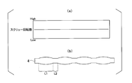
- FIG. (A) shows the number of rotations (constant) of the screw rod 52, and (b) shows the finished state of the sealing material 4 when the number of rotations of the screw rod 52 is constant and the sealing material 4 is applied .
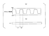
- (A) shows the number of rotations (variation) of the screw rod 52, and (b) shows the finished state of the sealing material 4 when the number of rotations of the screw rod 52 is varied to apply the sealing material 4 .
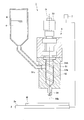
- FIG. 1 is a schematic configuration view showing the configuration of a coating apparatus 1 used for manufacturing a liquid crystal display device.
- FIG. 2 is an enlarged view of the main part of the dispenser unit 5.
- the coating device 1 of the present embodiment shown in FIG. 1 is a screw type coating device used in a method of manufacturing a liquid crystal display device.
- the coating apparatus 1 applies the stage 2 on which the substrate W, which is an application target of the sealing material (viscous material) 4, is horizontally placed, and the substrate (application target) W placed on the stage 2. It comprises at least a dispenser unit 5 for discharging the sealing material 4 and a sealing material reservoir 6 for storing the sealing material 4 supplied to the dispenser unit 5.
- the coating apparatus 1 further includes a moving mechanism that moves the dispenser unit 5 and the stage 2 relative to each other, and a control device 7 that controls the operation of the stage 2 and the dispenser unit 5.
- a moving mechanism that moves the dispenser unit 5 and the stage 2 relative to each other
- a control device 7 that controls the operation of the stage 2 and the dispenser unit 5.
- illustration and description are abbreviate
- the dispenser unit 5 includes a cylinder 51, a screw rod 52 disposed in the cylinder 51, a motor 53 for rotating the screw rod 52, and a discharge communicating with the lower end side of the cylinder 51. And a nozzle 54.
- the cylinder 51 is disposed above the stage 2 and extends in a direction perpendicular to the substrate mounting surface 2 a of the stage 2.
- the cylinder 51 is a hollow member having a liquid chamber 51A in which the screw rod 52 is accommodated.
- the central axis of the screw rod 52 and the central axis of the cylinder 51 coincide with each other.
- the clearance between the peripheral wall 51b of the cylinder 51 and the screw rod 52 in the liquid chamber 51A is filled with the sealing material 4 supplied from the sealing material reservoir 6.
- a supply port 51c communicating with the seal material storage section 6 is formed in the peripheral wall 51b of the cylinder 51, and the seal material 4 supplied from the seal material storage section 6 through the supply port 51c is formed in the cylinder 51. It flows into the fluid chamber 51A.
- a tapered portion 51d which decreases in diameter toward the tip end in the axial direction (-Z direction), and in order to discharge the seal material 4 in the liquid chamber 51A at the center of the tip.
- the discharge nozzle 54 is provided.
- the screw rod 52 is rotatably disposed in the cylinder 51.
- the screw rod 52 is formed of a rod-like shaft 52A in a solid cylindrical shape, a single spiral convex streak 52B provided on the outer peripheral surface 52a of the shaft 52A, and the spiral convex streak 52B. And a groove 52C.
- the helical angle ⁇ of the ridge portion 52B with respect to the central axis is 10 degrees or more and 80 degrees or less.
- At the lower end of the screw rod 52 there is a tapered portion 52d that decreases in diameter toward the tip end in the axial direction (-Z direction), and the tapered surface is substantially parallel to the tapered surface of the tapered portion 51d of the cylinder 51 described above.
- Such a screw rod 52 conveys the sealing material 4 (FIG. 1) from the liquid chamber 51A filled with the sealing material 4 into the spiral groove 52C toward the discharge nozzle 54. That is, when the screw rod 52 rotates around the rotation axis O, the seal material 4 in the liquid chamber 51A is conveyed by the convex streak portion 52B so as to be pushed out toward the discharge nozzle 54 in the axial direction.
- the discharge nozzle 54 is a nozzle for discharging the sealing material 4 in the liquid chamber 51A of the cylinder 51 transported by the screw rod 52 onto the substrate W placed on the stage 2.
- the discharge nozzle 54 is disposed concentrically with the cylinder 51 and the screw rod 52.
- the discharge port 54 a of the discharge nozzle 54 is parallel to the cross section of the screw rod 52 in the direction intersecting with the axial direction. Therefore, the sealing material 4 fed in the axial direction by the screw rod 52 is smoothly discharged from the discharge port 54 a located on the extension thereof.
- the rotational speed of the screw rod 52 can be determined according to the position of the ridge 52B. As a result, the pulsation of the sealing material 4 is suppressed, and the sealing material 4 can be discharged in a fixed amount.
- the control device 7 coordinates the operation of the moving mechanism and the operation of the dispenser unit 5.
- the controller 7 changes the rotational speed of the screw rod 52 when performing coating by relatively moving the dispenser unit 5 and the stage 2 at a constant speed.
- the relative velocity between the dispenser unit 5 and the stage 2 may not always be constant, and may be appropriately changed in accordance with straight line drawing, curve drawing, corner drawing, and the like.
- FIG. 3A shows the number of rotations (constant) of the screw rod 52
- FIG. 3B shows the finished state of the sealing material 4 when the number of rotations of the screw rod 52 is constant and the sealing material 4 is applied.
- FIG. 4 (a) shows the number of rotations (variation) of the screw rod 52
- FIG. 3 (b) shows the finished state of the sealing material 4 when the number of rotations of the screw rod 52 is varied to apply the sealing material 4
- the coating device 1 of the present embodiment is used to form a rectangular shape on one substrate W of a pair of substrates disposed to face each other so as to surround a display area. Apply a line to form a closed loop pattern.
- an initial filling operation is performed first, and then a coating operation is performed.
- the initial filling operation is to fill the sealing material 4 without leaving air in the spiral gap formed between the circumferential wall 51 b of the cylinder 51 and the screw rod 52 by rotating the screw rod 52.
- the application operation is an operation for continuously extruding the sealing material 4 corresponding to the amount of rotation of the screw rod 52 from the discharge nozzle 54 to draw a desired pattern on the substrate W.
- the control device 7 of the coating apparatus 1 drives the motor 53 to rotate the screw rod 52 in the cylinder 51, thereby sealing the sealing material 4 between the peripheral wall 51b of the cylinder 51 and the spiral groove 52C.
- the substrate W is pushed out in the axial direction by the ridges 52B and transferred from the opening 52e of the groove 52C formed in the taper 52d to the discharge nozzle 54 side, and the substrate W mounted on the stage 2 from the discharge nozzles 54 Discharge toward the By applying the sealing material 4 discharged from the discharge nozzle 54 on the substrate W, a closed seal pattern is formed.
- the seal material 4 is pushed out by the rotation of the screw rod 52.
- the first position A1 and the second position A2 on the both sides in the radial direction of the protrusion 52B. Since the distances L1 and L2 (FIG. 1) between each of the above and the discharge port 54a of the discharge nozzle 54 are different, as shown in FIG.
- the extrusion pressure fluctuates, and the discharge amount of the sealing material 4 becomes uneven.
- the rotational speed of the motor 53 is varied according to the rotational position of the screw rod 52, that is, the extrusion pressure described above. Control to change the Here, at a position where the extrusion pressure at the screw rod 52 is low (the resistance of the sealing material 4 is low), the rotation number is increased to increase the discharge amount, and at a position where the extrusion pressure is high (the resistance of the sealing material 4 is high) Control to reduce the discharge amount by lowering As a result, as shown in FIG. 4B, the variation in the discharge amount of the sealing material 4 was improved, and the sealing material 4 could be applied with a high degree of straightness.
- the discharge amount per unit time of the sealing material 4 discharged from the dispenser unit 5 is proportional to the number of rotations of the screw rod 52. Therefore, by adjusting the rotation speed of the screw rod 52, it is possible to adjust so that the discharge amount of the sealing material 4 discharged from the discharge nozzle 54 becomes constant.
- the coating device 1 of this embodiment may be equipped with the detection means which detects the rotational position of the screw rod 52. As shown in FIG. Although various means can be mentioned as a detection means, for example, the first position A1 and the second position A2 on both sides in the radial direction of the ridge 52B of the screw rod 52 are detected using a sensor or the like, and the result is The control device 7 may control the number of rotations of the motor 53.
- the number of rotations of the screw rod 52 is controlled in accordance with the rotational position of the screw rod 52 (resistance of the seal member 4), so that the seal material 4 can be discharged at a constant discharge rate. Since it can be made to project stably, the pulsation of the amount of discharge can be suppressed and the sealing material 4 can be drawn linearly. As a result, the adhesive strength is constant throughout the sealing material 4 and the panel strength can be sufficiently secured. Further, as the straightness of the sealing material 4 applied on the substrate W is improved, the sealing material 4 can be thinned. Therefore, since it can be favorably apply
- Some aspects of the present invention can be applied to a coating apparatus, a coating method, and the like that are required to improve the variation in the coating amount of the sealing material.
Landscapes
- Coating Apparatus (AREA)
- Liquid Crystal (AREA)
Abstract
L'appareil d'application selon un mode de réalisation de la présente invention est pourvu d'une unité de distribution pour faire sortir un matériau visqueux vers un objet d'application, et d'un dispositif de commande pour commander l'unité de distribution, l'unité de distribution étant pourvue : d'un cylindre ayant une chambre de liquide ; d'une buse de sortie pour faire sortir le matériau visqueux dans la chambre de liquide vers l'objet d'application, la buse de sortie étant disposée sur une extrémité inférieure du cylindre ; d'une tige filetée pour faire tourner et ainsi envoyer le matériau visqueux dans la chambre de liquide vers la buse de sortie dans la direction axiale de la tige filetée, la tige filetée étant disposée dans la chambre de liquide ; et d'un moteur pour amener la tige filetée à tourner ; la tige filetée comportant un arbre, une partie saillie hélicoïdale disposée sur une surface périphérique externe de l'arbre, et une partie rainure hélicoïdale formée par la partie saillie, et le dispositif de commande commandant la vitesse du moteur conformément à la position de rotation de la tige filetée.
Applications Claiming Priority (2)
| Application Number | Priority Date | Filing Date | Title |
|---|---|---|---|
| JP2017135586 | 2017-07-11 | ||
| JP2017-135586 | 2017-07-11 |
Publications (1)
| Publication Number | Publication Date |
|---|---|
| WO2019013208A1 true WO2019013208A1 (fr) | 2019-01-17 |
Family
ID=65001391
Family Applications (1)
| Application Number | Title | Priority Date | Filing Date |
|---|---|---|---|
| PCT/JP2018/026054 Ceased WO2019013208A1 (fr) | 2017-07-11 | 2018-07-10 | Appareil d'application et procédé d'application |
Country Status (1)
| Country | Link |
|---|---|
| WO (1) | WO2019013208A1 (fr) |
Cited By (1)
| Publication number | Priority date | Publication date | Assignee | Title |
|---|---|---|---|---|
| CN119634150A (zh) * | 2024-10-30 | 2025-03-18 | 西安建筑科技大学 | 一种摩擦涂覆耐高温高熵合金涂层制备装置及方法 |
Citations (5)
| Publication number | Priority date | Publication date | Assignee | Title |
|---|---|---|---|---|
| JPH0449108A (ja) * | 1990-06-18 | 1992-02-18 | Iwashita Eng Kk | スクリュー式吐出装置 |
| JP2005185916A (ja) * | 2003-12-25 | 2005-07-14 | Sony Corp | スクリュー式ディスペンサー |
| WO2006118088A1 (fr) * | 2005-04-26 | 2006-11-09 | Shibaura Mechatronics Corporation | Dispositif et procede d’application de pate |
| JP2009039661A (ja) * | 2007-08-09 | 2009-02-26 | Shibaura Mechatronics Corp | ペースト塗布装置及びペースト塗布方法 |
| JP2009050828A (ja) * | 2007-08-29 | 2009-03-12 | Shibaura Mechatronics Corp | ペースト塗布装置及びペースト塗布方法 |
-
2018
- 2018-07-10 WO PCT/JP2018/026054 patent/WO2019013208A1/fr not_active Ceased
Patent Citations (5)
| Publication number | Priority date | Publication date | Assignee | Title |
|---|---|---|---|---|
| JPH0449108A (ja) * | 1990-06-18 | 1992-02-18 | Iwashita Eng Kk | スクリュー式吐出装置 |
| JP2005185916A (ja) * | 2003-12-25 | 2005-07-14 | Sony Corp | スクリュー式ディスペンサー |
| WO2006118088A1 (fr) * | 2005-04-26 | 2006-11-09 | Shibaura Mechatronics Corporation | Dispositif et procede d’application de pate |
| JP2009039661A (ja) * | 2007-08-09 | 2009-02-26 | Shibaura Mechatronics Corp | ペースト塗布装置及びペースト塗布方法 |
| JP2009050828A (ja) * | 2007-08-29 | 2009-03-12 | Shibaura Mechatronics Corp | ペースト塗布装置及びペースト塗布方法 |
Cited By (2)
| Publication number | Priority date | Publication date | Assignee | Title |
|---|---|---|---|---|
| CN119634150A (zh) * | 2024-10-30 | 2025-03-18 | 西安建筑科技大学 | 一种摩擦涂覆耐高温高熵合金涂层制备装置及方法 |
| CN119634150B (zh) * | 2024-10-30 | 2025-09-23 | 西安建筑科技大学 | 一种摩擦涂覆耐高温高熵合金涂层制备装置及方法 |
Similar Documents
| Publication | Publication Date | Title |
|---|---|---|
| KR101523294B1 (ko) | 액체 재료의 도포 장치, 도포 방법 및 프로그램이 기억된 기억 매체 | |
| JP6804850B2 (ja) | 塗布装置及び塗布方法 | |
| CN101362125A (zh) | 涂膏装置以及涂膏方法 | |
| JP5304902B2 (ja) | 電池の電極の製造方法および電池の電極の製造装置 | |
| EP1872861A2 (fr) | Procédé et appareil d'application de solutions de revêtements avec racle cylindrique | |
| WO2015033535A1 (fr) | Système d'application de fluide et procédé d'application de fluide | |
| JP2009050828A (ja) | ペースト塗布装置及びペースト塗布方法 | |
| WO2019013208A1 (fr) | Appareil d'application et procédé d'application | |
| JP6408608B2 (ja) | 塗布装置と塗布方法、塗布ユニット | |
| WO2022050077A1 (fr) | Dispositif de revêtement | |
| JP2008253867A (ja) | 塗布装置 | |
| JP5251233B2 (ja) | 筒体の塗装方法 | |
| JP2021098154A (ja) | 塗布装置及び塗布方法 | |
| ES2982962T3 (es) | Procedimiento y dispositivo de deposición de un cordón de fluido viscoso a alta velocidad | |
| JP2016067974A (ja) | 塗布装置および塗布方法 | |
| JP5335319B2 (ja) | 塗布装置及び塗布方法 | |
| JP2002079164A (ja) | エクストルージョン型ノズル、塗布装置、並びにプラズマディスプレイパネル前面板の誘電体層の製造方法 | |
| JP5127127B2 (ja) | 塗膜形成方法 | |
| JP6901616B2 (ja) | 塗布装置及び塗布方法 | |
| JP2006035179A (ja) | 塗工装置 | |
| JP4868404B2 (ja) | 処理方法および処理装置 | |
| JP2021186692A (ja) | 樹脂の塗布制御方法及び樹脂塗布装置 | |
| JP4619161B2 (ja) | 塗布装置 | |
| JP3161694U (ja) | 塗工装置 | |
| KR20010109589A (ko) | 립 코터형 도장장치 |
Legal Events
| Date | Code | Title | Description |
|---|---|---|---|
| 121 | Ep: the epo has been informed by wipo that ep was designated in this application |
Ref document number: 18831032 Country of ref document: EP Kind code of ref document: A1 |
|
| NENP | Non-entry into the national phase |
Ref country code: DE |
|
| 122 | Ep: pct application non-entry in european phase |
Ref document number: 18831032 Country of ref document: EP Kind code of ref document: A1 |
|
| NENP | Non-entry into the national phase |
Ref country code: JP |