WO2019013262A1 - Procédé de fabrication d'une poutrelle d'acier à profil en h - Google Patents
Procédé de fabrication d'une poutrelle d'acier à profil en h Download PDFInfo
- Publication number
- WO2019013262A1 WO2019013262A1 PCT/JP2018/026218 JP2018026218W WO2019013262A1 WO 2019013262 A1 WO2019013262 A1 WO 2019013262A1 JP 2018026218 W JP2018026218 W JP 2018026218W WO 2019013262 A1 WO2019013262 A1 WO 2019013262A1
- Authority
- WO
- WIPO (PCT)
- Prior art keywords
- hole type
- hole
- rolled
- flange
- roll
- Prior art date
- Legal status (The legal status is an assumption and is not a legal conclusion. Google has not performed a legal analysis and makes no representation as to the accuracy of the status listed.)
- Ceased
Links
Images





Classifications
-
- B—PERFORMING OPERATIONS; TRANSPORTING
- B21—MECHANICAL METAL-WORKING WITHOUT ESSENTIALLY REMOVING MATERIAL; PUNCHING METAL
- B21D—WORKING OR PROCESSING OF SHEET METAL OR METAL TUBES, RODS OR PROFILES WITHOUT ESSENTIALLY REMOVING MATERIAL; PUNCHING METAL
- B21D47/00—Making rigid structural elements or units, e.g. honeycomb structures
- B21D47/01—Making rigid structural elements or units, e.g. honeycomb structures beams or pillars
-
- B—PERFORMING OPERATIONS; TRANSPORTING
- B21—MECHANICAL METAL-WORKING WITHOUT ESSENTIALLY REMOVING MATERIAL; PUNCHING METAL
- B21B—ROLLING OF METAL
- B21B1/00—Metal-rolling methods or mills for making semi-finished products of solid or profiled cross-section; Sequence of operations in milling trains; Layout of rolling-mill plant, e.g. grouping of stands; Succession of passes or of sectional pass alternations
- B21B1/08—Metal-rolling methods or mills for making semi-finished products of solid or profiled cross-section; Sequence of operations in milling trains; Layout of rolling-mill plant, e.g. grouping of stands; Succession of passes or of sectional pass alternations for rolling structural sections, i.e. work of special cross-section, e.g. angle steel
- B21B1/088—H- or I-sections
-
- B—PERFORMING OPERATIONS; TRANSPORTING
- B21—MECHANICAL METAL-WORKING WITHOUT ESSENTIALLY REMOVING MATERIAL; PUNCHING METAL
- B21H—MAKING PARTICULAR METAL OBJECTS BY ROLLING, e.g. SCREWS, WHEELS, RINGS, BARRELS, BALLS
- B21H8/00—Rolling metal of indefinite length in repetitive shapes specially designed for the manufacture of particular objects, e.g. checkered sheets
Definitions
- the present invention relates to a method of manufacturing an H-shaped steel, for example, using a slab having a rectangular cross section as a raw material.
- H-shaped steel materials such as slabs and blooms extracted from a heating furnace are shaped into a roughly shaped material (a so-called dog-bone shaped material to be rolled) by a rough rolling mill (BD). Subsequently, the thickness of the web or flange of the above-mentioned rough profile is reduced by an intermediate universal rolling mill. At the same time, width reduction and forging and shaping of the end face are applied to the flange of the material to be rolled by an edger rolling mill adjacent to the intermediate universal rolling mill. Then, the H-shaped steel product is shaped by the finishing universal rolling mill.
- BD rough rolling mill
- Patent Document 1 forms an interrupt without constraining the upper and lower end portions (slab end surface) of the material to be rolled, and performs the edging rolling to press the interrupt.
- Techniques for spreading are disclosed. According to this technique, it is possible to increase the thickness of the flange in accordance with the rolling reduction of the edging rolling.
- Patent Document 2 discloses a technique for performing edging rolling in which a reduction is applied in a state in which both sides of upper and lower end portions (slab end faces) of a material to be rolled are restrained, and spreading interrupts. According to this technique, since pressure reduction is performed by restraining both the upper and lower end portions of the material to be rolled, it is possible to create a buildup of thickness at the tip end of the flange and achieve thickening.
- An object of the present invention is to deeply interrupt the end face of a material such as a slab with an acute-tipped protrusion in the rough rolling process using a hole type for producing H-shaped steel.
- An object of the present invention is to provide a method of manufacturing an H-shaped steel capable of manufacturing an H-shaped steel product having a thicker flange thickness as compared to the conventional method when performing a process of sequentially bending the flange portion formed thereby.
- the plurality of hole molds are provided with one or more projections for forming a divided portion at the end of the material to be rolled by making an interruption vertically to the width direction of the material to be rolled An interrupting hole type, and a plurality of bending hole types in which a projecting portion is formed which abuts on the interrupt and which sequentially bends divided portions formed in the interrupting hole type; and the last interrupting hole of the interrupting hole type
- the projection formed in the mold comprises a tapered tip having a predetermined tip angle, and a root located at the root of the tip and having a tapered shape with a gentle slope compared to the tip.
- the taper angle of the root portion may be 60 ° or more, and may be equal to or less than a tip angle of a protrusion formed in the first hole type of the bent hole types.
- the thickness of the flange of the material to be rolled which is formed in the frontmost one of the bending hole types may be more than 160 mm.
- the root portion with respect to the flange contact width B in the last interrupt hole type of the interrupt hole type may be configured such that a contact width ratio L / B which is a ratio of the width L is 0.20 or more.
- the reduction may be performed in a state in which the end face of the material to be rolled and the hole circumferential surface are in contact in formation of at least one pass or more.
- the interrupting hole mold may be provided with a hole-shaped side surface that abuts against the left and right side surfaces of the material to be rolled and restrains the material to be rolled from the left and right.
- the end face of the material such as slab is deeply interrupted by the projection having an acute tip shape, and is thereby formed.
- the process of sequentially bending the flange portion it is possible to manufacture an H-shaped steel product having a thicker flange thickness than in the prior art.
- FIG. 1 is an explanatory view of a production line T of H-shaped steel including the rolling equipment 1 according to the present embodiment.
- a heating furnace 2 a sizing mill 3, a rough rolling mill 4, an intermediate universal rolling mill 5, and a finishing universal rolling mill 8 are arranged in order from the upstream side in a production line T.
- an edger rolling mill 9 is provided in proximity to the intermediate universal rolling mill 5.
- steel materials in the production line T may be collectively referred to as “rolled material A” for the sake of description, and the shapes thereof may be illustrated using broken lines, oblique lines, and the like as appropriate in each drawing.
- a material to be rolled A such as a slab 11 extracted from the heating furnace 2 is roughly rolled in the sizing mill 3 and the rough rolling mill 4.
- intermediate rolling is performed in the intermediate universal rolling mill 5.
- an edger rolling machine 9 applies a pressure to an end portion or the like of a material to be rolled (a flange portion 80 described later) as needed.
- approximately 4 to 6 hole types are engraved on the rolls of the sizing mill 3 and the rough rolling mill 4, and the rough H shape is formed by reverse rolling through several passes via these.
- the material 13 is shaped.
- a plurality of passes of reduction are applied to the H-shaped rough profile 13 using a rolling mill row consisting of two rolling mills of the intermediate universal rolling mill 5-edger rolling mill 9, and the intermediate material 14 is formed. Ru. Then, the intermediate material 14 is finish-rolled into a product shape in a finish universal rolling mill 8 to produce an H-shaped steel product 16.
- FIGS. 2 to 7 are schematic explanatory views of a sizing mill 3 for performing a rough rolling process and a hole type provided on the rough rolling mill 4.
- the first through fourth hole molds to be described may be, for example, all cut in the sizing mill 3, and the sizing mill 3 and the rough rolling mill 4 may have five first through fifth hole molds.
- the hole type may be divided and engraved. That is, the first through fourth hole types may be provided across both the sizing mill 3 and the roughing mill 4 or may be provided in either one of the rolling mills.
- shaping is performed in one or more passes in each of these hole types.
- the basic configuration of the hole type to be engraved is described by exemplifying a six-hole type, but the number of the hole types is not necessarily the six-hole type, A plurality of six or more hole types may be used. That is, any hole-type configuration suitable for forming the H-shaped rough member 13 may be used.
- FIGS. 2 to 7 a schematic final pass shape of the material to be rolled A at the time of formation in each hole type is illustrated by a broken line.
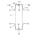
- FIG. 2 is a schematic explanatory view of the first hole type K1.
- the first hole type K1 is engraved on the upper hole type roll 20 and the lower hole type roll 21 which are a pair of horizontal rolls.
- the material to be rolled A is pressed and shaped in the roll gap of the upper hole type roll 20 and the lower hole type roll 21.
- a protrusion 25 which protrudes toward the inside of the hole type is formed.
- a projection 26 projecting toward the inside of the hole type is formed.
- the protrusions 25 and 26 have a tapered shape, and the dimensions such as the projection length thereof are equal to each other by the protrusions 25 and the protrusions 26.
- the height (protruding length) of the protrusions 25 and 26 is h1 and the tip angle is ⁇ 1a.
- the protrusions 25 and 26 are pressed against the upper and lower end portions (slab end faces) of the material to be rolled A, and the interruptions 28 and 29 are formed.
- the first hole type K1 is also referred to as a "grooved hole type" because it is a hole type in which a groove (an interruption 28, 29) is provided on the end face of the slab.
- a tip end angle (also referred to as a wedge angle) ⁇ 1a of the protrusions 25 and 26 be, for example, 25 ° or more and 40 ° or less.
- the hole width of the first hole type K1 be substantially equal to the thickness of the material to be rolled A (that is, the slab thickness).
- the left-right centering property of the material to be rolled A is suitably secured by making the width of the hole mold at the tip of the protrusions 25 and 26 formed in the first hole mold K1 equal to the slab thickness. Be done.
- the above-mentioned protrusions are formed at the upper and lower end portions (slab end faces) of the material to be rolled A at the time of shaping with the first hole-type K1.
- the hole-shaped side wall (side wall) is in contact with the material to be rolled A, and a part of the hole-shaped side wall (side wall) is in contact with the material to be rolled A, and the first hole type is formed on the upper and lower ends of the slab divided into four elements (portions) by the interruptions 28 and 29. It is preferable that positive pressure reduction not be performed on the top and bottom surfaces of K1. This is because the reduction by the upper surface and the bottom surface of the hole mold causes the elongation of the material to be rolled A in the longitudinal direction, and reduces the generation efficiency of the flange (a flange portion 80 described later).
- the protrusions 25 and 26 are pressed against the upper and lower end portions (slab end surfaces) of the material to be rolled A, and the pressure reduction at the protrusions 25 and 26 when the interruptions 28 and 29 are formed.
- the amount (wedge tip reduction amount) is made sufficiently larger than the reduction amount (slab end surface reduction amount) at the upper and lower ends of the slab, whereby the interruptions 28 and 29 are formed.
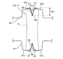
- FIG. 3 is a schematic explanatory view of a 2-1 hole type K2-1.
- the No. 2-1 hole type K 2-1 is engraved on the upper hole type roll 30 and the lower hole type roll 31 which are a pair of horizontal rolls.
- On the peripheral surface of the upper hole type roll 30 that is, the upper surface of the 2-1st hole type K2-1
- a protrusion 35 which protrudes toward the inside of the hole type is formed.
- On the circumferential surface of the lower hole type roll 31 that is, the bottom surface of the 2-1st hole type K2-1
- a projection 36 which protrudes toward the inside of the hole type is formed.
- the protrusions 35 and 36 have a tapered shape, and the dimensions such as the projection length thereof are equal to each other by the protrusions 35 and 36. It is desirable that the tip end angles of the protrusions 35 and 36 be a wedge angle ⁇ 1 b of 25 ° or more and 40 ° or less.
- the wedge angle .theta.1a of the first hole type K1 secures the thickness of the tip of the flange equivalent portion, enhances the inductive property, and secures the stability of the rolling, the second 2-1 hole type K2 of the latter stage It is preferable that the angle be the same as the wedge angle ⁇ 1 b of ⁇ 1.
- the height (protruding length) h2a of the protrusions 35 and 36 is set to be higher than the height h1 of the protrusions 25 and 26 of the first hole type K1, and h2a> h1.
- the material to be rolled A after the first hole type K1 passing is further shaped in the roll gap between the upper hole type roll 30 and the lower hole type roll 31.
- the height h2a of the protrusions 35 and 36 formed in the 2-1 hole type K2-1 is higher than the height h1 of the protrusions 25 and 26 formed in the first hole type K1. Further, the penetration length to the upper and lower end portions (slab end faces) of the material to be rolled A is also longer in the case of the 2-1 hole type K2-1.
- the penetration depth of the protrusions 35 and 36 into the material to be rolled A in the second hole type K 2-1 is the same as the height h 2 a of the protrusions 35 and 36.
- the penetration depth h2a of the is h1 ' ⁇ h2a.
- an angle ⁇ f formed by the upper surface 30a, 30b and the lower surface 31a, 31b of the material to be rolled A facing the upper and lower end portions (slab end surface) of the material to be rolled A and the inclined surfaces of the protrusions 35, 36 is shown in FIG.
- the four locations shown are each configured at about 90 ° (approximately right angle).
- the shaping is performed so that the interrupts 28, 29 formed in the single-hole type K1 are deeper, and the interrupts 38, 39 are formed.
- the 2-1 hole type K2-1 is also referred to as an "interrupt hole type".
- the formation in the 2-1 hole type K2-1 is performed by multiple passes.
- shaping is performed such that the upper and lower end portions (slab end faces) of the material to be rolled A, the hole top surfaces 30a and 30b and the hole bottom surfaces 31a and 31b are in contact in the final pass. It will be.
- This is a portion corresponding to the flange (a portion corresponding to the flange portion 80 described later), assuming that the upper and lower end portions of the material to be rolled A do not contact the inside of the hole type in all the passes in the 2-1st hole type K2-1. It is because there is a possibility that a shape defect may occur such as forming asymmetrically left and right), and there is a problem in terms of threadability.
- FIG. 4 is a schematic explanatory view of a 2-2 hole type K2-2.
- the 2nd-2 hole type K2-2 is engraved on the upper hole type roll 40 and the lower hole type roll 41 which are a pair of horizontal rolls.
- a projection 45 which protrudes toward the inside of the hole type is formed.
- a projection 46 which protrudes toward the inside of the hole type is formed.
- the projections 45 and 46 have a tapered shape, and the dimensions such as the projection length thereof are equal to each other by the projections 45 and the projections 46.
- the tip angle of these projections 45 and 46 is a wedge angle ⁇ 1 b of 25 ° or more and 40 ° or less, and is preferably designed to be the same angle as the wedge angle of the above-mentioned 2-1 hole type K 2-1.
- the height (protrusion length) h2b of the protrusions 45 and 46 is configured to be higher than the height h2a of the protrusions 35 and 36 of the above-described second through-hole type K2-1, and h2b> h2a. .
- the rolled material A after passing through the above-described second through-hole type K2-1 is further shaped in the roll gap between the upper-hole type roll 40 and the lower-hole type roll 41.
- the height h2b of the protrusions 45 and 46 formed in the 2nd-2nd hole type K2-2 It is higher. Further, the penetration length into the upper and lower end portions (slab end faces) of the material to be rolled A is also longer in the second 2-2 hole type K2-2. The penetration depth of the projections 45, 46 into the material to be rolled A in the second 2-2 hole type K2-2 is the same as the height h2b of the projections 45, 46.
- the penetration depth h2b into the material A is in a relationship of h2a ⁇ h2b.
- an angle ⁇ f formed by the upper surface 40a, 40b and the lower surface 41a, 41b of the material to be rolled A facing the upper and lower end portions (slab end surface) of the material to be rolled The four locations shown are each configured at about 90 ° (approximately right angle).
- the 2-2nd hole type K2-2 since the penetration length of the projection when pressed against the upper and lower end portions (slab end face) of the material to be rolled A is long, in the 2-2nd hole type K2-2, The shaping is performed so that the interrupts 38, 39 formed in the 2-hole type K2-1 are deeper, and the interrupts 48, 49 are formed.
- the second hole type K2-2 is also referred to as an "interrupt hole type".
- the flange piece width at the end of the flange shaping process in the rough rolling process is determined based on the dimensions of the interruptions 48 and 49 formed here.
- the formation in the 2-2 hole type K2-2 is performed by multiple passes.
- shaping is performed such that the upper and lower end portions (slab end faces) of the material to be rolled A, the hole upper surface 40a, 40b and the hole bottom surface 41a, 41b are in contact in the final pass. It will be. This is because assuming that the upper and lower end portions of the material to be rolled A do not make contact with the inside of the hole type in all the passes in the 2-2nd hole type K2-2, the flange equivalent portion (flange portion 80 described later) is left-right asymmetric There is a possibility that the shape defect such as being formed may occur, and there is a problem in the material passing property.
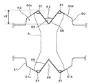
- FIG. 5 is a schematic explanatory view of the third hole type K3.
- the third hole type K3 is engraved on the upper hole type roll 50 and the lower hole type roll 51 which are a pair of horizontal rolls.
- a projection 55 which protrudes toward the inside of the hole type is formed.
- a protrusion 56 that protrudes toward the inside of the hole type is formed.
- the protrusions 55 and 56 have a tapered shape, and the dimensions such as the projection length thereof are equal to each other by the protrusions 55 and the protrusions 56.
- the tip end angle ⁇ 2 of the protrusions 55 and 56 is wider than the angle ⁇ 1 b.
- the penetration depth h3 of the protrusions 55 and 56 into the material to be rolled A is shorter than the penetration depth h2b of the protrusions 45 and 46 (that is, h3 ⁇ h2b).
- the angle ⁇ 2 is preferably, for example, 70 ° or more and 110 ° or less.
- an angle ⁇ f formed by the upper surface 50a, 50b and the lower surface 51a, 51b of the material to be rolled A facing the upper and lower end portions (slab end surface) and the inclined surface of the protrusions 55, 56 is shown in FIG. The four locations shown are each configured at about 90 ° (approximately right angle).
- the second to third hole type K2-2 passes through the material to be rolled A, and the second to the bottom end (slab end face) of the material to be rolled A
- the interruptions 48 and 49 formed in the two-hole type K2-2 become interruptions 58 and 59 when the projections 55 and 56 are pressed. That is, in the final pass in the formation in the third hole type K3, the deepest portion angle (hereinafter also referred to as an interrupt angle) of the interrupts 58 and 59 is ⁇ 2.
- shaping is performed such that a divided portion (portion corresponding to the flange portion 80 described later) shaped together with the formation of the interruptions 48 and 49 in the 2nd-2 hole type K2-2 is bent outward.
- the third hole type K3 is also referred to as a "bent hole type".
- mold K3 shown in FIG. 5 is performed by at least 1 pass or more. At least one of the passes is performed in a state in which the upper and lower end portions (slab end faces) of the material to be rolled A are in contact with the inside of the hole mold (the top and bottom of the third hole mold K3). In the state where the upper and lower end portions (slab end faces) of the material to be rolled A and the inside of the hole mold are in contact with each other, light reduction of the end portions is preferably performed.
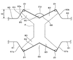
- FIG. 6 is a schematic explanatory view of the fourth hole type K4.
- the fourth hole type K4 is engraved on the upper hole type roll 60 and the lower hole type roll 61, which are a pair of horizontal rolls.
- a projection 65 projecting toward the inside of the hole type is formed on the circumferential surface of the upper hole type roll 60 (that is, the upper surface of the fourth hole type K4).
- a projection 66 projecting toward the inside of the hole type is formed on the circumferential surface of the lower hole type roll 61 (that is, the bottom surface of the fourth hole type K4).
- the projections 65 and 66 have a tapered shape, and the dimensions such as the projection length thereof are equal to each other by the projections 65 and the projections 66.
- the tip end angle ⁇ 3 of the protrusions 65 and 66 is wider than the angle ⁇ 2.
- the penetration depth h4 of the projections 65 and 66 into the material to be rolled A is shorter than the penetration depth h3 of the projections 55 and 56 (that is, h4 ⁇ h3).
- the angle ⁇ f formed by the upper surfaces 60a and 60b and the lower surfaces 61a and 61b of the material to be rolled A and the inclined surfaces of the protrusions 65 and 66 is the third one. Similar to the hole type K3, all four places shown in FIG. 6 are configured at about 90 ° (approximately right angle).
- the interruptions 58 and 59 formed in the third hole type K3 at the upper and lower end portions (slab end faces) of the material to be rolled A after passing the third hole type K3 are used.
- the projections 65 and 66 are pushed and spread out to form interruptions 68 and 69, respectively. That is, in the final pass of the formation in the fourth hole type K4, the deepest part angle (hereinafter also referred to as an interruption angle) of the interruptions 68 and 69 is ⁇ 3.
- the third hole type K3 is shaped such that the divided portion (portion corresponding to the flange portion 80 described later) shaped together with the formation of the interruptions 58 and 59 is further bent outward.
- the fourth hole type K4 is also referred to as a "bent hole type".
- the portions of the upper and lower end portions of the material to be rolled A shaped in this manner are portions corresponding to the flanges of the later H-shaped steel product, and are referred to as flange portions 80 in the present specification.
- the formation in the fourth hole type K4 shown in FIG. 6 is performed by at least one pass or more. At least one of the passes is performed in a state in which the upper and lower end portions (slab end faces) of the material to be rolled A are in contact with the inside of the hole mold (the top and bottom of the fourth hole mold K4). In the state where the upper and lower end portions (slab end faces) of the material to be rolled A and the inside of the hole mold are in contact with each other, light reduction of the end portions is preferably performed.
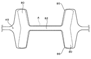
- FIG. 7 is a schematic explanatory view of the fifth hole type K5.
- the fifth hole type K5 is composed of an upper hole type roll 85 and a lower hole type roll 86 which are a pair of horizontal rolls.
- the material to be rolled A shaped up to the fourth hole type K4 is rotated 90 ° or 270 °, and up to the fourth hole type K4, the material to be rolled is A
- the flange portions 80 located at the upper and lower ends are arranged to be on the rolling pitch line.
- the flange width is adjusted by reducing the pressure of the web portion 82 which is a connection portion connecting the two flange portions 80 and pressing the flange front end portion of the flange portion 80.
- a so-called dog-bone shaped H-shaped rough section (H-shaped rough section 13 shown in FIG. 1) is formed.
- the fifth hole type K5 is also referred to as a "web reduced thickness hole type” or a "flat shaped hole type” because the fifth hole type K5 presses the web portion 82 to reduce the thickness.
- mold K5) is performed by 1 or arbitrary multiple passes.
- a multi-pass reverse rolling is performed on the H-shaped rough section 13 shaped in this way, using a rolling mill row consisting of two rolling mills of an intermediate universal rolling mill 5-edger rolling mill 9 which is a known rolling mill. Is added, and the intermediate material 14 is shaped. Then, the intermediate material 14 is finish-rolled into a product shape in a finish universal rolling mill 8 to produce an H-shaped steel product 16 (see FIG. 1).
- the upper and lower end portions (slab end faces) of the material to be rolled A are interrupted, and the interruptions are divided into left and right by these interruptions.
- a process is performed such that the portion is bent left and right to form the flange portion 80. This makes it possible to widen the flange width and form the H-shaped rough section 13 as a result, as compared with the conventional rough rolling method in which the slab end face is always pressed, and as a result, the final product has a large flange width. (H-shaped steel) can be manufactured.
- the shape of the flange portion 80 of the material to be rolled A shaped by the above-described first through fourth hole types K1 to K4 is the conventional manufacture. Compared with the shape of the flange part before the flat hole type shaping
- the flange 80 in the manufacturing process may be thicker than before.
- the occurrence of a gutter on the outer surface of the flange portion 80 is confirmed at the time of bending and shaping with the third hole type K3, and further deterioration in biting property is also confirmed. It is done. It is estimated that the sliding gutter is generated by the metal of the flange portion 80 being pulled down in the reduction direction by the frictional force of the roll at the time of bending and forming with the third hole type K3.
- FIG. 8 is an analysis view showing a finished shape in the first pass of bending and shaping in the third hole type K3.
- a part of the divided portion (flange portion 80) is enlarged for illustration, and a solid line indicates the shape of the flange portion before bending and shaping, and the flange portion after bending and shaping with mesh is illustrated.
- the shape is illustrated, and the roll shape is also illustrated.
- the roll is in contact with only a part of the outer surface of the flange portion 80.
- the rasp is generated at the boundary between the abutting portion and the other portion (broken line in FIG. 8) as described above.
- biting property is a judgment standard indicating whether or not the material to be rolled A bites from the inlet side of each rolling mill to the rolling mill independently only by the conveyance by the conveyance system (for example, table roll etc.) It is. That is, it shows the judgment standard of whether or not the rolling is started only by the table roll driving force on the entry side of each rolling mill.
- the inventors of the present invention make the hole shape of the 2-2nd hole type K2-2 which carries out rolling shaping in a stage immediately before bending and shaping with the third hole type K3 into a suitable shape, so that it is a slipper.
- a suitable hole shape of the second hole type K2-2 according to the present embodiment will be described.
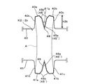
- FIG. 9 is a schematic explanatory view of the shape of the protrusion after the improvement.
- the shapes of the protrusions 45 and 46 are improved to form protrusions 45 ′ and 46 ′.
- It is an explanatory view showing composition of hole type K2-2a.
- FIG. 9 also shows an enlarged view in which the vicinity of the upper protruding portion 45 ′ is enlarged.
- the same reference numerals are used for the components having the same functional configuration as the 2-2nd hole type K2-2 (before the improvement) described above with reference to FIG. It is shown using, and the explanation may be omitted.
- the height of the entire projections 45 ′, 46 ′ after the improvement is h 2 b as is the height of the projections 45, 46.
- the height of the tip portion 45a (46a) is h and the height of the root portion 45b (46b) is h ', these heights h and h' are the contacts described below within the numerical range of h2b
- the width ratio L / B can be designed to be a predetermined value.
- the angle ⁇ 1 b is preferably 25 ° or more and 40 ° or less as in the case of the second and second hole type K 2-2 described with reference to FIG.
- the value of ⁇ 4 can be arbitrarily designed as a value larger than this ⁇ 1 b.
- the value of ⁇ 4 is the wedge angle ⁇ 2 of the bending hole shape of the latter stage because of the forming conditions in which the bending shape forming of the third hole shape K3 is performed after the interruption forming in the 2-2 hole shape K2-2a.
- the following angle is required, and it is preferable to set the same angle as ⁇ 2. The reason why it is preferable that ⁇ 4 and ⁇ 2 be the same angle will be described later in the second embodiment.
- the present inventors relate to the hole shape shape of the 2-2 hole type K2-2a, about the to-be-rolled material A in which the hole type filling was completed by the interruption shaping
- the ratio L / B of the base portion width L (width length of the base portion 45b) to the flange contact width B at the time of filling (the flange piece width before bending and shaping) was defined (see FIG. 9).
- the contact width ratio L / B is preferably 0.20 or more, and more preferably 0.20 or more and 0.24 or less.
- the basis of the numerical range of the contact width ratio L / B will be described with reference to Tables 1 to 4 and the like in Examples described later.
- the projections 45 ′ and 46 ′ It is comprised by the front-end
- a H-shaped steel product having a large flange width and a thick flange is required.
- a large H-shaped steel product having a large flange thickness such as a height of 1200 mm ⁇ a width of 500 mm from a material slab of 300 mm thickness. In such a case, thinning of the flange thickness is not preferable.
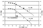
- FIG. 10 is a graph showing the relationship between the flange width and the numerical value of the flange thickness when the wedge angle ⁇ 1b is changed.
- FIG. 10 is a graph showing the result of FEM analysis of the relationship between the flange thickness and the flange width in the subsequent step (bending and forming) when the wedge angle .theta.1b of the interruption hole type is changed.
- the flange width and the flange thickness decrease as the wedge angle ⁇ 1b increases. Therefore, from the viewpoint of securing the flange formation efficiency, it is estimated that the wedge angle ⁇ 4 of the root portion 45b (46b) of the improved projections 45 'and 46' has an upper limit value.
- the height h of the tip portion 45a (46a), the height h 'of the root portion 45b (46b), and the wedge angle ⁇ 4 of the root portion in the technology according to the present embodiment.
- an interrupting hole type (second 2-2 hole type K2-2a) having a configuration according to the improved projections 45 ′ and 46 ′.
- the material to be rolled A is formed using the group of holes shown and described as the first through fourth holes K1 to K4, and then the flat-shape rolling is performed using the fifth hole K5.
- the technology to do the number of hole types for carrying out the rough rolling process is not limited to this. That is, the hole type configuration shown in the above embodiment is an example, and the number of hole types engraved in the sizing mill 3 and the rough rolling mill 4 can be arbitrarily changed, and the rough rolling process is preferably performed. It is suitably changed to the extent that it can do. In particular, the so-called "interruption molding" has been described as being performed in two types of 2-1 hole type K2-1 and 2-2 hole type K2-2 having different interrupt lengths.
- the interruption hole type may be a single-hole type, or may be constituted by three or more types of hole types having different interruption lengths.
- mold is multiple types, the improvement technique of the projection part shape which concerns on this invention is applied to the last interruption hole type
- the present inventors further study the hole shape of the interrupt hole type having the configuration according to the protrusions 45 ′ and 46 ′, and solve the problems related to the shape defect as described above.
- a second 2-2 hole type K2-2b having a newly devised configuration will be described with reference to the drawings.
- FIG. 11 is a schematic explanatory view of a second hole type K2-2b according to a modification of the present invention.
- components having the same functional configurations as those of the second through-hole type K2-2a (see FIG. 9) described in the above embodiment are indicated by the same reference numerals. I omit it.
- the basic hole-type configuration of the 2-2nd-hole type K2-2b according to the present modification is substantially the same as the 2-2nd-hole type K2-2a.
- the difference is that the side surfaces 40c and 41c formed on the left and right of the hole form abut on the material to be rolled A so as to restrain the material to be rolled A. That is, while the second 2-2 hole type K2-2a described in the above embodiment is configured without the side wall, the 2-2nd hole type K2-2b according to the present modification is provided with the side wall. Configuration (hole type design).
- the contact portion of the material to be rolled A with the side surfaces 40c and 41c be the largest in thickness of the material to be rolled A immediately after being introduced into the second 2-2 hole type K2-2b.
- the contact point is generally in the vicinity of the central portion of the outer surface of the flange equivalent portion (flange portion 80) of the material to be rolled A. This means that the outer surface shape of the material to be rolled A becomes a shape close to perpendicular when the wedge angle ⁇ 1a of the first hole type K1 and the wedge angle ⁇ 1b of the second hole type K2-2b are the same angle. Due to.
- holes are generated in the middle pass except for the protrusions 45 ′ and 46 ′ at the upper and lower end portions (slab end faces) of the material to be rolled A
- the mold and the material to be rolled A are not in contact with each other, and no positive reduction of the material to be rolled A is performed in these passes. This is because the reduction in pressure causes elongation of the material to be rolled A in the longitudinal direction, and the generation efficiency of the flange equivalent portion (flange portion 80) is reduced.
- the shaping pass schedule such that the upper and lower end portions of the material to be rolled A make full contact in the final pass or several passes before the final pass.
- the shapes of the hole side surfaces 40c and 41c are vertical shapes perpendicular to the hole roll axis from the viewpoint of efficiently constraining the material to be rolled A from the left and right.
- an interrupting hole type having the configuration according to the improved projections 45 'and 46' described in the above embodiment (2-2 hole type K2-2a, see FIG. 9) It verified about the existence of generation
- Table 1 is a table showing the basic design of the hole type for flange thickening in each hole type when manufacturing a 1000 ⁇ 500 mm H-shaped steel product using a slab of 2000 ⁇ 250 mm cross section or 2000 ⁇ 300 mm cross section as a raw material It is. Specifically, when edging rolling is performed on the upper and lower ends of the slab in each of the second through-hole type K2-1, the second through-hole type K2-2, the third through-hole type K3, and the fourth through-hole type K4. Describes the pore-type design of The projection height (wedge height) in Table 1 is the projection height at one of the upper and lower sides of each of the hole types. In the present example, of the basic design of hole type shown in Table 1, the improvement was carried out by improving the protrusion described in the above embodiment with respect to the 2-2nd hole type K2-2.
- the comparative example is a case where the hole type configuration before improvement (the 2-2nd hole type K2-2, see FIG. 4) is used.
- Tables 2 to 4 below show the relationship between the thickness of the flange of the material to be rolled and the occurrence of wrinkles in the comparative example, the example 1, and the example 2.
- the contact width ratio L / B in the comparative example is 0.00
- the contact width ratio L / B in the first embodiment is 0.20
- the contact width ratio L / B in the second embodiment is 0.24.
- the wedge angle ( ⁇ 4) of the root portion in the interruption hole type (No. 2-2 hole type K2-2a, see FIG. 9) having the configuration according to the improved projections 45 'and 46'
- the contact width ratio L / B is 0.24 with 90 °, the generation of wrinkles is not confirmed even when the flange thickness is formed to any thickness of 160 mm to 210 mm.
- the H-shaped steel product is rolled and shaped by the method of manufacturing an H-shaped steel according to the present invention described in the above embodiment Is basically half the slab thickness (about 150 mm). Then, by actively performing edging rolling on the front end of the slab from a state where the flange thickness is half the thickness of the slab, the thickness of the flange is increased, for example, a process of manufacturing a product having a flange thickness of about 180 mm or more Design is made.
- the inventors of the present invention have created the shape of the projection having the root portion described in the above-described embodiment, and reduced the pressure by increasing the contact area between the roll and the material to be rolled, thereby causing the generation of the rasp. It is suppressing.
- the contact width ratio L / B it is desirable to increase the contact area between the roll and the material to be rolled, in order to suppress the generation of the gutter, and it is desirable to secure a certain value of the contact width ratio L / B.
- the value of the contact width ratio L / B is desirably 0.20 or more.
- the contact width ratio L / B is 0.24, the rolling and shaping can be performed without generating the rasp to the extent that the flange thickness exceeds 200 mm, so the contact width ratio
- the preferable range of L / B may be 0.20 to 0.24.
- FIG. 12 is a graph showing the vertical sliding speed between the roll and the material to be rolled under each condition.
- the said "roll bit" points out the area
- the sliding velocity in the vertical direction between the roll and the material to be rolled in the roll bit here is the roll and the material to be rolled in the region where the material to be rolled and the roll are in contact at the time of steady state of rolling. And the difference in velocity between the two and the velocity of the region where the difference is maximum.
- Example 1 condition 1
- Example 2 condition 2
- the sliding speed in Example 2 is reduced. From this result, it is understood that the application of the present invention technique makes the deformation accompanying bending and shaping of a portion where the amount of deformation locally increases in the material to be rolled gentler, and the suppression of the sliding crease is realized.
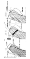
- FIG. 13 is a schematic view showing deformation simulation results by FEM analysis under each condition of the comparative example, the example 1, and the example 2, where (a) is a comparative example, (b) is an example 1, (c) These show Example 2.
- a solid line indicates a state before bending shaping and after bending shaping, and a mesh illustrates a first pass finished shape of bending shaping.
- the shape of the conventional method is also collectively shown in (b) and (c) as a comparison.
- the pass schedule design is common, and the roll shape of the second stage hole type (third hole type K3) is the same.
- the shape of the projection has a shape having a root portion (the first embodiment See 2-2 hole type K2-2a).
- an interrupting hole type having the configuration according to the improved projections 45 'and 46' described in the above embodiment (2-2 hole type K2-2a, see FIG. 9)
- the wedge angle ⁇ 2 of the first bending hole type (third hole type K3, see FIG. 5) and the wedge angle ⁇ 4 of the base portion are equal, and the angle range is 60 ° to 110 It verified about the presence or absence of generation
- Table 5 shows the relationship between the flange thickness of the material to be rolled and the occurrence of wrinkles when the wedge angle ⁇ 1 b of the interruption hole type and the angles ⁇ 2 and ⁇ 4 are set as the respective conditions.
- when shaping was performed with a flange thickness of 210 mm generation of wrinkles was confirmed under some conditions.
- the present invention can be applied to a manufacturing method for manufacturing an H-shaped steel, for example, using a slab having a rectangular cross section as a raw material.
- Upper hole type roll (2nd 2 hole type) 41 Lower hole type roll (No. 2-2 hole type) 45, 46 ... Protrusions (2nd-2 hole type) 45a, 46a ... tip 45b, 46b ... root 48, 49 ... interruption (2nd-2 hole type) 50 ... Upper hole type roll (3rd hole type) 51 ⁇ Lower hole type roll (3rd hole type) 55, 56 ... Protrusions (third hole type) 58, 59 ... Interruption (3rd hole type) 60 ... Upper hole type roll (4th hole type) 61 ⁇ Lower hole type roll (4th hole type) 65, 66 ... projection (fourth hole type) 68, 69 ... Interruption (4th hole type) 80 ... flange portion 82 ...
Landscapes
- Engineering & Computer Science (AREA)
- Mechanical Engineering (AREA)
- Metal Rolling (AREA)
- Reduction Rolling/Reduction Stand/Operation Of Reduction Machine (AREA)
- Rod-Shaped Construction Members (AREA)
Abstract
Le procédé de fabrication d'une poutrelle d'acier à profil en H selon l'invention comporte une étape de laminage de dégrossissage, une étape de laminage intermédiaire et une étape de laminage de finition. Une machine de laminage qui réalise l'étape de laminage de dégrossissage est pourvue d'une pluralité de rainures qui façonnent un matériau à laminer. La pluralité de rainures comprend : une ou une pluralité de rainures de division, dans lesquelles sont formées des saillies qui entraînent la formation d'une partie divisée dans une partie d'extrémité du matériau à laminer, par formation d'une entaille dans une direction perpendiculaire au sens de la largeur du matériau à laminer ; et une pluralité de rainures de pliage, dans lesquelles sont formées des saillies qui entrent en contact avec l'entaille et plient séquentiellement la partie divisée formée au niveau de la rainure de division. La saillie formée dans une rainure de division finale parmi les rainures de division est constituée par une partie de pointe effilée, qui présente un angle de pointe prescrit, et une partie de base située au niveau de la base de la partie de pointe, et qui présente une forme effilée avec une pente plus douce que la partie de pointe
Priority Applications (5)
| Application Number | Priority Date | Filing Date | Title |
|---|---|---|---|
| JP2018554591A JP6501047B1 (ja) | 2017-07-12 | 2018-07-11 | H形鋼の製造方法 |
| US16/628,911 US20200206802A1 (en) | 2017-07-12 | 2018-07-11 | Method for producing h-shaped steel |
| EP18832051.9A EP3650131A1 (fr) | 2017-07-12 | 2018-07-11 | Procédé de fabrication d'une poutrelle d'acier à profil en h |
| CN201880046044.4A CN110891701A (zh) | 2017-07-12 | 2018-07-11 | H型钢的制造方法 |
| PH12020500038A PH12020500038A1 (en) | 2017-07-12 | 2020-01-03 | Method for producing h-shaped steel |
Applications Claiming Priority (2)
| Application Number | Priority Date | Filing Date | Title |
|---|---|---|---|
| JP2017136551 | 2017-07-12 | ||
| JP2017-136551 | 2017-07-12 |
Publications (1)
| Publication Number | Publication Date |
|---|---|
| WO2019013262A1 true WO2019013262A1 (fr) | 2019-01-17 |
Family
ID=65001710
Family Applications (1)
| Application Number | Title | Priority Date | Filing Date |
|---|---|---|---|
| PCT/JP2018/026218 Ceased WO2019013262A1 (fr) | 2017-07-12 | 2018-07-11 | Procédé de fabrication d'une poutrelle d'acier à profil en h |
Country Status (6)
| Country | Link |
|---|---|
| US (1) | US20200206802A1 (fr) |
| EP (1) | EP3650131A1 (fr) |
| JP (1) | JP6501047B1 (fr) |
| CN (1) | CN110891701A (fr) |
| PH (1) | PH12020500038A1 (fr) |
| WO (1) | WO2019013262A1 (fr) |
Citations (3)
| Publication number | Priority date | Publication date | Assignee | Title |
|---|---|---|---|---|
| JPH0788501A (ja) | 1993-09-21 | 1995-04-04 | Nippon Steel Corp | H形鋼用中間粗形鋼片の製造方法 |
| JPH11347601A (ja) | 1998-06-03 | 1999-12-21 | Nkk Corp | 粗形鋼片の圧延方法 |
| JP2016144811A (ja) * | 2015-02-06 | 2016-08-12 | 新日鐵住金株式会社 | フランジを有する形鋼のエッジャー圧延機 |
Family Cites Families (6)
| Publication number | Priority date | Publication date | Assignee | Title |
|---|---|---|---|---|
| JPS5953121B2 (ja) * | 1981-03-05 | 1984-12-24 | 川崎製鉄株式会社 | 粗形鋼片用大型素材の幅出し圧延方法とその圧延用ロ−ル |
| LU85950A1 (fr) * | 1985-06-13 | 1987-01-13 | Arbed | Procede et dispositif pour laminer des ebauches de poutrelles hors brames de coulee continue |
| JPS62230401A (ja) * | 1986-03-31 | 1987-10-09 | Sumitomo Metal Ind Ltd | H形鋼の粗圧延方法 |
| JP3521122B2 (ja) * | 1999-04-26 | 2004-04-19 | 愛知製鋼株式会社 | H形鋼の製造方法 |
| WO2016148030A1 (fr) * | 2015-03-19 | 2016-09-22 | 新日鐵住金株式会社 | Procédé de fabrication d'un acier en forme de h |
| CN105057345B (zh) * | 2015-08-21 | 2017-03-22 | 天津市中重科技工程有限公司 | 一种万能轧机劈轧板坯生产h型钢的方法 |
-
2018
- 2018-07-11 WO PCT/JP2018/026218 patent/WO2019013262A1/fr not_active Ceased
- 2018-07-11 EP EP18832051.9A patent/EP3650131A1/fr not_active Withdrawn
- 2018-07-11 US US16/628,911 patent/US20200206802A1/en not_active Abandoned
- 2018-07-11 CN CN201880046044.4A patent/CN110891701A/zh active Pending
- 2018-07-11 JP JP2018554591A patent/JP6501047B1/ja active Active
-
2020
- 2020-01-03 PH PH12020500038A patent/PH12020500038A1/en unknown
Patent Citations (3)
| Publication number | Priority date | Publication date | Assignee | Title |
|---|---|---|---|---|
| JPH0788501A (ja) | 1993-09-21 | 1995-04-04 | Nippon Steel Corp | H形鋼用中間粗形鋼片の製造方法 |
| JPH11347601A (ja) | 1998-06-03 | 1999-12-21 | Nkk Corp | 粗形鋼片の圧延方法 |
| JP2016144811A (ja) * | 2015-02-06 | 2016-08-12 | 新日鐵住金株式会社 | フランジを有する形鋼のエッジャー圧延機 |
Also Published As
| Publication number | Publication date |
|---|---|
| PH12020500038A1 (en) | 2020-09-14 |
| JPWO2019013262A1 (ja) | 2019-07-11 |
| US20200206802A1 (en) | 2020-07-02 |
| CN110891701A (zh) | 2020-03-17 |
| EP3650131A1 (fr) | 2020-05-13 |
| JP6501047B1 (ja) | 2019-04-17 |
Similar Documents
| Publication | Publication Date | Title |
|---|---|---|
| JP2019111584A (ja) | 圧延h形鋼 | |
| KR20190030755A (ko) | H형강의 제조 방법 | |
| JP6447286B2 (ja) | H形鋼の製造方法及びh形鋼製品 | |
| JP6501047B1 (ja) | H形鋼の製造方法 | |
| JP6536415B2 (ja) | H形鋼の製造方法 | |
| JP6668963B2 (ja) | H形鋼の製造方法 | |
| CN111479638A (zh) | H型钢的制造方法 | |
| JP6724672B2 (ja) | H形鋼の製造方法 | |
| JP6614339B2 (ja) | H形鋼の製造方法 | |
| JP6515365B1 (ja) | H形鋼の製造方法 | |
| JP6686809B2 (ja) | H形鋼の製造方法 | |
| JP6593457B2 (ja) | H形鋼の製造方法及び圧延装置 | |
| JP6627641B2 (ja) | H形鋼の製造方法 | |
| CN107427873B (zh) | H型钢的制造方法 | |
| JP6790973B2 (ja) | H形鋼の製造方法 | |
| JP6593456B2 (ja) | H形鋼の製造方法及びh形鋼製品 | |
| JP6855885B2 (ja) | H形鋼の製造方法及びh形鋼製品 | |
| JPWO2018216742A1 (ja) | H形鋼の製造方法 | |
| JP6569535B2 (ja) | H形鋼の製造方法及びh形鋼製品 | |
| JP5938983B2 (ja) | 粗形鋼片の造形圧延方法およびh形鋼の製造方法 | |
| JP2019206010A (ja) | H形鋼の製造方法 | |
| JP2017121652A (ja) | H形鋼の製造方法 |
Legal Events
| Date | Code | Title | Description |
|---|---|---|---|
| ENP | Entry into the national phase |
Ref document number: 2018554591 Country of ref document: JP Kind code of ref document: A |
|
| 121 | Ep: the epo has been informed by wipo that ep was designated in this application |
Ref document number: 18832051 Country of ref document: EP Kind code of ref document: A1 |
|
| NENP | Non-entry into the national phase |
Ref country code: DE |
|
| ENP | Entry into the national phase |
Ref document number: 2018832051 Country of ref document: EP Effective date: 20200204 |